Back pan cooling assembly for electronic display
Dunn , et al.
U.S. patent number 10,660,245 [Application Number 14/055,499] was granted by the patent office on 2020-05-19 for back pan cooling assembly for electronic display. This patent grant is currently assigned to MANUFACTURING RESOURCES INTERNATIONAL, INC.. The grantee listed for this patent is Manufacturing Resources International, Inc.. Invention is credited to Mike Brown, William Dunn, Tim Hubbard.

| United States Patent | 10,660,245 |
| Dunn , et al. | May 19, 2020 |
Back pan cooling assembly for electronic display
Abstract
Exemplary embodiments disclosed herein provide a back pan cooling assembly for an electronic display having a rear pan. A cooling back pan is preferably positioned behind the rear pan, the space between the cooling back pan and the rear pan defining a gap. A fan is positioned to cause a flow of ambient air through the gap. An electronic component for driving the electronic display may be placed in conductive thermal communication with the cooling back pan. A rear cover can be placed against the cooling back pan to define a sealed compartment which does not permit ambient air to enter. A port can be provided within the rear cover which allows ambient air to travel between the surroundings, the fan, and the gap.
| Inventors: | Dunn; William (Alpharetta, GA), Brown; Mike (Alpharetta, GA), Hubbard; Tim (Alpharetta, GA) | ||||||||||
|---|---|---|---|---|---|---|---|---|---|---|---|
| Applicant: |
|
||||||||||
| Assignee: | MANUFACTURING RESOURCES
INTERNATIONAL, INC. (Alpharetta, GA) |
||||||||||
| Family ID: | 50485758 | ||||||||||
| Appl. No.: | 14/055,499 | ||||||||||
| Filed: | October 16, 2013 |
Prior Publication Data
| Document Identifier | Publication Date | |
|---|---|---|
| US 20140113540 A1 | Apr 24, 2014 | |
Related U.S. Patent Documents
| Application Number | Filing Date | Patent Number | Issue Date | ||
|---|---|---|---|---|---|
| 61714381 | Oct 16, 2012 | ||||
| Current U.S. Class: | 1/1 |
| Current CPC Class: | H05K 7/20972 (20130101) |
| Current International Class: | H05K 7/20 (20060101) |
| Field of Search: | ;454/184 |
References Cited [Referenced By]
U.S. Patent Documents
| 4093355 | June 1978 | Kaplit et al. |
| 4593978 | June 1986 | Mourey et al. |
| 4634225 | January 1987 | Haim et al. |
| 4748765 | June 1988 | Martin |
| 4763993 | August 1988 | Vogeley et al. |
| 4921041 | May 1990 | Akachi |
| 4952783 | August 1990 | Aufderheide et al. |
| 4952925 | August 1990 | Haastert |
| 5029982 | July 1991 | Nash |
| 5088806 | February 1992 | McCartney et al. |
| 5247374 | September 1993 | Terada |
| 5282114 | January 1994 | Stone |
| 5293930 | March 1994 | Pitasi |
| 5432526 | July 1995 | Hyatt |
| 5535816 | July 1996 | Ishida |
| 5559614 | September 1996 | Urbish et al. |
| 5621614 | April 1997 | O'Neill |
| 5657641 | August 1997 | Cunningham et al. |
| 5748269 | May 1998 | Harris et al. |
| 5765743 | June 1998 | Sakiura et al. |
| 5767489 | June 1998 | Ferrier |
| 5808418 | September 1998 | Pitman et al. |
| 5818010 | October 1998 | McCann |
| 5818694 | October 1998 | Daikoku et al. |
| 5835179 | November 1998 | Yamanaka |
| 5864465 | January 1999 | Liu |
| 5869818 | February 1999 | Kim |
| 5869919 | February 1999 | Sato et al. |
| 5903433 | May 1999 | Gudmundsson |
| 5991153 | November 1999 | Heady et al. |
| 6003015 | December 1999 | Kang et al. |
| 6007205 | December 1999 | Fujimori |
| 6089751 | July 2000 | Conover et al. |
| 6104451 | August 2000 | Matsuoka et al. |
| 6157432 | December 2000 | Helbing |
| 6181070 | January 2001 | Dunn et al. |
| 6191839 | February 2001 | Briley et al. |
| 6198222 | March 2001 | Chang |
| 6211934 | April 2001 | Habing et al. |
| 6215655 | April 2001 | Heady et al. |
| 6351381 | February 2002 | Bilski et al. |
| 6392727 | May 2002 | Larson et al. |
| 6417900 | July 2002 | Shin et al. |
| 6428198 | August 2002 | Saccomanno et al. |
| 6437673 | August 2002 | Nishida |
| 6473150 | October 2002 | Takushima et al. |
| 6476883 | November 2002 | Salimes |
| 6493440 | December 2002 | Gromatsky et al. |
| 6504713 | January 2003 | Pandolfi et al. |
| 6535266 | March 2003 | Nemeth et al. |
| 6628355 | September 2003 | Takahara |
| 6683639 | January 2004 | Scheper |
| 6714410 | March 2004 | Wellhofer |
| 6727468 | April 2004 | Nemeth |
| 6825828 | November 2004 | Burke et al. |
| 6839104 | January 2005 | Taniguchi et al. |
| 6885412 | April 2005 | Ohnishi et al. |
| 6886942 | May 2005 | Okada et al. |
| 6891135 | May 2005 | Pala et al. |
| 6909486 | June 2005 | Wang et al. |
| 6943768 | September 2005 | Cavanaugh et al. |
| 6961108 | November 2005 | Wang et al. |
| 7015470 | March 2006 | Faytlin et al. |
| 7059757 | June 2006 | Shimizu |
| 7083285 | August 2006 | Hsu et al. |
| 7157838 | January 2007 | Thielemans et al. |
| 7161803 | January 2007 | Heady |
| 7190587 | March 2007 | Kim et al. |
| 7209349 | April 2007 | Chien et al. |
| 7212403 | May 2007 | Rockenfeller |
| 7269023 | September 2007 | Nagano |
| 7284874 | October 2007 | Jeong et al. |
| 7396145 | July 2008 | Wang |
| 7452121 | November 2008 | Cho et al. |
| 7457113 | November 2008 | Kumhyr |
| 7480140 | January 2009 | Hara et al. |
| 7535543 | May 2009 | Dewa et al. |
| 7602469 | October 2009 | Shin |
| D608775 | January 2010 | Leung |
| 7667964 | February 2010 | Kang et al. |
| 7752858 | July 2010 | Johnson et al. |
| 7753567 | July 2010 | Kang et al. |
| 7762707 | July 2010 | Kim |
| 7800706 | September 2010 | Kim |
| 7813124 | October 2010 | Karppanen |
| 7903416 | March 2011 | Chou |
| 7995342 | August 2011 | Nakamichi et al. |
| 8004648 | August 2011 | Dunn |
| 8035968 | October 2011 | Kwon et al. |
| 8081465 | December 2011 | Nishiura |
| 8102173 | January 2012 | Merrow |
| 8142027 | March 2012 | Sakai |
| 8208115 | June 2012 | Dunn |
| 8223311 | July 2012 | Kim et al. |
| 8241573 | August 2012 | Banerjee et al. |
| 8248784 | August 2012 | Nakamichi et al. |
| 8254121 | August 2012 | Lee |
| 8269916 | September 2012 | Ohkawa |
| 8270163 | September 2012 | Nakamichi et al. |
| 8274622 | September 2012 | Dunn |
| 8274789 | September 2012 | Nakamichi et al. |
| 8300203 | October 2012 | Nakamichi et al. |
| 8320119 | November 2012 | Isoshima et al. |
| 8351014 | January 2013 | Dunn |
| 8358397 | January 2013 | Dunn |
| 8369083 | February 2013 | Dunn |
| 8373841 | February 2013 | Dunn |
| 8379182 | February 2013 | Dunn |
| 8400608 | March 2013 | Takahashi |
| 8472174 | June 2013 | Idems et al. |
| 8472191 | June 2013 | Yamamoto et al. |
| 8482695 | July 2013 | Dunn |
| 8497972 | July 2013 | Dunn et al. |
| 8649170 | February 2014 | Dunn et al. |
| 8649176 | February 2014 | Okada et al. |
| 8654302 | February 2014 | Dunn |
| 8678603 | March 2014 | Zhang |
| 8693185 | April 2014 | Dunn |
| 8700226 | April 2014 | Schuch et al. |
| 8711321 | April 2014 | Dunn |
| 8749749 | June 2014 | Hubbard |
| 8755021 | June 2014 | Hubbard |
| 8760613 | June 2014 | Dunn |
| 8767165 | July 2014 | Dunn |
| 8773633 | July 2014 | Dunn et al. |
| 8804091 | August 2014 | Dunn |
| 8823916 | September 2014 | Hubbard |
| 8854572 | October 2014 | Dunn |
| 8854595 | October 2014 | Dunn |
| 8879042 | November 2014 | Dunn |
| 8988647 | March 2015 | Hubbard |
| 9030641 | May 2015 | Dunn |
| 9089079 | July 2015 | Dunn |
| 9119325 | August 2015 | Dunn et al. |
| 9119330 | August 2015 | Hubbard et al. |
| 9173322 | October 2015 | Dunn |
| 9173325 | October 2015 | Dunn |
| 9282676 | March 2016 | Diaz |
| 9285108 | March 2016 | Dunn et al. |
| 9313917 | April 2016 | Dunn et al. |
| 9370127 | June 2016 | Dunn |
| 9448569 | September 2016 | Schuch et al. |
| 9451060 | September 2016 | Bowers et al. |
| 9451733 | September 2016 | Dunn et al. |
| 9456525 | September 2016 | Yoon |
| 9470924 | October 2016 | Dunn et al. |
| 9500896 | November 2016 | Dunn |
| 9516485 | December 2016 | Bowers et al. |
| 9549490 | January 2017 | Hubbard |
| 9594271 | March 2017 | Dunn et al. |
| 9613548 | April 2017 | DeMars |
| 9622392 | April 2017 | Bowers et al. |
| 9629287 | April 2017 | Dunn |
| 9648790 | May 2017 | Dunn et al. |
| 9655289 | May 2017 | Dunn |
| 9723765 | August 2017 | DeMars |
| 9797588 | October 2017 | Dunn |
| 9894800 | February 2018 | Dunn |
| 2001/0001459 | May 2001 | Savant et al. |
| 2001/0019454 | September 2001 | Tadic-Galeb |
| 2002/0033919 | March 2002 | Sanelle et al. |
| 2002/0050793 | May 2002 | Cull et al. |
| 2002/0101553 | August 2002 | Enomoto et al. |
| 2002/0126248 | September 2002 | Yoshia |
| 2002/0148600 | October 2002 | Bosch et al. |
| 2002/0149714 | October 2002 | Anderson et al. |
| 2002/0154255 | October 2002 | Gromatzky |
| 2002/0164944 | November 2002 | Haglid |
| 2002/0167637 | November 2002 | Burke et al. |
| 2003/0007109 | January 2003 | Park |
| 2003/0020884 | January 2003 | Okada et al. |
| 2003/0104210 | June 2003 | Azumi et al. |
| 2003/0128511 | July 2003 | Nagashima et al. |
| 2003/0214785 | November 2003 | Perazzo |
| 2004/0012722 | January 2004 | Alvarez |
| 2004/0035558 | February 2004 | Todd et al. |
| 2004/0036834 | February 2004 | Ohnishi et al. |
| 2004/0103570 | June 2004 | Ruttenberg |
| 2004/0105159 | June 2004 | Saccomanno et al. |
| 2004/0165139 | August 2004 | Anderson et al. |
| 2004/0223299 | November 2004 | Ghosh |
| 2005/0012039 | January 2005 | Faytlin et al. |
| 2005/0012722 | January 2005 | Chon |
| 2005/0062373 | March 2005 | Kim et al. |
| 2005/0073632 | April 2005 | Dunn et al. |
| 2005/0073639 | April 2005 | Pan |
| 2005/0134525 | June 2005 | Tanghe et al. |
| 2005/0134526 | June 2005 | Willem et al. |
| 2005/0213950 | September 2005 | Yoshimura |
| 2005/0229630 | October 2005 | Richter et al. |
| 2005/0237714 | October 2005 | Ebermann |
| 2005/0276053 | December 2005 | Nortrup et al. |
| 2005/0286131 | December 2005 | Saxena et al. |
| 2006/0012958 | January 2006 | Tomioka et al. |
| 2006/0018093 | January 2006 | Lai et al. |
| 2006/0034051 | February 2006 | Wang et al. |
| 2006/0056994 | March 2006 | Van Lear et al. |
| 2006/0082271 | April 2006 | Lee et al. |
| 2006/0092348 | May 2006 | Park |
| 2006/0125998 | June 2006 | Dewa et al. |
| 2006/0132699 | June 2006 | Cho et al. |
| 2006/0177587 | August 2006 | Ishizuka et al. |
| 2006/0199514 | September 2006 | Kimura |
| 2006/0209266 | September 2006 | Utsunomiya |
| 2006/0260790 | November 2006 | Theno et al. |
| 2006/0262079 | November 2006 | Seong et al. |
| 2006/0266499 | November 2006 | Choi et al. |
| 2006/0283579 | December 2006 | Ghosh |
| 2007/0019419 | January 2007 | Hafuka et al. |
| 2007/0030879 | February 2007 | Hatta |
| 2007/0047239 | March 2007 | Kang et al. |
| 2007/0065091 | March 2007 | Hinata et al. |
| 2007/0076431 | April 2007 | Atarashi et al. |
| 2007/0103863 | May 2007 | Kim |
| 2007/0103866 | May 2007 | Park |
| 2007/0115686 | May 2007 | Tyberghien |
| 2007/0139929 | June 2007 | Yoo et al. |
| 2007/0140671 | June 2007 | Yoshimura |
| 2007/0151274 | July 2007 | Roche et al. |
| 2007/0151664 | July 2007 | Shin |
| 2007/0171353 | July 2007 | Hong |
| 2007/0206158 | September 2007 | Kinoshita et al. |
| 2007/0211205 | September 2007 | Shibata |
| 2007/0212211 | September 2007 | Chiyoda et al. |
| 2007/0217221 | September 2007 | Lee et al. |
| 2007/0237636 | October 2007 | Hsu |
| 2007/0267174 | November 2007 | Kim |
| 2008/0055534 | March 2008 | Kawano |
| 2008/0076342 | March 2008 | Bryant et al. |
| 2008/0099193 | May 2008 | Aksamit et al. |
| 2008/0148609 | June 2008 | Ogoreve |
| 2008/0209934 | September 2008 | Richards |
| 2008/0218446 | September 2008 | Yamanaka |
| 2008/0236005 | October 2008 | Isayev et al. |
| 2008/0267790 | October 2008 | Gaudet et al. |
| 2008/0283234 | November 2008 | Sagi et al. |
| 2008/0285290 | November 2008 | Ohashi et al. |
| 2009/0009047 | January 2009 | Yanagawa et al. |
| 2009/0009729 | January 2009 | Sakai |
| 2009/0086430 | April 2009 | Kang |
| 2009/0120629 | May 2009 | Ashe |
| 2009/0122218 | May 2009 | Oh et al. |
| 2009/0126906 | May 2009 | Dunn |
| 2009/0126907 | May 2009 | Dunn |
| 2009/0126914 | May 2009 | Dunn |
| 2009/0135365 | May 2009 | Dunn |
| 2009/0147170 | June 2009 | Oh et al. |
| 2009/0154096 | June 2009 | Iyengar et al. |
| 2009/0174626 | July 2009 | Isoshima et al. |
| 2009/0244472 | October 2009 | Dunn |
| 2009/0279240 | November 2009 | Karppanen |
| 2009/0306820 | December 2009 | Simmons et al. |
| 2010/0060861 | March 2010 | Medin |
| 2010/0079949 | April 2010 | Nakamichi |
| 2010/0162747 | July 2010 | Hamel et al. |
| 2010/0171889 | July 2010 | Pantel et al. |
| 2010/0182562 | July 2010 | Yoshida et al. |
| 2010/0220249 | September 2010 | Nakamichi et al. |
| 2010/0226091 | September 2010 | Dunn |
| 2010/0232107 | September 2010 | Dunn |
| 2010/0238394 | September 2010 | Dunn |
| 2010/0321887 | December 2010 | Kwon et al. |
| 2011/0001898 | January 2011 | Mikubo et al. |
| 2011/0013114 | January 2011 | Dunn et al. |
| 2011/0019363 | January 2011 | Vahlsing et al. |
| 2011/0051071 | March 2011 | Nakamichi |
| 2011/0058326 | March 2011 | Idems et al. |
| 2011/0075361 | March 2011 | Nakamichi et al. |
| 2011/0083460 | April 2011 | Thomas et al. |
| 2011/0083824 | April 2011 | Rogers |
| 2011/0085301 | April 2011 | Dunn |
| 2011/0114384 | May 2011 | Sakamoto et al. |
| 2011/0116000 | May 2011 | Dunn et al. |
| 2011/0122162 | May 2011 | Sato et al. |
| 2011/0141724 | June 2011 | Erion |
| 2011/0261523 | October 2011 | Dunn et al. |
| 2012/0006523 | January 2012 | Masahiro et al. |
| 2012/0012295 | January 2012 | Kakiuchi et al. |
| 2012/0012300 | January 2012 | Dunn et al. |
| 2012/0014063 | January 2012 | Weiss |
| 2012/0020114 | January 2012 | Miyamoto et al. |
| 2012/0038849 | February 2012 | Dunn et al. |
| 2012/0044217 | February 2012 | Okada et al. |
| 2012/0106081 | May 2012 | Hubbard et al. |
| 2012/0188481 | July 2012 | Kang et al. |
| 2012/0206687 | August 2012 | Dunn et al. |
| 2012/0249402 | October 2012 | Kang |
| 2012/0255704 | October 2012 | Nakamichi |
| 2012/0274876 | November 2012 | Cappaert |
| 2012/0284547 | November 2012 | Culbert et al. |
| 2013/0170140 | July 2013 | Dunn |
| 2013/0176517 | July 2013 | Kim et al. |
| 2013/0201685 | August 2013 | Messmore et al. |
| 2013/0258659 | October 2013 | Erion |
| 2013/0294039 | November 2013 | Chao |
| 2014/0085564 | March 2014 | Hendren |
| 2014/0111758 | April 2014 | Dunn et al. |
| 2014/0113540 | April 2014 | Dunn et al. |
| 2014/0184980 | July 2014 | Onoue |
| 2014/0313698 | October 2014 | Dunn et al. |
| 2014/0314395 | October 2014 | Dunn et al. |
| 2015/0264826 | September 2015 | Dunn et al. |
| 2015/0319882 | November 2015 | Dunn et al. |
| 2015/0366101 | December 2015 | Dunn et al. |
| 2016/0041423 | February 2016 | Dunn |
| 2016/0044829 | February 2016 | Dunn |
| 2016/0192536 | June 2016 | Diaz |
| 2016/0195254 | July 2016 | Dunn et al. |
| 2016/0198588 | July 2016 | DeMars |
| 2016/0238876 | August 2016 | Dunn et al. |
| 2016/0242329 | August 2016 | DeMars |
| 2016/0242330 | August 2016 | Dunn |
| 2016/0249493 | August 2016 | Dunn et al. |
| 2016/0302331 | October 2016 | Dunn |
| 2017/0023823 | January 2017 | Dunn et al. |
| 2017/0068042 | March 2017 | Dunn et al. |
| 2017/0074453 | March 2017 | Bowers et al. |
| 2017/0083043 | March 2017 | Bowers et al. |
| 2017/0083062 | March 2017 | Bowers et al. |
| 2017/0111486 | April 2017 | Bowers et al. |
| 2017/0111520 | April 2017 | Bowers et al. |
| 2017/0111521 | April 2017 | Bowers et al. |
| 2017/0127579 | May 2017 | Hubbard |
| 2017/0188490 | June 2017 | Dunn et al. |
| 2017/0245400 | August 2017 | Dunn et al. |
| 2017/0257978 | September 2017 | Diaz |
| 2011248190 | May 2011 | AU | |||
| 2702363 | May 2005 | CN | |||
| 1408476 | Apr 2004 | EP | |||
| 1647766 | Apr 2006 | EP | |||
| 1647766 | Apr 2006 | EP | |||
| 1762892 | Mar 2007 | EP | |||
| 1951020 | Jul 2008 | EP | |||
| 2225603 | Sep 2010 | EP | |||
| 2370987 | Oct 2011 | EP | |||
| 2603831 | Jun 2013 | EP | |||
| 2801888 | Nov 2014 | EP | |||
| 2909829 | Aug 2015 | EP | |||
| 3020260 | May 2016 | EP | |||
| 3117693 | Jan 2017 | EP | |||
| 2402205 | Dec 2004 | GB | |||
| 2402205 | Dec 2004 | GB | |||
| 402062015 | Mar 1990 | JP | |||
| 402307080 | Dec 1990 | JP | |||
| 03153212 | Jul 1991 | JP | |||
| 3153212 | Jul 1991 | JP | |||
| 6082745 | Mar 1994 | JP | |||
| 8115788 | May 1996 | JP | |||
| 08194437 | Jul 1996 | JP | |||
| 8194437 | Jul 1996 | JP | |||
| 8339034 | Dec 1996 | JP | |||
| H09246766 | Sep 1997 | JP | |||
| 11160727 | Jun 1999 | JP | |||
| 11160727 | Jun 1999 | JP | |||
| 11296094 | Oct 1999 | JP | |||
| H11296094 | Oct 1999 | JP | |||
| 2001209126 | Aug 2001 | JP | |||
| 2002158475 | May 2002 | JP | |||
| 2002158475 | May 2002 | JP | |||
| 2004053749 | Feb 2004 | JP | |||
| 2005017556 | Jan 2005 | JP | |||
| 2000131682 | May 2005 | JP | |||
| 2005134849 | May 2005 | JP | |||
| 2005134849 | May 2005 | JP | |||
| 2005265922 | Sep 2005 | JP | |||
| 2006513577 | Apr 2006 | JP | |||
| 2007322718 | May 2006 | JP | |||
| 2006148047 | Jun 2006 | JP | |||
| 2006163217 | Jun 2006 | JP | |||
| 2007003638 | Jan 2007 | JP | |||
| 09307257 | Nov 2007 | JP | |||
| 09307257 | Nov 2007 | JP | |||
| 2008010361 | Jan 2008 | JP | |||
| 2008292743 | Dec 2008 | JP | |||
| 2008292743 | Dec 2008 | JP | |||
| 2010024624 | Feb 2010 | JP | |||
| 2010024624 | Feb 2010 | JP | |||
| 200366674 | Nov 2004 | KR | |||
| 20050033986 | Apr 2005 | KR | |||
| 20050033986 | Apr 2005 | KR | |||
| 200401354 | Nov 2005 | KR | |||
| 20060016469 | Feb 2006 | KR | |||
| 20060016469 | Feb 2006 | KR | |||
| 100666961 | Jan 2007 | KR | |||
| 100666961 | Jan 2007 | KR | |||
| 1020070070675 | Apr 2007 | KR | |||
| 1020070070675 | Jul 2007 | KR | |||
| 1020070048294 | Aug 2007 | KR | |||
| 101764381 | Jul 2017 | KR | |||
| 2513043 | Apr 2014 | RU | |||
| WO2005079129 | Aug 2005 | WO | |||
| WO2005079129 | Aug 2005 | WO | |||
| WO2008050660 | May 2008 | WO | |||
| WO2009065125 | May 2009 | WO | |||
| WO2009065125 | May 2009 | WO | |||
| WO2009135308 | Nov 2009 | WO | |||
| WO2010007821 | Feb 2010 | WO | |||
| WO2010080624 | Jul 2010 | WO | |||
| WO2011069084 | Jun 2011 | WO | |||
| WO2011072217 | Jun 2011 | WO | |||
| WO2011140179 | Nov 2011 | WO | |||
| WO2011150078 | Dec 2011 | WO | |||
| WO2012021573 | Feb 2012 | WO | |||
| WO2012024426 | Feb 2012 | WO | |||
| 2013182733 | Dec 2013 | WO | |||
| WO2014149773 | Sep 2014 | WO | |||
| WO2014150036 | Sep 2014 | WO | |||
| WO2015168375 | Nov 2015 | WO | |||
| WO2016102982 | Jun 2016 | WO | |||
| WO2016133852 | Aug 2016 | WO | |||
| WO2017152166 | Sep 2017 | WO | |||
Other References
|
Zeef, Hubing, EMC analysis of 18' LCD Monitor, Aug. 2000, 1 page. cited by applicant . Wankhede, Evaluation of Cooling Solutions for Outdoor Electronics, Sep. 17-19, 2007, 6 pages. cited by applicant . Bureau of Ships Navy Department, Guide Manual of Cooling methods for Electronic Equipment, Mar. 31, 1955, 212 pages. cited by applicant . Scott, Cooling of Electronic Equipment, Apr. 4, 1947, 119 pages. cited by applicant . Sergent, Thermal Management Handbook for Electronic Assemblies, Aug. 14, 1998, 190 pages. cited by applicant . Steinberg, Cooling Techniques for Electronic Equipment First Edition, 1980, 255 pages. cited by applicant . Steinberg, Cooling Techniques for Electronic Equipment Second Edition, 1991, 299 pages. cited by applicant . Yeh, Thermal Management of Microelectronic Equipment, Oct. 15, 2002, 148 pages. cited by applicant . Itsenclosures, Product Catalog, 2009, 48 pages. cited by applicant . Itsenclosures, Standard Product Data Sheet, 2011, 18 pages. cited by applicant . Sunbritetv, All Weather Outdoor LCD Television Model 4610HD, 2008, 1 page. cited by applicant . Sunbritetv, Introduces Two New All-Weather Outdoor Televisions InfoComm 2008, 7 pages. cited by applicant . Itsenclosures, Viewstation, 2017, 16 pages. cited by applicant . Novitsky, Driving LEDs versus CCFLs for LCD backlighting, Nov. 12, 2007, 6 pages. cited by applicant . Federman, Cooling Flat Panel Displays, 2011, 4 pages. cited by applicant . Zeeff, T.M., EMC analysis of an 18'' LCD monitor, 2000, 1 page. cited by applicant. |
Primary Examiner: Moubry; Grant
Assistant Examiner: Faulkner; Ryan L
Attorney, Agent or Firm: Standley Law Group LLP Standley; Jeffrey S. Smith; Adam J.
Parent Case Text
CROSS-REFERENCE TO RELATED APPLICATIONS
This application claims priority to U.S. application Ser. No. 61/714,381 filed on Oct. 16, 2012 and is herein incorporated by reference in its entirety.
Claims
We claim:
1. A back pan cooling assembly for an electronic display having a rear pan, the assembly comprising: a cooling back pan having a front surface and a rear surface, wherein said cooling back pan is positioned behind the rear pan; a gap located between the cooling back pan and the rear pan; a rear cover positioned on the cooling back pan to define a rear compartment formed between the cooling back pan and the rear cover which is substantially sealed to prevent ambient air from entering the rear compartment; a port in the rear cover which accepts ambient air; a fan positioned and configured to, when operated, cause a flow of ambient air to be ingested through the port and be exhausted through the gap; and a power supply or microprocessor for driving the electronic display, the power supply or microprocessor placed at the rear surface of the cooling back pan within the sealed rear compartment and in conductive thermal communication with the cooling back pan; wherein the fan is substantially sealed within the rear compartment such that ambient aft is not permitted to contact the power supply or microprocessor.
2. The cooling assembly of claim 1 wherein: the electronic display is in conductive thermal communication with the rear pan.
3. The cooling assembly of claim 1 further comprising: an LED backlight within the electronic display and placed in thermal communication with the rear pan.
4. The cooling assembly of claim 3 wherein: the LED backlight is a direct-lit LED backlight having a front surface and a rear surface; and the rear pan comprises the rear surface of the direct-lit LED backlight.
5. The cooling assembly of claim 1 wherein: the rear pan and cooling back pan each contain four perimeter edges which are substantially aligned with one another.
6. The cooling assembly of claim 5 wherein: the gap extends to all four perimeter edges of the rear pan and cooling back pan.
7. The cooling assembly of claim 5 wherein: ambient air is permitted to exit the gap along the four perimeter edges of the rear pan and the cooling back pan.
8. A back pan cooling assembly for an electronic display having a rear pan, the assembly comprising: a cooling back pan having a front surface and a rear surface, wherein said cooling back pan is positioned behind the rear pan; a gap located between the cooling back pan and the rear pan; a rear cover positioned on the cooling back pan to define a rear compartment formed between the cooling back pan and the rear cover which is sealed to prevent ambient air from entering the rear compartment; a power supply or microprocessor for driving the electronic display, the power supply or microprocessor placed at the rear surface of the cooling back pan within the sealed rear compartment and in conductive thermal communication with the cooling back pan; a port which accepts ambient air; an open loop gaseous pathway defined by gaseous communication between the port and the gap; and a fan positioned and configured to, when operated cause a flow of ambient air to flow through the open loop gaseous pathway; wherein the fan is substantially sealed within the rear compartment such that ambient air is not permitted to contact the power supply or microprocessor.
9. The cooling assembly of claim 8 wherein: the rear pan and the cooling back pan each contain four perimeter edges which are substantially aligned with one another.
10. The cooling assembly of claim 9 wherein: the gap extends to all of the four perimeter edges of the rear pan and cooling back pan.
11. The cooling assembly of claim 8 wherein: the fan is oriented such that ambient air is drawn through the port and exhausted out of the gap.
12. The cooling assembly of claim 8 wherein: the fan is oriented such that ambient air is drawn through the gap and exhausted out of the port.
13. A back pan cooling assembly for an electronic display having a rear pan with a pair of vertical edges and a pair of horizontal edges, the assembly comprising: a cooling back pan having a pair of vertical edges substantially aligned with the vertical edges of the rear pan and a pair of horizontal edges which are substantially aligned with the horizontal edges of the rear pan; a gap defined between the cooling back pan and rear pan which extends to each horizontal edge to define a pair of horizontal edge gaps and to each vertical edge to define a pair of vertical edge gaps; a fan positioned to cause ambient air to flow through the vertical edge gaps and the horizontal edge gaps; a rear cover positioned on the cooling back pan to define a rear compartment formed between the cooling back pan and the rear cover which is sealed to prevent ambient air from entering the rear compartment; a port within the rear cover; an open loop gaseous pathway defined by gaseous communication between the port, fan, the horizontal edge gaps, and the vertical edge gaps; and a power supply or microprocessor for driving the electronic display placed at the rear of the cooling back pan within the sealed rear compartment, wherein the power supply or microprocessor is in conductive thermal communication with the cooling back pan; wherein the fan is substantially sealed within the rear compartment such that ambient air is not permitted to contact the power supply or microprocessor.
14. The cooling assembly of claim 13 wherein: the fan is positioned near a center of the cooling back pan.
15. The cooling assembly of claim 13 further comprising: an LED backlight within the electronic display which is placed in conductive thermal communication with the rear pan.
Description
TECHNICAL FIELD
Embodiments generally relate to a cooling assembly for the back pan of an electronic display.
BACKGROUND OF THE ART
Electronic displays are now being used for a variety of applications, in addition to the traditional in-home viewing applications. It is now desirable for electronic displays to be used as restaurant menu boards, advertising, and general informational purposes. Each application may require a different set of electronic assemblies, in order to drive the electronic display and provide any ancillary services related to the electronic display and its purpose. Electronic displays are typically manufactured in standard sizes, shapes, and with standard electronic components.
SUMMARY OF THE EXEMPLARY EMBODIMENTS
One exemplary embodiment provides a cooling back pan that is positioned behind the rear pan of an electronic display, where the space between the cooling back pan and the rear pan defines a gap. A fan is preferably positioned so as to cause a flow of ambient air through the gap, cooling the rear pan and the cooling back pan. Electronic components for operating the electronic display can be mounted to the cooling back pan and preferably are placed in conductive thermal communication with the cooling back pan.
The foregoing and other features and advantages of the present invention will be apparent from the following more detailed description of the particular embodiments, as illustrated in the accompanying drawings.
BRIEF DESCRIPTION OF THE DRAWINGS
A better understanding of an exemplary embodiment will be obtained from a reading of the following detailed description and the accompanying drawings wherein identical reference characters refer to identical parts and in which:
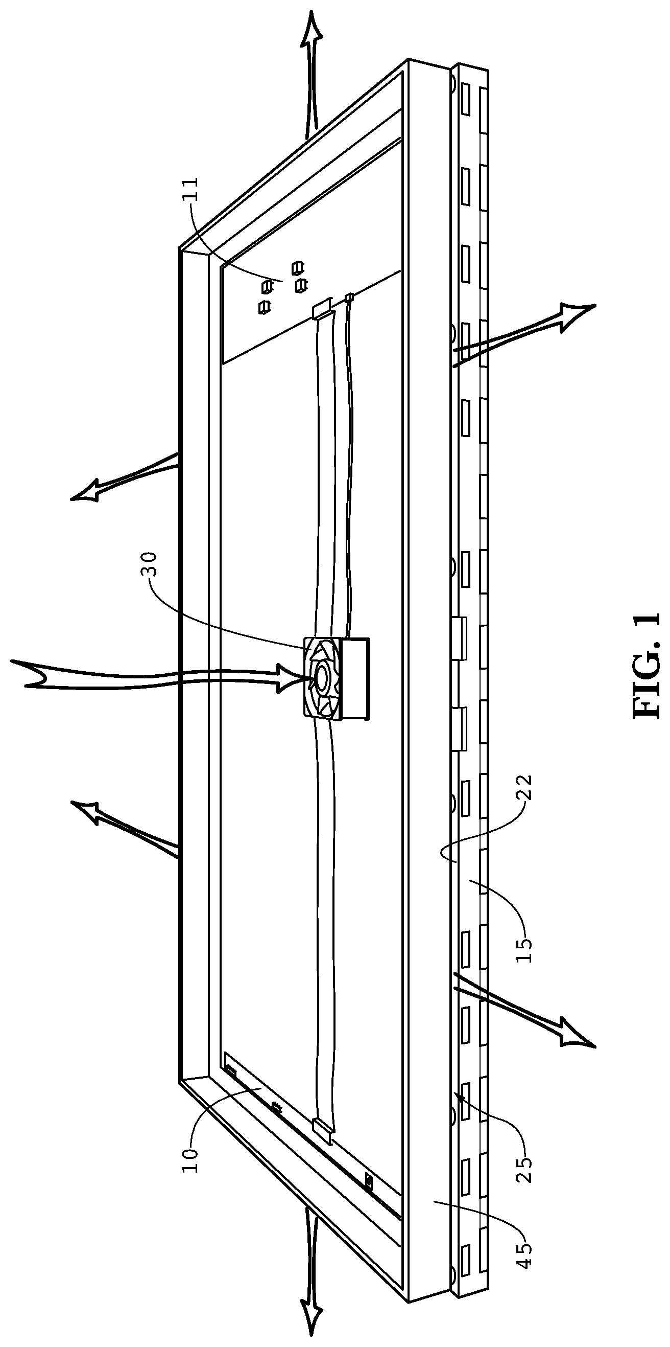
FIG. 1 is a rear perspective view of an exemplary back pan cooling assembly.
FIG. 2 is a sectional view of the embodiment shown in FIG. 1.
DETAILED DESCRIPTION
The invention is described more fully hereinafter with reference to the accompanying drawings, in which exemplary embodiments of the invention are shown. This invention may, however, be embodied in many different forms and should not be construed as limited to the exemplary embodiments set forth herein. Rather, these embodiments are provided so that this disclosure will be thorough and complete, and will fully convey the scope of the invention to those skilled in the art. In the drawings, the size and relative sizes of layers and regions may be exaggerated for clarity.
The terminology used herein is for the purpose of describing particular embodiments only and is not intended to be limiting of the invention. As used herein, the singular forms "a", "an" and "the" are intended to include the plural forms as well, unless the context clearly indicates otherwise. It will be further understood that the terms "comprises" and/or "comprising," when used in this specification, specify the presence of stated features, integers, steps, operations, elements, and/or components, but do not preclude the presence or addition of one or more other features, integers, steps, operations, elements, components, and/or groups thereof.
Embodiments of the invention are described herein with reference to illustrations that are schematic illustrations of idealized embodiments (and intermediate structures) of the invention. As such, variations from the shapes of the illustrations as a result, for example, of manufacturing techniques and/or tolerances, are to be expected. Thus, embodiments of the invention should not be construed as limited to the particular shapes of regions illustrated herein but are to include deviations in shapes that result, for example, from manufacturing.
Unless otherwise defined, all terms (including technical and scientific terms) used herein have the same meaning as commonly understood by one of ordinary skill in the art to which this invention belongs. It will be further understood that terms, such as those defined in commonly used dictionaries, should be interpreted as having a meaning that is consistent with their meaning in the context of the relevant art and will not be interpreted in an idealized or overly formal sense unless expressly so defined herein.
FIG. 1 is a rear perspective view of an exemplary back pan cooling assembly where the rear cover 100 has been removed. An electronic display 15 is provided on the bottom with an exemplary cooling back pan 45 positioned on the top. The electronic display 15 contains a rear pan 22 on the rear surface of the electronic display 15 (i.e. on the side opposing an intended observer). The rear pan 22 is often a component in mass-manufactured electronic displays and typically provides mounts for electronic subassemblies or housings to go with the electronic display. In some embodiments, the rear pan 22 is metallic. As used herein, the term `rear pan` does not require that the pan is actually the one that came with the originally mass-manufactured display, as this component may be upgraded from its originally mass-manufactured form by downstream manufacturers.
Here, electronic components 10 and 11 for driving the electronic display 15 are fastened to the cooling back pan 45. In an exemplary embodiment, the electronic components 10 and 11 may be placed in conductive thermal communication with the cooling back pan 22. The electronic components 10 and 11 may contain any one of the following: timing and control boards (TCON), power supplies, video cards/drivers/players, input/output interfaces, antennas, wireless receivers, modems, local electronic storage, and CPU/microprocessors.
The space between the rear pan 22 and the exemplary cooling back pan 45 defines an air gap 25. The fan 30 is positioned so as to cause a flow of ambient cooling air through the gap 25, in order to cool both the rear pan 22 and the cooling back pan 45. The fan 30 preferably draws ambient air from around the display housing, without letting the air enter other portions of the display housing, especially the portions of the cooling back pan 45 which contain the electronic components 10 and 11 (i.e. the portions sealed off between the cooling back pan 45 and the rear cover 100). In other words, the fan 30 is preferably placed in sealed gaseous communication with the surrounding ambient air and the gap 25 such that ambient air can pass through the fan 30 and gap 25 without entering the area sealed by the cooling back pan 45 and rear cover 100.
In at least one embodiment, a port 150 is provided which provides sealed gaseous communication between the ambient air surrounding the display housing and the fan 30. Once forced through the gap 25, the cooling air can exit any portion of the perimeter of the rear pan 22 and cooling back pan 45 assemblies, and eventually is exhausted out of the edges of the display housing. In other words, the gap 25 preferably extends to all four edges of the display housing and allows ambient air to enter/exit the gap 25 along all four edges of the rear pan 22 and cooling back pan 45.
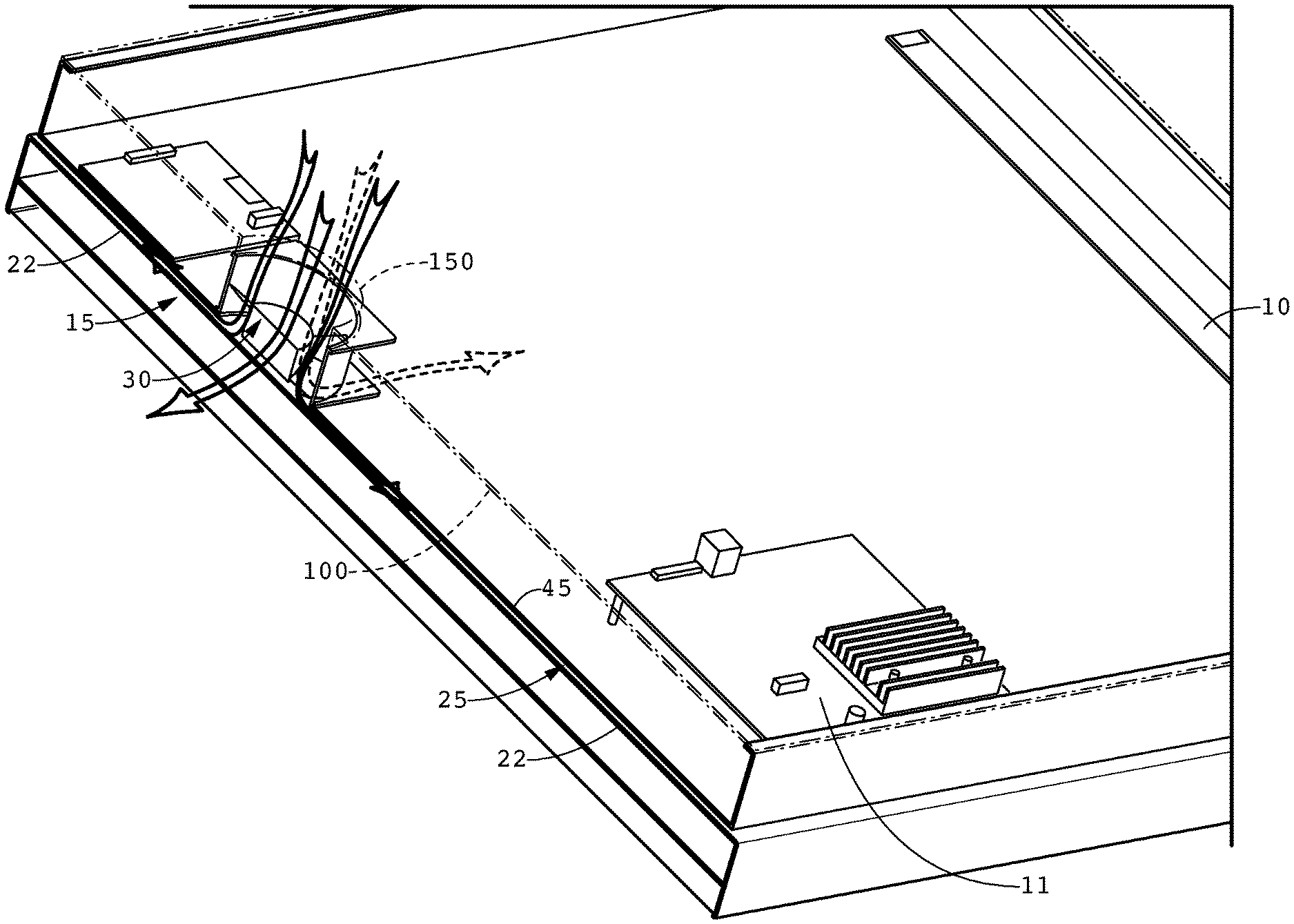
FIG. 2 is a sectional view of the embodiment shown in FIG. 1.
As can be observed, the cooling back pan 45 can be used to mount any number of specialized electrical components 10 and 11 which may be required for the end-use of any electronic display. At the same time, the cooling back pan 45 can help remove heat from the electronic components 10 and 11 as well as the rear pan 22, without exposing the sensitive components to ambient air (which may contain dirt, dust, or contaminates).
It should be noted that although a single fan 30 is shown, this is not required by any embodiment as there can be multiple fans positioned on the cooling back pan 45 in other embodiments. Also, although an exemplary embodiment uses the fan 30 to push the cooling air into the gap 25, alternative embodiments could also be used to draw air from the edges of the display housing, through the gap 25, and exhaust the air through the port 150. It should also be noted that additional fans may be positioned within the cooling back pan 45 in order to circulate air around the interior of the cooling back pan 45, without mixing with the ambient air.
It should also be noted that it is preferable to place the fan 30 near the center of the cooling back pan 45, although this is not required. It may be preferable in some instances to place the fan 30 closer to the horizontal top edge of the cooling back pan 45 (as shown in FIG. 2), as the heat generated by the display assembly tends to rise where additional flow rates of cooling air would be beneficial in this area. In most cases, if using only one fan 30, it may be preferable to place the fan near the vertically-drawn centerline of the cooling back pan 45.
As used herein, the term `electronic display` is any electronic assembly for generating an image to a viewer. The term specifically includes, but is not limited to: liquid crystal displays (all types), OLED, light emitting diode (LED), field emitting display (FED), light emitting polymer (LEP), organic electro luminescence (OEL), plasma displays, and any other type of thin/flat panel display. In an exemplary embodiment, the electronic display 15 comprises an LED edge lit LCD display where the LED backlight is placed in conductive thermal communication with the rear pan 22. In another exemplary embodiment, the electronic display 15 comprises an LED direct backlit LCD display where the rear pan 22 is provided as the rear surface of the direct LED backlight.
Having shown and described a preferred embodiment of the invention, those skilled in the art will realize that many variations and modifications may be made to affect the described invention and still be within the scope of the claimed invention. Additionally, many of the elements indicated above may be altered or replaced by different elements which will provide the same result and fall within the spirit of the claimed invention. It is the intention, therefore, to limit the invention only as indicated by the scope of the claims.
* * * * *
D00000
D00001
D00002
XML
uspto.report is an independent third-party trademark research tool that is not affiliated, endorsed, or sponsored by the United States Patent and Trademark Office (USPTO) or any other governmental organization. The information provided by uspto.report is based on publicly available data at the time of writing and is intended for informational purposes only.
While we strive to provide accurate and up-to-date information, we do not guarantee the accuracy, completeness, reliability, or suitability of the information displayed on this site. The use of this site is at your own risk. Any reliance you place on such information is therefore strictly at your own risk.
All official trademark data, including owner information, should be verified by visiting the official USPTO website at www.uspto.gov. This site is not intended to replace professional legal advice and should not be used as a substitute for consulting with a legal professional who is knowledgeable about trademark law.