Optical lens system
Cheng , et al.
U.S. patent number 10,656,397 [Application Number 14/981,691] was granted by the patent office on 2020-05-19 for optical lens system. This patent grant is currently assigned to YOUNG OPTICS INC.. The grantee listed for this patent is Young Optics Inc.. Invention is credited to Hung-You Cheng, Yu-Hung Chou, Wei-Hao Huang, Ching-Lung Lai, Yi-Hua Lin.


View All Diagrams
| United States Patent | 10,656,397 |
| Cheng , et al. | May 19, 2020 |
Optical lens system
Abstract
An optical lens system includes, in order from a magnified side to a minified side, a first lens group and a second lens group. The first lens group of negative refractive power has at least one aspheric surface, and the second lens group of positive refractive power has at least one aspheric surface. Each of the lenses in the optical lens system is a singlet lens, and the condition: TE.sub.(.lamda.=365)>70% is satisfied, where TE.sub.(.lamda.=365) denotes an overall transmittance of all of the lenses in the optical lens system measured at a wavelength of 365 nm.
| Inventors: | Cheng; Hung-You (Hsinchu, TW), Chou; Yu-Hung (Hsinchu, TW), Lai; Ching-Lung (Hsinchu, TW), Lin; Yi-Hua (Hsinchu, TW), Huang; Wei-Hao (Hsinchu, TW) | ||||||||||
|---|---|---|---|---|---|---|---|---|---|---|---|
| Applicant: |
|
||||||||||
| Assignee: | YOUNG OPTICS INC. (Hsinchu
Science Park, TW) |
||||||||||
| Family ID: | 57602164 | ||||||||||
| Appl. No.: | 14/981,691 | ||||||||||
| Filed: | December 28, 2015 |
Prior Publication Data
| Document Identifier | Publication Date | |
|---|---|---|
| US 20160377844 A1 | Dec 29, 2016 | |
Related U.S. Patent Documents
| Application Number | Filing Date | Patent Number | Issue Date | ||
|---|---|---|---|---|---|
| 14750569 | Jun 25, 2015 | ||||
| Current U.S. Class: | 1/1 |
| Current CPC Class: | G02B 13/143 (20130101); G02B 13/04 (20130101) |
| Current International Class: | G02B 13/14 (20060101); G02B 9/64 (20060101); G02B 13/18 (20060101); G02B 7/04 (20060101); G02B 13/04 (20060101); G02B 27/00 (20060101) |
| Field of Search: | ;359/350,354-357,432,642,648-649,728,749,754,691,717,793 |
References Cited [Referenced By]
U.S. Patent Documents
| 4770477 | September 1988 | Shafer |
| 5930032 | July 1999 | Maruyama et al. |
| 5999310 | December 1999 | Shafer et al. |
| 6115175 | September 2000 | Maruyama et al. |
| 6956694 | October 2005 | Shafer et al. |
| 7057804 | June 2006 | Tada et al. |
| 7599127 | October 2009 | Muratani |
| 7768719 | August 2010 | Jung |
| 8279527 | October 2012 | Lin |
| 8498066 | July 2013 | Liu et al. |
| 9261670 | February 2016 | Lai |
| 2003/0155482 | August 2003 | Moellmann |
| 2006/0077564 | April 2006 | Baba |
| 2009/0296201 | December 2009 | Caldwell |
| 2013/0070123 | March 2013 | Imaoka |
| 2014/0185143 | July 2014 | Kubota |
| 2014/0185144 | July 2014 | Kubota |
| 2016/0154224 | June 2016 | Imai |
Attorney, Agent or Firm: Muncy, Geissler, Olds & Lowe, P.C.
Parent Case Text
CROSS-REFERENCE TO RELATED APPLICATIONS
This application is a continuation-in-part of application Ser. No. 14/750,569, filed on Jun. 25, 2015, the entire disclosure of which is incorporated herein by reference.
Claims
What is claimed is:
1. An optical lens system using ultraviolet for imaging, comprising in order from a magnified side to a minified side: a first lens group of negative refractive power having at least one aspheric lens; and a second lens group of positive refractive power having at least one aspheric lens, wherein each of the lenses in the optical lens system is a singlet lens, and the condition: TE.sub.(.lamda.=365)>70% is satisfied, where TE.sub.(.lamda.=365) denotes an overall transmittance of all of the lenses in the optical lens system measured at a wavelength of 365 nm and is equal to a product of respective internal transmittances of all of the lenses measured at a wavelength of 365 nm.
2. The optical lens system as claimed in claim 1, wherein the condition: T.sub.(.lamda.=365)>80% is satisfied, where T.sub.(.lamda.=365) denotes a transmittance of a lens material forming each of the lenses in the optical lens system, the transmittance of the lens material being measured at a wavelength of 365 nm and a thickness of 10 mm.
3. The optical lens system as claimed in claim 1, wherein the condition: G/N<0.2 is satisfied, where N denotes a total number of the lenses in the optical lens system, and G denotes a number of the lenses formed of a lens material having a transmittance of smaller than 87% in the optical lens system, the transmittance of the lens material being measured at a wavelength of 365 nm and a thickness of 10 mm.
4. The optical lens system as claimed in claim 1, wherein at least one lens in the optical system is formed of a lens material having a transmittance of smaller than 87%, the transmittance of the lens material being measured at a wavelength of 365 nm and a thickness of 10 mm.
5. The optical lens system as claimed in claim 1, wherein an F number of the optical lens system is larger than 1.7, or an absolute value of a maximum optical distortion of the optical lens system is smaller than 0.2%.
6. The optical lens system as claimed in claim 1, wherein the second lens group comprises at least one lens having negative refractive power and an Abbe number of no more than 39.7.
7. The optical lens system as claimed in claim 1, wherein at least one of the first lens group and the second lens group is moveable during focusing.
8. The optical lens system as claimed in claim 1, wherein the first lens group comprises in order from a magnified side to a minified side: a first lens of positive refractive power; a second lens of negative refractive power; a third lens of negative refractive power; and a fourth lens of positive refractive power, and the second lens group comprises in order from a magnified side to a minified side: a fifth lens of positive refractive power; a sixth lens of negative refractive power; a seventh lens of negative refractive power; a eighth lens of positive refractive power; and a ninth lens of positive refractive power.
9. The optical lens system as claimed in claim 1, wherein the first lens group comprises in order from a magnified side to a minified side: a first lens of negative refractive power; a second lens of positive refractive power; a third lens of negative refractive power; a fourth lens of negative refractive power; and a fifth lens of positive refractive power, and the second lens group comprises in order from a magnified side to a minified side: a sixth lens of positive refractive power; a seventh lens of positive refractive power; a eighth lens of negative refractive power; a ninth lens of positive refractive power; and a tenth lens of positive refractive power.
10. The optical lens system as claimed in claim 1, wherein the first lens group comprises in order from a magnified side to a minified side: a first lens of negative refractive power; a second lens of positive refractive power; a third lens of positive refractive power; a fourth lens of negative refractive power; a fifth lens of negative refractive power; and a sixth lens of positive refractive power, and the second lens group comprises in order from a magnified side to a minified side: a seventh lens of positive refractive power; a eighth lens of positive refractive power; a ninth lens of negative refractive power; a tenth lens of positive refractive power; and a eleventh lens of positive refractive power.
11. An optical lens system comprising in order from a magnified side to a minified side: a first lens group of negative refractive power; and a second lens group of positive refractive power, wherein the optical lens system has at least one aspheric lens, each of the lenses in the optical lens system is a singlet lens, and the conditions: T.sub.(.lamda.=365)>80%; and TE.sub.(.lamda.=365)>70% are satisfied, where T.sub.(.lamda.=365) denotes a transmittance of each of the lenses in the optical lens system measured at a wavelength of 365 nm, and TE.sub.(.lamda.=365) denotes an overall transmittance of all of the lenses in the optical lens system measured at a wavelength of 365 nm and is equal to a product of respective transmittances of all of the lenses measured at a wavelength of 365 nm.
12. The optical lens system as claimed in claim 11, wherein the condition: G/N<0.2 is satisfied, where N denotes a total number of the lenses in the optical lens system, and G denotes a number of the lenses formed of a lens material having a transmittance of smaller than 87% in the optical lens system, the transmittance of the lens material being measured at a wavelength of 365 nm and a thickness of 10 mm.
13. The optical lens system as claimed in claim 11, wherein at least one lens in the optical system is formed of a lens material having a transmittance of smaller than 87%, the transmittance of the lens material being measured at a wavelength of 365 nm and a thickness of 10 mm.
14. The optical lens system as claimed in claim 11, wherein an F number of the optical lens system is larger than 1.7, or an absolute value of a maximum optical distortion of the optical lens system is smaller than 0.2%.
15. The optical lens system as claimed in claim 11, wherein the second lens group comprises at least one lens having negative refractive power and an Abbe number of no more than 39.7.
16. The optical lens system as claimed in claim 11, wherein at least one of the first lens group and the second lens group is moveable during focusing.
17. The optical lens system as claimed in claim 11, wherein the first lens group comprises in order from a magnified side to a minified side: a first lens of positive refractive power; a second lens of negative refractive power; a third lens of negative refractive power; and a fourth lens of positive refractive power, and the second lens group comprises in order from a magnified side to a minified side: a fifth lens of positive refractive power; a sixth lens of negative refractive power; a seventh lens of negative refractive power; a eighth lens of positive refractive power; and a ninth lens of positive refractive power.
18. The optical lens system as claimed in claim 11, wherein the first lens group comprises in order from a magnified side to a minified side: a first lens of negative refractive power; a second lens of positive refractive power; a third lens of negative refractive power; a fourth lens of negative refractive power; and a fifth lens of positive refractive power, and the second lens group comprises in order from a magnified side to a minified side: a sixth lens of positive refractive power; a seventh lens of positive refractive power; a eighth lens of negative refractive power; a ninth lens of positive refractive power; and a tenth lens of positive refractive power.
19. The optical lens system as claimed in claim 11, wherein the first lens group comprises in order from a magnified side to a minified side: a first lens of negative refractive power; a second lens of positive refractive power; a third lens of positive refractive power; a fourth lens of negative refractive power; a fifth lens of negative refractive power; and a sixth lens of positive refractive power, and the second lens group comprises in order from a magnified side to a minified side: a seventh lens of positive refractive power; a eighth lens of positive refractive power; a ninth lens of negative refractive power; a tenth lens of positive refractive power; and a eleventh lens of positive refractive power.
Description
BACKGROUND OF THE INVENTION
a. Field of the Invention
The invention relates generally to an optical lens system, and more particularly to an optical lens system adapted to transmit short wavelength light for imaging purpose.
b. Description of the Related Art
Generally, an optical lens system that uses short wavelength light as a light source is favorable for forming an image of fine patterns, since the size of the smallest spot image that can be resolved is in proportion to the wavelength. However, the optical lens system using short wavelength light is difficult to achieve a high light transmittance and may cause considerable chromatic aberrations that increase as the wavelength decreases. Therefore, it is desirable to provide a high-performance optical lens system that has an improved light transmittance and is favorable for correcting chromatic aberrations.
BRIEF SUMMARY OF THE INVENTION
According to one aspect of the present disclosure, an optical lens system using ultraviolet for imaging includes, in order from a magnified side to a minified side, a first lens group and a second lens group. The first lens group of negative refractive power has at least one aspheric surface, and the second lens group of positive refractive power has at least one aspheric surface. Each of the lenses in the optical lens system is a singlet lens, and the condition: TE.sub.(.lamda.=365)>70% is satisfied, where TE.sub.(.lamda.=365) denotes an overall transmittance of all of the lenses in the optical lens system measured at a wavelength of 365 nm.
According to another aspect of the present disclosure, an optical lens system includes, in order from a magnified side to a minified side, a first lens group of negative refractive power and a second lens group of positive refractive power. The optical lens system has at least one aspheric surface, and the conditions: T.sub.(.lamda.=365)>80%; and
TE.sub.(.lamda.=365)>70% are satisfied, where T.sub.(.lamda.=365) denotes a transmittance of a lens material forming each of the lenses in the optical lens system, with the transmittance of the lens material being measured at a wavelength of 365 nm and a thickness of 10 mm, and TE.sub.(.lamda.=365) denotes an overall transmittance of all of the lenses in the optical lens system measured at a wavelength of 365 nm.
Other objectives, features and advantages of the invention will be further understood from the further technological features disclosed by the embodiments of the invention wherein there are shown and described preferred embodiments of this invention, simply by way of illustration of modes best suited to carry out the invention.
BRIEF DESCRIPTION OF THE DRAWINGS
FIG. 1 shows a schematic diagram illustrating an optical lens system according to an embodiment of the invention.
FIGS. 2, 3A and 3B show optical simulation results of the optical lens system shown in FIG. 1. FIG. 2 illustrates modulation transfer function (MTF) curves, FIG. 3A illustrates astigmatic field curves, and FIG. 3B illustrates percentage distortion curves.
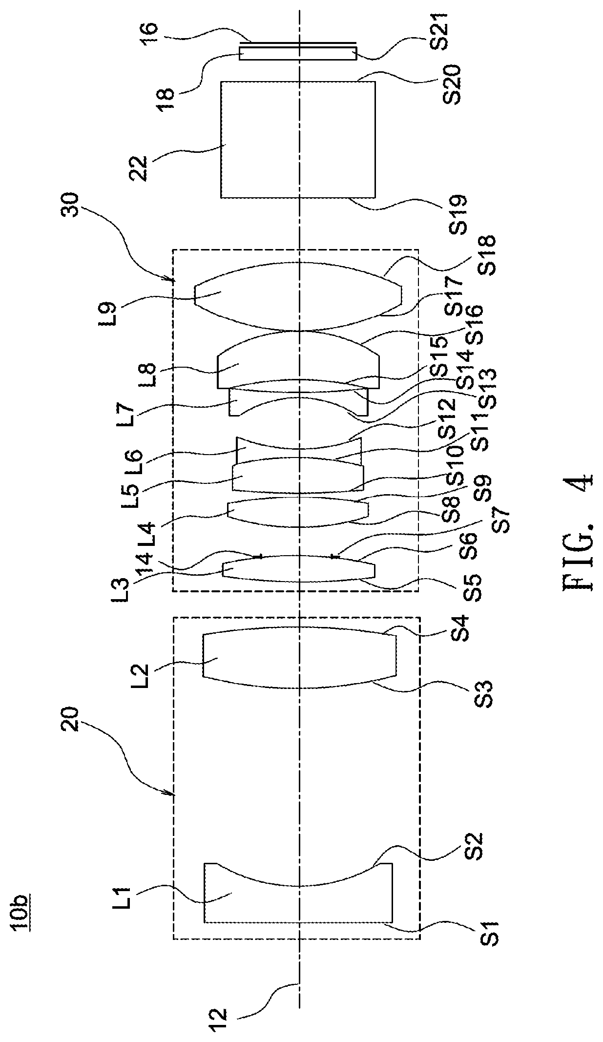
FIG. 4 shows a schematic diagram illustrating an optical lens system according to another embodiment of the invention.
FIGS. 5, 6A and 6B show optical simulation results of the optical lens system shown in FIG. 4. FIG. 5 illustrates modulation transfer function (MTF) curves, FIG. 6A illustrates astigmatic field curves, and FIG. 6B illustrates percentage distortion curves.
FIG. 7 shows a schematic diagram illustrating an optical lens system according to another embodiment of the invention.
FIGS. 8, 9A and 9B show optical simulation results of the optical lens system shown in FIG. 7. FIG. 8 illustrates modulation transfer function (MTF) curves, FIG. 9A illustrates astigmatic field curves, and FIG. 9B illustrates percentage distortion curves.
FIG. 10 shows a schematic diagram illustrating an optical lens system according to another embodiment of the invention.
FIGS. 11, 12A and 12B show optical simulation results of the optical lens system shown in FIG. 10. FIG. 11 illustrates modulation transfer function (MTF) curves, FIG. 12A illustrates astigmatic field curves, and FIG. 12B illustrates percentage distortion curves.
FIG. 13 shows a schematic diagram illustrating an optical lens system according to another embodiment of the invention.
FIGS. 14, 15A and 15B show optical simulation results of the optical lens system shown in FIG. 13. FIG. 14 illustrates modulation transfer function (MTF) curves, FIG. 15A illustrates astigmatic field curves, and FIG. 15B illustrates percentage distortion curves.
FIG. 16 shows a schematic diagram illustrating an optical lens system according to another embodiment of the invention.
FIGS. 17, 18A and 18B show optical simulation results of the optical lens system shown in FIG. 16. FIG. 17 illustrates modulation transfer function (MTF) curves, FIG. 18A illustrates astigmatic field curves, and FIG. 18B illustrates percentage distortion curves.
FIG. 19 shows a schematic diagram illustrating an optical lens system according to another embodiment of the invention.
FIGS. 20, 21A and 21B show optical simulation results of the optical lens system shown in FIG. 19. FIG. 20 illustrates modulation transfer function (MTF) curves, FIG. 21A illustrates astigmatic field curves, and FIG. 21B illustrates percentage distortion curves.
FIG. 22 shows a schematic diagram illustrating an optical lens system according to another embodiment of the invention.
FIGS. 23, 24A and 24B show optical simulation results of the optical lens system shown in FIG. 22. FIG. 23 illustrates modulation transfer function (MTF) curves, FIG. 24A illustrates astigmatic field curves, and FIG. 24B illustrates percentage distortion curves.
FIG. 25 shows a schematic diagram illustrating an optical lens system according to another embodiment of the invention.
FIGS. 26, 27A and 27B show optical simulation results of the optical lens system shown in FIG. 25. FIG. 26 illustrates modulation transfer function (MTF) curves, FIG. 27A illustrates astigmatic field curves, and FIG. 27B illustrates percentage distortion curves.
FIG. 28 shows a schematic diagram illustrating an optical lens system according to another embodiment of the invention.
FIGS. 29, 30A and 30B show optical simulation results of the optical lens system shown in FIG. 28. FIG. 29 illustrates modulation transfer function (MTF) curves, FIG. 30A illustrates astigmatic field curves, and FIG. 30B illustrates percentage distortion curves.
FIG. 31 shows a schematic diagram illustrating an optical lens system according to another embodiment of the invention.
FIGS. 32, 33A and 33B show optical simulation results of the optical lens system shown in FIG. 31. FIG. 32 illustrates modulation transfer function (MTF) curves, FIG. 33A illustrates astigmatic field curves, and FIG. 33B illustrates percentage distortion curves.
FIG. 34 shows a schematic diagram illustrating an optical lens system according to another embodiment of the invention.
FIGS. 35, 36A and 36B show optical simulation results of the optical lens system shown in FIG. 34. FIG. 35 illustrates modulation transfer function (MTF) curves, FIG. 36A illustrates astigmatic field curves, and FIG. 36B illustrates percentage distortion curves.
FIG. 37 shows a schematic diagram illustrating an optical lens system according to another embodiment of the invention.
FIGS. 38, 39A and 39B show optical simulation results of the optical lens system shown in FIG. 37. FIG. 38 illustrates modulation transfer function (MTF) curves, FIG. 39A illustrates astigmatic field curves, and FIG. 39B illustrates percentage distortion curves.
DETAILED DESCRIPTION OF THE INVENTION
In the following detailed description of the preferred embodiments, reference is made to the accompanying drawings which form a part hereof, and in which are shown by way of illustration specific embodiments in which the invention may be practiced. In this regard, directional terminology, such as "top," "bottom," "front," "back," etc., is used with reference to the orientation of the Figure(s) being described. The components of the invention can be positioned in a number of different orientations. As such, the directional terminology is used for purposes of illustration and is in no way limiting. On the other hand, the drawings are only schematic and the sizes of components may be exaggerated for clarity. It is to be understood that other embodiments may be utilized and structural changes may be made without departing from the scope of the invention. Also, it is to be understood that the phraseology and terminology used herein are for the purpose of description and should not be regarded as limiting. The use of "including," "comprising," or "having" and variations thereof herein is meant to encompass the items listed thereafter and equivalents thereof as well as additional items. Unless limited otherwise, the terms "connected," "coupled," and "mounted" and variations thereof herein are used broadly and encompass direct and indirect connections, couplings, and mountings. Similarly, the terms "facing," "faces" and variations thereof herein are used broadly and encompass direct and indirect facing, and "adjacent to" and variations thereof herein are used broadly and encompass directly and indirectly "adjacent to". Therefore, the description of "A" component facing "B" component herein may contain the situations that "A" component directly faces "B" component or one or more additional components are between "A" component and "B" component. Also, the description of "A" component "adjacent to" "B" component herein may contain the situations that "A" component is directly "adjacent to" "B" component or one or more additional components are between "A" component and "B" component. Accordingly, the drawings and descriptions will be regarded as illustrative in nature and not as restrictive.
An optical lens system according to an embodiment of the invention may include a first lens group 20 of positive refractive power and a second lens group 30 of positive refractive power. The second lens group 30 may include at least one aspherical lens surface for correcting different kinds of optical aberrations such as spherical aberration, coma, astigmatism, field curvature, and image distortion. Besides, the second lens group 30 may include at least one cemented lens to balance chromatic aberration. A spatial light modulator 16, for example, a digital micro-mirror device (DMD), selectively reflects illumination light to produce image light, and the image light may pass through a cover plate 18, a deflection prism 22, the second lens group 30, and the first lens group 20 in succession, and then the image light is projected onto an object (not shown).
In one embodiment, each of the lenses in the optical lens system may be made of glass. When the lens is made of glass, the distribution of the refractive power of the optical lens system may be more flexible to design, and the glass material is not sensitive to temperature variations to ensure competent resolution of the optical lens system under different ambient temperatures. Further, because the second lens group 30 may include at least one aspherical lens surface, more controllable variables are obtained, and the aberration is reduced, as well as the number of required lenses can be minified on constructing an optical lens system to reduce the total track length.
In one embodiment, the optical lens system may use short wavelength light such as blue light or ultraviolet as a light source. The optical lens system according to one embodiment may satisfy the following condition: T.sub.(.lamda.=400)>95%; and
TE.sub.(.lamda.=400)>94%, where T.sub.(.lamda.=400) denotes a transmittance of a lens material forming each of the lenses in the optical lens system, with the transmittance of the lens material being measured at a wavelength of 400 nm and a thickness of 10 mm, and TE.sub.(.lamda.=400) denotes an overall transmittance of all of the lenses in the optical lens system measured at a wavelength of 400 nm.
Further, the optical lens system according to one embodiment may satisfy the following condition: T.sub.(.lamda.=350)>90%; and
TE.sub.(.lamda.=350)>80%, where T.sub.(.lamda.=350) denotes a transmittance of a lens material forming each of the lenses in the optical lens system, with the transmittance of the lens material being measured at a wavelength of 350 nm and a thickness of 10 mm, and TE.sub.(.lamda.=350) denotes an overall transmittance of all of the lenses in the optical lens system measured at a wavelength of 350 nm.
In one embodiment, the optical lens system may satisfy the following condition:
C/N.gtoreq.0.7, where N denotes a total number of the lenses in the optical lens system, and C denotes a number of the lenses having an Abbe number of larger than 40 in the optical lens system.
According to the above embodiments, the optical lens system is featured with good correction ability, high light transmittance and improved image quality.
A first design example of an optical lens system 10a is described in detail below with reference to FIG. 1. As illustrated in FIG. 1, the first lens group 20 includes two lenses L1 and L2 arranged in order, along an optical axis 12, from a magnified side (on the left of FIG. 1) to a minified side (on the right of FIG. 1). The second lens group 30 includes seven lenses L3, L4, L5, L6, L7, L8 and L9 arranged in order, along the optical axis 12, from the magnified side to the minified side. The refractive powers of the lens L1, L2, L3, L4, L5, L6, L7, L8 and L9 are negative, positive, positive, positive, positive, negative, negative, positive and positive, respectively. The lens L9 of the second lens group 30 may have at least one aspheric surface. The lens L5 and lens L6 are integrated as one piece to form a cemented lens. An aperture stop 14 is located between the lens L3 and the lens L4. The lens L1 has a convex magnified-side surface S1 and a concave minified-side surface S2, the lens L2 has a convex magnified-side surface S3 and a convex minified-side surface S4, the lens L3 has a convex magnified-side surface S5 and a convex minified-side surface S6, the lens L4 has a convex magnified-side surface S8 and a concave minified-side surface S9, the lens L5 has a convex magnified-side surface S10, the lens L6 has a concave magnified-side surface S11 and a concave minified-side surface S12, the lens L7 has a concave magnified-side surface S13 and a concave minified-side surface S14, the lens L8 has a concave magnified-side surface S15 and a convex minified-side surface S16, and the lens L9 has a convex magnified-side surface S17 and a convex minified-side surface S18.
According to the optical lens system of the present disclosure, each of a magnified-side and a minified-side surface of a lens has a paraxial region and a peripheral region. The paraxial region refers to the region of the surface where light rays travel close to an optical axis and the peripheral region refers to the region of the surface where light rays travel away from the optical axis. Particularly, when a lens has a convex surface, it may indicate that the surface is convex at the paraxial region; and when the lens has a concave surface, it may indicate that the surface is concave at the paraxial region.
The detailed optical data of the first example are shown in Table 1 below.
TABLE-US-00001 TABLE 1 Applied to a wavelength of 405 .+-. 25 nm Effective focal length of the optical lens system F = 20.7095 mm Effective focal length of the first lens group F1 = 74.2252 mm Effective focal length of the second lens group F2 = 32.2465 mm thick- radius ness refractive Abbe Refractive Surface (mm) (mm) index number power Shape S1 444.281 3.80 1.55 45.80 L1(-) convex S2 17.495 19.90 concave S3 37.652 3.62 1.74 52.60 L2(+) convex S4 -104.735 6.27 convex S5 68.171 2.32 1.74 52.60 L3(+) convex S6 -94.965 0.00 convex S7 (stop) INF 4.94 S8 31.467 2.03 1.50 81.60 L4(+) convex S9 102.715 0.56 concave S10 24.415 4.14 1.50 81.60 L5(+) convex S11 -44.318 0.80 1.63 35.70 L6(-) concave S12 15.460 3.48 concave S13 -10.904 0.80 1.63 35.70 L7(-) concave S14 79.930 1.46 concave S15 -29.862 4.98 1.74 52.60 L8(+) concave S16 -14.871 0.10 convex S17 25.045 6.95 1.50 81.50 L9(+) convex S18 -20.498 6.26 convex S19 INF 12.00 1.52 64.20 S20 INF 2.00 S21 INF 1.10 1.52 64.20
Further, the aspheric surface satisfies the following equation:
'.times..times.'.times..times..times. ##EQU00001## where x denotes a displacement from the vertex of a lens in the direction of the optical axis 12, c' denotes a reciprocal of the radius of curvature at the vertex of a lens (approaching the optical axis 12), K denotes a Conic constant, y denotes a height (distance in the direction perpendicular to the optical axis 12) of the aspheric surface, and A, B, C, D, E, F and G are aspheric coefficients. The values of aspheric coefficients and Conic constant of each lens surface are listed in Table 2.
TABLE-US-00002 TABLE 2 Lens surface S17 S18 K 1.10071 -2.97277 A -3.88383E-05 -3.03061E-05 B -4.06842E-08 -1.30204E-07 C -6.76742E-09 -1.88563E-09 D 2.56796E-10 1.39610E-10 E -4.56285E-12 -2.77246E-12 F 3.80755E-14 2.33529E-14 G -1.24546E-16 -7.51743E-17
Table 3 lists the internal transmittance of each of the lenses L1-L9 of the optical lens system 10a and the overall transmittance of all of the lenses L1-L9 at different wavelengths. As used herein, the term "internal transmittance" of a lens means a transmittance of a lens material forming such lens, and the transmittance of the lens material is measured at a thickness of 10 mm and a selected wavelength specified in the table. Table 3 clearly shows each of the lenses L1-L9 may have a light transmittance of larger than 95% at a wavelength of 380 nm or 400 nm.
TABLE-US-00003 TABLE 3 Internal transmittance 380 nm 400 nm Lens L1 97.9% 99.4% Lens L2 97.6% 99.0% Lens L3 98.5% 99.3% Lens L4 99.9% 99.9% Lens L5 99.8% 99.8% Lens L6 98.1% 99.6% Lens L7 98.1% 99.6% Lens L8 96.8% 98.6% Lens L9 99.6% 99.7% Total 86.9% 94.8%
FIGS. 2, 3A and 3B show optical simulation results of the optical lens system shown in FIG. 1. FIG. 2 illustrates modulation transfer function (MTF) curves, FIG. 3A illustrates astigmatic field curves, and FIG. 3B illustrates percentage distortion curves. As shown in FIGS. 2, 3A and 3B, the MTF at a spatial frequency of 93 lp/mm is larger than 75%, and the optical distortion is smaller than 0.1%.
A second design example of an optical lens system 10b including nine lenses L1-L9 is described in detail below with reference to FIG. 4. The detailed optical data of the second example are shown in Table 4, and the aspheric surface data are shown in Table 5 below.
TABLE-US-00004 TABLE 4 Applied to a wavelength of 470 .+-. 25 nm Effective focal length of the optical lens system F = 20.9737 mm Effective focal length of the first lens group F1 = 76.3023 mm Effective focal length of the second lens group F2 = 32.7664 mm thick- radius ness refractive Abbe Refractive Surface (mm) (mm) index number power Shape S1 625.052 3.86 1.55 45.80 L1(-) convex S2 17.747 20.17 concave S3 37.706 6.02 1.74 52.60 L2(+) convex S4 -106.136 4.93 convex S5 69.182 2.32 1.74 52.60 L3(+) convex S6 -97.034 0.13 convex S7 (stop) INF 3.30 S8 31.437 2.12 1.50 81.60 L4(+) convex S9 105.976 0.67 concave S10 24.471 4.14 1.50 81.60 L5(+) convex S11 -30.954 0.80 1.63 35.70 L6(-) concave S12 15.305 5.37 concave S13 -10.997 0.80 1.63 35.70 L7(-) concave S14 77.039 1.12 concave S15 -30.153 5.10 1.74 52.60 L8(+) concave S16 -14.755 0.10 convex S17 24.988 6.95 1.50 81.50 L9(+) convex S18 -20.407 6.68 convex S19 INF 12.00 1.52 64.20 S20 INF 2.00 S21 INF 1.10 1.52 64.20
TABLE-US-00005 TABLE 5 Lens surface S17 S18 K 1.71870 -3.21861 A -3.25263E-05 -2.71939E-05 B -1.35733E-08 -2.25391E-08 C -5.89587E-09 -1.52209E-09 D 2.66412E-10 1.40539E-10 E -4.58516E-12 -2.71012E-12 F 3.78333E-14 2.40216E-14 G -1.18483E-16 -7.75110E-17
Table 6 lists the internal transmittance of each of the lenses L1-L9 of the optical lens system 10b and the overall transmittance of all of the lenses L1-L9 at different wavelengths. Table 6 clearly shows each of the lenses L1-L9 may have an internal transmittance of larger than 95% at a wavelength of 400 nm or 460 nm.
TABLE-US-00006 TABLE 6 Internal transmittance 400 nm 460 nm Lens L1 99.4% 99.8% Lens L2 98.3% 99.5% Lens L3 99.3% 99.8% Lens L4 99.9% 99.9% Lens L5 99.8% 99.8% Lens L6 99.6% 99.9% Lens L7 99.6% 99.9% Lens L8 98.5% 99.5% Lens L9 99.7% 99.7% Total 94.1% 97.9%
FIGS. 5, 6A and 6B show optical simulation results of the optical lens system shown in FIG. 4. FIG. 5 illustrates modulation transfer function (MTF) curves, FIG. 6A illustrates astigmatic field curves, and FIG. 6B illustrates percentage distortion curves. As shown in FIGS. 5, 6A and 6B, the MTF at a spatial frequency of 93 lp/mm is larger than 75%, and the optical distortion is smaller than 0.1%.
A third design example of an optical lens system 10c including nine lenses L1-L9 is described in detail below with reference to FIG. 7. The detailed optical data of the second example are shown in Table 7, and the aspheric surface data are shown in Table 8 below.
TABLE-US-00007 TABLE 7 Applied to a wavelength of 405 .+-. 25 nm Effective focal length of the optical lens system F = 21.3556 mm Effective focal length of the first lens group F1 = 76.9390 mm Effective focal length of the second lens group F2 = 32.5259 mm thick- radius ness refractive Abbe Refractive Surface (mm) (mm) index number power Shape S1 340.136 1.00 1.55 45.80 L1(-) convex S2 17.758 20.48 concave S3 38.668 3.90 1.74 52.60 L2(+) convex S4 -109.511 9.32 convex S5 55.037 2.37 1.74 52.60 L3(+) convex S6 -127.435 0.00 convex S7 (stop) INF 0.10 S8 45.900 2.04 1.50 81.60 L4(+) convex S9 571.706 3.58 concave S10 26.836 4.67 1.50 81.60 L5(+) convex S11 -24.052 0.80 1.63 35.70 L6(-) concave S12 16.821 3.97 concave S13 -11.516 0.80 1.63 35.70 L7(-) concave S14 278.385 1.26 concave S15 -27.830 6.64 1.74 52.60 L8(+) concave S16 -15.936 0.10 convex S17 23.947 5.84 1.50 81.60 L9(+) convex S18 -24.778 6.06 convex S19 INF 12.00 1.52 64.20 S20 INF 2.00 S21 INF 1.10 1.52 64.20
TABLE-US-00008 TABLE 8 Radius S17 S18 K 0.62489 -4.35368 A -3.28231E-05 -2.29932E-05 B -2.68419E-08 -1.16262E-07 C -7.57941E-09 -2.73603E-09 D 2.60161E-10 1.55837E-10 E -4.36140E-12 -2.95646E-12 F 3.44500E-14 2.40146E-14 G -1.09708E-16 -7.68070E-17
Table 9 lists the internal transmittance of each of the lenses L1-L9 of the optical lens system 10c and the overall transmittance of all of the lenses L1-L9 at different wavelengths. Table 9 clearly shows each of the lenses L1-L9 may have an internal transmittance of larger than 95% at a wavelength of 380 nm or 400 nm.
TABLE-US-00009 TABLE 9 Internal transmittance 380 nm 400 nm Lens L1 99.4% 99.8% Lens L2 97.5% 98.9% Lens L3 98.5% 99.3% Lens L4 99.9% 99.9% Lens L5 99.7% 99.8% Lens L6 98.1% 99.6% Lens L7 98.1% 99.6% Lens L8 95.7% 98.1% Lens L9 99.6% 99.7% Total 87.2% 94.7%
FIGS. 8, 9A and 9B show optical simulation results of the optical lens system shown in FIG. 7. FIG. 8 illustrates modulation transfer function (MTF) curves, FIG. 9A illustrates astigmatic field curves, and FIG. 9B illustrates percentage distortion curves. As shown in FIGS. 8, 9A and 9B, the MTF at a spatial frequency of 93 lp/mm is larger than 75%, and the optical distortion is smaller than 0.1%.
A fourth design example of the optical lens system 10d including eight lenses L1-L8 is described in detail below with reference to FIG. 10. The detailed optical data of the first example are shown in Table 10, and the aspheric surface data are shown in Table 11 below.
TABLE-US-00010 TABLE 10 Applied to a wavelength of 405 .+-. 25 nm Effective focal length of the optical lens system F = 18.0912 mm Effective focal length of the first lens group F1 = 56.5119 mm Effective focal length of the second lens group F2 = 27.1366 mm thick- radius ness refractive Abbe Refractive Surface (mm) (mm) index number power Shape S1 -145.942 1.18 1.49 70.20 L1(-) concave S2 19.502 3.53 concave S3 -37.008 7.44 1.75 52.30 L2(+) concave S4 -26.602 19.07 convex S5 20.939 2.95 1.50 81.50 L3(+) convex S6 (stop) 109.747 6.02 concave S7 31.202 3.30 1.70 55.50 L4(+) convex S8 -49.052 4.32 convex S9 -26.587 0.82 1.62 36.30 L5(-) concave S10 21.384 4.15 concave S11 -8.911 0.80 1.62 36.30 L6(-) concave S12 -60.360 4.87 1.75 52.30 L7(+) concave S13 -13.916 0.37 convex S14 23.758 6.79 1.50 81.50 L8(+) convex S15 -20.132 8.77 convex S16 INF 12.00 1.52 64.20 S17 INF 2.00 S18 INF 1.10 1.52 64.20
TABLE-US-00011 TABLE 11 Radius S14 S15 K 0.00000 0.00000 A -2.82044E-05 3.63169E-05 B 2.45762E-08 -2.69222E-08 C -1.00424E-10 2.65369E-10 D -4.13447E-13 -1.10686E-12 E 0.00000E+00 0.00000E+00 F 0.00000E+00 0.00000E+00 G 0.00000E+00 0.00000E+00
Table 12 lists the internal transmittance of each of the lenses L1-L8 of the optical lens system 10d and the overall transmittance of all of the lenses L1-L8 at different wavelengths. Table 12 clearly shows each of the lenses L1-L8 may have an internal transmittance of larger than 95% at a wavelength of 380 nm or 400 nm.
TABLE-US-00012 TABLE 12 Internal transmittance 380 nm 400 nm Lens L1 100.0% 100.0% Lens L2 96.7% 98.5% Lens L3 99.8% 99.9% Lens L4 98.6% 99.4% Lens L5 100.0% 100.0% Lens L6 100.0% 100.0% Lens L7 97.9% 99.0% Lens L8 99.6% 99.7% Total 92.7% 96.4%
FIGS. 11, 12A and 12B show optical simulation results of the optical lens system shown in FIG. 10. FIG. 11 illustrates modulation transfer function (MTF) curves, FIG. 12A illustrates astigmatic field curves, and FIG. 12B illustrates percentage distortion curves. As shown in FIGS. 11, 12A and 12B, the MTF at a spatial frequency of 93 lp/mm is larger than 75%, and the optical distortion is smaller than 0.1%.
A fifth design example of the optical lens system 10e including eight lenses L1-L8 is described in detail below with reference to FIG. 13. The detailed optical data of the first example are shown in Table 13, and the aspheric surface data are shown in Table 14 below.
TABLE-US-00013 TABLE 13 Applied to a wavelength of 405 .+-. 25 nm Effective focal length of the optical lens system F = 19.3228 mm Effective focal length of the first lens group F1 = 62.4585 mm Effective focal length of the second lens group F2 = 28.2227 mm thick- radius ness refractive Abbe Refractive Surface (mm) (mm) index number power Shape S1 15.363 6.97 1.75 52.30 L1(-) convex S2 11.416 3.41 concave S3 53.065 0.80 1.52 52.40 L2(-) convex S4 12.298 20.49 concave S5 30.869 3.45 1.50 81.50 L3(+) convex S6 (stop) -31.948 5.97 convex S7 32.293 3.22 1.73 54.70 L4(+) convex S8 -72.809 4.17 convex S9 -70.595 2.67 1.62 36.30 L5(-) concave S10 24.698 3.67 concave S11 -10.076 0.80 1.62 36.30 L6(-) concave S12 -177.804 5.57 1.60 65.40 L7(+) concave S13 -15.034 0.10 convex S14 23.258 6.30 1.50 81.50 L8(+) convex S15 -21.427 6.80 convex S16 INF 12.00 1.52 64.20 S17 INF 2.00 S18 INF 1.10 1.52 64.20
TABLE-US-00014 TABLE 14 Lens surface S14 S15 K 0.00000 0.00000 A -3.49685E-05 3.34199E-05 B 4.51970E-08 -5.43131E-08 C -5.95685E-11 1.05172E-09 D 1.48961E-12 -3.29336E-12 E -1.37864E-14 -2.98752E-14 F -1.03443E-16 -2.25178E-16 G 4.38657E-18 6.95888E-18
Table 15 lists the internal transmittance of each of the lenses L1-L8 of the optical lens system 10e and the overall transmittance of all of the lenses L1-L8 at different wavelengths. Table 15 clearly shows each of the lenses L1-L8 may have a light transmittance of larger than 95% at a wavelength of 380 nm or 400 nm.
TABLE-US-00015 TABLE 15 Internal transmittance 380 nm 400 nm Lens L1 96.9% 98.6% Lens L2 99.7% 99.9% Lens L3 99.8% 99.8% Lens L4 98.9% 99.5% Lens L5 99.9% 99.9% Lens L6 100.0% 100.0% Lens L7 96.4% 98.7% Lens L8 99.6% 99.7% Total 91.4% 96.2%
FIGS. 14, 15A and 15B show optical simulation results of the optical lens system shown in FIG. 13. FIG. 14 illustrates modulation transfer function (MTF) curves, FIG. 15A illustrates astigmatic field curves, and FIG. 15B illustrates percentage distortion curves. As shown in FIGS. 14, 15A and 15B, the MTF at a spatial frequency of 93 lp/mm is larger than 75%, and the optical distortion is smaller than 0.1%.
A sixth design example of the optical lens system 10f including eight lenses L1-L8 is described in detail below with reference to FIG. 16. The detailed optical data of the first example are shown in Table 16, and the aspheric surface data are shown in Table 17 below.
TABLE-US-00016 TABLE 16 Applied to a wavelength of 405 .+-. 25 nm Effective focal length of the optical lens system F = 18.5414 mm Effective focal length of the first lens group F1 = 59.4447 mm Effective focal length of the second lens group F2 = 26.6449 mm thick- radius ness refractive Abbe Refractive Surface (mm) (mm) index number power Shape S1 16.076 7.99 1.75 52.30 L1(-) convex S2 11.724 3.78 concave S3 48.277 0.78 1.52 52.40 L2(-) convex S4 11.887 21.39 concave S5 30.679 3.39 1.50 81.50 L3(+) convex S6 (stop) -31.664 6.21 convex S7 31.206 3.22 1.73 54.70 L4(+) convex S8 -70.338 4.38 convex S9 -50.911 0.79 1.62 36.30 L5(-) concave S10 24.825 4.10 concave S11 -9.722 0.85 1.62 36.30 L6(-) concave S12 -64.849 4.85 1.60 65.40 L7(+) concave S13 -13.881 0.17 convex S14 22.656 6.49 1.50 81.50 L8(+) convex S15 -20.065 6.28 convex S16 INF 12.00 1.52 64.20 S17 INF 2.00 S18 INF 1.10 1.52 64.20
TABLE-US-00017 TABLE 17 Lens surface S14 S15 K 0.00000 0.00000 A -4.18757E-05 3.39217E-05 B 4.06563E-08 -3.45270E-08 C -6.60500E-10 -1.95656E-10 D -5.67731E-13 -1.51058E-12 E 0.00000E+00 0.00000E+00 F 0.00000E+00 0.00000E+00 G 0.00000E+00 0.00000E+00
Table 18 lists the internal transmittance of each of the lenses L1-L8 of the optical lens system 10f and the overall transmittance of all of the lenses L1-L8 at different wavelengths. Table 18 clearly shows each of the lenses L1-L8 may have an internal transmittance of larger than 95% at a wavelength of 380 nm or 400 nm.
TABLE-US-00018 TABLE 18 Internal transmittance 380 nm 400 nm Lens L1 96.5% 98.4% Lens L2 99.7% 99.9% Lens L3 99.8% 99.8% Lens L4 98.9% 99.5% Lens L5 100.0% 100.0% Lens L6 100.0% 100.0% Lens L7 96.9% 98.9% Lens L8 99.6% 99.7% Total 91.5% 96.2%
FIGS. 17, 18A and 18B show optical simulation results of the optical lens system shown in FIG. 16. FIG. 17 illustrates modulation transfer function (MTF) curves, FIG. 18A illustrates astigmatic field curves, and FIG. 18B illustrates percentage distortion curves. As shown in FIGS. 17, 18A and 18B, the MTF at a spatial frequency of 93 lp/mm is larger than 75%, and the optical distortion is smaller than 0.1%.
A seventh design example of an optical lens system 10g including nine lenses L1-L9 is described in detail below with reference to FIG. 19. The detailed optical data of the first example are shown in Table 19, and the aspheric surface data are shown in Table 20 below.
TABLE-US-00019 TABLE 19 Applied to a wavelength of 355 .+-. 25 nm Effective focal length of the optical lens system F = 21.0242 mm Effective focal length of the first lens group F1 = 75.2275 mm Effective focal length of the second lens group F2 = 32.2147 mm thick- radius ness refractive Abbe Refractive Surface (mm) (mm) index number power Shape S1 460.660 5.38 1.53 49.00 L1(-) convex S2 17.286 18.95 concave S3 36.212 3.59 1.65 58.60 L2(+) convex S4 -74.135 6.33 convex S5 135.057 2.18 1.65 58.60 L3(+) convex S6 -67.501 0.00 convex S7 (stop) INF 0.23 S8 32.635 4.74 1.65 58.60 L4(+) convex S9 123.497 1.09 concave S10 146.754 8.28 1.50 81.60 L5(+) convex S11 -18.696 0.65 1.58 40.80 L6(-) concave S12 16.768 4.11 concave S13 -9.192 0.79 1.58 40.80 L7(-) concave S14 9137.871 0.36 concave S15 -88.754 5.42 1.65 58.60 L8(+) concave S16 -13.303 0.10 convex S17 24.462 5.98 1.50 81.60 L9(+) convex S18 -24.232 6.25 convex S19 INF 12.00 1.52 64.20 S20 INF 2.00 S21 INF 1.10 1.52 64.20
TABLE-US-00020 TABLE 20 Lens surface S17 S18 K 0.97325 -1.11102 A -3.01353E-05 1.23416E-05 B -1.11844E-07 -3.80374E-07 C -4.26331E-09 5.19474E-09 D 2.14074E-10 -9.67177E-13 E -4.55735E-12 -1.55562E-12 F 4.32461E-14 2.03571E-14 G -1.61214E-16 -8.72940E-17
Table 21 lists the internal transmittance of each of the lenses L1-L9 of the optical lens system 10c and the overall transmittance of all of the lenses L1-L9 at different wavelengths. Table 9 clearly shows each of the lenses L1-L9 may have an internal transmittance of larger than 95% at a wavelength of 350 nm or 400 nm.
TABLE-US-00021 TABLE 21 Internal transmittance 350 nm 400 nm Lens L1 99.7% 99.9% Lens L2 97.5% 99.7% Lens L3 98.5% 99.8% Lens L4 96.6% 99.6% Lens L5 95.6% 99.6% Lens L6 99.9% 100.0% Lens L7 99.9% 100.0% Lens L8 96.1% 99.6% Lens L9 96.8% 99.7% Total 82.0% 97.9%
FIGS. 20, 21A and 21B show optical simulation results of the optical lens system shown in FIG. 19. FIG. 20 illustrates modulation transfer function (MTF) curves, FIG. 21A illustrates astigmatic field curves, and FIG. 22B illustrates percentage distortion curves. As shown in FIGS. 20, 21A and 21B, the MTF at a spatial frequency of 93 lp/mm is larger than 75%, and the optical distortion is smaller than 0.1%.
A eighth design example of an optical lens system 10h including nine lenses L1-L9 is described in detail below with reference to FIG. 22. The detailed optical data of the first example are shown in Table 22, and the aspheric surface data are shown in Table 23 below.
TABLE-US-00022 TABLE 22 Applied to a wavelength of 355 .+-. 25 nm Effective focal length of the optical lens system F = 21.5196 mm Effective focal length of the first lens group F1 = 79.0767 mm Effective focal length of the second lens group F2 = 32.1572 mm thick- radius ness refractive Abbe Refractive Surface (mm) (mm) index number power Shape S1 -981.473 1.59 1.53 49.00 L1(-) concave S2 18.920 19.31 concave S3 36.497 3.51 1.65 58.60 L2(+) convex S4 -81.048 6.45 convex S5 93.681 2.15 1.65 58.60 L3(+) convex S6 -97.564 0.00 convex S7 (stop) INF 2.07 S8 32.730 5.72 1.65 58.60 L4(+) convex S9 388.761 8.07 1.50 81.60 L5(+) convex S10 -20.119 0.80 1.58 40.80 L6(-) concave S11 15.850 4.39 concave S12 -8.897 0.80 1.58 40.80 L7(-) concave S13 397.529 6.76 1.65 58.60 L8(+) convex S14 -13.562 0.10 convex S15 24.096 5.90 1.50 81.60 L9(+) convex S16 -29.486 6.14 convex S17 INF 12.00 1.52 64.20 S18 INF 2.00 S19 INF 1.10 1.52 64.20
TABLE-US-00023 TABLE 23 Lens surface S15 S16 K 1.62221 -3.48112 A -2.56543E-05 1.49947E-05 B -2.52618E-07 -4.37304E-07 C 5.36134E-10 9.09589E-09 D 1.34416E-10 -5.41251E-11 E -4.22458E-12 -1.75211E-12 F 4.58335E-14 2.81970E-14 G -1.81901E-16 -1.27536E-16
Table 24 lists the internal transmittance of each of the lenses L1-L9 of the optical lens system 10c and the overall transmittance of all of the lenses L1-L9 at different wavelengths. Table 24 clearly shows each of the lenses L1-L9 may have a light transmittance of larger than 95% at a wavelength of 350 nm or 400 nm.
TABLE-US-00024 TABLE 24 Internal transmittance 350 nm 400 nm Lens L1 99.9% 100.0% Lens L2 97.5% 99.7% Lens L3 98.5% 99.8% Lens L4 95.9% 99.5% Lens L5 95.7% 99.6% Lens L6 99.8% 100.0% Lens L7 99.8% 100.0% Lens L8 95.2% 99.5% Lens L9 96.9% 99.7% Total 81.0% 97.8%
FIGS. 23, 24A and 24B show optical simulation results of the optical lens system shown in FIG. 22. FIG. 23 illustrates modulation transfer function (MTF) curves, FIG. 24A illustrates astigmatic field curves, and FIG. 24B illustrates percentage distortion curves. As shown in FIGS. 23, 24A and 24B, the MTF at a spatial frequency of 93 lp/mm is larger than 75%, and the optical distortion is smaller than 0.1%.
The simulated results are within permitted ranges specified by the standard, which indicates the optical lens system according to the above embodiments may achieve good imaging quality.
The following examples of optical lens systems 10i-10m describe another configuration where no cemented lens is provided and each of the lenses in the optical lens system may be a singlet lens. As prior developments have not taught or suggested, the inventors discover that a cemented lens, though being favorable for correcting optical aberrations, may cause defects in the transmission of short wavelength light, because the short wavelength light may damage the molecular bonding of an adhesive in the cemented lens to result in minor shift of lens pieces constituting the cemented lens. Particularly, a lower wavelength of light passing through a cemented lens, such as lower than 370 nm, may raise the possibility of damaging the molecular bonding of an adhesive in the cemented lens. Therefore, the optical lens system without the use of a cemented lens may have improved production reliability. Further, each of the optical lens systems 10i-10m may have a first lens group having negative refractive power and a second lens group having positive refractive power and includes at least one aspherical lens surface to reduce aberration. Besides, each of the optical lens systems 10i-10m may be adapted to transmit short wavelength light, such as ultraviolet at a wavelength of 350-420 nm, for imaging purpose. The optical lens system 10i-10m according to one embodiment may satisfy the following condition: T.sub.(.lamda.=365)>80%; and
TE.sub.(.lamda.=365)>70%, where T.sub.(.lamda.=365) denotes a transmittance of a lens material forming each of the lenses in the optical lens system, with the transmittance of the lens material being measured at a wavelength of 365 nm and a thickness of 10 mm, and TE.sub.(.lamda.=365) denotes an overall transmittance of all of the lenses in the optical lens system measured at a wavelength of 365 nm. Further, at least one of the first lens group and the second lens group is moveable during focusing. Moreover, in the present and/or the other embodiment present in the specification, each of the lenses in the optical lens system may, but not essentially, be formed of a material having a transmittance larger than 80% measured at a wavelength of 365 nm and a thickness of 10 mm.
The design example of an optical lens system 10i is described in detail below with reference to FIG. 25. As illustrated in FIG. 25, the optical lens system 10i may include a first lens group 20 and a second lens group 30. The first lens group 20 with negative refractive power includes four lenses L1, L2, L3 and L4 arranged in order, along an optical axis 12, from a magnified side (on the left of FIG. 25) to a minified side (on the right of FIG. 25). The second lens group 30 includes five lenses L5, L6, L7, L8 and L9 arranged in order, along the optical axis 12, from the magnified side to the minified side. The refractive powers of the lens L1, L2, L3, L4, L5, L6, L7, L8 and L9 are positive, negative, negative, positive, positive, negative, negative, positive and positive, respectively. Each of the first lens group 20 and the second lens group 30 includes at least one aspheric surface. In the present embodiment, both surfaces of each of the lens L4 and the lens L9 are aspheric surfaces. An aperture stop 14 is located between the lens L4 and the lens L5.
The detailed optical data of an optical lens system 10i are shown in Table 25, and the aspheric surface data are shown in Table 26 below.
TABLE-US-00025 TABLE 25 thick- radius ness refractive Abbe Refractive Surface (mm) (mm) index number power Shape S1 106.6 7.00 1.65 58.6 L1(+) convex S2 Infinity 1.50 planar S3 103.5 7.00 1.50 81.6 L2(-) convex S4 11.2 3.37 concave S5 Infinity 0.92 1.49 70.2 L3(-) planar S6 13.5 5.13 concave S7 72.7 6.50 1.58 59.2 L4(+) convex S8 -23.6 13.77 convex S9 (stop) 0.10 Stop S10 22.1 2.68 1.50 81.6 L5(+) convex S11 -32.7 5.19 convex S12 17.8 1.89 1.62 36.3 L6(-) convex S13 12.1 3.99 concave S14 -8.6 0.80 1.62 36.3 L7(-) concave S15 -111.5 0.25 convex S16 86.7 6.12 1.50 81.6 L8(+) convex S17 -13.3 0.10 convex S18 27.2 7.00 1.58 59.2 L9(+) convex S19 -24.0 7.69 convex
TABLE-US-00026 TABLE 26 Lens surface S7 S8 S18 S19 K 0.00E+00 0.00E+00 0.00E+00 0.00E+00 A -4.07E-06 -2.70E-05 -6.99E-06 4.88E-05 B -4.39E-07 -3.79E-07 6.51E-08 -2.12E-08 C 3.76E-09 1.95E-09 1.38E-10 1.74E-09 D -4.66E-11 -2.83E-11 -4.86E-13 -1.20E-11 E 0.00E+00 0.00E+00 -3.01E-14 1.74E-16
Table 27 lists the internal transmittance of each of the lenses L1-L9 of the optical lens system 10i and the overall transmittance of all of the lenses L1-L9 at different wavelengths.
TABLE-US-00027 TABLE 27 Internal transmittance 365 nm 385 nm 405 nm Lens L1 96.5% 98.0% 98.5% Lens L2 97.9% 98.9% 98.9% Lens L3 98.9% 98.9% 98.9% Lens L4 97.3% 98.3% 98.6% Lens L5 98.6% 99.0% 99.0% Lens L6 98.7% 98.9% 98.9% Lens L7 98.9% 98.9% 98.9% Lens L8 98.0% 98.9% 98.9% Lens L9 97.2% 98.3% 98.6% Total 83.4% 88.7% 89.7%
FIGS. 26, 27A and 27B show optical simulation results of the optical lens system shown in FIG. 13. FIG. 26 illustrates modulation transfer function (MTF) curves, FIG. 27A illustrates astigmatic field curves, and FIG. 27B illustrates percentage distortion curves. As shown in FIG. 27B, an absolute value of a maximum optical distortion is smaller than 0.2%.
The detailed optical data of an optical lens system 10j illustrated in FIG. 28 are shown in Table 28, and the aspheric surface data are shown in Table 29 below.
TABLE-US-00028 TABLE 28 thick- radius ness refractive Abbe Refractive Surface (mm) (mm) index number power Shape S1 88.5 7.00 1.65 58.6 L1(+) convex S2 -245.8 0.10 convex S3 230.9 6.71 1.50 81.6 L2(-) convex S4 12.8 3.98 concave S5 -62.6 0.99 1.49 70.2 L3(-) concave S6 14.2 7.26 concave S7 80.7 7.00 1.58 59.2 L4(+) convex S8 -25.5 16.15 convex S9 (stop) 1.39 Stop S10 22.0 3.06 1.50 81.6 L5(+) convex S11 -32.7 7.49 convex S12 -36.3 0.80 1.65 39.7 L6(-) concave S13 121.5 2.55 concave S14 -11.0 0.85 1.65 39.7 L7(-) concave S15 Infinity 0.15 planar S16 51.4 5.52 1.50 81.6 L8(+) convex S17 -16.9 0.10 convex S18 22.9 9.00 1.58 59.2 L9(+) convex S19 -24.2 8.47 convex
TABLE-US-00029 TABLE 29 Lens surface S7 S8 S18 S19 K 5.33E+00 -2.83E-01 -2.76E-02 -9.04E-03 A 4.65E-07 -1.25E-05 -2.36E-05 5.44E-05 B -1.64E-07 -1.59E-07 1.71E-07 8.88E-08 C 9.26E-10 7.24E-10 6.70E-11 1.04E-09 D -3.45E-12 -5.14E-12 2.68E-12 -1.34E-12 E 1.75E-15 5.75E-15 1.16E-16 3.58E-14
Table 30 lists the internal transmittance of each of the lenses L1-L9 of the optical lens system 10j and the overall transmittance of all of the lenses L1-L9 at different wavelengths.
TABLE-US-00030 TABLE 30 Internal transmittance 365 nm 385 nm 405 nm Lens L1 96.5% 98.0% 98.5% Lens L2 98.0% 98.9% 98.9% Lens L3 98.9% 99.0% 99.0% Lens L4 97.2% 98.3% 98.6% Lens L5 98.5% 99.0% 99.0% Lens L6 97.9% 98.6% 98.8% Lens L7 97.8% 98.5% 98.8% Lens L8 98.2% 98.9% 98.9% Lens L9 96.7% 98.1% 98.5% Total 81.5% 88.0% 89.4%
FIGS. 29, 30A and 30B show optical simulation results of the optical lens system shown in FIG. 25. FIG. 29 illustrates modulation transfer function (MTF) curves, FIG. 30A illustrates astigmatic field curves, and FIG. 30B illustrates percentage distortion curves. As shown in FIG. 30B, an absolute value of a maximum optical distortion is smaller than 0.2%. Meanwhile, at least in the present embodiment, the condition of G/N<0.2 is satisfied, where N denotes a total number of the lenses in the optical lens system, and G denotes a number of the lenses formed of a lens material having a transmittance of smaller than 87% in the optical lens system, the transmittance of the lens material being measured at a wavelength of 365nm and a thickness of 10mm. It worth a mention that the G number should at least equal to or larger than zero, while in the present embodiment, the G number is 2 and refer to lens L6 and L7. Meanwhile, the transmittance of the material of lens L6 and L7 is reduced to less than 84% while the wavelength is at 360nm instead of 87% at 365nm as previously described. Furthermore, the overall transmittance of all of the lenses in the optical lens system measured at a wavelength of 365nm is larger than 70%, and more precisely, 81.5% in the present embodiment as depicted in the table 30.
The detailed optical data of an optical lens system 10k illustrated in FIG. 31 are shown in Table 31, and the aspheric surface data are shown in Table 32 below.
TABLE-US-00031 TABLE 31 thick- radius ness refractive Abbe Refractive Surface (mm) (mm) index number power Shape S1 119.0 3.62 1.65 58.5 L1(+) convex S2 -99.1 1.74 convex S3 32.7 3.27 1.50 81.5 L2(-) convex S4 13.7 4.01 concave S5 -24.0 0.80 1.50 81.5 L3(-) concave S6 13.8 8.11 concave S7 32.8 5.00 1.55 63.5 L4(+) convex S8 -23.2 10.68 convex S9 (stop) 2.63 Stop S10 17.7 3.34 1.50 81.5 L5(+) convex S11 -40.8 0.14 convex S12 22.5 3.74 1.62 36.4 L6(-) convex S13 10.9 3.31 concave S14 -8.5 0.80 1.62 36.4 L7(-) concave S15 -411.5 1.10 convex S16 128.4 5.43 1.50 81.6 L8(+) convex S17 -12.9 0.10 convex S18 22.0 5.75 1.58 59.2 L9(+) convex S19 -26.9 7.08 convex
TABLE-US-00032 TABLE 32 Lens surface S7 S8 S18 S19 K 0.00E+00 0.00E+00 0.00E+00 0.00E+00 A 5.36E-06 5.45E-06 -2.89E-06 5.43E-05 B -3.20E-07 -3.09E-07 9.00E-08 1.84E-08 C 3.08E-09 2.71E-09 -1.59E-10 1.24E-09 D -3.66E-11 -3.19E-11 3.35E-12 -9.29E-12 E 0.00E+00 0.00E+00 -3.66E-14 -3.99E-16
Table 33 lists the internal transmittance of each of the lenses L1-L9 of the optical lens system 10k and the overall transmittance of all of the lenses L1-L9 at different wavelengths.
TABLE-US-00033 TABLE 33 Internal transmittance 365 nm 385 nm 405 nm Lens L1 97.4% 98.3% 98.6% Lens L2 98.4% 98.8% 98.8% Lens L3 98.9% 99.0% 99.0% Lens L4 98.3% 98.6% 98.7% Lens L5 98.4% 98.8% 98.8% Lens L6 98.4% 98.8% 98.9% Lens L7 98.9% 99.0% 99.0% Lens L8 98.3% 98.8% 98.8% Lens L9 97.5% 98.4% 98.7% Total 85.5% 89.1% 89.8%
FIGS. 32, 33A and 33B show optical simulation results of the optical lens system shown in FIG. 31. FIG. 32 illustrates modulation transfer function (MTF) curves, FIG. 33A illustrates astigmatic field curves, and FIG. 33B illustrates percentage distortion curves. As shown in FIG. 33B, an absolute value of a maximum optical distortion is smaller than 0.2%.
The detailed optical data of an optical lens system 10l illustrated in FIG. 34 are shown in Table 34, and the aspheric surface data are shown in Table 35 below.
TABLE-US-00034 TABLE 34 thick- radius ness refractive Abbe Refractive Surface (mm) (mm) index number power Shape S1 50.3 1.63 1.52 64.1 L1(-) convex S2 16.1 0.66 concave S3 16.7 9.04 1.68 55.3 L2(+) convex S4 295.1 0.21 concave S5 22.3 1.22 1.68 55.3 L3(-) convex S6 11.4 3.44 concave S7 82.8 0.80 1.50 81.6 L4(-) convex S8 11.7 5.20 concave S9 -11.1 6.50 1.67 54.9 L5(+) concave S10 -12.6 16.90 convex S11 (stop) 0.63 Stop S12 -41.4 1.89 1.52 64.1 L6(+) concave S13 -18.0 8.56 convex S14 58.6 2.94 1.49 70.2 L7(+) convex S15 -25.5 1.40 convex S16 -19.4 0.80 1.67 38.1 L8(-) concave S17 57.2 1.70 concave S18 32.6 4.32 1.50 81.6 L9(+) convex S19 -25.8 7.73 convex S20 41.9 3.20 1.58 59.2 L10(+) convex S21 -42.6 7.16 convex
TABLE-US-00035 TABLE 35 Lens surface S9 S10 S20 S21 K 0.00E+00 0.00E+00 0.00E+00 0.00E+00 A 3.55E-06 3.26E-05 -1.21E-05 1.51E-05 B 1.11E-07 1.16E-07 1.14E-07 1.40E-07 C 1.63E-10 1.37E-09 1.81E-10 1.34E-10 D 1.53E-10 1.95E-11 7.64E-13 1.07E-12 E 0.00E+00 0.00E+00 0.00E+00 0.00E+00
Table 36 lists the internal transmittance of each of the lenses L1-L10 of the optical lens system 10l and the overall transmittance of all of the lenses L1-L10 at different wavelengths.
TABLE-US-00036 TABLE 36 Internal transmittance 365 nm 385 nm 405 nm Lens L1 98.8% 98.9% 98.9% Lens L2 94.5% 97.2% 98.0% Lens L3 98.4% 98.8% 98.9% Lens L4 98.9% 99.0% 99.0% Lens L5 95.8% 98.2% 98.2% Lens L6 98.8% 98.9% 98.9% Lens L7 98.9% 99.0% 99.0% Lens L8 98.5% 98.8% 98.9% Lens L9 98.5% 98.8% 98.9% Lens L10 98.2% 98.7% 98.8% Total 81.0% 87.1% 88.2%
FIGS. 35, 36A and 36B show optical simulation results of the optical lens system shown in FIG. 34. FIG. 35 illustrates modulation transfer function (MTF) curves, FIG. 36A illustrates astigmatic field curves, and FIG. 36B illustrates percentage distortion curves. As shown in FIG. 36B, an absolute value of a maximum optical distortion is smaller than 0.2%.
The detailed optical data of the an optical lens system 10m illustrated in FIG. 37 are shown in Table 37, and the aspheric surface data are shown in Table 38 below.
TABLE-US-00037 TABLE 37 thick- radius ness refractive Abbe Refractive Surface (mm) (mm) index number power Shape S1 69.3 1.60 1.52 64.1 L1(-) convex S2 18.7 0.65 concave S3 19.0 6.50 1.68 55.3 L2(+) convex S4 123.7 0.81 concave S5 25.9 2.22 1.67 38.1 L3(+) convex S6 40.5 0.10 concave S7 24.0 1.26 1.68 55.3 L4(-) convex S8 9.7 3.48 concave S9 Infinity 0.80 1.50 81.6 L5(-) planar S10 9.8 3.05 concave S11 -100.0 6.50 1.67 54.9 L6(+) concave S12 -32.3 12.38 convex S13 (stop) 4.62 Stop S14 Infinity 6.50 1.52 64.1 L7(+) planar S15 -29.9 2.21 convex S16 29.5 5.35 1.50 81.5 L8(+) convex S17 -29.5 1.16 convex S18 -24.1 1.05 1.67 38.1 L9(-) concave S19 63.0 4.32 concave S20 34.1 4.11 1.50 81.6 L10(+) convex S21 -42.7 10.46 convex S22 52.8 3.02 1.58 59.2 L11(+) convex S23 -43.2 6.60 convex
TABLE-US-00038 TABLE 38 Lens surface S11 S12 S22 S23 K 0.00E+00 0.00E+00 0.00E+00 0.00E+00 A -5.96E-05 -8.56E-05 -3.95E-05 -6.54E-06 B -1.29E-06 -7.44E-07 8.67E-08 8.51E-08 C 1.25E-08 2.14E-09 -2.77E-09 -2.44E-09 D -3.34E-10 -4.64E-11 1.46E-11 1.36E-11 E 0.00E+00 0.00E+00 0.00E+00 0.00E+00
Table 36 lists the internal transmittance of each of the lenses L1-L11 of the optical lens system 10m and the overall transmittance of all of the lenses L1-L11 at different wavelengths.
TABLE-US-00039 TABLE 39 Internal transmittance 365 nm 385 nm 405 nm Lens L1 98.8% 98.9% 99.0% Lens L2 95.8% 97.7% 98.3% Lens L3 97.7% 98.6% 98.8% Lens L4 98.4% 98.8% 98.9% Lens L5 98.9% 99.0% 99.0% Lens L6 95.8% 98.2% 98.2% Lens L7 98.2% 98.6% 98.8% Lens L8 98.0% 98.7% 98.7% Lens L9 98.4% 98.8% 98.9% Lens L10 98.5% 98.8% 98.9% Lens L11 98.2% 98.7% 98.8% Total 78.9% 85.8% 87.0%
FIGS. 38, 39A and 39B show optical simulation results of the optical lens system shown in FIG. 37. FIG. 38 illustrates modulation transfer function (MTF) curves, FIG. 39A illustrates astigmatic field curves, and FIG. 39B illustrates percentage distortion curves. As shown in FIG. 39B, an absolute value of a maximum optical distortion is smaller than 0.2%.
Note the parameters listed in Tables 1-39 are only for exemplified purposes but do not limit the invention. It should be appreciated that variations about the design parameters or setting may be made in the embodiments by persons skilled in the art without departing from the scope of the invention. Therefore, any optical lens system of the same structure is considered to be within the scope of the present disclosure even if it uses different data. The embodiments depicted above and the appended drawings are exemplary and are not intended to limit the scope of the present disclosure.
The foregoing description of the preferred embodiments of the invention has been presented for purposes of illustration and description. It is not intended to be exhaustive or to limit the invention to the precise form or to exemplary embodiments disclosed. Accordingly, the foregoing description should be regarded as illustrative rather than restrictive. Obviously, many modifications and variations will be apparent to practitioners skilled in this art. The embodiments are chosen and described in order to best explain the principles of the invention and its best mode practical application, thereby to enable persons skilled in the art to understand the invention for various embodiments and with various modifications as are suited to the particular use or implementation contemplated. It is intended that the scope of the invention be defined by the claims appended hereto and their equivalents in which all terms are meant in their broadest reasonable sense unless otherwise indicated. Therefore, the term "the invention", "the present invention" or the like does not necessarily limit the claim scope to a specific embodiment, and the reference to particularly preferred exemplary embodiments of the invention does not imply a limitation on the invention, and no such limitation is to be inferred. The invention is limited only by the spirit and scope of the appended claims. Moreover, these claims may refer to use "first", "second", etc. following with noun or element. Such terms should be understood as a nomenclature and should not be construed as giving the limitation on the number of the elements modified by such nomenclature unless specific number has been given. The abstract of the disclosure is provided to comply with the rules requiring an abstract, which will allow a searcher to quickly ascertain the subject matter of the technical disclosure of any patent issued from this disclosure. It is submitted with the understanding that it will not be used to interpret or limit the scope or meaning of the claims. Any advantages and benefits described may not apply to all embodiments of the invention. It should be appreciated that variations may be made in the embodiments described by persons skilled in the art without departing from the scope of the invention as defined by the following claims. Moreover, no element and component in the present disclosure is intended to be dedicated to the public regardless of whether the element or component is explicitly recited in the following claims.
* * * * *
D00000
D00001
D00002
D00003
D00004
D00005
D00006
D00007
D00008
D00009
D00010
D00011
D00012

D00013

D00014

D00015

D00016

D00017

D00018

D00019

D00020

D00021

D00022

D00023

D00024

D00025

D00026

D00027

D00028

D00029

D00030

D00031

D00032

D00033

D00034

D00035

D00036

D00037

D00038

D00039

M00001

XML
uspto.report is an independent third-party trademark research tool that is not affiliated, endorsed, or sponsored by the United States Patent and Trademark Office (USPTO) or any other governmental organization. The information provided by uspto.report is based on publicly available data at the time of writing and is intended for informational purposes only.
While we strive to provide accurate and up-to-date information, we do not guarantee the accuracy, completeness, reliability, or suitability of the information displayed on this site. The use of this site is at your own risk. Any reliance you place on such information is therefore strictly at your own risk.
All official trademark data, including owner information, should be verified by visiting the official USPTO website at www.uspto.gov. This site is not intended to replace professional legal advice and should not be used as a substitute for consulting with a legal professional who is knowledgeable about trademark law.