Photographing optical lens system, image capturing apparatus and electronic device
Hsueh , et al.
U.S. patent number 10,656,386 [Application Number 16/104,211] was granted by the patent office on 2020-05-19 for photographing optical lens system, image capturing apparatus and electronic device. This patent grant is currently assigned to LARGAN PRECISION CO., LTD.. The grantee listed for this patent is LARGAN PRECISION CO., LTD.. Invention is credited to Wei-Yu Chen, Chun-Che Hsueh, Yu-Tai Tseng.


View All Diagrams
| United States Patent | 10,656,386 |
| Hsueh , et al. | May 19, 2020 |
Photographing optical lens system, image capturing apparatus and electronic device
Abstract
A photographing optical lens system includes six lens elements, which are, in order from an object side to an image side, a first lens element, a second lens element, a third lens element, a fourth lens element, a fifth lens element and a sixth lens element. The first lens element has positive refractive power. The second lens element with positive refractive power has an image-side surface being convex in a paraxial region thereof. The third lens element has an image-side surface being concave in a paraxial region thereof. The fourth lens element with negative refractive power has an object-side surface being concave in a paraxial region thereof. The fifth lens element with positive refractive power has an image-side surface being convex in a paraxial region thereof. The sixth lens element with negative refractive power has an image-side surface being concave in a paraxial region thereof.
| Inventors: | Hsueh; Chun-Che (Taichung, TW), Tseng; Yu-Tai (Taichung, TW), Chen; Wei-Yu (Taichung, TW) | ||||||||||
|---|---|---|---|---|---|---|---|---|---|---|---|
| Applicant: |
|
||||||||||
| Assignee: | LARGAN PRECISION CO., LTD.
(Taichung, TW) |
||||||||||
| Family ID: | 60188982 | ||||||||||
| Appl. No.: | 16/104,211 | ||||||||||
| Filed: | August 17, 2018 |
Prior Publication Data
| Document Identifier | Publication Date | |
|---|---|---|
| US 20180373000 A1 | Dec 27, 2018 | |
Related U.S. Patent Documents
| Application Number | Filing Date | Patent Number | Issue Date | ||
|---|---|---|---|---|---|
| 15484532 | Apr 11, 2017 | 10082646 | |||
Foreign Application Priority Data
| Nov 22, 2016 [TW] | 105138291 A | |||
| Current U.S. Class: | 1/1 |
| Current CPC Class: | G02B 9/62 (20130101); G02B 27/0025 (20130101); G02B 13/0045 (20130101); G02B 7/08 (20130101); G02B 27/646 (20130101); G02B 2027/0138 (20130101) |
| Current International Class: | G02B 9/62 (20060101); G02B 13/00 (20060101); G02B 27/00 (20060101); G02B 7/08 (20060101); G02B 27/64 (20060101); G02B 27/01 (20060101) |
References Cited [Referenced By]
U.S. Patent Documents
| 8477431 | July 2013 | Huang |
| 8743477 | June 2014 | Tsai et al. |
| 9046672 | June 2015 | You |
| 9274315 | March 2016 | Lee |
| 9285568 | March 2016 | Yamazaki et al. |
| 2014/0376107 | December 2014 | Son |
| 2015/0022905 | January 2015 | Shinohara et al. |
| 2015/0109684 | April 2015 | Son |
| 2015/0124332 | May 2015 | Noda et al. |
| 2015/0241662 | August 2015 | Hashimoto |
| 2016/0147044 | May 2016 | Kondo |
| 2016/0161716 | June 2016 | Chae |
| 2016/0282588 | September 2016 | Sekine et al. |
| 2017/0123187 | May 2017 | Heu et al. |
| 2018/0039046 | February 2018 | Lee et al. |
| 2014044250 | Mar 2014 | JP | |||
| 014013676 | Jan 2014 | WO | |||
| 2015060166 | Apr 2015 | WO | |||
Attorney, Agent or Firm: McClure, Qualey & Rodack, LLP
Parent Case Text
RELATED APPLICATIONS
The present application is a continuation of the application Ser. No. 15/484,532, filed Apr. 11, 2017 which claims priority to Taiwan Application Serial Number 105138291, filed Nov. 22, 2016, which is herein incorporated by reference.
Claims
What is claimed is:
1. A photographing optical lens system comprising six lens elements, the six lens elements being, in order from an object side to an image side: a first lens element; a second lens element with positive refractive power having an image-side surface being convex in a paraxial region thereof; a third lens element with negative refractive power having an object-side surface being convex in a paraxial region thereof and an image-side surface being concave in a paraxial region thereof; a fourth lens element having an image-side surface being convex in a paraxial region thereof; a fifth lens element with positive refractive power having an image-side surface being convex in a paraxial region thereof; and a sixth lens element with negative refractive power having an image-side surface being concave in a paraxial region thereof, wherein the image-side surface of the sixth lens element comprises at least one convex critical point in an off-axial region thereof; wherein an Abbe number of the third lens element is V3, an Abbe number of the fourth lens element is V4, an Abbe number of the fifth lens element is V5, a sum of axial distances between every adjacent lens element of the photographing optical lens system is .SIGMA.AT, an axial distance between the third lens element and the fourth lens element is T34, and the following conditions are satisfied: (V3+V4)/V5<1.0; and 1.0<.SIGMA.AT/T34<2.0.
2. The photographing optical lens system of claim 1, wherein the first lens element has an image-side surface being concave in a paraxial region thereof.
3. The photographing optical lens system of claim 1, wherein the sum of axial distances between every adjacent lens element of the photographing optical lens system is .SIGMA.AT, the axial distance between the third lens element and the fourth lens element is T34, and the following condition is satisfied: 1.50.ltoreq..SIGMA.AT/T34<2.0.
4. The photographing optical lens system of claim 1, wherein the sixth lens element has an object-side surface being convex in a paraxial region thereof.
5. The photographing optical lens system of claim 1, wherein the fifth lens element has an object-side surface being concave in a paraxial region thereof.
6. The photographing optical lens system of claim 1, wherein the fourth lens element has an object-side surface being concave in a paraxial region thereof.
7. The photographing optical lens system of claim 1, wherein a curvature radius of an object-side surface of the second lens element is R3, a curvature radius of the image-side surface of the second lens element is R4, and the following condition is satisfied: -0.70<(R3+R4)/(R3-R4).
8. The photographing optical lens system of claim 1, wherein the Abbe number of the third lens element is V3, the Abbe number of the fourth lens element is V4, the Abbe number of the fifth lens element is V5, and the following condition is satisfied: (V3+V4)/V5.ltoreq.0.88.
9. The photographing optical lens system of claim 1, wherein an f-number of the photographing optical lens system is Fno, and the following condition is satisfied: 1.20<Fno<2.45.
10. The photographing optical lens system of claim 9, wherein the f-number of the photographing optical lens system is Fno, and the following condition is satisfied: 1.20<Fno.ltoreq.1.95.
11. A photographing optical lens system comprising six lens elements, the six lens elements being, in order from an object side to an image side: a first lens element; a second lens element with positive refractive power having an image-side surface being convex in a paraxial region thereof; a third lens element with negative refractive power having an object-side surface being convex in a paraxial region thereof and an image-side surface being concave in a paraxial region thereof; a fourth lens element having an image-side surface being convex in a paraxial region thereof; a fifth lens element with positive refractive power having an image-side surface being convex in a paraxial region thereof; and a sixth lens element with negative refractive power having an image-side surface being concave in a paraxial region thereof, wherein the image-side surface of the sixth lens element comprises at least one convex critical point in an off-axial region thereof; wherein an absolute value of a curvature radius of an image-side surface of the first lens element is greater than an absolute value of a curvature radius of the object-side surface of the third lens element, an Abbe number of the third lens element is V3, the Abbe number of the fourth lens element is V4, an Abbe number of the fifth lens element is V5, and the following condition is satisfied: (V3+V4)/V5<1.0.
12. The photographing optical lens system of claim 11, wherein an axial distance between the third lens element and the fourth lens element is T34, an axial distance between the fifth lens element and the sixth lens element is T56, and the following condition is satisfied: T56/T34<1.0.
13. The photographing optical lens system of claim 11, wherein the first lens element has an object-side surface being convex in a paraxial region thereof and comprising at least one concave critical point in an off-axial region thereof.
14. The photographing optical lens system of claim 11, wherein an f-number of the photographing optical lens system is Fno, and the following condition is satisfied: 1.20<Fno<2.45.
15. The photographing optical lens system of claim 11, wherein the sixth lens element has an object-side surface being convex in a paraxial region thereof.
16. The photographing optical lens system of claim 11, wherein the fifth lens element has an object-side surface being concave in a paraxial region thereof.
17. The photographing optical lens system of claim 11, wherein an axial distance between the third lens element and the fourth lens element is a maximum value of axial distances between every adjacent lens elements of the photographing optical lens system.
18. The photographing optical lens system of claim 11, wherein a curvature radius of an object-side surface of the second lens element is R3, a curvature radius of the image-side surface of the second lens element is R4, and the following condition is satisfied: -0.70<(R3+R4)/(R3-R4).
19. A photographing optical lens system comprising six lens elements, the six lens elements being, in order from an object side to an image side: a first lens element; a second lens element with positive refractive power having an image-side surface being convex in a paraxial region thereof; a third lens element with negative refractive power having an image-side surface being concave in a paraxial region thereof; a fourth lens element having an image-side surface being convex in a paraxial region thereof; a fifth lens element with positive refractive power having an image-side surface being convex in a paraxial region thereof; and a sixth lens element with negative refractive power having an image-side surface being concave in a paraxial region thereof, wherein an object-side surface and the image-side surface of the sixth lens element are aspheric, and the image-side surface of the sixth lens element comprises at least one convex critical point in an off-axial region thereof; wherein an absolute value of a curvature radius of an image-side surface of the first lens element is greater than an absolute value of a curvature radius of the object-side surface of the third lens element, an absolute value of a curvature radius of the image-side surface of the second lens element is greater than an absolute value of a curvature radius of the image-side surface of the third lens element, an Abbe number of the third lens element is V3, an Abbe number of the fourth lens element is V4, an Abbe number of the fifth lens element is V5, and the following condition is satisfied: (V3+V4)/V5<1.0.
20. The photographing optical lens system of claim 19, wherein the Abbe number of the third lens element is V3, the Abbe number of the fourth lens element is V4, the Abbe number of the fifth lens element is V5, and the following condition is satisfied: (V3+V4)/V5.ltoreq.0.88.
21. The photographing optical lens system of claim 19, wherein a focal length of the photographing optical lens system is f, a vertical distance between a maximum effective radius position on the image-side surface of the sixth lens element and an optical axis is SD62, and the following condition is satisfied: 0.80<f/SD62<1.30.
22. The photographing optical lens system of claim 19, wherein a focal length of the photographing optical lens system is f, a curvature radius of the object-side surface of the sixth lens element is R11, and the following condition is satisfied: f/R11<0.60.
23. The photographing optical lens system of claim 19, wherein an axial distance between the third lens element and the fourth lens element is a maximum value of axial distances between every adjacent lens elements of the photographing optical lens system.
24. The photographing optical lens system of claim 19, wherein an f-number of the photographing optical lens system is Fno, and the following condition is satisfied: 1.20<Fno.ltoreq.2.08.
Description
BACKGROUND
Technical Field
The present disclosure relates to a photographing optical lens system and an image capturing apparatus. More particularly, the present disclosure relates to a photographing optical lens system and an image capturing apparatus with a compact size applicable to electronic devices.
Description of Related Art
With the popularization of smart electronic devices and recent technology advances, satisfactory standards for photographing functionality of these devices from most users are becoming higher than ever, such as demands for image features with wide field of view and depth of field, etc. Thus, building devices equipped with lens assemblies having a wide field of view, large aperture and high resolution is becoming a trend. However, smart electronic devices need a compact design, and dimensions of corresponding photographing modules are also restricted. Hence, corresponding lens assemblies should satisfy lens compactness with a large aperture and a large field of view at the same time.
SUMMARY
According to one aspect of the present disclosure, a photographing optical lens system includes six lens elements, the six lens elements being, in order from an object side to an image side, a first lens element, a second lens element, a third lens element, a fourth lens element, a fifth lens element and a sixth lens element. The first lens element has positive refractive power. The second lens element with positive refractive power has an image-side surface being convex in a paraxial region thereof. The third lens element has an image-side surface being concave in a paraxial region thereof. The fourth lens element with negative refractive power has an object-side surface being concave in a paraxial region thereof. The fifth lens element with positive refractive power has an image-side surface being convex in a paraxial region thereof. The sixth lens element with negative refractive power has an image-side surface being concave in a paraxial region thereof, wherein an object-side surface and the image-side surface of the sixth lens element are aspheric, and the image-side surface of the sixth lens element includes at least one convex critical point in an off-axial region thereof. When a focal length of the third lens element is f3, a focal length of the fourth lens element is f4, an axial distance between the third lens element and the fourth lens element is T34, and an axial distance between the fifth lens element and the sixth lens element is T56, the following conditions are satisfied:
-1.0<f4/|f3|; and
T56/T34<1.0.
According to another aspect of the present disclosure, an image capturing apparatus includes the photographing optical lens system of the aforementioned aspect and an image sensor, wherein the image sensor is disposed on an image surface of the photographing optical lens system.
According to another aspect of the present disclosure, an electronic device includes the image capturing apparatus of the aforementioned aspect.
According to another aspect of the present disclosure, a photographing optical lens system includes six lens elements, the six lens elements being, in order from an object side to an image side, a first lens element, a second lens element, a third lens element, a fourth lens element, a fifth lens element and a sixth lens element. The first lens element has an object-side surface being convex in a paraxial region thereof. The second lens element with positive refractive power has an image-side surface being convex in a paraxial region thereof. The third lens element has an image-side surface being concave in a paraxial region thereof. The fourth lens element with negative refractive power has an object-side surface being concave in a paraxial region thereof. The fifth lens element with positive refractive power has an image-side surface being convex in a paraxial region thereof. The sixth lens element with negative refractive power has an image-side surface being concave in a paraxial region thereof, wherein an object-side surface and the image-side surface of the sixth lens element are aspheric, and the image-side surface of the sixth lens element includes at least one convex critical point in an off-axial region thereof. When a focal length of the third lens element is f3, a focal length of the fourth lens element is f4, a curvature radius of an object-side surface of the second lens element is R3, a curvature radius of the image-side surface of the second lens element is R4, an axial distance between the third lens element and the fourth lens element is T34, and an axial distance between the fifth lens element and the sixth lens element is T56, the following conditions are satisfied:
-1.0<f4/|f3|;
-0.70<(R3+R4)/(R3-R4); and
T56/T34<1.0.
According to another aspect of the present disclosure, a photographing optical lens system includes six lens elements, the six lens elements being, in order from an object side to an image side, a first lens element, a second lens element, a third lens element, a fourth lens element, a fifth lens element and a sixth lens element. The first lens element has positive refractive power. The second lens element with positive refractive power has an image-side surface being convex in a paraxial region thereof. The third lens element has an object-side surface being convex in a paraxial region thereof and an image-side surface being concave in a paraxial region thereof. The fourth lens element with negative refractive power has an object-side surface being concave in a paraxial region thereof. The fifth lens element with positive refractive power has an image-side surface being convex in a paraxial region thereof. The sixth lens element with negative refractive power has an image-side surface being concave in a paraxial region thereof, wherein an object-side surface and the image-side surface of the sixth lens element are aspheric, and the image-side surface of the sixth lens element includes at least one convex critical point in an off-axial region thereof. When a focal length of the third lens element is f3, a focal length of the fourth lens element is f4, an axial distance between the third lens element and the fourth lens element is T34, and an axial distance between the fifth lens element and the sixth lens element is T56, the following conditions are satisfied:
-4.0<f4/|f3|; and
T56/T34<1.0.
According to another aspect of the present disclosure, a photographing optical lens system includes six lens elements, the six lens elements being, in order from an object side to an image side, a first lens element, a second lens element, a third lens element, a fourth lens element, a fifth lens element and a sixth lens element. The first lens element has an object-side surface being convex in a paraxial region thereof. The second lens element with positive refractive power has an image-side surface being convex in a paraxial region thereof. The third lens element has an object-side surface being convex in a paraxial region thereof and an image-side surface being concave in a paraxial region thereof. The fourth lens element with negative refractive power has an object-side surface being concave in a paraxial region thereof. The fifth lens element with positive refractive power has an image-side surface being convex in a paraxial region thereof. The sixth lens element with negative refractive power has an image-side surface being concave in a paraxial region thereof, wherein an object-side surface and the image-side surface of the sixth lens element are aspheric, and the image-side surface of the sixth lens element includes at least one convex critical point in an off-axial region thereof. When a focal length of the third lens element is f3, a focal length of the fourth lens element is f4, a curvature radius of an object-side surface of the second lens element is R3, a curvature radius of the image-side surface of the second lens element is R4, an axial distance between the third lens element and the fourth lens element is T34, and an axial distance between the fifth lens element and the sixth lens element is T56, the following conditions are satisfied:
-1.5<f4/|f3|;
-0.70<(R3+R4)/(R3-R4); and
T56/T34<1.0.
BRIEF DESCRIPTION OF THE DRAWINGS
The present disclosure can be more fully understood by reading the following detailed description of the embodiment, with reference made to the accompanying drawings as follows:
FIG. 1 is a schematic view of an image capturing apparatus according to the 1st embodiment of the present disclosure;
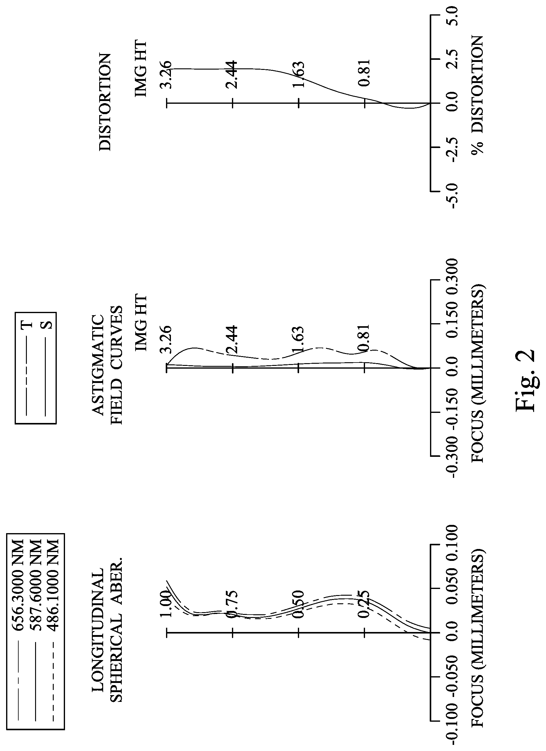
FIG. 2 shows spherical aberration curves, astigmatic field curves and a distortion curve of the image capturing apparatus according to the 1st embodiment;
FIG. 3 is a schematic view of an image capturing apparatus according to the 2nd embodiment of the present disclosure;
FIG. 4 shows spherical aberration curves, astigmatic field curves and a distortion curve of the image capturing apparatus according to the 2nd embodiment;
FIG. 5 is a schematic view of an image capturing apparatus according to the 3rd embodiment of the present disclosure;
FIG. 6 shows spherical aberration curves, astigmatic field curves and a distortion curve of the image capturing apparatus according to the 3rd embodiment;
FIG. 7 is a schematic view of an image capturing apparatus according to the 4th embodiment of the present disclosure;
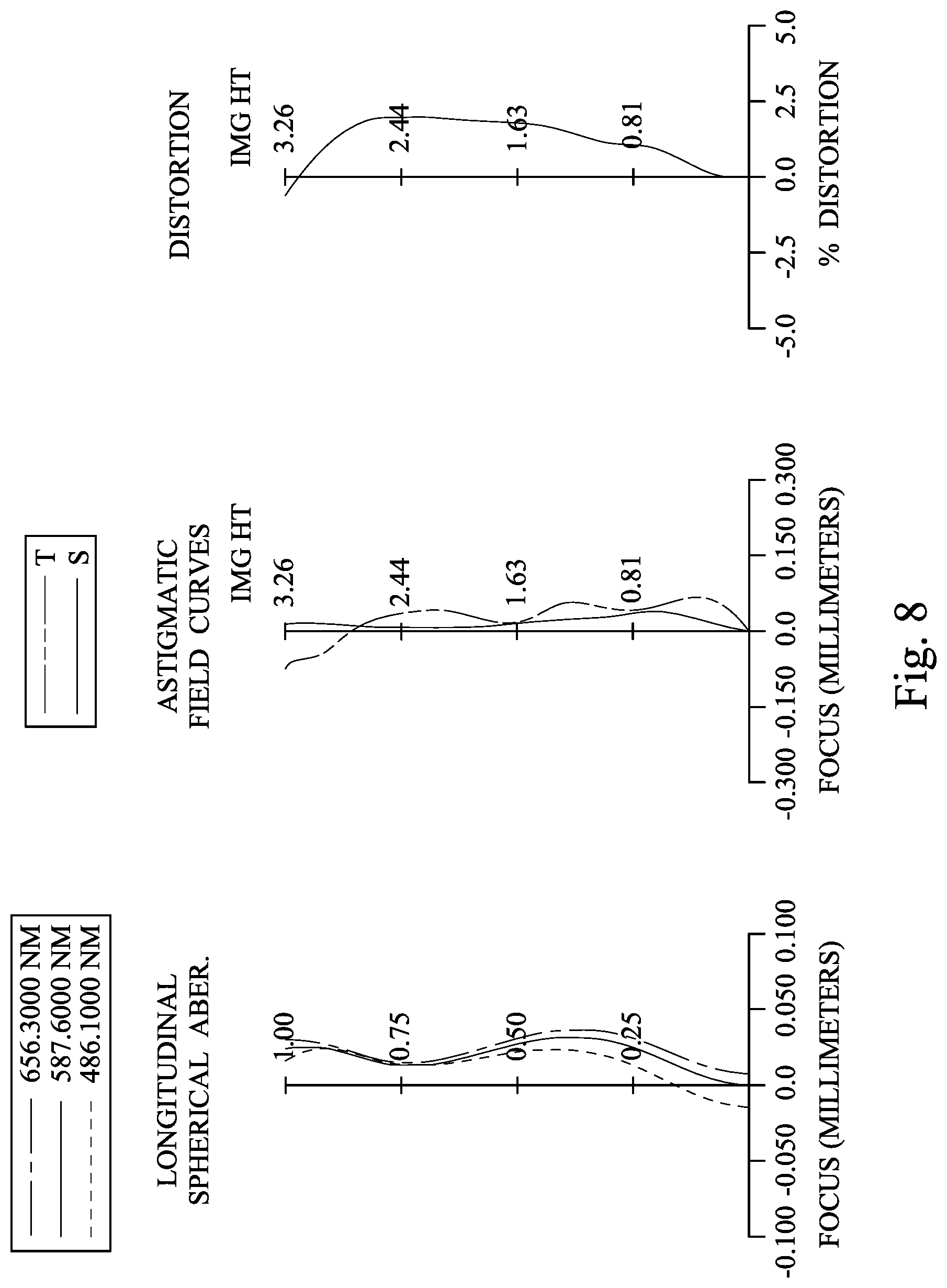
FIG. 8 shows spherical aberration curves, astigmatic field curves and a distortion curve of the image capturing apparatus according to the 4th embodiment;
FIG. 9 is a schematic view of an image capturing apparatus according to the 5th embodiment of the present disclosure;
FIG. 10 shows spherical aberration curves, astigmatic field curves and a distortion curve of the image capturing apparatus according to the 5th embodiment;
FIG. 11 is a schematic view of an image capturing apparatus according to the 6th embodiment of the present disclosure;
FIG. 12 shows spherical aberration curves, astigmatic field curves and a distortion curve of the image capturing apparatus according to the 6th embodiment;
FIG. 13 is a schematic view of an image capturing apparatus according to the 7th embodiment of the present disclosure;
FIG. 14 shows spherical aberration curves, astigmatic field curves and a distortion curve of the image capturing apparatus according to the 7th embodiment;
FIG. 15 is a schematic view of an image capturing apparatus according to the 8th embodiment of the present disclosure;
FIG. 16 shows spherical aberration curves, astigmatic field curves and a distortion curve of the image capturing apparatus according to the 8th embodiment;
FIG. 17 is a schematic view of a parameter SD62 according to the 1st embodiment of FIG. 1;
FIG. 18A is a system schematic view of an image capturing apparatus according to the 9th embodiment of the present disclosure;
FIG. 18B is a three dimensional schematic view of the image capturing apparatus of FIG. 18A;
FIG. 19A is a schematic view of one side of an electronic device according to the 10th embodiment of the present disclosure;
FIG. 19B is a schematic view of another side of the electronic device of FIG. 19A;
FIG. 20 is a schematic view of an electronic device according to the 11th embodiment of the present disclosure; and
FIG. 21 is a schematic view of an electronic device according to the 12th embodiment of the present disclosure.
DETAILED DESCRIPTION
A photographing optical lens system includes six lens elements, which are, in order from an object side to an image side, a first lens element, a second lens element, a third lens element, a fourth lens element, a fifth lens element and a sixth lens element.
The first lens element can have positive refractive power and can have an object-side surface being convex in a paraxial region thereof. Therefore, the sufficient light converging ability can be provided and the strength of the positive refractive power can be adjusted so as to reduce the total track length of the photographing optical lens system. Furthermore, the object-side surface of the first lens element can include at least one concave critical point in an off-axial region thereof. Therefore, it is favorable for the incident light from larger field of view traveling into the photographing optical lens system so as to obtain the arrangement of wide field of view.
The second lens element with positive refractive power has an image-side surface being convex in a paraxial region thereof. Therefore, the arrangement with the compact size and large field of view can be obtained.
The third lens element can have negative refractive power, and can have an object-side surface being convex in a paraxial region thereof, and has an image-side surface being concave in a paraxial region thereof. Therefore, aberrations generated from the first lens element and the second lens element can be corrected. Furthermore, the image-side surface of the third lens element can include at least one convex critical point in an off-axial region thereof. Therefore, it is favorable for the incident light from larger field of view traveling into the photographing optical lens system so as to obtain the arrangement of wide field of view.
The fourth lens element with negative refractive power has an object-side surface being concave in a paraxial region thereof. Therefore, the main negative refractive power of the photographing optical lens system can be positioned closer to the image surface, so that the photosensitivity can be reduced and astigmatism can be corrected.
The fifth lens element with positive refractive power can have an object-side surface being convex in a paraxial region thereof, and has an image-side surface being convex in a paraxial region thereof. Therefore, the arrangement of the positive refractive power of the photographing optical lens system can be balanced so as to enhance image quality.
The sixth lens element with negative refractive power has an image-side surface being concave in a paraxial region thereof. Therefore, the principal point can be positioned closer to the object side, so that the back focal length can be reduced for better controlling the total track length. Furthermore, the image-side surface of the sixth lens element includes at least one convex critical point in an off-axial region thereof, so that off-axial aberrations can be corrected for enhancing image quality on the peripheral region thereof.
When a focal length of the third lens element is f3, and a focal length of the fourth lens element is f4, the following condition is satisfied: -4.0<f4/|f3|. Therefore, the main negative refractive power can be positioned closer to the image surface by reducing the refractive power of the third lens element, so that the negative refractive power would not be positioned too close to the imaged object which may cause excessive sensitivity in the manufacturing tolerance of the third lens element and may limit its field of view due to the lens shape configuration of the third lens element. Preferably, the following condition can be satisfied: -1.5<f4/|f3|. More preferably, the following condition can be satisfied: -1.0<f4/|f3|. More preferably, the following condition can be satisfied: -0.80<f4/|f3|.
When an axial distance between the third lens element and the fourth lens element is T34, and an axial distance between the fifth lens element and the sixth lens element is T56, the following condition is satisfied: T56/T34<1.0. Therefore, it is favorable for avoiding assembling problems of thin lens elements such as the third lens element and the fourth lens element, being too close to each other, so that the manufacturability of the photographing optical lens system can be enhanced. Preferably, the following condition can be satisfied: T56/T34<0.40.
When a curvature radius of an object-side surface of the second lens element is R3, and a curvature radius of the image-side surface of the second lens element is R4, the following condition is satisfied: -0.70<(R3+R4)/(R3-R4). Therefore, the arrangement of the second lens element is favorable for the incident light from larger field of view traveling into the photographing optical lens system, and aberrations generated from the first lens element can be corrected to improve image quality. Preferably, the following condition can be satisfied: 0.50<(R3+R4)/(R3-R4)<4.0. More preferably, the following condition can be satisfied: 1.0.ltoreq.(R3+R4)/(R3-R4)<4.0.
When a focal length of the photographing optical lens system is f, a focal length of the fifth lens element is f5, and a focal length of the sixth lens element is f6, the following condition is satisfied: 3.75<(f/f5)+|f/f6|<7.5. Therefore, the main refractive power of the photographing optical lens system can be positioned toward the image surface so as to enable light converging favorably on the image surface.
When a focal length of the first lens element is f1, a focal length of the second lens element is f2, and the focal length of the fifth lens element is f5, the following condition is satisfied: 0.25<(f5/f1)+(f5/f2)<0.75. Therefore, the main positive refractive power of the photographing optical lens system can be positioned toward the image surface so as to provide the arrangement of large field of view and reduce the photosensitivity of the first lens element and the second lens element effectively.
When a sum of axial distances between every two of the lens elements of the photographing optical lens system that are adjacent to each other is .SIGMA.AT, and the axial distance between the third lens element and the fourth lens element is T34, the following condition is satisfied: 1.0<.SIGMA.AT/T34<2.0. Therefore, the compact arrangement among the lens elements can be ensured so as to utilize space effectively for miniaturization.
When a curvature radius of the object-side surface of the third lens element is R5, a curvature radius of the image-side surface of the third lens element is R6, and the focal length of the photographing optical lens system is f, the following condition is satisfied: 0.80<(R5+R6)/f<2.0. Therefore, it is favorable for reducing aberrations of the first lens element and the second lens element with the meniscus shape of the third lens element.
When an Abbe number of the third lens element is V3, an Abbe number of the fourth lens element is V4, and an Abbe number of the fifth lens element is V5, the following condition is satisfied: (V3+V4)/V5<1.0. Therefore, it is favorable for balancing corrections of chromatic aberration and astigmatism.
The photographing optical lens system can further include an aperture stop located between the first lens element and the third lens element. When an f-number of the photographing optical lens system is Fno, the following condition is satisfied: 1.20<Fno<2.45. Therefore, it is favorable for balancing the brightness of the image surface and the depth of field of the image so as to ensure sufficient illumination with high image clarity.
When the focal length of the first lens element is f1, the focal length of the second lens element is f2, the focal length of the third lens element is f3, the focal length of the fourth lens element is f4, the focal length of the fifth lens element is f5, the focal length of the sixth lens element is f6, and a focal length of the x-th lens element is fx, the following conditions are satisfied: |f5|<|fx|; and |f6|<|fx|, wherein x=1, 2, 3, 4. Therefore, the principal point can be positioned closer to the image surface so as to provide a large field of view.
When a curvature radius of the image-side surface of the third lens element is R6, a curvature radius of the object-side surface of the fourth lens element is R7, and the focal length of the photographing optical lens system is f, the following condition is satisfied: (|R6|+|R7|)/f<1.50. Therefore, the imaging ability can be enhanced by the aspheric characteristics of the third lens element and the fourth lens element.
When the focal length of the photographing optical lens system is f, and a curvature radius of the object-side surface of the sixth lens element is R11, the following condition is satisfied: f/R11<0.60. Therefore, the excessive variation of the surface shape of the sixth lens element can be avoided which would generate ghost images and surface reflections.
When the focal length of the photographing optical lens system is f, and a vertical distance between a maximum effective radius position on the image-side surface of the sixth lens element and an optical axis is SD62, the following condition is satisfied: 0.80<f/SD62<1.30. Therefore, the photographing optical lens system can provide the arrangements of large field of view and lens compactness.
Each of the aforementioned features of the photographing optical lens system can be utilized in numerous combinations, so as to achieve the corresponding effects.
According to the photographing optical lens system of the present disclosure, the lens elements thereof can be made of glass or plastic materials. When the lens elements are made of glass materials, the distribution of the refractive power of the photographing optical lens system may be more flexible to design. When the lens elements are made of plastic materials, manufacturing costs can be effectively reduced. Furthermore, surfaces of each lens element can be arranged to be aspheric, since the aspheric surface of the lens element is easy to form a shape other than a spherical surface so as to have more controllable variables for eliminating aberrations thereof, and to further decrease the required amount of lens elements in the photographing optical lens system. Therefore, the total track length of the photographing optical lens system can also be reduced.
According to the photographing optical lens system of the present disclosure, each of an object-side surface and an image-side surface has a paraxial region and an off-axial region. The paraxial region refers to the region of the surface where light rays travel close to an optical axis, and the off-axial region refers to the region of the surface away from the paraxial region. Particularly unless otherwise stated, when the lens element has a convex surface, it indicates that the surface can be convex in the paraxial region thereof; when the lens element has a concave surface, it indicates that the surface can be concave in the paraxial region thereof. According to the photographing optical lens system of the present disclosure, the refractive power or the focal length of a lens element being positive or negative may refer to the refractive power or the focal length in a paraxial region of the lens element.
According to the photographing optical lens system of the present disclosure, the photographing optical lens system can include at least one stop, such as an aperture stop, a glare stop or a field stop. Said glare stop or said field stop is for eliminating the stray light and thereby improving the image resolution thereof.
According to the photographing optical lens system of the present disclosure, the image surface of the photographing optical lens system, based on the corresponding image sensor, can be flat or curved. In particular, the image surface can be a concave curved surface facing towards the object side.
According to the photographing optical lens system of the present disclosure, an aperture stop can be configured as a front stop or a middle stop. A front stop disposed between an object and the first lens element can provide a longer distance between an exit pupil of the photographing optical lens system and the image surface, and thereby obtains a telecentric effect and improves the image-sensing efficiency of the image sensor, such as CCD or CMOS. A middle stop disposed between the first lens element and the image surface is favorable for enlarging the field of view of the photographing optical lens system and thereby provides a wider field of view for the same.
According to the photographing optical lens system of the present disclosure, a critical point is a non-axial point of the lens surface where its tangent is perpendicular to the optical axis, wherein a convex critical point is a critical point located on a convex shape of the lens surface, and the shape of the critical point (convex or concave) is determined by the positive or negative sign of the curvature at the critical point.
According to the photographing optical lens system of the present disclosure, the photographing optical lens system can be applied to 3D (three-dimensional) image capturing applications, in products such as digital cameras, mobile devices, digital tablets, smart TVs, surveillance systems, motion sensing input devices, driving recording systems, rearview camera systems, and wearable devices.
According to the present disclosure, an image capturing apparatus is provided. The image capturing apparatus includes the aforementioned photographing optical lens system and an image sensor, wherein the image sensor is disposed on the image side of the aforementioned photographing optical lens system, that is, the image sensor can be disposed on or near the image surface of the aforementioned photographing optical lens system. By arranging the second lens element with positive refractive power, the arrangement of lens compactness and large field of view can be obtained. By reducing the refractive power of the third lens element, it is favorable for avoiding the negative refractive power being positioned too close to the imaged object, which may cause overly sensitive manufacturing tolerance of the third lens element, and avoiding limited field of view due to a poor lens shape configuration. Preferably, the image capturing apparatus can further include a barrel member, a holder member or a combination thereof.
According to the present disclosure, an electronic device is provided, which includes the aforementioned image capturing apparatus. Preferably, the electronic device can further include but not limited to a control unit, a display, a storage unit, a random access memory unit (RAM) or a combination thereof.
According to the above description of the present disclosure, the following 1st-12th specific embodiments are provided for further explanation.
1st Embodiment
FIG. 1 is a schematic view of an image capturing apparatus according to the 1st embodiment of the present disclosure. FIG. 2 shows spherical aberration curves, astigmatic field curves and a distortion curve of the image capturing apparatus according to the 1st embodiment. In FIG. 1, the image capturing apparatus includes a photographing optical lens system (its reference numeral is omitted) and an image sensor 190. The photographing optical lens system includes, in order from an object side to an image side, a first lens element 110, an aperture stop 100, a second lens element 120, a stop 101, a third lens element 130, a fourth lens element 140, a fifth lens element 150, a sixth lens element 160, an IR-cut filter 170 and an image surface 180, wherein the image sensor 190 is disposed on the image surface 180 of the photographing optical lens system. The photographing optical lens system includes six lens elements (110, 120, 130, 140, 150, and 160) without additional one or more lens elements inserted between the first lens element 110 and the sixth lens element 160.
The first lens element 110 with positive refractive power has an object-side surface 111 being convex in a paraxial region thereof and an image-side surface 112 being concave in a paraxial region thereof. The first lens element 110 is made of a plastic material, and has the object-side surface 111 and the image-side surface 112 being both aspheric. Furthermore, the object-side surface 111 of the first lens element 110 includes at least one concave critical point in an off-axial region thereof.
The second lens element 120 with positive refractive power has an object-side surface 121 being concave in a paraxial region thereof and an image-side surface 122 being convex in a paraxial region thereof. The second lens element 120 is made of a plastic material, and has the object-side surface 121 and the image-side surface 122 being both aspheric.
The third lens element 130 with negative refractive power has an object-side surface 131 being convex in a paraxial region thereof and an image-side surface 132 being concave in a paraxial region thereof. The third lens element 130 is made of a plastic material, and has the object-side surface 131 and the image-side surface 132 being both aspheric. Furthermore, the image-side surface 132 of the third lens element 130 includes at least one convex critical point in an off-axial region thereof.
The fourth lens element 140 with negative refractive power has an object-side surface 141 being concave in a paraxial region thereof and an image-side surface 142 being convex in a paraxial region thereof. The fourth lens element 140 is made of a plastic material, and has the object-side surface 141 and the image-side surface 142 being both aspheric.
The fifth lens element 150 with positive refractive power has an object-side surface 151 being concave in a paraxial region thereof and an image-side surface 152 being convex in a paraxial region thereof. The fifth lens element 150 is made of a plastic material, and has the object-side surface 151 and the image-side surface 152 being both aspheric.
The sixth lens element 160 with negative refractive power has an object-side surface 161 being convex in a paraxial region thereof and an image-side surface 162 being concave in a paraxial region thereof. The sixth lens element 160 is made of a plastic material, and has the object-side surface 161 and the image-side surface 162 being both aspheric. Furthermore, the image-side surface 162 of the sixth lens element 160 includes at least one convex critical point in an off-axial region thereof.
The IR-cut filter 170 is made of a glass material and located between the sixth lens element 160 and the image surface 180, and will not affect the focal length of the photographing optical lens system.
The equation of the aspheric surface profiles of the aforementioned lens elements of the 1st embodiment is expressed as follows:
.function..function..times..times..times..times. ##EQU00001## where,
X is the relative distance between a point on the aspheric surface spaced at a distance Y from the optical axis and the tangential plane at the aspheric surface vertex on the optical axis;
Y is the vertical distance from the point on the aspheric surface to the optical axis;
R is the curvature radius;
k is the conic coefficient; and
Ai is the i-th aspheric coefficient.
In the photographing optical lens system according to the 1st embodiment, when a focal length of the photographing optical lens system is f, an f-number of the photographing optical lens system is Fno, and half of a maximum field of view of the photographing optical lens system is HFOV, these parameters have the following values: f=3.07 mm; Fno=1.95; and HFOV=46.0 degrees.
In the photographing optical lens system according to the 1st embodiment, when an Abbe number of the third lens element 130 is V3, an Abbe number of the fourth lens element 140 is V4, and an Abbe number of the fifth lens element 150 is V5, the following condition is satisfied: (V3+V4)/V5=0.88.
In the photographing optical lens system according to the 1st embodiment, when an axial distance between the first lens element 110 and the second lens element 120 is T12, an axial distance between the second lens element 120 and the third lens element 130 is T23, an axial distance between the third lens element 130 and the fourth lens element 140 is T34, an axial distance between the fourth lens element 140 and the fifth lens element 150 is T45, an axial distance between the fifth lens element 150 and the sixth lens element 160 is T56, and a sum of axial distances between every two of the lens elements of the photographing optical lens system that are adjacent to each other is .SIGMA.AT, (that is, .SIGMA.AT=T12+T23+T34+T45+T56), the following conditions are satisfied: T56/T34=0.06; and .SIGMA.AT/T34=1.50.
In the photographing optical lens system according to the 1st embodiment, when a curvature radius of the object-side surface 121 of the second lens element 120 is R3, and a curvature radius of the image-side surface 122 of the second lens element 120 is R4, the following condition is satisfied: (R3+R4)/(R3-R4)=1.63.
In the photographing optical lens system according to the 1st embodiment, when the focal length of the photographing optical lens system is f, a curvature radius of the object-side surface 131 of the third lens element 130 is R5, a curvature radius of the image-side surface 132 of the third lens element 130 is R6, and a curvature radius of the object-side surface 141 of the fourth lens element 140 is R7, the following conditions are satisfied: (R5+R6)/f=1.40; and (|R6|+|R7|)/f=1.03.
In the photographing optical lens system according to the 1st embodiment, when a focal length of the third lens element 130 is f3, and a focal length of the fourth lens element 140 is f4, the following condition is satisfied: f4/|f3|=-0.64.
In the photographing optical lens system according to the 1st embodiment, when a focal length of the first lens element 110 is f1, a focal length of the second lens element 120 is f2, a focal length of the fifth lens element 150 is f5, a focal length of the sixth lens element 160 is f6, the focal length of the photographing optical lens system is f, and the following conditions are satisfied: (f5/f1)+(f5/f2)=0.48; and (f/f5)+|f/f6|=4.55.
In the photographing optical lens system according to the 1st embodiment, when the focal length of the photographing optical lens system is f, and a curvature radius of the object-side surface 161 of the sixth lens element 160 is R11, the following condition is satisfied: f/R11=0.26.
FIG. 17 is a schematic view of a parameter SD62 according to the 1st embodiment of FIG. 1. In FIG. 17, when a vertical distance between a maximum effective radius position on the image-side surface 162 of the sixth lens element 160 and an optical axis is SD62, and the focal length of the photographing optical lens system is f, the following condition is satisfied: f/SD62=1.18.
The detailed optical data of the 1st embodiment are shown in Table 1 and the aspheric surface data are shown in Table 2 below.
TABLE-US-00001 TABLE 1 1st Embodiment f = 3.07 mm, Fno = 1.95, HFOV = 46.0 deg. Curvature Focal Surface # Radius Thickness Material Index Abbe # Length 0 Object Plano Infinity 1 Lens 1 3.246 ASP 0.275 Plastic 1.545 56.1 6.15 2 100.000 ASP -0.026 3 Ape. Stop Plano 0.180 4 Lens 2 -8.083 ASP 0.494 Plastic 1.534 55.9 4.65 5 -1.940 ASP -0.235 6 Stop Plano 0.265 7 Lens 3 2.634 ASP 0.240 Plastic 1.639 23.5 -7.64 8 1.650 ASP 0.487 9 Lens 4 -1.509 ASP 0.286 Plastic 1.614 26.0 -4.92 10 -3.235 ASP 0.030 11 Lens 5 -82.771 ASP 0.756 Plastic 1.544 56.0 1.27 12 -0.686 ASP 0.030 13 Lens 6 11.827 ASP 0.500 Plastic 1.544 56.0 -1.44 14 0.724 ASP 0.600 15 IR-cut filter Plano 0.100 Glass 1.517 64.2 -- 16 Plano 0.656 17 Image Plano -- Reference wavelength is 587.6 nm (d-line). Effective radius of Stop on Surface 6 is 0.900 mm.
TABLE-US-00002 TABLE 2 Aspheric Coefficients Surface # 1 2 4 5 7 8 k = 4.4546E+00 -9.0000E+01 7.3713E+01 4.2174E-01 -8.5907E+01 -1.4112E+01 A4 = -1.1948E-01 -1.1399E-01 5.0529E-02 -5.8051E-03 1.4945E-01 1.0784E-01 A6 = -1.6719E-01 -7.0465E-02 -9.2977E-02 -1.1390E-01 -1.3734E+00 -4.9897E-- 01 A8 = 3.0792E-01 -7.0072E-02 4.1590E-01 -8.6648E-02 3.1165E+00 8.6308E-01 A10 = -7.9723E-01 2.3293E-01 -1.8937E+00 8.5121E-01 -4.7471E+00 -9.8713E-01 A12 = 8.8593E-01 -1.6088E-01 4.0650E+00 -2.3342E+00 4.0731E+00 7.3034E-01 A14 = -3.0794E-01 9.6032E-02 -3.9842E+00 2.7021E+00 -1.5538E+00 -3.0982E-01 A16 = 1.3023E+00 -1.1989E+00 1.3436E-01 5.4519E-02 Surface # 9 10 11 12 13 14 k = -3.4420E+00 -7.1120E+01 -9.0000E+01 -3.1443E+00 -6.9630E+00 -5.5435E+0- 0 A4 = 1.5050E-01 -1.2599E-01 -1.8179E-01 -6.8708E-02 8.0343E-03 -4.2621E-02 A6 = -7.8198E-01 3.1902E-02 4.8169E-01 -5.5956E-02 -4.6193E-02 1.0830E-02 A8 = 1.6475E+00 4.4577E-02 -6.2340E-01 2.9046E-01 1.6616E-02 -3.3854E-03 A10 = -1.7224E+00 -2.5845E-01 4.7701E-01 -2.4627E-01 -1.1386E-03 8.4739E-04 A12 = 1.0512E+00 3.4276E-01 -2.1863E-01 9.3501E-02 -4.0754E-04 -1.3887E-04 A14 = -3.8522E-01 -1.8938E-01 5.3906E-02 -1.7163E-02 8.4328E-05 1.2630E-05 A16 = 6.7740E-02 4.0167E-02 -5.5184E-03 1.2347E-03 -4.8221E-06 -4.7645E-07
In Table 1, the curvature radius, the thickness and the focal length are shown in millimeters (mm). Surface numbers 0-17 represent the surfaces sequentially arranged from the object side to the image side along the optical axis. In Table 2, k represents the conic coefficient of the equation of the aspheric surface profiles. A4-A16 represent the aspheric coefficients ranging from the 4th order to the 16th order. The tables presented below for each embodiment correspond to schematic parameter and aberration curves of each embodiment, and term definitions of the tables are the same as those in Table 1 and Table 2 of the 1st embodiment. Therefore, an explanation in this regard will not be provided again.
Furthermore, in the photographing optical lens system according to the 1st embodiment, the focal length of the first lens element 110 is f1, the focal length of the second lens element 120 is f2, the focal length of the third lens element 130 is f3, the focal length of the fourth lens element 140 is f4, the focal length of the fifth lens element 150 is f5, the focal length of the sixth lens element 160 is f6, and a focal length of the x-th lens element is fx, the following conditions are satisfied: |f5|<|fx|; and |f6|<|fx|, wherein x=1, 2, 3, 4.
2nd Embodiment
FIG. 3 is a schematic view of an image capturing apparatus according to the 2nd embodiment of the present disclosure. FIG. 4 shows spherical aberration curves, astigmatic field curves and a distortion curve of the image capturing apparatus according to the 2nd embodiment. In FIG. 3, the image capturing apparatus includes a photographing optical lens system (its reference numeral is omitted) and an image sensor 290. The photographing optical lens system includes, in order from an object side to an image side, an aperture stop 200, a first lens element 210, a second lens element 220, a stop 201, a third lens element 230, a fourth lens element 240, a fifth lens element 250, a sixth lens element 260, an IR-cut filter 270 and an image surface 280, wherein the image sensor 290 is disposed on the image surface 280 of the photographing optical lens system. The photographing optical lens system includes six lens elements (210, 220, 230, 240, 250, and 260) without additional one or more lens elements inserted between the first lens element 210 and the sixth lens element 260.
The first lens element 210 with positive refractive power has an object-side surface 211 being convex in a paraxial region thereof and an image-side surface 212 being planar in a paraxial region thereof. The first lens element 210 is made of a plastic material, and has the object-side surface 211 and the image-side surface 212 being both aspheric. Furthermore, the object-side surface 211 of the first lens element 210 includes at least one concave critical point in an off-axial region thereof.
The second lens element 220 with positive refractive power has an object-side surface 221 being concave in a paraxial region thereof and an image-side surface 222 being convex in a paraxial region thereof. The second lens element 220 is made of a plastic material, and has the object-side surface 221 and the image-side surface 222 being both aspheric.
The third lens element 230 with negative refractive power has an object-side surface 231 being convex in a paraxial region thereof and an image-side surface 232 being concave in a paraxial region thereof. The third lens element 230 is made of a plastic material, and has the object-side surface 231 and the image-side surface 232 being both aspheric. Furthermore, the image-side surface 232 of the third lens element 230 includes at least one convex critical point in an off-axial region thereof.
The fourth lens element 240 with negative refractive power has an object-side surface 241 being concave in a paraxial region thereof and an image-side surface 242 being convex in a paraxial region thereof. The fourth lens element 240 is made of a plastic material, and has the object-side surface 241 and the image-side surface 242 being both aspheric.
The fifth lens element 250 with positive refractive power has an object-side surface 251 being convex in a paraxial region thereof and an image-side surface 252 being convex in a paraxial region thereof. The fifth lens element 250 is made of a plastic material, and has the object-side surface 251 and the image-side surface 252 being both aspheric.
The sixth lens element 260 with negative refractive power has an object-side surface 261 being concave in a paraxial region thereof and an image-side surface 262 being concave in a paraxial region thereof. The sixth lens element 260 is made of a plastic material, and has the object-side surface 261 and the image-side surface 262 being both aspheric. Furthermore, the image-side surface 262 of the sixth lens element 260 includes at least one convex critical point in an off-axial region thereof.
The IR-cut filter 270 is made of a glass material and located between the sixth lens element 260 and the image surface 280, and will not affect the focal length of the photographing optical lens system.
The detailed optical data of the 2nd embodiment are shown in Table 3 and the aspheric surface data are shown in Table 4 below.
TABLE-US-00003 TABLE 3 2nd Embodiment f = 2.88 mm, Fno = 2.03, HFOV = 48.5 deg. Focal Surface # Curvature Radius Thickness Material Index Abbe # Length 0 Object Plano Infinity 1 Ape. Stop Plano 0.018 2 Lens 1 3.748 ASP 0.292 Plastic 1.559 40.4 6.71 3 .infin. ASP 0.084 4 Lens 2 -5.742 ASP 0.548 Plastic 1.544 56.0 3.37 5 -1.436 ASP -0.118 6 Stop Plano 0.148 7 Lens 3 2.294 ASP 0.240 Plastic 1.660 20.4 -6.55 8 1.436 ASP 0.493 9 Lens 4 -1.112 ASP 0.281 Plastic 1.634 23.8 -3.29 10 -2.616 ASP 0.030 11 Lens 5 5.260 ASP 0.763 Plastic 1.559 40.4 1.13 12 -0.680 ASP 0.030 13 Lens 6 -100.000 ASP 0.440 Plastic 1.559 40.4 -1.31 14 0.739 ASP 0.600 15 IR-cut filter Plano 0.210 Glass 1.517 64.2 -- 16 Plano 0.474 17 Image Plano -- Reference wavelength is 587.6 nm (d-line). Effective radius of Stop on Surface 6 is 0.910 mm.
TABLE-US-00004 TABLE 4 Aspheric Coefficients Surface # 2 3 4 5 7 8 k = 1.9906E+01 0.0000E+00 1.4129E+01 -1.9719E-02 -4.8119E+01 -8.9165E+00 A4 = -2.0017E-01 -1.5246E-01 6.3364E-02 6.4676E-02 1.5915E-01 7.8868E-02 A6 = -2.3112E-01 -3.9093E-01 -4.9512E-01 -2.3206E-01 -1.4659E+00 -5.0750E-01 A8 = 7.3478E-02 3.6156E-01 1.0393E+00 3.1032E-02 3.2325E+00 9.2034E-01 A10 = -4.8673E-01 2.9763E-01 -2.0033E+00 9.3167E-01 -4.7837E+00 -1.0448E+00 A12 = 6.1186E-01 -6.3883E-01 3.8375E+00 -2.3542E+00 4.0793E+00 7.4129E-01 A14 = -3.1013E-01 7.2071E-01 -4.0867E+00 2.3405E+00 -1.5888E+00 -2.9072E-01 A16 = 1.6907E+00 -8.8840E-01 1.5620E-01 4.4192E-02 Surface # 9 10 11 12 13 14 k = -5.9467E+00 -9.0000E+01 -6.2709E+00 -3.3649E+00 9.0000E+01 -5.6993E+00- A4 = 1.8961E-01 -3.9291E-02 -2.1617E-01 -4.9540E-02 8.1588E-02 -4.7351E-0- 2 A6 = -9.4785E-01 -3.8080E-02 4.8859E-01 -4.5638E-02 -1.8933E-01 -3.0041E-03 A8 = 2.1338E+00 -1.2549E-01 -6.1926E-01 2.8295E-01 1.2491E-01 7.3871E-03 A10 = -2.4481E+00 1.5044E-01 4.7357E-01 -2.4684E-01 -4.4704E-02 -2.8235E-03 A12 = 1.5748E+00 -4.0637E-02 -2.1780E-01 9.3781E-02 9.4973E-03 5.2577E-04 A14 = -5.4859E-01 -1.7846E-02 5.3649E-02 -1.6988E-02 -1.1118E-03 -5.0156E-05 A16 = 8.1226E-02 1.0729E-02 -5.4416E-03 1.2002E-03 5.4654E-05 1.9479E-06
In the 2nd embodiment, the equation of the aspheric surface profiles of the aforementioned lens elements is the same as the equation of the 1st embodiment. Also, the definitions of these parameters shown in the following table are the same as those stated in the 1st embodiment with corresponding values for the 2nd embodiment, so an explanation in this regard will not be provided again.
Moreover, these parameters can be calculated from Table 3 and Table 4 as the following values and satisfy the following conditions:
TABLE-US-00005 2nd Embodiment f [mm] 2.88 (R5 + R6)/f 1.30 Fno 2.03 (|R6| + |R7|)/f 0.88 HFOV [deg.] 48.5 f4/|f3| -0.50 (V3 + V4)/V5 1.09 (f5/f1) + (f5/f2) 0.50 T56/T34 0.06 (f/f5) + |f/f6| 4.75 .SIGMA.AT/T34 1.35 f/R11 -0.03 (R3 + R4)/(R3 - R4) 1.67 f/SD62 1.14
Furthermore, in the photographing optical lens system according to the 2nd embodiment, the focal length of the first lens element 210 is f1, the focal length of the second lens element 220 is f2, the focal length of the third lens element 230 is f3, the focal length of the fourth lens element 240 is f4, the focal length of the fifth lens element 250 is f5, the focal length of the sixth lens element 260 is f6, and a focal length of the x-th lens element is fx, the following conditions are satisfied: |f5|<|fx|; and |f6|<|fx|, wherein x=1, 2, 3, 4.
3rd Embodiment
FIG. 5 is a schematic view of an image capturing apparatus according to the 3rd embodiment of the present disclosure. FIG. 6 shows spherical aberration curves, astigmatic field curves and a distortion curve of the image capturing apparatus according to the 3rd embodiment. In FIG. 5, the image capturing apparatus includes a photographing optical lens system (its reference numeral is omitted) and an image sensor 390. The photographing optical lens system includes, in order from an object side to an image side, a first lens element 310, an aperture stop 300, a second lens element 320, a stop 301, a third lens element 330, a fourth lens element 340, a fifth lens element 350, a sixth lens element 360, an IR-cut filter 370 and an image surface 380, wherein the image sensor 390 is disposed on the image surface 380 of the photographing optical lens system. The photographing optical lens system includes six lens elements (310, 320, 330, 340, 350, and 360) without additional one or more lens elements inserted between the first lens element 310 and the sixth lens element 360.
The first lens element 310 with positive refractive power has an object-side surface 311 being convex in a paraxial region thereof and an image-side surface 312 being concave in a paraxial region thereof. The first lens element 310 is made of a plastic material, and has the object-side surface 311 and the image-side surface 312 being both aspheric. Furthermore, the object-side surface 311 of the first lens element 310 includes at least one concave critical point in an off-axial region thereof.
The second lens element 320 with positive refractive power has an object-side surface 321 being concave in a paraxial region thereof and an image-side surface 322 being convex in a paraxial region thereof. The second lens element 320 is made of a plastic material, and has the object-side surface 321 and the image-side surface 322 being both aspheric.
The third lens element 330 with negative refractive power has an object-side surface 331 being convex in a paraxial region thereof and an image-side surface 332 being concave in a paraxial region thereof. The third lens element 330 is made of a plastic material, and has the object-side surface 331 and the image-side surface 332 being both aspheric. Furthermore, the image-side surface 332 of the third lens element 330 includes at least one convex critical point in an off-axial region thereof.
The fourth lens element 340 with negative refractive power has an object-side surface 341 being concave in a paraxial region thereof and an image-side surface 342 being concave in a paraxial region thereof. The fourth lens element 340 is made of a plastic material, and has the object-side surface 341 and the image-side surface 342 being both aspheric.
The fifth lens element 350 with positive refractive power has an object-side surface 351 being convex in a paraxial region thereof and an image-side surface 352 being convex in a paraxial region thereof. The fifth lens element 350 is made of a plastic material, and has the object-side surface 351 and the image-side surface 352 being both aspheric.
The sixth lens element 360 with negative refractive power has an object-side surface 361 being concave in a paraxial region thereof and an image-side surface 362 being concave in a paraxial region thereof. The sixth lens element 360 is made of a plastic material, and has the object-side surface 361 and the image-side surface 362 being both aspheric. Furthermore, the image-side surface 362 of the sixth lens element 360 includes at least one convex critical point in an off-axial region thereof.
The IR-cut filter 370 is made of a glass material and located between the sixth lens element 360 and the image surface 380, and will not affect the focal length of the photographing optical lens system.
The detailed optical data of the 3rd embodiment are shown in Table 5 and the aspheric surface data are shown in Table 6 below.
TABLE-US-00006 TABLE 5 3rd Embodiment f = 3.07 mm, Fno = 1.86, HFOV = 47.5 deg. Focal Surface # Curvature Radius Thickness Material Index Abbe # Length 0 Object Plano Infinity 1 Lens 1 2.784 ASP 0.312 Plastic 1.545 56.0 5.15 2 352.016 ASP -0.030 3 Ape. Stop Plano 0.223 4 Lens 2 -5.163 ASP 0.419 Plastic 1.544 55.9 9.74 5 -2.689 ASP -0.148 6 Stop Plano 0.198 7 Lens 3 2.447 ASP 0.255 Plastic 1.660 20.4 -13.00 8 1.825 ASP 0.269 9 Lens 4 -11.616 ASP 0.300 Plastic 1.639 23.5 -5.21 10 4.714 ASP 0.176 11 Lens 5 3.663 ASP 0.811 Plastic 1.544 55.9 1.27 12 -0.784 ASP 0.213 13 Lens 6 -2.884 ASP 0.350 Plastic 1.544 55.9 -1.32 14 0.993 ASP 0.650 15 IR-cut filter Plano 0.210 Glass 1.517 64.2 -- 16 Plano 0.295 17 Image Plano -- Reference wavelength is 587.6 nm (d-line). Effective radius of Stop on Surface 6 is 0.870 mm.
TABLE-US-00007 TABLE 6 Aspheric Coefficients Surface # 1 2 4 5 7 8 k = -5.0264E+00 9.0000E+01 -6.2009E+01 -1.2672E+00 -3.1743E+01 -7.5462E+00 A4 = -6.1488E-02 -9.2151E-02 -2.0263E-02 -2.3732E-01 -1.6154E-01 1.2278E-05 A6 = -5.3689E-02 -1.1544E-01 -4.5953E-03 3.4808E-01 -4.5578E-01 -3.9393E-01 A8 = -2.9959E-02 2.1625E-01 -6.1120E-02 -4.4297E-01 8.3500E-01 6.8269E-01 A10 = -8.9024E-02 -3.0893E-01 1.9716E-01 2.0668E-01 -7.2029E-01 -5.5349E-01 A12 = 1.0338E-01 2.1201E-01 -2.3824E-01 -6.8185E-02 2.3571E-02 1.9083E-01 A14 = 2.2626E-01 -2.2355E-02 Surface # 9 10 11 12 13 14 k = 1.8090E+01 2.9822E+00 -3.3705E+01 -3.2481E+00 -4.0116E+01 -7.2188E+00 A4 = -2.3670E-01 -6.0461E-01 -3.5299E-01 -7.0069E-02 -7.3717E-02 -3.9387E-- 02 A6 = 1.0470E+00 1.5550E+00 8.2541E-01 2.6502E-02 7.0775E-02 -1.7549E-03 A8 = -2.5281E+00 -2.8053E+00 -1.0145E+00 1.0619E-01 -1.2563E-01 2.8509E-03 A10 = 3.6182E+00 3.0323E+00 7.3820E-01 -9.7923E-02 8.6242E-02 -8.3115E-04 A12 = -2.9626E+00 -1.9799E+00 -3.2523E-01 3.6557E-02 -2.6884E-02 1.3031E-04 A14 = 1.2849E+00 7.2894E-01 7.8258E-02 -6.5095E-03 3.9936E-03 -1.1605E-05 A16 = -2.3079E-01 -1.1401E-01 -7.7332E-03 4.5521E-04 -2.3153E-04 4.5252E-07
In the 3rd embodiment, the equation of the aspheric surface profiles of the aforementioned lens elements is the same as the equation of the 1st embodiment. Also, the definitions of these parameters shown in the following table are the same as those stated in the 1st embodiment with corresponding values for the 3rd embodiment, so an explanation in this regard will not be provided again.
Moreover, these parameters can be calculated from Table 5 and Table 6 as the following values and satisfy the following conditions:
TABLE-US-00008 3rd Embodiment f [mm] 3.07 (R5 + R6)/f 1.39 Fno 1.86 (|R6| + |R7|)/f 4.38 HFOV [deg.] 47.5 f4/|f3| -0.40 (V3 + V4)/V5 0.79 (f5/f1) + (f5/f2) 0.38 T56/T34 0.79 (f/f5) + |f/f6| 4.74 .SIGMA.AT/T34 3.35 f/R11 -1.06 (R3 + R4)/(R3 - R4) 3.17 f/SD62 1.22
Furthermore, in the photographing optical lens system according to the 3rd embodiment, the focal length of the first lens element 310 is f1, the focal length of the second lens element 320 is f2, the focal length of the third lens element 330 is f3, the focal length of the fourth lens element 340 is f4, the focal length of the fifth lens element 350 is f5, the focal length of the sixth lens element 360 is f6, and a focal length of the x-th lens element is fx, the following conditions are satisfied: |f5|<|fx|; and |f6|<|fx|, wherein x=1, 2, 3, 4.
4th Embodiment
FIG. 7 is a schematic view of an image capturing apparatus according to the 4th embodiment of the present disclosure. FIG. 8 shows spherical aberration curves, astigmatic field curves and a distortion curve of the image capturing apparatus according to the 4th embodiment. In FIG. 7, the image capturing apparatus includes a photographing optical lens system (its reference numeral is omitted) and an image sensor 490. The photographing optical lens system includes, in order from an object side to an image side, a first lens element 410, an aperture stop 400, a second lens element 420, a stop 401, a third lens element 430, a fourth lens element 440, a fifth lens element 450, a sixth lens element 460, an IR-cut filter 470 and an image surface 480, wherein the image sensor 490 is disposed on the image surface 480 of the photographing optical lens system. The photographing optical lens system includes six lens elements (410, 420, 430, 440, 450, and 460) without additional one or more lens elements inserted between the first lens element 410 and the sixth lens element 460.
The first lens element 410 with positive refractive power has an object-side surface 411 being convex in a paraxial region thereof and an image-side surface 412 being convex in a paraxial region thereof. The first lens element 410 is made of a plastic material, and has the object-side surface 411 and the image-side surface 412 being both aspheric. Furthermore, the object-side surface 411 of the first lens element 410 includes at least one concave critical point in an off-axial region thereof.
The second lens element 420 with positive refractive power has an object-side surface 421 being concave in a paraxial region thereof and an image-side surface 422 being convex in a paraxial region thereof. The second lens element 420 is made of a plastic material, and has the object-side surface 421 and the image-side surface 422 being both aspheric.
The third lens element 430 with negative refractive power has an object-side surface 431 being convex in a paraxial region thereof and an image-side surface 432 being concave in a paraxial region thereof. The third lens element 430 is made of a plastic material, and has the object-side surface 431 and the image-side surface 432 being both aspheric. Furthermore, the image-side surface 432 of the third lens element 430 includes at least one convex critical point in an off-axial region thereof.
The fourth lens element 440 with negative refractive power has an object-side surface 441 being concave in a paraxial region thereof and an image-side surface 442 being convex in a paraxial region thereof. The fourth lens element 440 is made of a plastic material, and has the object-side surface 441 and the image-side surface 442 being both aspheric.
The fifth lens element 450 with positive refractive power has an object-side surface 451 being convex in a paraxial region thereof and an image-side surface 452 being convex in a paraxial region thereof. The fifth lens element 450 is made of a plastic material, and has the object-side surface 451 and the image-side surface 452 being both aspheric.
The sixth lens element 460 with negative refractive power has an object-side surface 461 being convex in a paraxial region thereof and an image-side surface 462 being concave in a paraxial region thereof. The sixth lens element 460 is made of a plastic material, and has the object-side surface 461 and the image-side surface 462 being both aspheric. Furthermore, the image-side surface 462 of the sixth lens element 460 includes at least one convex critical point in an off-axial region thereof.
The IR-cut filter 470 is made of a glass material and located between the sixth lens element 460 and the image surface 480, and will not affect the focal length of the photographing optical lens system.
The detailed optical data of the 4th embodiment are shown in Table 7 and the aspheric surface data are shown in Table 8 below.
TABLE-US-00009 TABLE 7 4th Embodiment f = 2.74 mm, Fno = 1.86, HFOV = 50.0 deg. Focal Surface # Curvature Radius Thickness Material Index Abbe # Length 0 Object Plano Infinity 1 Lens 1 5.272 ASP 0.273 Plastic 1.545 56.0 5.95 2 -8.271 ASP -0.065 3 Ape. Stop Plano 0.185 4 Lens 2 -3.926 ASP 0.497 Plastic 1.544 55.9 5.73 5 -1.814 ASP -0.234 6 Stop Plano 0.264 7 Lens 3 1.686 ASP 0.240 Plastic 1.660 20.4 -22.09 8 1.426 ASP 0.472 9 Lens 4 -1.107 ASP 0.281 Plastic 1.639 23.5 -3.93 10 -2.176 ASP 0.030 11 Lens 5 11.003 ASP 0.756 Plastic 1.544 55.9 1.10 12 -0.616 ASP 0.030 13 Lens 6 5.635 ASP 0.352 Plastic 1.544 55.9 -1.27 14 0.600 ASP 0.800 15 IR-cut filter Plano 0.210 Glass 1.517 64.2 -- 16 Plano 0.313 17 Image Plano -- Reference wavelength is 587.6 nm (d-line). Effective radius of Stop on Surface 6 is 0.900 mm.
TABLE-US-00010 TABLE 8 Aspheric Coefficients Surface # 1 2 4 5 7 8 k = 1.3035E+01 1.2036E+01 -1.5203E+00 1.1437E+00 -2.0327E+01 -3.9507E+00 A4 = -1.6299E-01 -9.0345E-02 1.7314E-01 -2.2677E-02 2.0222E-01 1.2662E-02 A6 = -1.8868E-01 -2.3245E-01 -5.1565E-01 -1.5330E-01 -1.5626E+00 -5.0898E-- 01 A8 = 2.6922E-01 1.0117E-01 9.4592E-01 2.8626E-02 3.2310E+00 9.4591E-01 A10 = -7.2246E-01 1.8073E-01 -2.3226E+00 7.6622E-01 -4.7485E+00 -1.0321E+00 A12 = 8.8593E-01 -1.6088E-01 4.0650E+00 -2.3342E+00 4.0731E+00 7.3033E-01 A14 = -3.0794E-01 9.6032E-02 -3.9842E+00 2.7021E+00 -1.5538E+00 -3.0980E-01 A16 = 1.3023E+00 -1.1989E+00 1.3436E-01 5.4519E-02 Surface # 9 10 11 12 13 14 k = -5.8370E+00 -6.7441E+01 1.3509E+01 -3.6971E+00 -6.9630E+00 -5.3743E+00 A4 = 4.8853E-02 -2.8019E-01 -2.1861E-01 -1.0833E-01 -3.9857E-02 -5.6991E-- 02 A6 = -5.1060E-01 7.0754E-01 4.9920E-01 -8.1761E-03 -3.4151E-02 1.1169E-02 A8 = 1.1856E+00 -1.5437E+00 -6.1811E-01 2.8129E-01 2.2000E-02 -8.7704E-04 A10 = -9.2961E-01 1.8989E+00 4.7291E-01 -2.4877E-01 -6.5279E-03 -4.5389E-04 A12 = 2.0304E-01 -1.3575E+00 -2.1782E-01 9.3772E-02 1.3288E-03 1.7650E-04 A14 = 7.6361E-02 5.4144E-01 5.3899E-02 -1.6931E-02 -1.6635E-04 -2.6313E-05 A16 = -3.1804E-02 -9.0199E-02 -5.5165E-03 1.2022E-03 8.8899E-06 1.4313E-06
In the 4th embodiment, the equation of the aspheric surface profiles of the aforementioned lens elements is the same as the equation of the 1st embodiment. Also, the definitions of these parameters shown in the following table are the same as those stated in the 1st embodiment with corresponding values for the 4th embodiment, so an explanation in this regard will not be provided again.
Moreover, these parameters can be calculated from Table 7 and Table 8 as the following values and satisfy the following conditions:
TABLE-US-00011 4th Embodiment f [mm] 2.74 (R5 + R6)/f 1.14 Fno 1.86 (|R6| + |R7|)/f 0.92 HFOV [deg.] 50.0 f4/|f3| -0.18 (V3 + V4)/V5 0.79 (f5/f1) + (f5/f2) 0.38 T56/T34 0.06 (f/f5) + |f/f6| 4.65 .SIGMA.AT/T34 1.44 f/R11 0.49 (R3 + R4)/(R3 - R4) 2.72 f/SD62 1.09
Furthermore, in the photographing optical lens system according to the 4th embodiment, the focal length of the first lens element 410 is f1, the focal length of the second lens element 420 is f2, the focal length of the third lens element 430 is f3, the focal length of the fourth lens element 440 is f4, the focal length of the fifth lens element 450 is f5, the focal length of the sixth lens element 460 is f6, and a focal length of the x-th lens element is fx, the following conditions are satisfied: |f5|<|fx|; and |f6|<|fx|, wherein x=1, 2, 3, 4.
5th Embodiment
FIG. 9 is a schematic view of an image capturing apparatus according to the 5th embodiment of the present disclosure. FIG. 10 shows spherical aberration curves, astigmatic field curves and a distortion curve of the image capturing apparatus according to the 5th embodiment. In FIG. 9, the image capturing apparatus includes a photographing optical lens system (its reference numeral is omitted) and an image sensor 590. The photographing optical lens system includes, in order from an object side to an image side, a first lens element 510, an aperture stop 500, a second lens element 520, a third lens element 530, a fourth lens element 540, a fifth lens element 550, a sixth lens element 560, an IR-cut filter 570 and an image surface 580, wherein the image sensor 590 is disposed on the image surface 580 of the photographing optical lens system. The photographing optical lens system includes six lens elements (510, 520, 530, 540, 550, and 560) without additional one or more lens elements inserted between the first lens element 510 and the sixth lens element 560.
The first lens element 510 with positive refractive power has an object-side surface 511 being convex in a paraxial region thereof and an image-side surface 512 being convex in a paraxial region thereof. The first lens element 510 is made of a plastic material, and has the object-side surface 511 and the image-side surface 512 being both aspheric. Furthermore, the object-side surface 511 of the first lens element 510 includes at least one concave critical point in an off-axial region thereof.
The second lens element 520 with positive refractive power has an object-side surface 521 being concave in a paraxial region thereof and an image-side surface 522 being convex in a paraxial region thereof. The second lens element 520 is made of a plastic material, and has the object-side surface 521 and the image-side surface 522 being both aspheric.
The third lens element 530 with positive refractive power has an object-side surface 531 being convex in a paraxial region thereof and an image-side surface 532 being concave in a paraxial region thereof. The third lens element 530 is made of a plastic material, and has the object-side surface 531 and the image-side surface 532 being both aspheric. Furthermore, the image-side surface 532 of the third lens element 530 includes at least one convex critical point in an off-axial region thereof.
The fourth lens element 540 with negative refractive power has an object-side surface 541 being concave in a paraxial region thereof and an image-side surface 542 being convex in a paraxial region thereof. The fourth lens element 540 is made of a plastic material, and has the object-side surface 541 and the image-side surface 542 being both aspheric.
The fifth lens element 550 with positive refractive power has an object-side surface 551 being convex in a paraxial region thereof and an image-side surface 552 being convex in a paraxial region thereof. The fifth lens element 550 is made of a plastic material, and has the object-side surface 551 and the image-side surface 552 being both aspheric.
The sixth lens element 560 with negative refractive power has an object-side surface 561 being convex in a paraxial region thereof and an image-side surface 562 being concave in a paraxial region thereof. The sixth lens element 560 is made of a plastic material, and has the object-side surface 561 and the image-side surface 562 being both aspheric. Furthermore, the image-side surface 562 of the sixth lens element 560 includes at least one convex critical point in an off-axial region thereof.
The IR-cut filter 570 is made of a glass material and located between the sixth lens element 560 and the image surface 580, and will not affect the focal length of the photographing optical lens system.
The detailed optical data of the 5th embodiment are shown in Table 9 and the aspheric surface data are shown in Table 10 below.
TABLE-US-00012 TABLE 9 5th Embodiment f = 2.87 mm, Fno = 2.12, HFOV= 48.5 deg. Focal Surface # Curvature Radius Thickness Material Index Abbe # Length 0 Object Plano Infinity 1 Lens 1 4.265 ASP 0.279 Plastic 1.545 56.1 4.58 2 -5.892 ASP -0.031 3 Ape. Stop Plano 0.131 4 Lens 2 -3.035 ASP 0.475 Plastic 1.534 55.9 12.83 5 -2.217 ASP 0.087 6 Lens 3 2.023 ASP 0.240 Plastic 1.660 20.4 288.98 7 1.948 ASP 0.436 8 Lens 4 -1.133 ASP 0.280 Plastic 1.639 23.5 -3.85 9 -2.302 ASP 0.030 10 Lens 5 29.502 ASP 0.803 Plastic 1.544 56.0 1.17 11 -0.644 ASP 0.030 12 Lens 6 5.898 ASP 0.416 Plastic 1.544 56.0 -1.35 13 0.638 ASP 0.800 14 IR-cut filter Plano 0.210 Glass 1.517 64.2 -- 15 Plano 0.367 16 Image Plano -- Reference wavelength is 587.6 nm (d-line).
TABLE-US-00013 TABLE 10 Aspheric Coefficients Surface # 1 2 4 5 6 7 k = 1.0120E+01 -1.3224E+01 4.0432E+00 2.8343E+00 -3.5693E+01 -2.7423E+00 A4 = -1.3549E-01 -9.3553E-02 1.4308E-01 -1.1791E-01 1.9245E-01 9.0772E-03 A6 = -2.0888E-01 -1.5356E-01 -3.7120E-01 -5.9273E-02 -1.5582E+00 -5.1552E-01 A8 = 2.7495E-01 1.3343E-01 1.0242E+00 3.8538E-03 3.2334E+00 9.5003E-01 A10 = -6.9544E-01 1.2684E-01 -2.5298E+00 7.5575E-01 -4.7826E+00 -1.0290E+00 A12 = 9.3635E-01 -2.7702E-01 4.0324E+00 -2.3680E+00 4.0604E+00 7.3192E-01 A14 = -3.7269E-01 2.4875E-01 -4.1285E+00 2.6984E+00 -1.5523E+00 -3.1044E-01 A16 = 1.5389E+00 -1.2055E+00 1.7002E-01 5.4741E-02 Surface # 8 9 10 11 12 13 k = -5.3274E+00 -6.2280E+01 9.0000E+01 -3.4807E+00 -6.9627E+00 -5.3122E+00- A4 = 3.5841E-02 -2.5920E-01 -1.7819E-01 -1.2153E-01 -5.9481E-02 -4.5386E-02 A6 = -5.1164E-01 7.0873E-01 4.9242E-01 -1.4654E-03 4.1086E-02 1.4551E-02 A8 = 1.1875E+00 -1.5487E+00 -6.2226E-01 2.8307E-01 -4.6140E-02 -5.8218E-03 A10 = -9.2783E-01 1.8943E+00 4.7364E-01 -2.4938E-01 2.1967E-02 1.4837E-03 A12 = 2.0612E-01 -1.3584E+00 -2.1704E-01 9.3518E-02 -4.8921E-03 -2.1697E-04 A14 = 7.6780E-02 5.4158E-01 5.4113E-02 -1.6877E-02 5.2188E-04 1.6256E-05 A16 = -3.4204E-02 -9.0173E-02 -5.6893E-03 1.2050E-03 -2.1617E-05 -4.7676E-07
In the 5th embodiment, the equation of the aspheric surface profiles of the aforementioned lens elements is the same as the equation of the 1st embodiment. Also, the definitions of these parameters shown in the following table are the same as those stated in the 1st embodiment with corresponding values for the 5th embodiment, so an explanation in this regard will not be provided again.
Moreover, these parameters can be calculated from Table 9 and Table 10 as the following values and satisfy the following conditions:
TABLE-US-00014 5th Embodiment f [mm] 2.87 (R5 + R6)/f 1.38 Fno 2.12 (|R6| + |R7|)/f 1.07 HFOV [deg.] 48.5 f4/|f3| -0.01 (V3 + V4)/V5 0.78 (f5/f1) + (f5/f2) 0.35 T56/T34 0.07 (f/f5) + |f/f6| 4.58 .SIGMA.AT/T34 1.57 f/R11 0.49 (R3 + R4)/(R3 - R4) 6.43 f/SD62 1.12
Furthermore, in the photographing optical lens system according to the 5th embodiment, the focal length of the first lens element 510 is f1, the focal length of the second lens element 520 is f2, the focal length of the third lens element 530 is f3, the focal length of the fourth lens element 540 is f4, the focal length of the fifth lens element 550 is f5, the focal length of the sixth lens element 560 is f6, and a focal length of the x-th lens element is fx, the following conditions are satisfied: |f5|<|fx|; and |f6|<|fx|, wherein x=1, 2, 3, 4.
6th Embodiment
FIG. 11 is a schematic view of an image capturing apparatus according to the 6th embodiment of the present disclosure. FIG. 12 shows spherical aberration curves, astigmatic field curves and a distortion curve of the image capturing apparatus according to the 6th embodiment. In FIG. 11, the image capturing apparatus includes a photographing optical lens system (its reference numeral is omitted) and an image sensor 690. The photographing optical lens system includes, in order from an object side to an image side, an aperture stop 600, a first lens element 610, a second lens element 620, a third lens element 630, a fourth lens element 640, a fifth lens element 650, a sixth lens element 660, an IR-cut filter 670 and an image surface 680, wherein the image sensor 690 is disposed on the image surface 680 of the photographing optical lens system. The photographing optical lens system includes six lens elements (610, 620, 630, 640, 650, and 660) without additional one or more lens elements inserted between the first lens element 610 and the sixth lens element 660.
The first lens element 610 with positive refractive power has an object-side surface 611 being convex in a paraxial region thereof and an image-side surface 612 being concave in a paraxial region thereof. The first lens element 610 is made of a plastic material, and has the object-side surface 611 and the image-side surface 612 being both aspheric.
The second lens element 620 with positive refractive power has an object-side surface 621 being concave in a paraxial region thereof and an image-side surface 622 being convex in a paraxial region thereof. The second lens element 620 is made of a plastic material, and has the object-side surface 621 and the image-side surface 622 being both aspheric.
The third lens element 630 with negative refractive power has an object-side surface 631 being convex in a paraxial region thereof and an image-side surface 632 being concave in a paraxial region thereof. The third lens element 630 is made of a plastic material, and has the object-side surface 631 and the image-side surface 632 being both aspheric. Furthermore, the image-side surface 632 of the third lens element 630 includes at least one convex critical point in an off-axial region thereof.
The fourth lens element 640 with negative refractive power has an object-side surface 641 being concave in a paraxial region thereof and an image-side surface 642 being convex in a paraxial region thereof. The fourth lens element 640 is made of a plastic material, and has the object-side surface 641 and the image-side surface 642 being both aspheric.
The fifth lens element 650 with positive refractive power has an object-side surface 651 being convex in a paraxial region thereof and an image-side surface 652 being convex in a paraxial region thereof. The fifth lens element 650 is made of a plastic material, and has the object-side surface 651 and the image-side surface 652 being both aspheric.
The sixth lens element 660 with negative refractive power has an object-side surface 661 being convex in a paraxial region thereof and an image-side surface 662 being concave in a paraxial region thereof. The sixth lens element 660 is made of a plastic material, and has the object-side surface 661 and the image-side surface 662 being both aspheric. Furthermore, the image-side surface 662 of the sixth lens element 660 includes at least one convex critical point in an off-axial region thereof.
The IR-cut filter 670 is made of a glass material and located between the sixth lens element 660 and the image surface 680, and will not affect the focal length of the photographing optical lens system.
The detailed optical data of the 6th embodiment are shown in Table 11 and the aspheric surface data are shown in Table 12 below.
TABLE-US-00015 TABLE 11 6th Embodiment f = 2.74 mm, Fno = 2.25, HFOV = 50.0 deg. Focal Surface # Curvature Radius Thickness Material Index Abbe # Length 0 Object Plano Infinity 1 Ape. Stop Plano -0.048 2 Lens 1 2.326 ASP 0.324 Plastic 1.559 40.4 6.41 3 6.312 ASP 0.100 4 Lens 2 -6.095 ASP 0.436 Plastic 1.544 56.0 3.98 5 -1.639 ASP 0.030 6 Lens 3 2.993 ASP 0.240 Plastic 1.671 19.5 -6.93 7 1.762 ASP 0.357 8 Lens 4 -1.385 ASP 0.398 Plastic 1.584 28.2 -2.69 9 -12.806 ASP 0.030 10 Lens 5 2.262 ASP 0.890 Plastic 1.544 56.0 0.98 11 -0.599 ASP 0.030 12 Lens 6 14.370 ASP 0.350 Plastic 1.559 40.4 -1.14 13 0.604 ASP 0.800 14 IR-cut filter Plano 0.210 Glass 1.517 64.2 -- 15 Plano 0.289 16 Image Plano -- Reference wavelength is 587.6 nm (d-line).
TABLE-US-00016 TABLE 12 Aspheric Coefficients Surface # 2 3 4 5 6 7 k = 9.2769E+00 -1.1474E+00 -2.0960E+01 -1.5429E+00 -7.6610E+01 -1.3904E+0- 1 A4 = -1.4584E-01 -8.5980E-02 1.2983E-01 7.4582E-02 5.5174E-02 4.7413E-02 A6 = -5.2796E-01 -3.2092E-01 -3.6262E-01 -1.9666E-01 -1.3726E+00 -4.8618E-- 01 A8 = 6.4427E-01 -6.9457E-01 4.5894E-01 1.0092E-01 3.1317E+00 9.2749E-01 A10 = -9.6969E-01 4.6210E-01 -2.8415E+00 9.3734E-01 -4.8551E+00 -1.0499E+00 A12 = -2.0668E+00 4.1750E-01 4.8672E+00 -2.3539E+00 4.0521E+00 7.3512E-01 A14 = 1.1443E+00 1.0412E-01 1.7959E-01 2.2692E+00 -1.6015E+00 -2.9942E-01 A16 = -3.0418E+00 -9.9686E-01 1.4578E-01 5.2467E-02 Surface # 8 9 10 11 12 13 k = -5.6464E+00 8.3777E+01 -8.9995E+01 -3.6289E+00 -6.8727E+00 -5.2264E+00 A4 = 1.1826E-01 -2.6741E-01 -9.7092E-02 -1.4285E-01 -1.1134E-01 -8.3325E-- 02 A6 = -5.5031E-01 7.0317E-01 1.8932E-01 2.9742E-02 4.0244E-02 2.7389E-02 A8 = 1.1563E+00 -1.5574E+00 -1.8677E-01 1.8762E-01 -2.5450E-02 -5.6426E-03 A10 = -9.2846E-01 1.8890E+00 1.0657E-01 -1.5501E-01 1.4200E-02 4.8561E-04 A12 = 2.1688E-01 -1.3597E+00 -3.4047E-02 5.2001E-02 -4.1124E-03 3.2930E-05 A14 = 8.1177E-02 5.4207E-01 4.8237E-03 -8.2142E-03 5.9152E-04 -1.0566E-05 A16 = -3.6558E-02 -8.8641E-02 -1.5094E-04 5.0452E-04 -3.4169E-05 6.2438E-07
In the 6th embodiment, the equation of the aspheric surface profiles of the aforementioned lens elements is the same as the equation of the 1st embodiment. Also, the definitions of these parameters shown in the following table are the same as those stated in the 1st embodiment with corresponding values for the 6th embodiment, so an explanation in this regard will not be provided again.
Moreover, these parameters can be calculated from Table 11 and Table 12 as the following values and satisfy the following conditions:
TABLE-US-00017 6th Embodiment f [mm] 2.74 (R5 + R6)/f 1.74 Fno 2.25 (|R6| + |R7|)/f 1.15 HFOV [deg.] 50.0 f4/|f3| -0.39 (V3 + V4)/V5 0.85 (f5/f1) + (f5/f2) 0.40 T56/T34 0.08 (f/f5) + |f/f6| 5.20 .SIGMA.AT/T34 1.53 f/R11 0.19 (R3 + R4)/(R3 - R4) 1.74 f/SD62 1.07
Furthermore, in the photographing optical lens system according to the 6th embodiment, when the focal length of the first lens element 610 is f1, the focal length of the second lens element 620 is f2, the focal length of the third lens element 630 is f3, the focal length of the fourth lens element 640 is f4, the focal length of the fifth lens element 650 is f5, the focal length of the sixth lens element 660 is f6, and a focal length of the x-th lens element is fx, the following conditions are satisfied: |f5|<|fx|; and |f6|<|fx|, wherein x=1, 2, 3, 4.
7th Embodiment
FIG. 13 is a schematic view of an image capturing apparatus according to the 7th embodiment of the present disclosure. FIG. 14 shows spherical aberration curves, astigmatic field curves and a distortion curve of the image capturing apparatus according to the 7th embodiment. In FIG. 13, the image capturing apparatus includes a photographing optical lens system (its reference numeral is omitted) and an image sensor 790. The photographing optical lens system includes, in order from an object side to an image side, an aperture stop 700, a first lens element 710, a second lens element 720, a third lens element 730, a fourth lens element 740, a fifth lens element 750, a sixth lens element 760, an IR-cut filter 770 and an image surface 780, wherein the image sensor 790 is disposed on the image surface 780 of the photographing optical lens system. The photographing optical lens system includes six lens elements (710, 720, 730, 740, 750, and 760) without additional one or more lens elements inserted between the first lens element 710 and the sixth lens element 760.
The first lens element 710 with positive refractive power has an object-side surface 711 being convex in a paraxial region thereof and an image-side surface 712 being concave in a paraxial region thereof. The first lens element 710 is made of a plastic material, and has the object-side surface 711 and the image-side surface 712 being both aspheric.
The second lens element 720 with positive refractive power has an object-side surface 721 being convex in a paraxial region thereof and an image-side surface 722 being convex in a paraxial region thereof. The second lens element 720 is made of a plastic material, and has the object-side surface 721 and the image-side surface 722 being both aspheric.
The third lens element 730 with negative refractive power has an object-side surface 731 being convex in a paraxial region thereof and an image-side surface 732 being concave in a paraxial region thereof. The third lens element 730 is made of a plastic material, and has the object-side surface 731 and the image-side surface 732 being both aspheric. Furthermore, the image-side surface 732 of the third lens element 730 includes at least one convex critical point in an off-axial region thereof.
The fourth lens element 740 with negative refractive power has an object-side surface 741 being concave in a paraxial region thereof and an image-side surface 742 being concave in a paraxial region thereof. The fourth lens element 740 is made of a plastic material, and has the object-side surface 741 and the image-side surface 742 being both aspheric.
The fifth lens element 750 with positive refractive power has an object-side surface 751 being convex in a paraxial region thereof and an image-side surface 752 being convex in a paraxial region thereof. The fifth lens element 750 is made of a plastic material, and has the object-side surface 751 and the image-side surface 752 being both aspheric.
The sixth lens element 760 with negative refractive power has an object-side surface 761 being convex in a paraxial region thereof and an image-side surface 762 being concave in a paraxial region thereof. The sixth lens element 760 is made of a plastic material, and has the object-side surface 761 and the image-side surface 762 being both aspheric. Furthermore, the image-side surface 762 of the sixth lens element 760 includes at least one convex critical point in an off-axial region thereof.
The IR-cut filter 770 is made of a glass material and located between the sixth lens element 760 and the image surface 780, and will not affect the focal length of the photographing optical lens system.
The detailed optical data of the 7th embodiment are shown in Table 13 and the aspheric surface data are shown in Table 14 below.
TABLE-US-00018 TABLE 13 7th Embodiment f = 3.04 mm, Fno = 2.25, HFOV = 46.1 deg. Focal Surface # Curvature Radius Thickness Material Index Abbe # Length 0 Object Plano Infinity 1 Ape. Stop Plano -0.061 2 Lens 1 2.278 ASP 0.344 Plastic 1.545 56.1 7.10 3 5.245 ASP 0.100 4 Lens 2 101.904 ASP 0.544 Plastic 1.545 56.1 3.81 5 -2.115 ASP 0.030 6 Lens 3 3.211 ASP 0.240 Plastic 1.614 25.6 -6.73 7 1.756 ASP 0.364 8 Lens 4 -1.639 ASP 0.280 Plastic 1.584 28.2 -2.61 9 22.828 ASP 0.052 10 Lens 5 2.370 ASP 0.927 Plastic 1.545 56.1 0.99 11 -0.605 ASP 0.034 12 Lens 6 13.828 ASP 0.356 Plastic 1.545 56.1 -1.11 13 0.574 ASP 0.800 14 IR-cut filter Plano 0.210 Glass 1.517 64.2 -- 15 Plano 0.328 16 Image Plano -- Reference wavelength is 587.6 nm (d-line).
TABLE-US-00019 TABLE 14 Aspheric Coefficients Surface # 2 3 4 5 6 7 k = 7.2241E+00 2.0999E+01 9.0000E+01 -1.2504E+00 -9.0000E+01 -9.4138E+00 A4 = -1.1706E-01 -2.4989E-02 1.4018E-01 6.4091E-02 8.8693E-02 4.6931E-02 A6 = -3.6991E-01 -3.9752E-01 -3.9273E-01 -2.9874E-01 -1.4561E+00 -4.8437E-- 01 A8 = 3.3429E-01 -5.4505E-01 4.6233E-01 -7.5879E-02 3.0922E+00 9.2595E-01 A10 = -5.2375E-01 3.8410E-01 -3.0545E+00 9.4160E-01 -4.8163E+00 -1.0500E+00 A12 = -6.1512E-01 6.3356E-01 4.5854E+00 -2.2802E+00 4.0679E+00 7.3587E-01 A14 = 1.9983E-01 -2.3966E-01 -7.9922E-02 2.4238E+00 -1.5636E+00 -2.9834E-01 A16 = -1.9321E+00 -9.3649E-01 2.3882E-01 5.2793E-02 Surface # 8 9 10 11 12 13 k = -9.7767E+00 8.3862E+01 -8.9995E+01 -3.8521E+00 -6.8727E+00 -5.2264E+00 A4 = 8.3471E-02 -2.9456E-01 -1.1263E-01 -1.1134E-01 -4.7838E-02 -5.3670E-- 02 A6 = -5.6388E-01 7.1601E-01 3.0204E-01 4.1855E-02 -3.2319E-02 5.2634E-03 A8 = 1.1589E+00 -1.5480E+00 -3.9259E-01 1.1898E-01 1.3238E-02 2.6646E-03 A10 = -9.2372E-01 1.8914E+00 2.9758E-01 -1.0257E-01 -1.5986E-04 -1.4834E-03 A12 = 2.1883E-01 -1.3608E+00 -1.3386E-01 3.4810E-02 -2.8660E-04 3.2522E-04 A14 = 8.1311E-02 5.4084E-01 3.2821E-02 -5.5880E-03 -5.4332E-07 -3.5011E-05 A16 = -3.7093E-02 -8.8844E-02 -3.4169E-03 3.5139E-04 3.4620E-06 1.4946E-06
In the 7th embodiment, the equation of the aspheric surface profiles of the aforementioned lens elements is the same as the equation of the 1st embodiment. Also, the definitions of these parameters shown in the following table are the same as those stated in the 1st embodiment with corresponding values for the 7th embodiment, so an explanation in this regard will not be provided again.
Moreover, these parameters can be calculated from Table 13 and Table 14 as the following values and satisfy the following conditions:
TABLE-US-00020 7th Embodiment f [mm] 3.04 (R5 + R6)/f 1.63 Fno 2.25 (|R6| + |R7|)/f 1.12 HFOV [deg.] 46.1 f4/|f3| -0.39 (V3 + V4)/V5 0.96 (f5/f1) + (f5/f2) 0.40 T56/T34 0.09 (f/f5) + |f/f6| 5.81 .SIGMA.AT/T34 1.59 f/R11 0.22 (R3 + R4)/(R3 - R4) 0.96 f/SD62 1.20
Furthermore, in the photographing optical lens system according to the 7th embodiment, when the focal length of the first lens element 710 is f1, the focal length of the second lens element 720 is f2, the focal length of the third lens element 730 is f3, the focal length of the fourth lens element 740 is f4, the focal length of the fifth lens element 750 is f5, the focal length of the sixth lens element 760 is f6, and a focal length of the x-th lens element is fx, the following to conditions are satisfied: |f5|<|fx|; and |f6|<|fx|, wherein x=1, 2, 3, 4.
8th Embodiment
FIG. 15 is a schematic view of an image capturing apparatus according to the 8th embodiment of the present disclosure. FIG. 16 shows spherical aberration curves, astigmatic field curves and a distortion curve of the image capturing apparatus according to the 8th embodiment. In FIG. 15, the image capturing apparatus includes a photographing optical lens system (its reference numeral is omitted) and an image sensor 890. The photographing optical lens system includes, in order from an object side to an image side, a first lens element 810, an aperture stop 800, a second lens element 820, a third lens element 830, a fourth lens element 840, a fifth lens element 850, a sixth lens element 860, an IR-cut filter 870 and an image surface 880, wherein the image sensor 890 is disposed on the image surface 880 of the photographing optical lens system. The photographing optical lens system includes six lens elements (810, 820, 830, 840, 850, and 860) without additional one or more lens elements inserted between the first lens element 810 and the sixth lens element 860.
The first lens element 810 with positive refractive power has an object-side surface 811 being concave in a paraxial region thereof and an image-side surface 812 being convex in a paraxial region thereof. The first lens element 810 is made of a plastic material, and has the object-side surface 811 and the image-side surface 812 being both aspheric.
The second lens element 820 with positive refractive power has an object-side surface 821 being concave in a paraxial region thereof and an image-side surface 822 being convex in a paraxial region thereof. The second lens element 820 is made of a plastic material, and has the object-side surface 821 and the image-side surface 822 being both aspheric.
The third lens element 830 with negative refractive power has an object-side surface 831 being convex in a paraxial region thereof and an image-side surface 832 being concave in a paraxial region thereof. The third lens element 830 is made of a plastic material, and has the object-side surface 831 and the image-side surface 832 being both aspheric. Furthermore, the image-side surface 832 of the third lens element 830 includes at least one convex critical point in an off-axial region thereof.
The fourth lens element 840 with negative refractive power has an object-side surface 841 being concave in a paraxial region thereof and an image-side surface 842 being convex in a paraxial region thereof. The fourth lens element 840 is made of a plastic material, and has the object-side surface 841 and the image-side surface 842 being both aspheric.
The fifth lens element 850 with positive refractive power has an object-side surface 851 being concave in a paraxial region thereof and an image-side surface 852 being convex in a paraxial region thereof. The fifth lens element 850 is made of a plastic material, and has the object-side surface 851 and the image-side surface 852 being both aspheric.
The sixth lens element 860 with negative refractive power has an object-side surface 861 being convex in a paraxial region thereof and an image-side surface 862 being concave in a paraxial region thereof. The sixth lens element 860 is made of a plastic material, and has the object-side surface 861 and the image-side surface 862 being both aspheric. Furthermore, the image-side surface 862 of the sixth lens element 860 includes at least one convex critical point in an off-axial region thereof.
The IR-cut filter 870 is made of a glass material and located between the sixth lens element 860 and the image surface 880, and will not affect the focal length of the photographing optical lens system.
The detailed optical data of the 8th embodiment are shown in Table 15 and the aspheric surface data are shown in Table 16 below.
TABLE-US-00021 TABLE 15 8th Embodiment f = 2.95 mm, Fno = 2.08, HFOV = 47.0 deg. Focal Surface # Curvature Radius Thickness Material Index Abbe # Length 0 Object Plano Infinity 1 Lens 1 -122.923 ASP 0.270 Plastic 1.545 56.0 4.94 2 -2.636 ASP 0.021 3 Ape. Stop Plano 0.079 4 Lens 2 -9.560 ASP 0.523 Plastic 1.544 55.9 12.96 5 -4.135 ASP 0.177 6 Lens 3 2.315 ASP 0.240 Plastic 1.650 21.5 -33.37 7 2.007 ASP 0.378 8 Lens 4 -1.390 ASP 0.280 Plastic 1.650 21.5 -4.88 9 -2.669 ASP 0.030 10 Lens 5 -34.374 ASP 0.795 Plastic 1.544 55.9 1.28 11 -0.688 ASP 0.030 12 Lens 6 4.832 ASP 0.474 Plastic 1.544 55.9 -1.50 13 0.675 ASP 0.800 14 IR-cut filter Plano 0.175 Glass 1.517 64.2 -- 15 Plano 0.421 16 Image Plano -- Reference wavelength is 587.6 nm (d-line).
TABLE-US-00022 TABLE 16 Aspheric Coefficients Surface # 1 2 4 5 6 7 k = 9.0000E+01 -4.8977E+00 7.3161E+01 8.7121E+00 -5.6516E+01 -6.1356E+00 A4 = -1.5397E-01 -5.7278E-02 1.7361E-01 -1.7487E-01 1.2530E-01 -6.6742E-03 A6 = -1.6559E-01 1.2553E-02 -2.4553E-01 -5.8192E-02 -1.5973E+00 -4.8314E-01 A8 = 5.6988E-01 4.9779E-02 8.2249E-01 -8.4121E-03 3.2717E+00 9.6437E-01 A10 = -7.2005E-01 -2.0678E-02 -2.6285E+00 7.8603E-01 -4.6417E+00 -1.0364E+00 A12 = 4.9544E-01 -1.2628E-02 4.2749E+00 -2.3542E+00 4.0116E+00 7.1180E-01 A14 = -1.3695E-01 3.4712E-02 -3.8810E+00 2.5811E+00 -1.6284E+00 -3.1001E-01 A16 = 1.3784E+00 -1.0489E+00 2.0761E-01 6.2861E-02 Surface # 8 9 10 11 12 13 k = -6.7306E+00 -7.5340E+01 9.0000E+01 -3.4779E+00 -3.6875E+01 -5.0530E+00- A4 = 4.5852E-02 -2.8447E-01 -1.7413E-01 -1.3156E-01 -4.3081E-02 -5.1354E-02 A6 = -5.2451E-01 7.2273E-01 4.9341E-01 -7.2956E-03 7.0393E-03 1.4059E-02 A8 = 1.1793E+00 -1.5400E+00 -6.2134E-01 2.8647E-01 -4.8680E-03 -2.7572E-03 A10 = -9.2583E-01 1.8989E+00 4.7350E-01 -2.4884E-01 3.7028E-04 9.7921E-05 A12 = 2.0381E-01 -1.3606E+00 -2.1719E-01 9.3384E-02 6.2047E-04 5.7959E-05 A14 = 7.6958E-02 5.3986E-01 5.4248E-02 -1.6934E-02 -1.6123E-04 -9.8159E-06 A16 = -3.2052E-02 -8.9862E-02 -5.6704E-03 1.2142E-03 1.1389E-05 4.8410E-07
In the 8th embodiment, the equation of the aspheric surface profiles of the aforementioned lens elements is the same as the equation of the 1st embodiment. Also, the definitions of these parameters shown in the following table are the same as those stated in the 1st embodiment with corresponding values for the 8th embodiment, so an explanation in this regard will not be provided again.
Moreover, these parameters can be calculated from Table 15 and Table 16 as the following values and satisfy the following conditions:
TABLE-US-00023 8th Embodiment f [mm] 2.95 (R5 + R6)/f 1.47 Fno 2.08 (|R6| + |R7|)/f 1.15 HFOV [deg.] 47.0 f4/|f3| -0.15 (V3 + V4)/V5 0.77 (f5/f1) + (f5/f2) 0.36 T56/T34 0.08 (f/f5) + |f/f6| 4.27 .SIGMA.AT/T34 1.89 f/R11 0.61 (R3 + R4)/(R3 - R4) 2.52 f/SD62 1.15
Furthermore, in the photographing optical lens system according to the 8th embodiment, when the focal length of the first lens element 810 is f1, the focal length of the second lens element 820 is f2, the focal length of the third lens element 830 is f3, the focal length of the fourth lens element 840 is f4, the focal length of the fifth lens element 850 is f5, the focal length of the sixth lens element 860 is f6, and a focal length of the x-th lens element is fx, the following conditions are satisfied: |f5|<|fx|; and |f6|<|fx|, wherein x=1, 2, 3, 4.
9th Embodiment
FIG. 18A is a system schematic view of an image capturing apparatus 10 according to the 9th embodiment of the present disclosure. FIG. 18B is a three dimensional schematic view of the image capturing apparatus 10 of FIG. 18A. In FIG. 18A and FIG. 18B, the image capturing apparatus 10 of the 9th embodiment is a camera module, the image capturing apparatus 10 includes an imaging lens assembly 11, a driving apparatus 12, an image sensor 13 and a conducting wire circuit 14, wherein the imaging lens assembly 11 includes the photographing optical lens system of the 1st embodiment and a lens barrel (not shown in drawings) for carrying the photographing optical lens system. The image capturing apparatus 10 can focus light from an imaged object 17 via the imaging lens assembly 11, perform image focusing by the driving apparatus 12, and generate an image on the image sensor 13, and the imaging information can be transmitted via the conducting wire circuit 14.
The driving apparatus 12 can be an auto-focus module, which can be driven by driving systems, such as voice coil motors (VCM), micro electro-mechanical systems (MEMS), piezoelectric systems, and shape memory alloys etc., accompanied by a focusing assisting module (not shown in drawings) with distance measuring means of laser or infrared beams. The photographing optical lens system can obtain a favorable imaging position by the driving apparatus 12 so as to capture clear images when the imaged object 17 is disposed at different object distances. Moreover, the image capturing apparatus 10 can further include an image stabilization module 15, which can be a kinetic energy sensor, such as an accelerometer, a gyroscope, and a hall effect sensor, so that the variation of different axial directions of the photographing optical lens system can adjusted so as to compensate the image blur generated by motion at the moment of exposure, and it is further favorable for enhancing the image quality while photographing in motion and low light situation. Furthermore, advanced image compensation functions, such as optical image stabilizations (OIS) and electronic image stabilizations (EIS) etc., can be provided.
The image capturing apparatus 10 can includes the image sensor 13 located on the image surface of the photographing optical lens system, such as CMOS and CCD, which has superior photosensitivity and low noise, thus it is favorable for providing realistic images with high definition image quality thereof. Furthermore, the image sensor 13 can be further connected to an image signal processor 13a (ISP) and an image software processor 13b so as to optimize the image quality.
Moreover, the image capturing apparatus 10 can further include a flash module 16, so that the image quality can be enhanced with sufficient illumination level during exposure.
10th Embodiment
FIG. 19A is a schematic view of one side of an electronic device 20 according to the 10th embodiment of the present disclosure. FIG. 19B is a schematic view of another side of the electronic device 20 of FIG. 19A. In FIG. 19A and FIG. 19B, the electronic device 20 according to the 10th embodiment is a smartphone, the electronic device 20 includes an image capturing apparatus 21 and a user interface 25, wherein electronic device 20 of the 10th embodiment includes a flash module 22, a focusing assisting module 23, an image signal processor 24, which are the same to the corresponding elements of the 9th embodiment, and will not be stated herein again. When the user captures images via the user interface 25, the electronic device 20 focuses and generates an image via the image capturing apparatus 21. while compensating for low illumination via the flash module 22. Then, the electronic device 20 quickly focuses on the imaged object according to its object distance information provided by the focusing assisting module 23, and optimizes the image via the image signal processor 24. Thus, the image quality can be further enhanced. The focusing assisting module 23 can adopt infrared or laser for obtaining quick focusing, and the user interface 25 can utilize a touch screen or a physical button for capturing and processing the image with various functions of the image processing software.
11th Embodiment
FIG. 20 is a schematic view of an electronic device 30 according to the 11th embodiment of the present disclosure. The electronic device 30 of the 11th embodiment is a tablet personal computer, wherein the electronic device 30 includes an image capturing apparatus 31. The image capturing apparatus 31 includes a photographing optical lens system (its reference numeral is omitted) according to the present disclosure and an image sensor (its reference numeral is omitted), wherein the image sensor is disposed on an image surface of the photographing optical lens system.
12th Embodiment
FIG. 21 is a schematic view of an electronic device 40 according to the 12th embodiment of the present disclosure. The electronic device 40 of the 12th embodiment is a wearable device, wherein the electronic device 40 includes an image capturing apparatus 41. The image capturing apparatus 41 includes a photographing optical lens system (its reference numeral is omitted) according to the present disclosure and an image sensor (its reference numeral is omitted), wherein the image sensor is disposed on an image surface of the photographing optical lens system.
The foregoing description, for purpose of explanation, has been described with reference to specific embodiments. It is to be noted that Tables 1-16 show different data of the different embodiments; however, the data of the different embodiments are obtained from experiments. The embodiments were chosen and described in order to best explain the principles of the disclosure and its practical applications, to thereby enable others skilled in the art to best utilize the disclosure and various embodiments with various modifications as are suited to the particular use contemplated. The embodiments depicted above and the appended drawings are exemplary and are not intended to be exhaustive or to limit the scope of the present disclosure to the precise forms disclosed. Many modifications and variations are possible in view of the above teachings.
* * * * *
D00000
D00001
D00002
D00003
D00004
D00005
D00006
D00007
D00008
D00009
D00010
D00011
D00012

D00013

D00014

D00015

D00016

D00017

D00018

D00019

D00020
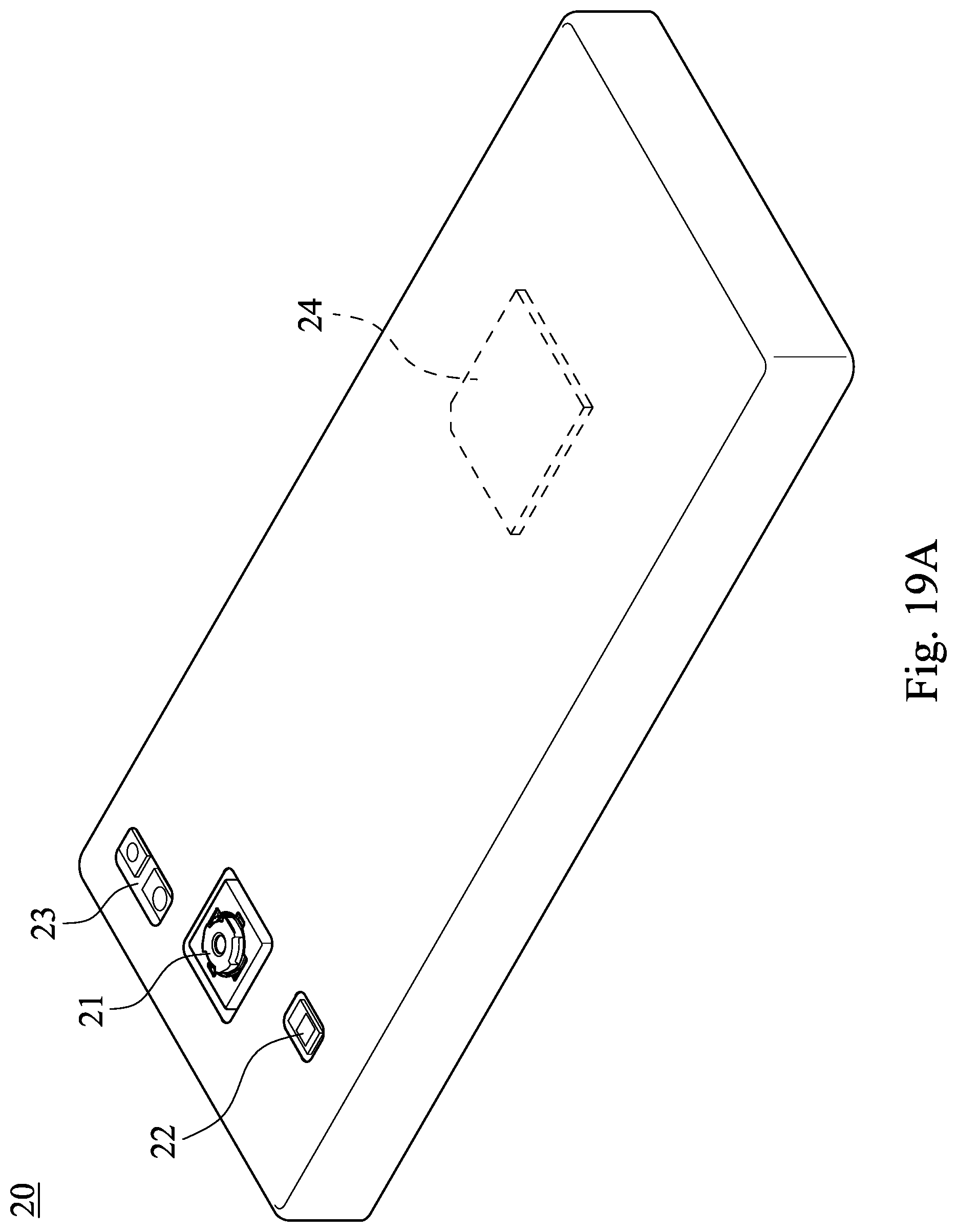
D00021
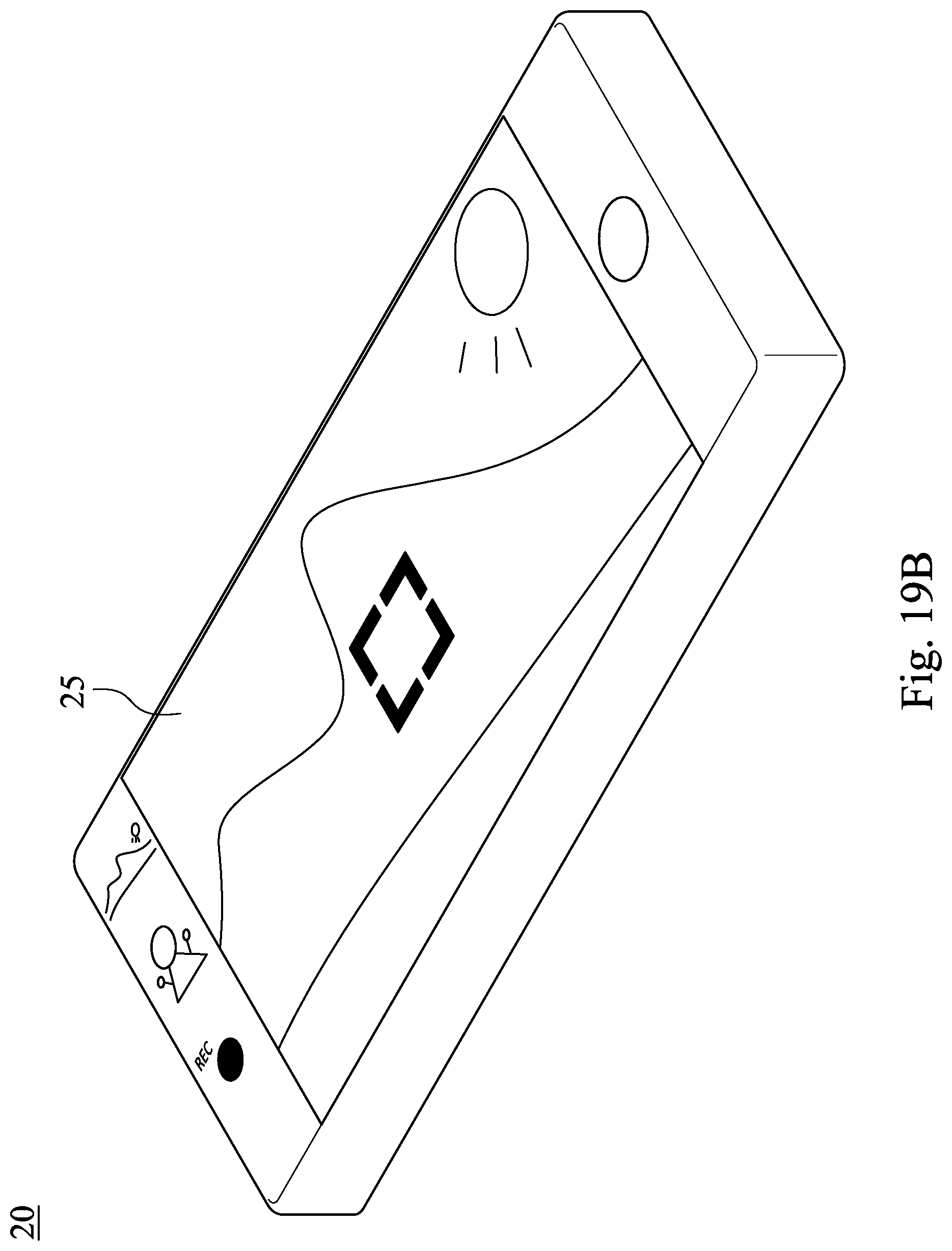
D00022

D00023

M00001

XML
uspto.report is an independent third-party trademark research tool that is not affiliated, endorsed, or sponsored by the United States Patent and Trademark Office (USPTO) or any other governmental organization. The information provided by uspto.report is based on publicly available data at the time of writing and is intended for informational purposes only.
While we strive to provide accurate and up-to-date information, we do not guarantee the accuracy, completeness, reliability, or suitability of the information displayed on this site. The use of this site is at your own risk. Any reliance you place on such information is therefore strictly at your own risk.
All official trademark data, including owner information, should be verified by visiting the official USPTO website at www.uspto.gov. This site is not intended to replace professional legal advice and should not be used as a substitute for consulting with a legal professional who is knowledgeable about trademark law.