Chair
Schmitz , et al.
U.S. patent number 10,653,249 [Application Number 16/129,934] was granted by the patent office on 2020-05-19 for chair. The grantee listed for this patent is Burkhard Schmitz, Carola Zwick, Roland Zwick. Invention is credited to Burkhard Schmitz, Carola Zwick, Roland Zwick.


View All Diagrams
| United States Patent | 10,653,249 |
| Schmitz , et al. | May 19, 2020 |
Chair
Abstract
A chair including a subframe, a seat element, a back element, a spring mechanism and an adjustment device. The spring mechanism includes a leaf spring, which is clamped on one side in the subframe, and a support, which is movable on a track between the leaf spring and the subframe. The adjustment device includes an adjustment member and a transmission mechanism. A movement of the adjustment member is translated into a movement of the support at a transmission ratio of between 1:0.5 and 1:4.
| Inventors: | Schmitz; Burkhard (Berlin, DE), Zwick; Carola (Berlin, DE), Zwick; Roland (Berlin, DE) | ||||||||||
|---|---|---|---|---|---|---|---|---|---|---|---|
| Applicant: |
|
||||||||||
| Family ID: | 58314206 | ||||||||||
| Appl. No.: | 16/129,934 | ||||||||||
| Filed: | September 13, 2018 |
Prior Publication Data
| Document Identifier | Publication Date | |
|---|---|---|
| US 20190029440 A1 | Jan 31, 2019 | |
Related U.S. Patent Documents
| Application Number | Filing Date | Patent Number | Issue Date | ||
|---|---|---|---|---|---|
| PCT/EP2017/056004 | Mar 14, 2017 | ||||
Foreign Application Priority Data
| Mar 14, 2016 [DE] | 10 2016 104 636 | |||
| Current U.S. Class: | 1/1 |
| Current CPC Class: | A47C 7/445 (20130101); A47C 7/441 (20130101); A47C 31/126 (20130101); A47C 1/03277 (20130101) |
| Current International Class: | A47C 1/00 (20060101); A47C 7/44 (20060101); A47C 31/12 (20060101); A47C 3/26 (20060101); A47C 3/025 (20060101); A47C 1/023 (20060101); A47C 1/032 (20060101) |
| Field of Search: | ;297/300.1-300.8,337 |
References Cited [Referenced By]
U.S. Patent Documents
| 4889385 | December 1989 | Chadwick |
| 4911501 | March 1990 | Decker |
| 5035466 | July 1991 | Mathews |
| 5046780 | September 1991 | Decker |
| 5048893 | September 1991 | Cowan |
| 5288138 | February 1994 | Stulik |
| 5348372 | September 1994 | Takamatsu |
| 5356199 | October 1994 | Elzenbeck |
| 5397165 | March 1995 | Grin |
| 5603551 | February 1997 | Sheehan |
| 6027168 | February 2000 | Crossman |
| 6135556 | October 2000 | Chu |
| 6193313 | February 2001 | Jonsson |
| 6250715 | June 2001 | Caruso |
| 6634711 | October 2003 | Phillips |
| 6688692 | February 2004 | Phillips |
| 6824215 | November 2004 | Koepke |
| 6871909 | March 2005 | Hobb |
| 6926361 | August 2005 | Link |
| 6986550 | January 2006 | Gevaert |
| 6994400 | February 2006 | Koepke |
| 7172250 | February 2007 | Wu |
| 7273253 | September 2007 | Deimen |
| 7341233 | March 2008 | McMains |
| 7380881 | June 2008 | Freed |
| 7625045 | December 2009 | Hatcher |
| 7806478 | October 2010 | Cvek |
| 7857390 | December 2010 | Schmitz |
| 7922248 | April 2011 | Aldrich |
| 7992937 | August 2011 | Plikat |
| 8210611 | July 2012 | Aldrich |
| 8419133 | April 2013 | Holt |
| 8469454 | June 2013 | Holt |
| 8991921 | March 2015 | Peterson |
| 9216673 | December 2015 | Braun |
| 9386858 | July 2016 | Chen |
| 9560917 | February 2017 | Roslund, Jr. |
| 2001/0050503 | December 2001 | Piretti |
| 2004/0183350 | September 2004 | Schmitz |
| 2006/0202530 | September 2006 | Lin |
| 2008/0084100 | April 2008 | Curiger |
| 2008/0258531 | October 2008 | Lu |
| 2012/0074749 | March 2012 | Hsiao |
| 2013/0069408 | March 2013 | Chen |
| 2014/0246890 | September 2014 | Lee |
| 10 2013 005 861 | Oct 2014 | DE | |||
| 2007/110732 | Oct 2007 | WO | |||
Other References
|
English translation of International Preliminary Report on Patentability (Chapter I) (Application No. PCT/EP2017/056004) dated Sep. 27, 2018, 6 pages. cited by applicant . International Search Report and Written Opinion (Application No. PCT/EP2017/056004) dated May 31, 2017. cited by applicant. |
Primary Examiner: White; Rodney B
Attorney, Agent or Firm: Burr & Brown, PLLC
Parent Case Text
CROSS REFERENCE TO RELATED APPLICATIONS
This application is a continuation of International Application No. PCT/EP2017/056004 filed Mar. 14, 2017, which designated the United States, and claims the benefit under 35 USC .sctn. 119(a)-(d) of German Application No. 10 2016 104 636.1 filed Mar. 14, 2016, 2015, the entireties of which are incorporated herein by reference.
Claims
The invention claimed is:
1. A chair comprising: a subframe; a seat element; a back element; a spring mechanism; and an adjustment device, wherein the spring mechanism comprises a leaf spring clamped on one side in the subframe, and a support movable on a track between the leaf spring and the subframe, wherein the adjustment device includes an adjustment member and a transmission mechanism, wherein the adjustment member is a shaft or linear guide mechanism, wherein the chair includes an electric drive for moving the adjustment member, wherein the electric drive includes an electric linear drive or an electric rotary drive, wherein the transmission mechanism includes at least one of a rod assembly, a Bowden cable and a gear unit, and wherein the transmission mechanism is connected to the support and connected to the adjustment member, and wherein a movement of the adjustment member is translated into a movement of the support at a transmission ratio of between 1:0.5 and 1:4.
2. The chair according to claim 1, wherein the track is a curved surface adapted to a curved progression of the respectively associated leaf spring so that a movement space between the track and a bottom surface of the leaf spring permits movement of the support, unobstructed by the leaf spring, between a normal position of the support and an end position of the support, insofar as a rear swing arm is free of a load produced by a user leaning back against the back element, and wherein a distance measured in each case in a radial direction between the track and the associated leaf spring is constant in the entire movement space.
3. The chair according to claim 1, wherein the electric drive includes an energy storage mechanism for electric energy, wherein the electric drive includes an actuating device and/or a receiver for radio signals and the chair includes an electric generator, wherein the generator generates electric energy from a relative movement which occurs between individual components of the chair when the chair is used, and feeds it into the energy storage mechanism.
4. The chair according to claim 1, wherein the spring mechanism includes the first leaf spring and a second leaf spring, wherein the second leaf spring supports the back element in a normal position of the chair in which the back element is free of loads produced by a sitting person, and wherein the first leaf spring, in addition to the second leaf spring, supports the back element in an operating position that deviates from the normal position in which the back element is loaded by a person sitting and leaning back.
5. The chair according to claim 4, wherein the first leaf spring and the second leaf spring form a spring assembly and are connected together at a connection point in a region in which said spring assembly is fastened to the subframe and wherein the first leaf spring is tapered adjacent to the connection point.
6. The chair according to claim 4, the first leaf spring is supported by the first support and wherein the second leaf spring is supported by a second support, wherein the first support is slidable under the first leaf spring and wherein the second support is either fixed under the second leaf spring or is slidable under the second leaf spring independently of the first support.
7. The chair according to claim 6, wherein the first support is adjustable by the first adjustment device and wherein the second support is adjustable by a second adjustment device.
8. The chair according to claim 1, wherein the transmission mechanism comprises a pivot lever which is driven directly or indirectly by the adjustment member, wherein the transmission mechanism comprises a rolling-contact wheel with a toothing, which is driven directly or indirectly by the pivot lever, wherein the support comprises a toothed rod, wherein the rolling-contact wheel engages with its toothing in the toothed rod of the support, wherein the subframe comprises a toothed rod, and wherein the rolling-contact wheel engages with its toothing in the toothed rod of the subframe.
9. The chair according to claim 8, wherein the transmission mechanism comprises a connecting rod, wherein the pivot lever is connected to a first end of the connecting rod for rotation about a first rotational axis, wherein the rolling-contact wheel is connected to a second end of the connecting rod for rotation about a second rotational axis, wherein the rolling-contact wheel is pulled or pushed by the connecting rod over the toothed rod of the subframe during a rotation movement of the pivot lever and, in the process, the support located between the leaf spring and the rolling-contact wheel is entrained and moved by the rotating and moving rolling-contact wheel.
10. The chair according to claim 9, wherein the pivot lever is mounted on the subframe pivotably about a pivot axis, wherein the pivot axis of the pivot lever and the first rotational axis of the connecting rod and the second rotational axis of the connecting rod extend parallel to each other.
11. The chair according to claim 8, wherein the transmission mechanism comprises a Bowden cable or a gear unit, wherein the Bowden cable or the gear unit is connected to the adjustment member and to the pivot lever, wherein the Bowden cable or the gear unit is secured on the pivot lever eccentrically with respect to the pivot axis of the pivot lever with an eccentricity.
12. The chair according to claim 1, wherein the transmission mechanism comprises a rolling-contact wheel with a toothing, wherein the rolling-contact wheel is directly or indirectly connected to the adjustment member and is pulled or pushed by means of the latter over a toothed rod of the subframe, wherein the rolling-contact wheel engages with its toothing in a toothed rod of the support and thereby entrains and moves the support located between the leaf spring and the rolling-contact wheel.
Description
FIELD OF THE INVENTION
The present invention relates to a chair.
BACKGROUND OF THE INVENTION
DE 10 2013 005 861 A1 discloses a chair which includes a subframe, a seat element, a back element, a spring mechanism and an adjustment device, the spring mechanism including a leaf spring which is clamped on one side in the subframe and a support which is movable on a track between the leaf spring and the subframe and the adjustment device including an adjustment member and a transmission mechanism.
Modern office premises are often increasingly utilized in such a manner that individual employees do not have a fixed workstation, but work at different workstations over the year depending on operational requirements. As a result, comparatively often the employees have to adjust a chair that is available at the respective workstation to their individual requirements. The operation is time-consuming and is consequently often ignored such that an individual employee may possibly sit on an insufficiently adjusted chair for extended periods and, as a result, may suffer from health problems in the long term.
SUMMARY OF THE INVENTION
It is the object of the present invention to propose a chair which is rapidly adjustable to individual requirements by different users.
Corresponding to the present invention, a movement of the adjustment member is translated into a movement of the support at a transmission ratio of between 1:0.5 and 1:4. As a result, it is possible for a user to perform an adjustment of the chair with minimal time expended. It is consequently possible for even a very light user to convert a chair that has been adjusted to a very heavy user optimally to his requirements in a short time.
It is provided that the track is realized as a curved surface which is adapted in such a manner to a curved progression of the respectively associated leaf spring that a movement space, realized between the track and a bottom surface of the leaf spring, permits movement of the support, unobstructed by the leaf spring, between a basic position of the support and an end position of the support, insofar as the rear swing arm is free of a load produced by a user leaning back against the back element and that a distance measured in each case in the radial direction between the track and the associated leaf spring is constant in the entire movement space. As a result of providing a space of this type for the support, the friction forces, which the support has to overcome when it moves between its different positions, can be reduced to a minimum, such that the support is able to be slid into all positions with little effort required and, when the back element is loaded, the leaf spring is placed without any considerable delay onto the support such that the support force preselected by the respective position of the support is available virtually immediately.
It is additionally provided to realize the adjustment member as a shaft or linear guide mechanism and to provide the chair with a drive for moving the adjustment member, the transmission mechanism including a rod assembly and/or a Bowden cable and/or a gear unit, wherein the transmission mechanism is connected to the support and wherein the transmission mechanism is connected to the adjustment member. As a result, a rotational movement initiated in the adjustment member or a sliding movement initiated in the adjustment member can be converted in a technically simple manner into a movement of the support.
It is provided to realize the drive as a manual drive and to provide it with a slider or a rotary knob by means of which the adjustment member can be acted upon to adjust the support.
It is also provided to realize the drive as an electric drive and to provide the drive with an electric linear drive or with an electric rotary drive. As a result, a motor-driven adjustment of the position of the support is possible such that a manual rotary movement or sliding movement to adjust the support is not required.
In addition, it is provided to fit the electric drive with an energy storage mechanism for electric energy, wherein the electric drive includes an actuating device and/or a receiver for radio signals and wherein the chair includes, in particular, an electric generator, wherein the generator generates, in particular, energy from a relative movement which occurs between individual components of the chair when the chair is used, and feeds it into the energy storage mechanism. As a result, the chair can be made into a stand-alone device which can be conveniently adjusted by means of an actuating device, such as, for example, an electric button that is arranged within visual range, or in a remote-controlled manner, e.g. by means of a smartphone. As a result of fitting the chair with a generator, the chair, with its electric drive, is made into an item of furniture which is energy self-sufficient and which does not require any service with regard to replacing or charging its energy storage mechanism and consequently, in spite of the electric drive, does not give rise to any follow-up costs.
It is also provided that the spring mechanism includes the mentioned first leaf spring and a second leaf spring, wherein the second leaf spring supports the back element in a normal position of the chair in which the back element is free of loads produced by a sitting person, and wherein the first leaf spring, in addition to the second leaf spring, supports the back element in an operating position in which the back element is loaded by a person sitting and leaning back. As a result, it is possible to hold the back element reliably in its non-loaded position such that too strong a deformation of the first leaf spring in this position is reliably avoided and consequently a low-friction movement of the support under the first leaf spring is ensured.
In this connection, it is provided to form a spring assembly by means of the first leaf spring and the second leaf spring and to connect both of these together at a connection point, in particular, in a region in which they are fastened to the subframe, the first leaf spring comprising a tapering adjacent to the connection point. As a result, the assembly of the chair is made easier and, in addition, the shaping of the first leaf spring has a positive effect on the desired support behaviour--as has been ascertained in tests.
It is also provided to support the mentioned first leaf spring by the mentioned first support and the second leaf spring by a second support, wherein the first support is slidable under the first leaf spring and wherein the second support is either fixed under the second leaf spring or is slidable under the second leaf spring independently of the first support. As a result of the support associated with the second leaf spring, the force, at which the second leaf spring supports the back element, is able to be chosen corresponding to requirements. Where the second support is adjustable, it is possible to adapt the force at which the second leaf spring supports the back element. This is, for example, advantageous when a weight of the back element is subsequently increased, for example, as a result of attaching a headrest.
It is also provided that that the mentioned first support is adjustable by the mentioned first adjustment device and that the mentioned second support is adjustable by means of a second adjustment device. In this way, adjustment of the second support can also be carried out in a convenient manner.
It is moreover provided that the transmission mechanism comprises a pivot lever which is driven directly or indirectly by the adjustment member, that the transmission mechanism comprises a rolling-contact wheel of a toothing, which is driven directly or indirectly by the pivot lever, and that the support comprises a toothed rod, wherein the rolling-contact wheel engages with its toothing in the toothed rod of the support, and that the subframe comprises a toothed rod, wherein the rolling-contact wheel engages with its toothing in the toothed rod of the subframe. Such a transmission mechanism can be of a compact design, such that it can be easily installed in the region of a carrier of a subframe of a chair.
In addition, it is provided that the transmission mechanism comprises a connecting rod, wherein the pivot lever is connected to a first end of the connecting rod for rotation about a first rotational axis, wherein the rolling-contact wheel is connected to a second end of the connecting rod for rotation about a second rotational axis, wherein the rolling-contact wheel is pulled or pushed by the connecting rod over the toothed rod of the subframe during a rotation movement of the pivot lever and, in the process, the support located between the leaf spring and the rolling-contact wheel is entrained and moved by the rotating and moving rolling-contact wheel. Through the use of a connecting rod as an intermediate member of the transmission mechanism, the pivoting movement of the pivot lever can be converted with minimal structural complexity into a linear movement.
Through a parallel arrangement of the pivot axis of the pivot lever and of the first rotational axis of the connecting rod and the second rotational axis of the connecting rod, the structure of the transmission mechanism is kept simple and smooth-running.
It is also provided that the transmission mechanism comprises a Bowden cable or a gear unit, wherein the Bowden cable or the gear unit is connected to the adjustment member and to the pivot lever, wherein the Bowden cable or the gear unit is secured on the pivot lever eccentrically with respect to the pivot axis of the pivot lever with an eccentricity. Through the choice of the eccentricity, the transmission ratio can be easily changed and adapted to different design forms of a chair.
Finally, it is also provided that the transmission mechanism comprises a rolling-contact wheel with a toothing, wherein the rolling-contact wheel is directly or indirectly connected to the adjustment member and is pulled or pushed by means of the latter over a toothed rod of the subframe, wherein the rolling-contact wheel engages with its toothing in a toothed rod of the support and thereby entrains and moves the support located between the leaf spring and the rolling-contact wheel. Such a transmission mechanism can be of a compact design, such that it can be easily installed in the region of a carrier of a subframe of a chair.
A transmission ratio in the sense of the present invention is to be understood as both a conversion of the speed of the drive into a faster speed of the support and a conversion of the speed of the drive into an identical speed of the support, and also as a conversion of the speed of the drive into a slower speed of the support.
BRIEF DESCRIPTION OF THE DRAWINGS
Further details of the present invention are described in the drawing by way of schematically shown exemplary embodiments.
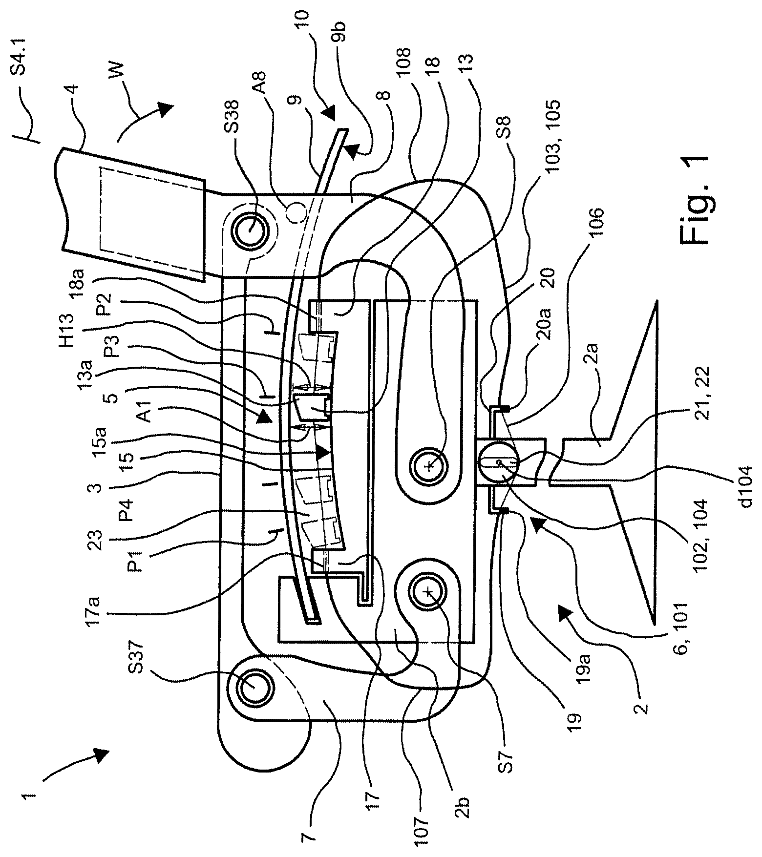
FIG. 1 shows a schematic side view of a first realization variant of a chair according to the present invention;
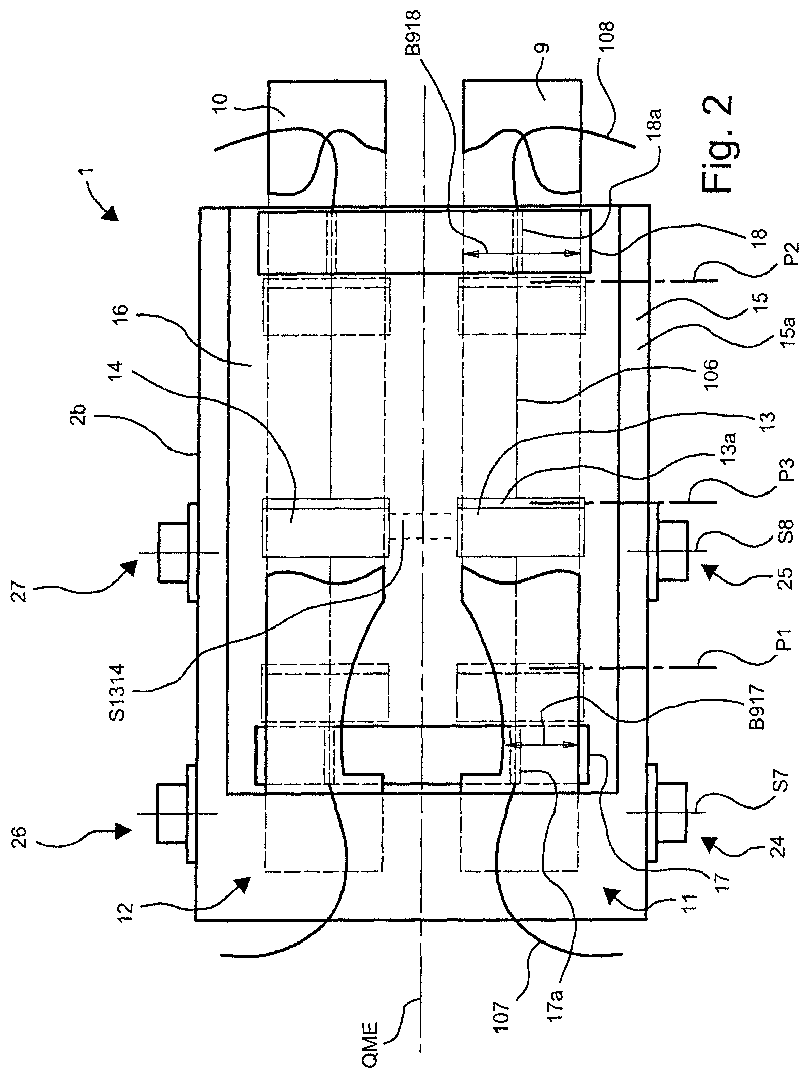
FIG. 2 shows a schematic top view of the first realization variant of the chair according to the present invention with the back element blanked out and the seat element blanked out;
FIG. 3 shows a schematic side view of a second realization variant of a chair according to the present invention;
FIG. 4 shows a schematic side view of a third realization variant of a chair according to the present invention;
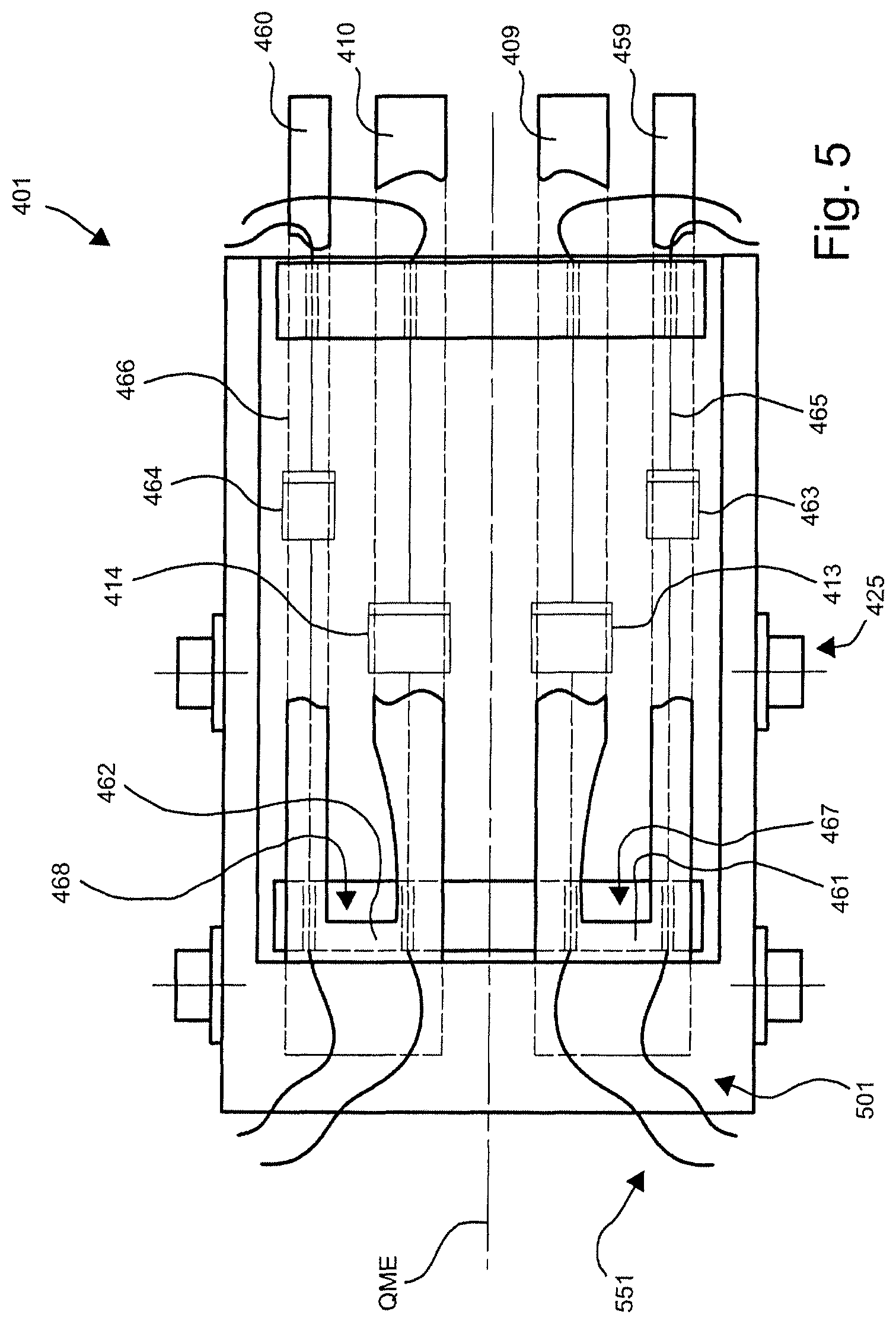
FIG. 5 shows a schematic top view of the third realization variant of the chair according to the present invention with the back element blanked out and the seat element blanked out;
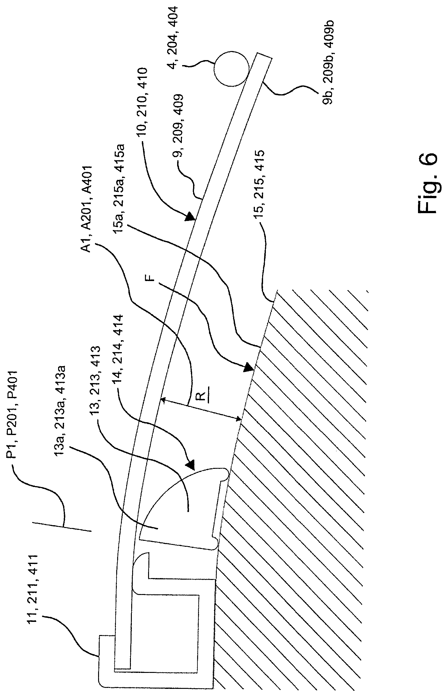
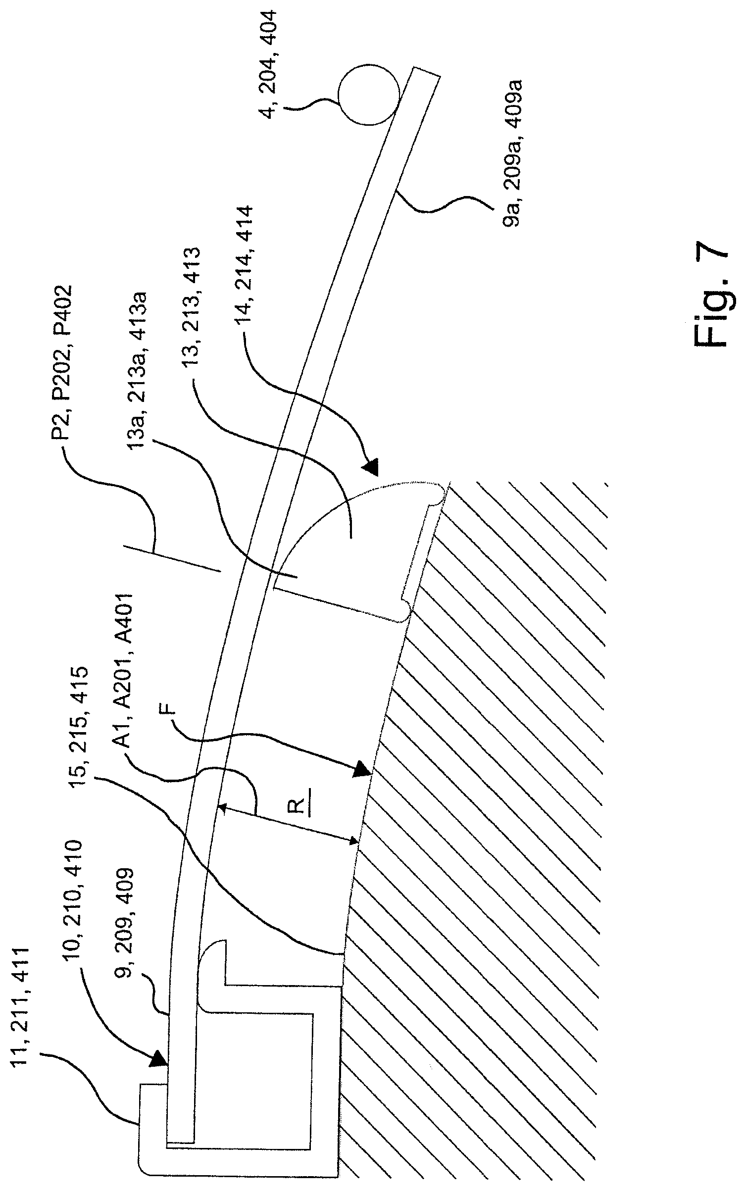
FIGS. 6 and 7 show schematic representations of a support located between a leaf spring and a track;
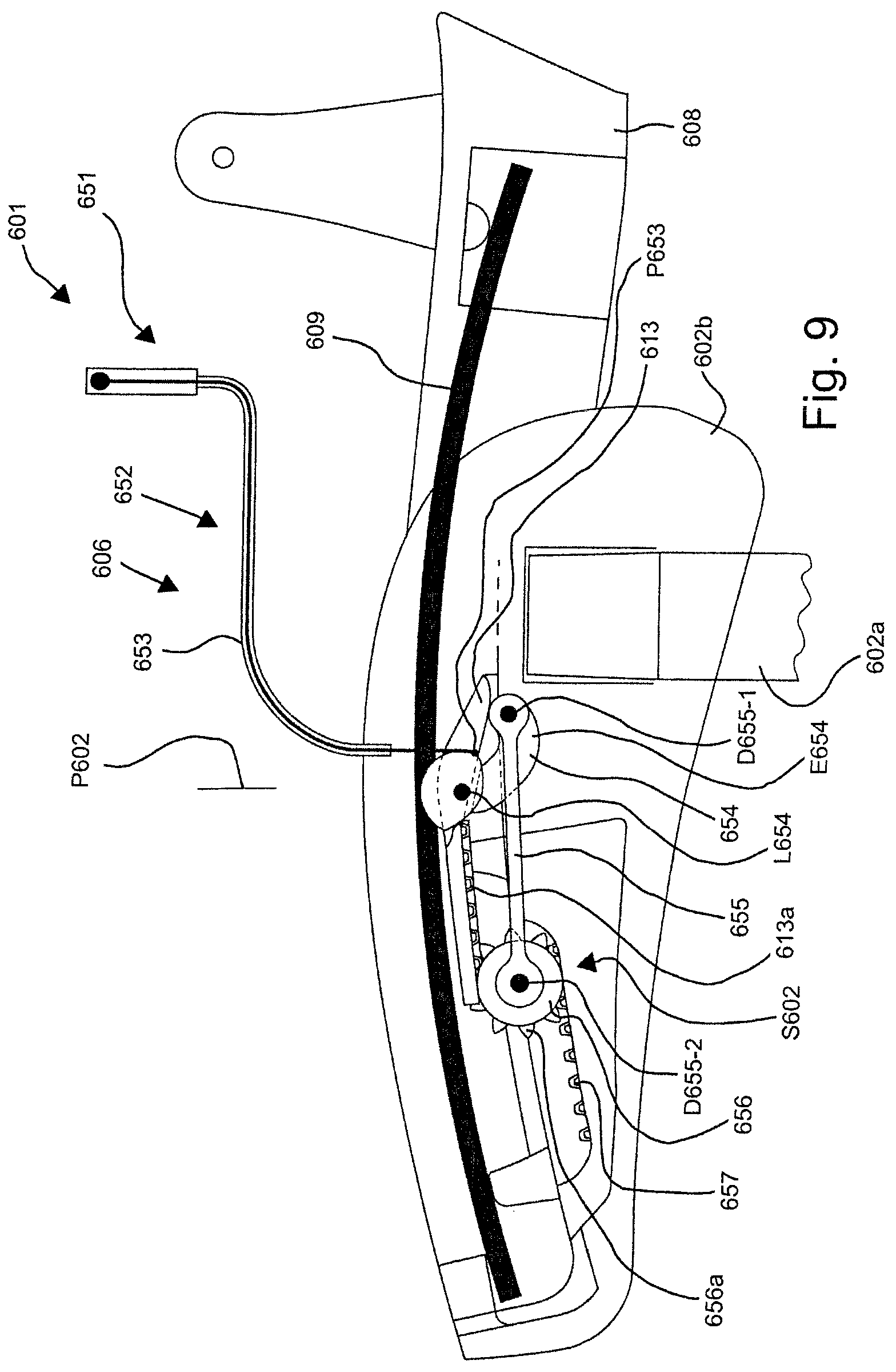
FIGS. 8 and 9 show schematic side views of a fourth realization variant of a chair according to the present invention, in a setting for persons of light weight and in a setting for persons of heavy weight; and
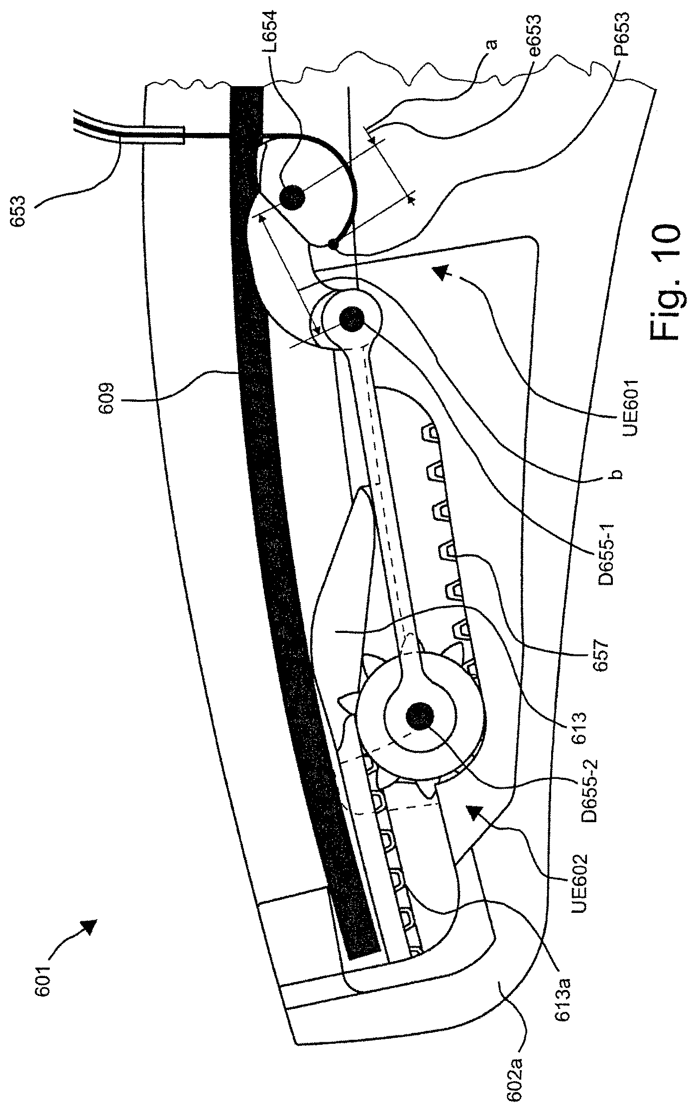
FIGS. 10 and 11 show details from FIGS. 8 and 9.
DETAILED DESCRIPTION OF THE INVENTION
FIG. 1 shows a schematic side of a chair 1 which includes a subframe 2, a seat element 3, a back element 4, a spring mechanism 5 and an adjustment device 6. The subframe 2 includes a base element 2a and a carrier 2b. The chair 1 additionally includes a front swing arm 7 and a rear swing arm 8 which is realized as a back connection. In this connection, the base element 2a is connected to the carrier 2b. The back element 4 is pivotally mounted on the carrier 2b by means of the swing arm 8 and, in addition, the seat element 3 is pivotally mounted on the carrier 2b by means of the front swing arm 7. The front swing arm 7 is connected to the carrier 2b so as to be pivotable about a pivot axis S7 and the rear swing arm 8 is connected to the carrier 2b so as to be pivotable about a pivot axis S8. The seat element 3 is connected to the swing arm 7 so as to be pivotable about a pivot axis S37. In addition, the seat element 3 is connected to the back connection 8 so as to be pivotable about a pivot axis S38. The seat element 3 and the back element 4 are connected together so as to be rotatable by means of the pivot axis S38. The carrier 2b receives the spring mechanism 5.
FIG. 2 shows a schematic top view of the first realization variant of the chair 1 according to the present invention with the back element blanked out and with the seat element blanked out. It can be seen from the top view that the chair 1 is realized in a substantially mirror-symmetrical manner with respect to a transverse centre plane QME. Substantially the region of the chair 1 that in the representation in FIG. 2 is located below the transverse centre plane QME, which is marked by a broken line, is described in a corresponding manner below. Nevertheless, reference is also made again and again to components located above the transverse centre plane QME which are completely hidden, as a rule, in the side view.
The carrier 2b includes a leaf spring 9 and a leaf spring 10, which is hidden by the leaf spring 9 in the view in FIG. 1. As can be seen in FIG. 2, the leaf springs 9, 10 are clamped on one side in the receiving mechanism 11, 12 of the carrier 2b. In addition, the spring mechanism 5 includes two supports 13, 14, tracks 15, 16, a front stop 17 and a rear stop 18. The supports 13, 14 are movable on the tracks 15 or 16 under the leaf spring 9 or 10 between a front position or normal position P1 marked by way of the broken line and a rear position or end position P2 marked by a broken line, such that the leaf spring 9 or 10 supports a tilting back of the back element 4 in a direction of rotation w (see FIG. 1), which is caused by a person leaning back against the back element 4, by means of the rear swing arm 8 which is supported by way of a stop A8 on the leaf springs 9 and 10.
By means of the adjustment device 6, the support 13, which is in a centre position P3 shown by way of continuous lines, is movable as an option into the named extreme position P1, in which the support 13 causes the leaf springs 9 to provide the back element 4 with only a small amount of support, into the named extreme position P2 in which the support 13 causes the leaf springs 9 to provide the back element 4 with a large amount of support, and into all positions lying in between that are not marked in any more detail. In this connection, the centre position P3 of the supports 13, 14 shown in FIG. 2 does not concur completely with the centre position P3 shown in FIG. 1. A fourth position P4 lying between the positions P1 and P3 is marked as an example by way of broken lines in FIG. 1 as further position P4.
The adjustment device 6 is realized as a mechanical adjustment device 101 and includes an adjustment member 102 and a transmission mechanism 103. The adjustment member 102 is realized as a shaft 104 which is rotatable about a rotational axis d104, and the transmission mechanism 103 is realized as a Bowden cable 105. In this connection, the Bowden cable 105 includes a wire cable 106 and two sleeves 107, 108. The wire cable 106 is fixed on the support 13 and is run between the track 15 and the leaf spring 9 through a through-bore 17a of the front stop 17. In addition, the wire cable 106 extends through the first sleeve 107 which is laid between the front stop 17 and a first holder 19 by way of a through-bore 19a. The wire cable 106 then leaves the first sleeve 108, runs through the through-bore 19a and wraps around the shaft 104 that forms the adjustment member 102 in order then to enter through a through-bore 20a of a second holder 20 into the second sleeve 108 which is laid between the second holder 20 and the rear stop 18. The wire cable 106 then leaves the second sleeve 108 through a through bore 18a realized in the rear stop 18 and runs between the track 15 and the leaf spring 9 to the support 13 on which it is fixed. The two holders 19 and 20 are fixed on the base element 2a.
A drive 21 for the adjustment device 101 is formed by a rotary knob 22 which is connected to the adjustment member 102 that is realized as the shaft 104. As a result of rotating the rotary knob 22 to the left about the rotational axis d104, the support 13 is pulled by the wire cable 106 out of its position P3 in the direction of the position P1 or P3. As a result of rotating the rotary knob 22 to the right about the rotational axis d104, the support 13 is pulled by the wire cable 106 out of its position P3 in the direction of the position P2. Here, a diameter of the shaft 104, over which the wire cable 106 is guided, is chosen such that about 1.5 revolutions of the shaft 104 are sufficient to move the support 13 from the position P1 to the position P2. To this extent, there is here a transmission ratio of about 1:0.7.
In a non-loaded position S4.1 (see FIG. 1) of the back element 4, in which the back element 4 is not loaded by a person leaning back, a top surface 15a of the track 15 and a bottom surface 9b of the leaf spring 9 are matched to one another in such a manner that between them is formed a space 23 which permits displacement of the support 9 from its position P1 into its position P2 without it grinding against the bottom surface 9b of the leaf spring 9 with its head 13a and as a result being braked. In other words, this means that a distance A that is measured radially with respect to a respective curvature of the track 15 between the top surface 15a of the track 15 and the bottom surface 9b of the leaf spring 9 is greater than a maximum height H13 of the support 13. This ensures that, in the non-loaded position S4.1 of the back element 4, the support 13 can be moved by the adjustment device 6 or 101 in an unobstructed manner between the position P1 and the position P2 such that the support 13 is able to be positioned at an expenditure of force which is free of braking forces resulting from the weight of a person.
The first realization variant shown in FIGS. 1 and 2 obviously also includes an adjustment device for the support 14. In this connection, it is provided according to a first realization variant to realize the adjustment device in an analogous manner to the adjustment device described and to connect the shafts of the two adjustment devices together such that both supports are adjustable together as an option by one of the rotary knobs. According to a second realization variant, it is also provided to wrap the wire cable of the Bowden cable of the second adjustment device also about the shaft of the first adjustment device such that both supports are able to be moved by means of the shaft of the first adjustment device.
According to a further realization variant, it is also provided--as marked in FIG. 2 by way of broken lines--to connect the two supports 13, 14 by means of a web S1314 and to provide an adjustment device which is coupled to the web S1314 such that the two supports 13, 14 are moved together by the web S1314.
As can be seen from the representation in FIG. 2, the leaf springs 9, 10 are realized in each case tapering toward the receiving mechanism 11, 12 such that a width B918, which the leaf spring 9 comprises in the region of the rear stop 18, is at least 1.5 times greater than a width B9017, which the leaf spring 9 comprises in the region of the front stop 17. Two lugs 24, 25 and 25, 27 are arranged in each case at the side of the carrier 2b, by means of which lugs the pivot axes S7, S8 the swing arms 7, 8 of the chair 1 are formed.
FIG. 3 shows a second realization variant of a chair according to the present invention as the chair 201. Reference is initially made to the description regarding the chair 1 shown in FIG. 1, the comparable reference numerals from the numeral series 1 to 99 being increased in each case by 200. The adjustment device 206 is also realized as a mechanical adjustment device 301, but has a different technical design.
The adjustment device 301 includes an adjustment member 302 and a transmission mechanism 303. The adjustment mechanism 302 is realized as a linear guide 304 and the transmission mechanism 303 is realized as a Bowden cable 305. In this connection, the Bowden cable 305 includes a wire cable 306 and two sleeves 307, 308. The wire cable 306 is fixed on the support 213 and is run between the track 215 and the leaf spring 209 through a through-bore 217a of the front stop 217. In addition, the wire cable 306 extends through the first sleeve 307 which is laid between the front stop 217 and a linear guide housing 229. The wire cable 306 leaves the first sleeve 308 and runs through an inlet bore 229a into the linear guide housing 229 and is guided by the linear guide 304 forming the adjustment member 302 in order then to enter through an outlet bore 229b of the linear guide housing 229 into the second sleeve 308 which is laid between the second holder 220 and the rear stop 218. The wire cable 306 then leaves the second sleeve 308 through a through-bore 218a realized in the rear stop 218 and runs between the track 215 and the leaf spring 209 to the support 213 on which it is fixed.
A drive 221 for the adjustment device 301 is formed by a slider 228 which is guided in the linear guide 304 forming the adjustment member 302 and is fixedly connected to the wire cable 306. As a result of sliding the slider 228 to the left, the support 213 is pulled by the wire cable 306 to the right out of its position P203 in the direction of the position or end position P202. As a result of sliding the slider 228 to the right, the support 213 is pulled to the left by the wire cable 306 out of its position P203 in the direction of the position or normal position P201.
In the top view, the second realization variant of the chair shown in FIG. 3 corresponds to FIG. 2.
FIG. 4 shows a third realization variant of a chair according to the invention as the chair 401. Reference is initially made to the description regarding the chair 1 shown in FIG. 1, the comparable reference numerals from the numeral series 1 to 99 being increased in each case by 400. The adjustment device 406 is realized as an electro-mechanical adjustment device 501.
The adjustment device 501 includes an adjustment member 502 and a transmission mechanism 503. The adjustment mechanism 502 is realized as a linear guide 504 and the transmission mechanism 503 is realized as a Bowden cable 505. In this connection, the Bowden cable 505 includes a wire cable 506 and two sleeves 507, 508. The wire cable 506 is fixed on the support 413 and is run between the track 415 and the leaf spring 409 through a through-bore 417a of the front stop 417. In addition, the wire cable 506 extends through the first sleeve 507 which is laid between the front stop 417 and a linear guide housing 429 by way of an inlet bore 429a. The wire cable 506 then leaves the first sleeve 508, runs through the inlet bore 429a into the linear guide housing 429 and is guided by the linear guide 504 forming the adjustment member 502 in order then to enter through an outlet bore 429b of the linear guide housing 429 into the second sleeve 508 which is laid between the linear guide housing 429 and the rear stop 418. The wire cable 506 then leaves the second sleeve 508 through a through-bore 418a realized in the rear stop 418 and runs between the track 415 and the leaf spring 409 to the support 413 on which it is fixed.
A drive 421 for the adjustment device 501 is formed by an electric drive 430 which is guided in the linear guide 504 forming the adjustment member 502. To this end, the electric drive 430 is realized with part of its housing 431 as a slider 432. The electric drive 430 includes a toothed wheel 433 which it drives by way of its motor shaft 434. The linear guide housing 429 includes a toothed rod 429c in which the electric drive 430 engages by way of its toothed wheel 433. In dependence on a direction of rotation of the toothed wheel 433, the electric drive 430, which is guided in the linear guide 504, can be moved to the left or the right in the linear guide 504. As a result of moving the electric drive 430 to the left, the support 413 is pulled to the right by the wire cable 506 out of its position P403 in the direction of the position or end position P402. As a result of moving the electric drive 430 to the right, the support 413 is pulled by the wire cable 506 to the left out of its position P403 in the direction of the position or normal position P401. Two keys T401-1 and T401-2 are arranged on the carrier 402b of the chair 401. The keys are arranged in a power circuit between a rechargeable energy storage mechanism 435 and the electric drive 430. As a result of actuating the key T401-1, the support 413 is moved forward and as a result of actuating the key T401-2, the support is moved rearward. In this connection, the two keys form an actuating device BTE401. As an option, the chair 401 also includes an electric generator 436 which generates electric energy as a result of a relative movement between the lug 425 (see FIG. 5) and the rear swing arm 40 and feeds it into the rechargeable energy storage mechanism 435.
FIG. 5 shows a schematic top view of the third realization variant of the chair 401 according to the invention with the back element blanked out and with the seat element blanked out. It can be seen from the top view that the chair 401 is realized in a substantially mirror-symmetrical manner with respect to a transverse centre plane QME. Substantially the region of the chair 1 that is located in the representation in FIG. 2 below the transverse centre plane QME which is marked by a broken line is described in a corresponding manner below. Nevertheless, reference is also made again and again to components located above the transverse centre plane QME which are completely hidden, as a rule, in the side view.
Along with the first leaf springs 409, 410, the spring mechanism 405 includes second leaf springs 459 and 460. The first leaf spring 410 and the second leaf spring 459 form a spring assembly 461. The first leaf spring 410 and the second leaf spring 459 form a further spring assembly 462. An own support 463 or 464 is assigned in each case to the second leaf springs 459 and 460. In this connection, the second leaf springs 459, 460 serve for the purpose of supporting the back element 404 (see FIG. 4) in its initial position or normal position or starting position S404.1, in which it is shown in FIG. 4 and in which it is not loaded by a person leaning back, such that the supports 413 or 414 assigned to the first leaf springs 409, 410 are able to be moved in a non-obstructed manner by the first leaf springs 409, 410 between their extreme positions P401 and P402 when the chair 410 is not loaded or when a user only loads the seat element 3 without loading the back element 4.
In FIG. 5, further Bowden cables 465, 466, which are assigned to the supports 463 and 464, indicate that the supports 463, 464 are also able to be adjustable as an option. As a result, fine-adjustment of the chair 401 is made possible, by way of which the spring force of the leaf spring 459 or 460 is able to be readjusted.
As shown in FIG. 5, it is also provided that the leaf springs 409 and 459 or 410 and 460, which form the spring assemblies 461 and 462, are connected at connection points 467, 468 and form the respective one-piece spring assemblies 461 and 462. In this connection, the first leaf springs 409 or 410 of the spring assemblies 461 or 462 are in particular realized in a tapered manner adjoining the connection points 467 or 468. With regard to an adjustability of the supports 413, 414, which are arranged under the leaf springs 409, 410, reference is made to the description concerning FIG. 2. The support 413 is adjustable by means of the first adjustment device 501 and the second support 463 is adjustable, insofar as adjustability is provided, by means of a second adjustment device 551.
It is obviously possible to combine each of the three designs of the chair shown in FIGS. 1, 3 and 4 with each of the two designs shown in FIGS. 2 and 5, at least one adjustment device being provided in each case.
In FIGS. 6 and 7, in schematic views with reference to FIGS. 1, 3 and 4, it is shown that the tracks 15, 215, 415 comprise a curved progression which is adapted to a curved progression of the leaf springs 9, 10 or 209, 210 or 409, 410. In this connection, the adaptation is performed such that the support 13 or 213 or 413 or 14 or 214 or 414, which is situated initially close to the receiving mechanism 11 or 211 or 411 for the leaf springs 9, 10 or 209, 210 or 409, 410, is able to be moved out of a position P1 or P201 or P410 shown in FIG. 6 into a position P2 or P202 or P402 shown in FIG. 7 without the support 13 or 213 or 412 being obstructed or braked by the leaf spring 9 or 209 or 409 during its movement. Located opposite the receiving mechanism 11 or 211 or 411, the back element 4 or 204 or 404, which is supported in its normal position on the leaf spring 13 or 213 or 413, is symbolized in each case by way of a circle. As soon as the back element 4 or 204 or 404 is loaded by a person leaning back, the leaf spring 9 or 209 or 409 is placed onto the head 13a or 213a or 413a of the support 13 or 213 or 413. At this moment, the support 13 or 213 or 413 is in a position which produces the desired spring force of the leaf spring 9 or 209 or 409. By way of its top surface 15a or 215a or 415a, the track 15 or 215 or 415 consequently forms a curved surface F which is adapted in such a manner to a curved progression of the respectively assigned leaf spring 9 or 209 or 409 that a movement space R that is formed between the track 15 or 215 or 415 and the bottom surface 9b or 209b or 409b permits movement of the support 13 or 213 or 413, unobstructed by the leaf spring 9 or 209 or 409, between the first position P1 or P201 or P401 of the support 13 or 213 or 413 and the second position P2 or P202 or P402 of the support 13 or 213 or 413 insofar as the back element 4 or 204 or 404 is free from a load produced by a user leaning back against the back element 4 or 204 or 404. In addition, a distance A1 or A201 or A401 that is measured in each case in the radial direction between the track 16 or 216 or 416 and the assigned leaf spring 9 or 209 or 409 is constant in the entire movement space R.
FIGS. 8 to 11 show two schematic side views, and details of these side views, of a fourth realization variant of a chair 601 according to the present invention, in a setting for persons of low weight (FIGS. 8, 10) and a setting for persons of heavy weight (FIGS. 9, 10).
The chair 601 comprises an only partially indicated subframe 602. Analogously to the realization variant shown in FIG. 1, a seat element (not shown) and a back element (not shown) are articulated on this subframe 602. Moreover, the chair 601 comprises a spring mechanism 605 and an adjustment device 606. The subframe 602 comprises a partially indicated base element 602a and a carrier 602b. The chair 1 also comprises a rear swing arm 608 which is designed as a back connection and which bears on a leaf spring 609 clamped into the subframe 602. A pretensioning of the leaf spring 609 is determined by the positions P601, P602 which are adopted by a support 613 on a track 615 located between the leaf spring 609 and the subframe 602 (compare FIGS. 8 and 9). In FIG. 8, the support 613 stands in the forward position P601, which is also designated as a basic position, and, in FIG. 9, the support 613 stands in a rear position P602, which is also designated as an end position. In the forward position P601 of the support 613, the swing arm 608 for supporting the back element (not shown) against a person leaning back acquires only relatively weak support by the leaf spring 609 and is thus set for persons of light body weight, e.g. under 50 kg. In the rear position P602 of the support 613, the swing arm 608 for supporting the back element (not shown) against a person leaning back acquires only relatively strong support from the leaf spring 609 and is thus set for persons of heavy body weight, e.g. over 90 kg. By means of the adjustment device 606, the support 613 can be moved from the basic position P601 to the end position P602 and back and can also be moved to each intermediate position lying between these positions P601, P602. The adjustment device 606 comprises an adjustment member 651 and a transmission mechanism 652.
The adjustment member 651 comprises a linear guide 651a and a slider 651b. The transmission mechanism 652 comprises a Bowden cable 653, a pivot lever 654, a connecting rod 655 and a rolling-contact wheel 656 with a toothing 656a. The pivot lever 654 is mounted pivotably on the carrier 602b of the subframe 602 about a pivot axis L654 and can be pivoted about a pivot angle .alpha. of over 90.degree. by the adjustment member 651 by means of the Bowden cable 653, which is connected to the adjustment member 651 and to the pivot lever 654. Here, the Bowden cable 653, which can be actuated by hand by means of the slider 651b serving as drive 621, engages, eccentrically to the pivot axis L654, in a point of engagement P653 on the pivot lever 654 and is guided on the pivot lever 654 on a track B653 extending in a circle about the pivot axis L654. A free end E654 of the pivot lever 654 is connected to a first end 655-1 of the connecting rod 655 for rotation about a rotational axis D655-1. From a relationship in which there is a first distance a (see FIG. 10) between the pivot axis L654 and the point of engagement P654 and a second distance b (see FIG. 10) between the pivot axis L654 and the rotational axis D655-1, there derives a first transmission ratio UE601 with which the movement of the adjustment member 651 or of the Bowden cable 653 is converted by means of the pivot lever 654 into a movement of the connecting rod 655. In the embodiment shown, the first transmission ratio UE601 is about 1:2.
At a second end 655-2 of the connecting rod 655, the rolling-contact wheel 656 with its toothing 656a is arranged rotatably about a rotational axis D655-2. The rolling-contact wheel 656 is freely rotatable about the rotational axis D655-2 with respect to the connecting rod 655. The rolling-contact wheel 656 lies on a toothed rod 657, which is formed on the carrier 602b of the subframe 602. During a pivoting movement of the pivot lever 654 to the left about the pivot axis L654, the rolling-contact wheel 656 is pulled by the connecting rod 655 over the toothed rod 657 and in this case rolls along the latter. Lying opposite the toothed rod 657 is the support 613, which comprises a toothed rod 613a in which the rolling-contact wheel 656 likewise engages with its toothing 656a. If the rear swing arm 608 of the chair 601 is unloaded, the support 613 can be freely moved by the leaf spring 609 below the latter. Here, the rolling-contact wheel 656 interacts with the support 613 and the toothed rod 613a thereof in such a way that the rolling-contact wheel 656, e.g. in a movement perpendicular to the course and in the direction of the pivot axis L654 of the pivot lever 654, entrains the support 613 in the direction of the pivot axis L654 and at the same time as far as the pivot axis L654. Accordingly, the support 613 moves twice as fast and twice as far as the connecting rod 655. Thus, there is a second transmission ratio UE602 of 1:2, and a total transmission ratio of 1:4 is therefore obtained. If the rolling-contact wheel 656 is moved away from the pivot axis L654 from its position S602, which it occupies when the support 613 stands in the position P602, by means of a clockwise rotation of the pivot lever 654 about the pivot axis L654, the support 613 is also moved away from the pivot axis L654 and conveyed away, such that it is again in the position P601 at the end of the pivoting movement. The rolling-contact wheel 656 is then in a position S601 (see FIG. 8).
LIST OF REFERENCES
1 Chair 2 Subframe 2a Base element 2b Carrier 3 Seat element 4 Back element 5 Spring mechanism 6 Adjustment device 7 Front swing arm 8 Rear swing arm 9 Leaf spring 9b Bottom surface of 9 10 Leaf spring 11 Receiving mechanism for 9 on 2b 12 Receiving mechanism for 10 on 2b 13 Support 13a Head of 13 14 Support 15 Track 15a Top surface of 15 16 Track 17 Front stop 17a Through-bore 18 Rear stop 18a Through-bore 19 First holder 19a Through-bore 20 Second holder 20a Through-bore 21 Drive 22 Rotary knob 23 Space between 15 and 9 24, 25 Lug on 2b 26, 27 Lug on 2b A1 Distance between 15 and 9 A8 Stop on 8 H13 Height of 13 P1 Normal position/front position of 13 P2 End position/rear position of 13 P3 Centre position of 13 P4 Further position of 13 S7 Pivot axis S8 Pivot axis S37 Pivot axis S38 Pivot axis S1314 Web between 13 and 14 QME Transverse centre plane F Curved surface R Movement space w Direction of rotation 101 Adjustment device 102 Adjustment member 103 Transmission mechanism 104 Shaft 105 Bowden cable 106 Wire cable 107, 108 Sleeve d104 Rotational axis of 104 201 Chair 202 Subframe 202a Base element 202b Carrier 203 Seat element 204 Back element 205 Spring mechanism 206 Adjustment device 207 Front swing arm 208 Rear swing arm 209 Leaf spring 209b Bottom surface of 209 210 Leaf spring 211 Receiving mechanism for 209 on 202b 212 Receiving mechanism for 210 on 202b 213 Support 213a Head of 213 214 Support 215 Track 215a Top surface of 215 216 Track 217 Front stop 217a Through-bore 218 Rear stop 218a Through-bore 219 First holder 219a Through-bore 220 Second holder 220a Through-bore 221 Drive 222 Rotary knob 223 Space between 215 and 209 224, 225 Lug on 202b 226, 227 Lug on 202b 228 Slider 229 Linear guide housing 229a Inlet bore of 229 229b Outlet bore of 229 A201 Distance between 215 and 209 A208 Stop on 208 H213 Height of 213 P201 Normal position/front position of 213 P202 End position/rear position of 213 P203 Centre position of 213 P204 Further position of 213 S207 Pivot axis S208 Pivot axis S237 Pivot axis S238 Pivot axis 301 Adjustment device 302 Adjustment member 303 Transmission mechanism 304 Linear guide 305 Bowden cable 306 Wire cable 307, 308 Sleeve 401 Chair 402 Subframe 402a Base element 402b Carrier 403 Seat element 404 Back element 405 Spring mechanism 406 Adjustment device 407 Front swing arm 408 Rear swing arm 409 Leaf spring 409b Bottom surface of 409 410 Leaf spring 411 Receiving mechanism for 409 on 402b 412 Receiving mechanism for 410 on 402b 413 Support 413a Head of 413 414 Support 415 Track 415a Top surface of 415 416 Track 417 Front stop 417a Through-bore 418 Rear stop 418a Through-bore 419 First holder 419a Through-bore 420 Second holder 420a Through-bore 421 Drive 422 Rotary knob 423 Space between 415 and 409 424, 425 Lug on 402b 426, 427 Lug on 402b 428 Not occupied 429 Linear guide housing 429a Inlet bore of 429 429b Outlet bore of 429 429c Toothed rod on 429 430 Electric drive 431 Housing 432 Slider 433 Toothed wheel 434 Motor shaft 435 Energy storage mechanism 436 Generator 459 Second leaf spring 460 Second leaf spring 461 Spring assembly from 409 and 459 462 Spring assembly from 410 and 460 463 Support for 459 464 Support for 460 465 Bowden cable on 463 466 Bowden cable on 464 467 Connection point of 409 and 459 468 Connection point of 410 and 460 A401 Distance between 415 and 109 A408 Stop on 408 H413 Height of 413 P401 Normal position/front position of 413 P402 End position/rear position of 413 P403 Centre position of 413 P404 Further position of 413 S407 Pivot axis S408 Pivot axis S437 Pivot axis S438 Pivot axis BTE401 Actuating device TA401-1 Electric key TA401-2 Electric key 501 First adjustment device 502 Adjustment member 503 Transmission mechanism 504 Linear guide 505 Bowden cable 506 Wire cable 507, 508 Sleeve 551 Second adjustment device 601 Chair 601 602 Subframe 605 Spring mechanism 605 606 Adjustment device 602a Base element 602b Carrier 608 Rear swing arm 609 Leaf spring P601, P02 Positions of 613 613 Support 613a Toothed rod of 613 615 Track 621 Drive 651 Adjustment member 651a Linear guide 651b Slider 652 Transmission mechanism 653 Bowden cable 654 Pivot lever 655 Connecting rod 656 Rolling-contact wheel 656a Toothing of 656 657 Toothed rod 657 on 602 a Distance between L654 and P654 b Distance between L654 and D655-1 .alpha. Pivot angle UE601 First transmission ratio UE602 Second transmission ratio UE602 P653 Point of engagement of 653 on 654 B653 Track on 654 E654 Free end of 654 L654 Pivot axis L654 655-1 First end of 655 655-2 Second end of 655 D655-1 First rotational axis of 655 D655-2 Second rotational axis of 655
* * * * *
D00000
D00001
D00002
D00003
D00004
D00005
D00006
D00007
D00008
D00009
D00010
D00011
XML
uspto.report is an independent third-party trademark research tool that is not affiliated, endorsed, or sponsored by the United States Patent and Trademark Office (USPTO) or any other governmental organization. The information provided by uspto.report is based on publicly available data at the time of writing and is intended for informational purposes only.
While we strive to provide accurate and up-to-date information, we do not guarantee the accuracy, completeness, reliability, or suitability of the information displayed on this site. The use of this site is at your own risk. Any reliance you place on such information is therefore strictly at your own risk.
All official trademark data, including owner information, should be verified by visiting the official USPTO website at www.uspto.gov. This site is not intended to replace professional legal advice and should not be used as a substitute for consulting with a legal professional who is knowledgeable about trademark law.