Sterilizable handle actuating button integration
Sanders , et al.
U.S. patent number 10,650,988 [Application Number 16/146,072] was granted by the patent office on 2020-05-12 for sterilizable handle actuating button integration. This patent grant is currently assigned to AMERICAN STERILIZER COMPANY. The grantee listed for this patent is AMERICAN STERILIZER COMPANY. Invention is credited to Lance Clark Bellows, Michael Hollopeter, Jill Sanders, David A. Westenfelder, II.


View All Diagrams
| United States Patent | 10,650,988 |
| Sanders , et al. | May 12, 2020 |
Sterilizable handle actuating button integration
Abstract
A handle assembly comprised of a base and a detachable handle that mounts to the base. The base includes integrated electronics, such as switches. The detachable handle includes buttons for activating the switches.
| Inventors: | Sanders; Jill (Willoughby, OH), Westenfelder, II; David A. (Mantua, OH), Hollopeter; Michael (Kirtland, OH), Bellows; Lance Clark (Painesville, OH) | ||||||||||
|---|---|---|---|---|---|---|---|---|---|---|---|
| Applicant: |
|
||||||||||
| Assignee: | AMERICAN STERILIZER COMPANY
(Mentor, OH) |
||||||||||
| Family ID: | 67141116 | ||||||||||
| Appl. No.: | 16/146,072 | ||||||||||
| Filed: | September 28, 2018 |
Prior Publication Data
| Document Identifier | Publication Date | |
|---|---|---|
| US 20190214203 A1 | Jul 11, 2019 | |
Related U.S. Patent Documents
| Application Number | Filing Date | Patent Number | Issue Date | ||
|---|---|---|---|---|---|
| 15865333 | Jan 9, 2018 | 10321970 | |||
| Current U.S. Class: | 1/1 |
| Current CPC Class: | H01H 13/86 (20130101); A61B 90/30 (20160201); H01H 13/7006 (20130101); H01H 13/85 (20130101); H01H 13/807 (20130101); F21V 21/403 (20130101); F21V 23/04 (20130101); H01H 13/83 (20130101); F21W 2131/20 (20130101); H01H 2221/0702 (20130101); H01H 2219/046 (20130101); H01H 2215/004 (20130101); F21W 2131/205 (20130101); H01H 2221/09 (20130101); H01H 2221/066 (20130101); A61B 2090/308 (20160201); H01H 2223/028 (20130101) |
| Current International Class: | A45C 13/26 (20060101); H01H 13/807 (20060101); H01H 13/85 (20060101); H01H 13/86 (20060101); H01H 13/70 (20060101); F21V 21/40 (20060101); F21V 23/04 (20060101); A61B 90/30 (20160101); H01H 13/83 (20060101) |
References Cited [Referenced By]
U.S. Patent Documents
| 4316237 | February 1982 | Yamada et al. |
| 4621735 | November 1986 | Coon et al. |
| 4844252 | July 1989 | Barron et al. |
| 4878156 | October 1989 | Hallings et al. |
| 4885443 | December 1989 | Simcoe et al. |
| 5188454 | February 1993 | Quintanilla et al. |
| 5233271 | August 1993 | Huang et al. |
| 5561278 | October 1996 | Rutten |
| 6370735 | April 2002 | Horan et al. |
| 6402351 | June 2002 | Borders et al. |
| 6633328 | October 2003 | Byrd et al. |
| 6692141 | February 2004 | Jesurun et al. |
| 6715904 | April 2004 | Naughton |
| 6863422 | March 2005 | Jesurun et al. |
| 6909465 | June 2005 | Liang |
| 7144035 | December 2006 | Min |
| 7285741 | October 2007 | Kato |
| 7441923 | October 2008 | Hunerbein et al. |
| 8789243 | July 2014 | Denmark |
| 8833953 | September 2014 | Schmid et al. |
| 2003/0210559 | November 2003 | Jesurun et al. |
| 2011/0300505 | December 2011 | Jessop et al. |
| 2016/0192990 | July 2016 | Wang |
| 2018/0231225 | August 2018 | Kim |
Other References
|
Specialty Disposable Light Handle for use with Trumpf Medical.TM. ALC Plus Surgical Light product brochure, Hill-Rom, Feb. 27, 2015, pp. 1-2. cited by applicant . HarmonyAIR.RTM. M-Series Surgical Lighting System product brochure, STERIS Corporation, Apr. 2016, pp. 1-8. cited by applicant . FREE5.RTM. Camera System product brochure, STERIS Corporation, Apr. 2017, pp. 1-4. cited by applicant . iLED.TM. 7 Surgical Light product brochure, Trumpf Medical, Hill-Rom, Jan. 9, 2017, pp. 1-8. cited by applicant. |
Primary Examiner: Mah; Chuck Y
Attorney, Agent or Firm: Kusner & Jaffe
Parent Case Text
RELATED APPLICATIONS
This application is a continuation-in-part of U.S. application Ser. No. 15/865,333, filed Jan. 9, 2018, and is hereby fully incorporated herein by reference.
Claims
Having described the invention, the following is claimed:
1. A handle assembly for a lighting system, comprising: a base having a stem section that includes at least one contact element mounted thereto, each contact element having one or more switches; and a detachable handle mountable to the base, the handle comprising: an outer housing having a head portion and a body portion; and a button membrane having one or more button elements accessible through an opening formed in the outer housing, each button element being respectively aligned with one of said switches when the detachable handle is mounted to the base to allow engagement of the button elements with the switches, said button elements respectively having contact portions are at least partially translucent.
2. A handle assembly for a lighting system, comprising: a base having at least one contact element mounted thereto, each contact element having at least one switch; and a detachable handle mountable to the base, the handle having a button membrane that includes at least one button element for respectively engaging with the at least one contact element, said button element having a contact portion that is at least partially translucent, wherein the translucency of the contact portion is regionally varied in different regions to provide a contrast that depicts a symbol.
3. The handle assembly of claim 2, wherein said detachable handle includes an outer housing.
4. The handle assembly of claim 3, wherein the button membrane is fixed to the outer housing.
5. The handle assembly of claim 4, wherein said detachable handle includes a support frame that engages with the button membrane, said support frame attachable to the outer housing.
6. The handle assembly of claim 5, wherein the support frame is comprised of metal.
7. The handle assembly of claim 2, wherein said button membrane is formed of silicone rubber or an elastomer.
8. The handle assembly of claim 2, wherein said button membrane is illuminated.
9. A detachable handle mountable to a base having at least one contact element mounted thereto, each contact element having at least one or more switches, said handle comprising: an outer housing having a head portion and a body portion; and a button membrane having one or more button elements accessible through an opening formed in the outer housing, each button element being respectively aligned with one of said switches to allow engagement of the button elements with the switches, said button elements respectively having contact portions that are at least partially translucent.
10. A detachable handle mountable to a base having at least one contact element mounted thereto, each contact element having at least one switch, said handle comprising: a button membrane that includes at least one button element having (i) an engagement portion for engaging with the contact element of the base and (ii) a contact portion for activation of the button element, wherein the contact portion is at least partially translucent, and wherein the translucency of the contact portion is regionally varied to provide a contrast that depicts a symbol.
11. The detachable handle of claim 10, wherein said detachable handle further comprises an outer housing.
12. The detachable handle of claim 11, wherein the button membrane is fixed to the outer housing.
13. The detachable handle of claim 12, wherein said detachable handle further comprises a support frame that engages with the button membrane, said support frame attachable to the outer housing.
14. The detachable handle of claim 13, wherein the support frame is comprised of metal.
15. The detachable handle of claim 10, wherein said button membrane is formed of silicone rubber or an elastomer.
16. The detachable handle of claim 10, wherein said button membrane is illuminated.
Description
FIELD OF THE INVENTION
The present invention relates generally to a handle assembly for a lighting system, and more particularly to a handle assembly having a detachable handle that mounts to a base with integrated electronics.
BACKGROUND OF THE INVENTION
Some existing surgical lighting systems include lightheads having a permanently mounted control handle that requires the use of a sterile cover or sterilizable handle cover adapter in order to maintain a sterile field. The control handle has integrated capacitive sensors that replace conventional replace mechanical control buttons. These capacitive sensors are susceptible to unintended activation during positioning of the lighthead. Furthermore, there is no tactile feedback associated with activation of the capacitive sensors, thereby making them difficult to use.
Alternatives to a permanently mounted control handle include a reusable detachable control handle which can be repeatedly sterilized or a sterile disposable detachable control handle. However, existing prior art detachable control handles do not provide means for activating lighting system controls that provide tactile feedback and are not susceptible to unintended activation during positioning of the lighthead.
The present invention provides a handle assembly for a lighting system that overcomes these and other drawbacks of the prior art.
SUMMARY OF THE INVENTION
In accordance with the present invention, there is provided a handle assembly for a lighting system, comprising (i) a base having at least one contact element mounted thereto, each contact element having at least one switch; and (ii) a detachable handle mountable to the base, the handle having a button membrane that includes at least one button element for respectively engaging with the at least one contact element, said button element having a contact portion that is at least partially translucent.
In accordance with another aspect of the present invention, there is provided a detachable handle mountable to a base having at least one contact element mounted thereto, each contact element having at least one switch. The handle comprises a button membrane that includes at least one button element having (i) an engagement portion for engaging with the contact element of the base and (ii) a contact portion for activation of the button element.
An advantage of the present invention is the provision of a handle assembly for a surgical lighting system that includes a reusable, sterilizable detachable handle.
Another advantage of the present invention is the provision of a handle assembly for a surgical lighting system that eliminates the requirement to use a disposable handle cover to maintain sterility.
A still further advantage of the present invention is the provision of a handle assembly for a surgical lighting system that has buttons which provide tactile feedback to the user.
Still another advantage of the present invention is the provision of a handle assembly having integrated physical actuating buttons that provide the ability to control a plurality of lighthead functions.
Yet another advantage of the present invention is the provision of a handle assembly having raised dome-shaped buttons with translucent symbols.
These and other advantages will become apparent from the following description of illustrated embodiments taken together with the accompanying drawings and the appended claims.
BRIEF DESCRIPTION OF THE DRAWINGS
The invention may take physical form in certain parts and arrangement of parts, embodiments of which will be described in detail in the specification and illustrated in the accompanying drawings which form a part hereof, and wherein:
FIG. 1 is a perspective view of a lighting system including a handle assembly according to an embodiment of the present invention;
FIG. 2 shows the lighting system of FIG. 1 with an exploded view of the handle assembly comprised of a base and a detachable handle;
FIG. 3 is a first perspective view of the detachable handle;
FIG. 4 is a second perspective view of the detachable handle;
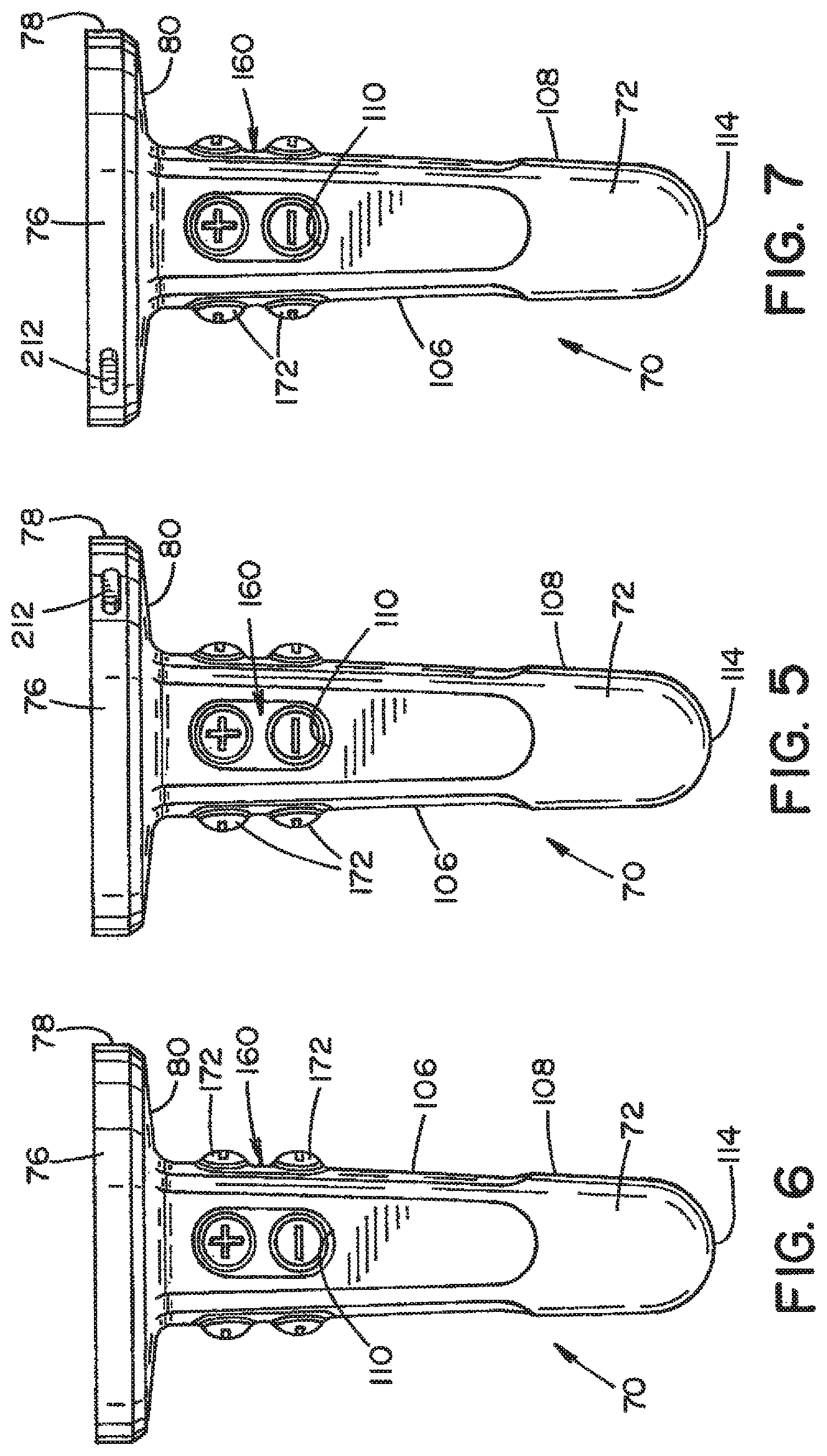
FIGS. 5-7 are side plan views of the detachable handle;
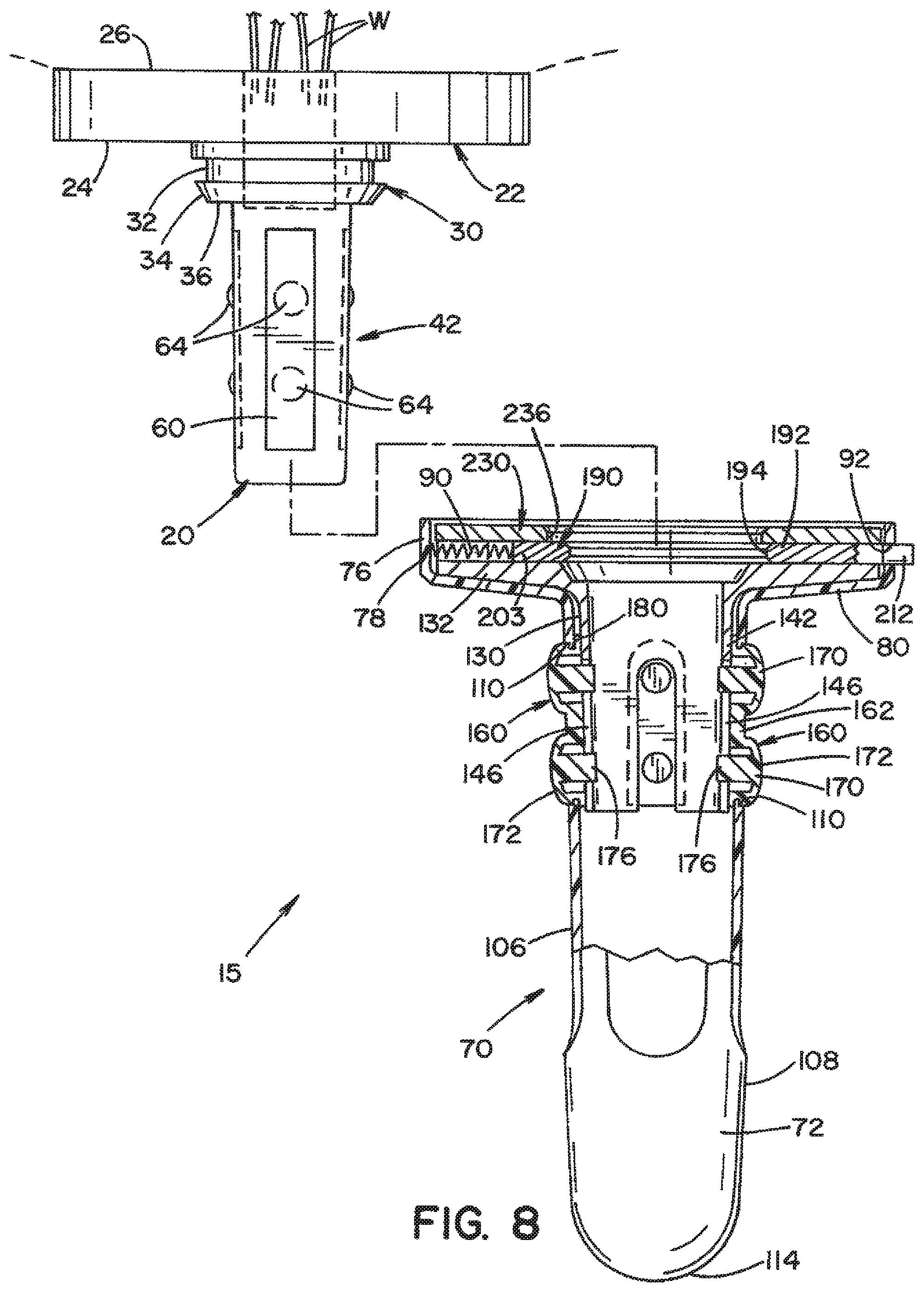
FIG. 8 is an exploded view of the handle assembly, with a partial sectional view of the detachable handle;
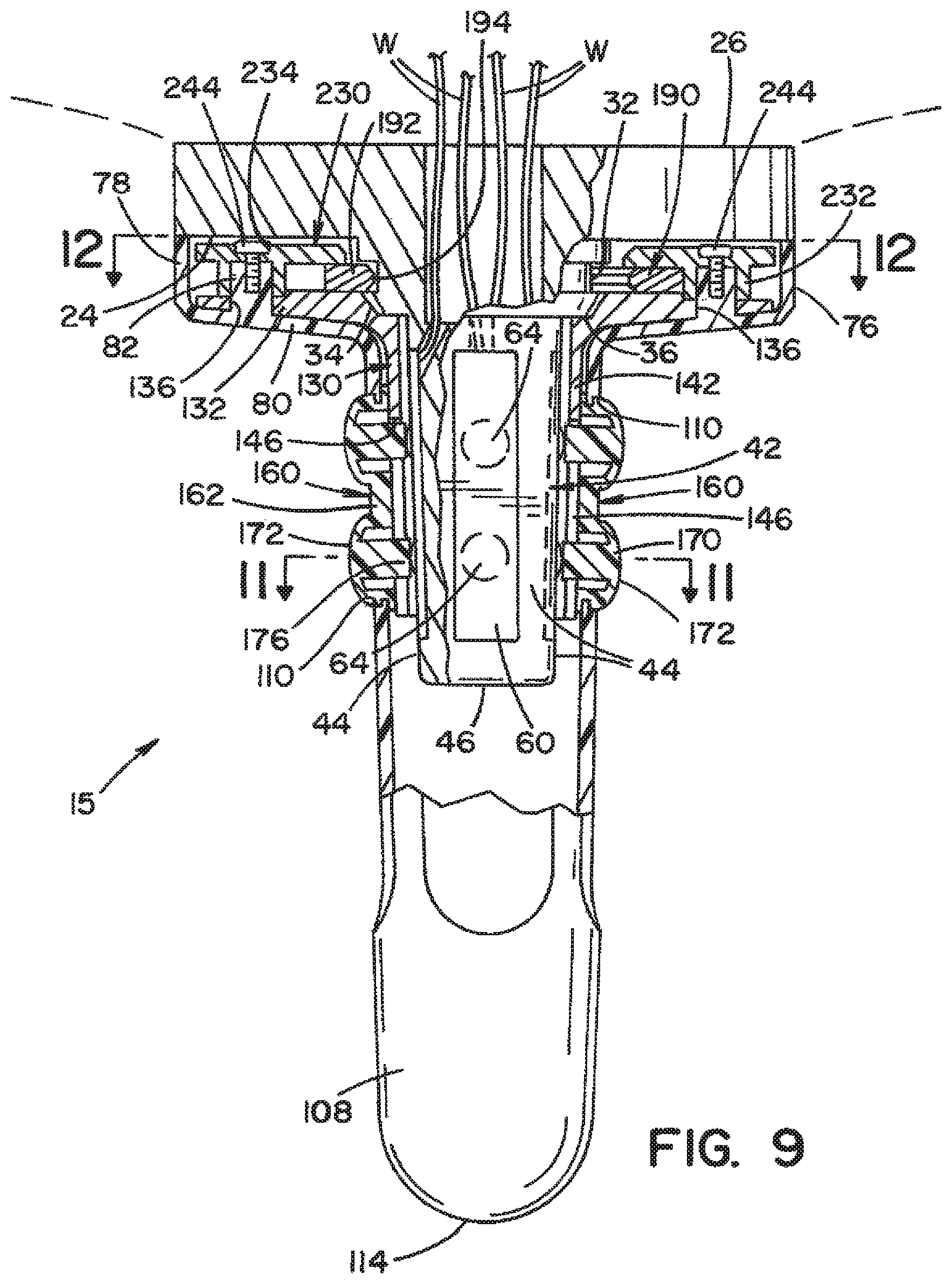
FIG. 9 is a partial sectional view of the handle assembly, with the detachable handle mounted to the base;
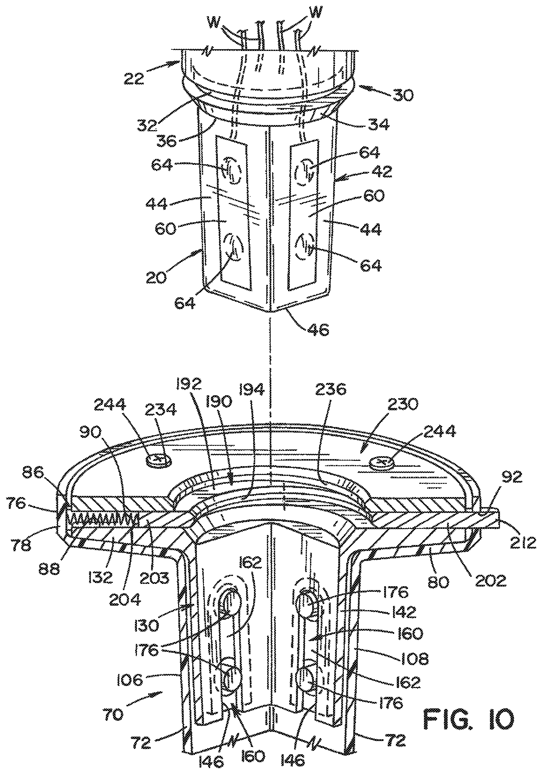
FIG. 10 is a partial exploded view of the handle assembly, with a sectional view of the detachable handle;
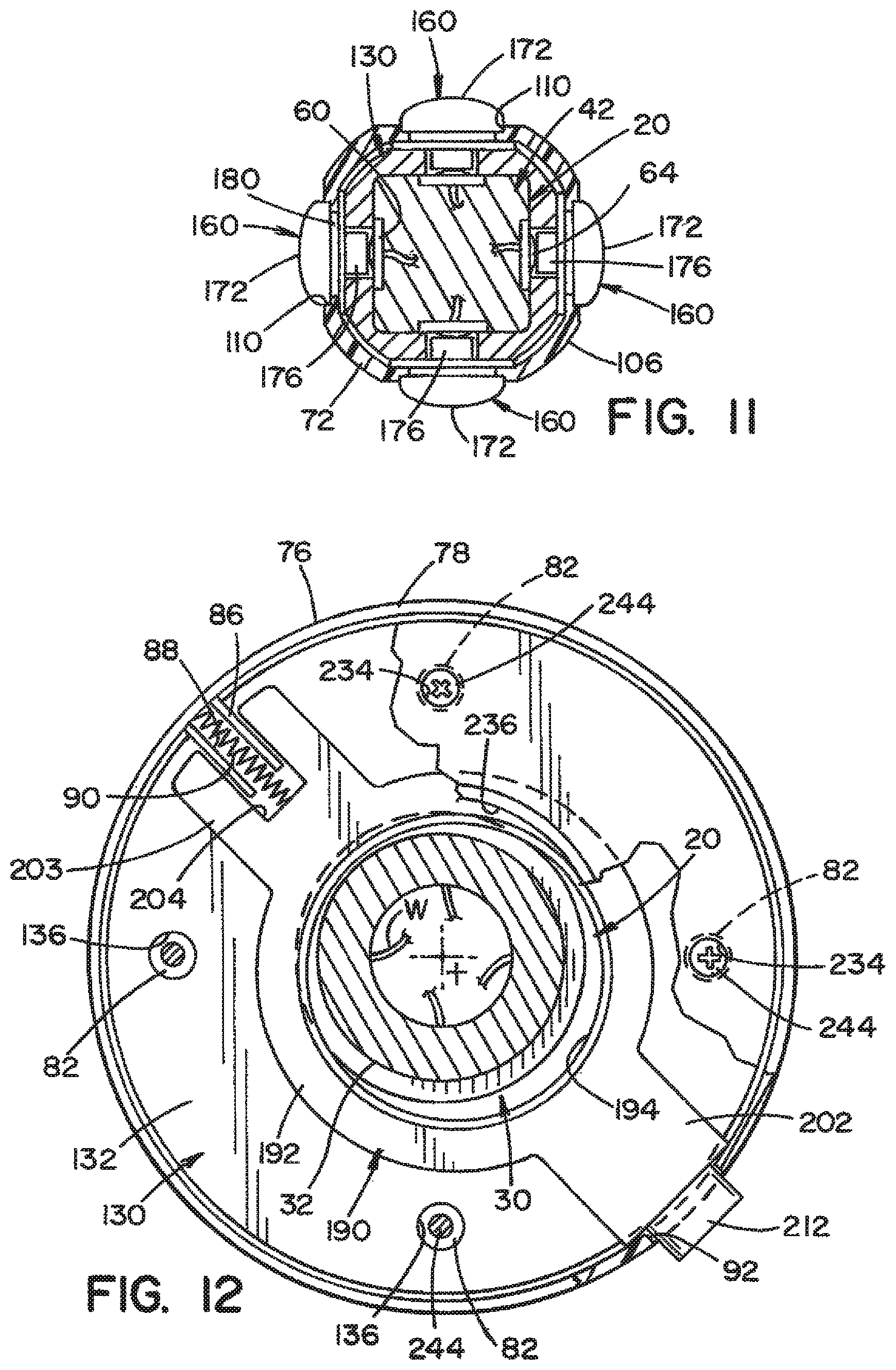
FIG. 11 is a cross-sectional view taken along lines 11-11 of FIG. 9;
FIG. 12 is a cross-sectional view taken along lines 12-12 of FIG. 9;
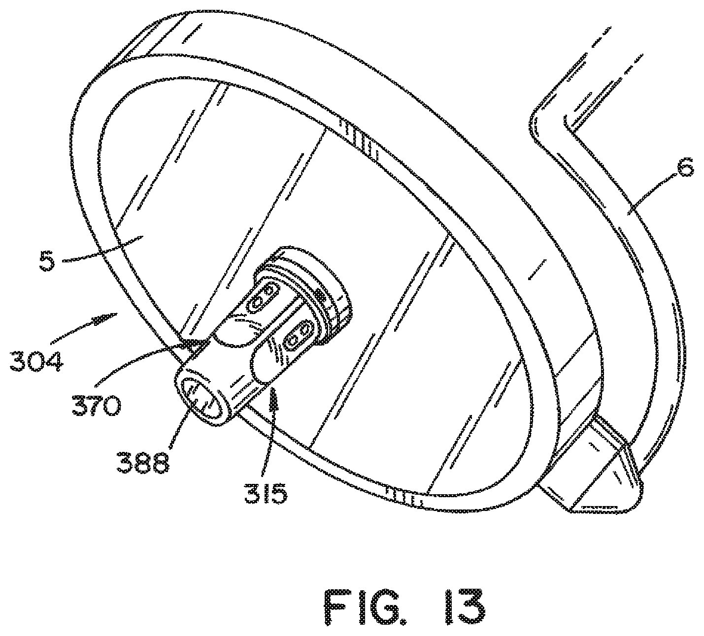
FIG. 13 is a perspective view of a lighting system including a handle assembly according to an alternative embodiment of the present invention, said handle assembly including a base and a detachable handle that also functions as a camera housing;
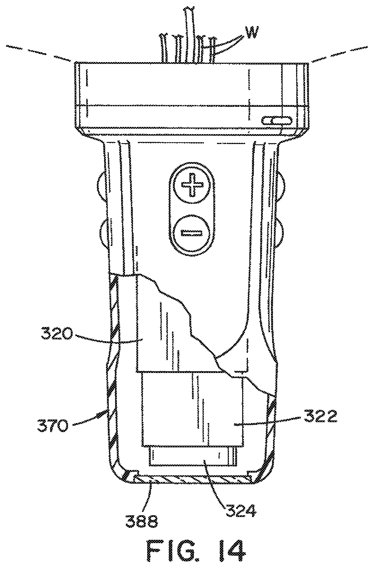
FIG. 14 shows the handle assembly of FIG. 13, with a partial sectional view of the detachable handle;
FIG. 15 is a front perspective view of a button membrane according to an alternative embodiment;
FIG. 16 is a side perspective view of the button membrane shown in FIG. 15;
FIG. 17 is a cross-sectional view of the button membrane shown in FIG. 15 as mounted to an outer housing of a detachable handle;
FIG. 18 is a front perspective view of a button assembly according to an embodiment of the present invention which includes a support frame and a button membrane according to a second alternative embodiment;
FIG. 19 is a rear perspective view of the button assembly shown in FIG. 18;
FIG. 20 is an exploded view of the button assembly shown in FIGS. 18 and 19;
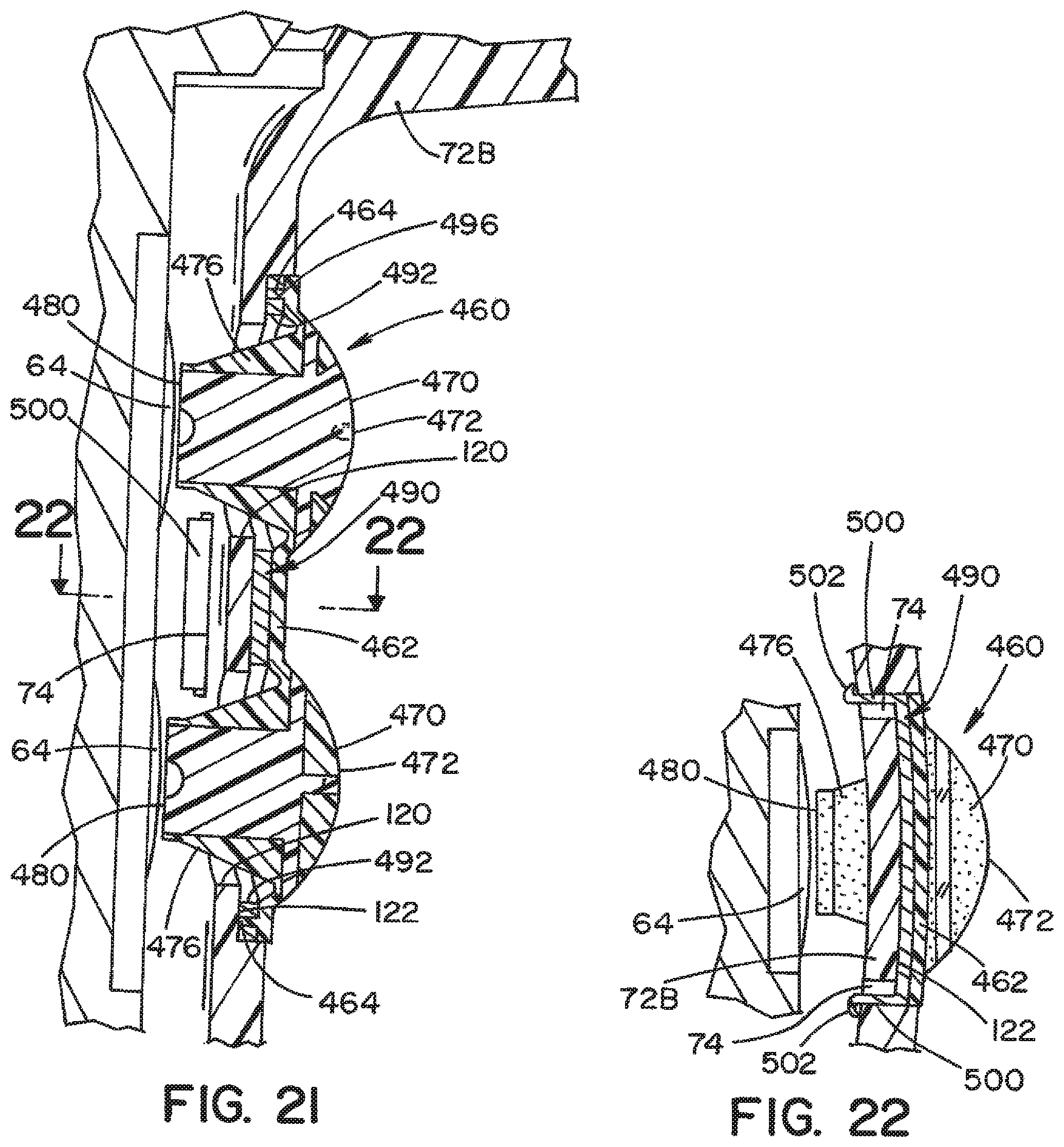
FIG. 21 is a cross-sectional view of the button assembly shown in FIGS. 18 and 19 as mounted in an outer housing of a detachable handle; and
FIG. 22 is a cross-sectional view taken along lines 22-22 of FIG. 21.
DETAILED DESCRIPTION OF THE INVENTION
Referring now to the drawings wherein the showings are for the purposes of illustrating embodiments of the invention only and not for the purposes of limiting same, FIGS. 1 and 2 show a perspective view of a portion of a lighting system 2 that includes a lighthead 4 mounted to a support member 6. Lighthead 4 is comprised of a lighting unit 5, a control unit (not shown), and a handle assembly 15 according to an embodiment of the present invention. Lighting unit 5 includes a plurality of lighting elements, such as LEDs. The control unit includes a microcontroller and associated control electronics. Handle assembly 15 is comprised of a base 20 and a detachable handle 70, which are described in detail below.
Detachable handle 70 is generally comprised of an outer housing 72 (best seen in FIGS. 3-10), an inner shell 130 (best seen in FIGS. 8-11), a plurality of button membranes 160 (best seen in FIGS. 8-11), a locking member 190 (best seen in FIGS. 8-10 and 12), and a retaining ring 230 (best seen in FIGS. 4 and 8-10).
Outer housing 72 includes a head portion 76 and a body portion 106. Head portion 76 has a side wall 78 and a bottom wall 80. Side wall 78 and bottom wall 80 define a generally cylindrical recess dimensioned to receive a portion of inner shell 130, locking member 190, and retaining ring 230, which are described in detail below. A plurality of mounting bosses 82 project from bottom wall 80, as shown in FIG. 9. Each mounting boss 82 includes an internal threaded recess dimensioned to receive a fastener 244 (e.g., a threaded screw). A locating tab 86 projects inward from side wall 78, as shown in FIG. 12. Locating tab 86 includes a channel 88 which is dimensioned to receive a bias member 90. In the illustrated embodiment, bias member 90 takes the form of a compression spring. An opening 92 is formed in side wall 78 of head portion 76, as best seen in FIGS. 10 and 12. Opening 92 is dimensioned to receive a release button 212 (of locking member 190), which extends through opening 92.
Body portion 106 of outer housing 72 includes a tubular-shaped side wall 108 and a bottom wall 114 at a distal end of outer housing 72. Openings 110 are formed in side wall 108 and are dimensioned to receive a portion of button membrane 160, as will be described below. Side wall 108 defines a recess dimensioned to receive a portion of inner shell 130, as best seen in FIGS. 8-10.
Inner shell 130 has a head portion 132 and a body portion 142, as best seen in FIGS. 8-10. In the illustrated embodiment, head portion 132 is a ring-shaped structure having a plurality of openings 136 formed therein, as shown in 9. Openings 136 are dimensioned to receive mounting bosses 82 of outer housing 72. Body portion 142 is a tubular-shaped structure having a plurality of slots 146. Slots 146 are dimensioned to receive a portion of button membrane 160, as best seen in FIGS. 8-10.
In the illustrated embodiment, each button membrane 160 has a body 162 and a plurality of button elements 170, as best seen in FIGS. 8-10. Each button element 170 includes an outward extending contact portion 172 that takes the form of a tactile raised dome-shaped button and an inward extending engagement portion 176 that takes the form of a plunger member. Contact portion 172 extends forward through opening 110 of outer housing 72, as best seen in FIG. 8. Symbols (e.g., + or - symbols) and/or a ring may be provided on contact portion 172. For instance, the translucency of contact portion 172 may be varied in different regions to provide a contrast that depicts symbols and/or a ring defining the periphery of contact portion 172. Engagement portion 176 extends through openings 110 of outer housing 72. Engagement portion 176 is dimensioned to be engageable with contact elements of base 20 when contact portion 172 is activated (i.e., depressed) by a user. A gap 180 is provided between body 162 and button elements 170 to capture an edge portion of side wall 108 of outer housing 72 adjacent to openings 110. In the illustrated embodiment, button membrane 160 is formed of silicone rubber (e.g., "80" durometer Shore A silicone) or an elastomer that is at least partially translucent. It is contemplated that a lighting element (e.g., one or more LEDs) may be located within detachable handle 70 to illuminate button membrane 160. In an embodiment of the present invention, button elements 170 may be used for user control of lighting unit 5, including, but not limited to, light intensity, ON/OFF, focus, and the like.
Locking member 190 is generally comprised of a ring section 192 having a center opening 194, and projections 202 and 203, as best seen in FIG. 12. Projection 203 includes a slot 204 dimensioned to receive locating tab 86 of outer housing 72. Bias member 90 is located within the space defined by side wall 78, locating tab 86, and projection 203. Release button 212 extends outward from projection 202. As indicated above, release button 212 extends through opening 92 of outer housing 72.
Retaining ring 230 is generally ring-shaped with a center opening 236, as best seen in FIGS. 4, 9 and 10. Retaining ring 230 includes a plurality of receptacles 232 for receiving mounting bosses 82 of outer housing 72. Each receptacle 232 includes an opening 234 dimensioned to receive fastener 244 for fixing retaining ring 230 to outer housing 72. Retaining ring 230 captures locking member 190 between retaining ring 230 and head portion 132 of inner shell 130.
According to an embodiment of the present invention, outer housing 72, inner shell 130, locking member 190 and retaining ring 230 are made of a molded plastic that is suitable for decontamination using a conventional steam sterilization process.
Base 20 of handle assembly 15 is generally comprised of a proximal section 22, a locking section 30, and a stem section 42, as best seen in FIGS. 8-12. Proximal section 22 has a front face 24 and a rear face 26, as best seen in FIG. 8. Locking section 30 includes an annular groove 32 and a frustoconical-shaped portion 34. Frustoconical-shaped portion 34 has a front face 36. Annular groove 32 is dimensioned to receive an edge portion of ring section 192 of locking member 190 located adjacent to opening 194. Detachable handle 70 is mounted to base 20 by capturing the edge portion of ring section 192 in annular groove 32. In the illustrated embodiment, stem section 42 has a plurality of side faces 44 and a front face 46. According to an embodiment of the present invention, base 20 is made of anodized aluminum. Base 20 also includes contact elements 60 that are mounted to each of the side faces 44 of base 20. Each contact element 60 has one or more tactile electrical dome switches 64 that are engaged by depressing button elements 170 of button membrane 160. Lead wires W extend from contact elements 60 through one or more channels formed in base 20 to connect with the control unit. Contact element 60 may take the form of a conventional PCB contact switching element.
It should be appreciated that detachable handle 70 may also be mechanically adapted to rotate about its axis as a means for adjusting a pattern size of the light produced by lighting unit 5.
Deferring now to FIGS. 13 and 14, an alternative embodiment of the present invention will be described. A lighthead 304 is comprised of a handle assembly 315 according to an alternative embodiment of the present invention. Handle assembly 315 has several components in common with handle assembly 15. In the illustrated embodiment, handle assembly 315 is generally comprised of a base 320 and a detachable handle 370 that also functions as a camera housing. Detachable handle 370 is substantially similar to detachable handle 70. However, a transparent window 388 is provided at the distal end of detachable handle 370. Base 320 is substantially similar to base 20. However, base 320 includes a camera comprised of an imaging unit 322 and a lens 324 at the distal end thereof.
Assembly and operation of handle assembly 15 will now be described. To mount detachable handle 70 to base 20, the longitudinal axis of detachable handle 70 is aligned with the longitudinal axis of base 20. Stem section 42 of base 20 is received within body portion 106, as best seen in FIG. 9. Detachable handle 70 is fixed to base 20 by engagement of locking member 190 with locking section 30 of base 20. Locking member 190 is movable from a locked position to an unlocked position by depressing release button 212. In the locked position, the edge portion of ring section 192 of locking member 190 is captured in annular groove 32 of locking section 30 of base 20. Bias member 90 is biased to apply a force that normally maintains locking member 190 in the locked position, as shown in FIGS. 9 and 10. When detachable handle 70 is mounted to base 20, engagement portions 176 of button membrane 160 are aligned with dome switches 64 of base 20, as best seen in FIG. 9. When a user depresses a contact portion 172 of button membrane 160, engagement portion 176 engages a dome switch 64 to activate an electronic control (e.g., light intensity). To dismount detachable handle 70 from base 20 release button 212 is depressed to move locking member 190 to the unlocked position, thereby allowing detachable handle 70 to be separated from base 20. Detachable handle 70 can then be decontaminated in a decontamination processing device, such as a steam sterilizer.
Handle assembly 315 assembles and operates in a similar manner as handle assembly 15. However, the button elements of detachable handle 370 may also be used for control of imaging unit 322. It should be appreciated that handle assemblies 15 and 315 may be interchangeably mountable to base 20.
A button membrane 260 according to an alternative embodiment will now be described with reference to FIGS. 15-16. Button membrane 260 is comprised of a body 262 and a plurality of button elements 270. Each button element 270 includes a contact portion 272 that takes the form of a tactile raised dome-shaped button, and an engagement portion 276 that takes the form of a plunger member. Engagement portion 276 has an annular flange 278 and a front face 280. Symbols (e.g., + or - symbols) and/or a ring may be provided on contact portion 272, as described above in connection with contact portion 172 of button membrane 160.
In FIG. 17 button membrane 260 is shown mounted to an outer housing 72A of a detachable handle. Outer housing 72A includes a pair of openings 120 that respectively receive a section of engagement portion 276 of button elements 270, and a recessed portion 122 for receiving a peripheral section of body 262. A portion of outer housing 72A is captured in a gap between annular flange 278 and body 262 to secure button membrane 260 to outer housing 72A. When the detachable handle is mounted to base 20, engagement portions 276 of button elements 270 are aligned with dome switches 64 of base 20. When a user depresses contact portion 272 of button element 270, engagement portion 276 moves through a travel distance to engage a dome switch 64 with front face 280, and thereby activate an electronic control (e.g., light intensity). In the illustrated embodiment, button membrane 260 is formed of silicone rubber (e.g., "80" durometer Shore A silicone) or an elastomer that is at least partially translucent. It is contemplated that a lighting element (e.g., one or more LEDs) may be located within the detachable handle to illuminate button membrane 260.
A button assembly 450 comprised of a support frame 490 and a button membrane 460 according to another alternative embodiment will now be described with reference to FIGS. 18-20. Button membrane 460 is comprised of a body 462, a plurality of protrusions 464 that retain button membrane 460 in engagement with support frame 490, and a plurality of button elements 470. In the illustrated embodiment, protrusions 464 are arc-shaped protrusions extending outward from body 462. Each button element 470 includes a contact portion 472 that takes the form of a tactile raised dome-shaped button, and an engagement portion 476 that takes the form of a plunger member. Engagement portion 476 has a front face 480. Symbols (e.g., + or - symbols) and/or a ring may be provided on contact portion 472, as described above in connection with contact portion 172 of button membrane 160.
In the illustrated embodiment, support frame 490 is comprised of a pair of openings 492 dimensioned to receive engagement portion 476 of button element 470, a plurality of slots 496 dimensioned to receive protrusions 464, and a pair of hooks or clip arms 500. Button membrane 460 may be bonded or molded to support frame 490, as shown in FIG. 19. Protrusions 464 facilitate the alignment of button membrane 460 relative to support frame 490. Support frame 490 may be formed of a rigid material, such as metal or plastic.
FIGS. 21 and 22 show button assembly 450 mounted to an outer housing 72B of a detachable handle. Inner shell 130 is omitted from these illustrations to provide greater clarity. Outer housing 72B includes a pair of openings 120 that respectively receive a section of engagement portion 476 of button elements 470, a recessed portion 122 for receiving a peripheral section of body 462, and slots 74 dimensioned to receive clip arms 500 for securing button assembly 450 to outer housing 72B. As best seen in FIG. 22, distal ends 502 of clip arms 500 engage with the inner surface of outer housing 72B to attach support frame 490 to outer housing 72B.
When a user depresses contact portion 472 of button element 470, engagement portion 476 moves through a travel distance to engage a dome switch 64 with front face 480, and thereby activate an electronic control (e.g., light intensity). In the illustrated embodiment, button membrane 460 is formed of silicone rubber (e.g., "80" durometer Shore A silicone) or an elastomer that is at least partially translucent. As noted above, it is contemplated that a lighting element (e.g., one or more LEDs) may be located within the detachable handle to illuminate button membrane 460.
The foregoing describes specific embodiments of the present invention. It should be appreciated that these embodiments are described for purposes of illustration only, and that numerous alterations and modifications may be practiced by those skilled in the art without departing from the spirit and scope of the invention. For example, it is contemplated that the detachable handle of the present invention may be adapted to incorporate additional components that are not described above, including, but not limited to, a laser, a distance sensor, etc. It is intended that all such modifications and alterations be included. Insofar as they come within the scope of the invention as claimed or the equivalents thereof.
* * * * *
D00000
D00001
D00002
D00003
D00004
D00005
D00006
D00007
D00008
D00009
D00010
D00011
D00012

D00013
XML
uspto.report is an independent third-party trademark research tool that is not affiliated, endorsed, or sponsored by the United States Patent and Trademark Office (USPTO) or any other governmental organization. The information provided by uspto.report is based on publicly available data at the time of writing and is intended for informational purposes only.
While we strive to provide accurate and up-to-date information, we do not guarantee the accuracy, completeness, reliability, or suitability of the information displayed on this site. The use of this site is at your own risk. Any reliance you place on such information is therefore strictly at your own risk.
All official trademark data, including owner information, should be verified by visiting the official USPTO website at www.uspto.gov. This site is not intended to replace professional legal advice and should not be used as a substitute for consulting with a legal professional who is knowledgeable about trademark law.