Adjustable rehabilitation and exercise device
Gomberg , et al.
U.S. patent number 10,646,746 [Application Number 16/241,167] was granted by the patent office on 2020-05-12 for adjustable rehabilitation and exercise device. This patent grant is currently assigned to ROM TECHNOLOGIES, INC.. The grantee listed for this patent is ROM3 Rehab LLC. Invention is credited to Peter Arn, Sanford Gomberg.


| United States Patent | 10,646,746 |
| Gomberg , et al. | May 12, 2020 |
Adjustable rehabilitation and exercise device
Abstract
An adjustable rehabilitation and exercise device, including a rotary member having a plurality of elongated and spaced apart elongated open-ended slots defined thereon, each slot including a plurality of enlargements along the length thereof. A mount is selectively and movably positionable on a selected one of the slots of the rotary member to select an angular location of the mount. The mount includes a slide member movably positionable along the selected slot to a selected radial location along the selected slot to select a radial location of the mount relative to the hub of the rotary member. The mount includes a movable pin having an enlarged head. The pin is positionable to selectively engage the enlarged head thereof within the enlargements of the slot so as to lock the position of the mount along the slot. A patient engagement member is connectable to the mount and movable with the mount.
| Inventors: | Gomberg; Sanford (Las Vegas, NV), Arn; Peter (Pasadena, CA) | ||||||||||
|---|---|---|---|---|---|---|---|---|---|---|---|
| Applicant: |
|
||||||||||
| Assignee: | ROM TECHNOLOGIES, INC. (Las
Vegas, NV) |
||||||||||
| Family ID: | 70612849 | ||||||||||
| Appl. No.: | 16/241,167 | ||||||||||
| Filed: | January 7, 2019 |
Related U.S. Patent Documents
| Application Number | Filing Date | Patent Number | Issue Date | ||
|---|---|---|---|---|---|
| 15700308 | Sep 11, 2017 | ||||
| 15700298 | Sep 11, 2017 | 10173095 | |||
| 15700327 | Sep 11, 2017 | 10173097 | |||
| 15700293 | Sep 11, 2017 | 10173094 | |||
| 15700287 | Sep 11, 2017 | 10226663 | |||
| 15700320 | Sep 11, 2017 | 10173096 | |||
| 62393348 | Sep 12, 2016 | ||||
| Current U.S. Class: | 1/1 |
| Current CPC Class: | A63B 21/4049 (20151001); A63B 21/00069 (20130101); A63B 22/0605 (20130101); A63B 21/015 (20130101); A63B 2225/09 (20130101) |
| Current International Class: | A63B 21/00 (20060101); A63B 22/06 (20060101); A63B 21/015 (20060101) |
References Cited [Referenced By]
U.S. Patent Documents
| 59915 | November 1866 | Lallement |
| 363522 | May 1887 | Knous |
| 446671 | February 1891 | Elliott |
| 610157 | August 1898 | Campbell |
| 631276 | August 1899 | Bullova |
| 823712 | June 1906 | Uhlmann |
| 1149029 | August 1915 | Clark |
| 1227743 | May 1917 | Burgedorff |
| 1784230 | December 1928 | Freeman |
| 3081645 | March 1963 | Bergfors |
| 3100640 | August 1963 | Weitzel |
| 3137014 | June 1964 | Meucci |
| 3143316 | August 1964 | Shapiro |
| 3713438 | January 1973 | Knutsen |
| 3744480 | July 1973 | Gause et al. |
| 3888136 | June 1975 | Lapeyre |
| 4079957 | March 1978 | Blease |
| 4408613 | October 1983 | Relyea |
| 4436097 | March 1984 | Cunningham |
| 4446753 | May 1984 | Nagano |
| 4477072 | October 1984 | DeCloux |
| 4499900 | February 1985 | Petrofsky et al. |
| 4509742 | April 1985 | Cones |
| 4606241 | August 1986 | Fredriksson |
| 4611807 | September 1986 | Castillo |
| 4648287 | March 1987 | Preskitt |
| 4673178 | June 1987 | Dwight |
| 4824104 | April 1989 | Bloch |
| 4850245 | July 1989 | Feamster et al. |
| 4858942 | August 1989 | Rodriguez |
| 4869497 | September 1989 | Stewart et al. |
| 4915374 | April 1990 | Watkins |
| 4930768 | June 1990 | Lapcevic |
| 4961570 | October 1990 | Chang |
| 5027794 | July 1991 | Pyle |
| 5161430 | November 1992 | Febey |
| 5247853 | September 1993 | Dalebout |
| D342299 | December 1993 | Birrell et al. |
| 5282748 | February 1994 | Little |
| 5316532 | May 1994 | Butler |
| 5324241 | June 1994 | Artigues et al. |
| 5336147 | August 1994 | Sweeney, III |
| 5338272 | August 1994 | Sweeney, III |
| 5361649 | November 1994 | Slocum, Jr. |
| 5458022 | October 1995 | Mattfeld et al. |
| 5487713 | January 1996 | Butler |
| 5566589 | October 1996 | Buck |
| 5580338 | December 1996 | Scelta et al. |
| 5676349 | October 1997 | Wilson |
| 5685804 | November 1997 | Whan-Tong et al. |
| 5860941 | January 1999 | Saringer et al. |
| 5950813 | September 1999 | Hoskins et al. |
| 6053847 | April 2000 | Stearns et al. |
| 6077201 | June 2000 | Cheng |
| 6102834 | August 2000 | Chen |
| 6155958 | December 2000 | Goldberg |
| 6253638 | July 2001 | Bermudez |
| 6371891 | April 2002 | Speas |
| 6430436 | August 2002 | Richter |
| 6474193 | November 2002 | Farney |
| 6543309 | April 2003 | Heim |
| 6589139 | July 2003 | Butterworth |
| 6640662 | November 2003 | Baxter |
| 6820517 | November 2004 | Farney |
| 6865969 | March 2005 | Stevens |
| 6895834 | May 2005 | Baatz |
| 7204788 | April 2007 | Andrews |
| 7226394 | June 2007 | Johnson |
| 7594879 | September 2009 | Johnson |
| 9044630 | June 2015 | Lampert et al. |
| 9312907 | April 2016 | Auchinleck et al. |
| 9480873 | November 2016 | Chuang |
| 9713744 | July 2017 | Suzuki |
| 9919198 | March 2018 | Romeo et al. |
| 10424033 | September 2019 | Romeo |
| 2003/0092536 | May 2003 | Romanelli et al. |
| 2003/0109814 | June 2003 | Rummerfield |
| 2004/0172093 | September 2004 | Rummertield |
| 2004/0194572 | October 2004 | Kim et al. |
| 2005/0015118 | January 2005 | Davis et al. |
| 2005/0020411 | January 2005 | Andrews |
| 2005/0085346 | April 2005 | Johnson |
| 2005/0085353 | April 2005 | Johnson |
| 2005/0274220 | December 2005 | Reboullet |
| 2006/0003871 | January 2006 | Houghton et al. |
| 2006/0247095 | November 2006 | Rummertield |
| 2008/0161166 | July 2008 | Lo |
| 2009/0211395 | August 2009 | Mul'e |
| 2010/0248905 | September 2010 | Lu |
| 2012/0167709 | July 2012 | Chen et al. |
| 2012/0190502 | July 2012 | Paulus et al. |
| 2013/0123071 | May 2013 | Rhea |
| 2014/0194250 | July 2014 | Reich et al. |
| 2016/0023081 | January 2016 | Popa-Simil et al. |
| 2016/0302721 | October 2016 | Wiedenhoefer et al. |
| 2017/0113092 | April 2017 | Johnson |
| 2017/0143261 | May 2017 | Wedenhoefer et al. |
| 2017/0147789 | May 2017 | Wiedenhoefer et al. |
| 2017/0181698 | June 2017 | Wiedenhoefer et al. |
| 2017/0265800 | September 2017 | Auchinleck et al. |
| 2018/0071566 | March 2018 | Gomberg et al. |
| 2018/0071569 | March 2018 | Gomberg et al. |
| 2018/0071570 | March 2018 | Gomberg et al. |
| 2018/0071571 | March 2018 | Gomberg et al. |
| 2018/0071572 | March 2018 | Gomberg et al. |
| 2018/0085615 | March 2018 | Astolfi et al. |
| 2018/0271432 | September 2018 | Auchinleck et al. |
| 2018/0280784 | October 2018 | Romeo et al. |
| 105620643 | Jun 2016 | CN | |||
| 95019 | Jul 1897 | DE | |||
| 7628633 | Dec 1977 | DE | |||
| 8519150 | Oct 1985 | DE | |||
| 3732905 | Jul 1988 | DE | |||
| 29620008 | Feb 1997 | DE | |||
| 19619820 | Jan 2001 | DE | |||
| 19947926 | Apr 2001 | DE | |||
| 0199600 | Oct 1986 | EP | |||
| 0634319 | Jan 1995 | EP | |||
| 1034817 | Sep 2000 | EP | |||
| 3264303 | Mar 2018 | EP | |||
| 2527541 | Dec 1983 | FR | |||
| 141664 | Nov 1920 | GB | |||
| 2336140 | Oct 1999 | GB | |||
| 2372459 | Aug 2002 | GB | |||
| 9809687 | Mar 1998 | WO | |||
| 2006012694 | Feb 2006 | WO | |||
Other References
|
PCT International Search Report and Written Opinion, PCT/US17/50895, dated Jan. 12, 2018; 6 pages. cited by applicant . Claris Reflex; "Better Patients Lower Costs", 2018, five pages, Claris Healthcare, Inc. Vancouver, British Columbia, Canada. cited by applicant. |
Primary Examiner: Lee; Joshua
Attorney, Agent or Firm: Dickinson Wright PLLC
Claims
The invention claimed is:
1. An adjustable rehabilitation and exercise device, comprising: a rotary member having a plurality of elongated and spaced apart elongated open-ended slots defined thereon, each slot including a plurality of enlargements along the length thereof; a mount selectively and movably positionable on a selected one of the slots of the rotary member to select an angular location of the mount, the mount including a slide member movably positionable along the selected slot to a selected radial location along the selected slot to select a radial location of the mount relative to a hub of the rotary member, the mount including a movable pin having an enlarged head, wherein the pin is positionable to selectively engage the enlarged head thereof within one of the enlargements of the slot so as to lock the position of the mount along the slot; and a patient engagement member connectable to the mount and movable with the mount.
2. The device of claim 1, wherein the enlargements are uniformly spaced along the length of the slot.
3. The device of claim 1, further comprising grooves on opposite sides of the slot parallel to the slot, with the mount including pegs slidingly disposed within the grooves.
4. The device of claim 1, wherein the slide member includes a front slide member and a rear slide member located on opposite sides of the rotary member.
Description
FIELD
This disclosure relates to the field of rehabilitation devices. More particularly, this disclosure relates to adjustable rehabilitation devices having improved connection and adjustability of patient engagement members.
BACKGROUND
Improvement is desired in the construction of adjustable rehabilitation and exercise devices. Adjustable rehabilitation and exercise devices having pedals on opposite sides and adjustably positionable relative to one another have been proposed. However, such designs require improvement due to the fact that the pedals tend to not remain securely mounted and detach, wobble and the like. In addition, it is desirable to provide for an adjustable rehabilitation or exercise device that is capable of providing both powered motion or user initiated motion without the need for separate devices.
Accordingly, in one aspect, the disclosure provides an adjustable rehabilitation and exercise device having improved structure for locating patient engagement members.
SUMMARY
The disclosure provides an adjustable rehabilitation and exercise device.
In one aspect, an adjustable rehabilitation and exercise device includes a rotary member having a plurality of elongated and spaced apart elongated open-ended slots defined thereon, each slot including a plurality of enlargements along the length thereof. A mount is selectively and movably positionable on a selected one of the slots of the rotary member to select an angular location of the mount.
The mount includes a slide member movably positionable along the selected slot to a selected radial location along the selected slot to select a radial location of the mount relative to the hub of the rotary member. The mount includes a movable pin having an enlarged head.
The pin is positionable to selectively engage the enlarged head thereof within the enlargements of the slot so as to lock the position of the mount along the slot. A patient engagement member is connectable to the mount and movable with the mount.
BRIEF DESCRIPTION OF THE DRAWINGS
Further advantages of the disclosure are apparent by reference to the detailed description when considered in conjunction with the figures, which are not to scale so as to more clearly show the details, wherein like reference numbers indicate like elements throughout the several views, and wherein:
FIGS. 1A and 1B are perspective views of an adjustable rehabilitation and exercise device according to the disclosure configured to have adjustably positionable patient engagement members.
FIGS. 2-10 show a wheel system for adjustably positioning a patient engagement member.
FIGS. 11 and 12 show an adjustable mount of the wheel system.
DETAILED DESCRIPTION
With initial reference to FIGS. 1A-1B, there is shown an adjustable rehabilitation and exercise device 10 having patient engagement members, such as pedals 12 on opposite sides that are adjustably positionable relative to one another, but securely mounted according to the disclosure to provide a more secure mounting that avoids disconnection, wobbling and the like often experienced with prior devices.
The device 10 includes a rotary device such as a wheel 14 or flywheel or the like rotatably mounted such as by a hub to a frame 16 or other support. The pedal 12 is configured for interacting with a patient to be rehabilitated and may be configured for use with lower body extremities such as the feet, legs, or upper body extremities such as the hands, arms, and the like. For example, the pedal 12 may be a conventional bicycle pedal of the type having a foot support rotatably mounted onto an axle with bearings. The axle has exposed end threads for engaging a mount on the wheel 14 to locate the pedal on the wheel 14.
The wheel 14 may be configured to have both pedals 12 on opposite sides of a single wheel. However, a preferred construction, as seen in FIGS. 1A and 1B shows a pair of the wheels 14 spaced apart from one another but interconnected to a flywheel or the like.
The rehabilitation and exercise device 10 of FIGS. 1A-1B may take the form as depicted of a traditional exercise/rehabilitation device which is more or less non-portable and remains in a fixed location, such as a rehabilitation clinic or medical practice.
Alternatively, the device 10 may be configured to be smaller and more portable unit so that it is able to be easily transported to different locations at which rehabilitation or treatment is to be provided, such as a plurality of patient's homes, alternative care facilities or the like.
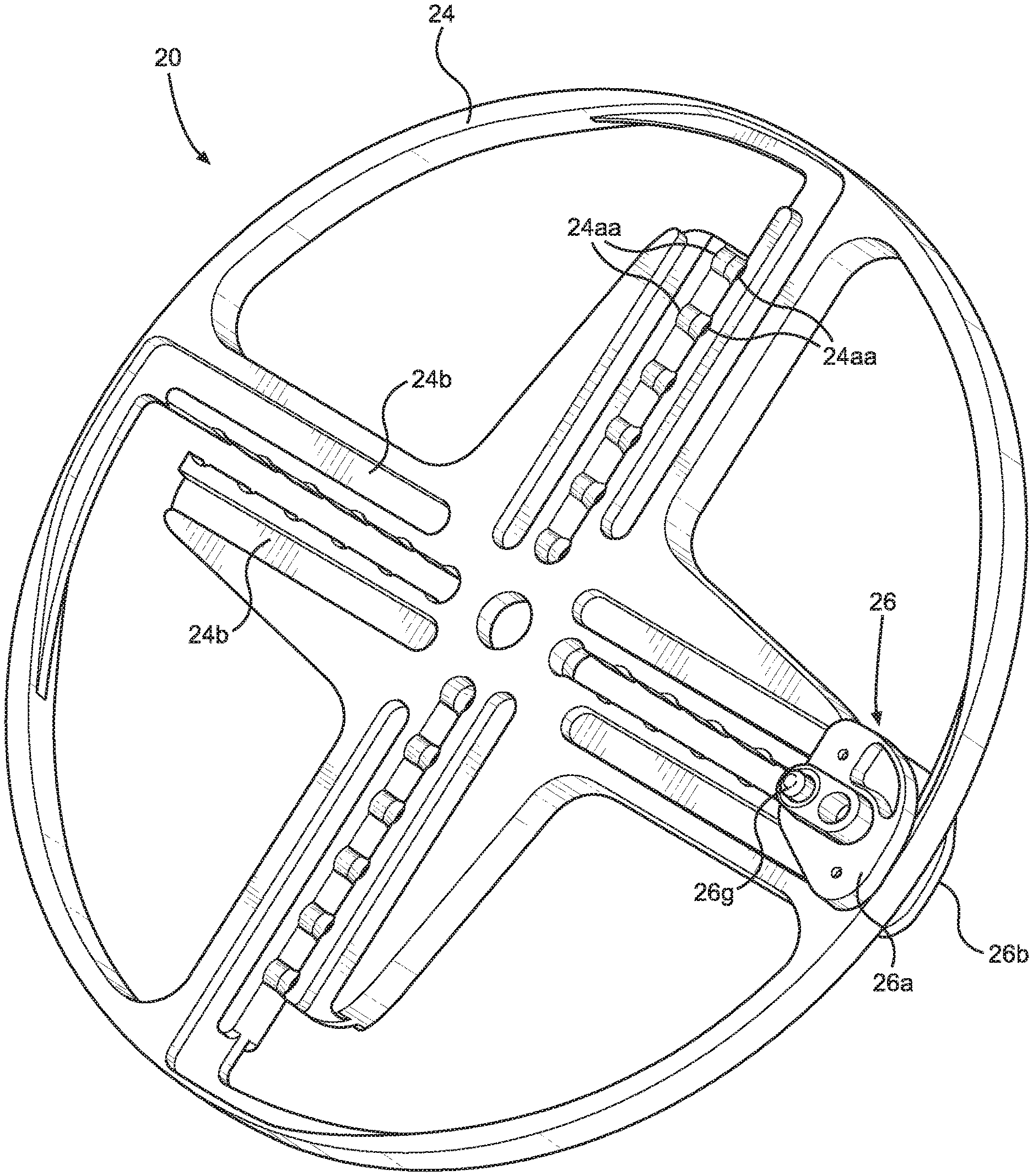
With reference to FIGS. 2-10, there is shown a wheel system 20 having a patient engagement member, such as a pedal corresponding to the pedal 12 above, adjustably mountable on a wheel 24 by an adjustable mount 26.
FIG. 2 shows a front side of the wheel 24, and FIG. 3 shows a rear side of the wheel 24. The wheel 24 is a disk configured to include a plurality of spaced apart elongated slots 24a formed through the thickness of the wheel 24 to receive the mount 26. The slots 24a include enlargements 24aa. A pair grooves 24b are formed on each side the wheel 24 parallel to and on opposite sides of the slots 24a. The wheel 24 also includes a central mounting aperture 24c to provide a hub for rotatably mounting of the wheel 24 to the device 10. Material of the wheel 24 may be removed to provide openings 24d to provide aesthetics and for reducing the weight and the cost of the wheel 24. The slots 24a and the grooves 24b desirably have open ends to facilitate installation and removal of the mount 26.
The mount 26 includes a front sliding member 26a and a rear sliding member 26b. The sliding members 26a and 26b each include pegs 26c on their inner sides for slidingly engaging he grooves 24b of the wheel 24. The sliding members 26a and 26b are fixed together as by a threaded fastener 26d that extends through a bore 26dd of the sliding member 26b and into a corresponding post 26e of the sliding member 26a (FIG. 10). The sliding member 26a includes a receiver 26f configured to receive an axle of the pedal or other patient engagement member. A lock pin 26g is provided to extend through aligned bores 26h of the sliding members 26a and 26b and pass through one of the enlargements 24aa of the slot 24a to selectively lock the position of the mount 26, as explained more fully below.
The mount 26 is slidable along the slot 24a and the grooves 24b when the lock pin 26g is not installed. The lock pin 26g is installed through the aligned bores 26h and the enlarged head 26gg is passable into the slot 24a when the head 26gg is aligned with one of the enlargements 24aa, thus seating the head 26gg in one of the enlargements 24aa, and locking the mount 26 in position. The position of the mount 26 may be adjusted by alternating the seating of the head 26gg in the various enlargements 24aa of the slot 24a. In this manner, the sliding mount 26 may be moved along the slot 24a to change its radial location on the wheel 24.
The mount 26 is configured to stably locate a pedal or other patient engagement member and eliminate wobble and the like associated with conventional devices. In addition, the mount 26 is also configured to advantageously enable substantially incremental adjustment of the position of the mount.
The mount 26 cooperates with the slot 24a and the grooves 24b to adjustably position the mount 26, and hence the pedal, relative to the hub of the wheel 24. Further, the availability of a plurality of slots 24a enables a user to select which slot 24a for installation of the mount 26. Thus, in combination, the mount 26 and the slots 24a with their respective grooves 24b enable radial and angular adjustment of the position of the pedal or other patient engagement member. When this manner of adjustment is used for both of the pedals on opposite sides of the device 10, it will be appreciated that the pedals, or other patient engagement members, may be adjustably positioned relative to one another angularly, with each pedal being radially adjustable relative to the hubs of the wheels.
The foregoing description of preferred embodiments for this disclosure has been presented for purposes of illustration and description. It is not intended to be exhaustive or to limit the disclosure to the precise form disclosed. Obvious modifications or variations are possible in light of the above teachings. The embodiments are chosen and described in an effort to provide the best illustrations of the principles of the disclosure and its practical application, and to thereby enable one of ordinary skill in the art to utilize the disclosure in various embodiments and with various modifications as are suited to the particular use contemplated. All such modifications and variations are within the scope of the disclosure
* * * * *
D00000
D00001
D00002
D00003
D00004
D00005
D00006
D00007
D00008
D00009
D00010
XML
uspto.report is an independent third-party trademark research tool that is not affiliated, endorsed, or sponsored by the United States Patent and Trademark Office (USPTO) or any other governmental organization. The information provided by uspto.report is based on publicly available data at the time of writing and is intended for informational purposes only.
While we strive to provide accurate and up-to-date information, we do not guarantee the accuracy, completeness, reliability, or suitability of the information displayed on this site. The use of this site is at your own risk. Any reliance you place on such information is therefore strictly at your own risk.
All official trademark data, including owner information, should be verified by visiting the official USPTO website at www.uspto.gov. This site is not intended to replace professional legal advice and should not be used as a substitute for consulting with a legal professional who is knowledgeable about trademark law.