MEMS microphone
Zhang , et al.
U.S. patent number 10,645,499 [Application Number 16/234,791] was granted by the patent office on 2020-05-05 for mems microphone. This patent grant is currently assigned to AAC Acoustic Technologies (Shenzhen) Co., Ltd.. The grantee listed for this patent is AAC ACOUSTIC TECHNOLOGIES (SHENZHEN) CO., LTD. Invention is credited to Ting Kang, Jinyu Zhang, Rui Zhang.


| United States Patent | 10,645,499 |
| Zhang , et al. | May 5, 2020 |
MEMS microphone
Abstract
An MEMS microphone, including a base having a back cavity, and a capacitor system fixedly supported on the base, the capacitor system including a diaphragm and a back-plate spaced from the diaphragm. The diaphragm is provided with a venting portion passing through an edge thereof, and the base includes an inner side surface surrounding the back cavity and at least one venting groove formed by recessing from an inner side surface in a direction away from the back cavity direction. The at least one venting groove is disposed corresponding to the venting portion and is in communication with the venting portion and the back cavity, respectively. The base is provided with a venting groove, so that the back cavity has larger space for venting, and the airflow can easily pass through, thereby reducing the probability of breaking the diaphragm. Thus, the MEMS microphone can have a higher reliability.
| Inventors: | Zhang; Rui (Shenzhen, CN), Zhang; Jinyu (Shenzhen, CN), Kang; Ting (Shenzhen, CN) | ||||||||||
|---|---|---|---|---|---|---|---|---|---|---|---|
| Applicant: |
|
||||||||||
| Assignee: | AAC Acoustic Technologies
(Shenzhen) Co., Ltd. (ShenZhen, CN) |
||||||||||
| Family ID: | 63563396 | ||||||||||
| Appl. No.: | 16/234,791 | ||||||||||
| Filed: | December 28, 2018 |
Prior Publication Data
| Document Identifier | Publication Date | |
|---|---|---|
| US 20190246215 A1 | Aug 8, 2019 | |
Foreign Application Priority Data
| Feb 6, 2018 [CN] | 2018 2 0213684 U | |||
| Current U.S. Class: | 1/1 |
| Current CPC Class: | H04R 1/04 (20130101); B81B 7/0061 (20130101); H04R 19/005 (20130101); H04R 19/04 (20130101); H04R 1/222 (20130101); B81B 2203/0127 (20130101); H04R 2201/003 (20130101); B81B 2201/0257 (20130101) |
| Current International Class: | H04R 19/04 (20060101); B81B 7/00 (20060101); H04R 1/04 (20060101); H04R 19/00 (20060101); H04R 1/22 (20060101) |
References Cited [Referenced By]
U.S. Patent Documents
| 4776019 | October 1988 | Miyatake |
| 5677965 | October 1997 | Moret |
| 7885423 | February 2011 | Weigold |
| 8104354 | January 2012 | Hsu |
| 10266393 | April 2019 | Chung |
| 2006/0210106 | September 2006 | Pedersen |
| 2008/0123876 | May 2008 | Sato |
| 2008/0181437 | July 2008 | Suzuki |
| 2013/0161702 | June 2013 | Chen |
| 2014/0247954 | September 2014 | Hall |
Attorney, Agent or Firm: IPro, PLLC Xu; Na
Claims
What is claimed is:
1. A micro-electro-mechanical system (MEMS) microphone, comprising: a base having a back cavity; and a capacitor system fixedly supported on the base, the capacitor system comprising a diaphragm and a back-plate spaced apart from the diaphragm, wherein the diaphragm is provided with a venting portion penetrating through an edge thereof, the base comprises an inner side surface enclosing the back cavity and at least one venting groove recessed from the inner side surface in a direction facing away from the back cavity, the at least one venting groove and the venting portion are disposed correspondingly to each other and the at least one venting groove is in communication with the venting portion and the back cavity, respectively; wherein the diaphragm comprises a body portion located in the back cavity and a plurality of extensions extending from the body portion toward the back-plate, the plurality of extensions is spaced apart from one another, and the diaphragm is fixed to the base by the plurality of extensions; wherein the base further comprises at least one recess recessed from the inner side surface toward the direction facing away from the back cavity, the at least one recess and the plurality of extensions are disposed correspondingly to each other and used to provide space for the plurality of extensions during vibration.
2. The MEMS microphone according to claim 1, wherein the venting portion is formed between adjacent ones of the plurality of extensions.
3. The MEMS microphone according to claim 2, wherein four extensions are provided, and the four extensions are equidistantly spaced from one another.
4. The MEMS microphone according to claim 3, wherein the body portion has a rectangular shape, and each of the four extensions extends outward from a corner of the body portion.
5. The MEMS microphone according to claim 4, wherein the inner side surface has a rectangular cross-section in a direction perpendicular to a vibration direction of the diaphragm, and the at least one recess is located at a corner of the inner side surface.
Description
CROSS-REFERENCE TO RELATED APPLICATIONS
The present application claims priority to Chinese Patent Application No. 201820213684.7, filed on Feb. 6, 2018, the content of which is incorporated herein by reference in its entirety.
TECHNICAL FIELD
The present disclosure relates to the field of electroacoustic conversion, and in particular, to a MEMS microphone.
BACKGROUND
In recent years, mobile communication technologies have been rapidly developed, and consumers are increasingly using mobile communication devices, such as portable phones, portable phones with Internet access, personal digital assistants, or other devices that communicate with a dedicated communication network, among which a microphone is an important component, especially a MEMS microphone.
A Micro-Electro-Mechanical System (MEMS) microphone is an electroacoustic transducer manufactured by micro-machining technology, which has the characteristics of small volume, good frequency response and low noise. With the development of small and light electronic devices, MEMS microphones are increasingly applied in these devices.
A MEMS microphone in the related art includes a base having a back cavity, a diaphragm and a back-plate fixedly supported on the base. The diaphragm and the back-plate are disposed opposite to and spaced from each other to form a capacitor structure. The diaphragm is provided with a venting portion at an edge region thereof, and when the diaphragm encounters a large airflow, the diaphragm moves and the airflow portion allows the airflow to quickly pass through the diaphragm, thereby reducing the probability of diaphragm breaking.
However, in the related art, when the airflow encountered by the diaphragm has a direction from a side of the diaphragm facing away from the back cavity toward the back cavity, the diaphragm moves toward the back cavity, and a narrow gas path in the back cavity causes poor air leakage due to limitation of the base, and thus it is easy to cause the diaphragm to break.
Therefore, it is necessary to provide an improved MEMS microphone to solve the above problems.
BRIEF DESCRIPTION OF DRAWINGS
In order to illustrate technical solutions in embodiments of the present disclosure, the accompanying drawings used in the embodiments are introduced as follows. It should be noted that the drawings described as follows are merely part of the embodiments of the present disclosure, other drawings can also be acquired by those skilled in the art without paying creative efforts.
FIG. 1 is a schematic view of an overall structure of an MEMS microphone according to an embodiment of the present disclosure;
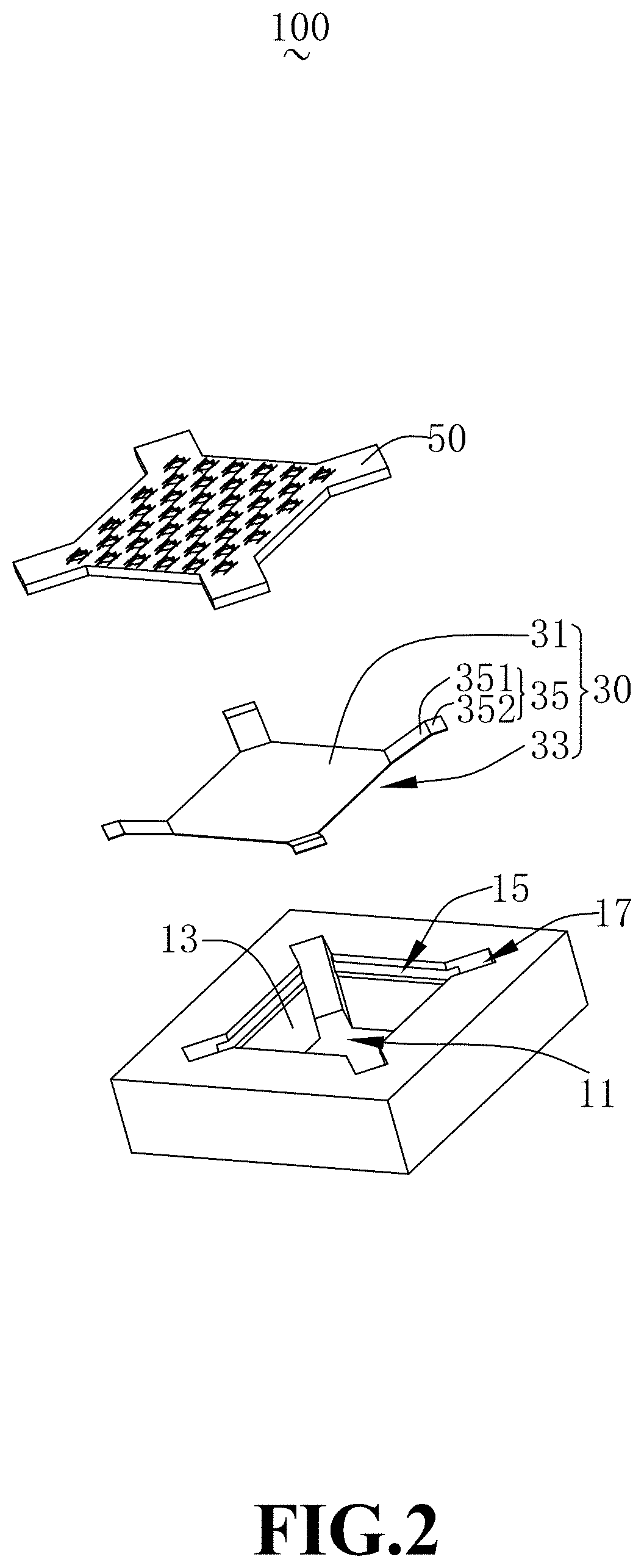
FIG. 2 is a schematic exploded view of an MEMS microphone according to an embodiment of the present disclosure;
FIG. 3 is a cross-sectional view taken along line A-A of FIG. 1; and
FIG. 4 is a cross-sectional view taken along line B-B of FIG. 1.
DESCRIPTION OF EMBODIMENTS
In order to make the purpose, technical solutions, and advantages of the embodiments of the present disclosure to be understandable, the technical solutions in the embodiments of the present disclosure are described in the following with reference to the accompanying drawings. It should be understood that the described embodiments are merely exemplary embodiments of the present disclosure, which shall not be interpreted as providing limitations to the present disclosure. All other embodiments obtained by those skilled in the art without creative efforts according to the embodiments of the present disclosure are within the scope of the present disclosure.
FIG. 1 is a schematic view of an overall structure of an MEMS microphone according to an embodiment of the present disclosure, and FIG. 2 is a schematic exploded view of an MEMS microphone according to an embodiment of the present disclosure. With reference to FIG. 1 and FIG. 2, the present disclosure provides an MEMS microphone 100 including a base 10 having a back cavity 11, and a capacitor system 40 fixedly supported on the base 10. Herein, the capacitor system 40 includes a diaphragm 30 and a back-plate 50 spaced apart from the diaphragm.
The base 10 is made of a semiconductor material, such as silicon.
FIG. 3 is a cross-sectional view taken along line A-A of FIG. 1, and FIG. 4 is a cross-sectional view taken along line B-B of FIG. 1. With reference to FIG. 3 and FIG. 4, the base 10 includes a back cavity 11, an inner side surface 13 enclosing to form the back cavity 11, and a venting groove 15 and a recess 17 formed recessing from the inner side surface 13 in a direction facing away from the back cavity 11. The venting groove 15 is arranged between adjacent recesses 17.
The back cavity 11 penetrates through the base 10.
In one embodiment, the back cavity 11 may be formed by a bulk-silicon micromachining process or etching.
The diaphragm 30 includes a body portion 31 shaped as a rectangle, and a plurality of extensions 35 extending from corners of the body portion 31 toward the back-plate 50. The plurality of extensions 35 is spaced apart from one another. The diaphragm 30 is fixed to the base 10 by the extensions 35. Optionally, four extensions 35 are provided. The venting portion 33 is formed between adjacent extensions 35.
The venting groove 15 of the base 10 is disposed corresponding to the venting portion 33 of the diaphragm 30, and is in communication with the venting portion 33 and the back cavity 11, respectively.
When the body portion 31 moves toward the back cavity 11 under a force, an orthographic projection of the body portion 31 in the direction perpendicular to the vibration direction toward the venting groove 15 is at least partially located in the venting groove 15, that is, when the body portion 31 moves toward the back cavity 11 under a force, the venting portion 33 is in communication with the venting groove 15.
The venting portion 33 is used for circulation of the airflow to prevent the diaphragm from breaking.
The extension 35 includes a first portion 351 extending from the body portion 31, and a second portion 352 extending from the first portion 351.
The second portion 352 is fixed to the base 10, and the diaphragm 30 is thereby fixed to the base 10.
When a side of the diaphragm 30 close to the back cavity 11 encounters a strong airflow, the diaphragm 30 moves in a direction facing away from the back cavity 11. Since outer space of the back cavity 11 is open and unobstructed, the airflow can quickly pass through the periphery of the diaphragm 30, and the probability of breaking the diaphragm 30 is small.
When a side of the diaphragm 30 facing away from the back cavity 11 encounters a strong airflow, the diaphragm 30 moves toward the interior of the back cavity 11. Since the venting groove 15 increases a volume of the back cavity 11, the airflow can pass through more easily. The airflow passes through the venting portion 31 and then flows to the venting groove 15 having a larger space. Then the airflow flows out from the back cavity 11 after the resistance is reduced by the venting groove 15. In this way, the force of the airflow applied on the diaphragm 30 is reduced, thereby reducing the probability of breaking the diaphragm 30.
The inner side surface 13 is enclosed as a rectangular structure, that is, the cross-section of the inner side surface 13 in a direction perpendicular to the vibration direction of the diaphragm has a rectangular shape. The recess 17 is located at a corner of the inner side surface 13 and is disposed corresponding to the extension 35 of the diaphragm 30. Therefore, during vibration of the diaphragm 30, the recess 17 can provide space to the extension 35.
Four venting grooves 15 are provided in this embodiment, and distributed in a rectangular array. In other embodiments, the venting groove 15 may have an arc-shaped structure, and a plurality of venting grooves 15 may be provided and spaced from one other and distributed in an annular array.
Four recesses 17 are provided and formed at four corners of the side wall 13, and the recesses 17 are in communication with the venting grooves 15.
Compared with the related art, the MEMS microphone 100 in embodiments of the present disclosure has following beneficial effects. When a side of the diaphragm 30 facing away from the back cavity 11 encounters a strong airflow and the diaphragm 30 therefore moves toward back cavity 11, the venting groove 15 can allow the back cavity 11 to be increased in volume, and the airflow can pass through more easily. The airflow passes through the venting portion 31 and then flows to the venting groove 15 having a larger space. Then the airflow flows out from the back cavity 11 after the resistance is reduced by the venting groove 15. In this way, the impact duration of the airflow applied on the diaphragm 30 is reduced, thereby reducing the probability of breaking the diaphragm 30. When a side of the diaphragm 30 close to the back cavity 11 encounters a strong airflow and therefore the diaphragm 30 moves in a direction facing away from the back cavity 11, since outer space in this direction is open and unobstructed, the airflow can pass through quickly, and the probability of breaking the diaphragm 30 is small. Thus, the structure described above can improve reliability of the MEMS microphone 100.
It should be noted that, the described embodiments are merely exemplary embodiments of the present disclosure, which shall not be interpreted as providing limitations to the present disclosure. All other embodiments obtained by those skilled in the art without creative efforts according to the embodiments of the present disclosure are within the scope of the present disclosure.
* * * * *
D00000
D00001
D00002
D00003
D00004
XML
uspto.report is an independent third-party trademark research tool that is not affiliated, endorsed, or sponsored by the United States Patent and Trademark Office (USPTO) or any other governmental organization. The information provided by uspto.report is based on publicly available data at the time of writing and is intended for informational purposes only.
While we strive to provide accurate and up-to-date information, we do not guarantee the accuracy, completeness, reliability, or suitability of the information displayed on this site. The use of this site is at your own risk. Any reliance you place on such information is therefore strictly at your own risk.
All official trademark data, including owner information, should be verified by visiting the official USPTO website at www.uspto.gov. This site is not intended to replace professional legal advice and should not be used as a substitute for consulting with a legal professional who is knowledgeable about trademark law.