Video analytic rule detection system and method
Titus , et al.
U.S. patent number 10,645,350 [Application Number 14/058,423] was granted by the patent office on 2020-05-05 for video analytic rule detection system and method. This patent grant is currently assigned to AVIGILON FORTRESS CORPORATION. The grantee listed for this patent is AVIGILON FORTRESS CORPORATION. Invention is credited to John I. W. Clark, Alan J. Lipton, Kelly Schomburg, Steve Titus, Peter L. Venetianer, Li Yu, Zhong Zhang.


View All Diagrams
| United States Patent | 10,645,350 |
| Titus , et al. | May 5, 2020 |
Video analytic rule detection system and method
Abstract
A video surveillance system is set up, calibrated, tasked, and operated. The system extracts video primitives and extracts even occurrences from the video primitives using event discriminators. The extracted video primitives and event occurrences may be used to create and define additional video analytic rules. The system can undertake a response, such as an alarm, based on extracted event occurrences.
| Inventors: | Titus; Steve (Herndon, VA), Zhang; Zhong (Great Falls, VA), Clark; John I. W. (Flamborough, CA), Lipton; Alan J. (Austin, TX), Schomburg; Kelly (Reston, VA), Venetianer; Peter L. (McLean, VA), Yu; Li (Sterling, VA) | ||||||||||
|---|---|---|---|---|---|---|---|---|---|---|---|
| Applicant: |
|
||||||||||
| Assignee: | AVIGILON FORTRESS CORPORATION
(Vancouver, British Columbia, CA) |
||||||||||
| Family ID: | 40304645 | ||||||||||
| Appl. No.: | 14/058,423 | ||||||||||
| Filed: | October 21, 2013 |
Prior Publication Data
| Document Identifier | Publication Date | |
|---|---|---|
| US 20140293048 A1 | Oct 2, 2014 | |
Related U.S. Patent Documents
| Application Number | Filing Date | Patent Number | Issue Date | ||
|---|---|---|---|---|---|
| 11828842 | Jul 26, 2007 | 8564661 | |||
| 11167218 | Jun 28, 2005 | 9892606 | |||
| 11098385 | Apr 5, 2005 | 7868912 | |||
| 11057154 | Feb 15, 2005 | ||||
| 09987707 | Nov 15, 2001 | ||||
| 09694712 | Oct 24, 2000 | 6954498 | |||
| 14058423 | |||||
| 11828842 | Jul 26, 2007 | 8564661 | |||
| 11057154 | Feb 15, 2005 | ||||
| 09987707 | Nov 15, 2001 | ||||
| 09694712 | Oct 24, 2000 | 6954498 | |||
| Current U.S. Class: | 1/1 |
| Current CPC Class: | H04N 7/188 (20130101); G08B 13/19656 (20130101); G08B 13/19613 (20130101); G08B 13/19608 (20130101); G06K 9/00771 (20130101); G08B 13/19652 (20130101); G07C 9/00 (20130101) |
| Current International Class: | H04N 7/18 (20060101); G08B 13/196 (20060101); G06K 9/00 (20060101); G07C 9/00 (20200101) |
| Field of Search: | ;348/143 |
References Cited [Referenced By]
U.S. Patent Documents
| 3812278 | May 1974 | Aker |
| 3812287 | May 1974 | Lemelson |
| 3988533 | October 1976 | Mick et al. |
| 4160998 | July 1979 | Kamin |
| 4198653 | April 1980 | Kamin |
| 4249207 | February 1981 | Harman et al. |
| 4257063 | March 1981 | Loughry et al. |
| 4458266 | July 1984 | Mahoney |
| 4539590 | September 1985 | Gage |
| 4593274 | June 1986 | Rizzo |
| 4737847 | April 1988 | Araki |
| 4764971 | August 1988 | Sullivan |
| 4857912 | August 1989 | Everett et al. |
| 4908704 | March 1990 | Fujioka et al. |
| 4941182 | July 1990 | Patel |
| 4943854 | July 1990 | Shiota et al. |
| 4949389 | August 1990 | Allebach et al. |
| 5048095 | September 1991 | Bhanu et al. |
| 5091780 | February 1992 | Pomerlau |
| 5099322 | March 1992 | Gove |
| 5099324 | March 1992 | Abe |
| 5159647 | October 1992 | Burt |
| 5161107 | November 1992 | Mayeaux et al. |
| 5164827 | November 1992 | Paff |
| 5229850 | July 1993 | Toyoshima |
| 5243418 | September 1993 | Kuno |
| 5296852 | June 1994 | Rathi |
| 5321396 | June 1994 | Lamming et al. |
| 5448315 | September 1995 | Soohoo |
| 5448651 | September 1995 | Sakou et al. |
| 5465115 | November 1995 | Conrad et al. |
| 5485611 | January 1996 | Astle |
| 5491511 | February 1996 | Odle |
| 5515453 | May 1996 | Hennessey et al. |
| 5519789 | May 1996 | Etoh |
| 5521634 | May 1996 | McGary |
| 5526133 | June 1996 | Paff |
| 5576972 | November 1996 | Harrison |
| 5586200 | December 1996 | Devaney et al. |
| 5602585 | February 1997 | Dickinson |
| 5610653 | March 1997 | Abecassis |
| 5621889 | April 1997 | Lermuzeaux et al. |
| 5623249 | April 1997 | Camire |
| 5666157 | September 1997 | Aviv |
| 5671294 | September 1997 | Rogers |
| 5684715 | November 1997 | Palmer |
| 5696503 | December 1997 | Nasburg |
| 5696551 | December 1997 | Katto |
| 5708767 | January 1998 | Yeo et al. |
| 5721692 | February 1998 | Nagaya et al. |
| 5724456 | March 1998 | Boyack et al. |
| 5751346 | May 1998 | Dozier et al. |
| 5764306 | June 1998 | Steffano |
| 5768413 | June 1998 | Levin |
| 5774569 | June 1998 | Waldenmaier |
| 5798787 | August 1998 | Yamaguchi et al. |
| 5801943 | September 1998 | Nasburg |
| 5802203 | September 1998 | Black et al. |
| 5802361 | September 1998 | Wang et al. |
| 5809161 | September 1998 | Auty et al. |
| 5812193 | September 1998 | Tomitaka et al. |
| 5844603 | December 1998 | Ogata |
| 5850352 | December 1998 | Moezzi et al. |
| 5860086 | January 1999 | Crump et al. |
| 5872865 | February 1999 | Normile et al. |
| 5875304 | February 1999 | Winter et al. |
| 5875305 | February 1999 | Winter et al. |
| 5886701 | March 1999 | Chauvin et al. |
| 5912980 | June 1999 | Hunke |
| 5923365 | July 1999 | Tamir et al. |
| 5926210 | July 1999 | Hackett et al. |
| 5937092 | August 1999 | Wootton et al. |
| 5956081 | September 1999 | Katz et al. |
| 5959690 | September 1999 | Toebes, VIII et al. |
| 5963202 | October 1999 | Polish |
| 5963203 | October 1999 | Goldberg et al. |
| 5969755 | October 1999 | Courtney |
| 5974235 | October 1999 | Nunally |
| 5983147 | November 1999 | Krumm |
| 5983251 | November 1999 | Martens et al. |
| 5987211 | November 1999 | Abecassis |
| 5990955 | November 1999 | Koz |
| 5999189 | December 1999 | Kajiya et al. |
| 5999877 | December 1999 | Takahasi et al. |
| 6008865 | December 1999 | Fogel |
| 6014461 | January 2000 | Hennessey et al. |
| 6025877 | February 2000 | Chang et al. |
| 6028626 | February 2000 | Aviv |
| 6031573 | February 2000 | MacCormack et al. |
| 6035341 | March 2000 | Nunally |
| 6044166 | March 2000 | Bassman et al. |
| 6049363 | April 2000 | Courtney et al. |
| 6058210 | May 2000 | Dequeiroz et al. |
| 6067112 | May 2000 | Wellner et al. |
| 6069653 | May 2000 | Hudson |
| 6069655 | May 2000 | Seeley et al. |
| 6069918 | May 2000 | Meyer |
| 6075560 | June 2000 | Katz |
| 6078619 | June 2000 | Monro |
| 6084912 | July 2000 | Reitmier et al. |
| 6088484 | July 2000 | Mead |
| 6091771 | July 2000 | Seeley et al. |
| 6091846 | July 2000 | Lin et al. |
| 6097429 | August 2000 | Seeley et al. |
| 6108033 | August 2000 | Ito et al. |
| 6123123 | September 2000 | Carder et al. |
| 6128396 | October 2000 | Hasegawa |
| 6128398 | October 2000 | Kuperstein et al. |
| 6144375 | November 2000 | Jain et al. |
| 6151413 | November 2000 | Jang et al. |
| 6166744 | December 2000 | Jaszlics et al. |
| 6167143 | December 2000 | Badique |
| 6177886 | January 2001 | Billington et al. |
| 6182022 | January 2001 | Mayle et al. |
| 6187777 | February 2001 | Darrell et al. |
| 6188381 | February 2001 | Siemen van der Wal et al. |
| 6188777 | February 2001 | Darrell et al. |
| 6195458 | February 2001 | Warnick et al. |
| 6201473 | March 2001 | Schaffer |
| 6201476 | March 2001 | Depeursinge et al. |
| 6205239 | March 2001 | Lin et al. |
| 6211907 | April 2001 | Scaman et al. |
| 6226388 | May 2001 | Qian et al. |
| 6249613 | June 2001 | Crinon et al. |
| 6253064 | June 2001 | Monroe |
| 6271752 | August 2001 | Vaios |
| 6278466 | August 2001 | Chen |
| 6295367 | September 2001 | Crabtree et al. |
| 6297844 | October 2001 | Schatz et al. |
| 6304669 | October 2001 | Kaneko et al. |
| 6307885 | October 2001 | Moon et al. |
| 6310916 | October 2001 | Han et al. |
| 6326964 | December 2001 | Snyder et al. |
| 6337917 | January 2002 | Onural et al. |
| 6411724 | January 2002 | Vaithilingham et al. |
| 6349113 | February 2002 | Mech et al. |
| 6351265 | February 2002 | Bulman |
| 6351492 | February 2002 | Kim et al. |
| 6360234 | March 2002 | Jain et al. |
| 6385772 | May 2002 | Courtney |
| 6393054 | May 2002 | Altunbasak et al. |
| 6393056 | May 2002 | Talluri |
| 6396535 | May 2002 | Waters |
| 6396876 | May 2002 | Babonneau |
| 6396961 | May 2002 | Wixson et al. |
| 6404455 | June 2002 | Ito et al. |
| 6404925 | June 2002 | Foote et al. |
| 6408293 | June 2002 | Aggarwal et al. |
| 6411209 | June 2002 | Lyons et al. |
| 6411734 | June 2002 | Bachelder et al. |
| 6424370 | July 2002 | Courtney |
| 6437819 | August 2002 | Loveland |
| 6441734 | August 2002 | Gutta et al. |
| 6449019 | September 2002 | Fincher et al. |
| 6456320 | September 2002 | Kuwano et al. |
| 6469734 | October 2002 | Nichani et al. |
| 6490370 | December 2002 | Krasinski et al. |
| 6504479 | January 2003 | Lemons et al. |
| 6509926 | January 2003 | Mills et al. |
| 6515615 | February 2003 | Burchett et al. |
| 6525658 | February 2003 | Streetman et al. |
| 6525663 | February 2003 | Colmenarez et al. |
| 6535620 | March 2003 | Wildes et al. |
| 6539396 | March 2003 | Bowman-Amuah |
| 6542840 | April 2003 | Okamoto et al. |
| 6545706 | April 2003 | Edwards et al. |
| 6546115 | April 2003 | Ito et al. |
| 6546135 | April 2003 | Lin et al. |
| 6652826 | April 2003 | Adler et al. |
| 6570496 | May 2003 | Britton et al. |
| 6570608 | May 2003 | Tserng |
| 6570610 | May 2003 | Kipust |
| 6573907 | June 2003 | Madrane |
| 6584211 | June 2003 | Amemiya et al. |
| 6587574 | July 2003 | Jeannin |
| 6597800 | July 2003 | Murray et al. |
| 6625310 | September 2003 | Lipton et al. |
| 6628323 | September 2003 | Wegmann |
| 6628835 | September 2003 | Brill |
| 6646676 | November 2003 | DaGraca et al. |
| 6658136 | December 2003 | Brumitt |
| 6696945 | February 2004 | Venetianer et al. |
| 6697103 | February 2004 | Fernandez et al. |
| 6697104 | February 2004 | Yakobi et al. |
| 6698021 | February 2004 | Amini et al. |
| 6707486 | March 2004 | Millet et al. |
| 6707852 | March 2004 | Wang |
| 6721452 | April 2004 | Confer |
| 6721454 | April 2004 | Qian et al. |
| 6724915 | April 2004 | Toklu |
| 6727938 | April 2004 | Randall |
| 6738424 | May 2004 | Allmen et al. |
| 6741977 | May 2004 | Nagaya |
| 6754367 | June 2004 | Ito et al. |
| 6757328 | June 2004 | Huang et al. |
| 6792319 | September 2004 | Bilger |
| 6798897 | September 2004 | Rosenberg |
| 6801662 | October 2004 | Owechko et al. |
| 6807361 | October 2004 | Girgensohn et al. |
| 6812835 | November 2004 | Ito |
| 6816184 | November 2004 | Brill et al. |
| 6816186 | November 2004 | Luke et al. |
| 6829371 | December 2004 | Nichani et al. |
| 6844818 | January 2005 | Grech-Cini et al. |
| 6859803 | February 2005 | Dagtas et al. |
| 6865580 | March 2005 | Bush |
| 6924801 | August 2005 | Dorbie |
| 6930689 | August 2005 | Giacalone et al. |
| 6940397 | September 2005 | Le Mire |
| 6940998 | September 2005 | Garoutte |
| 6954498 | October 2005 | Lipton |
| 6954859 | October 2005 | Simerly et al. |
| 6963658 | November 2005 | Hagihara et al. |
| 6970083 | November 2005 | Venetianer et al. |
| 6975220 | December 2005 | Foodman et al. |
| 6975346 | December 2005 | Kumhyr |
| 6985620 | January 2006 | Sawhney et al. |
| 6987451 | January 2006 | Mckeown et al. |
| 6987528 | January 2006 | Nagahisa et al. |
| 6987883 | January 2006 | Lipton et al. |
| 7023469 | April 2006 | Olson |
| 7035430 | April 2006 | Ito et al. |
| 7055168 | May 2006 | Errico et al. |
| 7082209 | July 2006 | Ito et al. |
| 7110569 | September 2006 | Brodsky et al. |
| 7146286 | December 2006 | Takeda et al. |
| 7167519 | January 2007 | Comaniciu et al. |
| 7167575 | January 2007 | Nichani et al. |
| 7181757 | February 2007 | Kim |
| 7184777 | February 2007 | Diener et al. |
| 7197072 | March 2007 | Hsu et al. |
| 7218756 | May 2007 | Garoutte |
| 7224852 | May 2007 | Lipton et al. |
| 7227893 | June 2007 | Srinivasa et al. |
| 7283034 | October 2007 | Nakamura et al. |
| 7308443 | December 2007 | Lee et al. |
| 7319479 | January 2008 | Crabtree et al. |
| 7356830 | April 2008 | Dimitrova |
| 7358976 | April 2008 | Hampshire, II et al. |
| 7373395 | May 2008 | Brailean et al. |
| 7382895 | June 2008 | Bramblet |
| 7400344 | July 2008 | Ito et al. |
| 7423666 | September 2008 | Sakakibara et al. |
| 7436887 | October 2008 | Yeredor et al. |
| 7440589 | October 2008 | Garoutte |
| 7424167 | November 2008 | Chosak et al. |
| 7447331 | November 2008 | Brown et al. |
| 7468662 | December 2008 | Velipasalar et al. |
| 7487072 | February 2009 | Semple et al. |
| 7522745 | April 2009 | Grasso et al. |
| 7595815 | September 2009 | Donovan et al. |
| 7602413 | October 2009 | Kondo et al. |
| 7613324 | November 2009 | Venetianer et al. |
| 7623677 | November 2009 | Girgensohn et al. |
| 7633520 | December 2009 | Samarasekera et al. |
| 7643653 | January 2010 | Garoutte |
| 7650058 | January 2010 | Garoutte |
| 7653635 | January 2010 | Paek et al. |
| 7657914 | February 2010 | Whelan et al. |
| 7660439 | February 2010 | Lu et al. |
| 7671728 | March 2010 | Buehler |
| 7683929 | March 2010 | Elazar |
| 7702014 | April 2010 | Kellock |
| 7733369 | June 2010 | Yin et al. |
| 7734724 | June 2010 | Rezvani et al. |
| 7737837 | June 2010 | Donovan et al. |
| 7768549 | August 2010 | Cofer et al. |
| 7774326 | August 2010 | Arrouye et al. |
| 7796780 | September 2010 | Lipton et al. |
| 7822224 | October 2010 | Garoutte et al. |
| 7823066 | October 2010 | Kuramura |
| 7825954 | November 2010 | Zhang et al. |
| 7868912 | January 2011 | Venetianer et al. |
| 7884849 | February 2011 | Yin et al. |
| 7932923 | April 2011 | Lipton et al. |
| 7956735 | June 2011 | Jackson et al. |
| 8184154 | May 2012 | Estevez |
| 8316407 | November 2012 | Lee |
| 8547437 | October 2013 | Buehler |
| 9052386 | June 2015 | Yeredor |
| 9108033 | August 2015 | Christensen |
| 2001/0004739 | June 2001 | Sekiguchi et al. |
| 2001/0010542 | August 2001 | Takagi et al. |
| 2001/0019357 | September 2001 | Ito et al. |
| 2001/0033330 | October 2001 | Garoutte |
| 2001/0035907 | November 2001 | Broemmelsiek |
| 2002/0008758 | January 2002 | Broemmelsiek |
| 2002/0024446 | February 2002 | Grech-Cini |
| 2002/0048388 | April 2002 | Hagihara et al. |
| 2002/0051058 | May 2002 | Ito et al. |
| 2002/0063154 | May 2002 | Hoyos et al. |
| 2002/0075307 | June 2002 | Alexander |
| 2002/0082769 | June 2002 | Church et al. |
| 2002/0095490 | July 2002 | Barker |
| 2002/0104094 | August 2002 | Alexander |
| 2002/0135483 | September 2002 | Merheim et al. |
| 2002/0141637 | October 2002 | Brodsky et al. |
| 2002/0143934 | October 2002 | Barker |
| 2002/0150308 | October 2002 | Nakamura |
| 2002/0157116 | October 2002 | Jasinschi |
| 2002/0159634 | October 2002 | Lipton et al. |
| 2002/0163521 | November 2002 | Ellenby et al. |
| 2002/0163577 | November 2002 | Myers |
| 2002/0171546 | November 2002 | Evans et al. |
| 2002/0191851 | December 2002 | Keinan |
| 2003/0010345 | January 2003 | Koblasz et al. |
| 2003/0020808 | January 2003 | Luke et al. |
| 2003/0023974 | January 2003 | Dagtas |
| 2003/0025599 | February 2003 | Monroe |
| 2003/0043160 | March 2003 | Elfving et al. |
| 2003/0051255 | March 2003 | Bulman et al. |
| 2003/0053659 | March 2003 | Pavlidis et al. |
| 2003/0058111 | March 2003 | Lee |
| 2003/0058340 | March 2003 | Lin et al. |
| 2003/0058341 | March 2003 | Brodsky et al. |
| 2003/0085992 | May 2003 | Arpa et al. |
| 2003/0093260 | May 2003 | Dagtas |
| 2003/0126622 | July 2003 | Cohen et al. |
| 2003/0163289 | August 2003 | Whelan et al. |
| 2003/0174773 | September 2003 | Comaniciu et al. |
| 2003/0231769 | December 2003 | Bolle et al. |
| 2004/0006424 | January 2004 | Joyce |
| 2004/0113933 | June 2004 | Guler |
| 2004/0130620 | July 2004 | Buehler et al. |
| 2004/0137915 | July 2004 | Diener et al. |
| 2004/0143602 | July 2004 | Ruiz et al. |
| 2004/0151374 | August 2004 | Lipton et al. |
| 2004/0161133 | August 2004 | Elazar |
| 2004/0164858 | August 2004 | Lin |
| 2004/0225681 | November 2004 | Chaney et al. |
| 2004/0240542 | December 2004 | Yeredor |
| 2004/0240546 | December 2004 | Wells |
| 2005/0002561 | January 2005 | Monachino et al. |
| 2005/0015624 | January 2005 | Ginter |
| 2005/0073585 | April 2005 | Ettinger |
| 2005/0146605 | July 2005 | Lipton et al. |
| 2005/0157169 | July 2005 | Brodsky et al. |
| 2005/0162515 | July 2005 | Venetianer et al. |
| 2005/0168574 | August 2005 | Lipton et al. |
| 2005/0169367 | August 2005 | Venetianer et al. |
| 2005/0198063 | September 2005 | Thomas et al. |
| 2005/0275549 | December 2005 | Barclay et al. |
| 2006/0066722 | March 2006 | Yin et al. |
| 2006/0072014 | April 2006 | Geng |
| 2006/0117356 | June 2006 | Jojic et al. |
| 2006/0170769 | August 2006 | Zhou |
| 2006/0200842 | September 2006 | Chapman et al. |
| 2006/0203090 | September 2006 | Wang |
| 2006/0222206 | October 2006 | Garoutte |
| 2006/0222209 | October 2006 | Zhang et al. |
| 2006/0232673 | October 2006 | Lipton et al. |
| 2006/0238616 | October 2006 | Curtner |
| 2006/0268111 | November 2006 | Zhang et al. |
| 2006/0279630 | December 2006 | Aggarwal et al. |
| 2007/0002141 | January 2007 | Lipton et al. |
| 2007/0013776 | January 2007 | Venetianer et al. |
| 2007/0019865 | January 2007 | Owechko |
| 2007/0035623 | February 2007 | Garoutte et al. |
| 2007/0052803 | March 2007 | Chosak et al. |
| 2007/0122000 | May 2007 | Venetianer et al. |
| 2007/0127774 | June 2007 | Zhang et al. |
| 2007/0182818 | August 2007 | Buehler |
| 2007/0201694 | August 2007 | Bolle |
| 2007/0210694 | September 2007 | Kim |
| 2007/0226616 | September 2007 | Gagvani |
| 2007/0283004 | December 2007 | Buehler |
| 2008/0243774 | October 2008 | Jaspers |
| 2008/0292140 | November 2008 | Morris et al. |
| 2008/0317286 | December 2008 | Thorpe et al. |
| 2009/0244291 | October 2009 | Saptharishi et al. |
| 2010/0002082 | January 2010 | Buehler |
| 2010/0020172 | January 2010 | Mariadoss et al. |
| 2010/0161133 | June 2010 | Morrison |
| 2388012 | Apr 2000 | CA | |||
| 4430016 | Feb 1996 | DE | |||
| 4430016 | Feb 1996 | DE | |||
| 19848490 | Apr 2000 | DE | |||
| 10153484 | May 2003 | DE | |||
| 10252731 | May 2004 | DE | |||
| 0293189 | Nov 1988 | EP | |||
| 0893923 | Jan 1999 | EP | |||
| 0913799 | May 1999 | EP | |||
| 0967584 | Dec 1999 | EP | |||
| 1024666 | Aug 2000 | EP | |||
| 1120746 | Aug 2001 | EP | |||
| 1333682 | Aug 2003 | EP | |||
| 1345420 | Sep 2003 | EP | |||
| 1916618 | Apr 2008 | EP | |||
| 2944934 | Oct 2010 | FR | |||
| 2337146 | Oct 1999 | GB | |||
| 2379354 | Mar 2003 | GB | |||
| 03-242592 | Feb 1990 | JP | |||
| 1991-035399 | Feb 1991 | JP | |||
| 1991-242592 | Oct 1991 | JP | |||
| 05-014891 | Jan 1993 | JP | |||
| 1993-284501 | Oct 1993 | JP | |||
| 1994-52311 | Feb 1994 | JP | |||
| 1994-76047 | Mar 1994 | JP | |||
| 07-160891 | Jun 1995 | JP | |||
| 1995-302328 | Nov 1995 | JP | |||
| 1996-63599 | Mar 1996 | JP | |||
| 08-123935 | May 1996 | JP | |||
| 08-136251 | May 1996 | JP | |||
| 1996-136251 | May 1996 | JP | |||
| 1996-171681 | Jul 1996 | JP | |||
| 08-272926 | Oct 1996 | JP | |||
| 09-050585 | Feb 1997 | JP | |||
| 09-130783 | May 1997 | JP | |||
| 09-252467 | Sep 1997 | JP | |||
| 9247654 | Sep 1997 | JP | |||
| 1997-265539 | Oct 1997 | JP | |||
| 09-330415 | Dec 1997 | JP | |||
| H10-048008 | Feb 1998 | JP | |||
| 1-177195 | May 1998 | JP | |||
| 10-116359 | May 1998 | JP | |||
| 1998-116359 | May 1998 | JP | |||
| 10-283584 | Oct 1998 | JP | |||
| 10-290448 | Oct 1998 | JP | |||
| H10-290449 | Oct 1998 | JP | |||
| 1999-015982 | Jan 1999 | JP | |||
| 11-177973 | Jun 1999 | JP | |||
| 11-203568 | Jul 1999 | JP | |||
| 01-244598 | Sep 1999 | JP | |||
| 1999-355759 | Dec 1999 | JP | |||
| 2000-175174 | Jun 2000 | JP | |||
| 11-009618 | Jul 2000 | JP | |||
| 11-009619 | Jul 2000 | JP | |||
| 2000-207664 | Jul 2000 | JP | |||
| 2000-207665 | Jul 2000 | JP | |||
| 2000-224542 | Aug 2000 | JP | |||
| 11-48585 | Sep 2000 | JP | |||
| 2000-253382 | Sep 2000 | JP | |||
| 11-88337 | Oct 2000 | JP | |||
| 11-101117 | Oct 2000 | JP | |||
| 2000-285223 | Oct 2000 | JP | |||
| 2000-287173 | Oct 2000 | JP | |||
| 2000-295600 | Oct 2000 | JP | |||
| 2000-339923 | Dec 2000 | JP | |||
| 2001-045465 | Feb 2001 | JP | |||
| 2001-145092 | May 2001 | JP | |||
| 2001-175868 | Jun 2001 | JP | |||
| 2001-189925 | Jul 2001 | JP | |||
| 2001-204007 | Jul 2001 | JP | |||
| 2001-266131 | Sep 2001 | JP | |||
| 2001-285681 | Oct 2001 | JP | |||
| 2001-292439 | Oct 2001 | JP | |||
| 2004-23487 | Jan 2004 | JP | |||
| 1999-0042072 | May 1998 | KR | |||
| 100248374 | Dec 1999 | KR | |||
| 1020000026757 | May 2000 | KR | |||
| 535120 | Jun 2003 | TW | |||
| 592663 | Jun 2004 | TW | |||
| I240898 | Oct 2005 | TW | |||
| WO 1994003014 | Feb 1994 | WO | |||
| WO 98/19450 | May 1998 | WO | |||
| WO 00/28498 | May 2000 | WO | |||
| WO 01/33503 | May 2001 | WO | |||
| WO 01/62005 | Aug 2001 | WO | |||
| WO 03/044727 | Jul 2002 | WO | |||
| WO 03/047258 | Jun 2003 | WO | |||
| WO 2004/006184 | Jan 2004 | WO | |||
| WO 2004/047039 | Jun 2004 | WO | |||
| WO 2008/054489 | Apr 2008 | WO | |||
| WO 2004/006184 | May 2008 | WO | |||
| WO 2009/120616 | Oct 2009 | WO | |||
| WO 2010/076261 | Jul 2010 | WO | |||
| WO 2011/036661 | Mar 2011 | WO | |||
Other References
|
Opposition Proceeding from the EPO for EP 1872583. cited by applicant . Computer & Information Systems Abstracts, Keeping an Eye Out, 2005. cited by applicant . Computer & Information Systems Abstracts, ObjectVideo Extends its Capabilities for Border Applications as Part of Multi-Million Dollar Homeland Security Advanced Research Project Agency Grant, 2006. cited by applicant . Computer & Information Systems Abstracts, QA: Security Grants Up for Grabs, 2004. cited by applicant . CSA, Veni, Vidi, Vici Analytics: But Who Will Really Conquer?, 2007. cited by applicant . Dialog, Ex FCC Chief Makes Cisco Board an Even Dozen, Mar. 26, 2007. cited by applicant . Dialog, Iridium Names VP for Data Business, Jul. 9, 2001. cited by applicant . Diamond Back, (2) Digest, Jan. 27, 2000. cited by applicant . Elsevier Eng. Info. Inc., Threat Detection Expands Role, Jul. 20, 2006. cited by applicant . Gale/ Cengage, Airport Selects ObjectVideo for Intrusion Detection, Jun. 29, 2005. cited by applicant . Gale/ Cengage, Appian Names Novak Biddle and MapQuest Exec to Its Board, Oct. 23, 2008. cited by applicant . Gale/ Cengage, Avinor Selects ESP Group and ObjectVideo for Surveillance at Norwegian Airports, May 5, 2008. cited by applicant . Gale/ Cengage, Bosch Security Systems Utilizes ObjectVideo's Intelligent Video Surveillance Software, Apr. 6, 2005. cited by applicant . Gale/ Cengage, Chubb Security Taps ObjectVideo as Approved Supplier, Jul. 8, 2005. cited by applicant . Gale/ Cengage, Companies in the News Today: About Chubb Security, Jul. 8, 2005. cited by applicant . Gale/ Cengage, Companies in the News Today: About ObjectVideo Inc., Jul. 8, 2005. cited by applicant . Gale/ Cengage, comScore Names Kenneth Tarpey as CFO, Apr. 26, 2009. cited by applicant . Gale/ Cengage, Cornet Offers iVDO SmartEdge Video Analytics for Its Ruggedized iVDO IP Encoders, May 4, 2008. cited by applicant . Gale/ Cengage, CoVi Technologies Adds Digital Video Analytics to Analog Video Surveillance Camera, Sep. 30, 2007. cited by applicant . Gale/ Cengage, Digiop Inks OEM Partnership with ObjectVideo, Apr. 30, 2008. cited by applicant . Gale/ Cengage, Does the eye spy? Around-the-clock video surveillance is the Holy Grail of K-12 safety efforts. But it raises many questions, including whether or not the cameras are a wholly benign presence., Nov. 1, 2007. cited by applicant . Gale/ Cengage, Fibridge's New HD, IP Camera Leverages Reference Design from TI and ZOT, Dec. 13, 2008. cited by applicant . Gale/ Cengage, Former FCC Chairman Powell Joins ObjectVideo Board of Directors, Sep. 9, 2005. cited by applicant . Gale/ Cengage, Intelligent IP Camera Features Onboard Analytics, Apr. 13, 2007. cited by applicant . Gale/ Cengage, Intelligent Video Server Promotes OEM Camera Development, Apr. 30, 2007. cited by applicant . Gale/ Cengage, Lanaccess' Encoders to Include ObjectVideo's Analytics, Sep. 21, 2005. cited by applicant . Gale/ Cengage, MangoDSP and ObjectVideo to Provide Integrated Intelligent Video Surveillance Platforms, Apr. 10, 2005. cited by applicant . Gale/ Cengage, MangoDSP, ObjectVideo Join Forces on Surveillance Solutions, Apr. 7, 2005. cited by applicant . Gale/ Cengage, Next Steps for Technology: How U.S. R&D Efforts Have Pushed Development Forward, Sep. 11, 2006. cited by applicant . Gale/ Cengage, ObjectVideo and TI Get Win with Hangzhou Hikvision Digital Technology, Apr. 1, 2007. cited by applicant . Gale/ Cengage, ObjectVideo Develops New Scanning Camera Technology to Protect U.S. Borders, Jul. 19, 2006. cited by applicant . Gale/ Cengage, ObjectVideo Gets $3.2 Million Pacts from Homeland Security Advanced Research Project Agency (HSARPA), May 13, 2005. cited by applicant . Gale/ Cengage, ObjectVideo Gets DARPA Contract to Support Next Generation Surveillance System, Jan. 28, 2008. cited by applicant . Gale/ Cengage, ObjectVideo Named 2005 "Technology Pioneer," Dec. 6, 2004. cited by applicant . Gale/ Cengage, ObjectVideo Named a Red Herring 100 Company for Second Year in a Row, May 13, 2005. cited by applicant . Gale/ Cengage, ObjectVideo Offers Intelligent Video Network Protocol for Standardized Analytics Communication and Integration, Sep. 25, 2007. cited by applicant . Gale/ Cengage, ObjectVideo Provides Intelligent Video Software to Port, Jul. 13, 2005. cited by applicant . Gale/ Cengage, ObjectVideo Releases OnBoard Analytics on ARM Processors, Apr. 5, 2011. cited by applicant . Gale/ Cengage, ObjectVideo Releases Software for Intel Architecture Systems, Apr. 21, 2008. cited by applicant . Gale/ Cengage, ObjectVideo Signs Distributor for Asia, Dec. 14, 2005. cited by applicant . Gale/ Cengage, ObjectVideo Software Part of Security System at Memphis/Shelby County Airport, Jun. 21, 2005. cited by applicant . Gale/ Cengage, ObjectVideo to Showcase the Latest Intelligent Solutions at ASIS, Sep. 23, 2007. cited by applicant . Gale/ Cengage, ObjectVideo to Spotlight Intelligent Solutions at ISC West 2007, Mar. 26, 2007. cited by applicant . Gale/ Cengage, ObjectVideo Touts Early Adoption of its Protocol, Mar. 31, 2008. cited by applicant . Gale/ Cengage, ObjectVideo, Security Services & Technologies Announce Integration Partnership, Apr. 6, 2005. cited by applicant . Gale/ Cengage, People in Wireless News: Peter Currie Joins Critical Path Board, Feb. 2, 2004. cited by applicant . Gale/ Cengage, Phoenix IVS, ObjectVideo and MangoDP to Launch Intelligent Video Module, Aug. 10, 2005. cited by applicant . Gale/ Cengage, Proximex Upgrades Surveillint, Dec. 21, 2008. cited by applicant . Gale/ Cengage, Puerto Rico Public Housing Beefs Up Security Via Intelligent Surveillance System from Avant Technologies and ObjectVideo, Sep. 19, 2007. cited by applicant . Gale/ Cengage, Software Creates Intelligent Devices for Video Systems, Mar. 31, 2006. cited by applicant . Gale/ Cengage, Software Delivers Industry-Specific Intelligent Video, May 10, 2006. cited by applicant . Gale/ Cengage, Synectic Systems Group and ObjectVideo Ink OEM Pact, Feb. 28, 2008. cited by applicant . Gale/ Cengage, Video--DSPs Focus on Vision Systems, May 21, 2007. cited by applicant . Gale/ Cengage, VidSys Partners with Security Companies for PSIM Thought Leadership Site, Oct. 23, 2008. cited by applicant . Gale/ Cengage, Wireless Channel: Chubb Security to Resell ObjectVideo Technology, Jul. 9, 2005. cited by applicant . Information Week, Curtis Joins CMGI, May 8, 2000. cited by applicant . Lipton, Stationary Target Detection Using the ObjectVideo Surveillance System, 2007. cited by applicant . Lipton, The Intelligent Vision Sensor: Turning Video into Information, 2007. cited by applicant . Lipton, Video Verification of Point of Sale Transactions, 2007. cited by applicant . Abstract and documents related to the contract for Department of Defense Award No. 81276, A Unified Framework for False Alarm Reduction Using Scene Context from Airborne Sensors, Identification No. 07SB2-0308, W31P4Q-08-C-0108, 2007. cited by applicant . Abstract and documents related to the contract for Department of Defense Award No. 63547, Automated Video Surveillance at Night, Identification No. 03ST1-004, DAAH0103CR276, 2003. cited by applicant . Abstract and documents related to the contract for Department of Defense Award No. 82715, Context-Sensitive Content Extraction and Scene Understanding, Identification No. N071-085-0199, N00014-08-C-0639, 2007. cited by applicant . Abstract and documents related to the contract for Department of Defense Award No. 65022, Human Activity Recognition, Identification No. N031-1723, N00014-03-M-0256, 2003. cited by applicant . Abstract and documents related to the contract for Department of Defense Award No. 76719, Identify and Track Important Assets, Identification No. S052-007-0063, H92222-06-P-0012, 2005. cited by applicant . Abstract and documents related to the contract for Department of Defense Award No. 78523, Intelligent Retrieval of Surveillance Imagery, Identification No. N062-147-0567, N00014-08-C0110, 2006. cited by applicant . Abstract and documents related to the contract for Department of Defense Award No. 59579, Mast-Mounted In-Port Video Surveillance System, Identification No. N021-1610; N00014-03-C-0232, 2002. cited by applicant . Abstract and documents related to the contract for Department of Defense Award No. 83229, Robust Multiple Target Tracking, Identification No. A074-007-0091, W911NF-08-C-0068, 2007. cited by applicant . Abstract and documents related to the contract for National Science Foundation Award No. 69404, SBIR Phase I: Learning Context, Identification No. 0340175, 0340175, 2004. cited by applicant . Abstract and documents related to the contract for Department of Defense Award No. 58472, Streaming Multimedia for the Warfighter, Identification No. 99SB1-0357, DAAH01-02-C-R193, 2002. cited by applicant . Abstract and documents related to the contract for Department of Defense Award No. 55489, Video Detection, Tracking and Classification, Identification No. 99ST1-004, 2001-2002. cited by applicant . Abstract and documents related to the contract for Department of Defense Award No. 85007, Wide Area Video Motion Blur Elimination, Identification No. 08ST1-0147, W31P4Q-08-C-0470, 2008. cited by applicant . ObjectVideo, Amtrak Lags in Implementing Security Technologies: Madrid Attacks Refocus Attention on Passenger Rail System's Vulnerability, Lack of DHS Funding, Mar. 22, 2004. cited by applicant . ObjectVideo, Homeland Security Getting Tough on Borders, 2003. cited by applicant . ObjectVideo, Security Grants Up for Grabs, Mar. 8, 2004. cited by applicant . The Institution of Engineering and Technology, Automatic Visual Analysis for Transportation Security, 2007. cited by applicant . The Thomson Corp., I2T: Image Parsing to Text Description, 2010. cited by applicant . The Thomson Corp., Video Compression Using Spatiotemporal Regularity Flow, 2006. cited by applicant . Balluck, Northern Virginia Web Warriers Battle for Charity, Washtech.com, Jan. 25, 2001, http://www.tvworldwide.com/media_012501_washtec.asp. cited by applicant . Diamond Back, Curtis Joins CMGI, May 8, 2000. cited by applicant . Jackson, Video Al Tool Watches Border Crossings, Aug. 25, 2003. cited by applicant . New Media, (2) Digest, Jan. 27, 2000. cited by applicant . Allmen et al., Long-Range Spatiotemporal Motion Understanding Using Spatiotemporal Flow Curves, Dec. 1990, pp. 1-29. cited by applicant . Braggins, Computer Vision for Industry, European Optical Society Proceedings, Jun. 24, 1993, pp. 226-239. cited by applicant . Rota et al., Activity Recognition from Video Sequences Using Declarative Models, 5 pages. (samsung cites date as 2005). cited by applicant . Velipasalar et al., Specifying, Interpreting and Detecting High-Level, Spatio-Temporal Composite Events in Single and Multi-Camera Systems, pp. 1-8. cited by applicant . Wang et al., "Experiential Sampling for Video Surveillance," In Proc. 1 st ACM Int. Workshop on Video Surveillance, Nov. 7, 2003, pp. 77-86. cited by applicant . Ghanem et al., Representation and Recognition of Events in Surveillance Video Using Petri Nets, pp. 1-9. cited by applicant . Cheng et al., A Smart Camera Application: DSP-Based People Detection and Tracking, J. Electron. Imaging, vol. 9, Jul. 2000, pp. 336-346. cited by applicant . Grimson et al., Using Adaptive Tracking to Classify and Monitor Activities in a Site, 1997, pp. 1-8. cited by applicant . Grimson, et al., "Using adaptive tracking to classify and monitor activities in a site," Proceedings of IEEE Conference on Computer Vision and Pattern Recognition, pp. 246-252, 1999. cited by applicant . Lipton et al., Moving Target Classification and Tracking from Real-Time Video, 1998, pp. 8-14. cited by applicant . Makris, Visual Learning in Surveillance System, May 2001, pp. 1-27. cited by applicant . Jain, Dynamic Scene Analysis, Jan. 1, 1984, pp. 1-36. cited by applicant . Yogameena et al., RVM-Based Human Action Classification in Crowd through Projection and Star Skeletonization, EURASIP Journal on Image and Video Processing vol. 2009, Aug. 26, 2009, 12 pages. cited by applicant . Marcenaro et al., Distributed Architectures and Logical-Task Decomposition in Multimedia Surveillance Systems, Oct. 2001, pp. 1419-1440. cited by applicant . Moellman, Automated Video Surveillance with Unattended Ground Sensors, 1997, pp. 68-75. cited by applicant . Haritaoglu, W4 A Real-Time System for Detection and Tracking of People and Monitoring Their Activities (Thesis), 1999, pp. 1-113. cited by applicant . Chleq et al., Realtime Image Sequence Interpretation for Video-Surveillance Applications, 1996 Proceedings, International Conference on Image Processing, vol. 2, pp. 801-804. cited by applicant . Orten, Moving Object Identification and Event Recognition in Video Surveillance Systems (Thesis), Jul. 2005, pp. 1-73. cited by applicant . Atick et al., Facelt: Face Recognition from Static and Live Video for Law Enforcement, Mar. 1997, pp. 176-187. cited by applicant . Ivanov et al., Recognition of Visual Activities and Interactions by Stochastic Parsing, Aug. 2000, pp. 1-21. cited by applicant . Michon, Integrating Motion Video into Computational Environments, Oct. 1989, pp. 80-82. cited by applicant . Vaswani et al., Statistical Shape Theory for Activity Modeling, 4 pages. cited by applicant . Stricker et al., Video Assist: A Customizable Tool for Analyzing Video Data, 1997, pp. 209-218. cited by applicant . Liu, A New Network-Based Intelligent Surveillance System, 2000, pp. 1187-1192. cited by applicant . Dimitrova et al., Motion Recovery for Video Content Classification, Oct. 1995, pp. 408-439. cited by applicant . Wang et al., "A Video Analysis Framework for Soft Biometry Security Surveillance," Applications of Computer Vision (WACV), 2009 Workshop on, Nov. 11, 2005, pp. 71-78. cited by applicant . Xiang et al., Activity Based Surveillance Video Content Modelling, Jul. 1, 1997, pp. 2309-2326. cited by applicant . Bremond et al., Issues of Representing Context Illustrated by Video-Surveillance Applications, International Journal of Human-Computer Studies--Special issue: using context in applications, vol. 48 Issue 3, Mar. 1998, pp. 375-391. cited by applicant . Tian et al., IBM Smart Surveillance System (S3): Event Based Video Surveillance System with an Open and Extensible Framework, 30 pages. cited by applicant . Cheyer et al., MVIEWS: Multimodal Tools for the Video Analyst, 1998, pp. 55-62, available at http://www.iuiconf.org/98pdf/1998-001-0009.pdf. cited by applicant . Setchell, Applications of Computer Vision to Road-Traffic Monitoring, Sep. 1997, pp. 1-170. cited by applicant . Business Wire, Ivex Appoints Richard Kramer Vice President, Engineering, Jun. 27, 2000. cited by applicant . The Jerusalem Report, Smile, You're on Surveillance Camera, Jun. 16, 2003. cited by applicant . Business Wire, Vidient Systems Debuts with Powerful New Video Surveillance Software, Features Sophisticated Behavior Analysis Capabilities, Sep. 27, 2004. cited by applicant . Aimetis Corp., Aira Hardware Requirements, Apr. 20, 2006. cited by applicant . Business Wire, Ivex's ViewOps Expands Beyond Security, Sep. 11, 2000. cited by applicant . Leininger et al., Autonomous Real-Time Ground Ubiquitous Surveillance--Imaging System (ARGUS-IS), 2008, pp. 1-11. cited by applicant . Lipton et al., ObjectVideo Forensics: Activity-Based Video Indexing and Retrieval for Physical Security Applications, 2004, pp. 56-60. cited by applicant . Taylor et al., OVVV: Using Virtual Worlds to Design and Evaluate Surveillance Systems, 2007, 8 pages. cited by applicant . Impaq IDVR 16E/AV Tech AV777 DVR. cited by applicant . NexWatch, ProWatch 3 Release 6 Integral DVXi Digital Video Recorder Integration, pp. 1-13. cited by applicant . Lipton et al., ComMode: An Algorithm for Video Background Modeling and Object Segmentation, Dec. 2002, pp. 1603-1608. cited by applicant . Security Magazine, GE Security (Corporate Profiles) (Brief Article), Aug. 1, 2004. cited by applicant . UBM, LLC, A Vote for I.T.--The Message from Both Candidates is Clear: IT Matters in Business, the Economy, and the Upcoming Election, Jul. 19, 2004. cited by applicant . UBM, LLC, Case Study: Artificial Intelligence--On the Border of Technology's Reach, Jun. 7, 2004. cited by applicant . UBM, LLC, Let's Get Physical, Mar. 22, 2004. cited by applicant . UBM, LLC, Texas Instruments and ObjectVideo--Video Content Analysis Algorithms for Digital Media Processors, Nov. 29, 2004. cited by applicant . Bruno, DiamondBack Changes Name, Business, Aug. 3, 2001. cited by applicant . Bruno, DiamondBack Confirms $8.5M Financing, Jan. 12, 2001. cited by applicant . Bruno, DiamondBack to Close on $8.5MIL Friday, Jan. 11, 2001. cited by applicant . Hardesty, Video Objectification: New Tools Have Computers Seeing Things, Apr. 2002. cited by applicant . Haering et al., The Evolution of Video Surveillance: An Overview, Jun. 19, 2008, pp. 279-290. cited by applicant . GE Interlogix, VideoIQ.TM. Product Data Sheet, Jan. 2004, pp. 1-4. cited by applicant . Collins et al., Algorithms for Cooperative Multisensor Surveillance, Oct. 2001, pp. 1456-1477. cited by applicant . Kanade et al., Cooperative Multi-Sensor Video Surveillance, May 1997, pp. 3-10. cited by applicant . Fengjun, Lb, et al., "Self-Calibration of a Camera from Video of a Walking Human," 2002 Proceedings, 16th International Conference Pattern Recognition, vol. 1, pp. 562-567. cited by applicant . Sony Electronics Inc., Sony IP Video Monitoring, High Performance Digital Security Solution, 2005, 8 pages. cited by applicant . Business Wire, Ivex Launches ViewOps Internet Video Service, Jun. 28, 2000. cited by applicant . Cernium Website, Cernium News & Events--Access Control & Security Systems--Cernium Signs Optiwise Solutions, Mar. 1, 2005. cited by applicant . Cernium Website, Perceptrak--Powerful, Information-Driven Video Surveillance, 2010. cited by applicant . ShopperTrak, ShopperTrak RCT Corporation: Fact Sheet, pp. 1-12. cited by applicant . Zhai et al., Composite Spatio-Temporal Event Detection in Multi-Camera Surveillance Networks, White Paper, IBM Thomas J. Watson Center, Hawthorne, NY, pp. 1-12. cited by applicant . PR Newswire, Cyntergy Provides Help Desk Services to ShopperTrak to Support Installation of its Orbit.TM. System, Jun. 7, 1999. cited by applicant . Security Management, The Secrets of CCTV, Aug. 1, 1993. cited by applicant . Security Distributing & Marketing Magazine, We Know It's Human. VideoIQ.TM. Delivers Where Motion Detection Comes Up Short, Oct. 1, 2003. cited by applicant . Ivex, User Manual: PC/PPC Viewer, pp. 1-13. cited by applicant . IVex ViewOps User Manual, IVEX Corporation, pp. 1-55. cited by applicant . M2 Presswire, Analog Devices: Analog Introduces First Wavelet Video Codecs Optimized for Surveillance & CCTV Apps., Sep. 15, 1998. cited by applicant . ShopperTrak, Orbit 5 Technology: The Future in Traffic Counting. cited by applicant . Cernium Website, Cernium News & Events--Cernium's Perceptrak Intelligent Video Management Systems Utilized in Johns Hopkins University Security Upgrade, May 24, 2005. cited by applicant . Business Wire, GVI Security Solutions Signs Agreement with Safeguards Video, LLC for Intelligent Video Threat Detection, Jan. 12, 2005. cited by applicant . Chicago Sun-Times, Tech Briefs, Aug. 27, 2002. cited by applicant . Security Distributing & Marketing Magazine, Advanced Video Surveillance System: Product Achievement Award for CCTV--ISC West (Top Products of 2003), Dec. 1, 2003. cited by applicant . Vidient, SmartCatch Analytics 3.0--Product Sheet, 2007, pp. 1-4. cited by applicant . VideoIQ Website, VideoIQ iCVR Cameras and Encoders--Introducing the Only Intelligent, Decentralized Surveillance Systems Contained Entirely Inside State-of-the-Art IP Cameras and Encoders, 2010, 4 pages. cited by applicant . Senior et al., Visual Person Searches for Retail Loss Detection: Application and Evaluation, 10 pages. cited by applicant . Ivex Launches First Programmable Streaming Multimedia Network Appliance (News Release), Apr. 5, 2001. cited by applicant . News Release, Ivex Launches First Programmable Streaming Multimedia Network Appliance, Apr. 5, 2001. cited by applicant . Cernium Website, Cernium News & Events--Securityinfowatch.com--ExitSentry Installed at Tulsa International Airport, Apr. 27, 2005. cited by applicant . GE Security, User Manual: DVMRe Simplex, May 2004, pp. 1-91. cited by applicant . Haritaoglu, Ghost3D: Detecting Body Posture and Parts Using Stereo, Feb. 28, 2003, pp. 1-35. cited by applicant . ioIMAGE Press Release, IoIMAGE to Showcase Performance-Breaking Intelligent Video Solutions at the Texas Instruments Developer Conference, Feb. 28, 2006. cited by applicant . Moin, High Tech Meets High Fashion, Jul. 9, 2003. cited by applicant . Business Wire, Ivex Launches First Programmable Streaming Multimedia Network Appliance, Apr. 5, 2001. cited by applicant . VideoIQ Website, VideoIQ View Video Management System, 2010, 2 pages. cited by applicant . Ivex, VSA1201: Wireless Video Streaming Appliance. cited by applicant . M2 Presswire, MRT: MRT Micro Launches Intelligent Observation Products for Business and Personal Applications, Feb. 11, 1999. cited by applicant . Ivex, User Manual: ViewOps Professional Software Plug-In for Intelligent Security Applications, 2000, pp. 1-38. cited by applicant . VisioWave Motion Sensor, pp. 1-4. cited by applicant . Ioimage Website, ioi cam mmp100dn--Intelligent-Video 3 Megapixel IP PIP/Dual-View Color Day/Night Camera, pp. 1-5. cited by applicant . Ivex, Ivex Smart Video: Value Proposition, Jul. 6, 2001, pp. 1-10. cited by applicant . PR Newswire, Nice Systems Launches NiceVision, Dec. 10, 1998, 1 page. cited by applicant . Magee, "Tracking Multiple Vehicles using Foreground, Background, and Motion Models," European Conference on Computer Vision, May 2002. cited by applicant . Huang, et al., "Image segmentation using temporal-spatial information in dynamic scenes," Proceedings of the Second International Conference on Machine Learning and Cybernetics, Xi'an, Nov. 2-5, 2003. cited by applicant . McAllister, et al., "Towards a Non-Contact Driver-Vehicle Interface," 2000 IEEE Intelligent Transportation Systems Conference Proceedings, Oct. 2000, pp. 58-63. cited by applicant . McAllister, et al., "Tracking a Driver's Hands Using Computer Vision," 2000 IEEE, pp. 1388-1393. cited by applicant . Stauffer, et al., "Learning patterns of activity using real-time tracking," IEEE Transactions on Pattern Analysis and Machine Intelligence, vol. 22, No. 8, Aug. 2000. cited by applicant . Tian, et al., "Robust and Efficient Foreground Analysis for Real-time Video Surveillance," Proceedings of the 2005 IEEE CVPR'05. cited by applicant . Hampapur et al., "Smart Video Surveillance," IEEE Signal Processing Magazine, pp. 38-51 (2005). cited by applicant . Connell et al., "Detection and Tracking in the IBM PeopleVision System," 2004 IEEE Conference on Multimedia and Expo, pp. 1403-1406 (2004). cited by applicant . Gong et al. A Generic Video Parsing System with a Scene Description Language (SDL), 1996, pp. 45-59. cited by applicant . Allmen, et al., "Long-Range Spatiotemporal Motion Understanding Using Spatiotemporal Flow Curves," Proceedings of IEEE International Conference on Computer Vision and Pattern Recognition, pp. 303-309, 1991. cited by applicant . McLeod, Alastair, "Automated Video Surveillance: Teaching an Old Dog New Tricks," Proc. SPIE 1989, 228 (1993). cited by applicant . Coifman et al., A Real-Time Computer Vision System for Vehicle Tracking and Traffic Surveillance, Dec. 3, 1998, pp. 271-288. cited by applicant . Collins et al., A System for Video Surveillance and Monitoring, May 2000, pp. 1-68. cited by applicant . Gavrilla, The Visual Analysis of Human Movement: A Survey, Jan. 1999, pp. 82-98. cited by applicant . Haritaoglu, A Real Time System for Detection and Tracking of People and Recognizing Their Activities, 1999, pp. 1-35. cited by applicant . Khan et al., Human Tracking in Multiple Cameras, 2001, pp. 331-336. cited by applicant . Kim, et al., "Real-time foreground-background segmentation using codebook model," Real-time Imaging, vol. 11, issue 3, Jun. 2005. cited by applicant . Kuo et al., Design of Networked Visual Monitoring Systems, 1999, pp. 149-161. cited by applicant . Martins et al., A 3D Model Based Visual Surveillance System, Sep. 5-8, 2000, 6 pages. cited by applicant . Meguerdichian et al., Coverage Problems in Wireless Ad-Hoc Sensor Networks, 2001, pp. 1380-1387. cited by applicant . Olson et al., Moving Object Detection and Event Recognition Algorithms for Smart Cameras, 1997, pp. 159-175. cited by applicant . Stauffer, et al., "Adaptive background mixture models for real-time tracking," Proceedings of IEEE Conf. on Computer Vision and Pattern Recognition, pp. 246-252, 1999. cited by applicant . Toyama, et al., "Wallflower: Principles and practice of background maintenance," Proceedings of IEEE International Conference on Computer Vision, vol. 1, pp. 255-261, 1999. cited by applicant . Wren et al., "Pfinder: Real-Time Tracking of the Human Body," IEEE Transactions on Pattern Analysis and Machine Intelligence Jul. 1997, pp. 780-785. cited by applicant . Grant et al., "Collection of Vehicle Activity Data by Video Detection for Use in Transportation Planning," ITS Journal, May 2000, vol. 5, pp. 343-361. cited by applicant . Ioimage Website, ioimage--ioibox--Intelligent Video Encoder Series. cited by applicant . Advanced Traffic Analysis Center Upper Great Plains Transportation Institute, "Autoscope Intersection Volume Reader," Oct. 2007, pp. 1-8. cited by applicant . Econolite, "Autoscope Image Sensor--AIS-IV," pp. 1-2. cited by applicant . Flow Traffic Limited, "Autoscope Video Vehicle Detection System Achievement List," p. 1-69. cited by applicant . Klein, et al., Traffic Detector Handbook: Third Edition--vol. II, Chapter 5, pp. 1-31, Oct. 2006. cited by applicant . Kyte, et al., "Video-Based Traffic Data Collection," Oct. 2000, pp. 1-42. cited by applicant . Lo et al., "Automatic Congestion Detection System for Underground Platforms," Proceedings of 2001 International Symposium on Intelligent Multimedia, Video and Speech Processing, (Hong Kong, May 2001). cited by applicant . Panda, "An Integrated Video Sensor Design for Traffic Management and Control," pp. 1-13, Jul. 1999. cited by applicant . Panda, et al., "Technology for Improved Operation and Maintenance of Video-Based Automated Incident Detection Sensors," Jun. 2000, pp. 1-6. cited by applicant . Rehg et al., Ambiguities in Visual Tracking of Articulated Objects Using Two- and Three-Dimensional Models, Jun. 2003, pp. 393-418. cited by applicant . Reynhout, et al., "Acitvation of the 1-394 Laboratory for its Operational Testing: Phase I," Dec. 1997, pp. 1-90. cited by applicant . Rossi et al., Tracking and counting moving people, Image Processing, 1994 Proceedings, ICIP-94, IEEE International Conference, vol. 3 (Nov. 1994). cited by applicant . Smith, et al., "Camera Positioning and Calibration Techniques for Integrating Traffic Surveillance Video Systems with Machine-Vision Vehicle Detection Devices," Dec. 2002, pp. 1-20. cited by applicant . SRF Consulting Group, Inc., "Portable Traffic Management System Smart Work Zone Application," May 1997, pp. 1-117. cited by applicant . Zhou et al., A Master-Slave System to Acquire Biometric Imagery of Humans at Distance, ACM International Workshop on Video Surveillance, Nov. 2003. cited by applicant . Marchesotti et al., A video Surveillance Architecture for Alarm Generation and Video Sequences Retrieval, 2002. cited by applicant . Bosch Respondent's Notice of Prior Art, Dec. 9, 2011. cited by applicant . Xiang et al., Activity Based Surveillance Video Content Modeling, Pattern Recognition, vol. 41, Iss. 7, Jul. 2008, pp. 2309-2326. cited by applicant . secureRus, Impaq IDVR 16E/AV Tech AV777 DVR, 2 pages. cited by applicant . VideoIQ, Search Results from HighBeam Research--16 Matching Articles, 2010. cited by applicant . Day et al., "Object Oriented Conceptual Modeling of Video Data" IEEE, 1995, pp. 401-408. cited by applicant . Day et et al., "Spatio-Temporal Modeling of Video Data for On-Line Object-Oriented Query Processing." IEEE, 1995, pp. 98-105. cited by applicant . May 9, 2013 Chinese Office Action issued in related Chinese Application No. 200680019911.2. cited by applicant . European Third Party Observation Report issued in European Application No. 06749276.9-1232/1872583 dated Apr. 10, 2012. cited by applicant . Examination Report (EPO form 2905 01.91 TRI) issued in European Patent Application No. 02 752 397.6 dated May 30, 2012. cited by applicant . Communication (Reference Y18124/RW) re extended European search report issued in European Application No. 1215106.7-2218 dated May 23, 2012. cited by applicant . Communication (Reference Y18124/RW) re extended European search report issued in European Application No. 1215106.1-2218 dated May 23, 2012. cited by applicant . First Office Action issued in Chinese Application No. 200680019911.2 dated Oct. 23, 2009. cited by applicant . Second Office Action issued in Chinese Application No. 200680019911.2 dated Dec. 23, 2011. cited by applicant . Office Action dated Nov. 25, 2011 in related EPO Application No. 06-749 276.9-1232. cited by applicant . Abstract and documents related to the contract for DoD Award, Mast-mounted in-port Video Surveillance System, identification No. N02-073-03, N00014-02-M-0108. cited by applicant . Cucchiara et al., "Probabilistic Posture Classification for Human-Behavior Analysis," IEEE Transactions on Systems, Man, and Cybernetics, vol. 35, No. 1, pp. 42-54 (2005). cited by applicant . Cucchiara et al., "Using Computer Vision Techniques for Dangerous Situation Detection in Domestic Applications," Intelligent Distributed Surveillance Systems, IEE, pp. 1-5 (2004). cited by applicant . Datta et al, "Person-on-person Violence Detection in Video Data," Proceedings of the 16th International Conference on Pattern Recognition, pp. 443-38 (2002). cited by applicant . Moeslund et al., "A Survey of Computer Vision-Based Human Motion Capture," Computer Vision and Image Understanding, vol. 81, pp. 231-68 (2001). cited by applicant . Ozer et al., "Real-Time Posture and Activity Recognition," Proceedings of the Workshop on Motion and Video Computing, pp. 133-138 (2002). cited by applicant . Siebel et al., "On the Use of Colour Filtering in an Integrated Real-Time People Tracking System," in Video-Based Surveillance Systems: Computer Vision and Distributed Processing, pp. 167-175 (Remagnino et al. eds., 2002). cited by applicant . Hotter et al., "Segmentation and tracking of multiple humans in complex situations," Computer Vision and Pattern Recognition, 2001. Proceedings of the 2001 IEEE Computer Society Conference on vol. 2, pp. II-194-II-201, 2001. cited by applicant . Zhang, "SWIM: A Prototype Environment for Visual Media Retrieval," Recent Developments in Computer Vision, Second Asian Conference on Computer Vision, pp. 531-540 (1995). cited by applicant . Ellen McCarthy, "A Firm That Lets Guards Keep an Electronic Eye Open," Oct. 21, 2002. cited by applicant . Ivanov Y et al., "Video Surveillance of Interactions," Visual Surveillance, 1999. Second IEEE Workshop on, (VS '99) Fort Collins, CO, USA, Jun. 26, 1999, Los Alamitos CA, USA, IEEE Computer Society US. cited by applicant . International Search Report for International Application No. PCT/US08/09073, dated Nov. 3, 2008. cited by applicant . Written Opinion for International Patent Application No. PCT/US08/09073 dated Nov. 3, 2008. cited by applicant . Lipton, A., "Local Application of Optic Flow to Analyse Rigid Versus Non-Rigid Motion." International Conference on Computer Vision, Corfu, Greece, Sep. 1999. cited by applicant . Bartolini et al., "Counting people getting in and out of a bus by real-time image-sequence processing," IVC, 12(1):36-41, Jan. 1994. cited by applicant . Khoudour et al., "Real-Time Pedestrian Counting by Active Linear Cameras," JEI, 5(4):452-459, Oct. 1996. cited by applicant . Ioffe et al., "Probabilistic Methods for Finding People," ICJV, 43(1): 45-68, Jun. 2001. cited by applicant . Wixson, L., "Detecting Salient Motion by Accumulating Directionally Consistent Flow," IEEE Trans. Pattern Anal. Mach. Intell., vol. 22, pp. 774-781, Aug. 2000. cited by applicant . JP Office Action issued for JP 2003-546290 dated Oct. 9, 2007. cited by applicant . Jemez Technology Corp., Variant iD Web-Site, www.variantid.com, printed Aug. 25, 2003. cited by applicant . Wixson, L., "Detecting Salient Motion by Accumulating Directionally Consistent Flow," IEEE, 1999. cited by applicant . Deparis et al., "A Device for Counting Passengers Making Use of Two Active Linear Cameras: Comparison of Algorithms," IEEE, pp. 1629-1634, 1996. cited by applicant . Collins et al., "Using a DEM to Determine Geospatial Object Trajectories," CMU-RI-TR-98-19, 1998. cited by applicant . International Search Report for International Application No. PCT/US06/45625, dated Sep. 24, 2007. cited by applicant . Written Opinion for International Patent Application No. PCT/US06/45625, dated Sep. 24, 2007. cited by applicant . Selinger et al., "Classifying Moving Objects as Rigid and Non-Rigid Without Correspondences," Proceedings of DARPA Image Understanding Workshop. 1, Nov. 1998, pp. 341-347. cited by applicant . Shio et al., "Segmentation of People in Motion," Proc. IEEE, vol. 79, pp. 325-332. cited by applicant . International Search Report for International Application No. PCT/US06/25196, dated Jan. 16, 2008. cited by applicant . Written Opinion for International Patent Application No. PCT/US06/25196, dated Jan. 16, 2008. cited by applicant . International Search Report for International Application No. PCT/US06/012556, dated Feb. 12, 2008. cited by applicant . Written Opinion for International Patent Application No. PCT/US06/012556, dated Feb. 12, 2008. cited by applicant . CN Office Action for CN 02822772.7 dated Oct. 14, 2005. cited by applicant . Aubert et al, "Time-scale change detection applied to real-time abnormal stationarity monitoring." Real-Time Imaging, vol. 10, Issue 1, Feb. 2004, pp. 9-22, ISSN 1077-2014, 10.1016. cited by applicant . Stringa et al., "Content-based retrieval and real-time detection from video sequences acquired by surveillance systems." Image Processing, 1998. ICIP 98, 1998 International Conference on, pp 138-142, vol. 3, Oct. 4-7, 1998. cited by applicant . Young et al., "PETS metrics: on-line performance evaluation service." Visual Surveillance and Performance Evaluation of Tracking Surveillance, 2005, 2nd Joint IEEE International Workshop on, pp. 317-324, Oct. 15-16, 2005. cited by applicant . Desurmont et al., "A Seamless Modular Approach for Real-Time Video Analysis for Surveillance." Image Analysis for Multimedia Interactive Services, Workshop on, 2004. cited by applicant . Fuentes et al., "Tracking People for Automatic Surveillance Applications." Part of Lecture Notes in Computer Science, Pattern Recognition and Image Analysis, 2003. cited by applicant . Jain et al. "Metadata in Video Database." ACM SIGMOD Record, vol. 23, No. 4, Dec. 1994, pp. 27-33. cited by applicant . European Office Action in EP Patent Application 12151067.1 dated Feb. 6, 2013. cited by applicant . Dialog Report, Technology VC Fund, Jan. 27, 2007. cited by applicant . Hotter et al., "Detection of Moving Objects in Natural Scenes by a Stochastic Multi-Feature Analysis of Video Sequences." IEEE, 1995, pp. 47-52. cited by applicant . Haritaoglu et al., "Ghost: A Human Body Part Labeling System Using Silhouettes." 14th International Conference on Pattern Recognition, Aug. 1998, pp. 1-6. cited by applicant . Sony Corporation and Sony Electronics Inc., Dialog Report as submitted for U.S. International Trade Commission, Investigation No. 337-TA-795, dated Mar. 2, 2012. 10 pages. cited by applicant . Sony Corporation and Sony Electronics Inc., Dialog Report as submitted for U.S. International Trade Commission, Investigation No. 337-TA-795, dated Mar. 2, 2012. 77 pages. cited by applicant . Visiowave, Professional Software Plug-In for Intelligent Security Applications, 4 pages, date unknown. cited by applicant . Joint Claim Construction Chart, United States International Trade Commission, Investigation No. 337-TA-795, dated Oct. 28, 2011, 59 pages. cited by applicant . Respondents Sony Corporation's and Sony Electronics Inc.'s Identification of Prior Art, United States International Trade Commission, Investigation No. 337-TA-795, dated Dec. 9, 2011, 33 pages. cited by applicant . Respondents Samsung Techwin Co., Ltd. and Samsung Opto-Electronics America, Inc.'s Notice of Prior Art, United States International Trade Commission, Investigation No. 337-TA-795, dated Dec. 9, 2011, 29 pages. cited by applicant . Notification for IL App. 161777 dated Feb. 21, 2008 and English translation thereof. cited by applicant . International Search Report Issued for PCT Application No. PCT/US01/32614 dated May 6, 2002. cited by applicant . International Search Report Issued for PCT Application No. PCT/US02/22688 dated Dec. 11, 2002. cited by applicant . International Search Report Issued for PCT Application No. PCT/US06/02700. cited by applicant . Taiwan IPO Search Report for Application No. 095104241 dated Mar. 31, 2012. cited by applicant . Australian Patent Office Examination Report for Application No. SG 200705914-0 dated Apr. 30, 2009. cited by applicant . Mexico Patent Office Action dated Mar. 4, 2010. cited by applicant . EP Search Report for Application No. 02752397.6 PCT/US02/22688 dated Oct. 29, 2014. cited by applicant . Mexico Patent Office Action dated May 25, 2010. cited by applicant . Communication from EPO (Ref. RW/Y3315) dated Apr. 1, 2010 for Application No. 02 752 397.6-2218. cited by applicant . Office Action from the European Patent Office dated Jan. 14, 2014. cited by applicant . Didier et al., "Time-scale change detection applied to real-time abnormal stationarity monitoring." Real-Time Imaging, vol. 10, Issue 1, Feb. 2004, pp. 9-22. cited by applicant . Stringa et al., "Content-based retrieval and real time detection from video sequences acquired by surveillance systems." Image Processing, 1998. ICIP 98. Proceedings. 1998 International Conference on, pp. 138-142 vol. 3, Oct. 4-7, 1998. doi: 10-1109/ICIP.1998.727153. cited by applicant . Young et al. "PETS metrics: on-line performance evaluation service." Visual Surveillance and Performance Evaluation of Tracking and Surveillance, 2005. 2.sup.nd joint IEEE International Workshop on, pp. 317-324, Oct. 15-16, 2005. cited by applicant. |
Primary Examiner: Vo; Tung T
Attorney, Agent or Firm: Muir Patent Law, PLLC
Parent Case Text
CROSS-REFERENCE TO RELATED APPLICATIONS
This application is a divisional application of U.S. patent application Ser. No. 11/828,842 filed Jul. 26, 2007, which is a continuation-in-part of U.S. patent application Ser. No. 11/167,218, filed Jun. 28, 2005, entitled "Video Surveillance System Employing Video Primitives," which claims the priority of and is a continuation-in-part of U.S. patent application Ser. No. 11/098,385, filed on Apr. 5, 2005, which is a continuation-in-part of U.S. patent application Ser. No. 11/057,154, filed on Feb. 15, 2005, which is a continuation-in-part of U.S. patent application Ser. No. 09/987,707, filed on Nov. 15, 2001, which claims the priority and is a continuation-in-part of U.S. patent application Ser. No. 09/694,712, filed on Oct. 24, 2000, all of which are incorporated herein by reference.
This application U.S. patent application Ser. No. 11/828,842 is also a continuation-in-part of U.S. patent application Ser. No. 11/057,154, filed on Feb. 15, 2005, entitled "Video Surveillance System," which claims the priority and is a continuation-in-part of U.S. patent application Ser. No. 09/987,707, filed on Nov. 15, 2001, which claims the priority and is a continuation-in-part of U.S. patent application Ser. No. 09/694,712, filed on Oct. 24, 2000, all of which are incorporated herein by reference.
Claims
What is claimed, is:
1. An event detection method, comprising: receiving a user input to a video surveillance system to put the video surveillance system into a configuration mode; during the configuration mode, processing a first video portion to track an object in the first video portion by the video surveillance system; using, at least in part, the tracking of the object in the first video portion to define at least one of an area of interest and a tripwire to create a first rule; configuring the video surveillance system to detect an event in a second video portion using the first rule; and after exiting configuration mode, performing video surveillance to detect the event in the second video portion using the first rule.
2. The method of claim 1, wherein tracking the object comprises tracking a human object in the first video portion.
3. The method of claim 1, wherein tracking the object comprises tracking a vehicle in the first video portion.
4. The method of claim 1, wherein tracking the object comprises tracking an emitter.
5. The method of claim 4, wherein tracking the object comprises outputting a radio frequency by the emitter.
6. The method of claim 4, wherein tracking the object comprises emitting location information.
7. The method of claim 4, wherein tracking the object comprises emitting GPS information.
8. The method of claim 1, wherein creating the first rule comprises determining the area of interest based on tracking the object.
9. The method of claim 8, further comprising creating the first rule to detect an object that enters the area of interest.
10. The method of claim 8, further comprising creating the first rule to detect a specific object that enters the area of interest.
11. The method of claim 10, wherein creating the first rule to detect the specific object that enters the area of interest comprises specifying a type of object with a user interface.
12. The method of claim 8, further comprising creating the first rule to detect loitering within the area of interest.
13. The method of claim 8, further comprising creating the first rule to detect an object that leaves the area of interest.
14. The method of claim 1, wherein creating the first rule comprises determining a location of the tripwire.
15. The method of claim 14, wherein creating the first rule comprises determining end points of the tripwire.
16. The method of claim 15, wherein determining an end point of the tripwire comprises detecting that the object has stopped when tracking the object.
17. The method of claim 8, further comprising creating the first rule to detect people entering a space.
18. The method of claim 14, further comprising detecting an orientation of the object.
19. The method of claim 18, wherein creating the first rule comprises determining a direction of the tripwire using the orientation of the object.
20. The method of claim 1, further comprising detecting an orientation of the object, wherein creating the first rule uses the detected orientation of the object.
21. The method of claim 1, further comprising detecting that the object has stopped, wherein creating the first rule is responsive to the detection that the object has stopped.
22. The method of claim 1, wherein putting the video surveillance system into a configuration mode comprises use of a button, switch or remote control.
23. The method of claim 1, wherein tracking the object comprises tracking a tracker pattern in the first video portion.
24. The method of claim 1, wherein tracking the object comprises tracking a fiducial mark in the first video portion.
25. The method of claim 1, further comprising tracking a path of the object in the first video portion and using the path, at least in part, in creating the first rule.
26. The method of claim 1, further comprising tracking a speed of the object in the first video portion and using the tracked speed, at least in part, in creating the first rule.
27. The method of claim 1, further comprising detecting an event by analyzing the second video portion, at least in part, using the first rule.
28. An event detection method, comprising: receiving a user input to a video surveillance system to put the video surveillance system into a configuration mode; during the configuration mode, tracking by the video surveillance system an object in a first video portion with an emitter; using, at least in part, the tracking of the object in the first video portion to define at least one of an area of interest and a tripwire to create a first rule; and configuring the video surveillance system to detect an event in a second video portion using the first rule; and after exiting configuration mode, performing video surveillance to detect the event in the second video portion using the first rule.
29. The method of claim 28, wherein tracking the object comprises outputting a radio frequency by the emitter.
30. The method of claim 28, wherein tracking the object comprises emitting location information.
31. The method of claim 28, wherein tracking the object comprises emitting GPS information.
32. A computer program product residing on a non-transitory computer readable medium having a plurality of instructions stored thereon, which, when executed by a processor, causes the processor to perform operations comprising: putting a video surveillance system into a configuration mode in response to receiving a user input; during the configuration mode, processing a first video portion to track an object in the first video portion; using, at least in part, the tracking of the object in the first video portion to define at least one of an area of interest and a tripwire to create a first rule; configuring the video surveillance system to detect an event in a second video portion using the first rule; and after exiting configuration mode, performing video surveillance to detect the event in the second video portion using the first rule.
33. An video surveillance system, comprising: at least one video camera; a user interface; and a computer configured to receive a user input via the user interface to put the video surveillance system into a configuration mode, to process a first video portion to track an object in the first video portion during the configuration mode, to define at least one of an area of interest and a tripwire to create a first rule using, at least in part, the tracking of the object in the first video portion, to configure the video surveillance system to detect an event in a second video portion using the first rule, and, after exiting configuration mode, to perform video surveillance to detect the event in the second video portion using the first rule.
Description
BACKGROUND OF THE INVENTION
Field of the Invention
The invention relates to a system for automatic video surveillance employing video primitives.
REFERENCES
For the convenience of the reader, the references referred to herein are listed below. In the specification, the numerals within brackets refer to respective references. The listed references are incorporated herein by reference. The following references describe moving target detection: {1} A. Lipton, H. Fujiyoshi and R. S. Patil, "Moving Target Detection and Classification from Real-Time Video," Proceedings of IEEE WACV '98, Princeton, N.J., 1998, pp. 8-14. {2} W. E. L. Grimson, et al., "Using Adaptive Tracking to Classify and Monitor Activities in a Site", CVPR, pp. 22-29, June 1998. {3} A. J. Lipton, H. Fujiyoshi, R. S. Patil, "Moving Target Classification and Tracking from Real-time Video," IUW, pp. 129-136, 1998. {4} T. J. Olson and F. Z. Brill, "Moving Object Detection and Event Recognition Algorithm for Smart Cameras," IUW, pp. 159-175, May 1997. The following references describe detecting and tracking humans: {5} A. J. Lipton, "Local Application of Optical Flow to Analyse Rigid Versus Non-Rigid Motion," International Conference on Computer Vision, Corfu, Greece, September 1999. {6} F. Bartolini, V. Cappellini, and A. Mecocci, "Counting people getting in and out of a bus by real-time image-sequence processing," JVC, 12(1):36-41, January 1994. {7} M. Rossi and A. Bozzoli, "Tracking and counting moving people," ICIP94, pp. 212-216, 1994. {8} C. R. Wren, A. Azarbayejani, T. Darrell, and A. Pentland, "Pfinder: Real-time tracking of the human body," Vismod, 1995. {9} L. Khoudour, L. Duvieubourg, J. P. Deparis, "Real-Time Pedestrian Counting by Active Linear Cameras," JEI, 5(4):452-459, October 1996. {10} S. Joffe, D. A. Forsyth, "Probabilistic Methods for Finding People," IJCV, 43(1):45-68, June 2001. {11} M. Isard and J. MacCormick, "BraMBLe: A Bayesian Multiple-Blob Tracker," ICCV, 2001.
The following references describe blob analysis: {12} D. M. Gavrila, "The Visual Analysis of Human Movement: A Survey," CVIU, 73(1):82-98, January 1999. {13} Niels Haering and Niels da Vitoria Lobo, "Visual Event Detection," Video Computing Series, Editor Mubarak Shalt, 2001.
The following references describe blob analysis for trucks, cars, and people: {14} Collins, Lipton, Kanade, Fujiyoshi, Duggins, Tsin, Tolliver, Enomoto, and Hasegawa, "A System for Video Surveillance and Monitoring: VSAM Final Report," Technical Report CMU-RI-TR-00-12, Robotics institute, Carnegie Mellon University, May 2000. {15} Lipton, Fujiyoshi, and Patil, "Moving Target Classification and Tracking from Real-time Video," 98 Darpa IUW, Nov. 20-23, 1998.
The following reference describes analyzing a single-person blob and its contours: {16} C. R. Wren, A. Azarbayejani, T. Datrell, and A. P. Pentland. "Pfinder: Real-Time Tracking of the Human Body," PAMI, vol 19, pp. 780-784, 1997.
The following reference describes internal motion of blobs, including any motion-based segmentation: {17} M. Allmen and C. Dyer, "Long-Range Spatiotemporal Motion Understanding Using Spatiotemporal Flow Curves," Proc. IEEE CVPR, Lahaina, Maui, Hi., pp. 303-309, 1991. {18} L. Wixson, "Detecting Salient Motion by Accumulating Directionally Consistent Flow", IEEE Trans. Pattern Anal. Mach. Intell., vol. 22, pp. 774-781, August, 2000.
BACKGROUND OF THE INVENTION
Video surveillance of public spaces has become extremely widespread and accepted by the general public. Unfortunately, conventional video surveillance systems produce such prodigious volumes of data that an intractable problem results in the analysis of video surveillance data.
A need exists to reduce the amount of video surveillance data so analysis of the video surveillance data can be conducted.
A need exists to filter video surveillance data to identify desired portions of the video surveillance data.
SUMMARY OF THE INVENTION
In an exemplary embodiment, the invention may be a video surveillance system comprising: a video sensor for receiving a video; a processing unit for processing the received video; a rule detector for creating a rule from the processed video; an event detector for detecting an event of interest based on the rule; and output means for outputting information based on the detected event of interest.
In another exemplary embodiment, the invention may be an apparatus for video surveillance configured to perform a method comprising: receiving a video; processing the received video; creating a rule from the processed video; detecting an event of interest in the video based on the rule; and outputting information based on the detected event of interest.
In another exemplary embodiment, the invention may be a method of rule detection in a video surveillance system comprising: receiving a video; processing the received video; creating a rule from the processed video; detecting an event of interest in the video based on the rule; and outputting information based on the detected event of interest.
Further features and advantages of the invention, as well as the structure and operation of various embodiments of the invention, are described in detail below with reference to the accompanying drawings.
Definitions
A "video" refers to motion pictures represented in analog and/or digital form. Examples of video include: television, movies, image sequences from a video camera or other observer, and computer-generated image sequences.
A "frame" refers to a particular image or other discrete unit within a video.
An "object" refers to an item of interest in a video. Examples of an object include: a person, a vehicle, an animal, and a physical subject.
An "activity" refers to one or more actions and/or one or more composites of actions of one or more objects. Examples of an activity include: entering; exiting; stopping; moving; raising; lowering; growing; and shrinking.
A "location" refers to a space where an activity may occur. A location can be, for example, scene-based or image-based. Examples of a scene-based location include: a public space; a store; a retail space; an office; a warehouse; a hotel room; a hotel lobby; a lobby of a building; a casino; a bus station; a train station; an airport; a port; a bus; a train; an airplane; and a ship. Examples of an image-based location include: a video image; a line in a video image; an area in a video image; a rectangular section of a video image; and a polygonal section of a video image.
An "event" refers to one or more objects engaged in an activity. The event may be referenced with respect to a location and/or a time.
A "computer" may refer to one or more apparatus and/or one or more systems that are capable of accepting a structured input, processing the structured input according to prescribed rules, and producing results of the processing as output. Examples of a computer may include: a computer; a stationary and/or portable computer; a computer having a single processor, multiple processors, or multi-core processors, which may Operate in parallel and/or not in parallel; a general purpose computer; a supercomputer; a mainframe; a super mini-computer; a mini-computer; a workstation; a micro-computer; a server; a client; an interactive television; a web appliance; a telecommunications device with internet access; a hybrid combination of a computer and an interactive television; a portable computer; a tablet personal computer (PC); a personal digital assistant (PDA); a portable telephone; application-specific hardware to emulate a computer and/or software, such as, for example, a digital signal processor (DSP), a field-programmable gate array (FPGA), an application specific integrated circuit (ASIC), an application specific instruction-set processor (ASH)), a chip, chips, or a chip set; a system-on-chip (SoC); a multiprocessor system-on-chip (MPSoC); a programmable logic controller (PLC); a graphics processing unit (GPU); an optical computer; a quantum computer; a biological computer; and an apparatus that may accept data, may process data in accordance with one or more stored software programs, may generate results, and typically may include input, output, storage, arithmetic, logic, and control units.
"Software" may refer to prescribed rules to operate a computer or a portion of a computer. Examples of software may include: code segments; instructions; applets; pre-compiled code; compiled code; interpreted code; computer programs; and programmed logic.
A "computer-readable medium" may refer to any storage device used for storing data accessible by a computer. Examples of a computer-readable medium may include: a magnetic hard disk; a floppy disk; an optical disk, such as a CD-ROM and a DVD; a magnetic tape; a flash removable memory; a memory chip; and/or other types of media that can store machine-readable instructions thereon.
A "computer system" may refer to a system baying one or more computers, where each computer may include a computer-readable medium embodying software to operate the computer. Examples of a computer system may include: a distributed computer system for processing information via computer systems linked by a network; two or more computer systems connected together via a network for transmitting and/or receiving information between the computer systems; and one or more apparatuses and/or one or more systems that may accept data, may process data in accordance with one or more stored software programs, may generate results, and typically may include input, output, storage, arithmetic, logic, and control units.
A "network" may refer to a number of computers and associated devices (e.g., gateways, routers, switches, firewalls, address translators, etc.) that may be connected by communication facilities. A network may involve permanent connections such as cables or temporary connections such as those that may be made through telephone or other communication links. A network may further include hard-wired connections (e.g., coaxial cable, twisted pair, optical fiber, waveguides, etc.) and/or wireless connections (e.g., radio frequency waveforms, free-space optical waveforms, acoustic waveforms, etc.). Examples of a network may include: an internet, such as the Internet; an intranet; a local area network (LAN); a wide area network (WAN); a metropolitan area network (MAN); a body area network (MAN); and a combination of networks, such as an internet and an intranet. Exemplary networks may operate with any of a number of protocols, such as Internet protocol (IP), asynchronous transfer mode (ATM), and/or synchronous optical network (SONET), user datagram protocol (UDP), IEEE 802.x, etc.
BRIEF DESCRIPTION OF THE DRAWINGS
Embodiments of the invention are explained in greater detail by way of the drawings, where the same reference numerals refer to the same features.
FIG. 1 illustrates a plan view of the video surveillance system of the invention.
FIG. 2 illustrates a flow diagram for the video surveillance system of the invention.
FIG. 3 illustrates a flow diagram for tasking the video surveillance system.
FIG. 4 illustrates a flow diagram for operating the video surveillance system.
FIG. 5 illustrates a flow diagram for extracting video primitives for the video surveillance system.
FIG. 6 illustrates a flow diagram for taking action with the video surveillance system.
FIG. 7 illustrates a flow diagram for semi-automatic calibration of the video surveillance system.
FIG. 8 illustrates a flow diagram for automatic calibration of the video surveillance system.
FIG. 9 illustrates an additional flow diagram for the video surveillance system of the invention.
FIGS. 10-15 illustrate examples of the video surveillance system of the invention applied to monitoring a grocery store.
FIG. 16A shows a flow diagram of a video analysis subsystem according to an embodiment of the invention.
FIG. 16B shows the flow diagram of the event occurrence detection and response subsystem according to an embodiment of the invention.
FIGS. 17A and 17B show exemplary database queries.
FIGS. 18A, 18B and 18C show three exemplary activity detectors according to various embodiments of the invention: detecting tripwire crossings (FIG. 18A), loitering (FIG. 18b 18B) and theft (FIG. 18C).
FIG. 19 shows an activity detector query according to an embodiment of the invention.
FIG. 20 shows an exemplary query using activity detectors and Boolean operators with modifiers, according to an embodiment of the invention.
FIGS. 21A and 21B show an exemplary query using multiple levels of combinators, activity detectors, and property queries.
FIG. 22 shows an exemplary configuration of a video surveillance system according to an embodiment of the invention.
FIG. 23 shows another exemplary configuration of a video surveillance system according to an embodiment of the invention.
FIG. 24 shows another exemplary configuration of a video surveillance system according to an embodiment of the invention.
FIG. 25 shows a network that may be used in exemplary configurations of embodiments of the invention.
FIG. 26 shows an exemplary configuration of a video surveillance system according to an embodiment of the invention.
FIG. 27 shows an exemplary configuration of a video surveillance system according to an embodiment of the invention.
FIG. 28 shows an exemplary configuration of a video surveillance system according to an embodiment of the invention.
FIGS. 29A, 29B, 29C and 29D show an exemplary technique for configuration done by observation to set an area of interest.
FIGS. 30A and 30B show an exemplary technique for configuration done by observation to set a video tripwire.
FIG. 31 shows a flowchart illustrating an exemplary technique for configuration done by observation.
DETAILED DESCRIPTION OF THE INVENTION
The automatic video surveillance system of the invention is for monitoring a location for, for example, market research or security purposes. The system can be a dedicated video surveillance installation with purpose-built surveillance components, or the system can be a retrofit to existing video surveillance equipment that piggybacks off the surveillance video feeds. The system is capable of analyzing video data from live sources or from recorded media. The system is capable of processing the video data in real-time, and storing the extracted video primitives to allow very high speed forensic event detection later. The system can have a prescribed response to the analysis, such as record data, activate an alarm mechanism, or activate another sensor system. The system is also capable of integrating with other surveillance system components. The system may be used to produce, for example, security or market research reports that can be tailored according to the needs of an operator and, as an option, can be presented through an interactive web-based interface, or other reporting mechanism.
An operator is provided with maximum flexibility in configuring the system by using event discriminator Event discriminators are identified with one or more objects (whose descriptions are based on video primitives), along with one or more optional spatial attributes, and/or one or more optional temporal attributes. For example, an operator can define an event discriminator (called a "loitering" event in this example) as a "person" object in the "automatic teller machine" space for "longer than 15 minutes" and "between 10:00 p.m. and 6:00 a.m." Event discriminators can be combined with modified Boolean operators to form more complex queries.
Although the video surveillance system of the invention draws on well-known computer vision techniques from the public domain, the inventive video surveillance system has several unique and novel features that are not currently available. For example, current video surveillance systems use large volumes of video imagery as the primary commodity of information interchange. The system of the invention uses video primitives as the primary commodity with representative video imagery being used as collateral evidence. The system of the invention can also be calibrated (manually, semi-automatically, or automatically) and thereafter automatically can infer video primitives from video imagery. The system can further analyze previously processed video without needing to reprocess completely the video. By analyzing previously processed video, the system can perform inference analysis based on previously recorded video primitives, which greatly improves the analysis speed of the computer system.
The use of video primitives may also significantly reduce the storage requirements for the video. This is because the event detection and response subsystem uses the video only to illustrate the detections. Consequently, video may be stored or transmitted at a lower quality. In a potential embodiment, the video may be stored or transmitted only when activity is detected, not all the time. In another potential embodiment, the quality of the stored or transmitted video may be dependent on whether activity is detected: video can be stored or transmitted at higher quality (higher frame-rate and/or bit-rate) when activity is detected and at lower quality at other times. In another exemplary embodiment, the video storage and database may be handled separately, e.g., by a digital video recorder (DVR), and the video processing subsystem may just control whether data is stored and with what quality. In another embodiment, the video surveillance system (or components thereof) may be on a processing device (such as general purpose processor, DSP, microcontroller, ASIC, FPGA, or other device) on board a video management device such as a digital video camera, network video server, DVR, or Network Video Recorder (NVR), and the bandwidth of video streamed from the device can be modulated by the system. High quality video (high bit-rate or frame-rate) need only be transmitted through an IP video network only when activities of interest are detected. In this embodiment, primitives from intelligence-enabled devices can be broadcast via a network to multiple activity inference applications at physically different locations to enable a single camera network to provide multi-purpose applications through decentralized processing.
FIG. 22 shows one configuration of an implementation of the video surveillance system. Block 221 represents a raw (uncompressed) digital video input. This can be obtained, for example, through analog to digital capture of an analog video signal or decoding of a digital video signal. Block 222 represents a hardware platform housing the main components of the video surveillance system (video content analysis--block 225--and activity inference--block 226). The hardware platform may contain other components such as an operating system (block 223); a video encoder (block 224) that compresses raw digital video for video streaming or storage using any available compression scheme (JPEG, MJPEG, MPEG1, MPEG2, MPEG4, H.263, H.264, Wavelet, or any other); a storage mechanism (block 227) for maintaining data such as video, compressed video, alerts, and video primitives--this storage device may be, for example, a hard-disk, on-board RAM, on-board FLASH memory, or other storage medium; and a communications layer (block 228) which may, for example, packetize and/or digitize data for transmission over a communication channel (block 229).
There may be other software components residing on computational platforms at other nodes of a network to which communications channel 229 connects. Block 2210 shows a rule management tool which is a user interface for creating video surveillance rules. Block 2211 shows an alert console for displaying alerts and reports to a user. Block 2212 shows a storage device (such as DVR, NVR, or PC) for storing alerts, primitives, and video for further after-the-fact processing.
Components on the hardware platform (block 222) may be implemented on any processing hardware (general purpose processor, microcontroller, DSP, ASIC, FPGA, or other processing device) on any video capture, processing, or management device such as a video camera, digital video camera, IP video camera, IP video server, digital video recorder (DVR), network video recorder (NVR), PC, laptop, or other device. There are a number of different possible modes of operation for this configuration.
In one mode, the system is programmed to look for specific events. When those events occur, alerts are transmitted via the communication channel (block 229) to other systems.
In another mode, video is streamed from the video device while it is analyzing the video data. When events occur, alerts are transmitted via the communication channel (block 229).
In another mode, video encoding and streaming is modulated by the content analysis and activity inference. When there is no activity present (no primitives are being generates), no video (or low quality, bit-rate, frame rate, resolution) is being streamed. When some activity is present (primitives are being generated), higher quality, bit-rate, frame rate, resolution video is streamed. When events of interest are detected by the event inference, very high quality, bit-rate, frame rate, resolution video is streamed.
In another mode of operation, information is stored in the on-board storage device (block 227). Stored data may consist of digital video (raw or compressed), video primitives, alerts, or other information. The stored video quality may also be controlled by the presence of primitives or alerts. When there are primitives and alerts, higher quality, bit-rate, frame rate, resolution video may be stored.
FIG. 23 shows another configuration of an implementation of the video surveillance system. Block 231 represents a raw (uncompressed) digital video input. This can be obtained, for example, through analog to digital capture of an analog video signal or decoding of a digital video signal. Block 232 represents a hardware platform housing the analysis component of the video surveillance system (block 235). The hardware platform may contain other components such as an operating system (block 233); a video encoder (block 234) that compresses raw digital video for video streaming or storage using any available compression scheme (JPEG, MJPEG, MPEG1, MPEG2, MPEG4, H.263, H.264, Wavelet, or any other); a storage mechanism (block 236) for maintaining data such as video, compressed video, alerts, and video primitives--this storage device may be, for example, a hard-disk, on-board RAM, on-board FLASH memory, or other storage medium; and a communications layer (block 237) that may, for example, packetize and/or digitize data for transmission over a communication channel (block 238). In the embodiment of the invention shown in FIG. 23, the activity inference component (block 2311) is shown on a separate hardware component (block 239) connected to a network to which communication channel 238 connects.
There may also be other software components residing on computational platforms at other nodes of this network (block 239). Block 2310 shows a rule management tool, which is a user interface for creating video surveillance rules. Block 2312 shows an alert console for displaying alerts and reports to a user. Block 2313 shows a storage device that could be physically located on the same hardware platform (such as a hard disk, floppy disk, other magnetic disk, CD, DVD, other optical disk, MD or other magneto-optical disk, solid state storage device such as RAM or FLASH RAM, or other storage device) or may be a separate storage device (such as external disk drive, PC, laptop, DVR, NVR, or other storage device).
Components on the hardware platform (block 222) may be implemented on any processing platform (general purpose processor, microcontroller, DSP, FPGA, ASIC or any other processing platform) on any video capture, processing, or management device such as a video camera, digital video camera, IP video camera, IP video server, digital video recorder (DVR), network video recorder (NVR), PC, laptop, or other device. Components on the back-end hardware platform (block 239) may be implemented on any processing hardware (general purpose processor, microcontroller, DSP, FPGA, ASIC, or any other device) on any processing device such as PC, laptop, single-board computer, DVR, NVR, video server, network router, hand-held device (such as video phone, pager, or PDA). There are a number of different possible modes of operation for this configuration.
In one mode, the system is programmed on the back-end device (or any other device connected to the back-end device) to look for specific events. The content analysis module (block 235) on the video processing platform (block 232) generates primitives that are transmitted to the hack-end processing platform (block 239). The event inference module (block 2311) determines if the rules have been violated and generates alerts that can be displayed on an alert console (block 2312) or stored in a storage device (block 2313) for later analysis.
In another mode, video primitives and video can be stored in a storage device on the back-end platform (2313) for later analysis.
In another mode, stored video quality, bit-rate, frame rate, resolution can be modulated by alerts. When there is an alert, video can be stored at higher quality, bit-rate, frame rate, resolution.
In another mode, video primitives can be stored on the video processing device (block 236 in block 232) for later analysis via the communication channel.
In another mode, the quality of the video stored on the video processing device block 236 in block 232) may be modulated by the presence of primitives. When there are primitives (when something is happening) the quality, bit-rate, frame rate, resolution of the stored video can be increased.
In another mode, video can be streamed from the video processor via the encoder (234) to other devices on the network, via communication channel 238.
In another mode, video quality can be modulated by the content analysis module (235) When there are no primitives (nothing is happening), no (or low quality, bit-rate, frame rate, resolution) video is streamed. When there is activity, higher quality, bit-rate, frame rate, resolution video is streamed.
In another mode, streamed video quality, bit-rate, frame rate, resolution can be modulated by the presence of alerts. When the back end event inference module (block 2311) detects an event of interest, it can send a signal or command to the video processing component (block 232) requesting video (or higher quality, bit-rate, frame rate, resolution video). When this request is received, the video compression component (block 234) and communication layer (block 237) can change compression and streaming parameters.
In another mode the quality of video stored on board the video processing device (block 236 in block 232) can be modulated by the presence of alerts. When an alert is generated by the event inference module (block 2311) on the back end processor (block 239) it can send a message via the communication channel (block 238) to the video processor hardware (block 232) to increase the quality, bit-rate, frame rate, resolution of the video stored in the on board storage device (238).
FIG. 24 shows an extension of the configuration described in FIG. 23. By separating the functionality of video content analysis and back end activity inference, it is possible to enable a multi-purpose intelligent video surveillance system through the process of late application binding. A single network of intelligence-enabled cameras can broadcast a single stream of video primitives to separate back-end applications in different parts of an organization (at different physical locations) and achieve multiple functions. This is possible because the primitive stream contains information about everything going on in the scene and is not tied to specific application areas. The example depicted in FIG. 24 pertains to a retail environment but is illustrative of the principal in general and is applicable to any other application areas and any other surveillance functionality. Block 241 shows an intelligence-enabled network of one or more video cameras within a facility or across multiple facilities. The content analysis component or components may reside on a processing device inside the cameras, in video servers, in network routers, on DVRs, on NVRs, on PCs, on laptops or any other video processing device connected to the network. From these content analysis components, streams of primitives are broadcast via standard networks to activity inference modules on back end processors (blocks 242-245) residing in physically different areas used for different purposes. The back end processors may be in computers, laptops, DVRs, NVRs, network routers, handheld devices (phones, pagers, PDAs) or other computing devices. One advantage to this decentralization is that there need not be a central processing application that must be programmed to do all the processing for all possible applications. Another advantage is security so that one part of an organization can perform activity inference on rules that are stored locally so that no one else in the network has access to that information.
In block 242 the primitive stream from the intelligent camera network is analyzed for physical security applications: to determine if there has been a perimeter breach, vandalism, and to protect critical assets. Of course, these applications are merely exemplary, and any other application is possible.
In block 243 the primitive stream from the intelligent camera network is analyzed for loss prevention applications: to monitor a loading dock; to watch for customer or employee theft, to monitor a warehouse, and to track stock. Of course, these applications are merely exemplary, and any other application is possible.
In block 244 the primitive stream from the intelligent camera network is analyzed for public safety and liability applications: to monitor for people or vehicle moving too fast in parking lots, to watch for people slipping and falling, and to monitor crowds in and around the facility. Of course, these applications are merely exemplary, and any other application is possible.
In block 245 the primitive stream from the intelligent camera network is analyzed for business intelligence applications: to watch the lengths of queues, to track consumer behavior, to learn patterns of behavior, to perform building management tasks such as controlling lighting and heating when there are no people present. Of course, these applications are merely exemplary, and any other application is possible.
FIG. 25 shows a network (block 251) with a number of potential intelligence-enabled devices connected to it. Block 252 is an IP camera with content analysis components on board that can stream primitives over a network. Block 253 is an IP camera with both content analysis and activity inference components on board that can be programmed directly with rules and will generate network alerts directly. In an exemplary embodiment, the IP cameras in block 253 and 254 may detect rules directly from video, for example, while in a configuration mode. Block 254 is a standard analog camera with no intelligent components on board; but it is connected to an IP video management platform (block 256) that performs video digitization and compression as well as content analysis and activity inference. It can be programmed with view-specific rules and is capable of transmitting primitive streams and alerts via a network. Block 255 is a DVR with activity inference components that is capable of ingesting primitive streams from other devices and generating alerts. Block 257 is a handheld PDA enabled with wireless network communications that has activity inference algorithms on board and is capable of accepting video primitives from the network and displaying alerts. Block 258 is complete intelligent video analysis system capable of accepting analog or digital video streams, performing content analysis and activity inference and displaying alerts on a series of alert consoles.
FIG. 26 shows another configuration of an implementation of the video surveillance system. Block 2601 represents a hardware platform that may house the main components of the video surveillance system, as well as additional processing and interfacing components. Block 2602 represents a hardware sub-platform housing the main components of the video surveillance system (video content analysis--block 2603--and activity inference--block 2604), and may also include an application programming interface (API), block 2605, for interfacing with these components. Raw (uncompressed) digital video input may be obtained, for example, through analog to digital capture of an analog video signal or decoding of a digital video signal, at block 2607. The hardware platform 2601 may contain other components such as one or more main digital signal processing (DSP) applications (block 2606); a video encoder (block 2609) that may be used to compress raw digital video for video streaming or storage using any available compression scheme (JPEG, MJPEG, MPEG1, MPEG2, MPEG4, H.263, H.264, Wavelet, or any other); a storage mechanism (not shown) for maintaining data such as video, compressed video, alerts, and video primitives--this storage device may be, for example, a hard-disk, on-board RAM, on-board FLASH memory, or other storage medium; and a communications layer, shown in FIG. 26 as TCP/IP stack 2608, which may, for example, packetize and/or digitize data for transmission over a communication channel.
Hardware platform 2601 may be connected to a sensor 2610. Sensor 2610 may be implemented in hardware, firmware, software, or combinations thereof. Sensor 2610 may serve as an interface between hardware platform 2601 and network 2611. Sensor 2610 may include a server layer, or a server layer may be implemented elsewhere, for example, between sensor 2610 and network 2611 or as part of network 2611.
There may be other software components residing on computational platforms at other nodes of network 2611. Block 2612 shows a rule management tool, which, again, is a user interface for creating video surveillance rules. Block 2613 shows an alert console for displaying alerts and reports to a user.
Components on the hardware platform (block 2601) may be implemented on any processing hardware (general purpose processor, microcontroller, DSP, ASIC, FPGA, or other processing device) on any video capture, processing, or management device such as a video camera, digital video camera, IP video camera, IP video server, digital video recorder (DVR), network video recorder (NVR), PC, laptop, or other device. There are a number of different possible modes of operation for this configuration, as discussed above.
In the configuration of FIG. 26, alerts may be handled at the DSP level, and API framework 2605 may include alert API support. This may support use of alerts for various command and control functions within the device.
For example, in some embodiments of the invention, main DSP application 2606 may take an alert and send it to another algorithm running on hardware platform 2601. This may, for example, be a facial recognition algorithm to be executed upon a person-based rule being triggered. In such a case, the handoff may be made if the alert contains an object field that indicates that the object type is a person.
Another example that may implemented in some embodiments of the invention is to use the alert to control video compression and/or streaming. This may, for example, be simple on/off control, control of resolution, etc.; however, the invention is not necessarily limited to these examples. Such control may, for example, be based upon presence of an alert and/or on details of an alert.
In general, alerts may be used for a variety of command and control functions, which may further include, but are not limited to, controlling image enhancement software, controlling pan-tilt-zoom (PTZ) functionality, and controlling other sensors.
FIG. 27 shows yet another configuration of an implementation of the video surveillance system. Block 2701 represents a hardware platform that may house the main components of the video surveillance system, as well as additional processing and interfacing components. Block 2702 represents a hardware sub-platform housing the main components of the video surveillance system (video content analysis--block 2703--and activity inference--block 2704), and may also include an application programming interface (API), block 2705, for interfacing with these components. Raw (uncompressed) digital video input may be obtained, for example, through analog to digital capture of an analog video signal or decoding of a digital video signal, at block 2707. The hardware platform 2701 may contain other components such as one or more main digital signal processing (DSP) applications (block 2706); a video encoder (block 2709) that may be used to compress raw digital video for video streaming, or storage using any available compression scheme (JPEG, MJPEG, MPEG1, MPEG2, MPEG4, H.263, H.264, Wavelet, or any other); a storage mechanism (not shown) for maintaining data such as video, compressed video, alerts, and video primitives--this storage device may be, for example, a hard-disk, on-board RAM, on hoard FLASH memory, or other storage medium; and a communications layer, shown in FIG. 27 as TCP/IP stack 2708, which may, for example, packetize and/or digitize data for transmission over a communication channel.
Hardware platform 2701 may be connected to a sensor 2710. Sensor 2710 may be implemented in hardware, firmware, software, or combinations thereof. Sensor 2710 may serve as an interface between hardware platform 2701 and network 2711. Sensor 2710 may include a server layer, or a server layer may be implemented elsewhere, for example, between sensor 2610 and network 2711 or as part of network 2711.
As before, there may be other software components residing on computational platforms at other nodes of network 2711. Block 2715 shows an alert console for displaying alerts and reports to a user. Block 2712 shows a partner rule user interface, coupled to a rule software development kit (SDK) 2713 and appropriate sensor support 2714 for the SDK 2713. Sensor support 2714 may remove dependency on a server (as discussed in the immediately preceding paragraph), which may thus permit standalone SDK capability.
The components 2712-2714 may be used to permit users or manufacturers to create rules for the system, which may be communicated to event inference module 2704, as shown. Components 2712-2714 may be hosted, for example, on a remote device, such as a computer, laptop computer, etc.
Rule SDK 2713 may actually take on at least two different Forms. In a first form, rule SDK 2713 may expose to a user fully formed rules, for example, "person crosses tripwire." in such a case, a user may need to create a user interface (UI) on top of such rules.
In a second form, SDK 2713 may expose to a user an underlying rule language and/or primitive definitions. In such a case, the user may be able to create his/her own rule elements. For example, such rule language and primitive definitions may be combined to define object classifications (e.g., "truck" or "animal"), new types of video tripwires (video tripwires are discussed further below), or new types of areas of interest.
Components on the hardware platform (block 2701) may be implemented on any processing hardware (general purpose processor, microcontroller, DSP, ASIC, FPGA, or other processing device) on any video capture, processing, or management device such as a video camera, digital video camera, IP video camera, IP video server, digital video recorder (DVR), network video recorder (NVR), PC, laptop, or other device. There are a number of different possible modes of operation for this configuration, as discussed above.
FIG. 28 shows still another configuration of an implementation of the video surveillance system. The configuration shown in FIG. 28 may be used to permit the system to interface with a remote device via the Internet. The configuration of FIG. 28 may generally be similar to the previously-discussed configurations, but with some modifications. Block 2801 represents a hardware platform that may house the main components of the video surveillance system, as well as additional processing and interfacing components. Block 2802 represents a hardware sub-platform housing the main components of the video surveillance system (video content analysis--block 2803--and activity inference--block 2804), and may also include an application programming interface (API), block 2805, for interfacing with these components. Block 2802 may further include a rile SDK 2806 to permit creation of new rules for event inference module 2804. Raw (uncompressed) digital video input may be obtained, for example, through analog to digital capture of an analog video signal or decoding of a digital video signal, at block 2809. The hardware platform 2801 may contain other components such as one or more main digital signal processing (DSP) applications (block 2807); a video encoder (block 2811) that may be used to compress raw digital video for video streaming or storage using any available compression scheme (JPEG, MJPEG, MPEG1, MPEG2, MPEG4, H.263, H.264, Wavelet, or any other); a storage mechanism (not shown) for maintaining data such as video, compressed video, alerts, and video primitives--this storage device may be, for example, a hard-disk, on-board RAM, on-board FLASH memory, or other storage medium; and a communications layer, shown in FIG. 28 as TCP/IP stack 2810, which may, for example, packetize and/or digitize data for transmission over a communication channel. In the configuration of FIG. 28, hardware platform 2801 may further include a hypertext transport protocol (HTTP) web service module 2808 that may be used to facilitate communication with an Internet-based device, via TCP/IP stack 2810.
Components on the hardware platform (block 2801) may be implemented on any processing hardware (general purpose processor, microcontroller, DSP, ASIC, FPGA, or other processing device) on any video capture, processing, or management device such as a video camera, digital video camera, IP video camera, IP video server, digital video recorder (DVR), network video recorder (NVR), PC, laptop, or other device. There are a number of different possible modes of operation for this configuration, as discussed above.
As discussed above, the configuration of FIG. 28 is designed to permit interaction of the system with remote devices via the Internet. While such remote devices are not to be thus limited, FIG. 28 shows a web browser 2812, which may be hosted on such a remote device. Via web browser 2812, a user may communicate with the system to create new rules using rule SDK 2806. Alerts may be generated by the system and communicated to one or more external devices (not shown), and this may be done via the Internet and/or via some other communication network or channel.
As another example, the system of the invention provides unique system tasking. Using equipment control directives, current video systems allow a user to position video sensors and, in some sophisticated conventional systems, to mask out regions of interest or disinterest. Equipment control directives are instructions to control the position, orientation, and focus of video cameras. Instead of equipment control directives, the system of the invention uses event discriminators based on video primitives as the primary tasking mechanism. With event discriminators and video primitives, an operator is provided with a much more intuitive approach over conventional systems for extracting useful information from the system. Rather than tasking a system with an equipment control directives, such as "camera A pan 45 degrees to the left," the system of the invention can be tasked in a human-intuitive manner with one or more event discriminators based on video primitives, such as "a person enters restricted area A."
Using the invention for market research, the following are examples of the type of video surveillance that can be performed with the invention: counting people in a store; counting people in a part of a store; counting people who stop in a particular place in a store; measuring how long people spend in a store; measuring how long people spend in a part of a store; and measuring the length of a line in a store.
Using the invention for security, the following are examples of the type of video surveillance that can be performed with the invention: determining when anyone enters a restricted area and storing associated imagery; determining when a person enters an area at unusual times; determining when changes to shelf space and storage space occur that might be unauthorized; determining when passengers aboard an aircraft approach the cockpit; determining when people tailgate through a secure portal; determining if there is an unattended hag in an airport; and determining if there is a theft of an asset.
An exemplary application area may be access control, which may include, for example: detecting if a person climbs over a fence, or enters a prohibited area; detecting if someone moves in the wrong direction (e.g., at an airport, entering a secure area through the exit); determining if a number of objects detected in an area of interest does not match an expected number based on RFID tags or card-swipes for entry, indicating the presence of unauthorized personnel. This may also be useful in a residential application, where the video surveillance system may be able to differentiate between the motion of a person and pet, thus eliminating most false alarms. Note that in many residential applications, privacy may be of concern; for example, a homeowner may not wish to have another person remotely monitoring the home and to be able to see what is in the house and what is happening in the house. Therefore, in some embodiments used in such applications, the video processing may be performed locally, and optional video or snapshots may be sent to one or more remote monitoring stations only when necessary (for example, but not limited to, detection of criminal activity or other dangerous situations).
Another exemplary application area may be asset monitoring. This may mean detecting if an object is taken away from the scene, for example, if an artifact is removed from a museum. In a retail environment asset monitoring can have several aspects to it and may include, for example: detecting if a single person takes a suspiciously large number of a given item; determining if a person exits through the entrance, particularly if doing this while pushing a shopping cart; determining if a person applies a non-matching price tag to an item, for example, filling a bag with the most expensive type of coffee but using a price tag for a less expensive type; or detecting if a person leaves a loading dock with large boxes.
Another exemplary application area may be for safety purposes. This may include, for example: detecting if a person slips and falls, e.g., in a store or in a parking lot; detecting if a car is driving too fast in a parking lot; detecting if a person is too close to the edge of the platform at a train or subway station while there is no train at the station; detecting if a person is on the rails; detecting if a person is caught in the door of a train when it starts moving; or counting the number of people entering and leaving a facility, thus keeping a precise headcount, which can be very important in case of an emergency.
Another exemplary application area may be traffic monitoring. This may include detecting if a vehicle stopped, especially in places like a bridge or a tunnel, or detecting if a vehicle parks in a no parking area.
Another exemplary application area may be terrorism prevention. This may include, in addition to some of the previously-mentioned applications, detecting if an object is left behind in an airport concourse, if an object is thrown over a fence, or if an object is left at a rail track; detecting a person loitering or a vehicle circling around critical infrastructure; or detecting a fast-moving boat approaching a ship in a port or in open waters.
Another exemplary application area may be in care for the sick and elderly, even in the home. This may include, for example, detecting if the person falls; or detecting unusual behavior, like the person not entering the kitchen for an extended period of time.
FIG. 1 illustrates a plan view of the video surveillance system of the invention. A computer system 11 comprises a computer 12 having a computer-readable medium 13 embodying software to operate the computer 12 according to the invention. The computer system 11 is coupled to one or more video sensors 14, one or more video recorders 15, and one or more input/output (I/O) devices 16. The video sensors 14 can also be optionally coupled to the video recorders 15 for direct recording of video surveillance data. The computer system is optionally coupled to other sensors 17.
The video sensors 14 provide source video to the computer system 11. Each video sensor 14 can be coupled to the computer system 11 using, for example, a direct connection (e.g., a firewire digital camera interface) or a network. The video sensors 14 can exist prior to installation of the invention or can be installed as part of the invention. Examples of a video sensor 14 include: a video camera; a digital video camera; a color camera; a monochrome camera; a camera; a camcorder, a PC camera; a webcam; an infra-red video camera; and a CCTV camera. Video sensors 14 may include a hardware mechanism (e.g. push button, dip switch, remote control, or the like), or a sensor to receive a signal (e.g. from a remote control, a cell phone, a wireless or a wired signal) to put the video surveillance system into a configuration mode, discussed further below.
The video recorders 15 receive video surveillance data from the computer system 11 for recording and/or provide source video to the computer system 11. Each video recorder 15 can be coupled to the computer system 11 using, for example, a direct connection or a network. The video recorders 15 can exist prior to installation of the invention or can be installed as part of the invention. The video surveillance system in the computer system 11 may control when and with what quality setting a video recorder 15 records video. Examples of a video recorder 15 include: a video tape recorder; a digital video recorder; a network video recorder; a video disk; a DVD; and a computer-readable medium. The system may also modulate the bandwidth and quality of video streamed over a network by controlling a video encoder and streaming protocol. When activities of interest are detected, higher bit-rate, frame-rate, or resolution imagery may be encoded and streamed.
The I/O devices 16 provide input to and receive output from the computer system 11. The I/O devices 16 can be used to task the computer system 11 and produce reports from the computer system 11. Examples of FO devices 16 include: a keyboard; a mouse; a stylus; a monitor; a printer; another computer system; a network; and an alarm.
The other sensors 17 provide additional input to the computer system 11. Each other sensor 17 can be coupled to the computer system 11 using, for example, a direct connection or a network. The other sensors 17 can exit prior to installation of the invention or can be installed as part of the invention. Examples of another sensor 17 include, but are not limited to: a motion sensor; an optical tripwire; a biometric sensor; an RFID sensor; and a card-based or keypad-based authorization system. The outputs of the other sensors 17 can be recorded by the computer system 11, recording devices, and/or recording systems.
FIG. 2 illustrates a flow diagram for the video surveillance system of the invention. Various aspects of the invention are exemplified with reference to FIGS. 10-15, which illustrate examples of the video surveillance system of the invention applied to monitoring a grocery store.
In block 21, the video surveillance system is set up as discussed for FIG. 1. Each video sensor 14 is orientated to a location for video surveillance. The computer system 11 is connected to the video feeds from the video equipment 14 and 15. The video surveillance system can be implemented using existing equipment or newly installed equipment for the location.
In block 22, the video surveillance system is calibrated. Once the video surveillance system is in place from block 21, calibration occurs. The result of block 22 is the ability of the video surveillance system to determine an approximate absolute size and speed of a particular object (e.g., a person) at various places in the video image provided by the video sensor. The system can be calibrated using manual calibration, semi-automatic calibration, and automatic calibration. Calibration is further described after the discussion of block 24.
In block 23 of FIG. 2, the video surveillance system is tasked. Tasking occurs after calibration in block 22 and is optional. Tasking the video surveillance system involves specifying one or more event discriminators. Without tasking, the video surveillance system operates by detecting and archiving video primitives and associated video imagery without taking any action, as in block 45 in FIG. 4.
In an exemplary embodiment, tasking may include detecting rules, or components of rules, directly from a video stream by processing the incoming video, for example, m the video surveillance system. Detecting a rule directly from the video stream may be in addition to, instead of, or partially instead of receiving a rule from a system operator, for example, through a graphical user interface. An exemplary video surveillance system may include a hardware mechanism (e.g. push button, dip switch, remote control, or the like) to put the system into a configuration mode. Exemplary rules that may be detected from observation include, for example, tripwires (uni-directional or bi-directional), areas of interest (AOIs), directions (for flow-based rules such as described in U.S. application Ser. No. 10/766,949), speeds, or other rules that may be detected or set by analysis of a video stream.
When in this configuration mode, the system may be used to track a configuration object, or "trackable" object, which may be, for example, a person; a vehicle; a watercraft in a water scene; a light emitting diode (LED) emitter; an audio emitter; a radio frequency (RF) emitter (e.g., an RF emitter publishing GPS info or other location information); an infrared (IR) device; a prescribed configuration or tracker "pattern" (such as fiducial marks) printed on a piece of paper, or otherwise recordable by the video recorder; or other objects observable by the video recorder. The configuration object may be observed by the video surveillance system as the object moves around or is displayed in the scene and can thus be used to configure the system.
Tracking a "trackable" object in the scene can be used as a method of creating a rule or creating part of a rule. For example, tracking such an object can be used to create a tripwire or area of interest. This component may be a stand-alone rule--with the surveillance system assigning default values to other parts of the rule. For example, if an AOI is created via this method, the system may, by default, create the complete rule to detect that "any object" "enters" the AOI at "any time".
A rule component created this way may also be used in conjunction with a user interface, or other configuration methods, to create a complete rule specification. For example, as in the case mentioned previously, if an AOI is created, the system may require an operator to specify what type of object ("human", "vehicle", "watercraft", etc) is performing what kind of activity ("loitering", "entering", "exiting", etc) within that area and at which time ("all the time", "between 6 pm and 9 am", "on weekends", etc). These extra rule components may be assigned by the surveillance system by default (as in the case mentioned above), or may be assigned by an operator using a user interface which could be a GUI, or a set of dip-switches on the device, or a command-line interface, or any other mechanism.
FIGS. 29A-D show an example of how configuration may be done by observation. FIGS. 29A-D show the view as seen by the exemplary system, where the trackable object is a person installing the system. In FIG. 29A, the installer 2902 stands still for a period of time, e.g. 3 seconds, to indicate the start of an area. In FIG. 29B, the installer 2902 walks a path 2904 to form an area of interest (AOI). The processing unit may track the installer 2902, for example, by tracking the feet of installer, and the location of the AOI waypoints may be at the feet of the installer. Tracking may be achieved, for example, by using the human tracking algorithm in U.S. patent application Ser. No. 11/700,007, "Target Detection and Tracking from Overhead Video Streams". In FIG. 29C, the installer 2902 finishes the AOI and stands still for another period of time, e.g. 3 seconds, to indicate that the AOI is complete. In FIG. 291), the AOI 2906 is completed by creating, for example, a convex hull around the waypoints that the installer walked. Other contour smoothing techniques are also applicable.
FIGS. 30A-B illustrate a similar technique that may be used to create a directional tripwire, for example, to be used for counting people entering and leaving a space. In FIG. 30A, an installer 3002 could stand still for 3 seconds indicating the start point of a tripwire. In FIG. 30B, the installer 3002 may walk the length of the tripwire and stop for 3 seconds, indicating the end-point of the tripwire 3004. Directionality could be determined as being left-handed or right-handed--meaning that the tripwire will be detecting only objects moving from left-to-right or right-to-left based on the orientation of the installer when he set the tripwire. In FIG. 30B, tripwire 3004 is a "right-handed" tripwire indicating that it will detect objects moving from right to left from the perspective of the installer.
FIG. 31 illustrates an exemplary technique for configuring a rule by observation. In an exemplary embodiment, the technique may be performed by one or more components in the video sensor, video recorder, and/or the computer system of an exemplary video surveillance system. In block 3102, the video surveillance system enters a configuration mode. The system may enter the mode in many possible ways. For example, the system may include a button, switch, or other hardware mechanism on the video receiver device, which places the system into configuration mode when pressed or switched. The system may detect a signal, for example, from an infrared remote control, a wireless transmitter, a wired transmitter, a cell phone, or other electronic signaling device or mechanism, where the signal places the system into configuration mode.
In block 3104, video is received. In block 3106, the system may detect and observe a trackable object in the scene in the video. As discussed above, a trackable object may be any object that can be detected and tracked by the system in the video scene.
In block 3108, the end of the configuration event may be detected. For example, the system may detect that the trackable object has stopped moving for a minimum period of time. In another example, the system may detect that an emitter device has stopped emitting, or is emitting a different signal. In another example, the system may detect that a configuration pattern is no longer in view.
In block 3110, the detected rule may be created and provided to the video surveillance system. The rule may include, for example but not limited to, a trip wire or an area of interest. In block 3112, the system may exit configuration mode and may enter or return to video surveillance using the created rule.
FIG. 3 illustrates a flow diagram for tasking the video surveillance system to determine event discriminators. An event discriminator refers to one or more objects optionally interacting with one or more spatial attributes and/or one or more temporal attributes. An event discriminator is described in terms of video primitives (also called activity description meta-data). Some of the video primitive design criteria include the following: capability of being extracted from the video stream in real-time; inclusion of all relevant information from the video; and conciseness of representation.
Real-time extraction of the video primitives from the video stream is desirable to enable the system to be capable of generating real-time alerts, and to do so, since the video provides a continuous input stream, the system cannot fall behind.
The video primitives should also contain all relevant information from the video, since at the time of extracting the video primitives, the user-defined rules are not known to the system. Therefore, the video primitives should contain information to be able to detect any event specified by the user, without the need for going back to the video and reanalyzing it.
A concise representation is also desirable for multiple reasons. One goal of the proposed invention may be to extend the storage recycle time of a surveillance system. This may be achieved by replacing storing good quality video all the time by storing activity description meta-data and video with quality dependent on the presence of activity, as discussed above. Hence, the more concise the video primitives are, the more data can be stored. In addition, the more concise the video primitive representation, the faster the data access becomes, and this, in turn may speed up forensic searching.
The exact contents of the video primitives may depend on the application and potential events of interest. Some exemplary embodiments are described below
An exemplary embodiment of the video primitives may include scene/video descriptors, describing the overall scene and video. In general, this may include a detailed description of the appearance of the scene, e.g., the location of sky, foliage, man-made objects, water, etc; and/or meteorological conditions, e.g., the presence/absence of precipitation, fog, etc. For a video surveillance application, for example, a change in the overall view may be important. Exemplary descriptors may describe sudden lighting changes; they may indicate camera motion, especially the facts that the camera started or stopped moving, and in the latter case, whether it returned to its previous view or at least to a previously known view; they may indicate changes in the quality of the video feed, e.g., if it suddenly became noisier or went dark, potentially indicating tampering with the feed; or they may show a changing waterline along a body of water (for further information on specific approaches to this latter problem, one may consult, for example, co-pending U.S. patent application Ser. No. 10/954,479, filed on Oct. 1, 2004, and incorporated herein by reference).
Another exemplary embodiment of the video primitives may include object descriptors referring to an observable attribute of an object viewed in a video feed. What information is stored about an object may depend on the application area and the available processing capabilities. Exemplary object descriptors may include generic properties including, but not limited to, size, shape, perimeter, position, trajectory, speed and direction of motion, motion salience and its features, color, rigidity, texture, and/or classification. The object descriptor may also contain some more application and type specific information; for humans, this may include the presence and ratio of skin tone, gender and race information, some human body model describing the human shape and pose; or for vehicles, it may include type (e.g., truck, SUV, sedan, bike, etc.), make, model, license plate number. The object descriptor may also contain activities, including, but not limited to, carrying an object, running, walking, standing up, or raising arms. Some activities, such as talking, fighting or colliding, may also refer to other objects. The object descriptor may also contain identification information, including, but not limited to, face or gait.
Another exemplary embodiment of the video primitives may include flow descriptors describing the direction of motion of every area of the video. Such descriptors may, for example, be used to detect passback events, by detecting any motion in a prohibited direction (for further information on specific approaches to this latter problem, one may consult, for example, co-pending U.S. patent application Ser. No. 10/766,949, filed on Jan. 30, 2004, and incorporated herein by reference).
Primitives may also come from non-video sources, such as audio sensors, heat sensors, pressure sensors, card readers, RFID tags, biometric sensors, etc.
A classification refers to an identification of an object as belonging to a particular category or class. Examples of a classification include: a person; a dog; a vehicle; a police car; an individual person; and a specific type of object.
A size refers to a dimensional attribute of an object. Examples of a size include: large; medium; small; flat; taller than 6 feet; shorter than 1 foot; wider than 3 feet; thinner than 4 feet; about human size; bigger than a human; smaller than a human; about the size of a car; a rectangle in an image with approximate dimensions in pixels; and a number of image pixels.
Position refers to a spatial attribute of an object. The position may be, for example, an image position in pixel coordinates, an absolute real-world position in some world coordinate system, or a position relative to a landmark or another object.
A color refers to a chromatic attribute of an object. Examples of a color include: white; black; grey; red; a range of HSV values; a range of YUV values; a range of RGB values; an average RGB value; an average YUV value; and a histogram of RGB values.
Rigidity refers to a shape consistency attribute of an object. The shape of non-rigid objects (e.g., people or animals) may change from frame to frame, while that of rigid objects (e.g., vehicles or houses) may remain largely unchanged from frame to frame (except, perhaps, for slight changes due to turning).
A texture refers to a pattern attribute of an object. Examples of texture features include: self-similarity; spectral power; linearity; and coarseness.
An internal motion refers to a measure of the rigidity of an object. An example of a fairly rigid object is a car, which does not exhibit a great amount of internal motion. An example of a fairly non-rigid object is a person having swinging arms and legs, which exhibits a great amount of internal motion.
A motion refers to any motion that can be automatically detected. Examples of a motion include: appearance of an object; disappearance of an object; a vertical movement of an object; a horizontal movement of an object; and a periodic movement of an object.
A salient motion refers to any motion that can be automatically detected and can be tracked for some period of time. Such a moving object exhibits apparently purposeful motion. Examples of a salient motion include: moving from one place to another; and moving to interact with another object.
A feature of a salient motion refers to a property of a salient motion. Examples of a feature of a salient motion include: a trajectory; a length of a trajectory in image space; an approximate length of a trajectory in a three-dimensional representation of the environment; a position of an object in image space as a function of time; an approximate position of an object in a three-dimensional representation of the environment as a function of time; a duration of a trajectory; a velocity (e.g., speed and direction) in image space; an approximate velocity (e.g., speed and direction) in a three-dimensional representation of the environment; a duration of time at a velocity; a change of velocity in image space; an approximate change of velocity in a three-dimensional representation of the environment; a duration of a change of velocity; cessation of motion; and a duration of cessation of motion. A velocity refers to the speed and direction of an object at a particular time. A trajectory refers a set of (position, velocity) pairs for an object for as long as the object can be tracked or for a time period.
A scene change refers to any region of a scene that can be detected as changing over a period of time. Examples of a scene change include: an stationary object leaving a scene; an object entering a scene and becoming stationary; an object changing position in a scene; and an object changing appearance (e.g. color, shape, or size).
A feature of a scene change refers to a property of a scene change. Examples of a feature of a scene change include: a size of a scene change in image space; an approximate size of a scene change in a three-dimensional representation of the environment; a time at which a scene change occurred; a location of a scene change in image space; and an approximate location of a scene change in a three-dimensional representation of the environment.
A pre-defined model refers to an a priori known model of an object Examples of a pre-defined model may include: an adult; a child; a vehicle; and a semi-trailer.
FIG. 16a shows an exemplary video analysis portion of a video surveillance system according to an embodiment of the invention. In FIG. 16a, a video sensor (for example, but not limited to, a video camera) 1601 may provide a video stream 1602 to a video analysis subsystem 1603. Video analysis subsystem 1603 may then perform analysis of the video stream 1602 to derive video primitives, which may be stored in primitive storage 1605. Primitive storage 1605 may be used to store non-video primitives, as well. Video analysis subsystem 1603 may further control storage of all or portions of the video stream 1602 in video storage 1604, for example, quality and/or quantity of video, as discussed above.
Referring now to FIG. 16b, once the video, and, if there are other sensors, the non-video primitives 161 are available, the system may detect events. The user tasks the system by defining rules 163 and corresponding responses 164 using the rule and response definition interface 162. In an exemplary embodiment, the rule response and definition interface 162 may receive rules detected directly from incoming video, as described above with reference to FIGS. 29-31. The areas of interest, tripwires, direction, speed, etc. detected rules may be available to the user in tasking the system. The rules are translated into event discriminators, and the system extracts corresponding event occurrences 165. The detected event occurrences 166 trigger user defined responses 167. A response may include a snapshot of a video of the detected event from video storage 168 (which may or may not be the same as video storage 1604 in FIG. 16a). The video storage 168 may be part of the video surveillance system, or it may be a separate recording device 15. Examples of a response may include, but are not necessarily limited to, the following: activating a visual and/or audio alert on a system display; activating a visual and/or audio alarm system at the location; activating a silent alarm; activating a rapid response mechanism; locking a door; contacting a security service; forwarding or streaming data (e.g., image data, video data, video primitives; and/or analyzed data) to another computer system via a network, such as, but not limited to, the Internet; saving such data to a designated computer-readable medium; activating some other sensor or surveillance system; tasking the computer system 11 and/or another computer system; and/or directing the computer system 11 and/or another computer system.
The primitive data can be thought of as data stored in a database. To detect event occurrences in it, an efficient query language is required. Embodiments of the inventive system may include an activity inferencing language, which will be described below.
Traditional relational database querying schemas often follow a Boolean binary tree structure to allow users to create flexible queries on stored data of various types. Leaf nodes are usually of the form "property relationship value," where a property is some key feature of the data (such as time or name); a relationship is usually a numerical operator (">", "<" "=", etc); and a value is a valid state for that property. Branch nodes usually represent unary or binary Boolean logic operators like "and", "or", and "not".
This may form the basis of an activity query formulation schema, as in embodiments of the present invention. In case of a video surveillance application, the properties may be features of the object detected in the video stream, such as size, speed, color, classification (human, vehicle), or the properties may be scene change properties. FIG. 17 gives examples of using such queries. In FIG. 17a, the query, "Show me any red vehicle," 171 is posed. This may be decomposed into two "property relationship value" (or simply "property") queries, testing whether the classification of an object is vehicle 173 and whether its color is predominantly red 174. These two sub-queries can combined with the Boolean operator "and" 172. Similarly, in FIG. 17b, the query, "Show me when a camera starts or stops moving," may be expressed as the Boolean "or" 176 combination of the property sub-queries, "has the camera started moving" 177 and "has the camera stopped moving" 178.
Embodiments of the invention may extend this type of database query schema in two exemplary ways: (1) the basic leaf nodes may be augmented with activity detectors describing spatial activities within a scene; and (2) the Boolean operator branch nodes may be augmented with modifiers specifying spatial, temporal and object interrelationships.
Activity detectors correspond to a behavior related to an area of the video scene. They describe how an object might interact with a location in the scene. FIG. 18 illustrates three exemplary activity detectors. FIG. 18a represents the behavior of crossing a perimeter in a particular direction using a virtual video tripwire (for further information about how such virtual video tripwires may be implemented, one may consult, e.g., U.S. Pat. No. 6,696,945). FIG. 18b represents the behavior of loitering for a period of time on a railway track. FIG. 18c represents the behavior of taking something away from a section of wall (for exemplary approaches to how this may be done, one may consult U.S. patent application Ser. No. 10/331,778, entitled, "Video Scene Background Maintenance--Change Detection & Classification," filed on Jan. 30, 2003). Other exemplary activity detectors may include detecting a person falling, detecting a person changing direction or speed, detecting a person entering an area, or detecting a person going in the wrong direction.
FIG. 19 illustrates an example of how an activity detector leaf node (here, tripwire crossing) can be combined with simple property queries to detect whether a red vehicle crosses a video tripwire 191. The property queries 172, 173, 174 and the activity detector 193 are combined with a Boolean "and" operator 192.
Combining queries with modified Boolean operators (combinators) may add further flexibility. Exemplary modifiers include spatial, temporal, object, and counter modifiers.
A spatial modifier may cause the Boolean operator to operate only on child. activities (i.e., the arguments of the Boolean operator, as shown below a Boolean operator, e.g., in FIG. 19) that are proximate/non-proximate within the scene. For example, "and--within 50 pixels of" may be used to mean that the "and" only applies if the distance between activities is less than 50 pixels.
A temporal modifier may cause the Boolean operator to operate only on child activities that occur within a specified period of time of each other, outside of such a time period, or within a range of times. The time ordering of events may also be specified. For example "and--first within 10 seconds of second" may be used to mean that the "and" only applies if the second child activity occurs not More than 10 seconds after the first child activity.
An object modifier may cause the Boolean operator to operate only on child activities that occur involving the same or different objects. For example "and--involving the same object" may be used to mean that the "and" only applies if the two child activities involve the same specific object.
A counter modifier may cause the Boolean operator to be triggered only if the condition(s) is/are met a prescribed number of times. A counter modifier may generally include a numerical relationship, such as "at least times," "exactly n times," "at most is times," etc. For example, "or--at least twice" may be used to mean that at least two of the sub-queries of the "or" operator have to be true. Another use of the counter modifier may be to implement a rule like "alert if the same person takes at least five items from a shelf."
FIG. 20 illustrates an example of using combinators. Here, the required activity query is to "find a red vehicle making an illegal left turn" 201. The illegal left turn may be captured through a combination of activity descriptors and modified Boolean operators. One virtual tripwire may be used to detect objects coming out of the side street 193, and another virtual tripwire may be used to detect objects traveling to the left along the road 205. These may be combined by a modified "and" operator 202. The standard Boolean "and" operator guarantees that both activities 193 and 205 have to be detected. The object modifier 203 checks that the same object crossed both tripwires, while the temporal modifier 204 checks that the bottom-to-top tripwire 193 is crossed first, followed by the crossing of the right-to-left tripwire 205 no more than 10 seconds later.
This example also indicates the power of the combinators. Theoretically it is possible to define a separate activity detector for left turn, without relying on simple activity detectors and combinators. However, that detector would be inflexible, making it difficult to accommodate arbitrary turning angles and directions, and it would also be cumbersome to write a separate detector for all potential events. In contrast, using the combinators and simple detectors provides great flexibility.
Other examples of complex activities that can be detected as a combination of simpler ones may include a car parking and a person getting out of the car or multiple people forming a group, tailgating. These combinators can also combine primitives of different types and sources. Examples may include rules such as "show a person inside a room before the lights are turned off;" "show a person entering a door without a preceding card-swipe;" or "show if an area of interest has more objects than expected by an RFID tag reader," i.e., an illegal object without an RFID tag is in the area.
A combinator may combine any number of sub-queries, and it may even combine other combinators, to arbitrary depths. An example, illustrated in FIGS. 21a and 21b, may be a rule to detect if a car turns left 2101 and then turns right 2104. The left turn 2101 may be detected with the directional tripwires 2102 and 2103, while the right turn 2104 with the directional tripwires 2105 and 2106. The left turn may be expressed as the tripwire activity detectors 2112 and 2113, corresponding to tripwires 2102 and 2103, respectively, joined with the "and" combinator 2111 with the object modifier "same" 2117 and temporal modifier "2112 before 2113" 2118. Similarly, the right turn may be expressed as the tripwire activity detectors 2115 and 2116, corresponding to tripwires 2105 and 2106, respectively, joined with the "and" combinator 2114 with the object modifier "same" 2119 and temporal modifier "2115 before 2116" 2120. To detect that the same object turned first left then right, the left turn detector 2111 and the right turn detector 2114 are joined with the "and" combinator 2121 with the object modifier "same" 2122 and temporal modifier "2111 before 2114" 2123. Finally, to ensure that the detected object is a vehicle, a Boolean "and" operator 2125 is used to combine the left-and-right-turn detector 2121 and the property query 2124.
All these detectors may optionally be combined with temporal attributes. Examples of a temporal attribute include: every 15 minutes; between 9:00 pm and 6:30 am; less than 5 minutes; longer than 30 seconds; and over the weekend.
In block 24 of FIG. 2, the video surveillance system is operated. The video surveillance system of the invention operates automatically, detects and archives video primitives of objects in the scene, and detects event occurrences in real time using event discriminators. In addition, action is taken in real time, as appropriate, such as activating alarms, generating reports, and generating output. The reports and output can be displayed and/or stored locally to the system or elsewhere via a network, such as the Internet. FIG. 4 illustrates a flow diagram for operating the video surveillance system.
In block 41, the computer system 11 obtains source video from the video sensors 14 and/or the video recorders 15.
In block 42, video primitives are extracted in real time from the source video. As an option, non-video primitives can be obtained and/or extracted from one or more other sensors 17 and used with the invention. The extraction of video primitives is illustrated with FIG. 5.
FIG. 5 illustrates a flow diagram for extracting video primitives for the video surveillance system. Blocks 51 and 52 operate in parallel and can be performed in any order or concurrently. In block 51, objects are detected via movement. Any motion detection algorithm for detecting movement between frames at the pixel level can be used for this block. As an example, the three frame differencing technique can be used, which is discussed in {1}. The detected objects are forwarded to block 53.
In block 52, objects are detected via change. Any change detection algorithm for detecting changes from a background model can be used for this block. An object is detected in this block if one or more pixels in a frame are deemed to be in the foreground of the frame because the pixels do not conform to a background model of the frame. As an example, a stochastic background modeling technique, such as dynamically adaptive background subtraction, can be used, which is described in {1} and U.S. patent application Ser. No. 09/694,712 filed Oct. 24, 2000. The detected objects are forwarded to block 53.
The motion detection technique of block 51 and the change detection technique of block 52 are complimentary techniques, where each technique advantageously addresses deficiencies in the other technique. As an option, additional and/or alternative detection schemes can be used for the techniques discussed for blocks 51 and 52. Examples of an additional and/or alternative detection scheme include the following: the Pfinder detection scheme for finding people as described in {8}; a skin tone detection scheme; a face detection scheme; and a model-based detection scheme. The results of such additional and/or alternative detection schemes are provided to block 53.
As an option, if the video sensor 14 has motion (e.g., a video camera that sweeps, zooms, and/or translates), an additional block can be inserted before blocks between blocks 51 and 52 to provide input to blocks 51 and 52 for video stabilization. Video stabilization can be achieved by atone or projective global motion compensation. For example, image alignment described in U.S. patent application Ser. No. 09/609,919, filed Jul. 3, 2000, now U.S. Pat. No. 6,738,424, which is incorporated herein by reference, can be used to obtain video stabilization.
In block 53, blobs are generated. In general, a blob is any object in a frame. Examples of a blob include: a moving object, such as a person or a vehicle; and a consumer product, such as a piece of furniture, a clothing item, or a retail shelf item. Blobs are generated using the detected objects from blocks 32 and 33. Any technique for generating blobs can be used for this block. An exemplary technique for generating blobs from motion detection and change detection uses a connected components scheme. For example, the morphology and connected components algorithm can be used, which is described in {1}.
In block 54, blobs are tracked. Any technique for tracking blobs can be used for this block. For example, Kalman filtering or the CONDENSATION algorithm can be used. As another example, a template matching technique, such as described in {1}, can be used. As a further example, a multi-hypothesis Kalman tracker can be used, which is described in {5}. As yet another example, the frame-to-frame tracking, technique described in U.S. patent application Ser. No. 09/694,712 filed Oct. 24, 2000, can be used. For the example of a location being a grocery store, examples of objects that can be tracked include moving people, inventory items, and inventory moving appliances, such as shopping carts or trolleys.
As an option, blocks 51-54 can be replaced with any detection and tracking scheme, as is known to those of ordinary skill. An example of such a detection and tracking scheme is described in {11}.
In block 55, each trajectory of the tracked objects is analyzed to determine if the trajectory is salient. If the trajectory is insalient, the trajectory represents an object exhibiting unstable motion or represents an object of unstable size or color, and the corresponding object is rejected and is no longer analyzed by the system. If the trajectory is salient, the trajectory represents an object that is potentially of interest. A trajectory is determined to be salient or insalient by applying a salience measure to the trajectory. Techniques for determining a trajectory to be salient or insalient are described in {13} and {18}.
In block 56, each object is classified. The general type of each object is determined as the classification of the object. Classification can be performed by a number of techniques, and examples of such techniques include using a neural network classifier {14} and using a linear discriminatant classifier 1141. Examples of classification are the same as those discussed for block 23.
In block 57, video primitives are identified using the information from blocks 51-56 and additional processing as necessary. Examples of video primitives identified are the same as those discussed for block 23. As an example, for size, the system can use information obtained from calibration in block 22 as a video primitive. From calibration, the system has sufficient information to determine the approximate size of an object. As another example, the system can use velocity as measured from block 54 as a video primitive.
In block 43, the video primitives from block 42 are archived. The video primitives can be archived in the computer-readable medium 13 or another computer-readable medium. Along with the video primitives, associated frames or video imagery from the source video can be archived. This archiving step is optional; if the system is to be used only for real-time event detection, the archiving step can be skipped.
In block 44, event occurrences are extracted from the video primitives using event discriminators. The video primitives are determined in block 42, and the event discriminators are determined from tasking the system in block 23. The event discriminators are used to filter the video primitives to determine if any event occurrences occurred. For example, an event discriminator can be looking for a "wrong way" event as defined by a person traveling the "wrong way" into an area between 9:00 a.m. and 5:00 p.m. The event discriminator checks all video primitives being generated according to FIG. 5 and determines if any video primitives exist which have the following properties: a timestamp between 9:00 a.m. and 5:00 p.m., a classification of "person" or "group of people", a position inside the area, and a "wrong" direction of motion. The event discriminators may also use other types of primitives, as discussed above, and/or combine video primitives from multiple video sources to detect event occurrences.
In block 45, action is taken for each event occurrence extracted in block 44, as appropriate. FIG. 6 illustrates a flow diagram for taking action with the video surveillance system.
In block 61, responses are undertaken as dictated by the event discriminators that detected the event occurrences. The responses, if any, are identified for each event discriminator in block 34.
In block 62, an activity record is generated for each event occurrence that occurred. The activity record includes, for example: details of a trajectory of an object; a time of detection of an object; a position of detection of an object, and a description or definition of the event discriminator that was employed. The activity record can include information, such as video primitives, needed by the event discriminator. The activity record can also include representative video or still imagery of the object(s) and/or area(s) involved in the event occurrence. The activity record is stored on a computer-readable medium.
In block 63, output is generated. The output is based on the event occurrences extracted in block 44 and a direct feed of the source video from block 41. The output is stored on a computer-readable medium, displayed on the computer system 11 or another computer system, or forwarded to another computer system. As the system operates, information regarding event occurrences is collected, and the information can be viewed by the operator at any time, including real time. Examples of formats for receiving the information include: a display on a monitor of a computer system; a hard copy; a computer-readable medium; and an interactive web page.
The output can include a display from the direct feed of the source video from block 41 transmitted either via analog video transmission means or via network video streaming. For example, the source video can be displayed on a window of the monitor of a computer system or on a closed-circuit monitor. Further, the output can include source video marked up with graphics to highlight the objects and/or areas involved in the event occurrence. If the system is operating in forensic analysis mode, the video may come from the video recorder.
The output can include one or more reports for an operator based on the requirements of the operator and/or the event occurrences. Examples of a report include: the number of event occurrences which occurred; the positions in the scene in which the event occurrence occurred; the times at which the event occurrences occurred, representative imagery of each event occurrence; representative video of each event occurrence; raw statistical data; statistics of event occurrences (e.g., how many, how often, where, and when); and/or human-readable graphical displays.
FIGS. 13 and 14 illustrate an exemplary report for the aisle in the grocery store of FIG. 15. In FIGS. 13 and 14, several areas are identified in block 22 and are labeled accordingly in the images. The areas in FIG. 13 match those in FIG. 12, and the areas in FIG. 14 are different ones. The system is tasked to look for people who stop in the area.
FIG. 13, the exemplary report is an image from a video marked-up to include labels, graphics, statistical information, and an analysis of the statistical information. For example, the area identified as coffee has statistical information of an average number of customers in the area of 2/hour and an average dwell time in the area as 5 seconds. The system determined this area to be a "cold" region, which means there is not much commercial activity through this region. As another example, the area identified as sodas has statistical information of an average number of customers in the area of 15/hour and an average dwell time in the area as 22 seconds. The system determined this area to be a "hot" region, which means there is a large amount of commercial activity in this region.
In FIG. 14, the exemplary report is an image from a video marked-up to include labels, graphics, statistical information, and an analysis of the statistical information. For example, the area at the back of the aisle has average number of customers of 14/hour and is determined to have low traffic. As another example, the area at the front of the aisle has average number of customers of 83/hour and is determined to have high traffic.
For either FIG. 13 or FIG. 14, if the operator desires more information about any particular area or any particular area, a point-and-click interface allows the operator to navigate through representative still and video imagery of regions and/or activities that the system has detected and archived.
FIG. 15 illustrates another exemplary report for an aisle in a grocery store. The exemplary report includes an image from a video marked-up to include labels and trajectory indications and text describing the marked-up image. The system of the example is tasked with searching for a number of areas: length, position, and time of a trajectory of an object; time and location an object was immobile; correlation of trajectories with areas, as specified by the operator; and classification of an object as not a person, one person, two people, and three or more people.
The video image of FIG. 15 is from a time period where the trajectories were recorded. Of the three objects, two objects are each classified as one person, and one object is classified as not a person. Each object is assigned a label, namely Person ID 1032, Person ID 1033, and Object ID 32001. For Person ID 1032, the system determined the person spent 52 seconds in the area and 18 seconds at the position designated by the circle. For Person ID 1033, the system determined the person spent 1 minute and 8 seconds in the area and 12 seconds at the position designated by the circle. The trajectories for Person ID 1032 and Person ID 1033 are included in the marked-up image. For Object ID 32001, the system did not further analyze the object and indicated the position of the object with an X.
Referring back to block 22 in FIG. 2, calibration can be (1) manual, (2) semi-automatic using imagery from a video sensor or a video recorder, or (3) automatic using imagery from a video sensor or a video recorder. If imagery is required, it is assumed that the source video to be analyzed by the computer system 11 is from a video sensor that obtained the source video used for calibration.
For manual calibration, the operator provides to the computer system 11 the orientation and internal parameters for each of the video sensors 14 and the placement of each video sensor 14 with respect to the location. The computer system 11 can optionally maintain a map of the location, and the placement of the video sensors 14 can be indicated on the map. The map can be a two-dimensional or a three-dimensional representation of the environment. In addition, the manual calibration provides the system with sufficient information to determine the approximate size and relative position of an object.
Alternatively, for manual calibration, the operator can mark up a video image from the sensor with a graphic representing the appearance of a known-sized object, such as a person. If the operator can mark up an image in at least two different locations, the system can infer approximate camera calibration information.
For semi-automatic and automatic calibration, no knowledge of the camera parameters or scene geometry is required. From semi-automatic and automatic calibration, a lookup table is generated, to approximate the size of an object at various areas in the scene, or the internal and external camera calibration parameters of the camera are inferred.
For semi-automatic calibration, the video surveillance system is calibrated using a video source combined with input from the operator. A single person is placed in the field of view of the video sensor to be semi-automatic calibrated. The computer system 11 receives source video regarding the single person and automatically infers the size of person based on this data. As the number of locations in the field of view of the video sensor that the person is viewed is increased, and as the period of time that the person is viewed in the field of view of the video sensor is increased, the accuracy of the semi-automatic calibration is increased.
FIG. 7 illustrates a flow diagram for semi-automatic calibration of the video surveillance system. Block 71 is the same as block 41, except that a typical object moves through the scene at various trajectories. The typical object can have various velocities and be stationary at various positions. For example, the typical object moves as close to the video sensor as possible and then moves as far away from the video sensor as possible. This motion by the typical object can be repeated as necessary.
Blocks 72-75 are the same as blocks 51-54, respectively.
In block 76, the typical object is monitored throughout the scene. It is assumed that the only (or at least the most) stable object being tracked is the calibration object in the scene (Le., the typical object moving through the scene). The size of the stable object is collected for every point in the scene at which it is observed, and this information is used to generate calibration information.
In block 77, the size of the typical object is identified for different areas throughout the scene. The size of the typical object is used to determine the approximate sizes of similar objects at various areas in the scene. With this information, a lookup table is generated matching typical apparent sizes of the typical object in various areas in the image, or internal and external camera calibration parameters are inferred. As a sample output, a display of stick-sized figures in various areas of the image indicate what the system determined, as an appropriate height. Such a stick-sized figure is illustrated in FIG. 11.
For automatic calibration, a learning phase is conducted where the computer system 11 determines information regarding the location in the field of view of each video sensor. During automatic calibration, the computer system 11 receives source video of the location for a representative period of time (e.g., minutes, hours or days) that is sufficient to obtain a statistically significant sampling of objects typical to the scene and thus infer typical apparent sizes and locations.
FIG. 8 illustrates a flow diagram for automatic calibration of the video surveillance system. Blocks 81-86 are the same as blocks 71-76 in FIG. 7.
In block 87, trackable regions in the field of view of the video sensor are identified. A trackable region refers to a region in the field of view of a video sensor where an object can be easily and/or accurately tracked. An untrackable region refers to a region in the field of view of a video sensor where an object is not easily and/or accurately tracked and/or is difficult to track. An untrackable region can be referred to as being an unstable or insalient region. An object may be difficult to track because the object is too small (e.g., smaller than a predetermined threshold), appear for too short of time (e.g., less than a predetermined threshold), or exhibit motion that is not salient (e.g., not purposeful). A trackable region can be identified using, for example, the techniques described in {13}.
FIG. 10 illustrates trackable regions determined for an aisle in a grocery store. The area at the far end of the aisle is determined to be insalient because too many confusers appear in this area. A confuser refers to something in a video that confuses a tracking scheme. Examples of a confuser include: leaves blowing; rain; a partially occluded object; and an object that appears for too short of time to be tracked accurately. In contrast, the area at the near end of the aisle is determined to be salient because good tracks are determined for this area.
In block 88, the sizes of the objects are identified for different areas throughout the scene. The sizes of the objects are used to determine the approximate sizes of similar objects at various areas in the scene. A technique, such as using a histogram or a statistical median, is used to determine the typical apparent height and width of objects as a function of location in the scene. In one part of the image of the scene, typical objects can have a typical apparent height and width. With this information, a lookup table is generated matching typical apparent sizes of objects in various areas in the image, or the internal and external camera calibration parameters can be inferred.
FIG. 11 illustrates identifying typical sizes for typical objects in the aisle of the grocery store from FIG. 10. Typical objects are assumed to be people and are identified by a label accordingly. Typical sizes of people are determined through plots of the average height and average width for the people detected in the salient region. In the example, plot A is determined for the average height of an average person, and plot B is determined for the average width for one person, two people, and three people.
For plot A, the x-axis depicts the height of the blob in pixels, and the y-axis depicts the number of instances of a particular height, as identified on the x-axis, that occur. The peak of the line for plot A corresponds to the most common height of blobs in the designated region in the scene and, for this example, the peak corresponds to the average height of a person standing in the designated region.
Assuming people travel in loosely knit groups, a similar graph to plot A is generated for width as plot B. For plot B, the x-axis depicts the width of the blobs in pixels, and the y-axis depicts the number of instances of a particular width, as identified on the x-axis, that occur. The peaks of the line for plot B correspond to the average width of a number of blobs. Assuming most groups contain only one person, the largest peak corresponds to the most common width, which corresponds to the average width of a single person in the designated region. Similarly, the second largest peak corresponds to the average width of two people in the designated region, and the third largest peak corresponds to the average width of three people in the designated region.
FIG. 9 illustrates an additional flow diagram for the video surveillance system of the invention. In this additional embodiment, the system analyzes archived video primitives with event discriminators to generate additional reports, for example, without needing to review the entire source video. Anytime after a video source has been processed according to the invention, video primitives for the source video are archived in block 43 of FIG. 4. The video content can be reanalyzed with the additional embodiment in a relatively short time because only the video primitives are reviewed and because the video source is not reprocessed. This provides a great efficiency improvement over current state-of-the-art systems because processing video imagery data is extremely computationally expensive, whereas analyzing the small-sized video primitives abstracted from the video is extremely computationally cheap. As an example, the following event discriminator can be generated: "The number of people stopping for more than 10 minutes in area A in the last two months." With the additional embodiment, the last two months of source video does not need to be reviewed. Instead, only the video primitives from the last two months need to be reviewed, which is a significantly more efficient process.
Block 91 is the same as block 23 in FIG. 2.
In block 92, archived video primitives are accessed. The video primitives are archived in block 43 of FIG. 4.
Blocks 93 and 94 are the same as blocks 44 and 45 in FIG. 4.
As an exemplary application, the invention can be used to analyze retail market space by measuring the efficacy of a retail display. Large sums of money are injected into retail displays in an effort to be as eye-catching as possible to promote sales of both the items on display and subsidiary items. The video surveillance system of the invention can be configured to measure the effectiveness of these retail displays.
For this exemplary application, the video surveillance system is set up by orienting the fie
References
D00000
D00001
D00002
D00003
D00004
D00005
D00006
D00007
D00008
D00009
D00010
D00011
D00012

D00013

D00014

D00015

D00016

D00017

D00018

D00019

D00020

D00021

D00022
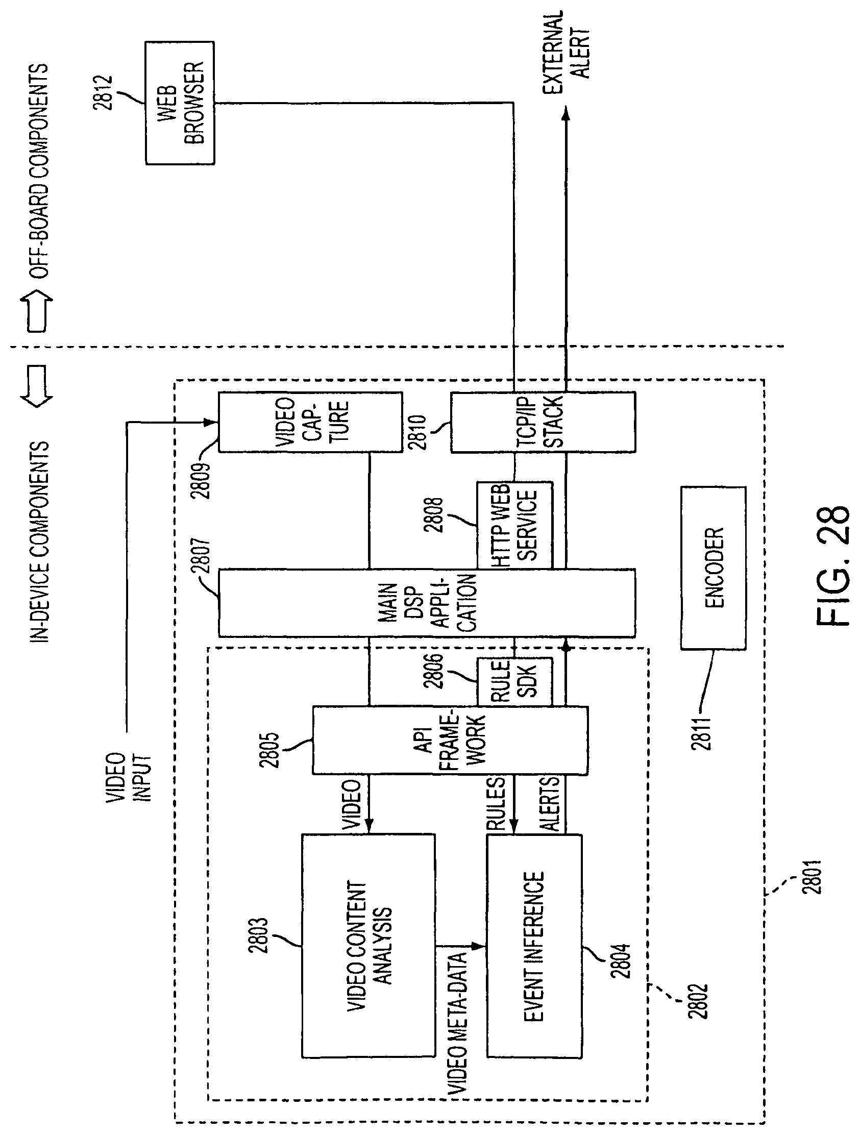
D00023

D00024

D00025

XML
uspto.report is an independent third-party trademark research tool that is not affiliated, endorsed, or sponsored by the United States Patent and Trademark Office (USPTO) or any other governmental organization. The information provided by uspto.report is based on publicly available data at the time of writing and is intended for informational purposes only.
While we strive to provide accurate and up-to-date information, we do not guarantee the accuracy, completeness, reliability, or suitability of the information displayed on this site. The use of this site is at your own risk. Any reliance you place on such information is therefore strictly at your own risk.
All official trademark data, including owner information, should be verified by visiting the official USPTO website at www.uspto.gov. This site is not intended to replace professional legal advice and should not be used as a substitute for consulting with a legal professional who is knowledgeable about trademark law.