Stereo image pickup unit
Ichihara , et al.
U.S. patent number 10,645,266 [Application Number 16/289,781] was granted by the patent office on 2020-05-05 for stereo image pickup unit. This patent grant is currently assigned to OLYMPUS CORPORATION. The grantee listed for this patent is OLYMPUS CORPORATION. Invention is credited to Jumpei Arai, Toshiyuki Fujii, Hirokazu Ichihara, Mayumi Imai, Teruyuki Nishihara, Masahiro Sato, Hiroshi Unsai.


View All Diagrams
| United States Patent | 10,645,266 |
| Ichihara , et al. | May 5, 2020 |
Stereo image pickup unit
Abstract
A stereo image pickup unit includes: first and second image pickup apparatuses including first and second image pickup devices and first and second mount boards, the image pickup apparatuses being formed in a same shape each other; and a holding frame for holding the first and second image pickup devices, the first and second mount boards including non-mounting surfaces perpendicular to rear surfaces of the first and second image pickup devices and projecting toward an outer side of projection surfaces of the first and second image pickup devices, the holding frame holding the first and second image pickup apparatuses such that the non-mounting surfaces are opposed to each other on a parallax direction inner side.
| Inventors: | Ichihara; Hirokazu (Hino, JP), Unsai; Hiroshi (Hachioji, JP), Fujii; Toshiyuki (Machida, JP), Imai; Mayumi (Hachioji, JP), Nishihara; Teruyuki (Suginami-ku, JP), Arai; Jumpei (Kitamoto, JP), Sato; Masahiro (Hachioji, JP) | ||||||||||
|---|---|---|---|---|---|---|---|---|---|---|---|
| Applicant: |
|
||||||||||
| Assignee: | OLYMPUS CORPORATION (Tokyo,
JP) |
||||||||||
| Family ID: | 62707163 | ||||||||||
| Appl. No.: | 16/289,781 | ||||||||||
| Filed: | March 1, 2019 |
Prior Publication Data
| Document Identifier | Publication Date | |
|---|---|---|
| US 20190199895 A1 | Jun 27, 2019 | |
Related U.S. Patent Documents
| Application Number | Filing Date | Patent Number | Issue Date | ||
|---|---|---|---|---|---|
| PCT/JP2017/031179 | Aug 30, 2017 | ||||
Foreign Application Priority Data
| Dec 26, 2016 [JP] | 2016-251715 | |||
| Current U.S. Class: | 1/1 |
| Current CPC Class: | A61B 1/00193 (20130101); A61B 1/053 (20130101); G02B 23/26 (20130101); H04N 13/204 (20180501); H04N 7/18 (20130101); A61B 1/051 (20130101); H04N 5/2252 (20130101); G03B 35/00 (20130101); H04N 5/2258 (20130101); H04N 5/2253 (20130101); H04N 5/2257 (20130101); H04N 13/239 (20180501); G02B 23/24 (20130101); G02B 23/2423 (20130101); G02B 7/021 (20130101); H04N 2005/2255 (20130101); G03B 17/55 (20130101); G03B 35/08 (20130101) |
| Current International Class: | H04N 5/225 (20060101); G03B 35/00 (20060101); H04N 7/18 (20060101); G02B 23/24 (20060101); A61B 1/05 (20060101); A61B 1/00 (20060101); G02B 23/26 (20060101); H04N 13/204 (20180101) |
| Field of Search: | ;348/42-45 |
References Cited [Referenced By]
U.S. Patent Documents
| 5860912 | January 1999 | Chiba |
| 6567115 | May 2003 | Miyashita |
| 8608645 | December 2013 | Boebel |
| 2004/0167378 | August 2004 | Ando |
| 2005/0267328 | December 2005 | Blumzvig et al. |
| 2014/0350338 | November 2014 | Tanaka |
| 2016/0259159 | September 2016 | Matsui |
| H07-323004 | Dec 1995 | JP | |||
| 2000-199863 | Jul 2000 | JP | |||
| 2000-258698 | Sep 2000 | JP | |||
| 2004-248957 | Sep 2004 | JP | |||
| 2005-525896 | Sep 2005 | JP | |||
| WO 03/098913 | Nov 2003 | WO | |||
Other References
|
International Search Report dated Nov. 21, 2017 issued in PCT/JP2017/031179. cited by applicant. |
Primary Examiner: Aggarwal; Yogesh K
Attorney, Agent or Firm: Scully, Scott, Murphy & Presser, P.C.
Parent Case Text
CROSS REFERENCE TO RELATED APPLICATION
This application is a continuation application of PCT/JP2017/031179 filed on Aug. 30, 2017 and claims benefit of Japanese Application No. 2016-251715 filed in Japan on Dec. 26, 2016, the entire contents of which are incorporated herein by this reference.
Claims
What is claimed is:
1. A stereo image pickup unit comprising: a pair of objective optical systems disposed having a parallax; a pair of image pickup apparatuses each including an image pickup device and a substrate connected to rear surface of the image pickup device; and a holding member configured to hold the pair of image pickup apparatuses such that optical images respectively formed by the pair of objective optical systems are guided to the image pickup devices of the pair of image pickup apparatuses, wherein the pair of image pickup apparatuses is formed in a same shape with respect to each other, the substrate included in each of the pair of image pickup apparatuses includes a plurality of surface sections perpendicular to the rear surface of the image pickup device, the plurality of surface sections include surface sections projecting from a direction of one side of the image pickup device toward an outer side of a projection surface of the image pickup device and formed by unmounting surfaces on which a component is not mounted, the holding member holds the pair of image pickup apparatuses such that the surface sections projecting toward the outer side of the projection surface are opposed to one another on a parallax direction inner side, and the substrate is a laminated substrate in which a plurality of circuit boards are laminated in the parallax direction.
2. The stereo image pickup unit according to claim 1, wherein, in the substrate, ground wires are connected to the surface sections opposed to each other on the parallax direction inner side and other signal wires are connected to the surface sections other than the surface sections opposed to each other on the parallax direction inner side.
3. The stereo image pickup unit according to claim 1, wherein the image pickup device included in each of the pair of image pickup apparatuses includes a cover glass, the holding member includes a single centering glass to which the cover glass is bonded, and the pair of image pickup apparatuses is held on the holding member by bonding the image pickup device to the holding member via the cover glass.
4. The stereo image pickup unit according to claim 1, wherein the pair of image pickup apparatuses is formed in a same shape each other and is held by the holding member in a state in which one of the image pickup apparatuses is rotated 180 degrees around an optical axis with respect to another of the image pickup apparatuses.
Description
BACKGROUND OF INVENTION
1. Field of the Invention
The present invention relates to a stereo image pickup unit capable of acquiring two picked-up images having a parallax.
2. Description of the Related Art
In recent years, in fields of a medical endoscope and an industrial endoscope, there have been increasing needs for stereoscopically observing a subject using a stereo image pickup unit.
For example, as disclosed in Japanese Patent Application Laid-Open Publication No. 2000-199863, a stereo image pickup unit used at a distal end portion of an endoscope is configured by disposing, in a pair in a left-right direction, image pickup units including optical lens systems formed by pluralities of lens groups such as objective lenses, solid-state image pickup chips (image pickup devices), and circuit boards (mount boards) on which circuit components such as capacitors, transistors, and resistors are mounted.
Further, Japanese Patent Application Laid-Open Publication No. 2000-199863 discloses a technique for configuring a device board and electronic components and terminal sections of signal cables mounted on the device board to be fit in a projection area of a solid-state image pickup chip in order to achieve a reduction in a diameter of an endoscope.
SUMMARY OF THE INVENTION
A stereo image pickup unit according to an aspect of the present invention is a stereo image pickup unit including: a pair of objective optical systems disposed having a parallax; a pair of image pickup apparatuses each including an image pickup device and a substrate connected to rear surface of the image pickup device; and a holding member configured to hold the pair of image pickup apparatuses such that optical images respectively formed by the pair of objective optical systems are guided to the image pickup devices of the pair of image pickup apparatuses. The pair of image pickup apparatuses is formed in a same shape each other. The substrate included in each of the pair of image pickup apparatuses includes a plurality of surface sections perpendicular to the rear surface of the image pickup device. The plurality of surface sections include surface sections projecting from a direction of one side of the image pickup device toward an outer side of a projection surface of the image pickup device and formed by unmounting surfaces on which a component is not mounted. The holding member holds the pair of image pickup apparatuses such that the surface sections projecting toward the outer side of the projection surface are opposed to one another on a parallax direction inner side. The substrate is a laminated substrate in which a plurality of circuit boards are laminated in the parallax direction
BRIEF DESCRIPTION OF THE DRAWINGS
FIG. 1 relates to an embodiment of the present invention and is a perspective view showing an overall configuration of an endoscope system;
FIG. 2 relates to the embodiment of the present invention and is an end face view of a distal end portion of an endoscope;
FIG. 3 relates to the embodiment of the present invention and is a III-III sectional view of FIG. 2;
FIG. 4 relates to the embodiment of the present invention and is a perspective view of a stereo image pickup unit;
FIG. 5 relates to the embodiment of the present invention and is an exploded perspective view of the stereo image pickup unit;
FIG. 6 relates to the embodiment of the present invention and is an exploded perspective view showing a positional relation between a projection surface of a first image pickup device and a first mount board;
FIG. 7 relates to the embodiment of the present invention and is an exploded perspective view showing a positional relation between a projection surface of a second image pickup device and a second mount board;
FIG. 8 relates to the embodiment of the present invention and is a rear view of the stereo image pickup unit;
FIG. 9 relates to a first modification and is an exploded perspective view showing a positional relation between a projection surface of a first image pickup device and a first mount board;
FIG. 10 relates to the first modification and is an exploded perspective view showing a positional relation between a projection surface of a second image pickup device and a second mount board;
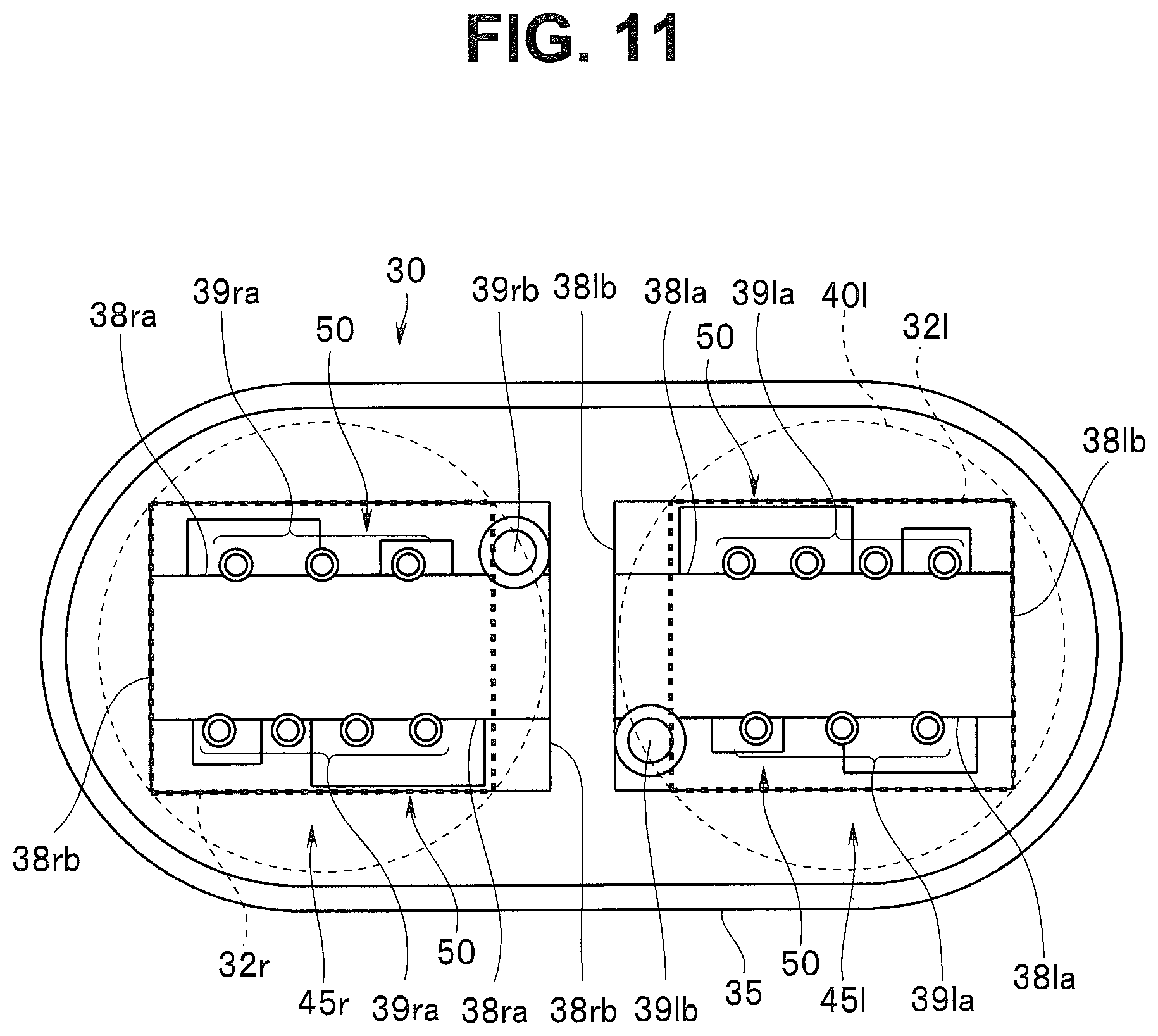
FIG. 11 relates to the first modification and is a rear view of a stereo image pickup unit;
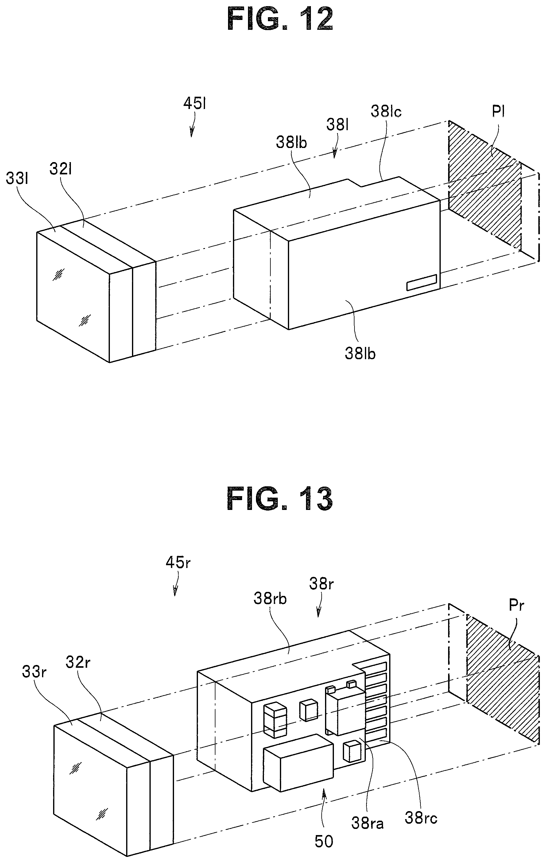
FIG. 12 relates to a second modification and is an exploded perspective view showing a positional relation between a projection surface of a first image pickup device and a first mount board;
FIG. 13 relates to the second modification and is an exploded perspective view showing a positional relation between a projection surface of a second image pickup device and a second mount board;
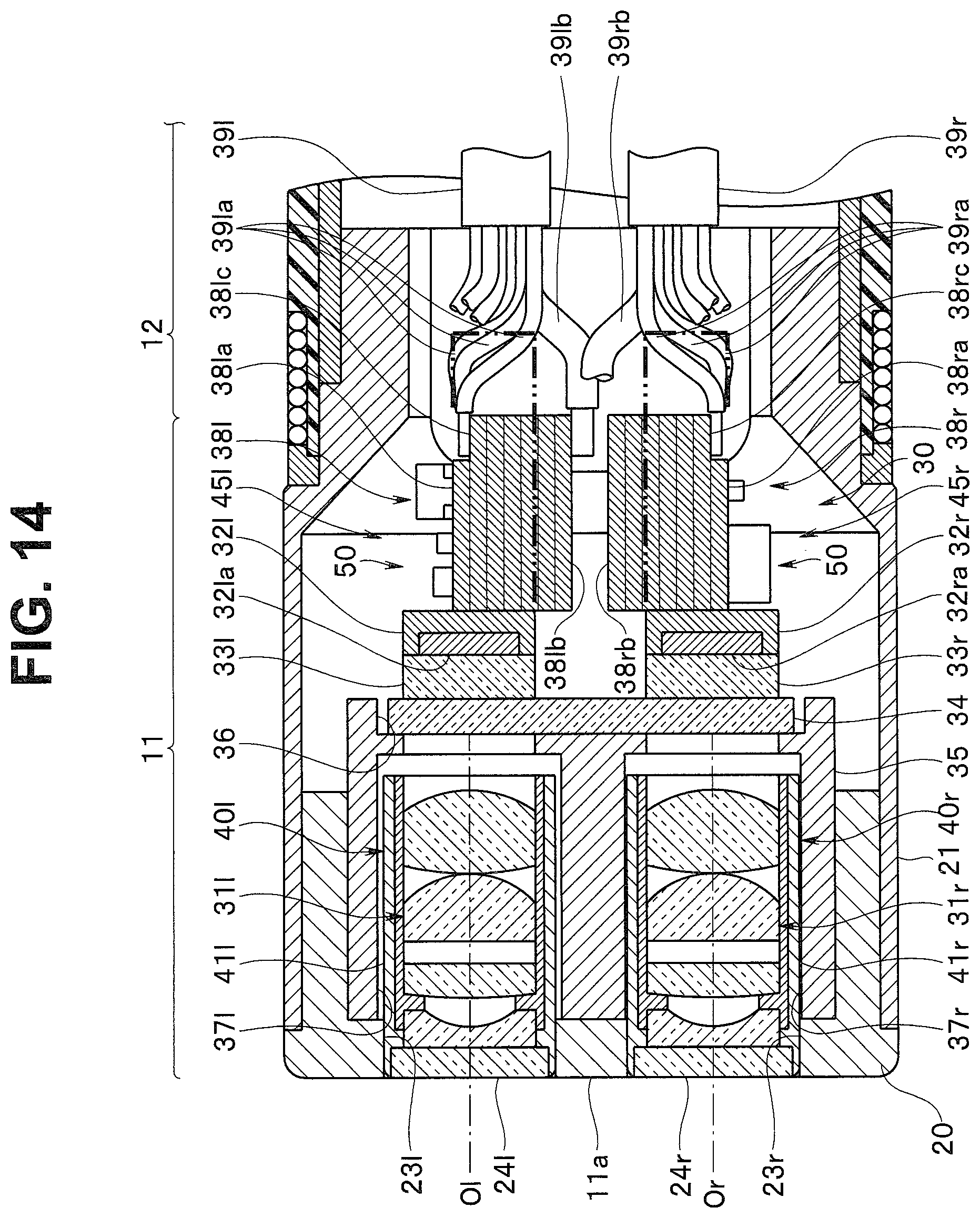
FIG. 14 relates to the second modification and is a main part sectional view of a distal end portion;
FIG. 15 relates to a third modification and is an exploded perspective view showing a positional relation between a projection surface of a first image pickup device and a first mount board;
FIG. 16 relates to the third modification and is an exploded perspective view showing a positional relation between a projection surface of a second image pickup device and a second mount board;
FIG. 17 relates to the third modification and is a rear view of a stereo image pickup unit;
FIG. 18 relates to the third modification and is a rear view of the stereo image pickup unit;
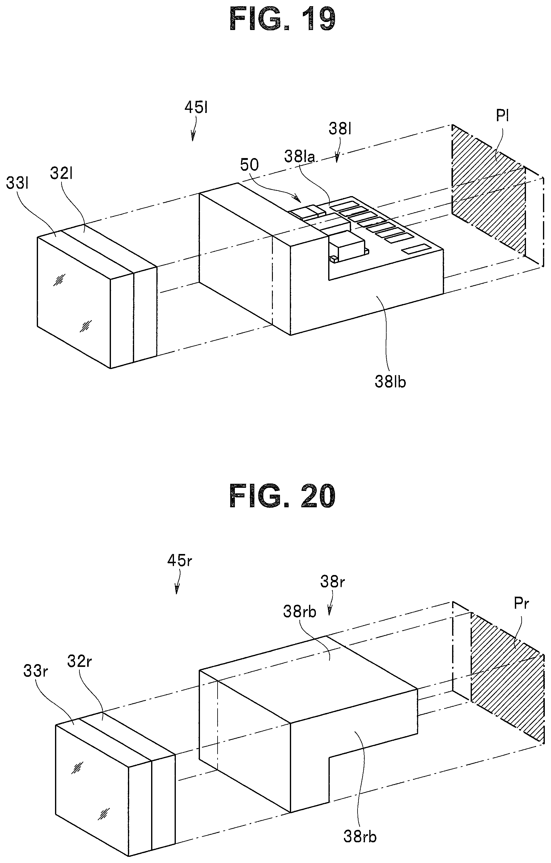
FIG. 19 relates to a fourth modification and is an exploded perspective view showing a positional relation between a projection surface of a first image pickup device and a first mount board;
FIG. 20 relates to the fourth modification and is an exploded perspective view showing a positional relation between a projection surface of a second image pickup device and a second mount board;
FIG. 21 relates to the fourth modification and is a rear view of a stereo image pickup unit;
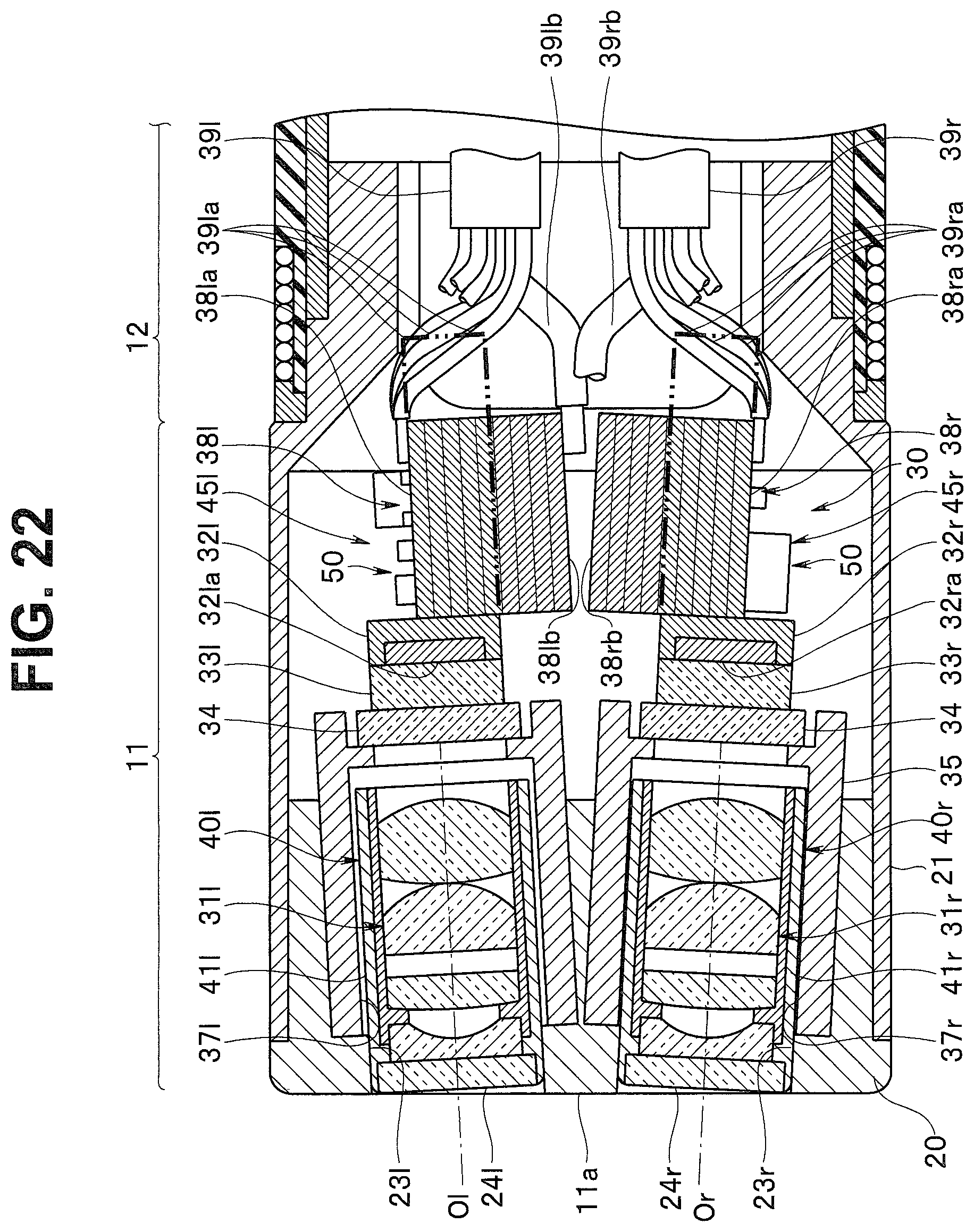
FIG. 22 relates to a fifth modification and is a main part sectional view of a distal end portion; and
FIG. 23 relates to a sixth modification and is a main part sectional view of a distal end portion.
DETAILED DESCRIPTION OF THE PREFERRED EMBODIMENT(S)
A form of the present invention is explained below with reference to the drawings. FIG. 1 to FIG. 8 relate to an embodiment of the present invention. FIG. 1 is a perspective view showing an overall configuration of an endoscope system. FIG. 2 is an end face view of a distal end portion of an endoscope. FIG. 3 is a III-III sectional view of FIG. 2. FIG. 4 is a perspective view of a stereo image pickup unit. FIG. 5 is an exploded perspective view of the stereo image pickup unit. FIG. 6 is an exploded perspective view showing a positional relation between a projection surface of a first image pickup device and a first mount board. FIG. 7 is an exploded perspective view showing a positional relation between a projection surface of a second image pickup device and a second mount board. FIG. 8 is a rear view of the stereo image pickup unit.
An endoscope system 1 shown in FIG. 1 includes a stereoscopic endoscope 2 capable of stereoscopically picking up images of a subject from different visual points, a processor 3 to which the stereoscopic endoscope 2 is detachably connected, and a monitor 5 functioning as a display apparatus that displays, as an endoscopic image, an image signal generated by the processor 3.
The stereoscopic endoscope 2 in the present embodiment is, for example, a rigid endoscope applied to laparoscopic surgery. The stereoscopic endoscope 2 includes an elongated insertion section 6, an operation section 7 concatenated to a proximal end side of the insertion section 6, and a universal cable 8 extending from the operation section 7 and connected to the processor 3.
A distal end portion 11 mainly configured by a member made of metal such as stainless steel, a bending section 12, and a rigid tube section 13 configured by a tube of metal such as stainless steel are concatenated in the insertion section 6 in order from a distal end side.
The insertion section 6 is a portion inserted into a body. A stereo image pickup unit 30 (see FIG. 3) for stereoscopically picking up an image of an inside of a subject is incorporated in the distal end portion 11. Image pickup cable bundles 39l and 39r (see FIG. 3) electrically connected to the stereo image pickup unit 30, a light guide bundle (not shown in the figure) that transmits illumination light to the distal end portion 11, and the like are inserted through insides of the bending section 12 and the rigid tube section 13. Note that the stereoscopic endoscope 2 in the present embodiment illustrates a rigid endoscope, a proximal end side of which further than the bending section 12 is configured by the rigid tube section 13. However, the stereoscopic endoscope 2 is not limited to this and may be a flexible endoscope, a proximal end side of which further than the bending section 12 is configured by a flexible tube section having flexibility.
Note that, in the following explanation, an up-down direction and a left-right direction of respective sections refer to an up-down direction and a left-right direction corresponding to an up-down direction and a left-right direction of an image picked up by the stereo image pickup unit 30 and displayed on the monitor 5.
Angle levers 15 for remotely operating the bending section 12 are provided in the operation section 7. Further, various switches 16 for operating a light source device, a video system sensor, and the like of the processor 3 are provided.
The angle levers 15 are bending operation means capable of performing bending operation of the bending section 12 of the insertion section 6 in up, down, left, and right four directions here. Note that the bending section 12 is not limited to be configured to be bendable in the up, down, left, and right four directions and may be configured to be bendable in, for example, only up and down two directions or left and right two directions.
A configuration of a distal end portion of such a stereoscopic endoscope 2 is explained in detail with reference to FIGS. 2 and 3.
As shown in FIG. 3, the distal end portion 11 includes a distal end portion main body 20 formed in a substantially columnar shape and a distal end cylinder body 21 formed in a substantially cylindrical shape, a distal end of which is fixed to the distal end portion main body 20. The distal end of the distal end cylinder body 21 is fit in an outer periphery of the distal end portion main body 20. A distal end face 11a of the distal end portion 11 is formed by an end face of the distal end portion main body 20 exposed from the distal end cylinder body 21.
As shown in FIGS. 2 and 3, in the distal end portion main body 20, a pair of through-holes for observation 23l and 23r opening on the distal end face 11a is provided side by side on the left and the right (i.e., in a left and right bending direction by the bending section 12). A pair of objective optical systems (first and second objective optical systems 31l and 31r) configuring the stereo image pickup unit 30 is respectively held in the left and right respective through-holes for observation 23l and 23r. Consequently, observation windows 24l and 24r are formed on the distal end face 11a of the distal end portion 11.
For example, as shown in FIG. 2, above the through-holes for observation 23l and 23r (i.e., above in an up and down bending direction by the bending section 12), a pair of through-holes for illumination 25l and 25r opening on the distal end face 11a is provided side by side on the left and the right in the distal end portion main body 20. A pair of illumination optical systems 27l and 27r optically connected to a not-shown light guide bundle is respectively held in the left and right respective through-holes for illumination 25l and 25r. Consequently, illumination windows 26l and 26r are formed on the distal end face 11a of the distal end portion 11.
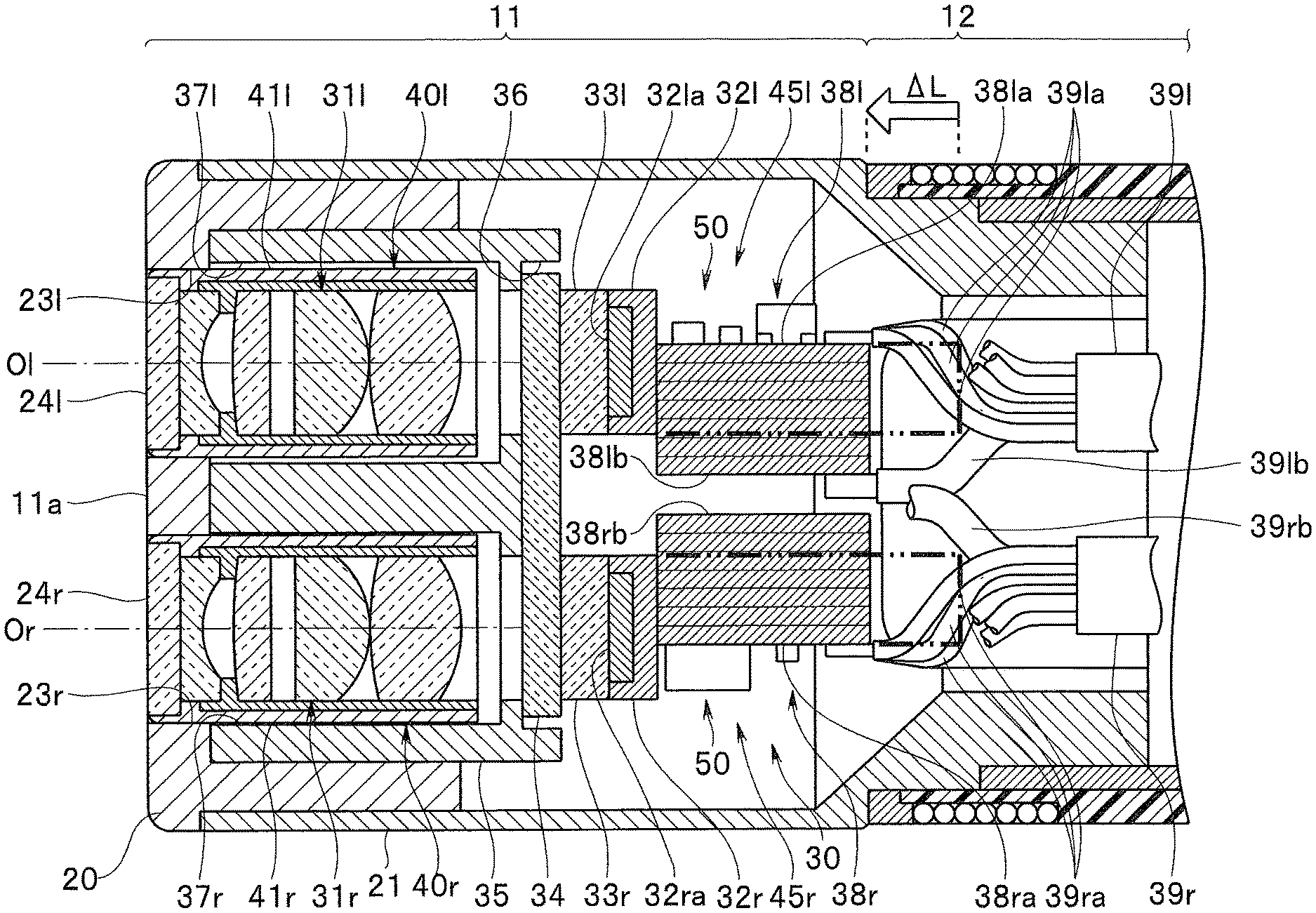
As shown in FIG. 3 to FIG. 5, the stereo image pickup unit 30 includes a first image pickup device 32l that receives an optical image (a first optical image) formed by the first objective optical system 31l, a second image pickup device 32r that receives an optical image (a second optical image) formed by the second objective optical system 31r, a single centering glass 34 functioning as a holding member disposed on optical paths of the first and second optical images, respective light receiving surfaces 32la and 32ra sides of the first and second image pickup devices 32l and 32r being positioned and fixed on the centering glass 34 by bonding, and a holding frame 35 functioning as a holding member that holds the first and second image pickup devices 32l and 32r via the centering glass 34.
The first and second image pickup devices 32l and 32r are configured by a solid-state image pickup device such as a CCD (charge coupled device) or a CMOS (complementary metal oxide semiconductor). Cover glasses 33l and 33r for protecting the light receiving surfaces 32la and 32ra are stuck to the first and second image pickup devices 32l and 32r.
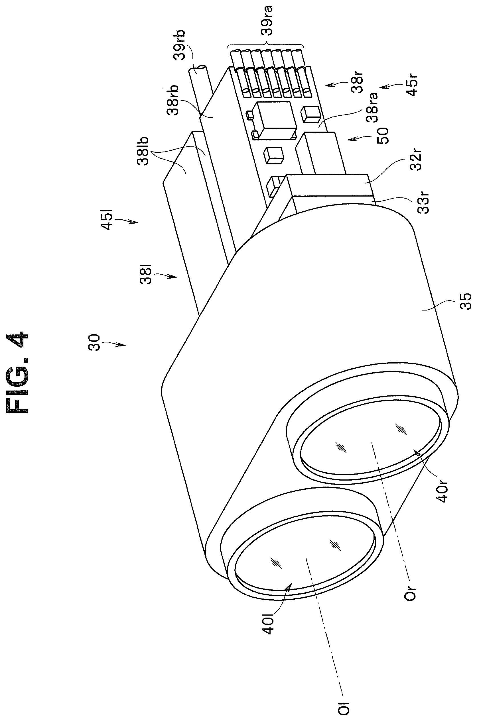
First and second mount boards 38l and 38r functioning as substrates are connected to rear surfaces of the first and second image pickup devices 32l and 32r. The first and second mount boards 38l and 38r are respectively electrically connected to the first and second image pickup devices 32l and 32r via terminal sections (not shown in the figures) provided in the first and second image pickup devices 32l and 32r. First and second image pickup sections 45l and 45r, which are first and second image pickup apparatuses, are respectively configured by the first and second image pickup devices 32l and 32r and the first and second mount boards 38l and 38r.
Various electronic components such as digital ICs for generating driving signals for the first and second image pickup devices 32l and 32r, nonvolatile memories (EEPROMs) having stored therein control parameters, capacitors for IC driving power supply stabilization for stabilizing driving power supplies for the ICs, and resistors are respectively mounted on the respective first and second mount boards 38l and 38r by soldering or the like. As the control parameters, serial numbers (manufacturing numbers of a manufacturer) of the image pickup devices, correction data for correcting a white flaw of the image pickup devices, and the like are included. If it is difficult to mount a nonvolatile memory to correspond to each of the first and second image pickup devices 32l and 32r, the control parameters of the two image pickup devices may be collectively stored in one nonvolatile memory. In this case, the nonvolatile memory only has to be mounted on a substrate provided in the operation section 7 or in an inside of the endoscope other than the operation section 7. Image pickup cable bundles 39l and 39r are electrically connected to the respective mount boards 38l and 38r.
The centering glass 34 is configured by a transparent glass substrate extending in the left-right direction of the distal end portion 11. The light receiving surfaces 32la and 32ra sides of the first and second image pickup devices 32l and 32r are fixed to the centering glass 34 via the cover glasses 33l and 33r, respectively.
More specifically, the cover glasses 33l and 33r stuck to the light receiving surfaces 32la and 32ra are bonded to the centering glass 34 via an ultraviolet-curing transparent adhesive (a UV adhesive) or the like, whereby the first and second image pickup devices 32l and 32r are positioned and fixed in a state in which the first and second image pickup devices 32l and 32r are separated by a predetermined interval from each other.
The holding frame 35 is configured by a columnar metal member, a sectional shape of which is formed in a substantially rounded rectangular shape, (see, for example, FIG. 5). A glass holding section 36 is recessed on a proximal end side of the holding frame 35. The centering glass 34 is fixed to the glass holding section 36 by an adhesive or the like.
For example, as shown in FIGS. 3 and 5, a first objective optical system holding hole 37l and a second objective optical system holding hole 37r are provided side by side at a preset interval apart from each other in the holding frame 35. The first and second objective optical system holding holes 37l and 37r are configured by through-holes, distal end sides of which are opened on an end face (the distal end face 11a) of the holding frame 35 and proximal end sides of which communicate with the glass holding section 36.
The first and second objective optical systems 31l and 31r are respectively held in the first and second objective optical system holding holes 37l and 37r while having a predetermined parallax in a state in which the first and second objective optical systems 31l and 31r are unitized as first and second objective optical system units 40l and 40r.
That is, the first and second objective optical systems 31l and 31r are respectively held by first and second lens frames 41l and 41 r to thereby configure the first and second objective optical system units 40l and 40r. The first and second objective optical system units 40l and 40r are positioned and fixed via an adhesive or the like in the first and second objective optical system holding holes 37l and 37r, whereby the first and second objective optical systems 31l and 31r are integrally held by the single holding frame 35 together with the first and second image pickup devices 32l and 32r.
A specific configuration of the first and second image pickup sections 45l and 45r is explained with reference to FIG. 3 to FIG. 8.
In the present embodiment, the first and second image pickup sections 45l and 45r are respectively module components formed in the same shape each other respectively configured by image pickup devices and mount boards formed in common specifications and a common shape. The first and second image pickup sections 45l and 45r are held by the holding frame 35 (the centering glass 34) in a state in which the first and second image pickup sections 45l and 45r are reversed 180 degrees with respect to each other (i.e., for example, in a state in which [with respect to the first image pickup section 45l, which is one image pickup section] the second image pickup section 45r, which is the other image pickup section, is rotated 180 degrees around an optical axis Or). Note that, when the first and second image pickup devices 32l and 32r configuring the first and second image pickup sections 45l and 45r are CMOSs, order for reading out image pickup signals from the first and second image pickup devices 32l and 32r is set such that the image pickup signals are reversed.
As shown in FIG. 3, the first and second mount boards 38l and 38r in the present embodiment are configured by laminated substrates in which pluralities of circuit boards are laminated in a parallax direction. That is, the first and second mount boards 38l and 38r are configured by hard bulk-like laminated substrates formed in a substantially cubic shape having planar surface sections respectively in the up-down direction and the left-right direction of optical axes Ol and Or.
Surface sections on a parallax direction outer side among respective surface sections of the first and second mount boards 38l and 38r are set as mounting surfaces 38la and 38ra. Pluralities of lands are formed on the respective mounting surfaces 38la and 38ra of the first and second mount boards 38l and 38r. Various electronic components 50 are mounted on the respective mounting surfaces 38la and 38ra of the first and second mount boards 38l and 38r via the respective lands. Various signal wires 39la and 39ra (excluding ground wires 39lb and 39rb explained below) branched from the image pickup cable bundles 39l and 39r are electrically connected to the respective mounting surfaces 38la and 38ra.
On the other hand, respective surface sections in the up-down direction and surface sections on a parallax direction inner side among the respective surface sections of the first and second mount boards 38l and 38r are set as the non-mounting surfaces 38la and 38ra on which various electronic components are not mounted. However, only lands for grounding are formed on the surface sections on the parallax direction inner side of the first and second mount boards 38l and 38r. The ground wires 39lb and 39rb branched from the image pickup cable bundles 39l and 39r are electrically connected to the surface sections via the lands for grounding.
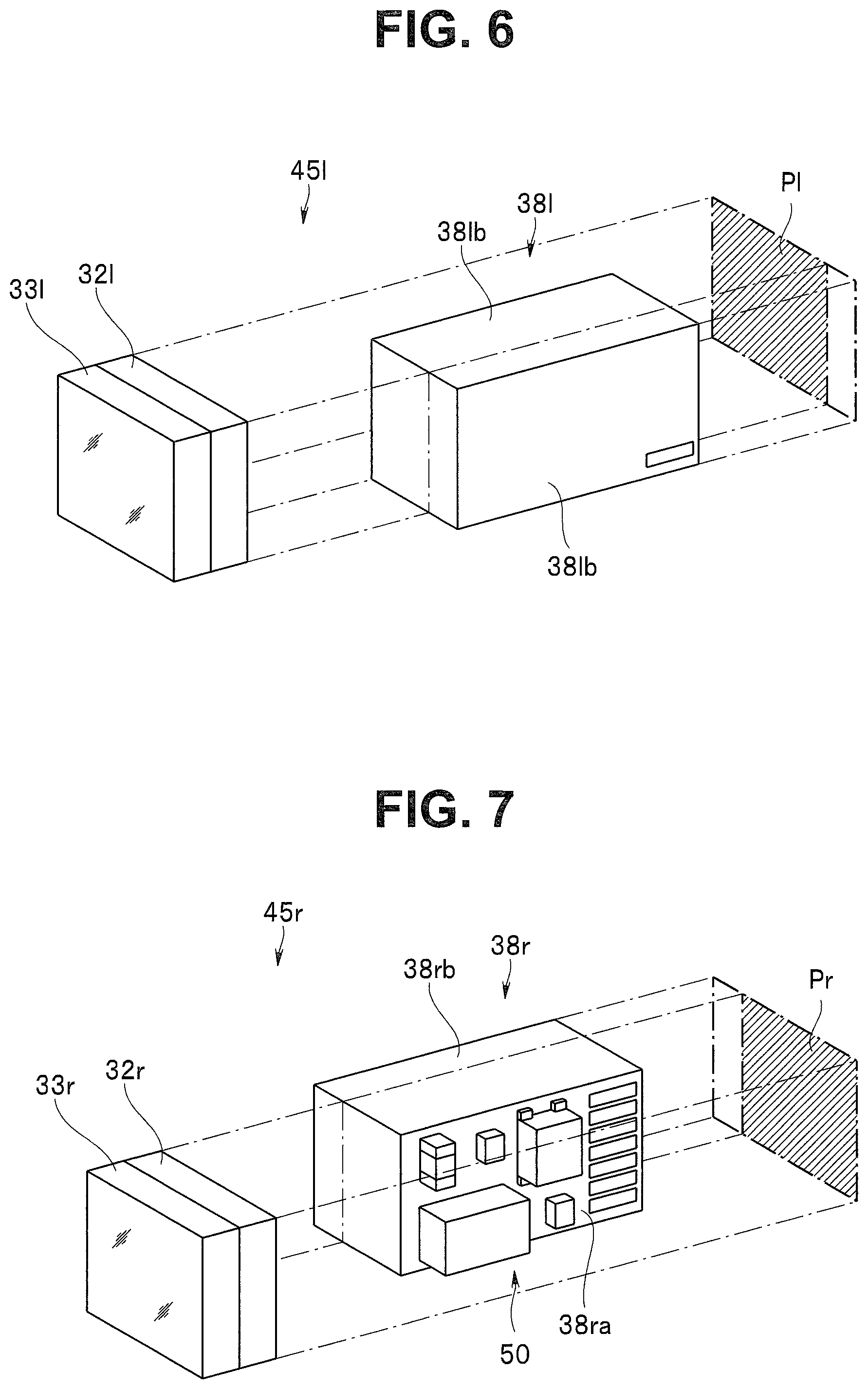
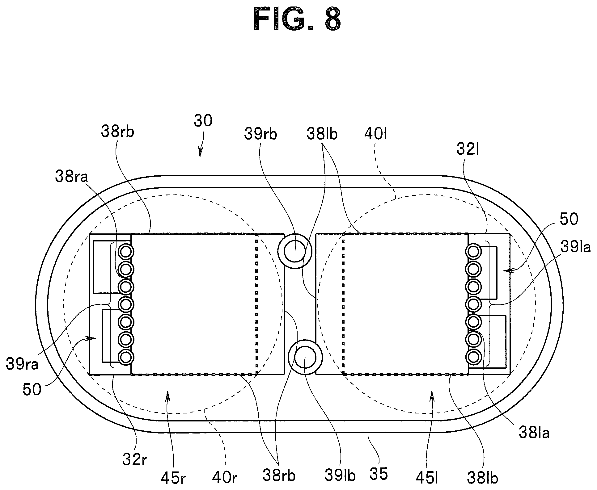
As shown in FIG. 3 to FIG. 8, the first and second mount boards 38l and 38r configured in this way are concatenated to proximal end sides of the first and second image pickup devices 32l and 32r in a state in which the respective surface sections (non-mounting surfaces 38lb and 38rb) in the up-down direction and the various electronic components 50 mounted on the surface sections (the mounting surfaces 38la and 38ra) on the parallax direction outer side are positioned not to project to the up-down direction and the parallax direction outer side of projection surfaces Pl and Pr in the optical axes Ol and Or direction of the first and second image pickup devices 32l and 32r and the surface sections (the non-mounting surfaces 38lb and 38rb) on the parallax direction inner side are positioned to project to the outer side (the parallax direction inner side) from the projection surfaces Pl and Pr and to be opposed to each other.
That is, height in the up-down direction of the first and second mount boards 38l and 38r are set to substantially the same height as height of the first and second image pickup devices 32l and 32r. The first and second mount boards 38l and 38r are positioned such that the respective surface sections in the up-down direction extend substantially flush with upper surfaces and lower surfaces of the first and second image pickup devices 32l and 32r.
The first and second mount boards 38l and 38r are positioned such that the surfaces (the mounting surfaces 38la and 38ra) on the parallax direction outer side are offset further to the inner side than surfaces on the parallax direction outer side of the first and second image pickup devices 32l and 32r.
Further, the first and second mount boards 38l and 38r are positioned such the surface sections (the non-mounting surfaces 38lb and 38rb) on the parallax direction inner side are offset further to the outer sides than surfaces on the parallax direction inner side of the first and second image pickup devices 32l and 32r within a range in which the surface sections (the non-mounting surfaces 38lb and 38rb) on the parallax direction inner side are not in contact with each other.
In other words, the first and second mount boards 38l and 38r are configured by laminated substrates in which pluralities of circuit boards are laminated in the parallax direction without causing various electronic components mounted on the surface sections on the parallax direction outer side to project from the projection surfaces Pl and Pr and within a range in which the surface sections on the parallax direction inner side are not in contact with each other. The pluralities of circuit boards are laminated to a position where the pluralities of circuit boards project to the parallax direction inner side. A volume (an effective circuit area) of the laminated substrates is secured. Consequently, length in the optical axes Ol and Or direction of the first and second mount boards 38l and 38r is reduced by .DELTA.L compared with when all of the surface sections and the various electronic components are fit within the projection surfaces Pl and Pr (see, alternate long and two short dashes lines in FIG. 3). As a result of reducing the length in the optical axes Ol and Or direction of the first and second mount boards 38l and 38r in this way, a hard length of the distal end portion 11 is also reduced.
According to such an embodiment, the first and second mount boards 38l and 38r including pluralities of surface sections perpendicular to the rear surfaces of the first and second image pickup devices 32l and 32r are connected to the rear surfaces of the first and second image pickup devices 32l and 32r to configure the first and second image pickup sections 45l and 45r formed in the same shape each other. Among the respective surface sections of the first and second mount boards 38l and 38r, one of the surface sections formed by each of the non-mounting surfaces 38lb and 38rb on which electronic components are not mounted is caused to project from a direction of one side of each of the first and second image pickup devices 32l and 32r toward the outer side of the projection surfaces Pl and Pr. The holding frame 35 (the centering glass 34) is caused to hold the first and second image pickup sections 45l and 45r in a state in which the first and second image pickup sections 45l and 45r are reversed 180 degrees around the optical axes Ol and Or from each other such that the projecting surface sections (the non-mounting surfaces) are opposed to each other in the parallax direction inner side. Consequently, it is possible to effectively reduce the hard length of the distal end portion 11 without increasing the distal end portion 11 in a diameter.
That is, the first and second mount boards 38l and 38r are positioned such that the respective surface sections (the non-mounting surfaces 38lb and 38rb) in the up-down direction and the various electronic components 50 mounted on the surface sections (the mounting surfaces 38la and 38ra) on the parallax direction outer side do not project to the up-down direction and the parallax direction outer side of the projection surfaces Pl and Pr of the first and second image pickup devices 32l and 32r. Further, the first and second mount boards 38l and 38r are concatenated to the proximal end sides of the first and second image pickup devices 32l and 32r in a state in which the surface sections on the parallax direction inner side are set as the non-mounting surfaces 38lb and 38rb, on which electronic components are not mounted, and positioned to project to the parallax direction inner side from the projection surfaces Pl and Pr and to be opposed to each other. Consequently, it is possible to effectively reduce the hard length of the distal end portion 11 without increasing the distal end portion 11 in a diameter.
In other words, the respective surface sections in the up-down direction of the first and second mount boards 38l and 38r and the various electronic components 50 mounted on the surface sections (the mounting surfaces 38la and 38ra) on the parallax direction outer side are positioned not to project to the up-down direction and the parallax direction outer side of the projection surfaces Pl and Pr of the first and second image pickup devices 32l and 32r. Consequently, it is possible to effectively prevent an increase in a diameter of the distal end portion 11. On the other hand, the surfaces (the non-mounting surfaces 38lb and 38rb) on the parallax direction inner side of the first and second mount boards 38l and 38r are positioned to project to the parallax direction inner side from the projection surfaces Pl and Pr to be opposed to each other. Consequently, it is possible to effectively utilize an interval set between the optical axes Ol and Or in order to secure a left-right parallax, without forming the interval as a dead space and secure a volume (an effective circuit area) of the first and second mount boards 38l and 38r. As a result, for example, it is possible to reduce length in the optical axes Ol and Or direction of the first and second mount boards 38l and 38r compared with when all of the surface sections and the various electronic components 50 are fit within the projection surfaces Pl and Pr (see, the alternate long and two short dashes lines in FIG. 3). Accordingly, it is possible to effectively reduce the hard length of the distal end portion 11.
In this case, the surface sections on the parallax direction inner side of the first and second mount boards 38l and 38r are set as the non-mounting surfaces 38lb and 38rb on which electronic components are not mounted. Consequently, even when the first and second mount boards 38l and 38r are brought close to the parallax direction inner side, it is possible to effectively prevent interference due to a so-called crosstalk or the like between electronic components on the first and the second mount boards 38l and 38r.
Further, the ground wires 39lb and 39rb are connected to the non-mounting surfaces 38lb and 38rb on the parallax direction inner side where the first and second mount boards 38l and 38r are opposed to each other. Consequently, even when the first and second mount boards 38l and 38r are brought close, it is possible to quickly radiate heat through the ground wires 39lb and 39rb. Further, it is possible to realize a shield effect against the crosstalk or the like and more effectively prevent the interference between the electronic components on the first and second mount boards 38l and 38r.
Further, the first and second image pickup sections 45l and 45r are formed in the same shape respectively configured by the image pickup devices and the mount boards respectively formed in the common specifications and the common shape. The first and second image pickup sections 45l and 45r are held by the centering glass 34 in a state in which with respect to one image pickup section the other image pickup section is rotated 180 degrees around the optical axis. Therefore, it is unnecessary to form the first and second image pickup sections 45l and 45r as dedicated components respectively for the left and the right. It is possible to effectively reduce a manufacturing manhour, manufacturing cost, and the like.
For example, as shown in FIG. 9 to FIG. 11, the respective surface sections in the up-down direction of the first and second mount boards 38l and 38r are configured by stepped surface sections. Consequently, it is also possible to form the first and second mount boards 38l and 38r as irregular-shaped boards formed in a T shape in a side view.
With such a configuration, it is possible to effectively use the respective surface sections in the up-down direction of the first and second mount boards 38l and 38r as the mounting surfaces 38la and 38ra.
For example, as shown in FIG. 12 to FIG. 14, it is also possible to form step sections 38lc and 38rc on proximal end sides of the respective surface sections (the mounting surfaces) on the parallax direction outer side of the first and second mount boards 38l and 38r and provide, in the respective step sections 38lc and 38rc, lands for electrically connecting the various signal wires 39la and 39ra.
With such a configuration, it is possible to more effectively avoid the interference between the distal end cylinder body 21 and the various signal wires 39la and 39ra on a proximal end side of the distal end portion 11. It is possible to more effectively reduce the hard length of the distal end portion 11.
From the same reason, for example, as shown in FIG. 15 to FIG. 18, it is also possible to form inclined surfaces 38ld and 38rd on the proximal end sides of the respective surface sections (the mounting surfaces) on the parallax direction outer side of the first and second mount boards 38l and 38r and provide, on the respective inclined surfaces 38ld and 38rd, lands for electrically connecting the various signal wires 39la and 39ra.
In addition, it is also possible to provide a pair of upper and lower cutout sections 38le and 38re on the respective surface sections (the non-mounting surfaces) on the parallax direction inner side of the first and second mount boards 38l and 38r and provide lands for grounding in the respective cutout sections 38le and 38re.
With such a configuration, for example, as shown in FIG. 17, it is possible to connect the ground wires 39lb and 39rb to the first and second mount boards 38l and 38r from the same direction. Further, for example, as shown in FIG. 18, it is possible to connect a common ground wire 39b formed in a large diameter to the first and second mount boards 38l and 38r.
For example, as shown in FIG. 19 to FIG. 21, a surface section in an upward direction of the first mount board 38l and a surface section in a downward direction of the second mount board 38r are configured by stepped surface sections. Consequently, it is also possible to form the first and second mount boards 38l and 38r as irregular-shaped boards formed in an L shape in a side view.
With such a configuration, it is possible to effectively use the respective surface sections in the up-down direction of the first and second mount boards 38l and 38r as the mounting surfaces 38la and 38ra. In addition, the surface section in the upward direction of the first mount board 38l and the surface section in the downward direction of the second mount board 38r are formed as the mounting surfaces 38la and 38ra. Consequently, even when either one of the mounting surfaces 38la and 38ra is directed to an upper side, for example, during assembly of the stereo image pickup unit 30, it is possible to cause a soldering iron to access the mounting surfaces 38la and 38ra from a right side. Therefore, it is possible to easily perform soldering work or the like by the soldering iron generally gripped by a right hand.
For example, as shown in FIG. 22, it is possible to adopt the same configuration as the configuration in the embodiment explained above in the stereo image pickup unit 30 of a so-called Greenough type in which the optical axes Ol and Or of the first and second objective optical system units 40l and 40r are set in non-parallel.
For example, as shown in FIG. 23, the first and second mount boards 38l and 38r are not limited to the hard laminated substrates and may be soft flexible substrates. In this case, the first and second mount boards 38l and 38r are disposed such that the non-mounting surfaces project to the parallax direction inner side with respect to the projection surfaces Pl and Pr. The proximal end sides of the first and second mount boards 38l and 38r are folded back to the parallax direction outer side. Consequently, it is possible to achieve substantially the same effects as the effects in the embodiment explained above.
Note that the present invention is not limited to the embodiments explained above. Various modifications and changes are possible. The modifications and changes are also within the technical scope of the present invention. For example, it goes without saying that the configurations of the embodiment and the respective modifications may be combined as appropriate.
* * * * *
D00000
D00001
D00002
D00003
D00004
D00005
D00006
D00007
D00008
D00009
D00010
D00011
D00012

D00013

D00014
D00015

D00016
D00017

XML
uspto.report is an independent third-party trademark research tool that is not affiliated, endorsed, or sponsored by the United States Patent and Trademark Office (USPTO) or any other governmental organization. The information provided by uspto.report is based on publicly available data at the time of writing and is intended for informational purposes only.
While we strive to provide accurate and up-to-date information, we do not guarantee the accuracy, completeness, reliability, or suitability of the information displayed on this site. The use of this site is at your own risk. Any reliance you place on such information is therefore strictly at your own risk.
All official trademark data, including owner information, should be verified by visiting the official USPTO website at www.uspto.gov. This site is not intended to replace professional legal advice and should not be used as a substitute for consulting with a legal professional who is knowledgeable about trademark law.