Touch sensitive device with multi-sensor stream synchronized data
Harrison
U.S. patent number 10,642,404 [Application Number 14/834,434] was granted by the patent office on 2020-05-05 for touch sensitive device with multi-sensor stream synchronized data. This patent grant is currently assigned to QEEXO, CO.. The grantee listed for this patent is QEEXO, CO.. Invention is credited to Christopher Harrison.
| United States Patent | 10,642,404 |
| Harrison | May 5, 2020 |
Touch sensitive device with multi-sensor stream synchronized data
Abstract
Touch sensitive devices having sensor systems and sensor systems for use with touch sensitive devices are provided. A vibration sensor senses vibrations and a touch sensor senses contact with an object. Vibration data representing sensed vibration is stored in a sensor data memory and touch data indicative of contact between the object and the touch sensitive surface is stored in the sensor data memory in temporal association with the vibration data. The touch data and the temporal association with vibration data can be used to identify segments of the vibration data that are of interest.
| Inventors: | Harrison; Christopher (Pittsburgh, PA) | ||||||||||
|---|---|---|---|---|---|---|---|---|---|---|---|
| Applicant: |
|
||||||||||
| Assignee: | QEEXO, CO. (Mountain View,
CA) |
||||||||||
| Family ID: | 58098139 | ||||||||||
| Appl. No.: | 14/834,434 | ||||||||||
| Filed: | August 24, 2015 |
Prior Publication Data
| Document Identifier | Publication Date | |
|---|---|---|
| US 20170060279 A1 | Mar 2, 2017 | |
| Current U.S. Class: | 1/1 |
| Current CPC Class: | G06F 3/04166 (20190501); G06F 3/0416 (20130101); G06F 3/044 (20130101); G06F 3/043 (20130101); G06F 2203/04106 (20130101); G06F 2203/04101 (20130101) |
| Current International Class: | G06F 3/043 (20060101); G06F 3/041 (20060101); G06F 3/044 (20060101) |
References Cited [Referenced By]
U.S. Patent Documents
| 2008028 | July 1935 | Mccortney et al. |
| 2430005 | November 1947 | Denneen et al. |
| 3354531 | November 1967 | Pryor |
| 4561105 | December 1985 | Crane et al. |
| 4597932 | July 1986 | Kurihara et al. |
| 4686332 | August 1987 | Greanias et al. |
| 5483261 | January 1996 | Yasutake |
| 5544265 | August 1996 | Bozinovic et al. |
| 5596656 | January 1997 | Goldberg |
| 5615285 | March 1997 | Beernink |
| 5625818 | April 1997 | Zarmer et al. |
| 5666438 | September 1997 | Beernink et al. |
| 5867163 | February 1999 | Kurtenbach |
| 5933514 | August 1999 | Ostrem et al. |
| 6028593 | February 2000 | Rosenberg et al. |
| 6118435 | September 2000 | Fujita et al. |
| 6208330 | March 2001 | Hasegawa et al. |
| 6212295 | April 2001 | Ostrem et al. |
| 6222465 | April 2001 | Kumar et al. |
| 6246395 | June 2001 | Goyins et al. |
| 6252563 | June 2001 | Tada et al. |
| 6323846 | November 2001 | Westerman et al. |
| 6337698 | January 2002 | Kelly, Jr. et al. |
| 6492979 | December 2002 | Kent et al. |
| 6504530 | January 2003 | Wilson et al. |
| 6643663 | November 2003 | Dabney et al. |
| 6707451 | March 2004 | Nagaoka |
| 6748425 | June 2004 | Duffy et al. |
| 6772396 | August 2004 | Cronin et al. |
| 6933930 | August 2005 | Devige et al. |
| 6943665 | September 2005 | Chornenky |
| 7050955 | May 2006 | Carmel et al. |
| 7084884 | August 2006 | Nelson et al. |
| 7098896 | August 2006 | Kushler et al. |
| 7212197 | May 2007 | Schkolne et al. |
| 7443396 | October 2008 | Ilic |
| 7581194 | August 2009 | Iwema et al. |
| 7982724 | July 2011 | Hill |
| 8086971 | December 2011 | Radivojevic et al. |
| 8144126 | March 2012 | Wright |
| 8154524 | April 2012 | Wilson et al. |
| 8154529 | April 2012 | Sleeman et al. |
| 8170346 | May 2012 | Ludwig |
| 8199126 | June 2012 | Taubman |
| 8253744 | August 2012 | Macura et al. |
| 8269744 | September 2012 | Agari et al. |
| 8327029 | December 2012 | Purser |
| 3441790 | May 2013 | Pance et al. |
| 8547357 | October 2013 | Aoyagi |
| 8624878 | January 2014 | Sarwar et al. |
| 8670632 | March 2014 | Wilson |
| 8674943 | March 2014 | Westerman et al. |
| 8743091 | June 2014 | Bernstein |
| 8760395 | June 2014 | Kim et al. |
| 8762332 | June 2014 | Keebler et al. |
| 8769524 | July 2014 | Bhullar et al. |
| 9013452 | April 2015 | Harrison et al. |
| 9019244 | April 2015 | Harrison |
| 9030498 | May 2015 | Galor et al. |
| 9052772 | June 2015 | West |
| 9060007 | June 2015 | Keebler et al. |
| 9182882 | November 2015 | Fowler et al. |
| 9329688 | May 2016 | Harrison |
| 9329715 | May 2016 | Schwarz et al. |
| 9377863 | June 2016 | Bychkov et al. |
| 9557852 | January 2017 | Tsai et al. |
| 9612689 | April 2017 | Harrison et al. |
| 9696859 | July 2017 | Heller et al. |
| 9864453 | January 2018 | Munemoto et al. |
| 10082935 | September 2018 | Harrison et al. |
| 2002/0009227 | January 2002 | Goldberg et al. |
| 2002/0057837 | May 2002 | Wilkinson et al. |
| 2002/0070927 | June 2002 | Fujitsuka et al. |
| 2002/0126161 | September 2002 | Kuzunuki et al. |
| 2003/0048260 | March 2003 | Matusis |
| 2003/0110085 | June 2003 | Murren et al. |
| 2003/0132922 | July 2003 | Phillip |
| 2003/0217873 | November 2003 | Paradiso et al. |
| 2004/0012573 | January 2004 | Morrison et al. |
| 2004/0021681 | February 2004 | Liao |
| 2004/0054711 | March 2004 | Multer |
| 2004/0141010 | July 2004 | Fitzmaurice et al. |
| 2004/0160421 | August 2004 | Sullivan |
| 2004/0199867 | October 2004 | Brandenborg |
| 2004/0225730 | November 2004 | Brown et al. |
| 2005/0083313 | April 2005 | Hardie-Bick |
| 2005/0131778 | June 2005 | Bennett et al. |
| 2005/0146512 | July 2005 | Hill et al. |
| 2005/0289461 | December 2005 | Amado et al. |
| 2006/0010400 | January 2006 | Dehlin et al. |
| 2006/0026535 | February 2006 | Hotelling et al. |
| 2006/0031746 | February 2006 | Toepfer et al. |
| 2006/0152499 | July 2006 | Roberts |
| 2006/0173985 | August 2006 | Moore |
| 2006/0184617 | August 2006 | Nicholas et al. |
| 2006/0217126 | September 2006 | Sohm et al. |
| 2006/0230021 | October 2006 | Diab et al. |
| 2006/0288329 | December 2006 | Gandhi et al. |
| 2007/0011205 | January 2007 | Majjasie et al. |
| 2007/0044010 | February 2007 | Sull et al. |
| 2007/0075965 | April 2007 | Huppi et al. |
| 2007/0085157 | April 2007 | Fadell et al. |
| 2007/0100959 | May 2007 | Eichstaedt et al. |
| 2007/0109279 | May 2007 | Sigona |
| 2007/0126716 | June 2007 | Haverly |
| 2007/0168367 | July 2007 | Dickinson et al. |
| 2007/0186157 | August 2007 | Walker et al. |
| 2007/0192674 | August 2007 | Bodin et al. |
| 2007/0245020 | October 2007 | Ott, IV |
| 2007/0257767 | November 2007 | Beeson |
| 2007/0291297 | December 2007 | Harmon et al. |
| 2008/0005666 | January 2008 | Sefton et al. |
| 2008/0036743 | February 2008 | Westerman et al. |
| 2008/0042978 | February 2008 | Perez-Noguera |
| 2008/0082941 | April 2008 | Goldberg et al. |
| 2008/0103906 | May 2008 | Singh |
| 2008/0117168 | May 2008 | Liu et al. |
| 2008/0126388 | May 2008 | Naaman |
| 2008/0141132 | June 2008 | Tsai |
| 2008/0155118 | June 2008 | Glaser et al. |
| 2008/0158147 | July 2008 | Westerman et al. |
| 2008/0158168 | July 2008 | Westerman et al. |
| 2008/0158185 | July 2008 | Westerman |
| 2008/0168403 | July 2008 | Westerman et al. |
| 2008/0180406 | July 2008 | Han et al. |
| 2008/0244468 | October 2008 | Nishihara et al. |
| 2008/0288347 | November 2008 | Sifry |
| 2008/0319932 | December 2008 | Yih et al. |
| 2009/0025987 | January 2009 | Perksi et al. |
| 2009/0073144 | March 2009 | Chen et al. |
| 2009/0095540 | April 2009 | Zachut et al. |
| 2009/0150373 | June 2009 | Davis et al. |
| 2009/0157206 | June 2009 | Weinberg et al. |
| 2009/0174679 | July 2009 | Westerman |
| 2009/0178011 | July 2009 | Ording et al. |
| 2009/0231275 | September 2009 | Odgers |
| 2009/0232355 | September 2009 | Minear et al. |
| 2009/0254869 | October 2009 | Ludwig et al. |
| 2009/0259628 | October 2009 | Farrell et al. |
| 2009/0262637 | October 2009 | Badaye et al. |
| 2009/0315835 | December 2009 | De Goes et al. |
| 2009/0318192 | December 2009 | Leblanc et al. |
| 2010/0036967 | February 2010 | Caine et al. |
| 2010/0060602 | March 2010 | Agari et al. |
| 2010/0085216 | April 2010 | Ms |
| 2010/0094633 | April 2010 | Kawamura et al. |
| 2010/0123666 | May 2010 | Wickholm et al. |
| 2010/0127997 | May 2010 | Park et al. |
| 2010/0194703 | August 2010 | Fedor et al. |
| 2010/0214267 | August 2010 | Radivojevic et al. |
| 2010/0225601 | September 2010 | Homma et al. |
| 2010/0251112 | September 2010 | Hinckley et al. |
| 2010/0265185 | October 2010 | Oksanen |
| 2010/0271322 | October 2010 | Kondoh et al. |
| 2010/0274622 | October 2010 | Kennedy et al. |
| 2010/0279738 | November 2010 | Kim et al. |
| 2010/0289754 | November 2010 | Sleeman et al. |
| 2010/0302184 | December 2010 | East et al. |
| 2010/0306649 | December 2010 | Russ et al. |
| 2010/0309158 | December 2010 | Iwayama et al. |
| 2010/0309933 | December 2010 | Stark et al. |
| 2011/0003550 | January 2011 | Klinghult et al. |
| 2011/0007000 | January 2011 | Lim |
| 2011/0018825 | January 2011 | Kondo et al. |
| 2011/0057670 | March 2011 | Jordan |
| 2011/0057885 | March 2011 | Lehtovirta |
| 2011/0074544 | March 2011 | D'Souza |
| 2011/0074701 | March 2011 | Dickinson et al. |
| 2011/0080349 | April 2011 | Holbein et al. |
| 2011/0133934 | June 2011 | Tan et al. |
| 2011/0134063 | June 2011 | Norieda |
| 2011/0134083 | June 2011 | Norieda |
| 2011/0141066 | June 2011 | Shimotani et al. |
| 2011/0145706 | June 2011 | Wilson et al. |
| 2011/0164029 | July 2011 | King et al. |
| 2011/0167391 | July 2011 | Momeyer |
| 2011/0169763 | July 2011 | Westerman et al. |
| 2011/0169778 | July 2011 | Nungester et al. |
| 2011/0173235 | July 2011 | Aman et al. |
| 2011/0175813 | July 2011 | Sarwar et al. |
| 2011/0175821 | July 2011 | King |
| 2011/0187652 | August 2011 | Huibers |
| 2011/0202848 | August 2011 | Ismalon |
| 2011/0210943 | September 2011 | Zaliva |
| 2011/0231290 | September 2011 | Narcisse et al. |
| 2011/0238613 | September 2011 | Shehory et al. |
| 2011/0246463 | October 2011 | Carson, Jr. et al. |
| 2011/0246503 | October 2011 | Bender et al. |
| 2011/0248927 | October 2011 | Michaelis et al. |
| 2011/0248948 | October 2011 | Griffin et al. |
| 2011/0261083 | October 2011 | Wilson |
| 2011/0298798 | December 2011 | Krah |
| 2011/0310040 | December 2011 | Ben-Shalom et al. |
| 2012/0001875 | January 2012 | Li et al. |
| 2012/0007821 | January 2012 | Zaliva |
| 2012/0007836 | January 2012 | Wu et al. |
| 2012/0011106 | January 2012 | Reid et al. |
| 2012/0019562 | January 2012 | Park et al. |
| 2012/0051596 | March 2012 | Darnell et al. |
| 2012/0056846 | March 2012 | Zaliva |
| 2012/0078942 | March 2012 | Cai et al. |
| 2012/0096041 | April 2012 | Rao et al. |
| 2012/0113017 | May 2012 | Benko et al. |
| 2012/0120000 | May 2012 | Lucic et al. |
| 2012/0131139 | May 2012 | Siripurapu et al. |
| 2012/0146938 | June 2012 | Worfolk et al. |
| 2012/0150871 | June 2012 | Hua et al. |
| 2012/0158629 | June 2012 | Hinckley et al. |
| 2012/0200517 | August 2012 | Nikolovski |
| 2012/0206330 | August 2012 | Cao et al. |
| 2012/0262407 | October 2012 | Hinckley et al. |
| 2012/0274583 | November 2012 | Haggerty |
| 2012/0280827 | November 2012 | Kashiwagi et al. |
| 2012/0280927 | November 2012 | Ludwig |
| 2012/0287056 | November 2012 | Ibdah |
| 2012/0287076 | November 2012 | Dao et al. |
| 2012/0313969 | December 2012 | Szymczyk et al. |
| 2012/0324349 | December 2012 | Pop-Lazarov et al. |
| 2013/0009896 | January 2013 | Zaliva |
| 2013/0014248 | January 2013 | McLaughlin et al. |
| 2013/0027404 | January 2013 | Sarnoff |
| 2013/0038554 | February 2013 | West |
| 2013/0091123 | April 2013 | Chen et al. |
| 2013/0100071 | April 2013 | Wright et al. |
| 2013/0176264 | July 2013 | Alameh et al. |
| 2013/0176270 | July 2013 | Cattivelli et al. |
| 2013/0179773 | July 2013 | Lee |
| 2013/0187883 | July 2013 | Lim |
| 2013/0215070 | August 2013 | Sasaki |
| 2013/0234982 | September 2013 | Kang |
| 2013/0246861 | September 2013 | Colley et al. |
| 2013/0257757 | October 2013 | Kim |
| 2013/0265269 | October 2013 | Sharma et al. |
| 2013/0285942 | October 2013 | Ko |
| 2013/0287273 | October 2013 | Huang |
| 2013/0307814 | November 2013 | Chang |
| 2013/0307828 | November 2013 | Miller et al. |
| 2013/0316813 | November 2013 | Derome et al. |
| 2013/0328813 | December 2013 | Kuo et al. |
| 2013/0335333 | December 2013 | Kukulski et al. |
| 2014/0007002 | January 2014 | Chang et al. |
| 2014/0009401 | January 2014 | Bajaj et al. |
| 2014/0022189 | January 2014 | Sheng |
| 2014/0032880 | January 2014 | Ka |
| 2014/0037951 | February 2014 | Shigetomi et al. |
| 2014/0071095 | March 2014 | Godsill |
| 2014/0082545 | March 2014 | Zhai et al. |
| 2014/0104191 | April 2014 | Davidson et al. |
| 2014/0104192 | April 2014 | Davidson et al. |
| 2014/0104274 | April 2014 | Hilliges et al. |
| 2014/0109004 | April 2014 | Sadhvani et al. |
| 2014/0168116 | June 2014 | Sasselli et al. |
| 2014/0208275 | July 2014 | Mongia et al. |
| 2014/0210788 | July 2014 | Harrsion et al. |
| 2014/0210791 | July 2014 | Hanauer et al. |
| 2014/0240271 | August 2014 | Land et al. |
| 2014/0240295 | August 2014 | Harrison |
| 2014/0253477 | September 2014 | Shim et al. |
| 2014/0267065 | September 2014 | Levesque |
| 2014/0267085 | September 2014 | Li et al. |
| 2014/0289659 | September 2014 | Harrison et al. |
| 2014/0300559 | October 2014 | Tanimoto et al. |
| 2014/0327626 | November 2014 | Harrison et al. |
| 2014/0331313 | November 2014 | Kim |
| 2014/0368436 | December 2014 | Abzarian et al. |
| 2015/0002405 | January 2015 | Kuan et al. |
| 2015/0035759 | February 2015 | Harrison et al. |
| 2015/0077378 | March 2015 | Duffield |
| 2015/0145820 | May 2015 | Huang et al. |
| 2015/0242009 | August 2015 | Xiao et al. |
| 2015/0253858 | September 2015 | Koukoumidis et al. |
| 2015/0293592 | October 2015 | Cheong et al. |
| 2016/0012348 | January 2016 | Johnson et al. |
| 2016/0018942 | January 2016 | Kang et al. |
| 2016/0062545 | March 2016 | Lai |
| 2016/0077615 | March 2016 | Schwarz et al. |
| 2016/0077650 | March 2016 | Durojaiye et al. |
| 2016/0077664 | March 2016 | Harrison et al. |
| 2016/0085324 | March 2016 | Schwarz et al. |
| 2016/0085333 | March 2016 | Christopher |
| 2016/0085372 | March 2016 | Munemoto et al. |
| 2016/0098185 | April 2016 | Xiao et al. |
| 2016/0117015 | April 2016 | Veneri et al. |
| 2016/0156837 | June 2016 | Rodzevski et al. |
| 2016/0171192 | June 2016 | Holz et al. |
| 2016/0224145 | August 2016 | Harrison et al. |
| 2016/0231865 | August 2016 | Harrison et al. |
| 2016/0299615 | October 2016 | Schwarz et al. |
| 2017/0024892 | January 2017 | Harrison et al. |
| 2017/0060279 | March 2017 | Harrison |
| 2017/0153705 | June 2017 | Kim et al. |
| 1797305 | Jul 2006 | CN | |||
| 1928781 | Mar 2007 | CN | |||
| 101111817 | Jan 2008 | CN | |||
| 101299174 | Nov 2008 | CN | |||
| 101339477 | Jan 2009 | CN | |||
| 101410781 | Apr 2009 | CN | |||
| 101424974 | May 2009 | CN | |||
| 101438218 | May 2009 | CN | |||
| 101763190 | Jun 2010 | CN | |||
| 101763193 | Jun 2010 | CN | |||
| 101921610 | Dec 2010 | CN | |||
| 101968696 | Feb 2011 | CN | |||
| 102153776 | Aug 2011 | CN | |||
| 102362249 | Feb 2012 | CN | |||
| 102789332 | Nov 2012 | CN | |||
| 103150019 | Jun 2013 | CN | |||
| 104020878 | Sep 2014 | CN | |||
| 0 938 039 | Aug 1999 | EP | |||
| 1 659 481 | May 2006 | EP | |||
| 1 762 926 | Mar 2007 | EP | |||
| 2 136 358 | Dec 2009 | EP | |||
| 2 280 337 | Feb 2011 | EP | |||
| 2 344 894 | Jun 2000 | GB | |||
| 2 468 742 | Sep 2010 | GB | |||
| H09-69137 | Mar 1997 | JP | |||
| 2004-213312 | Jul 2004 | JP | |||
| 2005-018611 | Jan 2005 | JP | |||
| 2007-524970 | Aug 2007 | JP | |||
| 2009-543246 | Dec 2009 | JP | |||
| 2011-028555 | Feb 2011 | JP | |||
| 2013-519132 | May 2013 | JP | |||
| 2013-532495 | Aug 2013 | JP | |||
| 10-2002-0075283 | Oct 2002 | KR | |||
| 10-2011-0061227 | Jun 2011 | KR | |||
| 10-2012-0100351 | Sep 2012 | KR | |||
| 94/004992 | Mar 1994 | WO | |||
| 2006/070044 | Jul 2006 | WO | |||
| 2008/126347 | Oct 2008 | WO | |||
| 2009/071919 | Jun 2009 | WO | |||
| 2011/096694 | Aug 2011 | WO | |||
| 2012/064034 | May 2012 | WO | |||
| 2012/166277 | Dec 2012 | WO | |||
| 2013/059488 | Apr 2013 | WO | |||
| 2013/061998 | May 2013 | WO | |||
| 2014/037951 | Mar 2014 | WO | |||
| 2014/182435 | Nov 2014 | WO | |||
Other References
|
US. Appl. No. 14/495,041, filed Sep. 24, 2014, titled: "Method for Improving Accuracy of Touch Screen Event Analysis by Use of Spatiotemporal Touch Patterns." 34 pages. cited by applicant . U.S. Appl. No. 14/483,150, filed Sep. 11, 2014, titled: "Method and Apparatus for Differentiating Touch Screen Users Based on Touch Event Analysis." 38 pages. cited by applicant . U.S. Appl. No. 14/242,127, filed Apr. 1, 2014, titled: Method and Apparatus for Classifying DTouch Events on a Touch Sensitive Surface, 36 pages. cited by applicant . U.S. Appl. No. 13/849,698, filed Mar. 23, 2013, titled: "Method and System for Activating Different Interactive Functions Using Different Types of Finger Contacts." 52 pages. cited by applicant . U.S. Appl. No. 13/780494, filed Feb. 28, 2013, titled: "Input Tools Having Viobro-Acoustically Distinct Regions and Computing Device for Use With the Same." 34 pages. cited by applicant . Final Office Action dated Jul. 12, 2017 in U.S. Appl. No. 14/495,041, 14 pages. cited by applicant . Final Office Action dated Jul. 18, 2017 in U.S. Appl. No. 14/191,329, 17 pages. cited by applicant . Final Office Action dated Jun. 8, 2016 in U.S. Appl. No. 14/495,041, 16 pages. cited by applicant . Final Office Action dated Jun. 30, 2017 in U.S. Appl. No. 13/958,427, 15 pages. cited by applicant . Final Office Action dated Mar. 7, 2018 in U.S. Appl. No. 14/219,919, 21 pages. cited by applicant . Final Office Action dated Mar. 28, 2016 in U.S. Appl. No. 13/958,427, 16 pages. cited by applicant . Final Office Action dated May 6, 2016 in U.S. Appl. No. 14/191,329, 17 pages. cited by applicant . Final Office Action dated May 13, 2016 in U.S. Appl. No. 14/390,831, 6 pages. cited by applicant . Final Office Action dated May 20, 2016 in U.S. Appl. No. 14/503,894, 17 pages. cited by applicant . Final Office Action dated Nov. 9, 2016 in U.S. Appl. No. 14/612,089, 11 pages. cited by applicant . Final Office Action dated Nov. 23, 2015 in U.S. Appl. No. 14/668,870, 14 pages. cited by applicant . Final Office Action dated Sep. 6, 2017 in U.S. Appl. No. 14/486,800, 17 pages. cited by applicant . International Search Report and Written Opinion dated Jul. 8, 2013 in International Application No. PCT/CA2013/000292, 9 pages. cited by applicant . International Search Report and Written Opinion dated Jun. 6, 2012 in International Patent Application No. PCT/CA2012/050127, 10 pages. cited by applicant . "Making it Easier to Share With Who You Want," Facebook, Aug. 23, 2011, last updated on Dec. 12, 2012 retrieved from https://www .facebook.com/notes/facebook/making-it-easier -to-share-with-who-you-want/10150251867797131/, retrieved on Jun. 1, 2018, 14 pages. cited by applicant . Cheng, B. et aL, "SilentSense: Silent User Identification via Dynamics of Touch and Movement Behavioral Biometrics," Cryptography and Security (cs CR); Human-Computer Interaction, pp. 9, Aug. 31, 2013. cited by applicant . S. Furui, "Digital Speech Processing, synthesis, and recognition" Marcel Dekker, Inc. 2001. 40 pages. cited by applicant . English Translation of Chinese Office Action dated Nov. 3, 2017 in Chinese Application No. 201480002856.0, 12 pages. cited by applicant . English Translation of Final Rejection dated Apr. 27, 2015 in Korean Patent Application No. 10-2014-0027979, 3 pages. cited by applicant . English Translation of Final Rejection dated Dec. 12, 2014 in Korean Patent Application No. 10-2014-0027979, 3 pages. cited by applicant . English Translation of First Office Action dated Feb. 27, 2017 in Chinese Application No. 201480002879.1, 13 pages. cited by applicant . English Translation of First Office Action dated May 2, 2017 in Chinese Patent Application No. 201580000833.0, 9 pages. cited by applicant . English Translation of First Office Action dated Oct. 11, 2017 in Chinese Patent Application No. 20150209998.0, 10 pages. cited by applicant . English Translation of Notification of Reason for Refusal dated Jul. 10, 2014 in Korean patent application No. 10-2014-0027979, 3 pages. cited by applicant . Final Office Action dated Jan. 5, 2018 in U.S. Appl. No. 14/503,894, 16 pages. cited by applicant . English Translation of Second Office Action dated Jul. 6, 2017 in Chinese Application No. 201480002879.1, 14 pages. cited by applicant . English Translation of Third Office Action dated Oct. 16, 2017 in Chinese Application No. 201480002879.1, 4 pages. cited by applicant . Communication pursuant to Article 94(3) EPC mailed on Feb. 26, 2018 for European Patent Application No. 14785422.8, 7 pages. cited by applicant . Communication pursuant to Article 94(3) EPC dated Mar. 5, 2018 for European Patent Application No. 14794212.2, 5 pages. cited by applicant . Extended European Search Report dated Apr. 16, 2018 in European Application No. 15845310.0, 7 pages. cited by applicant . Extended European Search Report dated Aug. 11, 2016 in European Patent Application No. 14785422.8, 8 pages. cited by applicant . Extended European Search Report dated Aug. 25, 2017 in European Patent Application No. 157 48667.1, 10 pages. cited by applicant . Extended European Search Report dated Jul. 22, 2014 in European Patent Application No. 12755563.9, 5 pages. cited by applicant . Extended European Search Report dated Mar. 16, 2018 in European Patent Application No. 15842839.1, 7 pages. cited by applicant . Extended European Search Report dated Mar. 19, 2018 in European Patent Application No. 15840819.5, 9 pages. cited by applicant . Extended European Search Report dated Mar. 19, 2018 in European Patent Application No. 15843933.1, 8 pages. cited by applicant . Extended European Search Report dated Mar. 27, 2018 in European Patent Application No. 15843989.3, 8 pages. cited by applicant . Extended European Search Report dated May 14, 2018 in European Patent Application No. 15847469.2, 11 pages. cited by applicant . Weidong, S. et al., "SenGuard: Passive user identification on smartphones using multiple sensors," IEEE 7th International Conference on Wireless and Mobile Computing, Networking and Communications (WiMob), pp. 141-148, 2011. cited by applicant . Final Office Action dated Feb. 9, 2016 in U.S. Appl. No. 14/486,800, 14 pages. cited by applicant . Final Office Action dated Feb. 26, 2016 in U.S. Appl. No. 14/492,604, 16 pages. cited by applicant . Non-Final Office Action dated Sep. 9, 2016 in U.S. Appl. No. 13/887,711, 24 pages. cited by applicant . Pedro, L et al., "Augmenting touch interaction through acoustic sensing", Proceedings of the ACM International Conference on Interactive Tabletops and Surfaces, pp. 53-56, Nov. 13-16, 2011. cited by applicant . Sarah, M. K. et al., "A Personal Touch--Recognizing Users Based on Touch Screen Behavior," PhoneSense'12, Nov. 6, 2012, Toronto, ON, Canada, Nov. 6, 2012, pp. 5. cited by applicant . Schwarz, J. et al., "Probabilistic Palm Rejection Using Spatiotemporal Touch Features and Iterative Classification," Proceedings of the SIGCHI Conference on Human Factors in Computing Systems, pp. 2009-2012, Apr. 26-May 1, 2014. cited by applicant . Non-Final Office Action received for U.S. Appl. No. 14/242,127 dated Jun. 2, 2015, 33 pages. cited by applicant . Final Office Action received for U.S. Appl. No. 14/242,127 dated Sep. 18, 2015, 28 pages. cited by applicant . Non-Final Office Action received for U.S. Appl. No. 14/242,127 dated Dec. 28, 2015, 38 pages. cited by applicant . Final Office Action received for U.S. Appl. No. 14/242,127 dated Mar. 31, 2016, 34 pages. cited by applicant . Notice of Allowance received for U.S. Appl. No. 14/242,127 dated Apr. 13, 2016, 18 pages. cited by applicant . Notice of Allowance received for U.S. Appl. No. 14/242,127 dated Sep. 2, 2016, 16 pages. cited by applicant . Asano et al., "Real-Time Sound Source Localization and Separation System and Its Application to Automatic Speech Recognition", Proceedings of Eurospeech, 2001; p. 1013-1016; 2001. cited by applicant . Benko et al., "Sphere: Multi-Touch Interactions on a Spherical Display", Proceedings of UIST, 2008; pp. 77-86. cited by applicant . Burges, Christopher J.C., "A Tutorial on Support Vector Machines for Pattern Recognition", Data Mining and Knowledge Discovery, 2, 1998 pp. 121-167. cited by applicant . Cao et al., "ShapeTouch: Leveraging Contact Shape on Interactive Surfaces", IEEE International Workshop on Horizontal Interactive Human Computer System (TABLETOP), 2008, pp. 139-146. cited by applicant . Deyle et al., "Hambone: A Bio-Acoustic Gesture Interface", Proceedings of ISWC, 2007, pp. 1-8. cited by applicant . Dietz et al., DT Controls: Adding Identity to Physical Interfaces, ACM Symposium on User Interface Software & Technology (UIST), 2005, pp. 245-252. cited by applicant . Dietz et al., "DiamondTouch: A Multi-User Touch Technology" ACM Symposium on User Interface Software & Technology (UIST), 2001, pp. 219-226. cited by applicant . Gutwin et al., "Supporting Informal Collaboration in Shared-Workspace Groupware", Journal of Universal Computer Science, vol. 14, No. 9, 2008, pp. 1411-1434. cited by applicant . Hall et al., "The WEKA Data Mining Software: An Update", SIGKDD Explorations,vol. 11, No. 1, 2009, pp. 10-18. cited by applicant . Harrison et al., Skinput: Appropriating the Body as an Input Surface, Proceedings of CHI, Apr. 10-15, 2010, pp. 453-462. cited by applicant . Harrison et al., "Scratch Input: Creating Large, Inexpensive, Unpowered and Mobile Finger Input Surfaces", Proceedings of UIST, 2008, pp. 205-208. cited by applicant . Hartmann et al., "Augmenting Interactive Tables with Mice & Keyboards", Proceedings of UIST, 2009, pp. 149-152. cited by applicant . Hinckley et al., "Sensor Synaesthesia: Touch in Motion, and Motion in Touch", Proceedings of CHI, 2011, pp. 801-810. cited by applicant . Hinckley et al., "Pen+ Touch= New Tools", Proceedings of UIST, 2010, pp. 27-36. cited by applicant . Hinkley et al., "Manual Deskterity: An Exploration of Simultaneous Pen+ Touch Direct Input", Proceedings of CHI, 2010, pp. 2793-2802. cited by applicant . Holz et al., "The Generalized Perceived Input Point Model and How to Double Touch Accuracy by Extracting Fingerprints" Proceedings of CHI, 2010, pp. 581-590. cited by applicant . Kaltenbrunner., "reacTIVision: A Computer-Vision Framework for Table-Based Tangible Interaction", Proceedings ofTEI, 2007, pp. 69-74. cited by applicant . Matsushita et al., "HoloWall: Designing a Finger, Hand, Body, and Object Sensitive Wall", Proceedings of UIST, 1997, pp. 209-210. cited by applicant . "Mimio", http://www.mimio.com. cited by applicant . Olwal et al., "SurfaceFusion: Unobtrusive Tracking of Everyday Objects in Tangible User Interfaces", Proceedings of GI, 2008, pp. 235-242. cited by applicant . Paradiso et al., "Tracking and Characterizing Knocks Atop Large Interactive Displays", Sensor Review, vol. 25, No. 2, 2005, pp. 134-143. cited by applicant . Paradiso et al., "Sensor Systems for Interactive Surfaces", IBM Systems Journal, vol. 39 No. 3&4, 2000, pp. 892-914. cited by applicant . Patten, James, Mcmichael., "Sensetable: A Wireless Object Tracking Platform for Tangible User Interfaces", Proceedings of CHI, 2001, pp. 253-260. cited by applicant . Rekimoto et al., "Augmented Surfaces: A Spatially Continuous Work Space for Hybrid Computing Environments", Proceedings of CHI, 1999, pp. 378-385. cited by applicant . Rekimoto et al., "ToolStone: Effective use of the Physical Manipulation Vocabularies of Input Devices", Proceedings of UIST, 2000, pp. 109-117. cited by applicant . Rekimoto et al., "SmartSkin: An Infrastructure for Freehand Manipulation on Interactive Surfaces", Proceedings of CHI, 2002, pp. 113-120. cited by applicant . Vandoren et al., "DIP-IT: Digital Infrared Painting on an Interactive Table", Proceedings of CHI, 2008, pp. 2901-2906. cited by applicant . Wang et al., "Empirical Evaluation for Finger Input Properties in Multi-Touch Interaction", Proceedings of CHI, 2009, pp. 1063-1072. cited by applicant . International Search Report and Written Opinion received for International Patent Application No. PCT/US2012/060865 dated Mar. 29, 2013, 10 pages. cited by applicant . Non-Final Office Action received for U.S. Appl. No. 15/206,554 dated Sep. 21, 2016, 36 pages. cited by applicant . Final Office Action issued for U.S. Appl. No. 15/206,554 dated Feb. 1, 2017, 20 pages. cited by applicant . Chinese Office Action for Chinese Patent Application No. 201280062500.7 dated Nov. 7, 2016, 9 pages. cited by applicant . Chinese Office Action for Chinese Patent Application No. 201280062500.7 dated Apr. 17, 2017, 15 pages. cited by applicant . Japanese Office Action for Japanese Patent Application No. 2014-537253 dated May 16, 2017, 5 pages. cited by applicant . Seo et al.., "Audio Fingerprinting Based on Normalized Spectral Subband Centroids," Proc. ICASSP, {U.S.A.), 2005, vol. 3, p. 213-216. Retrieved on May 29, 2017, 4 pages. cited by applicant . Kunio, "Audio fingerprinting: Techniques and applications", Acoustical Science and Technology, The Acoustical Society of Japan, Feb. 1, 2010, vol. 66, No. 2, p. 71-76. Retrieved on May 29, 2017, 6 pages. cited by applicant . European Search Report dated Jul. 24, 2015 for European Application No. 12842495.9, 7 pages. cited by applicant . Chinese Search Report dated Mar. 29, 2016 for Chinese Application No. 201280062500.7, 1 page. cited by applicant . Chinese Office Action dated Apr. 15, 2016 for Chinese Application No. 201280062500.7, 11 pages. cited by applicant . Japanese Office Action for Japanese Patent Application No. 2014-537253 dated Nov. 15, 2016, 3 pages. cited by applicant . Japanese Office Action for Japanese Patent Application No. 2014-537253 dated Apr. 26, 2016, 3 pages. cited by applicant . Communication pursuant to Article 94(3) EPC for EP Application No. 12842495.9 dated Jun. 18, 2018, 4 pages. cited by applicant . Japanese Office Action for Japanese Patent Application No. 2017-049566 dated Jun. 5, 2018, 7 pages. (With English Translation). cited by applicant . Non-Final Office Action received for U.S. Appl. No. 14/684,407 dated Jul. 8, 2016, 11 pages. cited by applicant . Final Office Action received for U.S. Appl. No. 14/684,407 dated Jan. 18, 2017, 20 pages. cited by applicant . Non-Final Office Action received for U.S. Appl. No. 14/684,407 dated Aug. 2, 2017, 14 pages. cited by applicant . Final Office Action received for U.S. Appl. No. 14/684,407 dated Mar. 12, 2018, 14 pages. cited by applicant . Non-Final Office Action received for U.S. Appl. No. 14/612,089 dated on May 31, 2017, 21 pages. cited by applicant . Final Office Action received for U.S. Appl. No. 15/073,407, dated Dec. 20, 2016, 49 pages. cited by applicant . Non-Final Office Action received for U.S. Appl. No. 13/958,427, dated Nov. 10, 2016, 22 pages. cited by applicant . Final Office Action received for U.S. Appl. No. 14/219,919, dated Aug. 26, 2016, 24 pages. cited by applicant . Non-Final Office Action received for U.S. Appl. No. 14/191,329, dated Feb. 2, 2017, 20 pages. cited by applicant . Final Office Action received for U.S. Appl. No. 13/887,711, dated Jun. 8, 2017, 33 pages. cited by applicant . Non-Final Office Action received for U.S. Appl. No. 15/075,648, dated Apr. 21, 2017, 8 pages. cited by applicant . Non-Final Office Action received for U.S. Appl. No. 14/486,800, dated Dec. 1, 2016, 29 pages. cited by applicant . Final Office Action received for U.S. Appl. No. 14/492,604, dated Mar. 17, 2017, 37 pages. cited by applicant . Non-Final Office Action received for U.S. Appl. No. 14/495,041, dated Nov. 25, 2016, 35 pages. cited by applicant . Non-Final Office Action received for U.S. Appl. No. 14/503,894, dated May 16, 2017, 33 pages. cited by applicant . Non-Final Office Action received for U.S. Appl. No. 14/684,407, dated Sep. 14, 2018, 24 pages. cited by applicant . Non-Final Office Action received for U.S. Appl. No. 14/751,589, dated Jun. 13, 2016, 20 pages. cited by applicant . International Search Report and Written Opinion for PCT/US2016/044552; dated Oct. 17, 2016, 14 pages. cited by applicant . International Search Report and Written Opinion for PCT/US2016/040194; dated Sep. 19, 2016, 7 pages. cited by applicant . International Search Report and Written Opinion for PCT/US2015/051582; dated Feb. 26, 2016, 12 pages. cited by applicant . International Search Report and Written Opinion for PCT/US2015/051106; dated Jan 28, 2016, 9 pages. cited by applicant . International Search Report and Written Opinion for PCT/US2015/047616; dated Jul. 1, 2016, 7 pages. cited by applicant . European Patent Office Extended Search Report for EP 14 83 2247; dated Feb. 23, 2017, 11 pages. cited by applicant . European Patent Office Extended Search Report for EP 14 79 4212; dated Nov. 9, 2016, 8 pages. cited by applicant . Non-Final Office Action received for U.S. Appl. No. 13/958,427, dated Mar. 13, 2015, 50 pages. cited by applicant . Final Office Action received for U.S. Appl. No. 13/958,427, dated Jun. 19, 2015, 17 pages. cited by applicant . Non-Final Office Action received for U.S. Appl. No. 13/887,711, dated Apr. 6, 2015, 36 pages. cited by applicant . Final Office Action received for U S Appl. No. 14/191,329, dated Aug. 7, 2015, 29 pages. cited by applicant . Non-Final Office Action received for U.S. Appl. No. 14/492,604, dated Oct. 1, 2015, 16 pages. cited by applicant . International Search Report and Written Opinion received for PCT Application No. PCT/US2014/049485 dated Nov. 17, 2014, 9 pages. cited by applicant . International Search Report and Written Opinion received for PCT Application No. PCT/US2014/033380 dated Mar. 13, 2015, 7 pages. cited by applicant . International Search Report and Written Opinion received for PCT Application No. PCT/US2014/034977 dated Sep. 18, 2014, 8 pages. cited by applicant . Non-Final Office Action received for U.S. Appl. No. 14/483,150 dated Dec. 18, 2015, 7 pages. cited by applicant . Non-Final Office Action--dated Oct. 2, 2015 U.S. Appl. No. 14/486,800 filed Sep. 15, 2014, 21 pages. cited by applicant . Non-Final Office Action received for U.S. Appl. No. 14/503,894, dated Dec. 30, 2015, 18 pages. cited by applicant . Non-Final Office Action--dated Jan. 29, 2016 U.S. Appl. No. 14/219,919, 11 pages. cited by applicant . Non-Final Office Action received dated Nov. 5, 2015 U.S. Appl. No. 13/887,711, 19 pages. cited by applicant . Final Office Action dated Feb. 24, 2016 U.S. Appl. No. 13/887,711, 23 pages. cited by applicant . International Search Report and Written Opinion for PCT/US2015/051355; dated Dec. 15, 2015, 9 pages. cited by applicant . International Search Report and Written Opinion for PCT/US2015/047428; dated Nov. 27, 2015, 6 pages. cited by applicant . International Search Report and Written Opinion for PCT/US2015/050570; dated Dec. 17, 2015, 8 pages. cited by applicant . International Search Report and Written Opinion for PCT/US2015/014581; dated May 14, 2015, 7 pages. cited by applicant . Non-Final Office Action--Dated Oct. 7, 2015 U.S. Appl. No. 14/495,041, 14 pages. cited by applicant . Non-Final Office Action dated Jun. 13, 2016 in U.S. Appl. No. 15/073,407, 49 pages. cited by applicant . Final Office Action dated Nov. 28, 2014 in U.S. Appl. No. 13/849,698, 21 pages. cited by applicant . Non-Final Office Action dated Jun. 24, 2014 in U.S. Appl. No. 13/849,698, 21 pages. cited by applicant . Non-Final Office Action dated Oct. 16, 2014 in U.S. Appl. No. 13/780,494, 10 pages. cited by applicant . U.S. Appl. No. 13/958,427, filed Aug. 2, 2013, titled: "Capture ofVibro-Accoustic Data Used to Determine Touch Types." cited by applicant . U.S. Appl. No. 14/191,329, filed Feb. 26, 2014, titled: "Using Capacitive Images for Touch Type Classification." cited by applicant . U.S. Appl. No. 13/887,711, filed May 6, 2013, titled: "Using Finger Touch Types to Interact with Electronic Devices." cited by applicant . U.S. Appl. No. 14/492,604, filed Sep. 22, 2014, titled: "Method and Apparatus for Improving Accuracy of Touch Screen Event Analysis by Use of Edge Classification." 35 pages. cited by applicant . Search Report dated Apr. 21, 2017 in Chinese Patent Application No. 201580000833.0, 1 page. cited by applicant . "Swype Advanced Tips", [http://www.swype.com/tips/advanced-tips], Jun. 25, 2014, retrieved via the Wayback Machine on Jun. 29, 2018, [https:web.archive.org/web/20140625073212/http://www.swype.com/tips/advan- ced-tips], 2 pages. cited by applicant . "Swype Basics", [http://www.swype.com/tips/swype-basics], retrieved via the Wayback Machine dated Jun. 14, 2014, retrieved via the Wayback Machine on Jun. 29, 2018, [https:web.archive.org/web/20140614200707/http://www.swype.com/tips/swype- -basics, 2 pages. cited by applicant . "Swype Tips", [http://www.swype.com/category/tips], Jul. 2, 2014, retrieved via the Wayback Machine on Jun. 29, 2018, [https:web.archive.org/web/20140702102357/http://www.swype.com/category/t- ips, 2 pages. cited by applicant . Kherallah, Metal., "On-line handwritten digit recognition based on trajectory and velocity modeling," Pattern Recognition Letters, vol. 29, Issue 5, pp. 580-594, Apr. 1, 2008. cited by applicant . Non-Final Office Action dated Apr. 15, 2015 in U.S. Appl. No. 13/856,414, 17 pages. cited by applicant . Non-Final Office Action dated Apr. 16, 2018 in U.S. Appl. No. 13/958,427, 14 pages. cited by applicant . Non-Final Office Action dated Apr. 19, 2017 in U.S. Appl. No. 14/869,998, 7 pages. cited by applicant . Non-Final Office Action dated Apr. 26, 2018 in U.S. Appl. No. 14/495,041, 15 pages. cited by applicant . Non-Final Office Action dated Jul. 8, 2015 in U.S. Appl. No. 14/191,329, 18 pages. cited by applicant . Non-Final Office Action dated Jul. 11, 2017 in U.S. Appl. No. 14/390,831, 79 pages. cited by applicant . Non-Final Office Action dated Jul. 17, 2017 in U.S. Appl. No. 15/073,407, 8 pages. cited by applicant . Non-Final Office Action dated Jul. 19, 2017 in U.S. Appl. No. 14/219,919, 20 pages. cited by applicant . Non-Final Office Action dated Jun. 9, 2016 in U.S. Appl. No. 14/612,089, 11 pages. cited by applicant . Non-Final Office Action dated May 7, 2018 in U.S. Appl. No. 14/191,329, 17 pages. cited by applicant . Non-Final Office Action dated May 9, 2018 in U.S. Appl. No. 13/887,711, 27 pages. cited by applicant . Non-Final Office Action dated Nov. 15, 2017 in U.S. Appl. No. 15/198,062, 24 pages. cited by applicant . Non-Final Office Action dated Nov. 24, 2015 in U.S. Appl. No. 14/191,329, 31 pages. cited by applicant . Non-Final Office Action dated Oct. 8, 2015 in U.S. Appl. No. 13/958,427, 15 pages. cited by applicant . Non-Final Office Action dated Oct. 18, 2017 in U.S. Appl. No. 15/406,770, 12 pages. cited by applicant . Non-Final Office Action dated Oct. 19, 2015 in U.S. Appl. No. 14/668,870, 6 pages. cited by applicant . Non-Final Office Action dated Oct. 23, 2014 in U.S. Appl. No. 14/275,124, 10 pages. cited by applicant . Non-Final Office Action dated Oct. 25, 2013 in U.S. Appl. No. 13/410,956, 8 pages. cited by applicant . Non-Final Office Action dated Oct. 28, 2015 in U.S. Appl. No. 14/390,831, 22 pages. cited by applicant . Non-Final Office Action dated Sep. 8, 2016 in U.S. Appl. No. 14/492,604, 14 pages. cited by applicant . Notice of Allowance dated Jan. 26, 2015 in U.S. Appl. No. 13/849,698, 27 pages. cited by applicant . Notice of Allowance dated Dec. 6, 2016 in U.S. Appl. No. 14/751,589, 27 pages. cited by applicant . Non-Final Office Action dated Jul. 30, 2018 in U.S. Appl. No. 15/406,770, 20 pages. cited by applicant . Notice of Allowance dated Feb. 2, 2015 in U.S. Appl. No. 13/780,494, 43 pages. cited by applicant . Non-Final Office Action dated Jun. 26, 2018 in U.S. Appl. No. 14/486,800, 25 pages. cited by applicant . Non-Final Office Action dated Sep. 2, 2014 in U.S. Appl. No. 13/863,193, 41 pages. cited by applicant . Final Office Action dated Mar. 4, 2015 in U.S. Appl. No. 13/863,193, 50 pages. cited by applicant . Non-Final Office Action dated Jan. 7, 2016 in U.S. Appl. No. 13/863,193, 58 pages. cited by applicant . Final Office Action dated Sep. 15, 2016 in U.S. Appl. No. 13/863,193, 50 pages. cited by applicant . Non-Final Office Action dated Apr. 6, 2017 in U.S. Appl. No. 13/863,193, 70 pages. cited by applicant . Final Office Action dated Jan. 9, 2018 in U.S. Appl. No. 13/863,193, 50 pages. cited by applicant . Notice of Allowance dated May 22, 2018 in U.S. Appl. No. 13/863,193, 73 pages. cited by applicant . Notice of Allowance dated Sep. 1, 2016 in U.S. Appl. No. 13/856,414, 28 pages. cited by applicant . Chinese Office Action for Chinese Patent Application No. 201510240522.3 dated Jun. 28, 2018, 30 pages (with English Translation). cited by applicant . Chinese Office Action for Chinese Patent Application No. 201280062500.7, dated Apr. 27, 2018, 19 pages (with English Translation). cited by applicant . Chinese Office Action for Chinese Patent Application No. 201280062500.7, dated Oct. 10, 2018, 14 pages. cited by applicant . Office Action dated Mar. 30, 2018 for U.S. Appl. No. 15/886,562, 44 pages. cited by applicant . Office Action dated Aug. 10, 2018 for U.S. Appl. No. 15/886,562, 86 pages. cited by applicant . Japanese Office Action dated Aug. 1, 2018 for Japanese Patent Application No. 2017-049566, 9 pages (including English translation). cited by applicant . Korean Office Action dated Jan. 10, 2019 for Korean Patent Application No. 2014-7010323, 12 pages (including English translation). cited by applicant . Office Action dated Jan. 28, 2019 for U.S. Appl. No. 15/836,798, 30 pages. cited by applicant . Final Office Action received for U.S. Appl. No. 15/075,648 dated Dec. 21, 2018, 13 pages. cited by applicant . Non-Final Office Action received for U.S. Appl. No. 15/815,679 dated Sep. 28, 2018, 69 pages. cited by applicant . Final Office Action received for U.S. Appl. No. 15/198,062 dated Sep. 6, 2018, 32 pages. cited by applicant . Chinese Office Action dated Apr. 21, 2017 for Chinese Patent Application No. 201480022056.5, 23 pages (with English Translation). cited by applicant . Chinese Office Action dated Feb. 9, 2018 for Chinese Patent Application No. 201480022056.5, 19 pages (with Translation). cited by applicant . Non-Final Office Action received for U.S. Appl. No. 16/126,175 dated Nov. 1, 2018, 86 pages. cited by applicant . Third Chinese Office Action received for Chinese Patent Application No. 201480022056.5 dated Jul. 19, 2018, 6 pages (with English translation). cited by applicant . Communication pursuant to Article 94(3) EPC for European Patent Application No. 14785422.8 dated Nov. 22, 2018, 5 pages. cited by applicant . Communication pursuant to Article 94(3) EPC for European Patent Application No. 15845310.0 dated Jan. 3, 2019, 4 pages. cited by applicant . Communication pursuant to Article 94(3) EPC for European Patent Application No. 15840819.5 dated Jan. 23, 2019, 6 pages. cited by applicant . Communication pursuant to Article 94(3) EPC for European Patent Application No. 15842839.1 dated Apr. 9, 2019, 7 pages. cited by applicant . Chinese First Office Action received for Chinese Patent Application No. 201510240372.6 dated Sep. 27, 2018, 18 pages. cited by applicant . Chinese Second Office Action received for Chinese Patent Application No. 201510240372.6 dated May 15, 2019, 16 pages. cited by applicant . Communication pursuant to Article 94(3) EPC for European Patent Application No. 15843933.1 dated Jan. 23, 2019, 6 pages. cited by applicant . Chinese Search Report received for Chinese Patent Application No. 201580053216.7, dated Apr. 16, 2019, 2 pages. cited by applicant . European Search Report received for European Patent Application No. 16839786.7, dated Feb. 12, 2019, 10 pages. cited by applicant . Communication pursuant to Rules 70(2) and 70a(2) EPC received for European Patent Application No. 16839786.7 dated Mar. 1, 2019, 1 page. cited by applicant . Chinese Second Office Action received for Chinese Patent Application No. 201580000833.0 dated Jan. 15, 2018, 17 pages. cited by applicant . European Search Report received for European Patent Application No. 16818725.0, dated Dec. 21, 2018, 11 pages. cited by applicant . Communication pursuant to Rules 70(2) and 70a(2) EPC received for European Patent Application No. 16818725.0 dated Jan. 8, 2019, 1 page. cited by applicant . First Office Action received for Canadian Patent Application No. 2869699, dated Nov. 27, 2014, 3 pages. cited by applicant . Second Office Action received for Canadian Patent Application No. 2869699, dated Jun. 14, 2016, 4 pages. cited by applicant . Third Office Action received for Canadian Patent Application No. 2869699, dated Jan. 9, 2017, 3 pages. cited by applicant . First Examination report received for Australian Patent Application No. 2012225130, dated Feb. 9, 2015, 4 pages. cited by applicant . First Office Action received for Canadian Patent Application No. 2802746, dated Apr. 9, 2013, 3 pages. cited by applicant . Communication pursuant to Article 94(3) EPC received for European Patent Application No. 14832247.2 dated May 3, 2019, 7 pages. cited by applicant . Final Office Action received for U.S. Appl. No. 15/075,648 dated May 31, 2019, 17 pages. cited by applicant . European Search Report dated Apr. 8, 2019 for European Application No. 18195588.1, 7 pages. cited by applicant . Non-Final Office Action received for U.S. Appl. No. 15/836,798 dated Jul. 5, 2019, 95 pages. cited by applicant . Final Office Action received for U.S. Appl. No. 14/684,407 dated Jun. 10, 2019, 26 pages. cited by applicant . Non-Final Office Action received for U.S. Appl. No. 14/191,329 dated Jul. 16, 2019, 30 pages. cited by applicant . Chinese First Office Action received for Chinese Patent Application Serial No. 201580051873.8 dated Jun. 21, 2019, 15 pages (Including English Translation). cited by applicant . Final Office Action received for U.S. Appl. No. 13/887,711 dated Jul. 25, 2019, 24 pages. cited by applicant. |
Primary Examiner: Adams; Carl
Attorney, Agent or Firm: Kwan & Olynick LLP
Claims
What is claimed is:
1. A touch sensitive device, comprising: a touch sensor system having a touch sensitive surface that senses contact made by an object to or proximate to the touch sensitive surface and that generates touch signals indicative of the contact sensed by the touch sensor system; a vibration sensor system that senses vibrations that occur when the contact is made by the object to the touch sensitive surface and that senses vibrations that are not associated with the contact and that generates vibration signals indicative of the vibrations sensed by the vibration sensor system; a sensor data memory; and at least one controller adapted to receive the vibration signals and to cause vibration data indicative of particular vibrations sensed during each of a plurality of sample periods to be stored in a vibration data in the sensor data memory, wherein the controller is further adapted to receive the touch signals and to cause touch data to be stored in the sensor data memory in temporal association with the vibration data record, wherein the at least one controller provides a first portion of the vibration record data that is in temporal association with the touch data for the contact to a processor, and wherein the at least one controller does not provide a second portion of the vibration data that is not in temporal association with the touch data for the contact to the processor so that the second portion of the vibration data corresponds to vibrations that are not associated with the contact.
2. The touch sensitive device of claim 1, wherein the vibration sensor senses at least one of vibrations of the touch sensitive device, vibrations of a medium proximate to the touch sensitive device and acoustic vibrations.
3. The touch sensitive device of claim 1, wherein the vibration sensor comprises a touch sensor that senses conditions indicative of the touch.
4. The touch sensitive device of claim 1, wherein the touch data is stored in a touch data record, and wherein the touch data indicates whether there is contact between the object and the touch sensitive surface during a sample period.
5. The touch sensitive device of claim 4, wherein a duration of the sample periods is changed in response to a touch signal indicating the proximate presence of an object.
6. The touch sensitive device of claim 5, wherein a sensor hub is joined to a main bus such that the sensor system data and touch data are provided to the sensor hub without passing through the main bus.
7. The touch sensitive device of claim 1, wherein the touch sensor system is adapted to sense when the object is in a position that is proximate to but not in contact with the touch sensitive surface and generates a touch signal from which the controller further stores data in the touch data indicating the proximate presence of the object that is not in contact with the touch sensitive surface.
8. The touch sensitive device of claim 1, wherein the temporal association comprises providing a data structure having vibration data representing sensed vibrations during a plurality of sequential sample periods having a logical association with touch data representing sensed contact with the touch sensitive surface during each of the plurality of sequential sample periods such that the touch data can be used to identify a segment of the vibration data that may have been sensed at a time of contact between an object and the touch sensitive surface.
9. The touch sensitive device of claim 1, wherein the temporal association comprises providing a sequential data structure having vibration data representing sensed vibrations during a plurality of sequential or substantially sequential periods arranged in association with touch data associated with the sequential data structure such that the touch data can be used to identify a segment of the vibration data that may have been sensed at a time of contact between an object and the touch sensitive surface.
10. The touch sensitive device of claim 1, wherein the sensor data memory is located in a sensor hub that is linked to the touch sensor system and the vibration sensor system.
11. The touch sensitive device of claim 1, wherein the at least one controller comprises a touch sensor system driver and wherein the sensor data memory is positioned in the touch sensor system.
12. The touch sensitive device of claim 1, wherein the at least one controller comprises a vibration sensor system driver and wherein the sensor data memory is positioned in the touch sensor system.
13. The touch sensitive device of claim 1, further comprising sensor hub and wherein the at least one controller comprises a driver in the sensor hub and wherein the sensor data memory is positioned in the sensor hub.
14. The touch sensitive device of claim 1, wherein the sensor data memory is at the processor and wherein the at least one controller is at least one of a touch sensor system driver, a sensor system driver and a driver in a sensor hub.
15. The touch sensitive device of claim 1, further comprising object classification unit that analyzes a segment of the vibration data and the touch data to classify an object contacting the touch sensitive surface.
16. The sensitive device of claim 1 wherein the vibration is an acoustic vibration.
17. A sensor system for use in a touch sensitive device, comprising: a first sensor adapted to sense a first physical condition experienced at the touch sensitive device and to generate a first sensor signal, the first physical condition associated with when a contact is made by an object proximate to or in direct contact with the touch sensitive surface and that generates the first sensor signal; and a sensor driver adapted to receive the first sensor signal and store first sensor data in a sensor data memory representing conditions, including the first physical condition, sensed during each of a sequence of sample periods and further adapted to receive a vibration signal indicative of a plurality of conditions, including the first physical condition and a second physical condition experienced at the touch sensitive device, and to store second sensor data for the vibration signal in the sensor data memory in temporal association with the first sensor data, wherein the second physical condition is independent of the first physical condition; wherein the sensor driver is adapted to provide a first portion of the first sensor data and the second sensor data that are temporally associated together in association with the first physical condition to a processor, and wherein the sensor driver is adapted to not provide a second portion of the first sensor data and the second sensor data that are temporally associated together in association with the second physical condition to a processor.
18. The sensor system of claim 17, further comprising a second sensor adapted to sense the first and second physical condition experienced at the touch sensitive device and to generate the second sensor signal.
19. The sensor system of claim 17, wherein sensor data memory is located in one of the first sensor, the second sensor, a sensor hub and the processor.
Description
COPYRIGHT NOTICE
A portion of the disclosure of this patent document contains material which is subject to copyright protection. The copyright owner has no objection to the facsimile reproduction by anyone of the patent document or the patent disclosure, as it appears in the Patent and Trademark Office patent file or records, but otherwise reserves all copyright rights whatsoever.
TECHNICAL FIELD
The present invention relates generally to the field of touch sensing technology and more particularly to a method, apparatus and system for sensing touch contact with a surface.
BACKGROUND
The subject matter discussed in the background section should not be assumed to be prior art merely as a result of its mention in the background section. Similarly, a problem mentioned in the background section or associated with the subject matter of the background section should not be assumed to have been previously recognized in the prior art. The subject matter in the background section merely represents different approaches, which in and of themselves may also be inventions.
Various electronic devices today are typically operated by a user interacting with a touch screen. This feature is particularly a characteristic of the recent generation of smart phones. Typically, touch screen display screens respond to finger contact to activate the display for further processes. Contact may also be made using tools such as a stylus, other parts of the hand such as the palm and various parts of the finger. Smartphone manufacturers continuously develop new techniques to improve smartphone user experience.
SUMMARY OF THE INVENTION
Touch sensitive devices and sensor systems for use with touch sensitive devices are provided. In one aspect, the touch sensitive device has a touch sensor system having a touch sensitive surface that senses contact between the touch sensitive surface and an object and that generates touch signals indicative of the sensed contact, a vibration sensor system that senses vibrations that occur incident to the contact between the touch sensitive surface and the object and that generates vibration signals indicative of the sensed vibrations and a sensor data memory. At least one controller is adapted to receive the vibration signals and to cause data indicative of vibrations sensed during each of a plurality of sample periods to be stored in a vibration data record in the sensor data memory. The controller is further adapted to receive the touch signals and to cause data to be stored in the sensor data memory in temporal association with the vibration data record from which a processor can identify a segment of the vibration data record related to the contact based upon the touch data record and the temporal association.
BRIEF DESCRIPTION OF THE DRAWINGS
The included drawings are for illustrative purposes and serve only to provide examples of possible structures and process steps for the disclosed techniques. These drawings in no way limit any changes in form and detail that may be made to embodiments by one skilled in the art without departing from the spirit and scope of the disclosure.
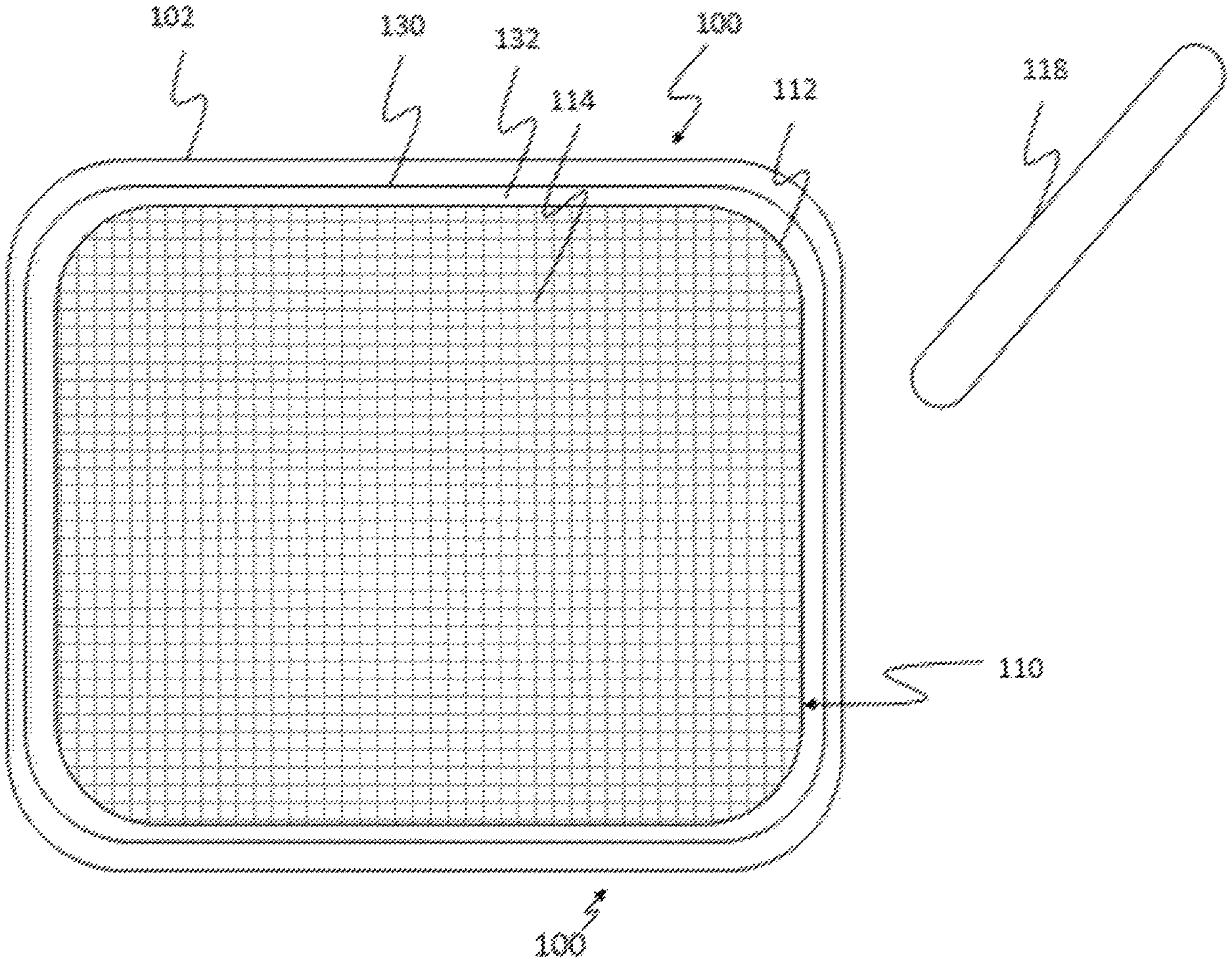
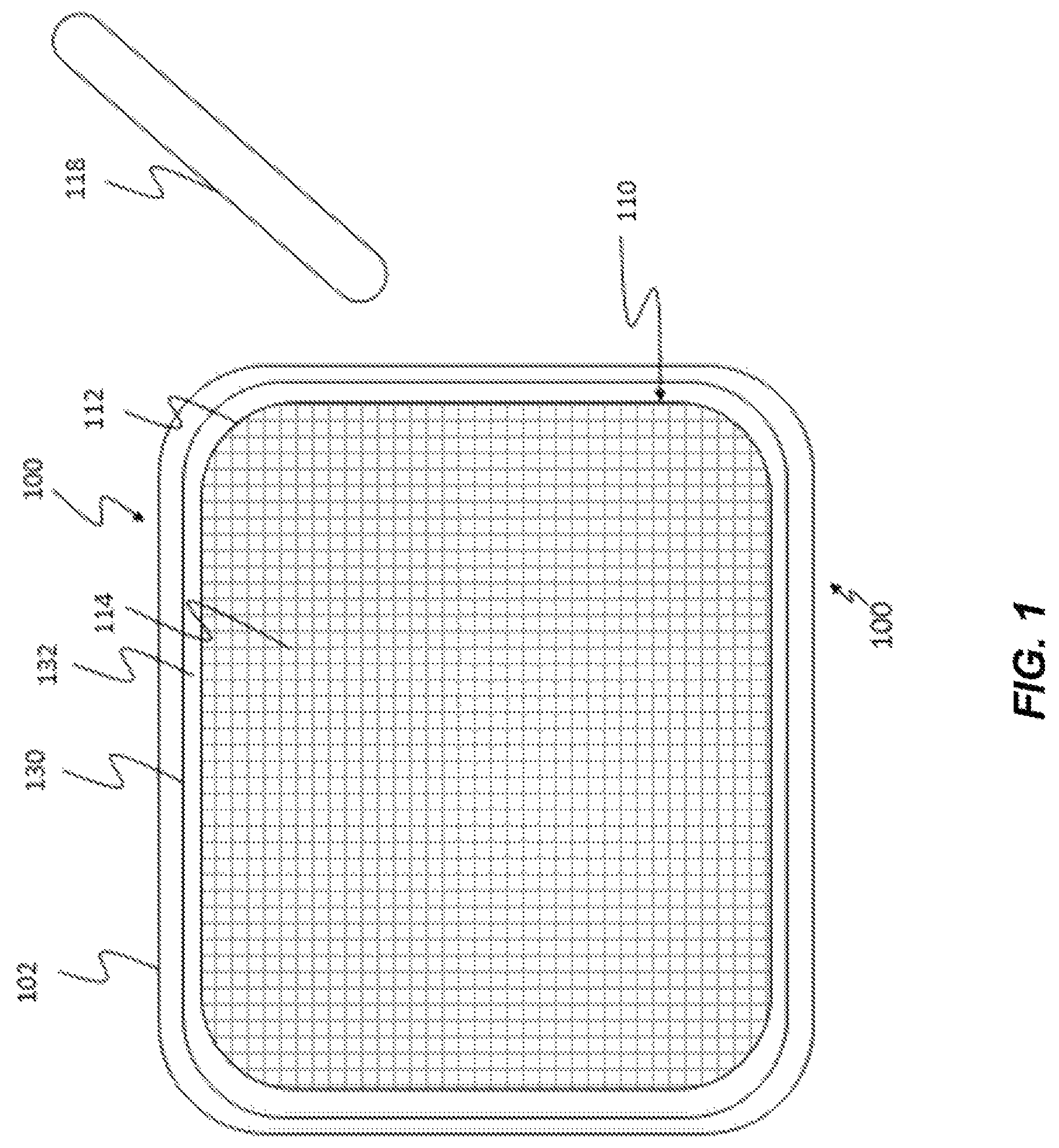
FIG. 1 illustrates an example touch sensing device having a touch sensitive surface, in accordance with some embodiments of the invention.
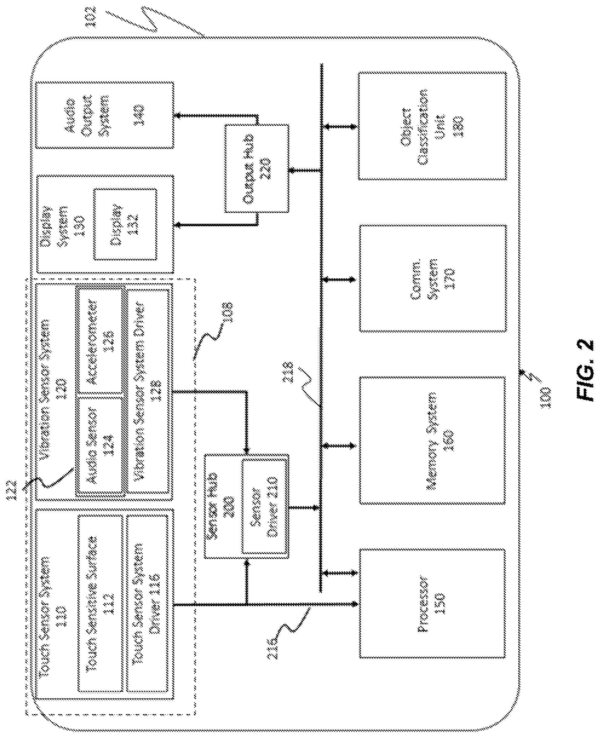
FIG. 2 illustrates an example touch sensitive device having a touch sensitive surface, in accordance with some embodiments of the invention.
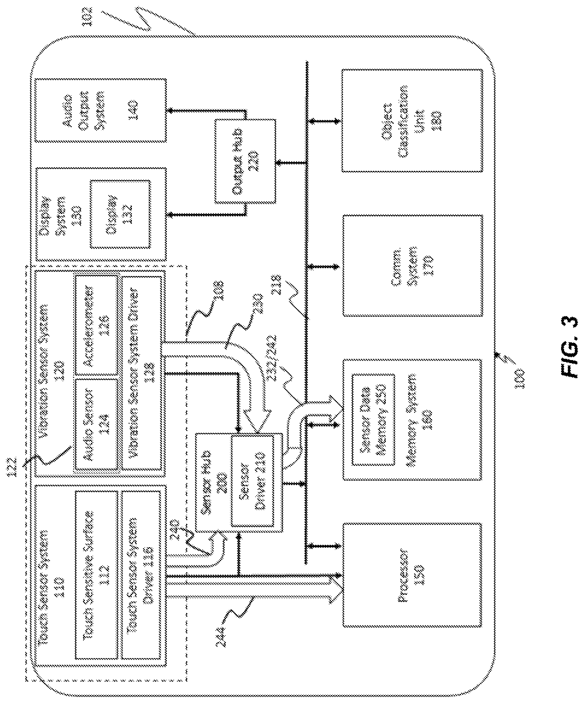
FIG. 3 illustrates an example of the touch sensitive device of FIG. 2 with data flows, in accordance with some embodiments of the invention.
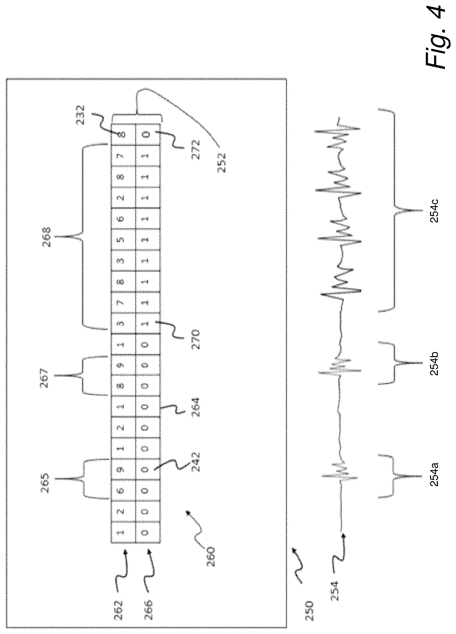
FIG. 4 illustrates an example of a sensor data memory and a vibrational stimulation, in accordance with some embodiments of the invention.
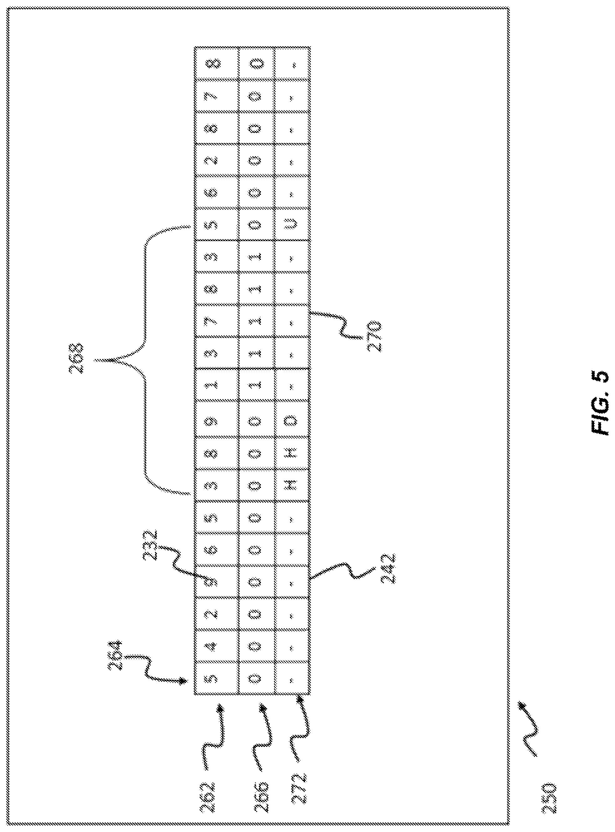
FIG. 5 illustrates another example of a sensor data memory, in accordance with some embodiments of the invention.
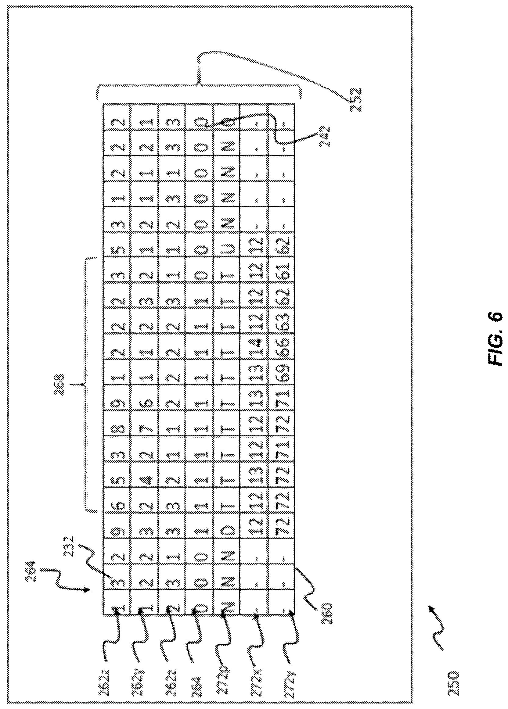
FIG. 6 illustrates another example of a sensor data memory, in accordance with some embodiments of the invention.
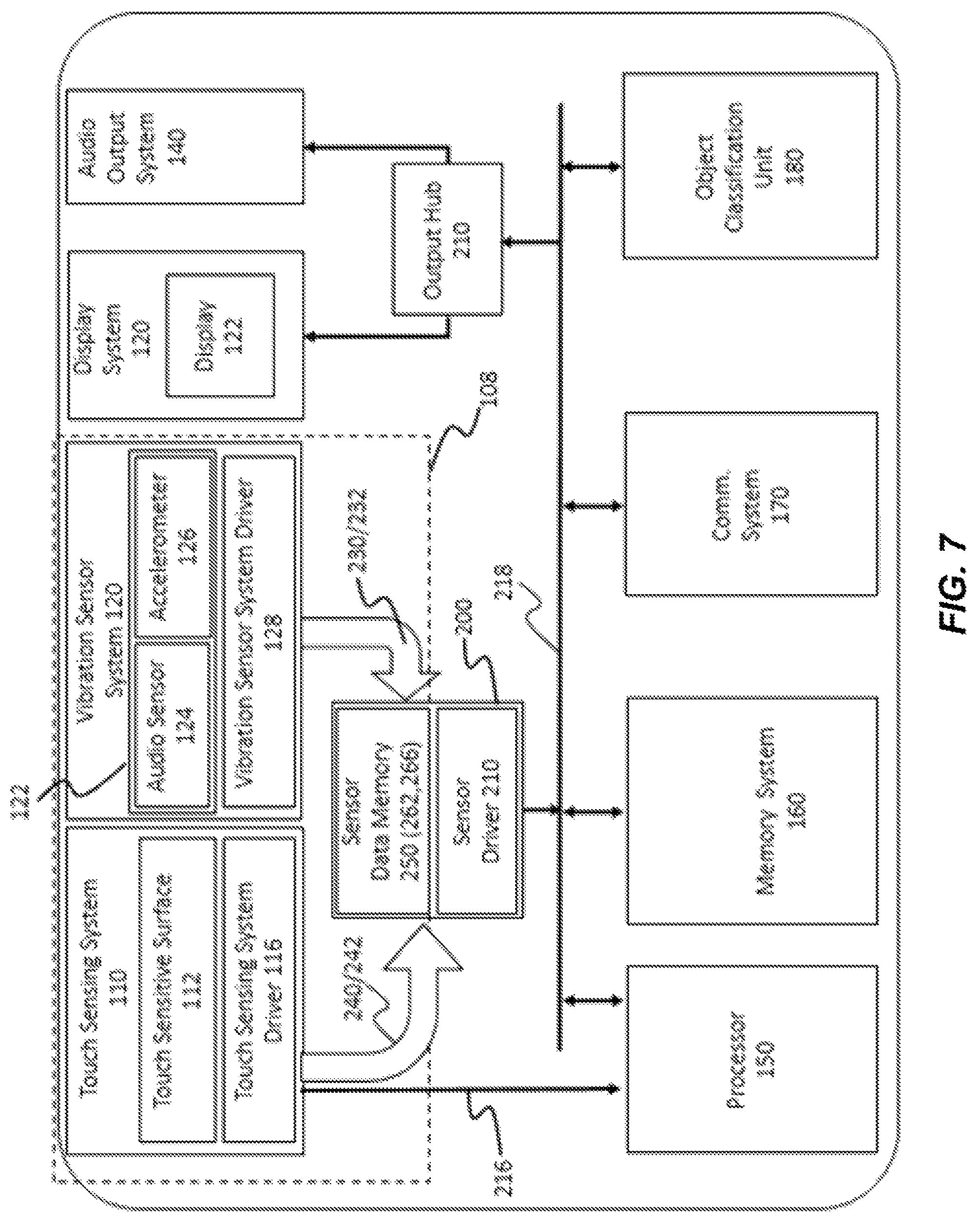
FIG. 7 illustrates another example of a touch sensitive device, in accordance with some embodiments of the invention.
FIG. 8 illustrates another example of a touch sensitive device, in accordance with some embodiments of the invention.
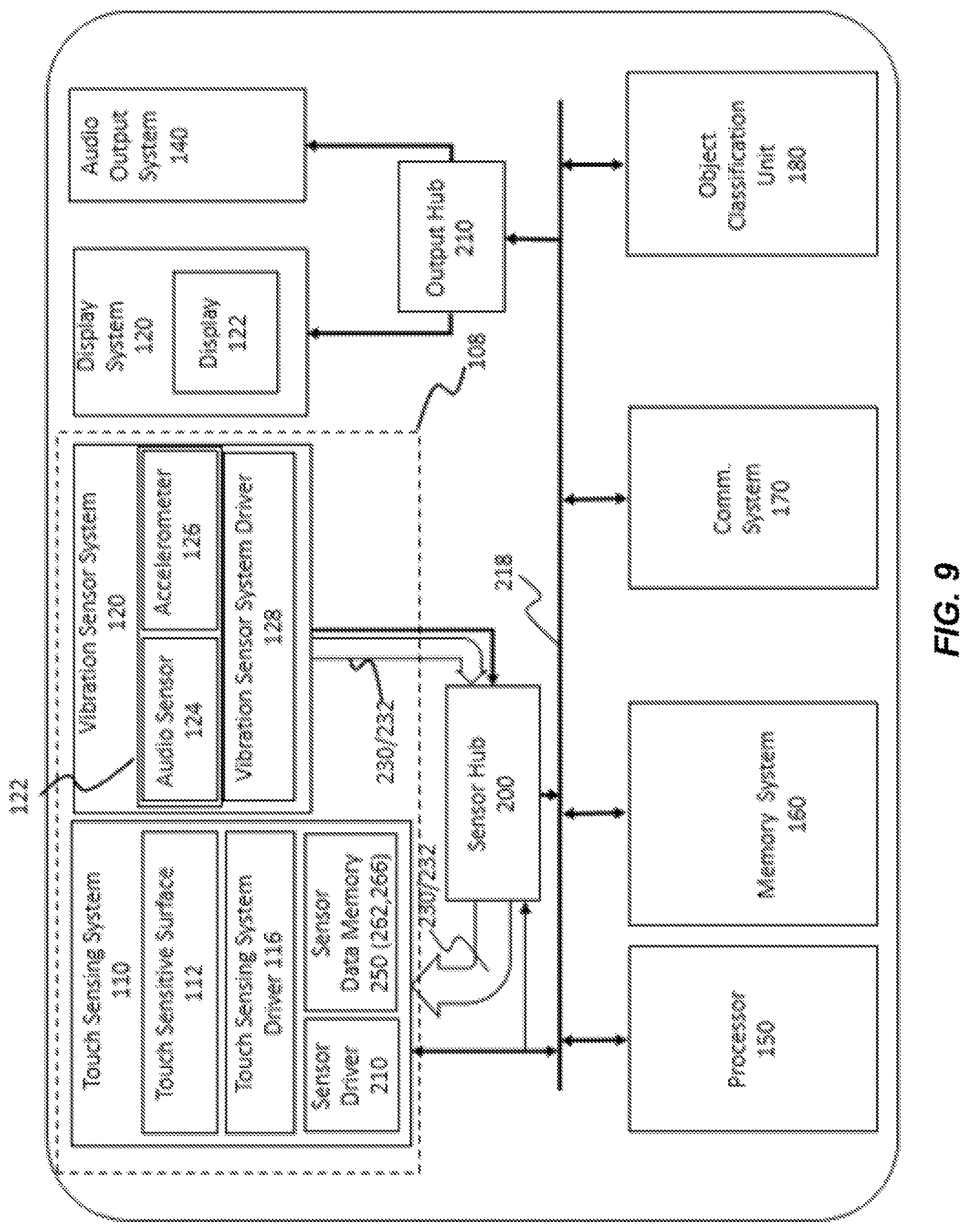
FIG. 9 illustrates another example of a touch sensitive device, in accordance with some embodiments of the invention.
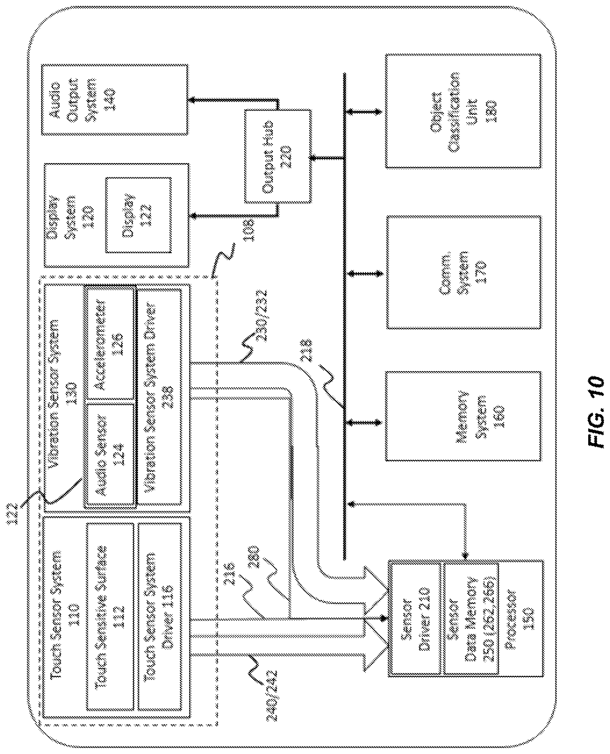
FIG. 10 illustrates another example of a touch sensitive device, in accordance with some embodiments of the invention.
DETAILED DESCRIPTION OF THE INVENTION
Applications of methods and apparatus according to one or more embodiments are described in this section. These examples are being provided solely to add context and aid in the understanding of the present disclosure. It will thus be apparent to one skilled in the art that the techniques described herein may be practiced without some or all of these specific details. In other instances, well known process steps have not been described in detail in order to avoid unnecessarily obscuring the present disclosure. Other applications are possible, such that the following examples should not be taken as definitive or limiting either in scope or setting.
In the following detailed description, references are made to the accompanying drawings, which form a part of the description and in which are shown, by way of illustration, specific embodiments. Although these embodiments are described in sufficient detail to enable one skilled in the art to practice the disclosure, it is understood that these examples are not limiting, such that other embodiments may be used and changes may be made without departing from the spirit and scope of the disclosure.
One or more embodiments may be implemented in numerous ways, including as a process, an apparatus, a system, a device, a method, a computer readable medium such as a computer readable storage medium containing computer readable instructions or computer program code, or as a computer program product comprising a computer usable medium having a computer readable program code embodied therein.
The figures in the following description relate to preferred embodiments by way of illustration only. The figures are not necessarily to scale. It should be noted that from the following discussion, alternative embodiments of the structures and methods disclosed herein will be readily recognized as viable alternatives that may be employed without departing from the principles of what is claimed.
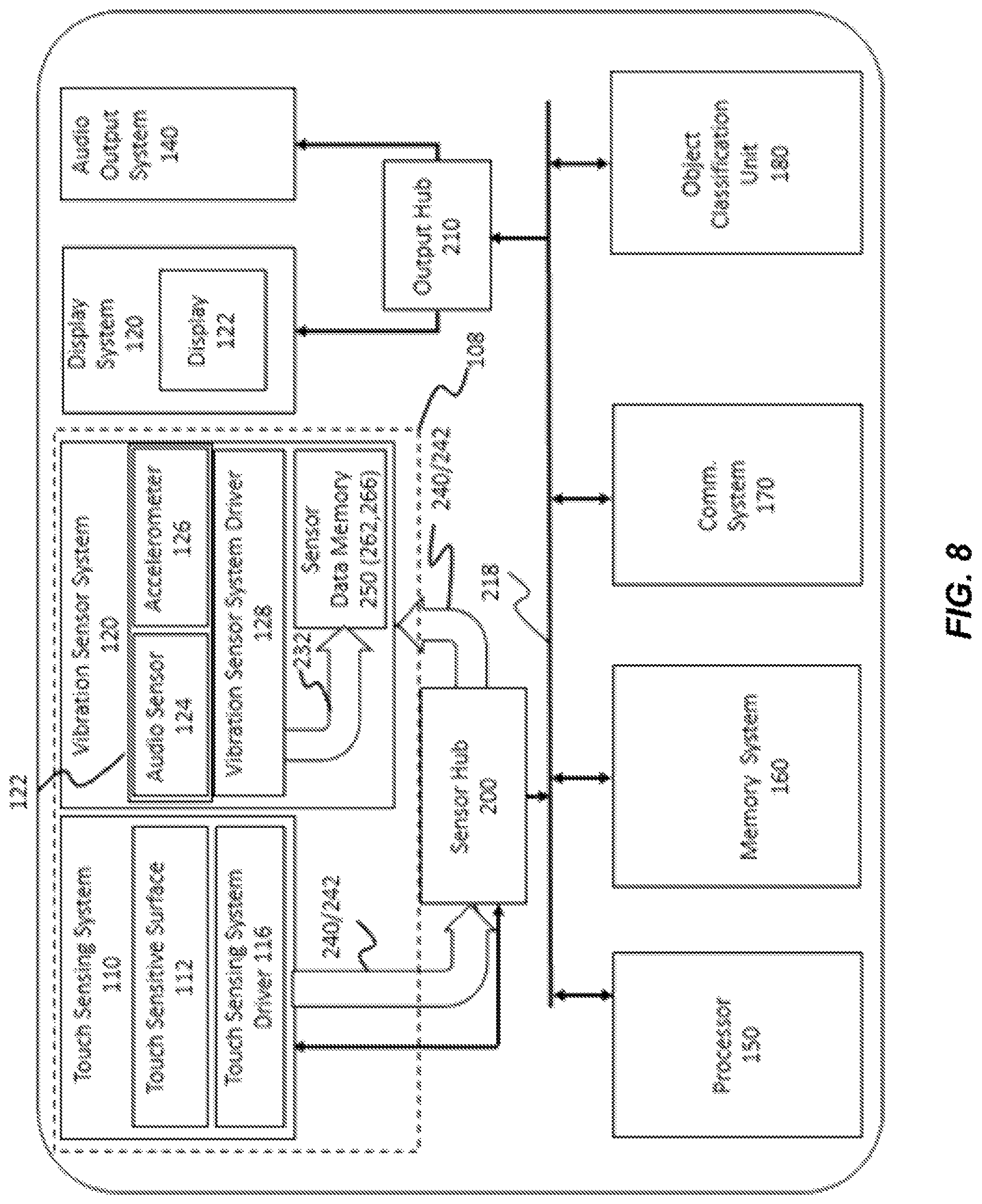
FIG. 1 illustrates an exterior view of one embodiment of a touch sensitive device 100 and FIG. 2 shows a block diagram of touch sensitive device 100. In this embodiment, touch sensitive device 100 takes the form of a touch sensitive cellular telephone having housing 102 holding a sensor system 108 with a touch sensor system 110 and a vibration sensing system 120, a display system 130, an audio output system 140, a processor 150, a memory system 160, a communication system 170 and an optional object classification unit 180.
As is shown in FIG. 2, in this embodiment, a sensor hub 200 has a sensor driver 210 that receives signals from sensor system 108 and makes information from the signals available to processor 150, memory system 160, communication system 170 and optional object classification unit 180 while an output hub 220 receives signals from processor 150 and provides signals to display system 130 and audio output system 160 in accordance with the signals received from processor 150 and a main bus 218 connects sensor hub 200, output hub 220, processor 150, memory system 160, communication system 170 and object classification unit 180. Direct connections between individual components can be made. For example, a direct connection 216 between touch sensor system 110 and processor 150 is shown in this embodiment.
Touch sensor system 110 has a touch sensitive surface 112 that is adapted to detect when an object 118 such as a fingertip, body part, or stylus is positioned in contact with touch sensitive surface 112 and to generate a signal from which it can be determined which portion of touch sensitive surface 112 is in contact with object 118.
In this embodiment, touch sensitive surface 112 has a plurality of touch sensing elements 114. Each of elements in the array of sensing elements 114 are associated with a predetermined portion of touch sensitive surface 112 and are capable of sensing contact with object 118. Sensing elements 114 can be of any known type. Common sensing elements can include capacitive sensing elements that detect changes in capacitance as an object approaches or contacts sensing elements 114 and resistive sensing elements that detect changes in resistance caused by contact between object 118 and touch sensitive surface 112. Any other type of sensing can be used for this purpose.
For convenience object 118 will be referred to herein in the singular form however, it will be appreciated that touch sensitive surface 112 may be of a "multi-touch" type that is capable of detecting when multiple objects 118 are in contact with touch sensitive surface 112.
In the embodiment that is illustrated in FIGS. 1 and 2, touch sensor system 110 has a touch sensor system driver 116 that sweeps array of sensing elements 114 or otherwise samples each element in array of sensing elements 114 to determine which portions of touch sensitive surface 102 were in contact with object in a given period of time. The period of time can be any period, however, for example and without limitation the period of time can be 1/30.sup.th, 1/60.sup.th or 1/100.sup.th of a second. Touch sensor signals are then generated from which it can be determined which portions of touch sensitive surface 112 were in contact with object 118 during the period of time. These signals can take the form of frame data that can be stored, for example, in digital form for use by other systems inside or outside of touch sensitive device 100. Touch sensor system driver 116 in some embodiments may generate other signals indicative of contact against touch sensitive surface 112 such as signals that are indicative of contacts between touch sensitive surface 114 during a sample. Touch sensor system 116 may also generate signals that are indicative of proximity of object 118 to touch sensitive surface 114 such as may occur when capacitive sensing elements are used for touch sensitive surface 112 as such touch sensitive elements can detect proximity prior of certain objects to touch sensitive surface 112 to contact. Other forms of proximity sensing may be used.
In this embodiment, touch sensitive device 100 further has a memory system 160. Memory system 160 is capable of storing frame data and may be capable of storing programs, executable algorithms, computer readable instructions or computer program code and other forms of instructions that can be executed by a processor 150 and may also be used for other purposes. Memory system 160 may include read only memory, random access semiconductor memory or other types of memory or computer readable media that may be permanently installed or separably mounted to touch sensitive device 100. Additionally, touch sensitive device 100 may also access a memory system 160 that is separate from touch sensitive device 100 by way of an optional communication system 170.
Processor 150 shown in the embodiment of FIGS. 1 and 2 can take the form of any device capable of performing the functions described herein including but not limited to a computer, micro-processor, micro-controller, programmable analog logic device, or a combination of devices and can be a stand-alone device or combination of devices.
Sensor system 108 can take any of a variety of forms and can comprise generally any known device for sensing conditions inside or outside of touch sensitive device 100. Sensor system 108 can, without limitation, include acoustic sensors, accelerometers, gyroscopes, light sensors, range finders, proximity sensors, barometer, touch input sensors, thermometers, Hall effect sensors, switches such as 2-way, 4-way switch, a 6-way switch, an 8-way switch, mouse and trackball systems, a joystick system, a voice recognition system, a video based gesture recognition system or other such systems, radio frequency identification and near field communication sensors, bar code sensors, position sensors and other sensors known in the art that can be used to detect conditions that may be useful to in governing operation of touch sensitive device 100 and to convert this information into a form that can be used by processor 140. Sensor system 108 may also include biometric sensors adapted to detect characteristics of a user that can be used, for example for security, medical and affective determinations.
Alternatively or additionally, vibration sensor system 120 can include vibration sensors, ultrasonic sensors, piezoelectric devices or other known circuits and systems that can sense vibrations such pressure waves carried by air surrounding touch sensitive system 100 such as acoustic signals or sounds, and/or acoustic signals that can carry mechanical vibrations carried through structures of touch sensitive device 100 or object 118 including but not limited to those that are indicative of contact between an object 118 and touch sensitive surface 112
Examples of sensor types that can be used to sense vibrations and that may be used as vibration sensors in a vibration sensor system 120 useful in operating a touch sensitive device include but are not limited to:
Piezoelectric bender elements;
Piezoelectric film;
Accelerometers (e.g., linear variable differential transformer (LVDT), Potentiometric, Variable Reluctance, Piezoelectric, Piezoresistive, Capacitive, Servo (Force Balance), MEMS);
Displacement sensors;
Velocity sensors;
Vibration sensors;
Gyroscopes;
Proximity Sensors;
Electric microphones;
Hydrophones;
Condenser microphones;
Electret condenser microphones;
Dynamic microphones;
Ribbon microphones;
Carbon microphones;
Piezoelectric microphones;
Fiber optic microphones;
Laser microphones;
Liquid microphones; and,
MEMS microphones
Optionally, both in-air vibrations or pressure waves and vibrations of components of touch sensitive device 100 can be sensed by vibration sensor system 120 (e.g., one for in-air acoustics, and one for mechanical vibrations, also referred to as structural acoustics). For example the embodiment illustrated in FIG. 2, touch sensitive device 100 has an audio sensor 124 for sensing in-air acoustics and an accelerometer 126 or sensing structural acoustics. Touch sensitive device 100 may use a sensing system 120 having a virtual or wireless connection to a microphone. In this embodiment, vibration sensing system 120 is also shown having an accelerometer 126.
It will be appreciated that many popular touch sensitive devices 100 such as cellular telephones and tablet computers are configured with both an audio sensor 124 and an accelerometer 126 for purposes such as voice communication and motion sensing. Such built in sensors can be utilized without the need for additional sensors, or can work in concert with sensors that are incorporated into touch sensitive device 100 primarily for the purpose of detecting conditions that may provide useful information in the interpretation of user input actions.
Vibration sensor system 120 can also include pressure sensors that can sense an amount of pressure applied by object 118 against touch sensitive surface 112. In some embodiments of this type touch sensitive surface 112 can be of a type that can sense not only which portion of touch sensitive surface 112 has been contacted by object 118 but the amount of pressure applied against touch sensitive surface. Various technologies of this type are known examples of which include, but are not limited to graphics tablets sold under the Wacom brand by Wacom Co., Ltd., Kazo, Saitama, Japan and that are presently capable of sensing 1024 different levels of pressure.
Optionally, vibration sensor system 120 can include one or more sensors that can be incorporated in or on object 118 and that can sense conditions indicative of an amount of force applied between object 118 and touch sensitive surface 112. In such embodiments, vibration sensor system 120 can include a force sensor that can take the form of, for example and without limitation, a piezoelectric sensor, a stress sensor, a strain sensor, a compression sensor, a deflection sensor, or resiliently biased sensing system that can sense force based on an extent of deflection movement of a contact surface against the force of the resilient member and that can generate a signal that is indicative of the amount of force applied by or through an indicator against touch sensitive surface 112.
A vibration sensor system 120 having a sensor in or on object 118 can send signals indicative of an amount of force between object 118 and touch sensitive surface 112 by way of a wired connection or a wireless connection such as by an optional wireless communication module that is capable of communication with communication system 170.
In further embodiments, force sensing can be achieved by providing an object 118 such as a stylus as illustrated in FIG. 1, that may in some embodiments have a rounded flexible tip such as a rubber or metallic mesh tip that are arranged in a resilient manner to flatten when pressed against touch sensitive surface 112 increasing the amount of surface area in contact with touch sensitive surface 112. In such embodiments, the size of the area in contact with touch sensitive surface 112 is an effective proxy for the amount of force applied by a user against touch sensitive surface 112 and in this regard a touch sensitive surface that is capable of sensing area that is in contact with touch sensitive surface 112 can be used for this purpose. Similar results can be achieved, with proper calibration, using a fingertip or other such object 118.
In the embodiment that is shown in FIG. 2, vibration sensor system 120 has a vibration sensor system driver 128 adapted to sample the sensors of vibration sensor system 120 during sensor sample periods and to generate vibration signals 230 that are indicative of conditions at the vibration sensor(s) during the vibration sensor sample periods. Vibration signals 230 can be in analog or digital form and may be processed, amplified, modulated, or otherwise adjusted by vibration sensor system driver 128.
Communication system 170 can take the form of any optical, radio frequency or other circuit or system that can convert data into a form that can be conveyed to an external device by way of an optical signal, radio frequency signal or other form of wired or wireless signal. Communication system 170 may be used for a variety of purposes including but not limited to sending and receiving instruction sets and exchanging data with remote sensors or memory systems.
Sensor hub 200 receives signals from touch sensor system 110 and vibration sensor system 120 makes these signals or data derived from these signals available to other components of touch sensitive device 100. In the embodiment that is illustrated in FIG. 2, sensor hub 200 is arranged to receive signals from touch sensor system 110 and vibration sensor system 120 and has a driver that prepares the signals for transmission through main bus 230 to other components of touch sensitive device 100. In other embodiments, sensor hub 200 can be connected directly to touch sensor system 110 and vibration sensor system 120 and to components of touch sensitive system 110 such as memory system 160, communication system 170 or on optional object classification unit 180.
Sensor hub 200 can optionally process signals received from touch sensor system 110 and vibration sensor system 120. For example and without limitation sensor hub 200 can optionally include analog to digital converters of any known type that can convert analog signals from vibration sensor system 120 into digital signals and may also include amplifiers, filters, including but not limited to noise filters, band pass/band reject filters or couplings, breakers, fusible links or other systems that protect other components of touch sensitive system 100 from potential damage.
Sensor hub 200, according to one embodiment, may perform a function of interfacing with sensing system 108 to sense a sound or vibration generated when object 118 contacts touch sensitive surface 112, or, in other embodiments, other specific parts (i.e., the exterior parts) of touch sensitive device 100.
Output hub 220 is optional and in this embodiment receives signals from processor 150 and optionally other components of touch sensitive system 100 and may use these signals to control operation of display system 130 and audio output system 140 as well as any other output systems that may be incorporated into touch sensitive system. In this regard, output hub 220 may include display drivers, audio output systems including amplifiers and the like.
It will be appreciated that various embodiments of the invention, some or all of the functions ascribed to output hub 220 may be performed by hardware or programs that are integrated in whole or in part in touch sensor system 110 and vibration sensing system 120 including but not limited to touch sensor system driver 116 and vibration sensor system driver 128.
Contact Interpretation
The task of deriving information from contacts between touch sensitive device 100 and an object 118 can be daunting given the challenge of providing a near instantaneous response to such input and the challenge of ensuring that the input is properly understood. In particular it will be understood that not all contacts against a touch sensitive surface 112 are intended as an input. Incidental contacts and other contacts against touch sensitive surface 112 occur frequently and if interpreted in the same manner as intentional contacts these may cause unintended consequences.
Further, input made using touch sensitive surfaces 112 can be complex. For example, such input can take the form of a stroke type input such as signatures, artistic renderings, as well as common file and data manipulations such as cut and paste manipulations. These inputs may range over a wide portion of the input screen and may occur over a relatively extended time period. Depending on the rate at which frame data is obtained, it may be necessary for processor 140 to evaluate many thousands of frames of data to determine stroke data associated with a single stroke and in the case of multi-point touch sensitive systems it may be necessary to track many contact points across these many frames. This makes interpretation of such input a processor intensive task.
Additionally, there is a wealth of additional information that the touch sensitive device can provide to processor 140 that may be highly beneficial to processor 140 in making determinations regarding the intent of the user in bringing an object 118 into contact with touch sensitive surface 112.
For example, a touch sensitive device 100 having a touch sensor system 108 with a vibration sensor system 120 such as the one that is illustrated in FIGS. 1 and 2 may be capable of sensing vibrations carried to vibration sensor system 120 through elements of touch sensitive device 100 or vibrations carried to vibration sensing system 120 by way of a medium surrounding touch sensitive device 100 such as acoustic vibrations carried in air or water. Vibration sensor system 120 has at least one vibration sensor that senses the vibrations and provides a vibration signal that is indicative of the sensed vibrations. Optionally, vibration sensor system 120 may have a vibration sensor system driver 128 that amplifies, powers, filters or otherwise prepares the vibration signal for use by processor 150 or sensor hub 200. In some embodiments vibration sensing system 120 may provide vibration signals in analog form for conversion to digital form by another device such as by way of a sensor hub 200. Vibration sensor system sensor driver 128 may perform other functions as described or claimed herein.
The vibration signal is used by processor 150 determine vibro-acoustic information that can be used during analysis of a touch event. For example, the vibration signal may yield vibro-acoustic information such as the magnitude of the amplitude of the vibrations occurring incident to a contact between an object 118 and touch sensitive surface 112 signal. However, this is not limiting and processor 150 may use any type of statistical, mathematical, or other logical analysis of the vibration signal to determine vibration information that may be useful in operating touch sensitive device 100. The use of the term vibro-acoustic information may encompass any information derivable from vibrations sensed incident to a touch event and may include either or both of information derived from vibrations carried in touch sensitive device 100 to a sensor or vibrations carried to a sensor by way of an intermediate medium such as acoustic vibrations carried in the form of air pressure variations, as well as information sensed in any other manner including but not limited to vibration information sensed by touch sensor system 110 and vibration information sensed by external devices.
Such vibro-acoustic information may be useful to help processor 150 to determine the nature of an object that has made contact with touch sensitive surface 112. One method for doing this is described in commonly assigned and co-pending U.S. patent application Ser. No. 14/612,089, entitled "Method and Apparatus for Classifying Finger Touch Events on a Touch Screen," filed on Feb. 2, 2015, and incorporated by reference herein in its entirety. This application in part describes an apparatus for classifying touch events having a touch sensitive surface configured to generate a touch event when an object or finger touches the touch sensitive surface, wherein the touch event entails a mechanical vibration generated upon contact with the surface, a touch detector configured to detect the onset of a touch and a touch event classifier configured to classify the touch event to identify the object used for the touch event.
Vibro-acoustic information may also be used as described in commonly assigned and co-pending "Capture of Vibro-Acoustic Data used to Determine Touch Types, U.S. patent application Ser. No. 13/958,427 filed on Aug. 2, 2013 and incorporated herein by reference in its entirety. This application describes in part a method for interaction between a user and an electronic device having a touch sensitive surface. In this method a touch event trigger is received that indicates an occurrence of a physical touch event on the touch-sensitive surface. Touch data produced by the touch event is accessed and vibro-acoustic data for a vibro-acoustic signal produced by the physical touch event is accessed for a time window that begins at a time that is prior to receipt of the touch event trigger and a touch type for the touch event is determined based on the touch data and the vibro-acoustic data.
Vibro-acoustic data also may be used as is described in commonly assigned and co-pending U.S. patent application Ser. No. 14/219,919, entitled "Method and Device for Sensing Touch Inputs", filed on Mar. 19, 2014 and incorporated herein by reference in its entirety. This application describes in part, a method for sensing touch inputs to digital equipment in which a sound/vibration signal that is generated by a touch is sensed and the sensed sound/vibration signal is digitally processed. Here the type of touch means as well as a touch intensity is determined based on features derived from time and frequency domain representations of the processed sound/vibration signal.
Additionally, there are vibro-acoustic differences between contact made with a sensing surface when different parts of a input tool contact a touch sensitive surface. These differences are usefully applied in commonly assigned and co-pending U.S. patent application Ser. No. 14/668,870, entitled "Input Tools Having Vibro-Acoustically Distinct Regions and Computing Device For Use With Same," filed on Mar. 25, 2015 and incorporated herein by reference in its entirety. This application describes in part an input tool for interacting with a touch screen, the input tool comprising: a body in the form of a stylus, the body having one or more vibro-acoustically distinct regions, wherein each virbo-acoustically region produces a discrete vibro-acoustic signal when it touches a surface of the touch screen and the virbo-acoustic signal is used to detect what region of the input tool was used. Such vibro-acoustic signals can also be used to discriminate between different types of finger contacts such as contact with the knuckle, fingernail and fingertip as is described in commonly assigned U.S. Pat. No. 9,013,452, entitled "Method and System For Activating Different Interactive Functions Using Different Types of Finger Contact", filed on Mar. 25, 2013 and issued on Apr. 21, 2015 and incorporated by reference in its entirety.
Virbro-acoustic information may also be used to determine which portions of a finger have contacted touch sensitive surface 112 and may for example result in execution of a first action for a first finger touch type and a second action for a second finger touch type. For example, U.S. patent application Ser. No. 13/887,711 entitled "Using Finger Touch Types to Interact with Electronic Devices", filed on May 6, 2013 and incorporated by reference in its entirety describes such an application.
Capacitive data can also provide data that can be useful in analyzing contacts with a touch sensitive surface 112. For example in commonly assigned and co-pending U.S. patent application Ser. No. 14/191,329, entitled "Using Capacitive Images for Touch Type Classification," filed on Feb. 26, 2014, describes in part a method of interaction between a user and an electronic device having a touch sensitive surface. In one aspect of this, a capacitive image is accessed comprising capacitive image data corresponding to capacitances at a plurality of locations on the touch-sensitive surface, the capacitances varying in response to a physical touch on the touch-sensitive surface The capacitive image data is processed and it may be possible to determine a touch type for the physical touch based on the processed capacitive image data. It may also be useful to, where possible to do so, maintain heuristic data regarding such objects.
Touch intensity data can also provide information that can be useful to processor 150 in determining how to react to a touch contact. Such touch intensity data can be determined based upon the touch intensity between object 118 and touch sensitive surface 112 which in turn can be determined for example based upon capacitance, resistance or shear force measurements. Additionally, touch intensity data can be determined based upon sensed variations in an amount of force applied through indicator 130 against touch sensitive surface 112 which can be sensed in the various ways described in greater detail above and in any other know manners for sensing force applied against a surface.
In the embodiment of FIGS. 1 and 2 an object classification unit 180 is provided that can be used to determine object characterization information. Furthermore, object classification unit 180 may transmit contact intensity data characterizing an amount of force applied by or through object 118 during contact. This can be done in one embodiment by providing touch intensity data that corresponds to each element of touch intensity data or by sampling, mathematically processing or otherwise processing force data to characterize the amount of force applied during a frame. Such information can be used by processor 150 in understanding the proper response to contact with an object 118.
It will be understood that operating processor 150 in a manner that continuously monitors frame data from touch sensor system 110 while simultaneously operating processor 150 to monitor and analyze signals from vibration sensor system 120 in real time creates a significant burden on the processor 150 that can make the processor 150 perform functions more slowly and that can reduce the efficiency of processor 150 and, where a portable power supply is used this can have the effect of lowering the run time between charging.
An alternative option of initiating sampling of audio sensor 124 or an accelerometer 126 only after contact is sensed by a touch sensitive surface 112 risks creating conditions where important components of the vibro-acoustic, capacitance and touch intensity patterns are not captured. This limits the usefulness of the information captured after touch is detected.
What is needed therefore is a way to allow touch sensitive device 100 to make vibration data representing conditions that are sensed by vibration sensor system 100 available to processor 150 when needed while enabling processor 150 to operate effectively and efficiently.
FIG. 3 shows one embodiment of touch sensor system 110 that allows desired information captured by vibration sensor system 120 to be preserved and available while allowing efficient use of processor 150. In the embodiment of FIG. 3, sensor hub 200 receives vibration signals 230 from vibration sensor system 120 that are representative of conditions that are incidental to contact between touch sensor system 100 and object 118. In this embodiment, vibration sensor system 120 has a vibration sensor 122 that includes an audio sensor 124, such as a microphone that senses acoustic signals that are representative of vibrations or pressure changes carried by air or any other medium within which touch sensitive device 110 is operated and an accelerometer 126 that is used to sense vibrational signals carried through touch sensitive device 100. In this embodiment, signals from audio sensor 124 and accelerometer 126 are received by vibration sensor system driver 128 which provides a vibration signal 230 to sensor hub 200 and in this embodiment sensor diver 210. One or both of vibration sensor system driver 128 and a sensor driver 210 shown in this embodiment as being in sensor hub 200 can optionally be used to perform any desired processing or organization of vibration signal 230. Sensor driver 210 causes vibration data 232 to be stored in a sensor data memory 250 which in the embodiment illustrated in FIG. 3 is located in memory system 160. Vibration data 232 may also include any other data or metadata associated with vibration data 232 as well as any other data detected by vibration sensor system 120 or otherwise provided by vibration system driver 128. Vibration data 232 may also include other data determined or derived by sensor driver 210 based upon conditions that are sensed by vibration sensor system 120 or otherwise included in vibration signal 230.
Touch sensor system 110 has a touch sensor system driver 116 that generates touch sensor system signals 240 and frame data 244 based upon conditions sensed at touch sensitive surface 112. Frame data 244 travels to processor 150 for analysis while touch signals 240 are directed to sensor driver 210. Such touch signals 240 include signals that sensor driver 210 can use to determine the presence or absence of any touch against touch sensitive surface 112. Sensor driver 210 performs any desired processing of touch sensor system signals 240 and provides touch data 242 which includes data indicative of touch sensing events including but not limited to times at which contact between touch sensitive surface 112 and an object 118 occurs. In one non-limiting example of this sensor driver 210 provides touch data 242 having indicating whether or not touch sensor signal 240 indicates that there is contact between touch sensitive surface 112 and an object 118. For example, where no contact exists touch data 242 may have a value of 0 and where contact exists the touch data may have a value of 1. Touch data 242 may also include or be based upon frame data 244 and any metadata associated with frame data 244 as well as any other data detected by touch sensor system 110 or otherwise provided by touch sensor system driver 116. Touch data 242 may also include other data determined or derived by sensor driver 210 based upon conditions that are sensed by touch sensor system 110 or otherwise included in touch sensor system signal 240.
In other embodiments, touch sensor system 110 may capable of detecting when an object 118 is within a range of non-touching positions proximate to touch sensitive surface 112 and may include signals indicating the proximate presence of the non-touching object 118. Such a touch sensor system 110 may provide touch sensor system signals 240 including signals from which sensor data driver 210 can determine when an object 118 such as a finger, is hovering within the range of non-contact positions proximate to touch sensitive surface 112 in which object 118 can be detected. In this manner, sensor data driver 210 can provide touch data 242 indicating when object 118 is approaching contact with touch sensitive surface 112, lifts from contact with surface 112 or otherwise changes position within the range of non-touching positions.
In operation, a controller shown here as sensor driver 210 causes touch data 242 to be stored in temporal association with vibration data 232 in a sensor data memory 250. At an initial level, this relieves processor 150 from having to directly process and manage the storage of touch data 242 while preserving such information for use by processor 150 when desired. This may be used, for example, to allow processor 150 to determine whether, for example, data extracted from ongoing analysis of frame data 244 provides sufficient information to make confident decisions about actions that processor 150 is to undertake. Where this data does not provide sufficient information or where processor 150 determines that such information may be otherwise useful, processor 150 can supplement decision making processes by way of analysis of vibration data 232.
Accordingly, it will be understood that having vibration data 232 available to processor 150 is particularly valuable when necessary. However, in the management of a touch sensitive device 100 it is also particularly valuable that relevant portions of vibration data 232 be accessible to processor 150 in a rapid and efficient fashion.
The temporal association between vibration data 230 and touch data 246 with touch events makes it possible for processor 150 to identify and examine relevant portions of sensor system data with the desired rapidity and efficiency. For example, it will be understood that when a signal from audio sensor 124 or accelerometer 126 is useful for classifying the touch type (i.e., touch means), vibration data 232 sampled immediately around and after the touch down event is typically of greatest interest. Accordingly, by maintaining vibration data 232 that is in some type of logical association with touch data 242 that indicates a temporal association between vibration data 232 and touch data 242 data is preserved in a manner that can be quickly accessed by processor 150 and efficiently used to identify one or more segments of vibration data 232 of interest at a particular time. Any stored vibration data 232 that is not temporally stored in association with touch data 242 related to a touch event of interest can be ignored, discarded, overwritten or used for other purposes if appropriate.
FIG. 4 illustrates a first example of the contents of a sensor data memory 250 in which sensor data 252 including vibration data 232 and touch data 242 is organized into a data structure 260. In this embodiment, sensor data structure 260 stores sensor data 252 in sequential manner using, as illustrated here a series of samples arranged from oldest in time to newest. In this regard sensor data memory 250 can use a First-In-First Out (FIFO) data storage approach or in a First-In-Last-Out (FILO) data storage. Other approaches are possible and these include, but are not limited to, overwriting the oldest sensor data 252 in the sequential data record with the newest sensor data 252 and so that data in the sequential data record is recorded in a circular and continuous fashion. Sequential data structure 260 may also operate as a buffer that simply that stops recording data when out of memory or that erases sensor data 252 at device or session shutdowns or restarts or when modes or application programs are changed. Although data structure 260 is illustrated as a sequential data structure in this embodiment, other known logical data structures may be used so long as a temporal association between vibration data 232 and touch data 242 is maintained.
In this example data structure 260 has a vibration data record 262 with a sequence of numbers representing vibration data 232 sampled during a sequence of sample periods 264 and a touch data record 266 including touch data 242 for each of sample periods 264. In this way, a temporal association is provided between vibration data 232 and touch data 242 within each sample period 264. Other arrangements can be used.
In operation, processor 150 can identify a relevant segment of vibration data record 262 by locating transitions in the state of touch data record 266. For example, in the embodiment illustrated in FIG. 4, processor 150 can determine that segment 268 of vibration data record 262 has data that is of potential interest by locating the transition from a value of 0 (representing for example no object in contact with touch sensitive surface) to 1 (representing for example an indication that an object is in contact with touch sensitive surface) in the touch data record 266 and by initiating analysis of data from vibration data record 262 beginning with data from vibration data record 262 that is associated with or located based upon a detected transition in touch data record 266. This, in turn, allows processor 150 to ignore vibration data 232 in portions of vibration data record 262 that are outside of segment 268.
In the example shown in FIG. 4, a vibrational stimulation 254 of vibration sensor system 120 is illustrated as an analog waveform that is associated in time with vibration data 232 and touch data 242. In FIG. 4, vibration data 232 is representative of vibration sensed by vibration sensor system 120 in response to vibrational stimulation 254. As can be seen in FIG. 4 single channel vibration signal 254 has three portions 254a, 254b and 254c where vibrations are sensed that are above a general baseline and vibration data record 262 has vibration data with three different segments 265, 267, and 268 with data that reflects these conditions. If asked to analyze such vibration data 232, processor 150 would have to perform significant processing to determine which of segments 265, 267 and 268 is a segment of interest in making operating decisions. This is time consuming, processor cycle consuming, power consuming and can lead to errors.
However, as is shown in FIG. 4, in this embodiment touch data 242 occurring during vibrational stimulation 254 is also stored in temporal association vibration data 232. For the purposes of this example, touch data 242 is illustrated as a single channel of data with a 0 being indicative of a time where no contact is sensed between touch sensitive surface 112 and an object 118 and with a 1 representing a time at which contact between touch sensitive surface 112 and an object 118 is sensed.
This arrangement allows processor 150 to examine touch data record 266 to determine which portions of touch data 242 in touch data record 266 are indicative of a touch contact with touch sensitive surface 110. Once that touch data 242 indicative of such touch contact is found, processor 150 can use the temporal association between the determined touch data 242 and vibration data 232 to identify a segment of vibration data record 262 that is of interest.
In the example of FIG. 4, processor 140 can begin analysis of sensor data 252 by analyzing touch data 242 in touch record 266 at a time that is known to be before the time of the touch contact that is being analyzed. In this example, processor 150 can quickly determine that the vibration data 232 in segments 265 and 267 are not related to the touch event of interest in that portions 265 and 267 of vibration data record 262 were obtained at a time that touch sensitive surface 112 was not in contact with object 118 and can perform analysis on segment 268.
In FIG. 4, segment 268 is shown beginning with vibration data 232 that is temporally associated with a transition of touch data 242 from data that indicates no contact between touch sensitive surface 112 and object 118 to a data that indicates that contact between touch sensitive surface 112 and object 118. Here this is illustrated by a transition between touch data having a value of 0 to touch data 232 having a value of 1. Similarly segment 268 ends with vibration data 232 that is temporally associated with a transition of touch data 242 from data that indicates contact between touch sensitive surface 112 and object 118 to a data that indicates that no contact between touch sensitive surface 112 and object 118. Here this is illustrated by a transition between touch data having a value 1 to touch data 232 having a value of 0.
This is not the only approach that can be used for this purpose. In other embodiments, processor 150 may define a segment vibration data 232 for consideration to include, for example and, without limitation, a predetermined extent of vibration data 232 following the occurrence of a transition in the touch data record 264. In other non-limiting alternatives the extent of the vibration data record 262 considered by processor 150 may be variable and may continue until processor 150 has received sufficient information to make particular determinations such as, for example, determinations classifying contacts against touch sensitive surface 112. In such an example, processor 150 can determine to end segment 268 when processor 150 reaches a determination that classifies a contact, a determination that vibration data 232 data does not support a particular classification for the contact or as illustrated here, when an indication of contact with a touch sensitive screen is no longer present. Other criteria can be used for determining the end of a segment of interest 268.
Similarly, it will be appreciated that the start of a segment of interest 268 may begin with vibration data 232 that is associated with sample periods 266 other than an individual one that is associated with a transition in touch data 242 in the touch event data record 266. For example, and without limitation there may be a phase or sampling period difference between vibration data 232 in vibration data record 262 and touch data 242 in touch data record 264. In such cases, or for other reasons, processor 150 therefore may determine the start of a segment 268 of vibration data 232 based upon a detected transition in the touch data record 264 but may include vibration data 232 from sample periods 266 beginning either before or after a change in the touch data 242 in the touch data record 264.
It will be appreciated that vibration data 232 illustrated in vibration data record 262 and touch data 242 illustrated in touch data record 264 in FIG. 4 are for the purpose of illustration and explanation only and are not limiting. For example and without limitation, vibration data record 262 may include any types of data obtainable by sensing system 130, including processed forms of such data, combinations, calculations made using such data and derivatives thereof. Similarly, touch data record 264 may include without limitation touch data 232 that characterizes or that can be used to determine characteristics of any of the following information:
Event type (e.g., hover/proximate finger, no object, touching object, multiple objects)
X/Y coordinates of any fingers on the screen;
orientation of any fingers on the screen;
first and second moments of any touch blobs (fingers) on the screen;
pressure of any fingers on the screen;
raw capacitive image of the touchscreen; and/or
a filtered/processed capacitive image of the touchscreen
and may also include processed forms of such data, combinations, calculations made using such data and derivatives thereof.
Processor 150 can use data stored in sensor data memory 250 to trigger different behaviors in order to better optimize operation of touch sensitive device 100.
The use of the sequential data structure 260 as illustrated is optional and any data configuration or algorithmic or other logical organization allows storage of sensor data 262 which, that includes data characterizing vibrations sensed during a plurality of sequential sample periods along with some form of a logical association between touch data 264 and vibration data 232 such that the touch data can be used to identify a segment of vibration data 232 that may have been sensed at a time of contact between an object 118 and touch sensitive surface 112.
FIG. 5 illustrates a sensor data memory 250 having another embodiment of a sensor data record 252 that may be used in conjunction a touch sensitive device such as touch sensitive device 100 of FIGS. 1-3. However, in this embodiment, touch sensitive device 100 is capable of sensing when a finger or other object 118 is positioned within a range of non-contact positions that are proximate to touch sensitive surface 112. In one embodiment, this can be done, for example, using an array of sensing elements 114 that are capable of sensing capacitance changes as a finger or other object is brought closer to touch sensitive surface 112. In other embodiments, other sensors such as infrared or visible light sensors or imagers can be used for this purpose.
In this embodiment, a sequential data structure 260 is used that stores vibration data 232 and touch data 242 that may be generated when touch sensor system 110 shown above is capable of sensing when an object 118 such as a finger is positioned proximate to but not in contact with touch sensitive surface 114. As is illustrated in FIG. 5, in this embodiment, sequential data structure 260 takes the form of a supplemental touch data record 272. Proximity data record 272 includes three different entries, an "H" data point indicating that an object 118 such as a finger is within a range of sensing positions relative to touch sensitive surface 112 and is maintaining a distance from touch sensitive surface 112 but has not contacted touch sensitive surface 112, a "D" data point indicating object 118 is moving toward touch sensitive surface and a "U" data point indicating that object 118 has broken contact with touch sensitive surface 112 and is moving away. Processor 150 can therefore use the "D" data point in this embodiment in identifying when to begin segment 268 or as is shown in FIG. 6, by beginning segment 268 based upon the "H" data point, it becomes possible to define segment 268 to include sensing signal data 232 for sample periods 264 that begin as or just before a vibrational/acoustic signal 252 created by contact between touch sensitive surface 112 and object 118 begins. This can be used to provide one or more of the advantages described above.
Optionally, in such an embodiment, upon detection of a hover/or downward finger event, components of vibration sensor system 120 such as audio sensor 124 and/or accelerometer 126 can be turned on, or put into a high speed/high fidelity mode. Conversely, when an object is lifted from contact with touch sensitive surface or sensed moving away from touch sensitive surface 112 ("touch up event"), audio sensor 124 accelerometer 126 can be turned off, put into a low power mode, put into a low speed/low fidelity mode. This advantageously reduces power consumption and memory requirements.
FIG. 6 shows a sensor data memory 250 having another embodiment of a sequential data structure 260. In this embodiment both touch data record 242 having touch data 232 stored therein and a supplemental touch data record 272 is used to record any other information obtained by sensor system 108 regarding the proximity of an object 118 to touch sensitive surface 112 or contact between object 118 and touch sensitive surface 112. Without limitation supplemental touch data record 272 can include as illustrated, separate records with touch data 232 in a touch data record 264, a proximity data record 2'72p, an x-axis data record having data indicating an x-axis position of the detected contact 272x, and a y-axis data record having data indicating a y-axis position of the detected contact 272y. The x-axis data 272x and y-axis data 272y indicate a coordinate of contact between object 118 and a touch sensitive surface 114 and, optionally, can be used to indicate a coordinate of any sensed proximity.
As is also shown in FIG. 6, vibration data 262 may include data that is in one or more axis such as where audio sensors are made directional or where three axis sensors are used to sense vibration. In the example shown in FIG. 6, data from a three axis sensor is organized into an x-axis vibration data record 262x, a y-axis vibration data record 262y, and a z-axis vibration data record 262z. Here all are shown in temporal association with touch data in touch records 272t, 272p, 272x, and 272y. However, in other embodiments a temporal association may be necessarily maintained between two of these data records with other portions of such records used for other purposes by processor 150.
It will be appreciated from FIG. 6, that other types and kinds of data and metadata and data derived from either of vibration signals 230 and touch signals 240 and from other sources can be stored in memory 150 optionally in temporal association and that the records illustrated in FIG. 6 are exemplary and not limiting.
In the embodiment of FIGS. 1-3, sensor data memory 250 is illustrated being located in memory system 160. However, in other embodiments, sensor data memory 250 can be located in other portions of a touch sensitive device 100. For example, in the embodiment illustrated in FIG. 7, sensor data memory 250 is illustrated as being located in sensor hub 200. This advantageously allows vibration signals 230 as well as touch sensor system signals 240 to pass to sensor hub 200 where sensor driver 210 can convert these as necessary into vibration data 232 and touch data 242 for storage as vibration data record 262 and touch data record 266 in sensor data memory 250 without burdening main bus 218 with high speed data flows.
In still another embodiment illustrated in FIG. 8, sensor data memory 250 is located in vibration sensor system 120 with touch sensor system signals 240 or touch sensor signal data 242 passing to sensor hub 200 and with touch sensor system signals 240 or touch data 242 then being passed along to vibration sensor system 120 for storage in sensor data memory 250 in temporal association with vibration data 232. Touch sensor system signals 240 or touch sensor signal data 242 can be further processed by vibration sensor system driver 128 or sensor hub 200 before storage in sensor data memory 250. Such processing can include for example and without limitation converting touch sensor system signals 240 into touch sensor signal data 242, using touch sensor signal data 242 to create a touch data record, or creating a temporal association between vibration data record 262 and touch data record 266. This embodiment allows the use of memory circuits (not shown) that may be available in vibration sensor system 120 and optionally can also leverage other capabilities of components of vibration sensor system 120. Similarly, in this embodiment touch sensor driver 116 can be used to process touch data 242 to from touch data record 266. In some embodiments of this type, vibration sensor system driver 128 can also be used to provide instructions or synchronization signals to touch sensor system 110. Here too, this approach allows a sensor data memory 250 to be created without necessarily burdening main bus 220.
In a further embodiment illustrated in FIG. 9, sensor data memory 250 is located in touch sensor system 110 with vibration signals 230 or vibration data 232 passing to sensor hub 200 and with vibration signals 230 or vibration data 232 then being passed along to touch sensor system 110 for storage in sensor data memory 250 in temporal association with touch sensor signal data 232. Vibration signals 230 or vibration data 232 can be further processed by touch sensor system driver 116 or sensor hub 200 before storage in sensor data memory 250. Such processing can include for example and without limitation converting vibration signals 230 into vibration data 232, using vibration data 232 to create a vibration data record 262, or creating a temporal association between vibration data record 262 and touch data record 266. Such an approach allows the use of memory circuits (not shown) that may be available in touch sensor system 110 and optionally can also leverage other capabilities of components of touch sensor system 110. In some embodiments of this type, touch sensor system driver 116 can also be used to provide instructions or synchronization signals to vibration sensor system 120. Here too, this approach allows sensor data memory 250 to be created without necessarily burdening main bus 218 which in this embodiment can be useful as in this embodiment main bus 218 is optionally used to carry all data from touch sensor 110 to processor 150.
FIG. 10 illustrates yet another embodiment of the invention. As is shown in FIG. 10, in this embodiment, sensor data memory 250 is located in processor 130 with touch sensor system 110 providing touch sensor signal data 240 or touch sensor signal data 242 to sensor hub 200 and with vibration sensor system 120 providing vibration signals 230 or vibration data 230 to a sensor driver 210 in processor 140 and with sensor driver 210 using vibration data 230 and touch sensor signal data 242 to create vibration data record 262 and touch data record 266 and to establish a temporal association between vibration data record 262 and touch data record 266 in a portion of processor 150 such as a cache memory or other memory of processor 150. This allows a portion of processor 150 such as one core of a multi-core processor or an integrated I/O module to create as sequential data a structure 260 within sensor memory 250 having vibration data and touch data stored in temporal association without interfering or substantially interfering with the operations of processor 150. In one embodiment of this type, senso
References
D00000
D00001
D00002
D00003
D00004
D00005
D00006
D00007
D00008
D00009
D00010
XML
uspto.report is an independent third-party trademark research tool that is not affiliated, endorsed, or sponsored by the United States Patent and Trademark Office (USPTO) or any other governmental organization. The information provided by uspto.report is based on publicly available data at the time of writing and is intended for informational purposes only.
While we strive to provide accurate and up-to-date information, we do not guarantee the accuracy, completeness, reliability, or suitability of the information displayed on this site. The use of this site is at your own risk. Any reliance you place on such information is therefore strictly at your own risk.
All official trademark data, including owner information, should be verified by visiting the official USPTO website at www.uspto.gov. This site is not intended to replace professional legal advice and should not be used as a substitute for consulting with a legal professional who is knowledgeable about trademark law.