Vision system for vehicle
Ihlenburg , et al.
U.S. patent number 10,640,040 [Application Number 16/125,903] was granted by the patent office on 2020-05-05 for vision system for vehicle. This patent grant is currently assigned to MAGNA ELECTRONICS INC.. The grantee listed for this patent is MAGNA ELECTRONICS INC.. Invention is credited to Horst D. Diessner, Achim Gieseke, Joern Ihlenburg, Andreas Koppe, Hossam Mahmoud.


View All Diagrams
| United States Patent | 10,640,040 |
| Ihlenburg , et al. | May 5, 2020 |
Vision system for vehicle
Abstract
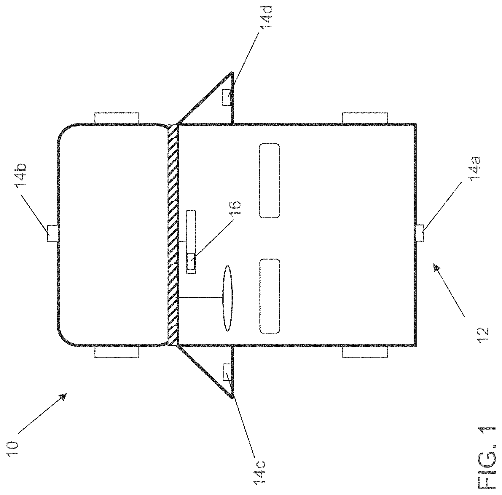
A vehicular vision system includes front, rear, driver-side camera and passenger-side cameras each having a respective field of view exterior of the vehicle. Each of the cameras connects with a central video/image processor via a respective mono coaxial cable. Image data captured by the imaging sensor of each camera is carried as captured to the central video/image processor via said the respective mono coaxial cable as a Low Voltage Differential Signal (LVDS). The central video/image processor generates an output provided to a video display device of the vehicle, with the video display device having a video display screen viewable by a driver of the vehicle. The video display screen is operable to display a birds-eye view of an area around the vehicle. The birds-eye view of the area around the vehicle is derived, at least in part, from image data captured by the imaging sensors of the cameras.
| Inventors: | Ihlenburg; Joern (Berlin, DE), Koppe; Andreas (Bad Homburg, DE), Gieseke; Achim (Gross-Umstadt, DE), Mahmoud; Hossam (Aschaffenburg, DE), Diessner; Horst D. (Rochester Hills, MI) | ||||||||||
|---|---|---|---|---|---|---|---|---|---|---|---|
| Applicant: |
|
||||||||||
| Assignee: | MAGNA ELECTRONICS INC. (Auburn
Hills, MI) |
||||||||||
| Family ID: | 48535967 | ||||||||||
| Appl. No.: | 16/125,903 | ||||||||||
| Filed: | September 10, 2018 |
Prior Publication Data
| Document Identifier | Publication Date | |
|---|---|---|
| US 20190001889 A1 | Jan 3, 2019 | |
Related U.S. Patent Documents
| Application Number | Filing Date | Patent Number | Issue Date | ||
|---|---|---|---|---|---|
| 14359341 | May 20, 2014 | 10071687 | |||
| PCT/US2012/066570 | |||||
| PCT/US2012/066571 | Nov 27, 2012 | ||||
| 61650667 | May 23, 2012 | ||||
| 61605409 | Mar 1, 2012 | ||||
| 61579682 | Dec 23, 2011 | ||||
| 61565713 | Dec 1, 2011 | ||||
| 61563965 | Nov 28, 2011 | ||||
| 61605409 | Mar 1, 2012 | ||||
| 61563965 | Nov 28, 2011 | ||||
| Current U.S. Class: | 1/1 |
| Current CPC Class: | G06T 7/246 (20170101); H04N 5/247 (20130101); G06K 9/00805 (20130101); B60R 1/00 (20130101); G02B 3/14 (20130101); H04N 7/18 (20130101); B60R 2300/8066 (20130101); B60R 2300/802 (20130101); B60R 2300/105 (20130101); G06T 2207/30252 (20130101); B60R 2300/806 (20130101); B60R 2300/303 (20130101); B60R 2300/8093 (20130101); G06T 2207/10016 (20130101) |
| Current International Class: | H04N 5/247 (20060101); G06T 7/246 (20170101); G02B 3/14 (20060101); G06K 9/00 (20060101); B60R 1/00 (20060101); H04N 7/18 (20060101) |
| Field of Search: | ;348/118 |
References Cited [Referenced By]
U.S. Patent Documents
| 4443769 | April 1984 | Aschwanden et al. |
| 4485398 | November 1984 | Chapin, Jr. et al. |
| 4720790 | January 1988 | Miki et al. |
| 4967319 | October 1990 | Seko |
| 4970653 | November 1990 | Kenue |
| 4987357 | January 1991 | Masaki |
| 4991054 | February 1991 | Walters |
| 5001558 | March 1991 | Burley et al. |
| 5003288 | March 1991 | Wilhelm |
| 5012082 | April 1991 | Watanabe |
| 5016977 | May 1991 | Baude et al. |
| 5027001 | June 1991 | Torbert |
| 5027200 | June 1991 | Petrossian et al. |
| 5044706 | September 1991 | Chen |
| 5055668 | October 1991 | French |
| 5059877 | October 1991 | Teder |
| 5064274 | November 1991 | Alten |
| 5072154 | December 1991 | Chen |
| 5086253 | February 1992 | Lawler |
| 5096287 | March 1992 | Kakinami et al. |
| 5097362 | March 1992 | Lynas |
| 5121200 | June 1992 | Choi |
| 5124549 | June 1992 | Michaels et al. |
| 5130709 | July 1992 | Toyama et al. |
| 5168378 | December 1992 | Black |
| 5170374 | December 1992 | Shimohigashi et al. |
| 5172235 | December 1992 | Wilm et al. |
| 5177606 | January 1993 | Koshizawa |
| 5177685 | January 1993 | Davis et al. |
| 5182502 | January 1993 | Slotkowski et al. |
| 5184956 | February 1993 | Langlais et al. |
| 5189561 | February 1993 | Hong |
| 5193000 | March 1993 | Lipton et al. |
| 5193029 | March 1993 | Schofield et al. |
| 5204778 | April 1993 | Bechtel |
| 5208701 | May 1993 | Maeda |
| 5208750 | May 1993 | Kurami et al. |
| 5214408 | May 1993 | Asayama |
| 5243524 | September 1993 | Ishida et al. |
| 5245422 | September 1993 | Borcherts et al. |
| 5255442 | October 1993 | Schierbeek et al. |
| 5276389 | January 1994 | Levers |
| 5285060 | February 1994 | Larson et al. |
| 5289182 | February 1994 | Brillard et al. |
| 5289321 | February 1994 | Secor |
| 5305012 | April 1994 | Faris |
| 5307136 | April 1994 | Saneyoshi |
| 5309137 | May 1994 | Kajiwara |
| 5313072 | May 1994 | Vachss |
| 5325096 | June 1994 | Pakett |
| 5325386 | June 1994 | Jewell et al. |
| 5329206 | July 1994 | Slotkowski et al. |
| 5331312 | July 1994 | Kudoh |
| 5336980 | August 1994 | Levers |
| 5341437 | August 1994 | Nakayama |
| 5351044 | September 1994 | Mathur et al. |
| 5355118 | October 1994 | Fukuhara |
| 5374852 | December 1994 | Parkes |
| 5386285 | January 1995 | Asayama |
| 5394333 | February 1995 | Kao |
| 5406395 | April 1995 | Wilson et al. |
| 5408346 | April 1995 | Trissel et al. |
| 5410346 | April 1995 | Saneyoshi et al. |
| 5414257 | May 1995 | Stanton |
| 5414461 | May 1995 | Kishi |
| 5416313 | May 1995 | Larson et al. |
| 5416318 | May 1995 | Hegyi |
| 5416478 | May 1995 | Morinaga |
| 5424952 | June 1995 | Asayama |
| 5426294 | June 1995 | Kobayashi et al. |
| 5430431 | July 1995 | Nelson |
| 5434407 | July 1995 | Bauer et al. |
| 5440428 | August 1995 | Klegg et al. |
| 5444478 | August 1995 | Lelong et al. |
| 5451822 | September 1995 | Bechtel et al. |
| 5457493 | October 1995 | Leddy et al. |
| 5461357 | October 1995 | Yoshioka et al. |
| 5461361 | October 1995 | Moore |
| 5469298 | November 1995 | Suman et al. |
| 5471515 | November 1995 | Fossum et al. |
| 5475494 | December 1995 | Nishida et al. |
| 5497306 | March 1996 | Pastrick |
| 5498866 | March 1996 | Bendicks et al. |
| 5500766 | March 1996 | Stonecypher |
| 5510983 | April 1996 | Lino |
| 5515448 | May 1996 | Nishitani |
| 5521633 | May 1996 | Nakajima et al. |
| 5528698 | June 1996 | Kamei |
| 5529138 | June 1996 | Shaw et al. |
| 5530240 | June 1996 | Larson et al. |
| 5530420 | June 1996 | Tsuchiya et al. |
| 5535144 | July 1996 | Kise |
| 5535314 | July 1996 | Alves et al. |
| 5537003 | July 1996 | Bechtel et al. |
| 5539397 | July 1996 | Asanuma et al. |
| 5541590 | July 1996 | Nishio |
| 5550677 | August 1996 | Schofield et al. |
| 5555555 | September 1996 | Sato et al. |
| 5568027 | October 1996 | Teder |
| 5574443 | November 1996 | Hsieh |
| 5581464 | December 1996 | Woll et al. |
| 5594222 | January 1997 | Caldwell |
| 5610756 | March 1997 | Lynam et al. |
| 5614788 | March 1997 | Mullins |
| 5619370 | April 1997 | Guinosso |
| 5632092 | May 1997 | Blank et al. |
| 5634709 | June 1997 | Iwama |
| 5642299 | June 1997 | Hardin et al. |
| 5648835 | July 1997 | Uzawa |
| 5650944 | July 1997 | Kise |
| 5660454 | August 1997 | Mod et al. |
| 5661303 | August 1997 | Teder |
| 5666028 | September 1997 | Bechtel et al. |
| 5670935 | September 1997 | Schofield et al. |
| 5677851 | October 1997 | Kingdon et al. |
| 5699044 | December 1997 | Van Lente et al. |
| 5724316 | March 1998 | Brunts |
| 5732379 | March 1998 | Eckert et al. |
| 5737226 | April 1998 | Olson et al. |
| 5757949 | May 1998 | Kinoshita et al. |
| 5760826 | June 1998 | Nayar |
| 5760828 | June 1998 | Cortes |
| 5760931 | June 1998 | Saburi et al. |
| 5760962 | June 1998 | Schofield et al. |
| 5761094 | June 1998 | Olson et al. |
| 5765116 | June 1998 | Wilson-Jones et al. |
| 5765118 | June 1998 | Fukatani |
| 5781437 | July 1998 | Wiemer et al. |
| 5786772 | July 1998 | Schofield et al. |
| 5790403 | August 1998 | Nakayama |
| 5790973 | August 1998 | Blaker |
| 5793308 | August 1998 | Rosinski et al. |
| 5793420 | August 1998 | Schmidt |
| 5796094 | August 1998 | Schofield et al. |
| 5835255 | November 1998 | Miles |
| 5837994 | November 1998 | Stam et al. |
| 5844505 | December 1998 | Van Ryzin |
| 5844682 | December 1998 | Kiyomoto et al. |
| 5845000 | December 1998 | Breed et al. |
| 5848802 | December 1998 | Breed et al. |
| 5850176 | December 1998 | Kinoshita et al. |
| 5850254 | December 1998 | Takano et al. |
| 5867591 | February 1999 | Onda |
| 5877707 | March 1999 | Kowalick |
| 5877897 | March 1999 | Schofield et al. |
| 5878357 | March 1999 | Sivashankar et al. |
| 5878370 | March 1999 | Olson |
| 5883739 | March 1999 | Ashihara et al. |
| 5884212 | March 1999 | Lion |
| 5890021 | March 1999 | Onoda |
| 5896085 | April 1999 | Mori et al. |
| 5899956 | May 1999 | Chan |
| 5915800 | June 1999 | Hiwatashi et al. |
| 5920367 | July 1999 | Kajimoto et al. |
| 5923027 | July 1999 | Stam et al. |
| 5924212 | July 1999 | Domanski |
| 5929786 | July 1999 | Schofield et al. |
| 5956181 | September 1999 | Lin |
| 5959555 | September 1999 | Furuta |
| 5963247 | October 1999 | Banitt |
| 5986796 | November 1999 | Miles |
| 5990469 | November 1999 | Bechtel et al. |
| 5990649 | November 1999 | Nagao et al. |
| 6020704 | February 2000 | Buschur |
| 6049171 | April 2000 | Stam et al. |
| 6052124 | April 2000 | Stein et al. |
| 6066933 | May 2000 | Ponziana |
| 6084519 | July 2000 | Coulling et al. |
| 6091833 | July 2000 | Yasui et al. |
| 6097024 | August 2000 | Stam et al. |
| 6100799 | August 2000 | Fenk |
| 6100811 | August 2000 | Hsu et al. |
| 6115159 | September 2000 | Baker |
| 6144022 | November 2000 | Tenenbaum et al. |
| 6175300 | January 2001 | Kendrick |
| 6178034 | January 2001 | Allemand et al. |
| 6198409 | March 2001 | Schofield et al. |
| 6201642 | March 2001 | Bos |
| 6223114 | April 2001 | Boros et al. |
| 6226061 | May 2001 | Tagusa |
| 6227689 | May 2001 | Miller |
| 6250148 | June 2001 | Lynam |
| 6259423 | July 2001 | Tokito et al. |
| 6266082 | July 2001 | Yonezawa et al. |
| 6266442 | July 2001 | Laumeyer et al. |
| 6285393 | September 2001 | Shimoura et al. |
| 6285778 | September 2001 | Nakajima et al. |
| 6294989 | September 2001 | Schofield et al. |
| 6297781 | October 2001 | Turnbull et al. |
| 6302545 | October 2001 | Schofield et al. |
| 6310611 | October 2001 | Caldwell |
| 6313454 | November 2001 | Bos et al. |
| 6317057 | November 2001 | Lee |
| 6320282 | November 2001 | Caldwell |
| 6333759 | December 2001 | Mazzilli |
| 6341523 | January 2002 | Lynam |
| 6353392 | March 2002 | Schofield et al. |
| 6370329 | April 2002 | Teuchert |
| 6392315 | May 2002 | Jones et al. |
| 6396397 | May 2002 | Bos et al. |
| 6411204 | June 2002 | Bloomfield et al. |
| 6420975 | July 2002 | DeLine et al. |
| 6424273 | July 2002 | Gutta et al. |
| 6430303 | August 2002 | Naoi et al. |
| 6442465 | August 2002 | Breed et al. |
| 6477326 | November 2002 | Partynski |
| 6477464 | November 2002 | McCarthy et al. |
| 6497503 | December 2002 | Dassanayake et al. |
| 6498620 | December 2002 | Schofield et al. |
| 6516664 | February 2003 | Lynam |
| 6523964 | February 2003 | Schofield et al. |
| 6534884 | March 2003 | Marcus et al. |
| 6539306 | March 2003 | Turnbull |
| 6547133 | April 2003 | Devries, Jr. et al. |
| 6553130 | April 2003 | Lemelson et al. |
| 6559435 | May 2003 | Schofield et al. |
| 6570998 | May 2003 | Ohtsuka et al. |
| 6574033 | June 2003 | Chui et al. |
| 6578017 | June 2003 | Ebersole et al. |
| 6587573 | July 2003 | Stam et al. |
| 6589625 | July 2003 | Kothari et al. |
| 6593011 | July 2003 | Liu et al. |
| 6593698 | July 2003 | Stam et al. |
| 6594583 | July 2003 | Ogura et al. |
| 6605775 | August 2003 | Seeber et al. |
| 6611202 | August 2003 | Schofield et al. |
| 6611610 | August 2003 | Stam et al. |
| 6627918 | September 2003 | Getz et al. |
| 6631316 | October 2003 | Stam et al. |
| 6631994 | October 2003 | Suzuki et al. |
| 6636258 | October 2003 | Strumolo |
| 6648477 | November 2003 | Hutzel et al. |
| 6650455 | November 2003 | Miles |
| 6672731 | January 2004 | Schnell et al. |
| 6674562 | January 2004 | Miles |
| 6678056 | January 2004 | Downs |
| 6678614 | January 2004 | McCarthy et al. |
| 6680792 | January 2004 | Miles |
| 6690268 | February 2004 | Schofield et al. |
| 6700605 | March 2004 | Toyoda et al. |
| 6703925 | March 2004 | Steffel |
| 6704621 | March 2004 | Stein et al. |
| 6710908 | March 2004 | Miles et al. |
| 6711474 | March 2004 | Treyz et al. |
| 6714331 | March 2004 | Lewis et al. |
| 6717610 | April 2004 | Bos et al. |
| 6735506 | May 2004 | Breed et al. |
| 6741377 | May 2004 | Miles |
| 6744353 | June 2004 | Sjonell |
| 6757109 | June 2004 | Bos |
| 6762867 | July 2004 | Lippert et al. |
| 6794119 | September 2004 | Miles |
| 6795221 | September 2004 | Urey |
| 6802617 | October 2004 | Schofield et al. |
| 6806452 | October 2004 | Bos et al. |
| 6807287 | October 2004 | Hermans |
| 6819231 | November 2004 | Berberich et al. |
| 6822563 | November 2004 | Bos et al. |
| 6823241 | November 2004 | Shirato et al. |
| 6824281 | November 2004 | Schofield et al. |
| 6850156 | February 2005 | Bloomfield et al. |
| 6864930 | March 2005 | Matsushita et al. |
| 6882287 | April 2005 | Schofield |
| 6889161 | May 2005 | Winner et al. |
| 6909753 | June 2005 | Meehan et al. |
| 6946978 | September 2005 | Schofield |
| 6953253 | October 2005 | Schofield et al. |
| 6968736 | November 2005 | Lynam |
| 6975775 | December 2005 | Rykowski et al. |
| 6989736 | January 2006 | Berberich et al. |
| 7004606 | February 2006 | Schofield |
| 7005974 | February 2006 | McMahon et al. |
| 7038577 | May 2006 | Pawlicki et al. |
| 7062300 | June 2006 | Kim |
| 7065432 | June 2006 | Moisel et al. |
| 7079017 | July 2006 | Lang et al. |
| 7085637 | August 2006 | Breed et al. |
| 7092548 | August 2006 | Laumeyer et al. |
| 7111968 | September 2006 | Bauer et al. |
| 7113867 | September 2006 | Stein |
| 7116246 | October 2006 | Winter et al. |
| 7123168 | October 2006 | Schofield |
| 7133661 | November 2006 | Hatae et al. |
| 7136753 | November 2006 | Samukawa et al. |
| 7145519 | December 2006 | Takahashi et al. |
| 7149613 | December 2006 | Stam et al. |
| 7151996 | December 2006 | Stein |
| 7161616 | January 2007 | Okamoto et al. |
| 7167796 | January 2007 | Taylor et al. |
| 7195381 | March 2007 | Lynam et al. |
| 7202776 | April 2007 | Breed |
| 7227611 | June 2007 | Hull et al. |
| 7230640 | June 2007 | Regensburger et al. |
| 7248283 | July 2007 | Takagi et al. |
| 7295229 | November 2007 | Kumata et al. |
| 7311406 | December 2007 | Schofield et al. |
| 7325934 | February 2008 | Schofield et al. |
| 7325935 | February 2008 | Schofield et al. |
| 7336299 | February 2008 | Kostrzewski et al. |
| 7338177 | March 2008 | Lynam |
| 7365769 | April 2008 | Mager |
| 7370983 | May 2008 | DeWind et al. |
| 7375803 | May 2008 | Bamji |
| 7380948 | June 2008 | Schofield et al. |
| 7381089 | June 2008 | Hosier, Sr. |
| 7388182 | June 2008 | Schofield et al. |
| 7402786 | July 2008 | Schofield et al. |
| 7423821 | September 2008 | Bechtel et al. |
| 7460951 | December 2008 | Altan |
| 7480149 | January 2009 | DeWard et al. |
| 7482916 | January 2009 | Au et al. |
| 7490007 | February 2009 | Taylor et al. |
| 7492281 | February 2009 | Lynam et al. |
| 7526103 | April 2009 | Schofield et al. |
| 7532109 | May 2009 | Takahama et al. |
| 7541743 | June 2009 | Salmeen et al. |
| 7561181 | July 2009 | Schofield et al. |
| 7565006 | July 2009 | Stam et al. |
| 7566851 | July 2009 | Stein et al. |
| 7567291 | July 2009 | Bechtel et al. |
| 7576767 | August 2009 | Lee et al. |
| 7581859 | September 2009 | Lynam |
| 7592928 | September 2009 | Chinomi et al. |
| 7605856 | October 2009 | Imoto |
| 7616781 | November 2009 | Schofield et al. |
| 7619508 | November 2009 | Lynam et al. |
| 7633383 | December 2009 | Dunsmoir et al. |
| 7639149 | December 2009 | Katoh |
| 7681960 | March 2010 | Wanke et al. |
| 7711201 | May 2010 | Wong et al. |
| 7720580 | May 2010 | Higgins-Luthman |
| 7724962 | May 2010 | Zhu et al. |
| 7777611 | August 2010 | Desai |
| 7786898 | August 2010 | Stein et al. |
| 7792329 | September 2010 | Schofield et al. |
| 7843451 | November 2010 | Lafon |
| 7855755 | December 2010 | Weller et al. |
| 7855778 | December 2010 | Yung et al. |
| 7881496 | February 2011 | Camilleri et al. |
| 7914187 | March 2011 | Higgins-Luthman et al. |
| 7925441 | April 2011 | Maemura |
| 7930160 | April 2011 | Hosagrahara et al. |
| 7949486 | May 2011 | Denny et al. |
| 7952490 | May 2011 | Fechner et al. |
| 7965336 | June 2011 | Bingle et al. |
| 8009868 | August 2011 | Abe |
| 8013780 | September 2011 | Lynam |
| 8017898 | September 2011 | Lu et al. |
| 8027029 | September 2011 | Lu et al. |
| 8058977 | November 2011 | Lynam |
| 8064643 | November 2011 | Stein et al. |
| 8072486 | December 2011 | Namba et al. |
| 8082101 | December 2011 | Stein et al. |
| 8090976 | January 2012 | Maciver et al. |
| 8134596 | March 2012 | Lei et al. |
| 8164628 | April 2012 | Stein et al. |
| 8203440 | June 2012 | Schofield et al. |
| 8224031 | July 2012 | Saito |
| 8233045 | July 2012 | Luo et al. |
| 8254635 | August 2012 | Stein et al. |
| 8294563 | October 2012 | Shimoda et al. |
| 8300886 | October 2012 | Hoffmann |
| 8320628 | November 2012 | Cheng et al. |
| 8340866 | December 2012 | Hanzawa et al. |
| 8378851 | February 2013 | Stein et al. |
| 8421865 | April 2013 | Euler et al. |
| 8452055 | May 2013 | Stein et al. |
| 8502860 | August 2013 | Demirdjian |
| 8553088 | October 2013 | Stein et al. |
| 8849495 | September 2014 | Chundrik, Jr. et al. |
| 8908039 | December 2014 | De Wind et al. |
| 9019090 | April 2015 | Weller et al. |
| 9041806 | May 2015 | Baur et al. |
| 9090234 | July 2015 | Johnson et al. |
| 9092986 | July 2015 | Salomonsson et al. |
| 9146898 | September 2015 | Ihlenburg et al. |
| 9205776 | December 2015 | Turk |
| 9210307 | December 2015 | Gebauer et al. |
| 9900490 | February 2018 | Ihlenburg et al. |
| 10071687 | September 2018 | Ihlenburg et al. |
| 2002/0005778 | January 2002 | Breed et al. |
| 2002/0011611 | January 2002 | Huang et al. |
| 2002/0015153 | February 2002 | Downs |
| 2002/0037054 | March 2002 | Schurig |
| 2002/0044065 | April 2002 | Quist et al. |
| 2002/0113873 | August 2002 | Williams |
| 2002/0116106 | August 2002 | Breed et al. |
| 2002/0149679 | October 2002 | Deangelis et al. |
| 2003/0103142 | June 2003 | Hitomi et al. |
| 2003/0137586 | July 2003 | Lewellen |
| 2003/0222982 | December 2003 | Hamdan et al. |
| 2004/0032321 | February 2004 | McMahon et al. |
| 2004/0114381 | June 2004 | Salmeen et al. |
| 2004/0164228 | August 2004 | Fogg et al. |
| 2005/0078389 | April 2005 | Kulas et al. |
| 2005/0134983 | June 2005 | Lynam |
| 2005/0219852 | October 2005 | Stam et al. |
| 2005/0237385 | October 2005 | Kosaka et al. |
| 2005/0264891 | December 2005 | Uken et al. |
| 2006/0018511 | January 2006 | Stam et al. |
| 2006/0018512 | January 2006 | Stam et al. |
| 2006/0061008 | March 2006 | Kamer et al. |
| 2006/0072011 | April 2006 | Okada |
| 2006/0091813 | May 2006 | Stam et al. |
| 2006/0103727 | May 2006 | Tseng |
| 2006/0133476 | June 2006 | Page |
| 2006/0164221 | July 2006 | Jensen |
| 2006/0212624 | September 2006 | Kim |
| 2006/0232670 | October 2006 | Chu |
| 2006/0250501 | November 2006 | Widmann et al. |
| 2006/0254805 | November 2006 | Scherer et al. |
| 2006/0255920 | November 2006 | Maeda et al. |
| 2006/0290479 | December 2006 | Akatsuka et al. |
| 2007/0024724 | February 2007 | Stein et al. |
| 2007/0103313 | May 2007 | Washington |
| 2007/0104476 | May 2007 | Yasutomi et al. |
| 2007/0242339 | October 2007 | Bradley |
| 2007/0257923 | November 2007 | Whitby-Strevens |
| 2008/0043099 | February 2008 | Stein |
| 2008/0063129 | March 2008 | Voutilainen |
| 2008/0147321 | June 2008 | Howard et al. |
| 2008/0150814 | June 2008 | Hedou |
| 2008/0166024 | July 2008 | Iketani |
| 2008/0192132 | August 2008 | Bechtel et al. |
| 2008/0266396 | October 2008 | Stein |
| 2009/0024756 | January 2009 | Spalla et al. |
| 2009/0093938 | April 2009 | Isaji et al. |
| 2009/0113509 | April 2009 | Tseng et al. |
| 2009/0160987 | June 2009 | Bechtel et al. |
| 2009/0171559 | July 2009 | Lehtiniemi et al. |
| 2009/0177347 | July 2009 | Breuer et al. |
| 2009/0190015 | July 2009 | Bechtel et al. |
| 2009/0243824 | October 2009 | Peterson et al. |
| 2009/0244361 | October 2009 | Gebauer et al. |
| 2009/0256938 | October 2009 | Bechtel et al. |
| 2009/0265069 | October 2009 | Desbrunes |
| 2009/0273524 | November 2009 | Furuya |
| 2009/0290032 | November 2009 | Zhang et al. |
| 2009/0295181 | December 2009 | Lawlor et al. |
| 2010/0020170 | January 2010 | Higgins-Luthman et al. |
| 2010/0076621 | March 2010 | Kubotani et al. |
| 2010/0088021 | April 2010 | Viner |
| 2010/0097469 | April 2010 | Blank et al. |
| 2010/0097519 | April 2010 | Byrne et al. |
| 2010/0110939 | May 2010 | Fukuda |
| 2010/0118145 | May 2010 | Betham et al. |
| 2010/0228437 | September 2010 | Hanzawa et al. |
| 2010/0231409 | September 2010 | Okada et al. |
| 2010/0296519 | November 2010 | Jones |
| 2011/0115615 | May 2011 | Luo et al. |
| 2011/0141381 | June 2011 | Minikey, Jr. et al. |
| 2011/0157309 | June 2011 | Bennett et al. |
| 2011/0193961 | August 2011 | Peterson |
| 2011/0216201 | September 2011 | McAndrew et al. |
| 2011/0224978 | September 2011 | Sawada |
| 2011/0228088 | September 2011 | Gloger |
| 2011/0257973 | October 2011 | Chutorash et al. |
| 2011/0286544 | November 2011 | Avudainayagam et al. |
| 2012/0044066 | February 2012 | Mauderer et al. |
| 2012/0045112 | February 2012 | Lundblad et al. |
| 2012/0050550 | March 2012 | Oba et al. |
| 2012/0062743 | March 2012 | Lynam et al. |
| 2012/0069184 | March 2012 | Hoffmann |
| 2012/0069185 | March 2012 | Stein |
| 2012/0127062 | May 2012 | Bar-Zeev |
| 2012/0154591 | June 2012 | Baur et al. |
| 2012/0186447 | July 2012 | Hodgson et al. |
| 2012/0200707 | August 2012 | Stein et al. |
| 2012/0218412 | August 2012 | Dellantoni et al. |
| 2012/0239242 | September 2012 | Uehara |
| 2012/0245817 | September 2012 | Cooprider et al. |
| 2012/0262340 | October 2012 | Hassan et al. |
| 2012/0287140 | November 2012 | Lin et al. |
| 2012/0303222 | November 2012 | Cooprider et al. |
| 2012/0314071 | December 2012 | Rosenbaum et al. |
| 2012/0320209 | December 2012 | Vico et al. |
| 2013/0103259 | April 2013 | Eng |
| 2013/0116859 | May 2013 | Ihienburg et al. |
| 2013/0124052 | May 2013 | Hahne |
| 2013/0129150 | May 2013 | Saito |
| 2013/0131918 | May 2013 | Hahne |
| 2013/0134964 | May 2013 | Ahrentorp et al. |
| 2013/0141578 | June 2013 | Chundrlik, Jr. et al. |
| 2013/0141580 | June 2013 | Stein et al. |
| 2013/0147957 | June 2013 | Stein |
| 2013/0169812 | July 2013 | Lu et al. |
| 2013/0187445 | July 2013 | Mutzabaugh |
| 2013/0222593 | August 2013 | Byrne et al. |
| 2013/0242413 | September 2013 | Baba |
| 2013/0278769 | October 2013 | Nix et al. |
| 2013/0286193 | October 2013 | Pflug |
| 2013/0314503 | November 2013 | Nix et al. |
| 2013/0328672 | December 2013 | Sesti et al. |
| 2014/0009633 | January 2014 | Chopra et al. |
| 2014/0043473 | February 2014 | Gupta et al. |
| 2014/0063254 | March 2014 | Shi et al. |
| 2014/0067206 | March 2014 | Pflug |
| 2014/0098229 | April 2014 | Lu et al. |
| 2014/0152778 | June 2014 | Ihlenburg et al. |
| 2014/0156157 | June 2014 | Johnson et al. |
| 2014/0160291 | June 2014 | Schaffner |
| 2014/0176711 | June 2014 | Kirchner et al. |
| 2014/0218529 | August 2014 | Mahmoud et al. |
| 2014/0218531 | August 2014 | Michiguchi |
| 2014/0218535 | August 2014 | Ihlenburg et al. |
| 2014/0222280 | August 2014 | Salomonsson et al. |
| 2014/0247352 | September 2014 | Rathi et al. |
| 2014/0247354 | September 2014 | Knudsen |
| 2014/0247355 | September 2014 | Ihlenburg |
| 2014/0313339 | October 2014 | Diessner |
| 2014/0320658 | October 2014 | Pliefke |
| 2014/0333729 | November 2014 | Pflug |
| 2014/0340510 | November 2014 | Ihlenburg et al. |
| 2014/0347486 | November 2014 | Okouneva |
| 2014/0362209 | December 2014 | Ziegenspeck et al. |
| 2014/0373345 | December 2014 | Steigerwald |
| 2014/0379233 | December 2014 | Chundrlik, Jr. et al. |
| 2015/0042807 | February 2015 | Ihlenburg et al. |
| 2015/0156383 | June 2015 | Biemer et al. |
| 2015/0222795 | August 2015 | Sauer et al. |
| 2015/0232030 | August 2015 | Bongwald |
| 2015/0294169 | October 2015 | Zhou et al. |
| 2015/0296135 | October 2015 | Wacquant et al. |
| 1115250 | Jul 2001 | EP | |||
| 2377094 | Oct 2011 | EP | |||
| 2667325 | Nov 2013 | EP | |||
| H1168538 | Jul 1989 | JP | |||
| 200274339 | Mar 2002 | JP | |||
| 2012139636 | Oct 2012 | WO | |||
| 2012139660 | Oct 2012 | WO | |||
| 2012143036 | Oct 2012 | WO | |||
Other References
|
Achler et al., "Vehicle Wheel Detector using 2D Filter Banks," IEEE Intelligent Vehicles Symposium of Jun. 2004. cited by applicant . Behringer et al., "Simultaneous Estimation of Pitch Angle and Lane Width from the Video Image of a Marked Road," pp. 966-973, Sep. 12-16, 1994. cited by applicant . Broggi et al., "Multi-Resolution Vehicle Detection using Artificial Vision," IEEE Intelligent Vehicles Symposium of Jun. 2004. cited by applicant . Kastrinaki et al., "A survey of video processing techniques for traffic applications". cited by applicant . Philomin et al., "Pedestrain Tracking from a Moving Vehicle". cited by applicant . Sahli et al., "A Kalman Filter-Based Update Scheme for Road Following," IAPR Workshop on Machine Vision Applications, pp. 5-9, Nov. 12-14, 1996. cited by applicant . Sun et al., "On-road vehicle detection using optical sensors: a review", IEEE Conference on Intelligent Transportation Systems, 2004. cited by applicant . Van Leeuwen et al., "Motion Estimation with a Mobile Camera for Traffic Applications", IEEE, US, vol. 1, Oct. 3, 2000, pp. 58-63. cited by applicant . Van Leeuwen et al., "Motion Interpretation for In-Car Vision Systems", IEEE, US, vol. 1, Sep. 30, 2002, p. 135-140. cited by applicant . Van Leeuwen et al., "Real-Time Vehicle Tracking in Image Sequences", IEEE, US, vol. 3, May 21, 2001, pp. 2049-2054, XP010547308. cited by applicant . Van Leeuwen et al., "Requirements for Motion Estimation in Image Sequences for Traffic Applications", IEEE, US, vol. 1, May 24, 1999, pp. 145-150, XP010340272. cited by applicant . International Search Report and Written Opinion dated Feb. 8, 213 for PCT Application No. PCT/US2012/066571. cited by applicant. |
Primary Examiner: Jiang; Zaihan
Attorney, Agent or Firm: Honigman LLP
Parent Case Text
CROSS REFERENCE TO RELATED APPLICATIONS
The present application is a continuation of U.S. patent application Ser. No. 14/359,341, filed May 20, 2014, now U.S. Pat. No. 10,071,687, which is a 371 national phase filing of PCT Application No. PCT/US2012/066571, filed Nov. 27, 2012, which claims the filing benefit of U.S. provisional applications, Ser. No. 61/650,667, filed May 23, 2012; Ser. No. 61/605,409, filed Mar. 1, 2012; Ser. No. 61/579,682, filed Dec. 23, 2011; Ser. No. 61/565,713, filed Dec. 1, 2011; and Ser. No. 61/563,965, filed Nov. 28, 2011, which are hereby incorporated herein by reference in their entireties, and U.S. patent application Ser. No. 14/359,341 is a continuation-in-part of PCT/US2012/066570, filed Nov. 27, 2012, which claims the filing benefit of U.S. provisional applications, Ser. No. 61/605,409, filed Mar. 1, 2012, and Ser. No. 61/563,965, filed Nov. 28, 2011.
Claims
The invention claimed is:
1. A vehicular vision system, said vehicular vision system comprising: a plurality of cameras disposed at a vehicle equipped with said vehicular vision system, each having a respective field of view exterior of the vehicle; said plurality of cameras comprising a front camera disposed at a front portion of the equipped vehicle, said front camera comprising an imaging sensor comprising an array of a plurality of photosensor elements arranged in multiple columns and multiple rows, the imaging sensor of said front camera having a forward field of view exterior of the equipped vehicle and operable to capture image data; said plurality of cameras comprising a rear camera disposed at a rear portion of the equipped vehicle, said rear camera comprising an imaging sensor comprising an array of a plurality of photosensor elements arranged in multiple columns and multiple rows, the imaging sensor of said rear camera having a rearward field of view exterior of the equipped vehicle and operable to capture image data; said plurality of cameras comprising a driver-side camera disposed at a driver-side portion of the equipped vehicle, said driver-side camera comprising an imaging sensor comprising an array of a plurality of photosensor elements arranged in multiple columns and multiple rows, the imaging sensor of said driver-side camera having a sideward field of view exterior of the equipped vehicle and operable to capture image data; said plurality of cameras comprising a passenger-side camera disposed at a passenger-side portion of the equipped vehicle, said passenger-side camera comprising an imaging sensor comprising an array of a plurality of photosensor elements arranged in multiple columns and multiple rows, the imaging sensor of said passenger-side camera having a sideward field of view exterior of the equipped vehicle and operable to capture image data; a central video/image processor; wherein said front camera connects with said central video/image processor via a first mono coaxial cable; wherein said rear camera connects with said central video/image processor via a second mono coaxial cable; wherein said driver-side camera connects with said central video/image processor via a third mono coaxial cable; wherein said passenger-side camera connects with said central video/image processor via a fourth mono coaxial cable; wherein image data captured by the imaging sensor of said front camera is carried as captured to said central video/image processor via said first mono coaxial cable as a Low Voltage Differential Signal (LVDS); wherein image data captured by the imaging sensor of said rear camera is carried as captured to said central video/image processor via said second mono coaxial cable as an LVDS; wherein image data captured by the imaging sensor of said driver-side camera is carried as captured to said central video/image processor via said third mono coaxial cable as an LVDS; wherein image data captured by the imaging sensor of said passenger-side camera is carried as captured to said central video/image processor via said fourth mono coaxial cable as an LVDS; wherein said first mono coaxial cable functions as a bidirectional channel carrying control data from said central video/image processor to said front camera and carrying image data captured by the imaging sensor of said front camera from said front camera to said central video/image processor; wherein said second mono coaxial cable functions as a bidirectional channel carrying control data from said central video/image processor to said rear camera and carrying image data captured by the imaging sensor of said rear camera from said rear camera to said central video/image processor; wherein said third mono coaxial cable functions as a bidirectional channel carrying control data from said central video/image processor to said driver-side camera and carrying image data captured by the imaging sensor of said driver-side camera from said driver-side camera to said central video/image processor; wherein said fourth mono coaxial cable functions as a bidirectional channel carrying control data from said central video/image processor to said passenger-side camera and carrying image data captured by the imaging sensor of said passenger-side camera from said passenger-side camera to said central video/image processor; wherein said central video/image processor generates an output provided to a video display device of the equipped vehicle, said video display device comprising a video display screen viewable by a driver of the equipped vehicle; wherein said video display screen is operable to display a birds-eye view of an area around the equipped vehicle; and wherein the birds-eye view of the area around the equipped vehicle is derived, at least in part, from image data captured by the imaging sensors of (i) said front camera, (ii) said rear camera, (iii) said driver-side camera and (iv) said passenger-side camera.
2. The vision system of claim 1, wherein image data captured by at least said rear camera of said plurality of cameras is processed at said central video/image processor to detect an object to the rear of the equipped vehicle.
3. The vision system of claim 2, wherein, responsive to said processing at said central video/image processor, said vision system determines movement vectors, and wherein, responsive to determination of movement vectors, said vision system determines an object of interest in the field of view of at least said rear camera.
4. The vision system of claim 1, wherein said central video/image processor is operable to process input from at least one of an ultrasound sensor, a radar sensor, an infrared sensor, a Lidar sensor and a Laser sensor.
5. The vision system of claim 1, wherein said central video/image processor receives input from at least one non-permanently mounted device.
6. The vision system of claim 5, wherein at least one of (i) said non-permanently mounted device is plugged into a port attached to a bus architecture of the vehicle, (ii) said non-permanently mounted device is wirelessly connected to a bus architecture of the vehicle, (iii) said non-permanently mounted device comprises a mobile phone device and (iv) said non-permanently mounted device comprises a camera.
7. The vision system of claim 5, wherein said non-permanently mounted device comprises a camera that is wirelessly linked to the equipped vehicle.
8. The vision system of claim 1, wherein, responsive at least in part to processing of image data at said central video/image processor detecting presence of a hazardous object exterior of the equipped vehicle, an alert is provided to the driver of the vehicle.
9. The vision system of claim 1, wherein each camera of said plurality of cameras comprises a wafer level camera.
10. The vision system of claim 1, wherein each camera of said plurality of cameras comprises an LVDS chip.
11. The vision system of claim 1, wherein said driver-side camera disposed at the driver-side portion of the equipped vehicle is part of a driver-side exterior mirror assembly of the equipped vehicle, and wherein said passenger-side camera disposed at the passenger-side portion of the equipped vehicle is part of a passenger-side exterior mirror assembly of the equipped vehicle.
12. The vision system of claim 1, wherein said central video/image processor is disposed at a head unit of the equipped vehicle.
13. The vision system of claim 1, wherein said central video/image processor comprises a graphic engine.
14. The vision system of claim 1, wherein said rear camera comprises a rear backup camera of the equipped vehicle.
15. A vehicular vision system, said vehicular vision system comprising: a plurality of cameras disposed at a vehicle equipped with said vehicular vision system, each having a respective field of view exterior of the vehicle; said plurality of cameras comprising a front camera disposed at a front portion of the equipped vehicle, said front camera comprising an imaging sensor comprising an array of a plurality of photosensor elements arranged in multiple columns and multiple rows, the imaging sensor of said front camera having a forward field of view exterior of the equipped vehicle and operable to capture image data; said plurality of cameras comprising a rear camera disposed at a rear portion of the equipped vehicle, said rear camera comprising an imaging sensor comprising an array of a plurality of photosensor elements arranged in multiple columns and multiple rows, the imaging sensor of said rear camera having a rearward field of view exterior of the equipped vehicle and operable to capture image data; said plurality of cameras comprising a driver-side camera disposed at a driver-side portion of the equipped vehicle, said driver-side camera comprising an imaging sensor comprising an array of a plurality of photosensor elements arranged in multiple columns and multiple rows, the imaging sensor of said driver-side camera having a sideward field of view exterior of the equipped vehicle and operable to capture image data; wherein said driver-side camera disposed at the driver-side portion of the equipped vehicle is part of a driver-side exterior mirror assembly of the equipped vehicle; said plurality of cameras comprising a passenger-side camera disposed at a passenger-side portion of the equipped vehicle, said passenger-side camera comprising an imaging sensor comprising an array of a plurality of photosensor elements arranged in multiple columns and multiple rows, the imaging sensor of said passenger-side camera having a sideward field of view exterior of the equipped vehicle and operable to capture image data; wherein said passenger-side camera disposed at the passenger-side portion of the equipped vehicle is part of a passenger-side exterior mirror assembly of the equipped vehicle; a central video/image processor; wherein said front camera connects with said central video/image processor via a first mono coaxial cable; wherein said rear camera connects with said central video/image processor via a second mono coaxial cable; wherein said driver-side camera connects with said central video/image processor via a third mono coaxial cable; wherein said passenger-side camera connects with said central video/image processor via a fourth mono coaxial cable; wherein image data captured by the imaging sensor of said front camera is carried as captured to said central video/image processor via said first mono coaxial cable as a Low Voltage Differential Signal (LVDS); wherein image data captured by the imaging sensor of said rear camera is carried as captured to said central video/image processor via said second mono coaxial cable as an LVDS; wherein image data captured by the imaging sensor of said driver-side camera is carried as captured to said central video/image processor via said third mono coaxial cable as an LVDS; wherein image data captured by the imaging sensor of said passenger-side camera is carried as captured to said central video/image processor via said fourth mono coaxial cable as an LVDS; wherein said first mono coaxial cable functions as a bidirectional channel carrying control data from said central video/image processor to said front camera and carrying image data captured by the imaging sensor of said front camera from said front camera to said central video/image processor; wherein said second mono coaxial cable functions as a bidirectional channel carrying control data from said central video/image processor to said rear camera and carrying image data captured by the imaging sensor of said rear camera from said rear camera to said central video/image processor; wherein said third mono coaxial cable functions as a bidirectional channel carrying control data from said central video/image processor to said driver-side camera and carrying image data captured by the imaging sensor of said driver-side camera from said driver-side camera to said central video/image processor; wherein said fourth mono coaxial cable functions as a bidirectional channel carrying control data from said central video/image processor to said passenger-side camera and carrying image data captured by the imaging sensor of said passenger-side camera from said passenger-side camera to said central video/image processor; wherein said central video/image processor generates an output provided to a video display device of the equipped vehicle, said video display device comprising a video display screen viewable by a driver of the equipped vehicle; wherein said video display screen is operable to display a birds-eye view of an area around the equipped vehicle; wherein the birds-eye view of the area around the equipped vehicle is derived, at least in part, from image data captured by the imaging sensors of (i) said front camera, (ii) said rear camera, (iii) said driver-side camera and (iv) said passenger-side camera; and wherein image data captured by at least said rear camera of said plurality of cameras is processed at said central video/image processor to detect an object to the rear of the equipped vehicle.
16. The vision system of claim 15, wherein, responsive to said processing at said central video/image processor, said vision system determines movement vectors, and wherein, responsive to determination of movement vectors, said vision system determines an object of interest in the field of view of at least said rear camera.
17. The vision system of claim 15, wherein said central video/image processor is operable to process input from at least one sensor selected from the group consisting of an ultrasound sensor, a radar sensor and a Lidar sensor.
18. The vision system of claim 15, wherein each camera of said plurality of cameras comprises an LVDS chip.
19. The vision system of claim 18, wherein said central video/image processor comprises a graphic engine.
20. A vehicular vision system, said vehicular vision system comprising: a plurality of cameras disposed at a vehicle equipped with said vehicular vision system, each having a respective field of view exterior of the vehicle; said plurality of cameras comprising a front camera disposed at a front portion of the equipped vehicle, said front camera comprising an imaging sensor comprising an array of a plurality of photosensor elements arranged in multiple columns and multiple rows, the imaging sensor of said front camera having a forward field of view exterior of the equipped vehicle and operable to capture image data; said plurality of cameras comprising a rear camera disposed at a rear portion of the equipped vehicle, said rear camera comprising an imaging sensor comprising an array of a plurality of photosensor elements arranged in multiple columns and multiple rows, the imaging sensor of said rear camera having a rearward field of view exterior of the equipped vehicle and operable to capture image data; wherein said rear camera comprises a rear backup camera of the equipped vehicle; said plurality of cameras comprising a driver-side camera disposed at a driver-side portion of the equipped vehicle, said driver-side camera comprising an imaging sensor comprising an array of a plurality of photosensor elements arranged in multiple columns and multiple rows, the imaging sensor of said driver-side camera having a sideward field of view exterior of the equipped vehicle and operable to capture image data; wherein said driver-side camera disposed at the driver-side portion of the equipped vehicle is part of a driver-side exterior mirror assembly of the equipped vehicle; said plurality of cameras comprising a passenger-side camera disposed at a passenger-side portion of the equipped vehicle, said passenger-side camera comprising an imaging sensor comprising an array of a plurality of photosensor elements arranged in multiple columns and multiple rows, the imaging sensor of said passenger-side camera having a sideward field of view exterior of the equipped vehicle and operable to capture image data; wherein said passenger-side camera disposed at the passenger-side portion of the equipped vehicle is part of a passenger-side exterior mirror assembly of the equipped vehicle; a central video/image processor; wherein said front camera connects with said central video/image processor via a first mono coaxial cable; wherein said rear camera connects with said central video/image processor via a second mono coaxial cable; wherein said driver-side camera connects with said central video/image processor via a third mono coaxial cable; wherein said passenger-side camera connects with said central video/image processor via a fourth mono coaxial cable; wherein image data captured by the imaging sensor of said front camera is carried as captured to said central video/image processor via said first mono coaxial cable as a Low Voltage Differential Signal (LVDS); wherein image data captured by the imaging sensor of said rear camera is carried as captured to said central video/image processor via said second mono coaxial cable as an LVDS; wherein image data captured by the imaging sensor of said driver-side camera is carried as captured to said central video/image processor via said third mono coaxial cable as an LVDS; wherein image data captured by the imaging sensor of said passenger-side camera is carried as captured to said central video/image processor via said fourth mono coaxial cable as an LVDS; wherein said first mono coaxial cable functions as a bidirectional channel carrying control data from said central video/image processor to said front camera and carrying image data captured by the imaging sensor of said front camera from said front camera to said central video/image processor; wherein said second mono coaxial cable functions as a bidirectional channel carrying control data from said central video/image processor to said rear camera and carrying image data captured by the imaging sensor of said rear camera from said rear camera to said central video/image processor; wherein said third mono coaxial cable functions as a bidirectional channel carrying control data from said central video/image processor to said driver-side camera and carrying image data captured by the imaging sensor of said driver-side camera from said driver-side camera to said central video/image processor; wherein said fourth mono coaxial cable functions as a bidirectional channel carrying control data from said central video/image processor to said passenger-side camera and carrying image data captured by the imaging sensor of said passenger-side camera from said passenger-side camera to said central video/image processor; wherein said central video/image processor generates an output provided to a video display device of the equipped vehicle, said video display device comprising a video display screen viewable by a driver of the equipped vehicle; wherein said video display screen is operable to display a birds-eye view of an area around the equipped vehicle; wherein the birds-eye view of the area around the equipped vehicle is derived, at least in part, from image data captured by the imaging sensors of (i) said front camera, (ii) said rear camera, (iii) said driver-side camera and (iv) said passenger-side camera; and wherein said central video/image processor is operable to process input from at least one sensor selected from the group consisting of an ultrasound sensor, a radar sensor and a Lidar sensor.
21. The vision system of claim 20, wherein said central video/image processor is operable to process input from an ultrasound sensor.
22. The vision system of claim 20, wherein said central video/image processor is operable to process input from a radar sensor.
23. The vision system of claim 20, wherein said central video/image processor is operable to process input from a Lidar sensor.
24. The vision system of claim 20, wherein image data captured by at least said rear camera of said plurality of cameras is processed at said central video/image processor to detect an object to the rear of the equipped vehicle.
25. The vision system of claim 24, wherein said plurality of cameras is a plurality of megapixel cameras.
26. The vision system of claim 20, wherein each camera of said plurality of cameras comprises an LVDS chip.
27. The vision system of claim 26, wherein said central video/image processor comprises a graphic engine.
Description
FIELD OF THE INVENTION
The present invention relates to imaging systems or vision systems for vehicles.
BACKGROUND OF THE INVENTION
Use of imaging sensors in vehicle imaging systems is common and known. Examples of such known systems are described in U.S. Pat. Nos. 5,949,331; 5,670,935 and/or 5,550,677, which are hereby incorporated herein by reference in their entireties.
SUMMARY OF THE INVENTION
The present invention provides a vision system or imaging system for a vehicle that utilizes one or more cameras to capture images exterior of the vehicle, and provides the communication/data signals, including camera data or image data that is processed and, responsive to such image processing, detects an object at or near the vehicle and in the path of travel of the vehicle, such as when the vehicle is backing up. The present invention transfers the intelligence from the camera to an image displaying device or image display or cluster, central display or head unit (later referred as head unit or HU) or to a mobile device wired or wireless connected or attached to- or plugged into the head unit (as an app). The data transfer rate can be enhanced by LVDS having raw data transmitted as described in U.S. Pat. No. 7,979,536, which is hereby incorporated herein by reference in its entirety. Optionally, the users may be served with dump rear cameras, with DAS software functions, running independent and remote from the camera, but not in another control device. Thus, a business model may be provided that sells an app, not the hardware, to the end users or consumers.
According to an aspect of the present invention, a vision system for a vehicle includes at least one camera or image sensor disposed at a vehicle and having a field of view exterior of the vehicle, and a display device operable to display images for viewing by a driver of the vehicle. The camera provides almost raw image data to a display device and has a control channel for a data line, and wherein a graphic engine or image processing runs as a routine at the display device.
These and other objects, advantages, purposes and features of the present invention will become apparent upon review of the following specification in conjunction with the drawings.
BRIEF DESCRIPTION OF THE DRAWINGS
FIG. 1 is a plan view of a vehicle with a vision system and imaging sensors or cameras that provide exterior fields of view in accordance with the present invention;
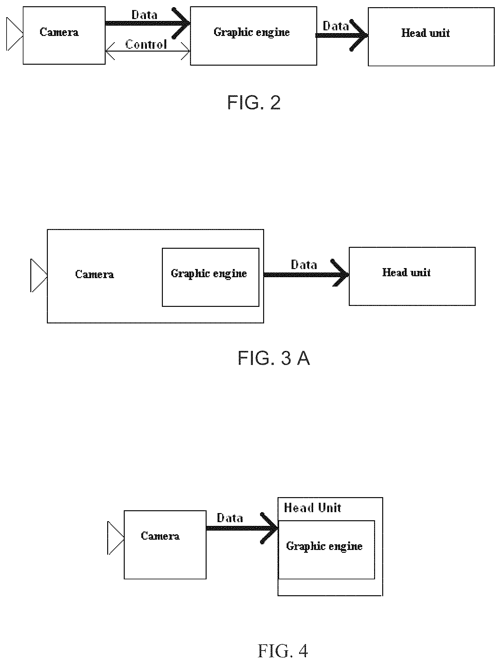
FIG. 2 is a schematic of an automotive vision camera for providing data and getting controlled from an image processing control device, with the image processing control device providing image data to a head unit or other display device;
FIG. 3A is a schematic of an automotive vision camera with graphic processing board incorporated within the same device, whereby the processed image data gets provided to a head unit or other display device;
FIG. 3B is a schematic of an automotive vision camera with graphic processing board incorporated within the same device, whereby the processed image data gets provided to a head unit or other display device and with the camera being controlled via a back channel;
FIG. 3C is a schematic of an automotive vision camera with graphic processing board incorporated within the same device, whereby the processed image data gets provided to a head unit or other display device and with an additional bidirectional channel for exchanging control data or parameter;
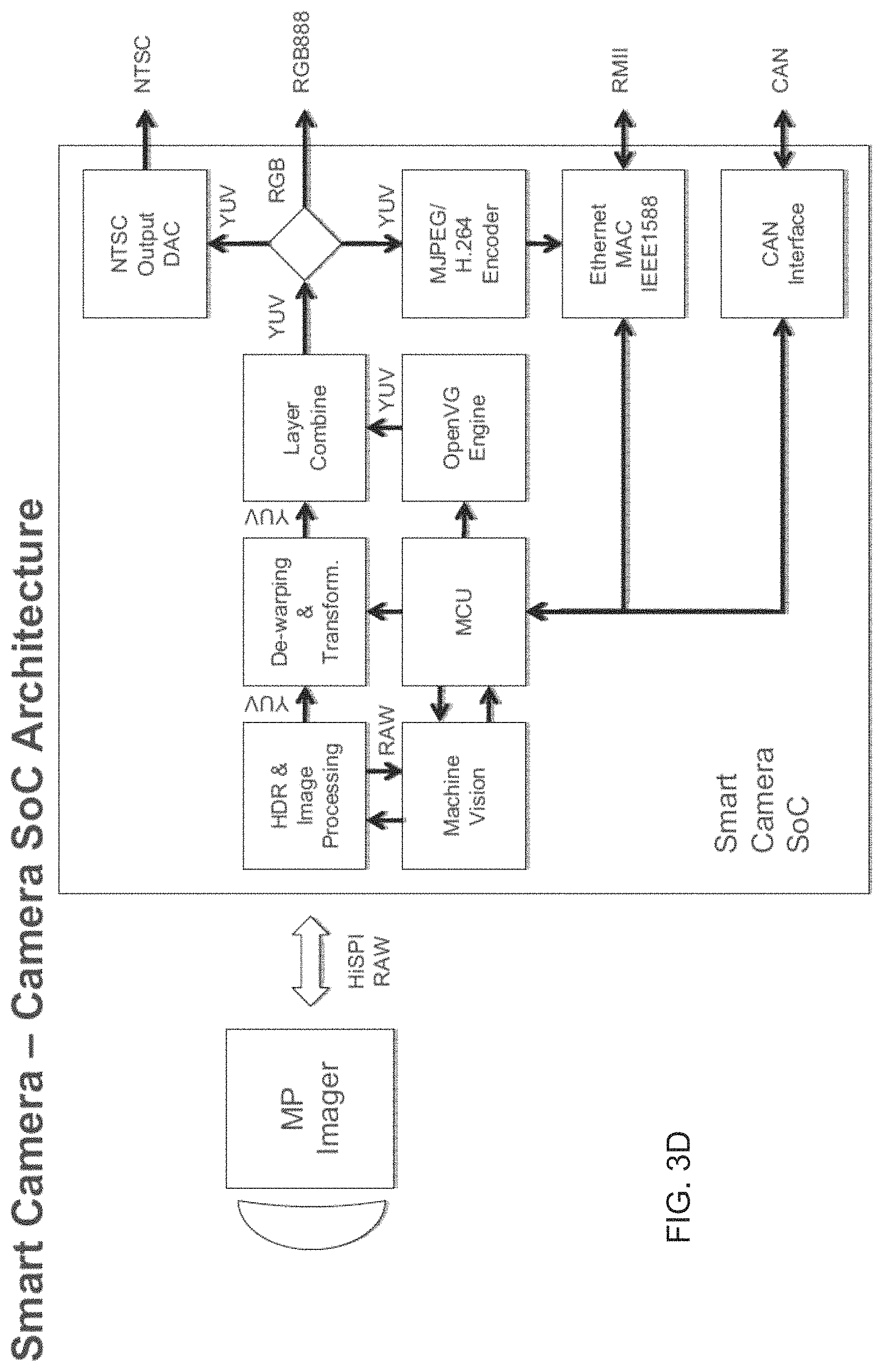
FIG. 3D is a schematic of an example of a graphic processing architecture solution embedded into an automotive vision camera (system on chip), whereby the processed image data is provided to a head unit or other display device by at least one channel but maybe two in parallel to different output bus interfaces for the camera features, where the busses may be used mono-directional or semi-directional (beside RGB888 and NTSC) for control, and shown with RMII, but RGMII may be used alternatively;
FIG. 4 is a schematic of an automotive vision camera that provides mostly raw image data to the head unit, which is carrying out any kind of graphic processing, and there is no communication channel for data from the head unit to the camera, either directly or via gateways, in accordance with the present invention;
FIG. 5A is a schematic of an automotive vision camera system of the present invention with graphic processing incorporated within the head unit by hardware and software, with raw image data (directly) provided to a head unit or other display device for further image processing, and with an additional bidirectional channel for exchanging control data or parameter;
FIG. 5B is a schematic of an automotive vision camera system of the present invention with graphic processing incorporated within the head unit by hardware and software, with raw image data (directly) provided to a head unit or other display device for further image processing, and with the camera being controlled via a back channel;
FIG. 6 is a schematic of an automotive vision camera system of the present invention with graphic processing incorporated within the head unit, and with raw image data provided to a head unit or other display device for further image processing, and with the image data transferred via different busses linked by a bus gateway, and with the camera being controlled via a back channel (which may comprise one bidirectional channel);
FIG. 7 is a schematic of an automotive vision camera system of the present invention with graphic processing incorporated within the head unit, and with raw image data provided to a head unit or other display device for further image processing, and with the image data transferred via different busses linked by a bus gateway, and with the camera control back channel established via bus gateway (which may comprise a bidirectional channel on one or both bus systems);
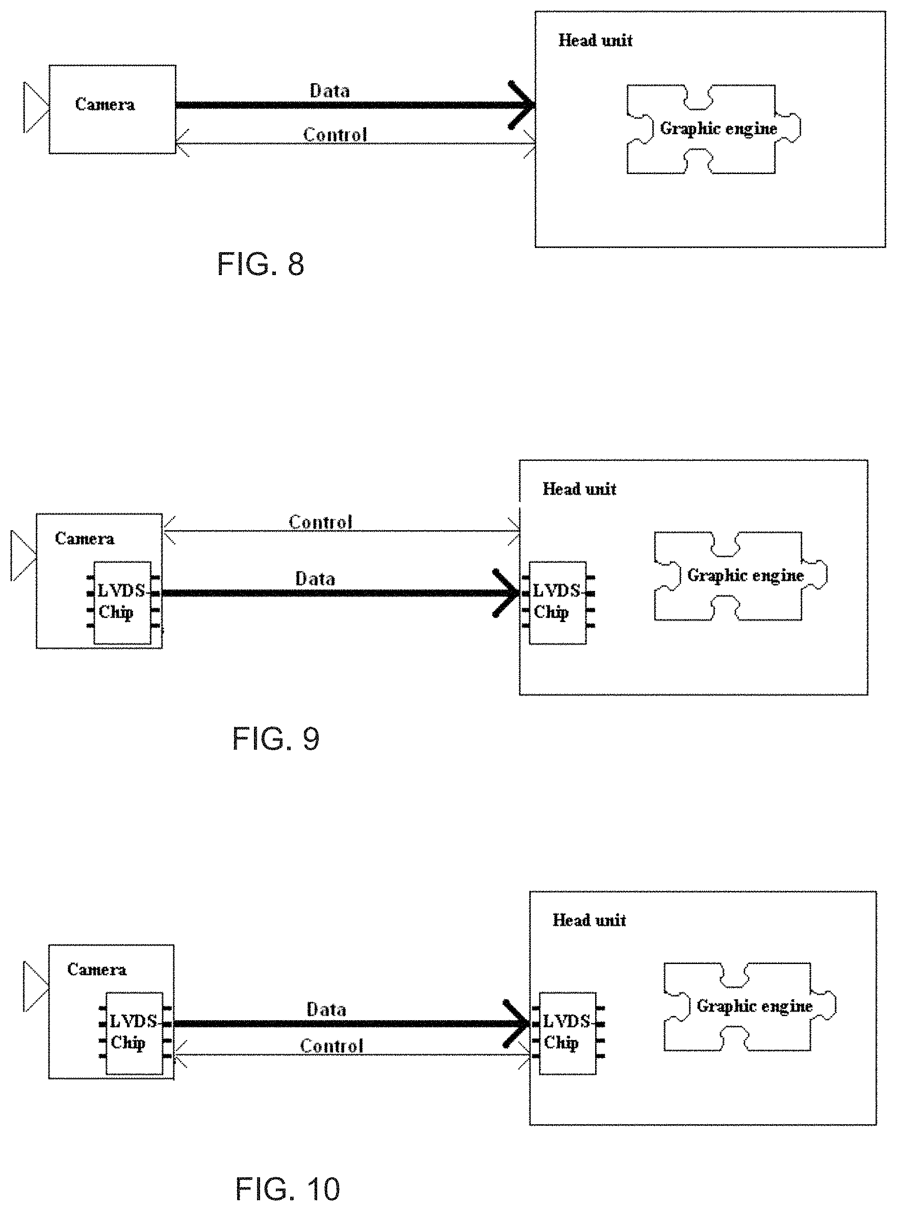
FIG. 8 is a schematic of an automotive vision camera, which provides almost raw data to the head unit or other display device and has a control channel which might be any kind of data line or bus, and with the graphic engine (or the image processing) running as a routine on the head unit or other display device, in accordance with the present invention;
FIG. 9 is a schematic of an automotive vision system according to FIG. 8, which uses LVDS/Ethernet as an Image data transfer channel, in accordance with the present invention;
FIG. 10 is a schematic of an automotive vision system according to FIGS. 8 and 9, which uses LVDS/Ethernet as a bidirectional control channel and an image data transfer channel, in accordance with the present invention;
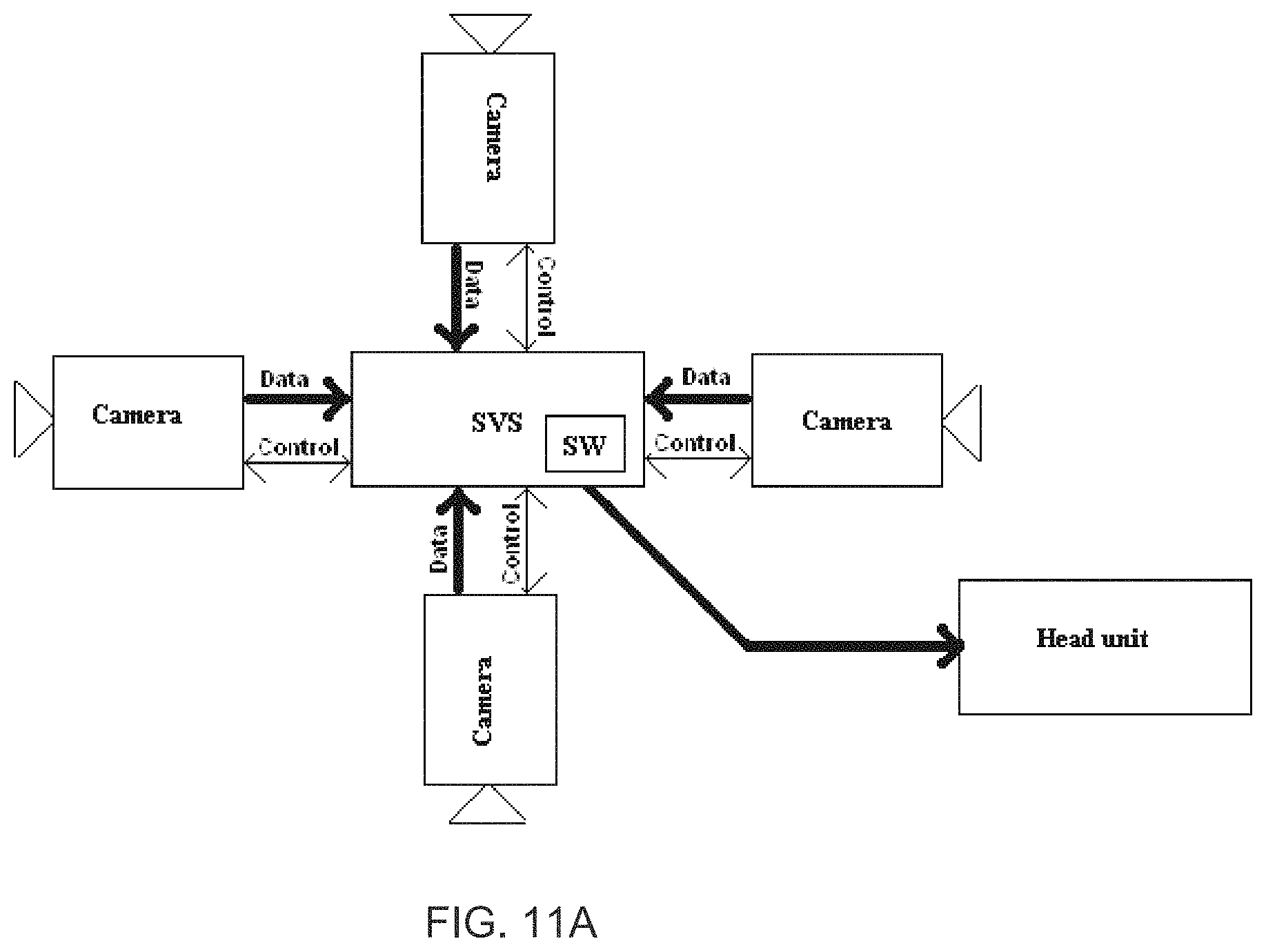
FIG. 11A is a schematic of an automotive vision multi camera architecture, where all cameras are controlled by one control/image data processing device, and where the image data processing device sends processed image data to the head unit or other display device;
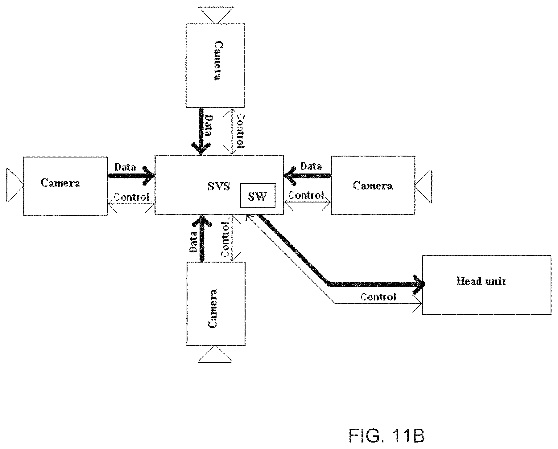
FIG. 11B is a schematic of an automotive vision multi camera architecture, where all of the system cameras are controlled by one control/image data processing device, and where the image data processing device sends processed image data to the head unit or other display device, with an additional mono-directional or bidirectional channel for exchanging control data or parameter with the display device;
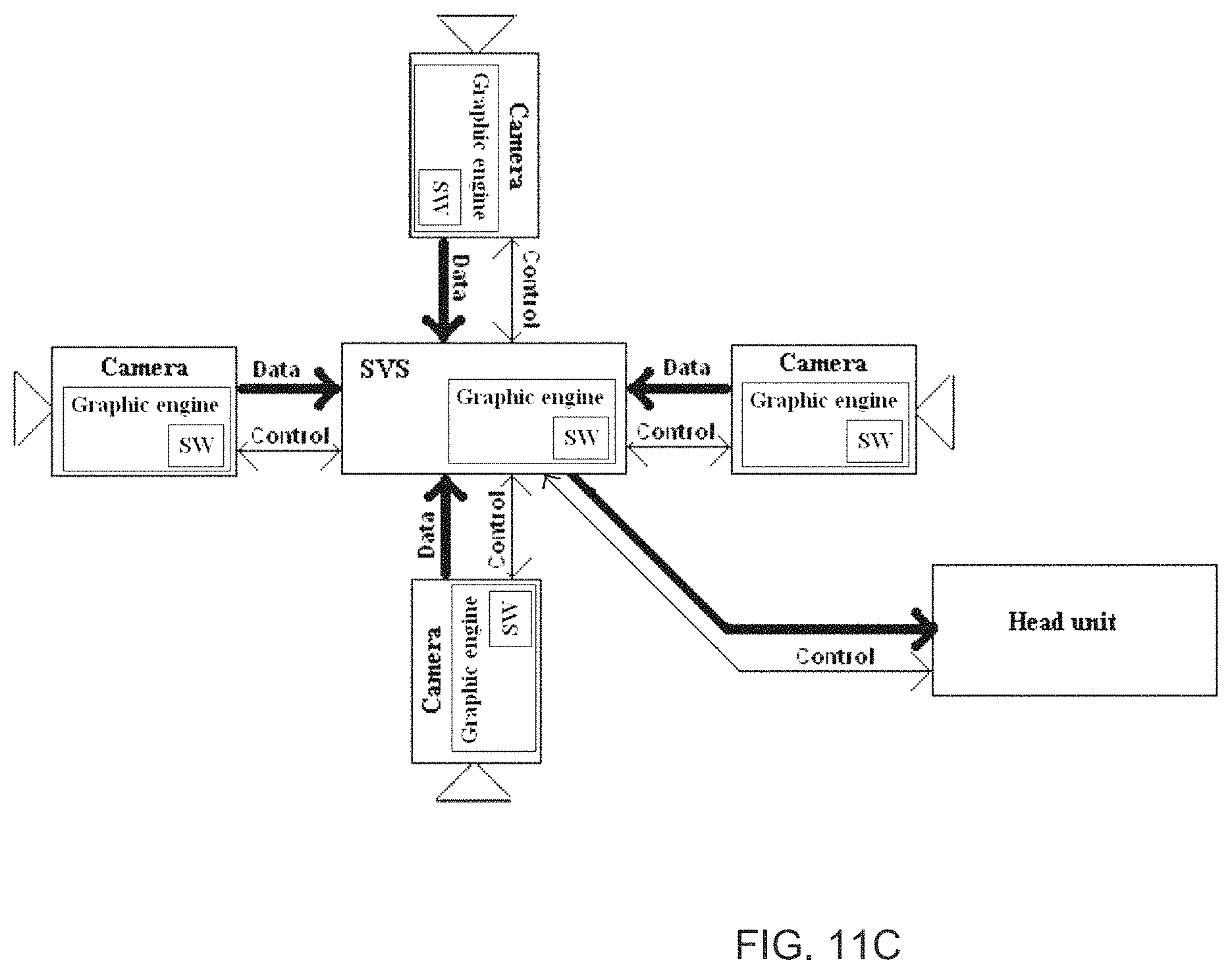
FIG. 11C is a schematic of an automotive vision multi (smart) camera architecture, where the cameras incorporate one part of the image data processing chain and the control device processes a second or alternative part of the image data processing, and where the image data processing device sends processed image data to the head unit or other display device;
FIG. 11D is a schematic of an automotive vision multi (smart) camera architecture, where the cameras incorporate one part of the image data processing chain and the control device processes a second or alternative part of the image data processing, and where the image data processing device sends processed or raw image data to the head unit or other display device, which processes a third or alternative part of the image data processing;
FIG. 11E is a schematic of an automotive vision multi (smart) camera architecture, where the cameras incorporate one part of the image data processing chain and the head unit or other display device processes a second or alternative part of the image data processing, and where the image data and controls from and to the cameras are collected and/or transferred to the head unit or other display device by a router;
FIG. 11F is a schematic of an automotive vision multi camera architecture where the cameras send almost raw data over a router to a head unit or other display device via monodirectional data lines or bus channel, where the data may be compressed by the cameras or by the router before sending;
FIG. 12A is a schematic of an automotive vision multi camera architecture, where all of the cameras provide almost raw data to the head unit or other display device direct without having a central image processing device or router in between and have a control channel for exchanging control data or parameter with the head unit or display device which might be any kind of data line or bus, and with the graphic engine (or the image processing) running on an integrated hardware on the head unit or other display device, in accordance with the present invention;
FIG. 12B is a schematic of an automotive vision multi camera architecture, where all of the cameras provide almost raw data to the head unit or other display device direct without having a central image processing device or router in between and have a monodirectional camera control channel which may comprise any kind of data line or bus, and with the graphic engine (or the image processing) running on an integrated hardware on the head unit or other display device, in accordance with the present invention;
FIG. 12C is a schematic of an automotive vision multi camera architecture, where some or all of the cameras provide almost raw data to the head unit or other display device direct without having a central image processing or router device in between using monodirectional data channels as like NTSC and with the graphic engine (or the image processing) running on an integrated hardware on the head unit or other display device, in accordance with the present invention;
FIG. 13 is a schematic of an automotive vision multi camera architecture, where all of the cameras providing almost raw data to the head unit or other display device and with the graphic engine (or the image processing) running as a routine mainly on the CPU, without having dedicated vehicle camera image processing hardware on the head unit or other display device, in accordance with the present invention;
FIG. 14 is a schematic of an automotive vision system according to FIG. 8, with the head unit or other display device conjuncted to a mobile infotainment device or mobile phone or mobile device, and with the graphic engine (or the image processing) running as an `app` (application) on the mobile device, in accordance with the present invention, and with the camera comprising a basic or baseline camera, which has no control input;
FIG. 15 is a schematic of an automotive vision system, with a single camera providing image date to the head unit or other display device, and with the camera controlled via a control channel, and with the head unit carrying communication hardware for communicating with the camera, and with the vision software or vision applications utilizing the incoming data for further (high level) processing, in accordance with the present invention;
FIG. 16 is a schematic of an automotive vision system according to FIGS. 8 and 14, with the head unit or other display device conjuncted to a mobile infotainment device or mobile phone or mobile device, and with the graphic engine (or the image processing) running as an `app` (application) on the mobile device, in accordance with the present invention, and with a single camera in use that is controlled via a control channel;
FIG. 17 is a schematic of an automotive vision system according to FIG. 16, with the graphic engine (or the image processing) running as an `app` (application) on the mobile device, and with the software additionally computing additional parameters and with the steering angle taken into account, which may be used for processing graphical steering aid overlays to a rear camera image while backing up the vehicle, in accordance with the present invention;
FIG. 18 is a schematic of an automotive vision system according to FIG. 17, with the system processing image data captured by more than one camera and by other driver assistant system sources such as ultrasound sensors, Radar sensors, infrared and visual cameras, Lidar or Laser sensors, in accordance with the present invention, with the graphic engine (or the image processing) running as an `app` (application) on the mobile device;
FIG. 19A is a schematic of an automotive vision system according to FIGS. 8 to 18, with the system using apps certified by according certification boards of governmental organs or mobile device companies and/or OEMs, in accordance with the present invention;
FIG. 19B is a schematic of an automotive vision/driver assistant system according to FIGS. 18 and 19A, with the system is connected to a mobile phone which transmits control commands to vehicle inherent devices (as like warnings, invasive interaction);
FIG. 20 is a schematic of an automotive vision system having a bus gateway within the path of image raw data between camera and mobile infotainment device or mobile phone, with the back channel to the camera established separately, and with the mobile infotainment device or mobile phone doing the graphic processing, in accordance with the present invention;
FIG. 21 is a schematic of an automotive vision system according to FIG. 16, having non permanently mounted USB based cameras plugged into a USB port that is part of the vehicle's bus architecture that may have bus gateways such as USB to CAN, with the Camera sending images via the USB, in accordance with the present invention;
FIG. 22 is a schematic of an automotive vision system having a bus gateway within the path of image raw data between the camera and head unit or other display device, with the back channel to the camera established separately, and with the head unit doing the graphic processing, in accordance with the present invention;
FIG. 23 is a schematic of an automotive vision system having a bus gateway within the path of image raw data between camera and mobile infotainment device or mobile phone, with the camera control back channel established via the gateways (which may comprise a bidirectional channel on one or both bus systems), and with the mobile device doing the graphic processing, in accordance with the present invention;
FIG. 24 is a schematic of an automotive vision system having non-permanently mounted USB based cameras plugged into any USB port that is part of the vehicle's bus architecture, which might have bus gateways such as USB to CAN, with the Camera sending images via the USB, and with the camera control back channel established via the gateways (which may comprise a bidirectional channel on one or both bus systems), and with the mobile device doing the graphic processing, in accordance with the present invention;
FIG. 25 is a schematic of an automotive vision system having a bus gateway within the path of image raw data between camera and head unit, with the camera control back channel established via the gateways (which may comprise a bidirectional channel on one or both bus systems), and with the mobile device doing the graphic processing, in accordance with the present invention;
FIG. 26A is a schematic of an automotive vision system with a consecutive solution to FIG. 18, where the app visualizes driver assistant functions, and also controls outputs such as driving interventions or active warnings such as steering wheel or foot pedal vibrations, in accordance with the present invention;
FIG. 26B is a schematic of an automotive vision system with the system using apps certified by according certification boards of governmental organs or mobile device companies and/or OEMs, in accordance with the present invention;
FIG. 27 is a schematic of an automotive vision system having a bus gateway within the path of image raw data between camera and head unit, with the back channel to the camera established separately, and with the head unit or other display device doing the graphic processing, with the head unit carrying communication hardware for communicating with the camera, and with the vision software or vision applications utilizing the incoming data for further (high level) processing, which may run on designated image processing hardware, in accordance with the present invention;
FIG. 28 is a schematic of an automotive vision system having a bus gateway within the path of image raw data between camera and head unit, with the camera control back channel established via the gateways (which may comprise a bidirectional channel on one or both bus systems), and with the head unit or other display device doing the graphic processing, and with the vision software or vision applications utilizing the incoming data for further (high level) processing, which may run on designated image processing hardware, and with the head unit carrying commutation hardware for communicating with the camera, in accordance with the present invention;
FIG. 29A is a schematic of an automotive vision system of the present invention, with a graphic engine (or the image processing) running as an `app` (application) or (evtl. additional) software on the head unit/display device's main control or on a graphic hardware, and with the head unit connected to a phone or communication device;
FIG. 29B is a schematic of an automotive vision system of the present invention, with a graphic engine (or the image processing) running as an `app` (application) or (evtl. additional) software on the head unit/display device's main control or on a graphic hardware, with the head unit connected to a phone or communication device and with a wireless camera connected to the head unit via the connection to the phone or communication device and via a wireless communication hardware at or to the phone or communication device;
FIG. 29C is a schematic of an automotive vision system of the present invention, with a graphic engine (or the image processing) running on the head unit/display device's main control or on a graphic hardware, having at least one automotive camera and with a wireless camera connected to the head unit connected via wireless communication to a wireless camera without control loop;
FIG. 29D is a schematic of an automotive vision system of the present invention, with a graphic engine (or the image processing) running on the head unit/display device's main control or on a graphic hardware, having at least one automotive camera and with a wireless camera connected to the head unit connected via wireless communication to a wireless camera with control loop;
FIG. 29E is a schematic of an automotive vision system of the present invention consecutive to FIG. 11, having several vehicle inherent automotive cameras connected to a control device and with a wireless camera connected additionally via wireless communication hardware on the control device to a wireless camera with control loop;
FIG. 29F is a schematic of an automotive vision system of the present invention, with a graphic engine (or the image processing) running on the head unit/display device's main control or on a graphic hardware, having at least one automotive camera and with an external vehicle inherent wireless device connected to the head unit on which wireless camera with control loop is connected;
FIG. 29G is a schematic of an automotive vision or driver assistant system of the present invention, with a graphic engine (or the image processing) running on the head unit/display device's main control or on a graphic hardware, having several automotive cameras connected and with wireless camera connected to the head unit;
FIG. 29H is a schematic of an automotive vision or driver assistant system of the present invention consecutive to FIG. 29G, with a mobile phone or communication device attached additionally;
FIG. 29I is a schematic of an automotive vision system of the present invention consecutive to FIG. 29B, with a first graphic engine (or the image processing) running as an `app` (application) or (evtl. additional) software on the head unit/display device's main control or on a graphic hardware, and with the head unit connected to a phone or communication device and with a wireless camera connected to the head unit via the connection to the phone or communication device and via a wireless communication hardware at the phone or communication device and with a second graphic engine (or the image processing) running as an `app` (application) or (evtl. additional) software on the mobile device executing a first part of the image processing while the graphic engine on the head unit is processing a second or alternative part of image processing;
FIG. 29J is a schematic of an automotive vision system of the present invention consecutive to FIG. 29I, with a first graphic engine (or the image processing) running as an `app` (application) or (evtl. additional) software on the head unit/display device's main control or on a graphic hardware, and with the head unit connected to a phone or communication device and with a wireless camera connected to the head unit via the connection to the phone or communication device and via a wireless communication hardware at the phone or communication device and with a second graphic engine (or the image processing) running as an `app` (application) or (evtl. additional) software on the mobile device executing a first part of the image processing while the graphic engine on the head unit is processing a second or alternative part of image processing, with more than one vehicle inherent cameras, other vision devices, other sensors and other outputs and actuators attached to a common bus or backbone for exchanging data and commands;
FIG. 29K is a schematic of an automotive vision system of the present invention consecutive to FIGS. 29I and 29J, with a graphic engine (or the image processing) running as an `app` (application) or (evtl. additional) software on the head unit/display device's main control or on a graphic hardware, and with a wireless camera connected to the head unit/display device via a wireless communication hardware at it and with more than one vehicle inherent cameras, other vision devices, other sensors and other outputs and actuators attached to a common bus or backbone for exchanging data and commands;
FIG. 29L is a schematic of an automotive vision system of the present invention consecutive to FIG. 29I to 29J, with a graphic engine (or the image processing) running as an `app` (application) or (evtl. additional) software on the head unit/display device's main control or on a graphic hardware, and with a bus or backbone connected to the head unit and with several vehicle inherent cameras connected to the head unit via the back bone and with wireless camera connected via wireless communication to a wireless communication device which is itself to the head unit/display device via the backbone and with other vision devices, other sensors and other outputs and actuators attached to a common bus or backbone for exchanging data and commands;
FIG. 29M is a schematic of an automotive vision system of the present invention consecutive to FIG. 29I to 29L, with the image processing is running as an `app` (application) or (evtl. additional) software or hardware in part on a communication device and in part on a dedicated vehicle inherent image processing device (SVS) and/or in part on a head unit/display device, with the devices interconnected to each other by data lines buses or back bones, and with a wireless camera attached via wireless connection to the communication device, and with the actuators mainly connected to the central display device, and with the central display device optionally displaying data coming from the wireless camera and coming from the vehicle inherent cameras;
FIG. 30 is a schematic of an automotive vision system of the present invention, with the head unit connected to at least one camera and a phone or communication device in accordance with FIG. 29A, and with the image processing software running mainly on the head unit or other display device, wherein the image processing software becomes updated from a remote device by transferring a data container containing an updated version of software;
FIG. 31 is a schematic of an automotive vision system of the present invention, with the head unit or other display device connected to at least one camera and a phone or communication device in accordance with FIG. 29A, and with a bidirectional data channel established between the camera and the head unit, and wherein the image processing software is running mainly on the camera, but there may be parts of image processing software that is running on the head unit or at a mobile `app`, with the image processing software in the camera (and evtl. also these of the head unit and/or communication device) becoming updated from a remote device or communication by transferring a data container containing an updated version of software from the communication device to the camera, preferably over the head unit, and eventually directly via a common bus;
FIG. 32 is a schematic of an automotive vision system of the present invention, where the communication between head units or other display devices and mobile phones may use a layer based model, and such layer based models may be used in the driver assistant and safety vision system's cameras;
FIG. 33 is a schematic of an automotive vision system of the present invention, wherein, similar to the general layer model from FIG. 32, a virtual communication layer comes into use, with the application communication layer communicating via virtual communication layer to other applications which may be located on other devices in a manner as if all applications are local, and showing examples of a communication between applications on a mobile device and those at a head unit equipped with graphic processing hardware and graphic processing applications, with the hardware link comprising data buses or channels such as CAN, LIN, Ethernet, Bluetooth, NFC (Near Field Communication), and/or the like;
FIG. 34 is a schematic of an automotive vision system of the present invention similar to that of FIG. 33, with a virtual communication layer extended over several devices, and with communication between applications on a mobile device, a head unit and a camera, wherein the connection may be capable to exchange image data, camera control, parameters from sensors and other devices, and driver assistant controls and/or the like;
FIG. 35 is a schematic of an automotive vision system that uses data decoders and/or line drivers in automotive vision camera systems, in accordance with the present invention;
FIG. 36 is a schematic of an automotive vision system that uses LVDS/Ethernet data decoders for driving in automotive vision camera images in accordance with the present invention;
FIG. 37 is a schematic of an automotive vision system according to FIGS. 9 and 10, with the LVDS/Ethernet (or other bus) driver chip sharing one device with the imager, and with the optics comprising a separate component, in accordance with the present invention;
FIG. 38 is a schematic of an automotive vision system according to FIG. 37, with the LVDS/Ethernet (or other bus) driver chip sharing one device with the imager, and with the optics incorporated to the substrate to provide a single compact assembly in accordance with the present invention, and with the so called wafer level cameras incorporating the bus driver, with an optical assembly or lens assembly that may comprise a single optic or lens or multiple optics or lenses;
FIG. 39 is a schematic of a vehicle (10) viewed from top down with a one axis trailer (20) hooked on, wherein the trailer has its own rear camera (14a'), which may be connected by wire or wireless to the vehicle's vision devices or a cell phone displaying the area of view (25) of the trailer rear camera on a display or incorporating the image data information on a machine vision assist system in accordance with the present invention;
FIG. 40 is an exemplary view of a vehicle top view when an additional trailer camera (such as of the type shown in the set up of FIG. 39) sends images that are incorporated to the top view of the vehicle's main display device;
FIG. 41 shows an overview of a smart camera suitable for use with a vision system of the present invention;
FIG. 42-44 show view transformation and machine vision capabilities of the smart camera of FIG. 41;
FIG. 45 shows a summary of the various aspects and properties of the unique feature-point based object detection for use with a vision system according the present invention;
FIG. 46 is a schematic showing a possible architecture solution when the invention's processing algorithm are integrated to a smart vehicle camera featuring different output bus interfaces; and
FIGS. 47-65 show various connections and system architecture and other aspects and constructions and features of a smart camera and associated accessories and systems for use with a vision system according the present invention.
DESCRIPTION OF THE PREFERRED EMBODIMENTS
A driver assist system and/or vision system and/or object detection system and/or alert system may operate to capture images exterior of the vehicle and process the captured image data to detect objects at or near the vehicle and in the predicted path of the vehicle, such as to assist a driver of the vehicle in maneuvering the vehicle in a rearward direction. The object detection may utilize detection and analysis of moving vectors representative of objects detected in the field of view of the vehicle camera, in order to determine which detected objects are objects of interest to the driver of the vehicle, such as when the driver of the vehicle undertakes a reversing maneuver.
Referring now to the drawings and the illustrative embodiments depicted therein, a vehicle 10 includes an imaging system or vision system 12 that includes one or more imaging sensors or cameras (such as a rearward facing imaging sensor or camera 14a and/or a forwardly facing camera 14b at the front (or at the windshield) of the vehicle, and/or a sidewardly/rearwardly facing camera 14c, 14b at the sides of the vehicle), which capture images exterior of the vehicle, with the cameras having a lens for focusing images at or onto an imaging array or imaging plane of the camera (FIG. 1). The vision system 12 is operable to process image data captured by the cameras and may provide displayed images at a display device 16 for viewing by the driver of the vehicle. Optionally, the vision system may process image data to detect objects, such as objects to the rear of the subject or equipped vehicle during a reversing maneuver, or such as approaching or following vehicles or vehicles at a side lane adjacent to the subject or equipped vehicle or the like. Optionally, the object detection may utilize detection and analysis of moving vectors representative of objects detected in the field of view of the vehicle camera, in order to determine which detected objects are objects of interest to the driver of the vehicle, such as when the driver of the vehicle undertakes a reversing maneuver (such as by utilizing aspects of the systems described in U.S. provisional applications, Ser. No. 61/605,409, filed Mar. 1, 2012; and Ser. No. 61/563,965, filed Nov. 28, 2011, which are hereby incorporated herein by reference in their entireties.
Vehicle vision systems typically use sophisticated image processing algorithms. For example, either the algorithm runs on a hardware which is integrated to a vision camera or the algorithm runs on an external control device collecting and processing the incoming camera raw data, and then sends a processed image data stream to a display device, cluster or head unit. Vehicle displays vehicle vision systems may be provided at multi-media head units (such as by utilizing aspects of the mirror assemblies described in U.S. Pat. No. 7,937,667, which is hereby incorporated herein by reference in its entirety), and may process several input sources, such that processing power is adapted accordingly. Optionally, a system may visualize and control the apps running on a mobile infotainment device or mobile phone which is connected to or in communication with the head unit, either wirelessly (near field communication, BLUETOOTH.RTM., and the like) or plugged in. It is known to control the app interactively and depending on the driving situation.
The present invention provides a system that delocates the computing load from the camera or separate image control to the head unit or conjuncted or connected mobile device which typically come with high processing performance and are embedded into the display or head unit environment anyway. The system may utilize aspects of the systems described in U.S. Pat. No. 7,697,027 and/or U.S. patent application Ser. No. 13/377,673, filed Dec. 12, 2011, now U.S. Pat. No. 9,036,026, which are hereby incorporated herein by reference in their entireties.
Vision system camera electronics are preferably developed to cost efficient. Due to lower development costs, vision camera systems are typically uniformed as much as possible to lower the number of variants. Also, the complexity is preferably reduced or limited or held as low as possible. Every electronic part that is integrated into cameras produces heat and takes precious space. Simplifying and standardizing of cameras and their interfaces enables use of modern embedding methods, which reduces system costs and enables the shrinking of the camera, which provide customer benefits.
A different or alternative approach is to eliminate dedicated vision system control devices by transferring its functions (intelligence) either into the (smart) cameras or by transferring its functions to the end devices as like the head unit, the (display) cluster, or other display device. By that also the IOs and controls (such as, for example, invasive assistant systems) may be transferred/placed on those devices.
For reducing the cabling costs, there is the trend to use busses/data backbones onto several sensing and actuator devices attached. Some systems may be able to request data direct from another device on the backbone without interaction of the main unit (head unit). This requires at least bus interfaces on some or all nodes and maybe also processors and may require a sophisticated state and priority handling across the devices.
Vehicle development cycles are typically quite long compared to the rush changing infotainment industry. Because of this, infotainment and vehicle driver assistant and safety systems (DAS) outdate quite rapidly. The appearance and functionality is often already a step behind after-market systems when a vehicle inherent or vehicle-based system enters the market. To counter these circumstances, it would be desirable to vehicle manufacturers to keep (DAS) systems up to date.
The present invention provides an economized vehicle vision system architecture that reduces the cost and complexity of the vehicle camera and vision system.
(1) For lowering the number of variants of different car vision camera systems, the inventive solution is to not implement the electronics in a camera or a separate image processing device and may transfer the graphic engine to the head up unit. By avoiding this, the camera electronics can be reduced to the main functionalities for image capturing and own supply power control. Preferably, a simple data transfer interface finds use to send the camera's (raw) data to the head unit (or other image giving/processing end device). On the head unit or other image giving/processing end device the graphic engine (or the image processing) is processed. Other image giving/processing devices may comprise a mirror display within or outside of the passenger compartment, such as a mirror display at the top center region (such as a video mirror utilizing aspects of the displays described in U.S. Pat. Nos. 7,855,755 and/or 7,777,611, which are hereby incorporated herein by reference in their entireties). There it may be sufficient to place image processing tasks, and the hardware and software, when it comes to comparably low sophisticated light balancing, distortion and stitching tasks, may be fed by comparably low performance rear and side cameras. The early state of the art was to capture images and send it over data lines to a display, typically via an analog signal such as an NTSC signal or the like. This was done without controlling or loop controlling the camera. The solution of the present invention also incorporates a control line running from the head unit to the camera. A loop controlling of the camera and the graphic engine (or the image processing) is realized by that. The controlling is necessary for light and color balancing (such as described in PCT Application No. PCT/US2012/063520, filed Nov. 5, 2012, and published on May 16, 2013 as International Publication No. WO 2013/070539, which is hereby incorporated herein by reference in its entirety) and gain control. Also, the gamma correction may be controlled by the back channel. Other control commands may by for sleep/wake up/idle, low high resolution switching, reduced area selection, compression control or triggering a data dump of intrinsic calibration data (such as described in U.S. Pat. No. 7,979,536, which is hereby incorporated herein by reference in its entirety).
(2) Optionally, a continuative idea of the solution of the present invention is to realize the image data stream from the camera to the head unit (or other end device) on a data encoder chip, preferably by a Low Voltage Differential Signal (LVDS) or Ethernet interface, preferably using a mono coaxial cable and Ethernet encoder chips (in the camera and in the head unit). The Data stream would be mono-directional (such as by utilizing aspects of U.S. provisional application 61/537,279, filed Sep. 21, 2011, which is hereby incorporated herein by reference in its entirety).
(3) Optionally, a further continuative idea is that the control line (HU--Cam) may be realized by a CAN/LIN/other car bus interface or just by a single signal line/wire.
(4) Optionally, and as an alternative to (3), above, the control signal may be transferred via the data encoder chip, preferably by LVDS/Ethernet (data line from (2), above) so the interfaces and data stream are bi-directional.
(5) As solution for the graphic engine (or the image processing) (from (1), above) running on the head unit for a mono or multi camera system, processing the camera control, image dewarp, enhancing, adding overlays, DAS functionality and the like, the software could be running on a hardware added to the head unit.
(6) A continuative idea from (5), above, is to have the head unit connected to a phone or communication device and to one or more cameras (see FIG. 29A).
(7) As a continuative idea to (6), above, the image processing software is running primarily on the head unit. The image processing software becomes updated from a remote source or device by transferring a data container containing an updated version of the image processing software. The container is a frame which is made individually for each vehicle communication environment. The content is preferably vehicle type and manufacturer independent, so the content may be substantially standardized to keep the variety low. Preferably, the communication device enables an app to carry the container.
The container may also be transported by an audio (voice) channel, SMS, MMS, DSRC, near field communication, via a pier to pier protocol and/or the like (see FIG. 30). An alternative is to provide updates by a data medium, a removable cable or an OEM's service interface, either connected to a vehicle's port, a head unit's port, a communication device's port or a vision device's port.
(8) In cases where the hardware set up allows bidirectional communication between the head unit and the camera(s) and a phone or communication or between the communication device and the camera(s) directly, there is a continuative idea to (7), above, which may update the camera(s) image processing software by remote transferring data containers via the communication channels mentioned in (7) or by a common bus, or by an OEM service interface within a data container, from the communication device over the head unit to the camera. This may occur at once or step by step. There may be a part of the image processing software at the head unit, and this may be updated as well with the same or a different data container, at the same or another time (see FIG. 31).
(9) An addition solution to (7) and (8), above, is to have data security protocols in place making sure no data in the head unit, camera(s) or communication device or conjuncted system's software becomes overwritten or corrupted by wrong versions or by draft versions, or unauthorized versions, or by incomplete data sets or incompatible data sets, or by pirated versions or data sets, or virulent data sets, and/or the like. This task may also be managed by the data container's functionality.
(10a) The data of (9) preferably have been authorized by an application provider or distributor, the camera or image system software provider or distributer or the according OEM in compliance to the local or worldwide legal or OEM's safety standards and testing procedures for safety relevant software and non-safety relevant software, whichever may apply for the particular application.
(10b) As an additional or alternative solution, the image processing may be done in part on the mobile device or cellular phone or smart phone and in part on the head unit or other display device and/or in part in a dedicated image processing unit (see FIG. 29M).
As an additional aspect to the inventive solution, one of the systems described above may supplement or substitute the vehicle inherent rear camera's image input by an attached (aftermarket) non vehicle inherent camera image. An exemplary use case is shown in FIG. 39, where a trailer camera 14a', which is attached to the rear of a trailer 20, and which camera's image is sent to the vehicle vision system or a non vehicle display and/or communication device (such as a cell phone's display or the like) via wireless communication (such as, for example, via a Bluetooth communication or via a WLAN or NTSC communication or the like). The architecture may be similar to those shown in FIGS. 29B, 29E and 29G-M. In the cases where the vehicle vision system receives the wireless camera image, the vision system is displaying the trailer camera's image as well. The system may switch to use or display the image of the vehicle rear camera 14a, such as for (machine vision) trailer (side) blind spot detection and trailer angle detection. The area where usually the rear camera is placed within top view (mode) may be filled with the image from the wireless camera so as to be seen in the display (FIG. 40). Since the wireless trailer camera 14a' may not be calibrated and some area between the vehicle rear camera 14a and the trailer camera 14a' may not be captured by any camera there may be voids or black bars in the top view images between the areas encompassed by the vehicle inherent cameras and the area encompassed by trailer camera. The trailer camera may be acquired with the trailer, or may be purchased independently (aftermarket) and then attached to the trailer or may be an optional delivery content from the OEM distributer.
(11) Optionally, the system may use layer based models in the communication architecture between head units, actuators, sensors, communication devices, image processing and/or driver assistant devices, and mobile phones, and may use such layer based models in the driver assistant and safety vision system's cameras this might be new (see FIG. 32). The devices may be interconnected by one or more data lines, busses or backbones (see FIG. 29L), or may be interconnected over other devices and or gateways (see FIG. 29M). The proposed model contains an "Application layer" in which the application's semaphores run, a "Middle (soft-)ware" (MW) which adapts to the operation system and provides the communication between the application components, an "Operation System Abstraction Layer" (OSAL) which provides the abstracted base services of the Operation system as like LINUX which has configurable tasks and events and controls the communication behavior. Also, there is a "Run time operation system" (RTOS) which is the operation system itself and the "Board support package" (BSP) which adapts the operation system to the specific hardware.
(12) The present invention provides for DAS systems to establish a virtual communication layer, which expands over several devices having the same layer structure, and is connected via the communication hardware physically. The application communication layer communicates via virtual communication layer to other applications which are located on the same or other devices in a manner as if all applications would be on the local device (see FIGS. 33 and 34). Graphic capturing or processing applications might connect to each other by this. The hardware link may comprise removable ports (mentioned in (7), above), data buses or channels, such as CAN, LIN, LVDS/Ethernet, Bluetooth, NFC (Near Field Communication), and the like.
(13) Using the layer model from (12), above, a continuative idea is to transport data containers (from 7) from one device to the other.
(14) The virtual communication layer may have security tasks as well for doing that.
(15) Over these layers (from (12), above) there may become image data, camera control, parameters from sensors and other devices, driver assistant controls exchanged.
(16) Optionally, and as an alternative to (5), above, the graphic engine (or the image processing) of a mono or multi camera car vision system could be part of the head unit's software in full extend or partially, so a routine which preferably is served in real time may be provided. The processing performance and architecture of the head unit and peripheral interfaces has to be chosen or selected accordingly.
(17) Optionally, and as an alternative solution to (5) and (16), above, the head unit may be conjuncted to or connected to or in communication with a mobile device, such as, for example, a mobile infotainment device or a mobile phone. The graphic engine (or the image processing) may be running as an `app` (application) on the mobile device and processing camera images which are not taken by the mobile phone's cameras but preferably taken or captured by a fixed mounted car vision camera or cameras, a wireless or wired aftermarket camera or cameras or a USB camera or cameras plugged into any USB port that is part of the car integrated bus architecture or other car based plug in bus.
(18) Optionally, and as an additional feature to (17), above, the app used in the mobile device is certified by according certification boards of governmental organs or (mobile device) companies and/or OEMs.
(19) Optionally, and as an additional feature to (17) or (18), above, the vision system's additional functions (value added) may be provided separate to the camera with the software installed on the head unit or on the app conjuncted to the head unit or from a cloud server or the like.
(20) Optionally, and as an additional solution to (19), above, the software (SW) or app may additionally compute additional parameters, and may consider or take into account various parameters, such as the steering angle of the vehicle or the like. This might be used for processing graphical steering aid overlays to a rear cameras displayed images while backing up the vehicle or for other driver assistant systems overlays.
(21) Optionally, and as an additional solution to (19) or (20), above, the SW (app) may additionally compute or process more than one camera, and also other driver assistant system sources like ultrasound sensors, Radar sensors, infrared or visual cameras, Lidar or Laser sensors.
(22) Optionally, and as an additional solution to (19) to (21), above, the app may not just visualize driver assistant functions, but may also control driving interventions or active warnings, such as haptic alerts or the like, such as, for example, steering wheel vibrations or foot pedal vibrations or the like.
(23) Optionally, and as an additional solution to (19) to (22), above, the app may be adaptable for being updated, debugged, licensed, remote controlled, purchased, sold on `app-stores` or the like, leased, time limited tried, reimbursed when given back, transferred, and/or the like. Also, the camera or vision system calibration may be running on the app or as an app.
(24) Optionally, and as a consecutive solution to (4), above, the LVDS/Ethernet (or other bus) driver chip may share one device with the imager. Thus, the present invention may provide a nearly monolytic assembly.
(25) Optionally, and as a consecutive solution to (24), above, and instead of having a lens holder as a separate component, the optics of the camera or imager may be incorporated to the compact, monolytic design of the imager device. The lens assembly or optics may comprise one lens or lens optic or optical element, or a plurality of lenses or lens optics, such as many small ones. So called wafer level cameras are state of the art in automotive applications but also incorporating the bus driver is new to such automotive camera applications.
(26) Optionally, any kind of automotive camera including wafer level cameras from (25) above may comprise a tunable liquid (micro-) lens capable to adapt the focal length of the lens. Optionally, the viewing direction may also be tunable by a microelectronic mechanical (MEM) or other mechanical element, either by turning the camera or a mirror that the camera has in its optical path. Such an assembly may be capable to focus on specific details or objects of interest within the field of view to enhance the performance of the object detection of the driver assistant system. Instead of using wide angle cameras (such as like fish eye lens cameras and the like), a focus tunable camera with a generally longer focus band may be used. The full area may be detectable by `scanning` through all of the extensions of the mechanics' displacement angles. By that the same area as that provided by a fisheye lens may be covered but with the ability to perceive the area much better and evenly. The focus point to objects in the area or field of view may be a degree to determine or at least to estimate the distance between the focused object and the camera's imager (as like the eye of a chameleon does). For example, an exterior viewing camera with a relatively narrow field of view (for example, a horizontal field of view of about 40 degrees) can be mechanically moved rapidly so that its field of view scans or senses or rasters across a wider field of view (for example, a horizontal field of view of about 200 degrees). If this mechanical motion of the principal viewing direction of the subject camera is executed fast enough (for example, if an entire scan can be executed in about 30 ms or lower, video captured by the rastering camera, as displayed to the driver on an in-cabin video screen, will be usable to that driver as the rate of movement of the rastering camera exceeds the rate at which the eye perceives.
Also, if the focus of the camera can be varied, this can be used to estimate or determine distance to an object, such as discussed below. For illustrative purposes, assume that the focus-variable lens has a five meter focal point/length and assume that a person is standing 10 meters away from the subject lens/camera. The image of the person as captured by that camera will be out of focus. Then, as the focal point/length is progressively increased to six meters, then seven meters and then eight meters and then nine meters, the person ten meters away from the camera remains out of focus and comes into focus only when the variable-focus lens is set to have an about ten meter focal point/length. Thus, the distance from the camera can be determined or estimated based on varying the focal point/length of the lens and determining when the imaged object comes into focus in the captured images.
The camera or sensor may comprise any suitable camera or sensor. Optionally, the camera may comprise a "smart camera" that includes the imaging sensor array and associated circuitry and image processing circuitry and electrical connectors and the like as part of a camera module, such as by utilizing aspects of the vision systems described above and shown in FIGS. 41-65.
The vehicle may include any type of sensor or sensors, such as imaging sensors or radar sensors or lidar sensors or ultrasonic sensors or the like. The imaging sensor or camera may capture image data for image processing and may comprise any suitable camera or sensing device, such as, for example, an array of a plurality of photosensor elements arranged in at least 640 columns and 480 rows (at least a 640.times.480 imaging array), with a respective lens focusing images onto respective portions of the array. The photosensor array may comprise a plurality of photosensor elements arranged in a photosensor array having rows and columns. The logic and control circuit of the imaging sensor may function in any known manner, and the image processing and algorithmic processing may comprise any suitable means for processing the images and/or image data. For example, the vision system and/or processing and/or camera and/or circuitry may utilize aspects described in U.S. Pat. Nos. 7,005,974; 5,760,962; 5,877,897; 5,796,094; 5,949,331; 6,222,447; 6,302,545; 6,396,397; 6,498,620; 6,523,964; 6,611,202; 6,201,642; 6,690,268; 6,717,610; 6,757,109; 6,802,617; 6,806,452; 6,822,563; 6,891,563; 6,946,978; 7,859,565; 5,550,677; 5,670,935; 6,636,258; 7,145,519; 7,161,616; 7,230,640; 7,248,283; 7,295,229; 7,301,466; 7,592,928; 7,881,496; 7,720,580; 7,038,577; 6,882,287; 5,929,786 and/or 5,786,772, and/or PCT Application No. PCT/US2010/047256, filed Aug. 31, 2010 and published Mar. 10, 2011 as International Publication No. WO 2011/028686 and/or International Publication No. WO 2010/099416, published Sep. 2, 2010, and/or PCT Application No. PCT/US10/25545, filed Feb. 26, 2010 and published Sep. 2, 2010 as International Publication No. WO 2010/099416, and/or PCT Application No. PCT/US2012/048800, filed Jul. 30, 2012, and published on Feb. 7, 2013 as International Publication No. WO 2013019707, and/or PCT Application No. PCT/US2012/048110, filed Jul. 25, 2012, and published Jan. 31, 2013 as International Publication No. WO 2013016409, and/or PCT Application No. PCT/CA2012/000378, filed Apr. 25, 2012, and published on Nov. 1, 2012 as International Publication No. WO 2012145822, and/or PCT Application No. PCT/US2012/056014, filed Sep. 19, 2012, and published on Mar. 28, 2013 as International Publication No. WO 2013043661, and/or PCT Application No. PCT/US12/57007, filed Sep. 25, 2012, and published on Apr. 4, 2013 as International Publication No. WO 2013/048994, and/or PCT Application No. PCT/US2012/061548, filed Oct. 24, 2012, and published May 2, 2013 as International Publication No. WO 2013063014, and/or PCT Application No. PCT/US2012/062906, filed Nov. 1, 2012, and published May 10, 2013 as International Publication No. WO 2013067083, and/or PCT Application No. PCT/US2012/063520, filed Nov. 5, 2012, and published May 16, 2013 as International Publication No. WO 2013070539, and/or PCT Application No. PCT/US2012/064980, filed Nov. 14, 2012, and published May 23, 2013 as International Publication No. WO 2013074604, and/or U.S. patent application Ser. No. 13/660,306, filed Oct. 25, 2012, now U.S. Pat. No. 9,146,898; Ser. No. 13/653,577, filed Oct. 17, 2012, now U.S. Pat. No. 9,174,574; and/or Ser. No. 13/534,657, filed Jun. 27, 2012, and published on Jan. 3, 2013 as U.S. Patent Publication No. US-2013-0002873, and/or U.S. provisional applications, Ser. No. 61/710,924, filed Oct. 8, 2012; Ser. No. 61/696,416, filed Sep. 4, 2012; Ser. No. 61/682,995, filed Aug. 14, 2012; Ser. No. 61/682,486, filed Aug. 13, 2012; Ser. No. 61/680,883, filed Aug. 8, 2012; Ser. No. 61/678,375, filed Aug. 1, 2012; Ser. No. 61/676,405, filed Jul. 27, 2012; Ser. No. 61/666,146, filed Jun. 29, 2012; Ser. No. 61/653,665, filed May 31, 2012; Ser. No. 61/653,664, filed May 31, 2012; Ser. No. 61/648,744, filed May 18, 2012; Ser. No. 61/624,507, filed Apr. 16, 2012; Ser. No. 61/616,126, filed Mar. 27, 2012; Ser. No. 61/615,410, filed Mar. 26, 2012; Ser. No. 61/613,651, filed Mar. 21, 2012; Ser. No. 61/607,229, filed Mar. 6, 2012; Ser. No. 61/602,878, filed Feb. 24, 2012; Ser. No. 61/602,876, filed Feb. 24, 2012; Ser. No. 61/600,205, filed Feb. 17, 2012; Ser. No. 61/588,833, filed Jan. 20, 2012; Ser. No. 61/583,381, filed Jan. 5, 2012; Ser. No. 61/570,017, filed Dec. 13, 2011; Ser. No. 61/568,791, filed Dec. 9, 2011; Ser. No. 61/567,446, filed Dec. 6, 2011; and/or Ser. No. 61/567,150, filed Dec. 6, 2011, which are all hereby incorporated herein by reference in their entireties. The system may communicate with other communication systems via any suitable means, such as by utilizing aspects of the systems described in PCT Application No. PCT/US10/038477, filed Jun. 14, 2010, and/or U.S. patent application Ser. No. 13/202,005, filed Aug. 17, 2011, now U.S. Pat. No. 9,126,525, which are hereby incorporated herein by reference in their entireties.
The imaging device and control and image processor and any associated illumination source, if applicable, may comprise any suitable components, and may utilize aspects of the cameras and vision systems described in U.S. Pat. Nos. 5,550,677; 5,877,897; 6,498,620; 5,670,935; 5,796,094; 6,396,397; 6,806,452; 6,690,268; 7,005,974; 7,123,168; 7,004,606; 6,946,978; 7,038,577; 6,353,392; 6,320,176; 6,313,454 and 6,824,281, and/or International Publication No. WO 2010/099416, published Sep. 2, 2010, and/or PCT Application No. PCT/US10/47256, filed Aug. 31, 2010 and published Mar. 10, 2011 as International Publication No. WO 2011/028686, and/or U.S. patent application Ser. No. 12/508,840, filed Jul. 24, 2009, and published Jan. 28, 2010 as U.S. Pat. Publication No. US 2010-0020170, and/or PCT Application No. PCT/US2012/048110, filed Jul. 25, 2012, and published Jan. 31, 2013 as International Publication No. WO 2013016409, and/or U.S. patent application Ser. No. 13/534,657, filed Jun. 27, 2012, and published Jan. 3, 2013 as U.S. Patent Publication No. US-2013-0002873, which are all hereby incorporated herein by reference in their entireties. The camera or cameras may comprise any suitable cameras or imaging sensors or camera modules, and may utilize aspects of the cameras or sensors described in U.S. patent application Ser. No. 12/091,359, filed Apr. 24, 2008 and published Oct. 1, 2009 as U.S. Publication No. US-2009-0244361, and/or Ser. No. 13/260,400, filed Sep. 26, 2011, now U.S. Pat. Nos. 8,542,451, and/or 7,965,336 and/or 7,480,149, which are hereby incorporated herein by reference in their entireties. The imaging array sensor may comprise any suitable sensor, and may utilize various imaging sensors or imaging array sensors or cameras or the like, such as a CMOS imaging array sensor, a CCD sensor or other sensors or the like, such as the types described in U.S. Pat. Nos. 5,550,677; 5,670,935; 5,760,962; 5,715,093; 5,877,897; 6,922,292; 6,757,109; 6,717,610; 6,590,719; 6,201,642; 6,498,620; 5,796,094; 6,097,023; 6,320,176; 6,559,435; 6,831,261; 6,806,452; 6,396,397; 6,822,563; 6,946,978; 7,339,149; 7,038,577; 7,004,606 and/or 7,720,580, and/or U.S. patent application Ser. No. 10/534,632, filed May 11, 2005, now U.S. Pat. No. 7,965,336; and/or PCT Application No. PCT/US2008/076022, filed Sep. 11, 2008 and published Mar. 19, 2009 as International Publication No. WO 2009/036176, and/or PCT Application No. PCT/US2008/078700, filed Oct. 3, 2008 and published Apr. 9, 2009 as International Publication No. WO 2009/046268, which are all hereby incorporated herein by reference in their entireties.
The camera module and circuit chip or board and imaging sensor may be implemented and operated in connection with various vehicular vision-based systems, and/or may be operable utilizing the principles of such other vehicular systems, such as a vehicle headlamp control system, such as the type disclosed in U.S. Pat. Nos. 5,796,094; 6,097,023; 6,320,176; 6,559,435; 6,831,261; 7,004,606; 7,339,149 and/or 7,526,103, which are all hereby incorporated herein by reference in their entireties, a rain sensor, such as the types disclosed in commonly assigned U.S. Pat. Nos. 6,353,392; 6,313,454; 6,320,176 and/or 7,480,149, which are hereby incorporated herein by reference in their entireties, a vehicle vision system, such as a forwardly, sidewardly or rearwardly directed vehicle vision system utilizing principles disclosed in U.S. Pat. Nos. 5,550,677; 5,670,935; 5,760,962; 5,877,897; 5,949,331; 6,222,447; 6,302,545; 6,396,397; 6,498,620; 6,523,964; 6,611,202; 6,201,642; 6,690,268; 6,717,610; 6,757,109; 6,802,617; 6,806,452; 6,822,563; 6,891,563; 6,946,978 and/or 7,859,565, which are all hereby incorporated herein by reference in their entireties, a trailer hitching aid or tow check system, such as the type disclosed in U.S. Pat. No. 7,005,974, which is hereby incorporated herein by reference in its entirety, a reverse or sideward imaging system, such as for a lane change assistance system or lane departure warning system or for a blind spot or object detection system, such as imaging or detection systems of the types disclosed in U.S. Pat. Nos. 7,720,580; 7,038,577; 5,929,786 and/or 5,786,772, and/or U.S. patent application Ser. No. 11/239,980, filed Sep. 30, 2005, now U.S. Pat. No. 7,881,496, and/or U.S. provisional applications, Ser. No. 60/628,709, filed Nov. 17, 2004; Ser. No. 60/614,644, filed Sep. 30, 2004; Ser. No. 60/618,686, filed Oct. 14, 2004; Ser. No. 60/638,687, filed Dec. 23, 2004, which are hereby incorporated herein by reference in their entireties, a video device for internal cabin surveillance and/or video telephone function, such as disclosed in U.S. Pat. Nos. 5,760,962; 5,877,897; 6,690,268 and/or 7,370,983, and/or U.S. patent application Ser. No. 10/538,724, filed Jun. 13, 2005 and published Mar. 9, 2006 as U.S. Publication No. US-2006-0050018, which are hereby incorporated herein by reference in their entireties, a traffic sign recognition system, a system for determining a distance to a leading or trailing vehicle or object, such as a system utilizing the principles disclosed in U.S. Pat. Nos. 6,396,397 and/or 7,123,168, which are hereby incorporated herein by reference in their entireties, and/or the like.
Optionally, the circuit board or chip may include circuitry for the imaging array sensor and or other electronic accessories or features, such as by utilizing compass-on-a-chip or EC driver-on-a-chip technology and aspects such as described in U.S. Pat. Nos. 7,255,451 and/or 7,480,149; and/or U.S. patent application Ser. No. 11/226,628, filed Sep. 14, 2005 and published Mar. 23, 2006 as U.S. Publication No. US-2006-0061008, and/or Ser. No. 12/578,732, filed Oct. 14, 2009, now U.S. Pat. No. 9,487,144, which are hereby incorporated herein by reference in their entireties.
Optionally, the vision system may include a display for displaying images captured by one or more of the imaging sensors for viewing by the driver of the vehicle while the driver is normally operating the vehicle. Optionally, for example, the vision system may include a video display device disposed at or in the interior rearview mirror assembly of the vehicle, such as by utilizing aspects of the video mirror display systems described in U.S. Pat. No. 6,690,268 and/or U.S. patent application Ser. No. 13/333,337, filed Dec. 21, 2011, now U.S. Pat. No. 9,264,672, which are hereby incorporated herein by reference in their entireties. The video mirror display may comprise any suitable devices and systems and optionally may utilize aspects of the compass display systems described in U.S. Pat. Nos. 7,370,983; 7,329,013; 7,308,341; 7,289,037; 7,249,860; 7,004,593; 4,546,551; 5,699,044; 4,953,305; 5,576,687; 5,632,092; 5,677,851; 5,708,410; 5,737,226; 5,802,727; 5,878,370; 6,087,953; 6,173,508; 6,222,460; 6,513,252 and/or 6,642,851, and/or European patent application, published Oct. 11, 2000 under Publication No. EP 0 1043566, and/or U.S. patent application Ser. No. 11/226,628, filed Sep. 14, 2005 and published Mar. 23, 2006 as U.S. Publication No. US-2006-0061008, which are all hereby incorporated herein by reference in their entireties. Optionally, the video mirror display screen or device may be operable to display images captured by a rearward viewing camera of the vehicle during a reversing maneuver of the vehicle (such as responsive to the vehicle gear actuator being placed in a reverse gear position or the like) to assist the driver in backing up the vehicle, and optionally may be operable to display the compass heading or directional heading character or icon when the vehicle is not undertaking a reversing maneuver, such as when the vehicle is being driven in a forward direction along a road (such as by utilizing aspects of the display system described in PCT Application No. PCT/US2011/056295, filed Oct. 14, 2011 and published Apr. 19, 2012 as International Publication No. WO 2012/051500, which is hereby incorporated herein by reference in its entirety).
Optionally, the vision system (utilizing the forward facing camera and a rearward facing camera and other cameras disposed at the vehicle with exterior fields of view) may be part of or may provide a display of a top-down view or birds-eye view system of the vehicle or a surround view at the vehicle, such as by utilizing aspects of the vision systems described in PCT Application No. PCT/US10/25545, filed Feb. 26, 2010 and published on Sep. 2, 2010 as International Publication No. WO 2010/099416, and/or PCT Application No. PCT/US10/47256, filed Aug. 31, 2010 and published Mar. 10, 2011 as International Publication No. WO 2011/028686, and/or PCT Application No. PCT/US2011/062834, filed Dec. 1, 2011 and published Jun. 7, 2012 as International Publication No. WO 2012/075250, and/or PCT Application No. PCT/US2012/048993, filed Jul. 31, 2012, and published Feb. 7, 2013 as International Publication No. WO 2013019795, and/or PCT Application No. PCT/US11/62755, filed Dec. 1, 2011 and published Jun. 7, 2012 as International Publication No. WO 2012-075250, and/or PCT Application No. PCT/CA2012/000378, filed Apr. 25, 2012, and published Nov. 1, 2012 as International Publication No. WO 2012145822, and/or U.S. patent application Ser. No. 13/333,337, filed Dec. 21, 2011, now U.S. Pat. No. 9,264,672, and/or U.S. provisional applications, Ser. No. 61/615,410, filed Mar. 26, 2012; Ser. No. 61/588,833, filed Jan. 20, 2012; Ser. No. 61/570,017, filed Dec. 13, 2011; and/or Ser. No. 61/568,791, filed Dec. 9, 2011, which are hereby incorporated herein by reference in their entireties.
Optionally, a video mirror display may be disposed rearward of and behind the reflective element assembly and may comprise a display such as the types disclosed in U.S. Pat. Nos. 5,530,240; 6,329,925; 7,855,755; 7,626,749; 7,581,859; 7,446,650; 7,370,983; 7,338,177; 7,274,501; 7,255,451; 7,195,381; 7,184,190; 5,668,663; 5,724,187 and/or 6,690,268, and/or in U.S. patent application Ser. No. 12/091,525, filed Apr. 25, 2008, now U.S. Pat. No. 7,855,755; Ser. No. 11/226,628, filed Sep. 14, 2005 and published Mar. 23, 2006 as U.S. Publication No. US-2006-0061008; and/or Ser. No. 10/538,724, filed Jun. 13, 2005 and published Mar. 9, 2006 as U.S. Publication No. US-2006-0050018, which are all hereby incorporated herein by reference in their entireties. The display is viewable through the reflective element when the display is activated to display information. The display element may be any type of display element, such as a vacuum fluorescent (VF) display element, a light emitting diode (LED) display element, such as an organic light emitting diode (OLED) or an inorganic light emitting diode, an electroluminescent (EL) display element, a liquid crystal display (LCD) element, a video screen display element or backlit thin film transistor (TFT) display element or the like, and may be operable to display various information (as discrete characters, icons or the like, or in a multi-pixel manner) to the driver of the vehicle, such as passenger side inflatable restraint (PSIR) information, tire pressure status, and/or the like. The mirror assembly and/or display may utilize aspects described in U.S. Pat. Nos. 7,184,190; 7,255,451; 7,446,924 and/or 7,338,177, which are all hereby incorporated herein by reference in their entireties. The thicknesses and materials of the coatings on the substrates of the reflective element may be selected to provide a desired color or tint to the mirror reflective element, such as a blue colored reflector, such as is known in the art and such as described in U.S. Pat. Nos. 5,910,854; 6,420,036 and/or 7,274,501, which are hereby incorporated herein by reference in their entireties.
Optionally, the display or displays and any associated user inputs may be associated with various accessories or systems, such as, for example, a tire pressure monitoring system or a passenger air bag status or a garage door opening system or a telematics system or any other accessory or system of the mirror assembly or of the vehicle or o
D00000
D00001
D00002
D00003
D00004
D00005
D00006
D00007
D00008
D00009
D00010
D00011
D00012
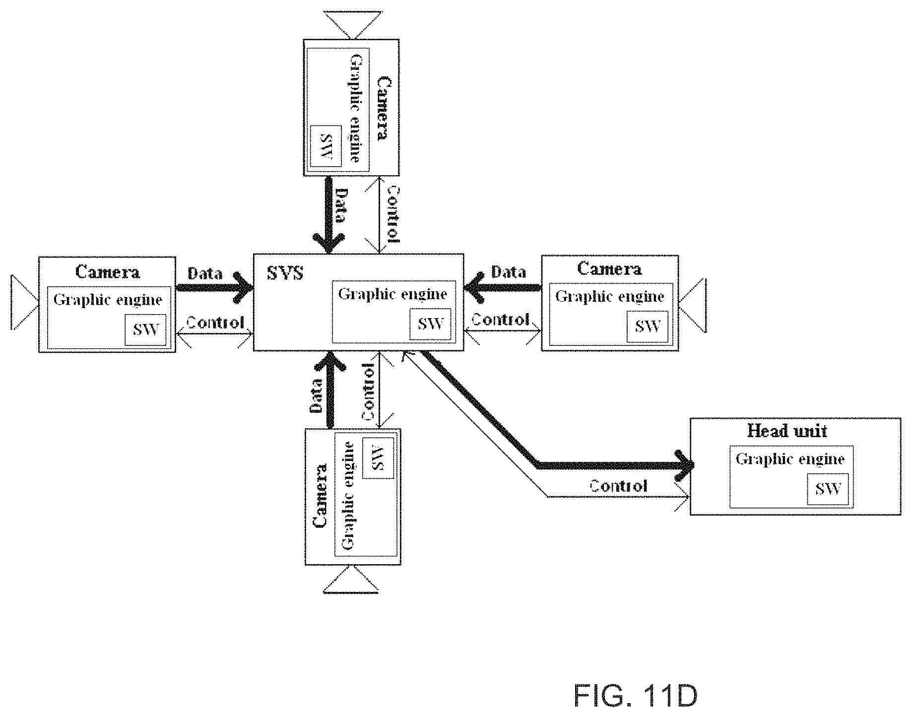
D00013
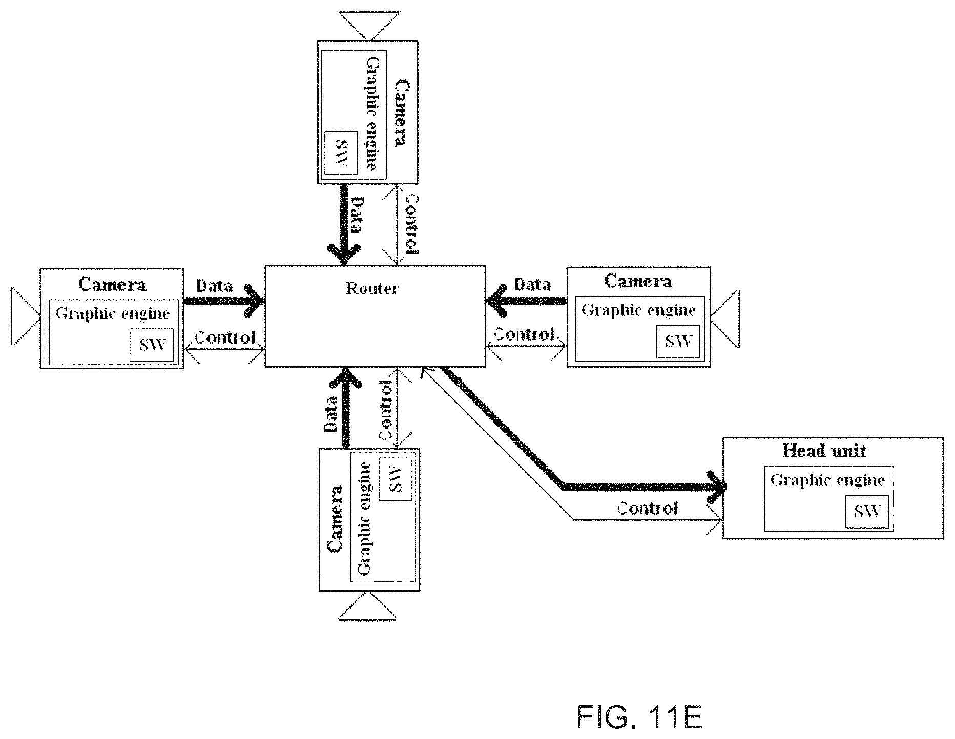
D00014
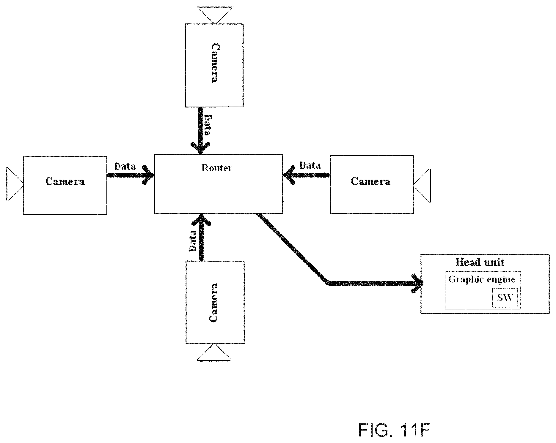
D00015

D00016
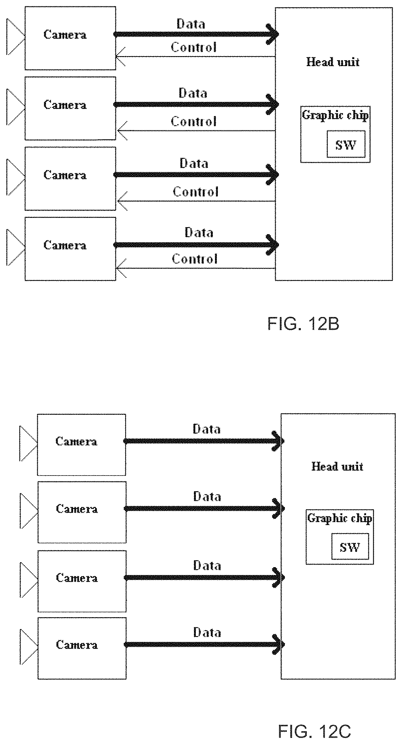
D00017

D00018
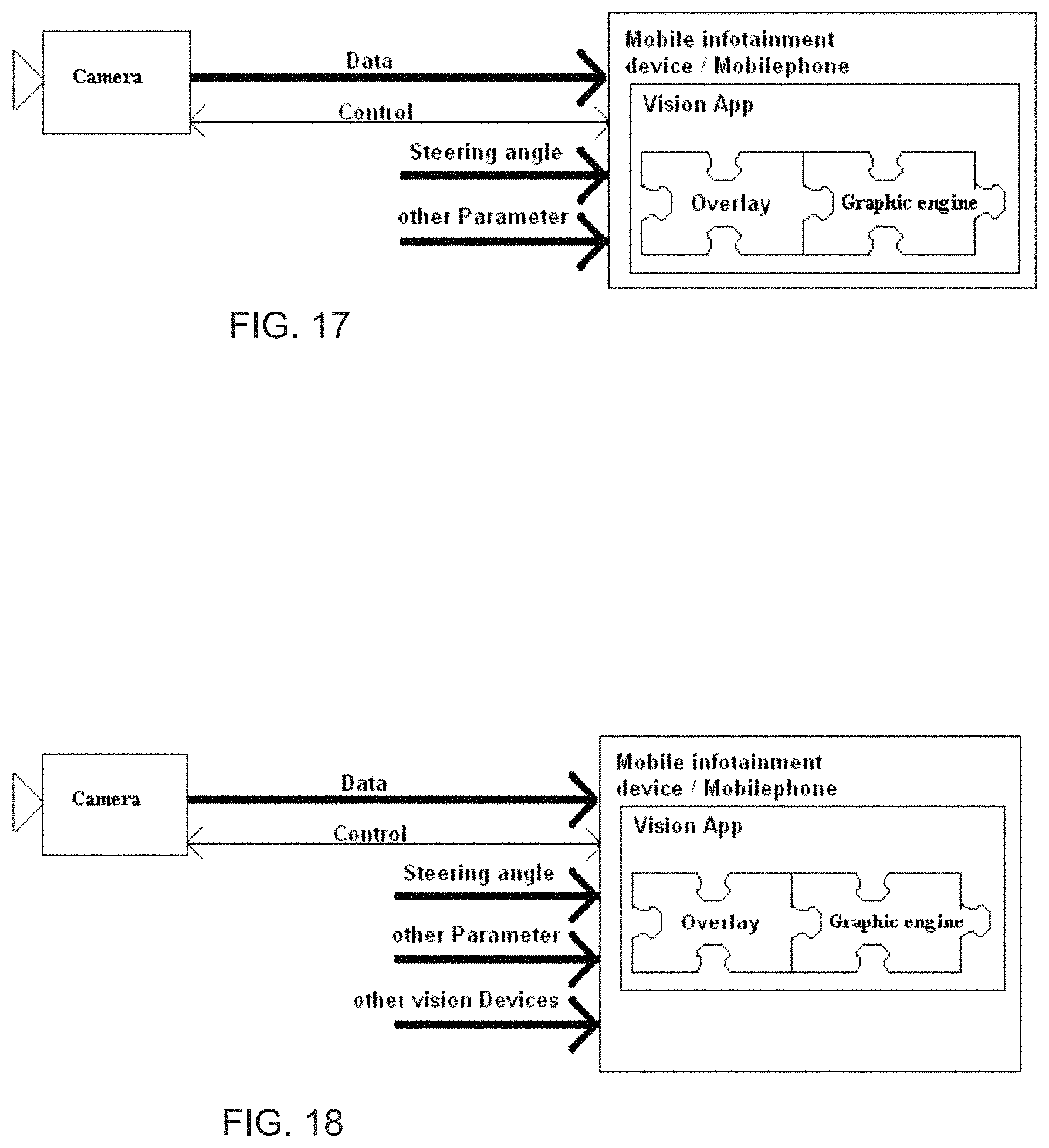
D00019

D00020
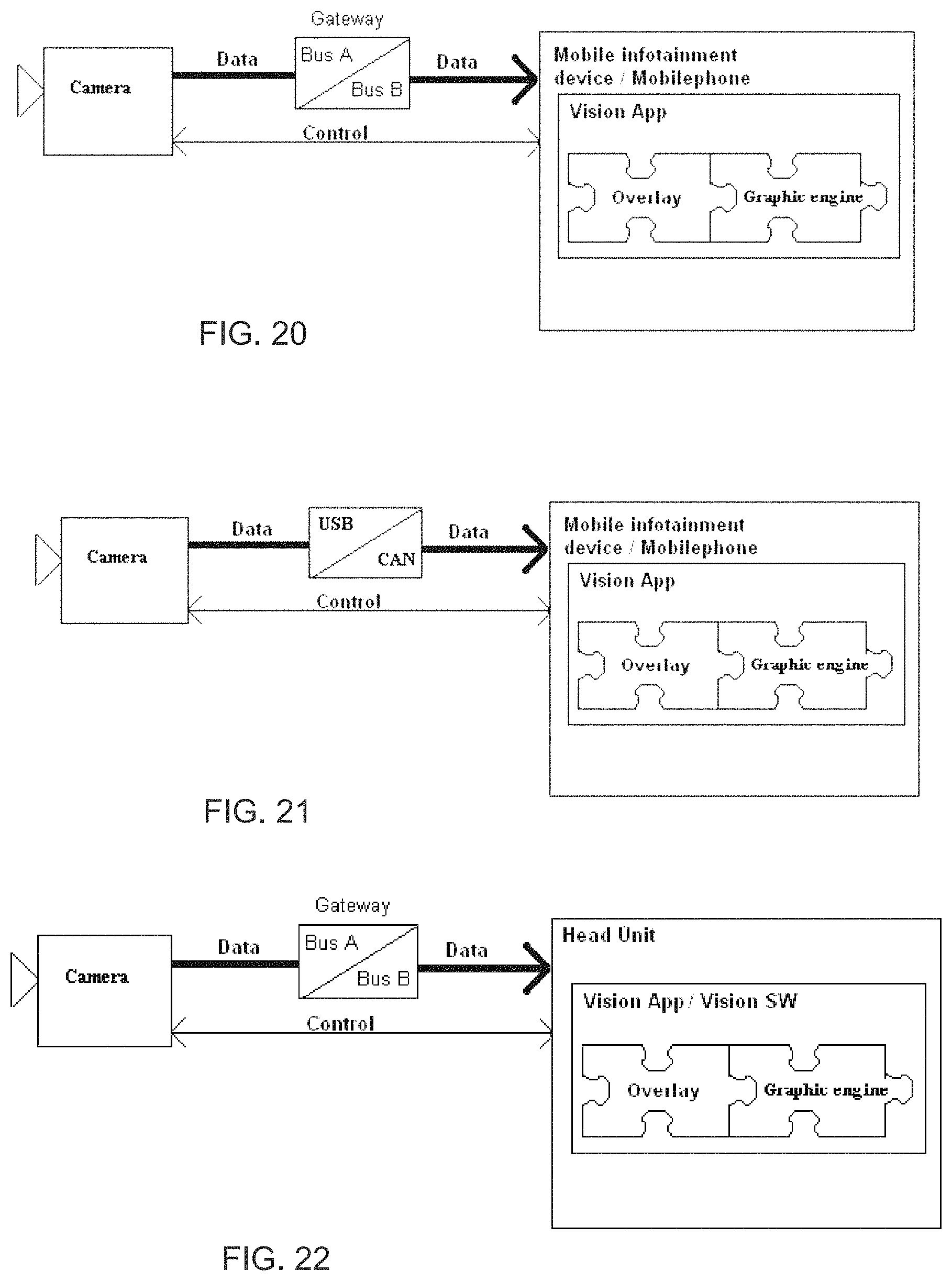
D00021

D00022
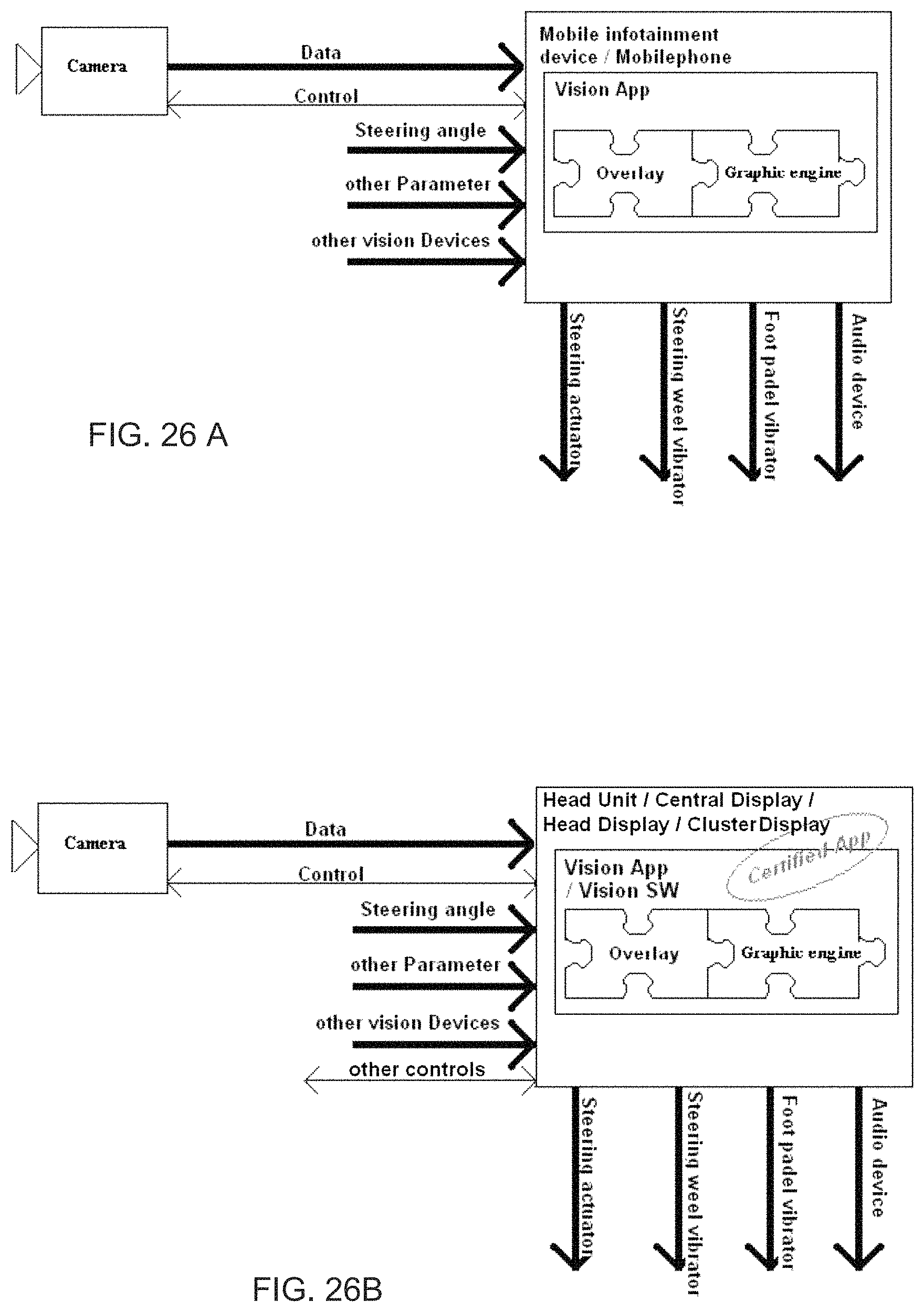
D00023
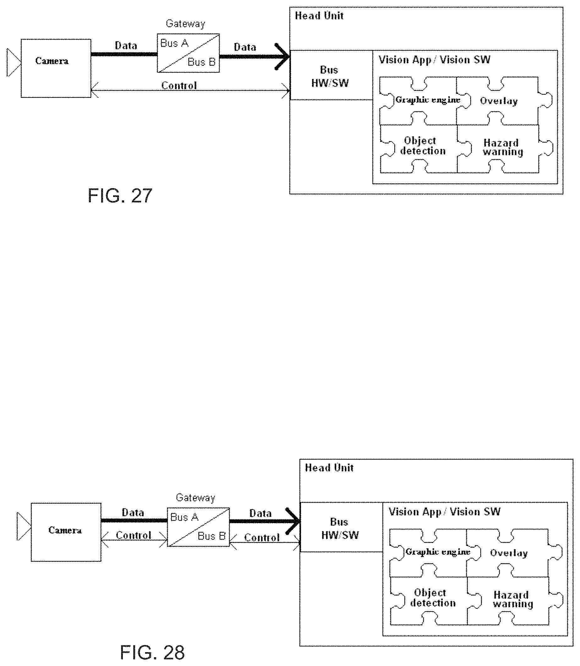
D00024
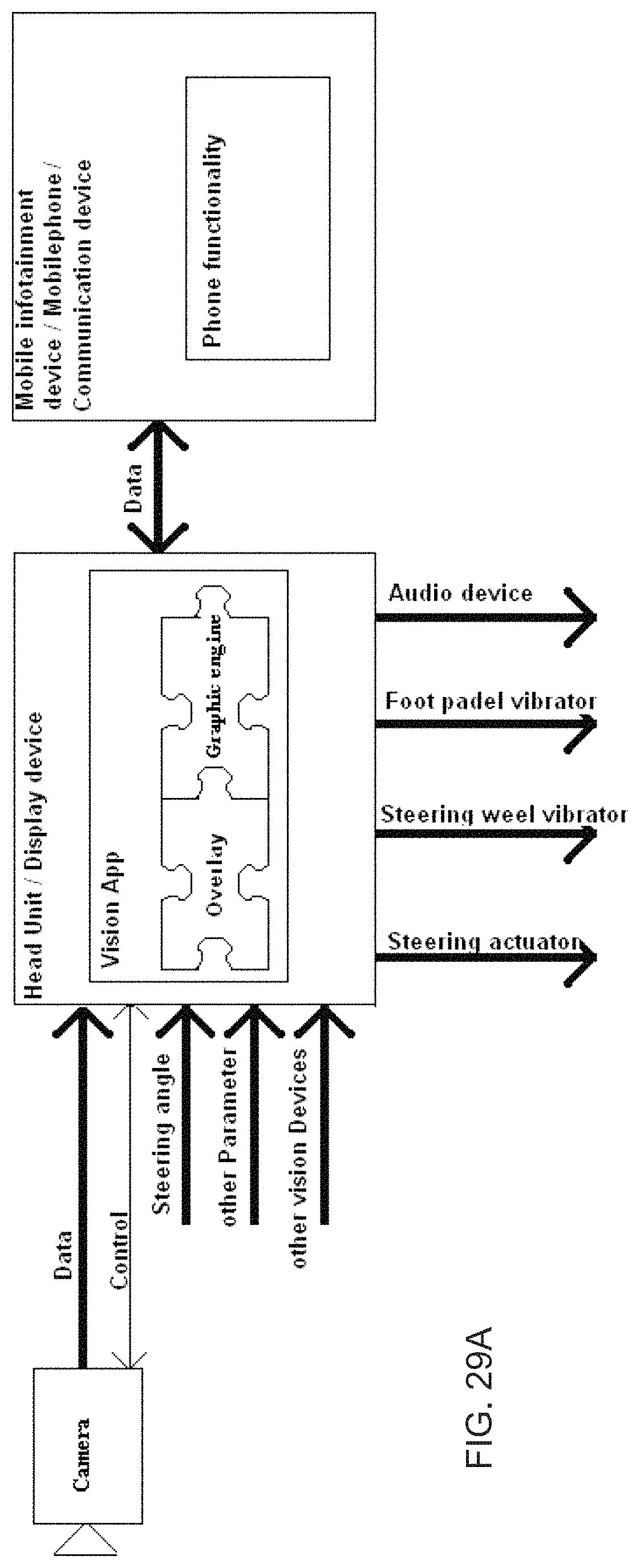
D00025
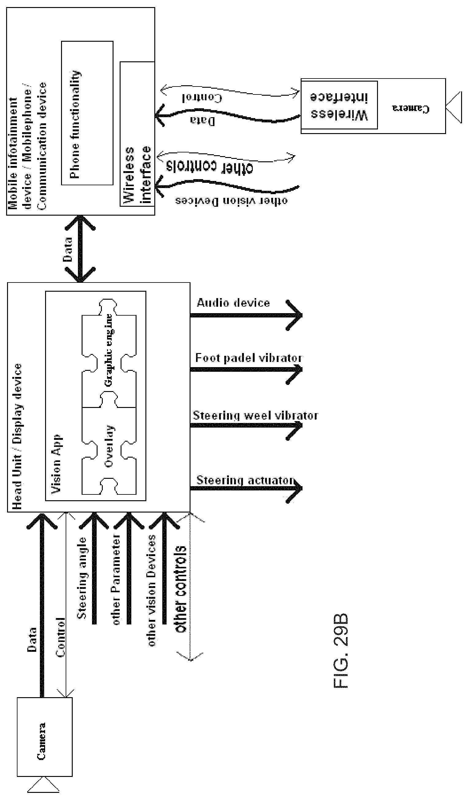
D00026
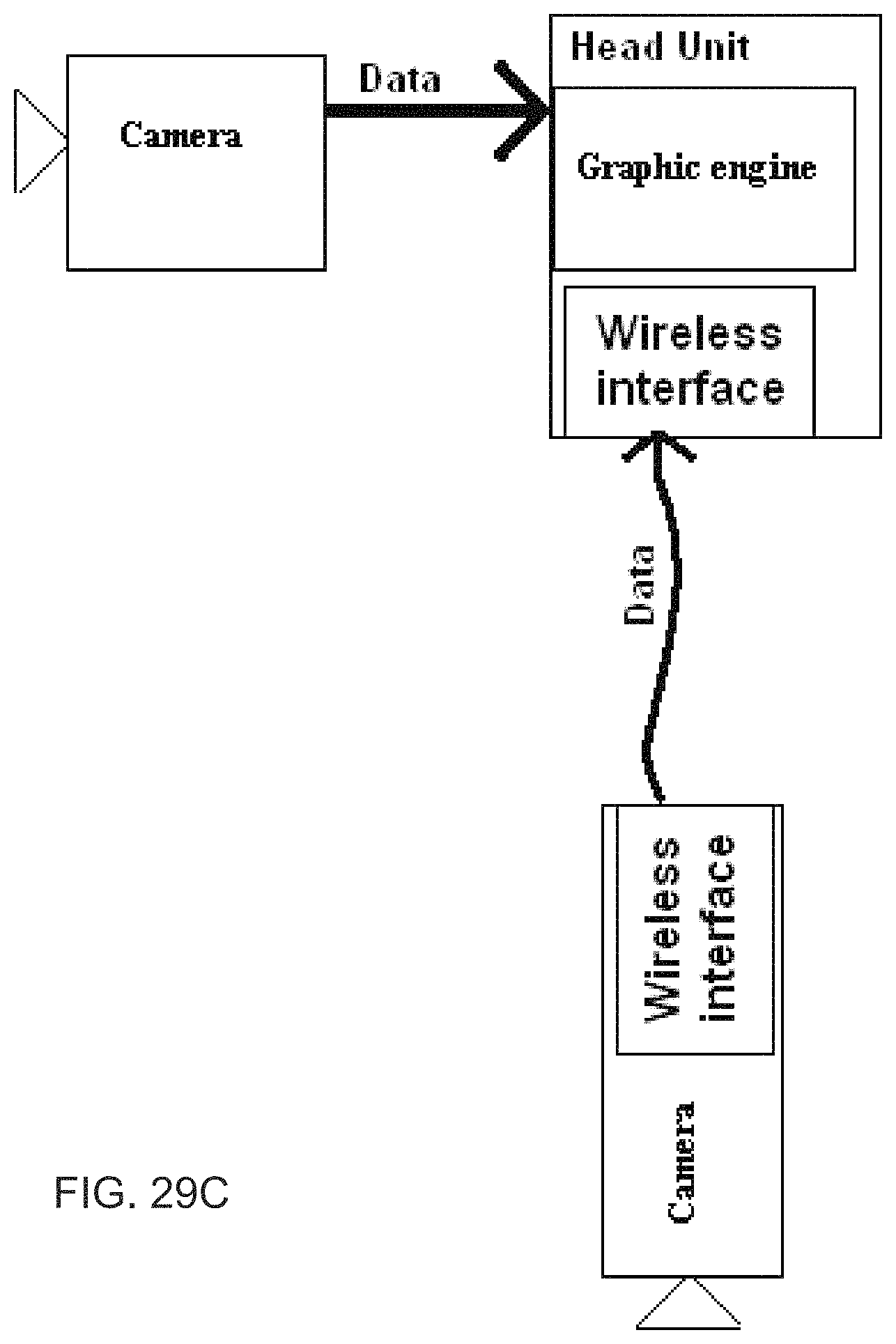
D00027
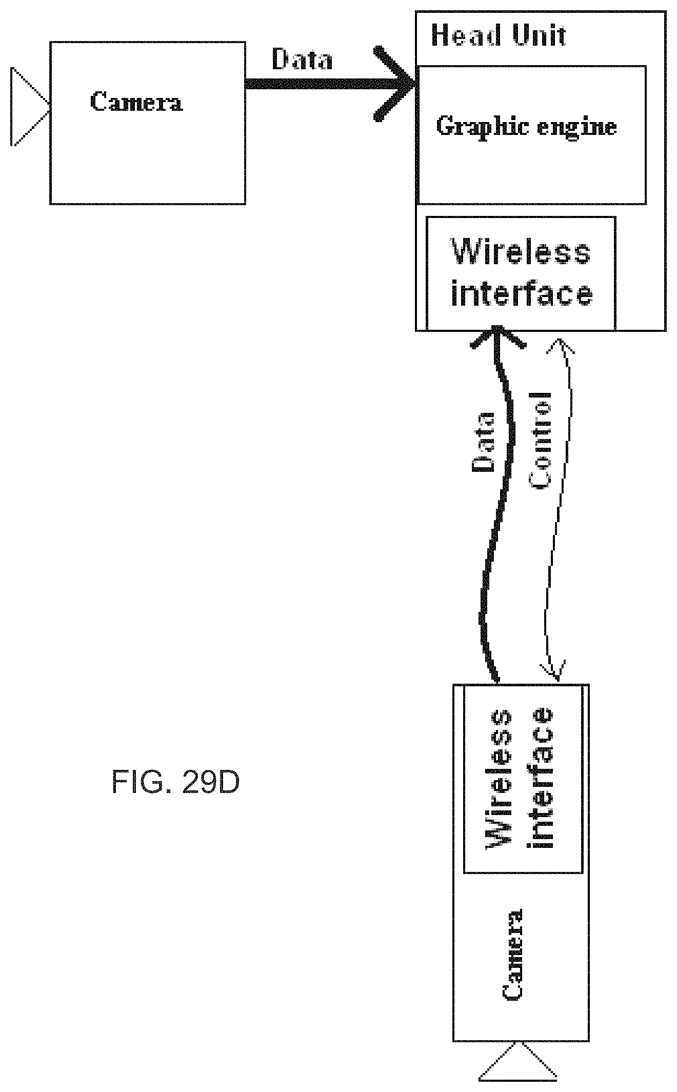
D00028
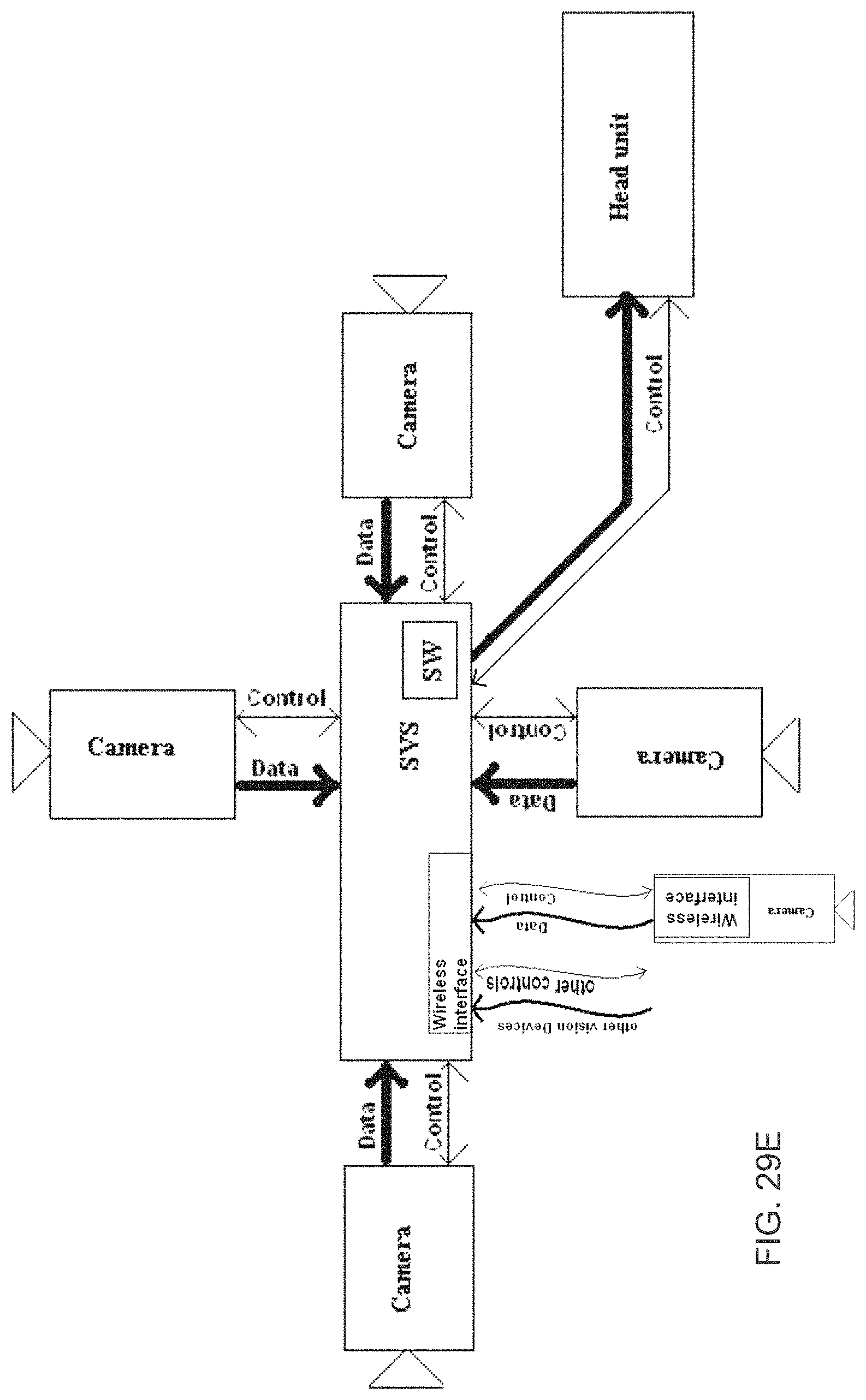
D00029

D00030
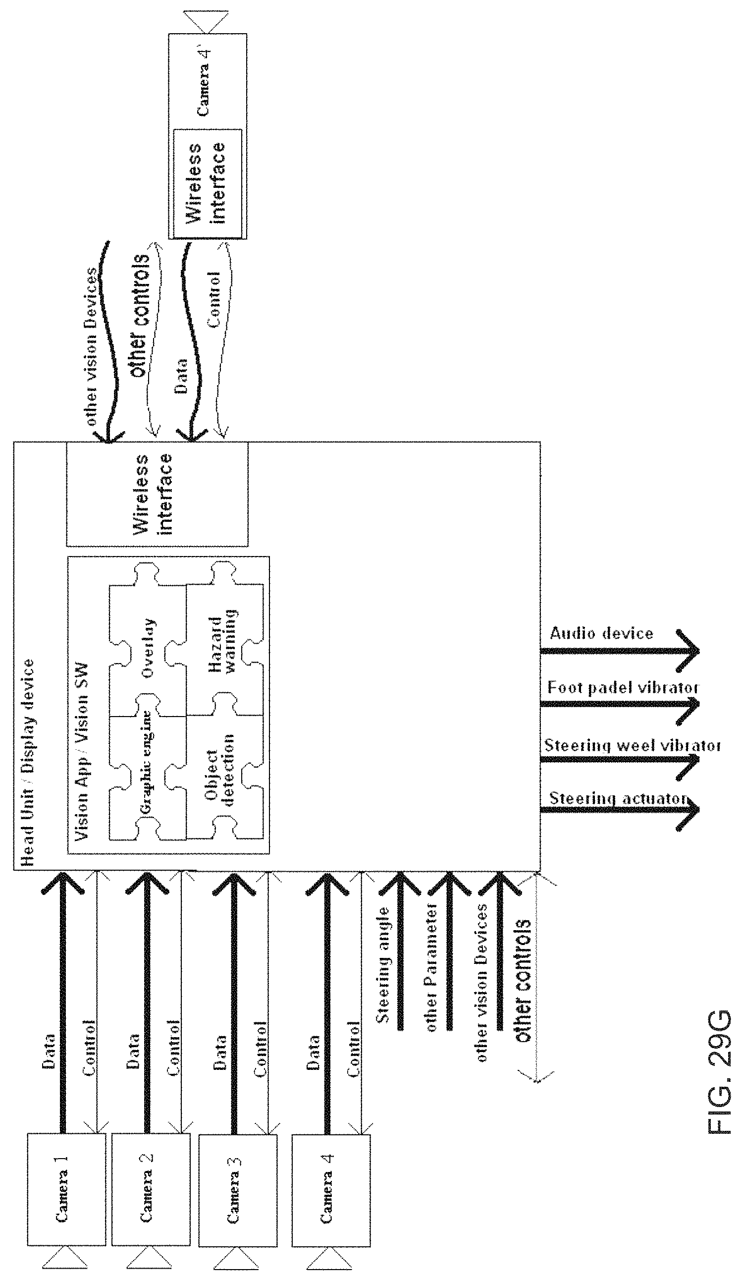
D00031
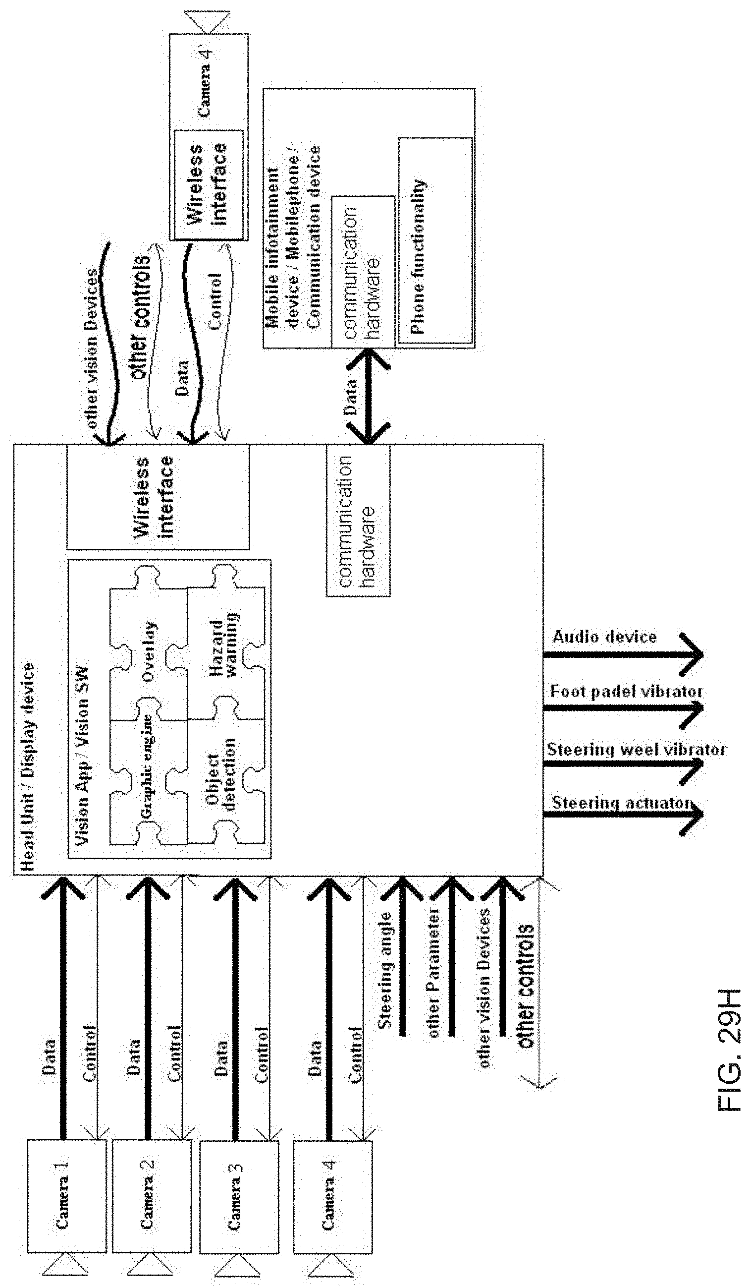
D00032

D00033
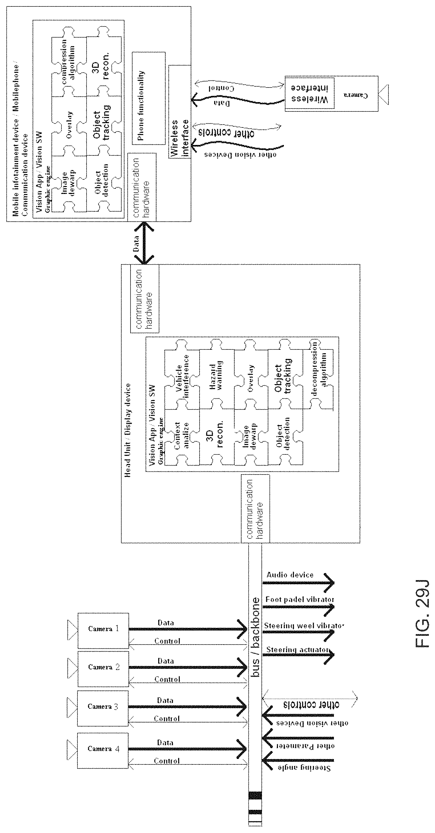
D00034
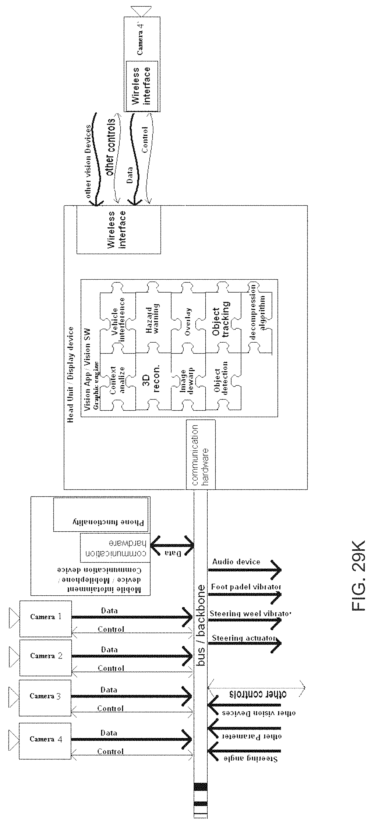
D00035
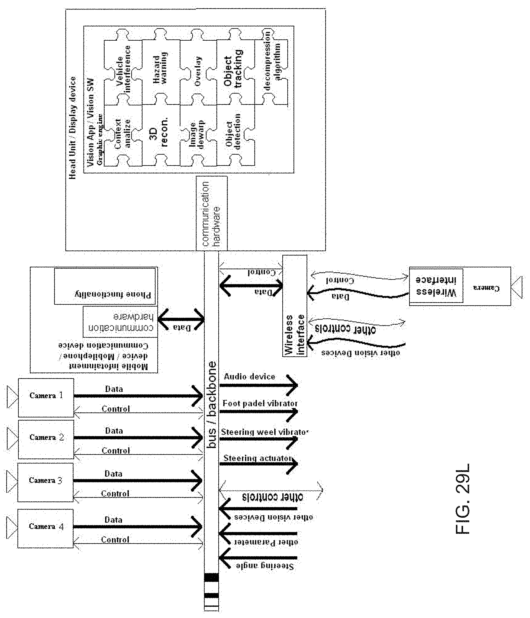
D00036
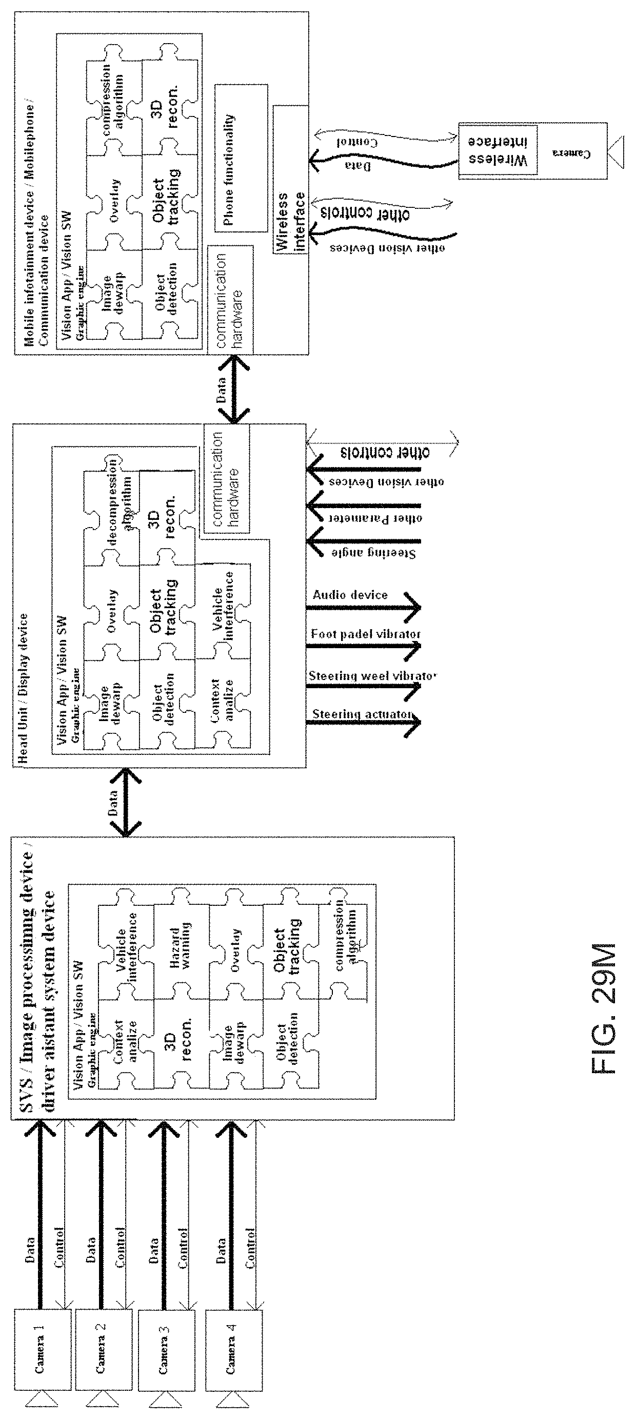
D00037

D00038
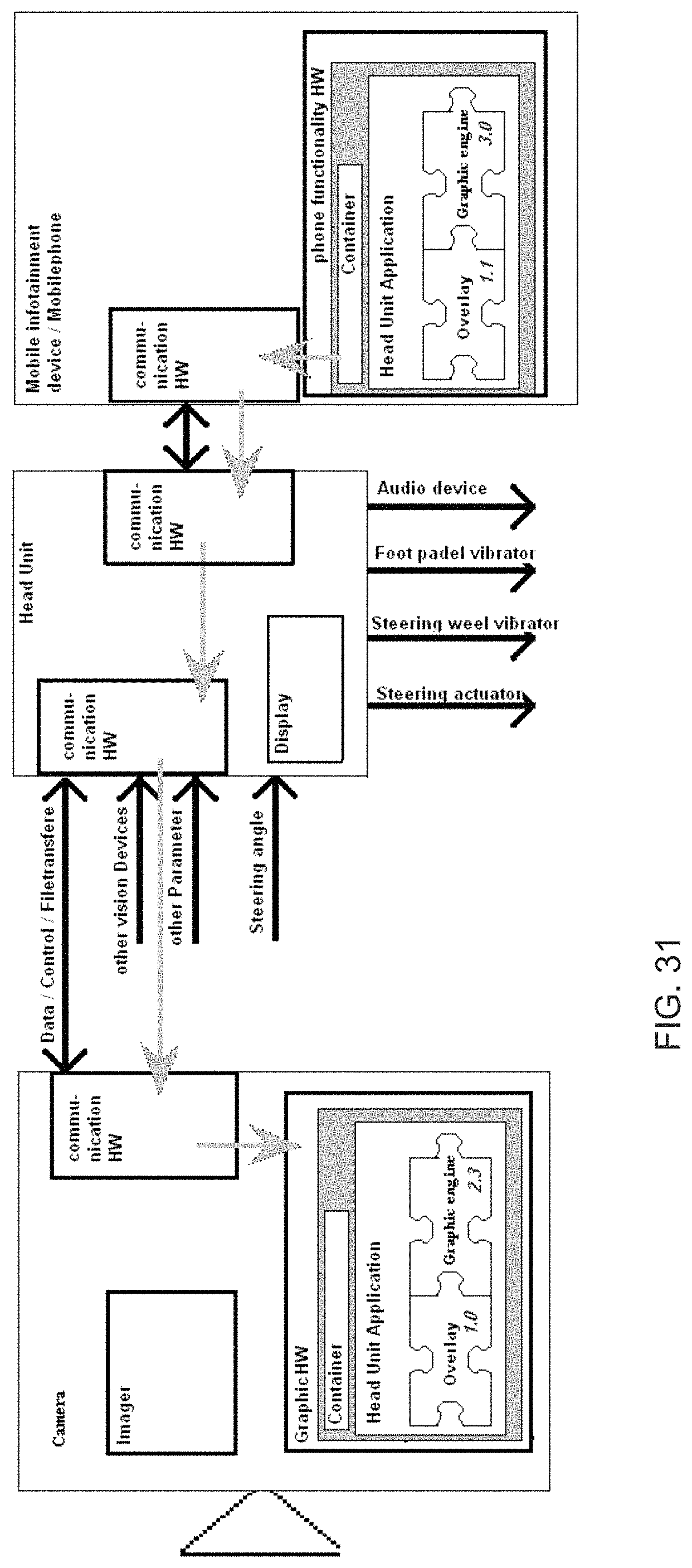
D00039
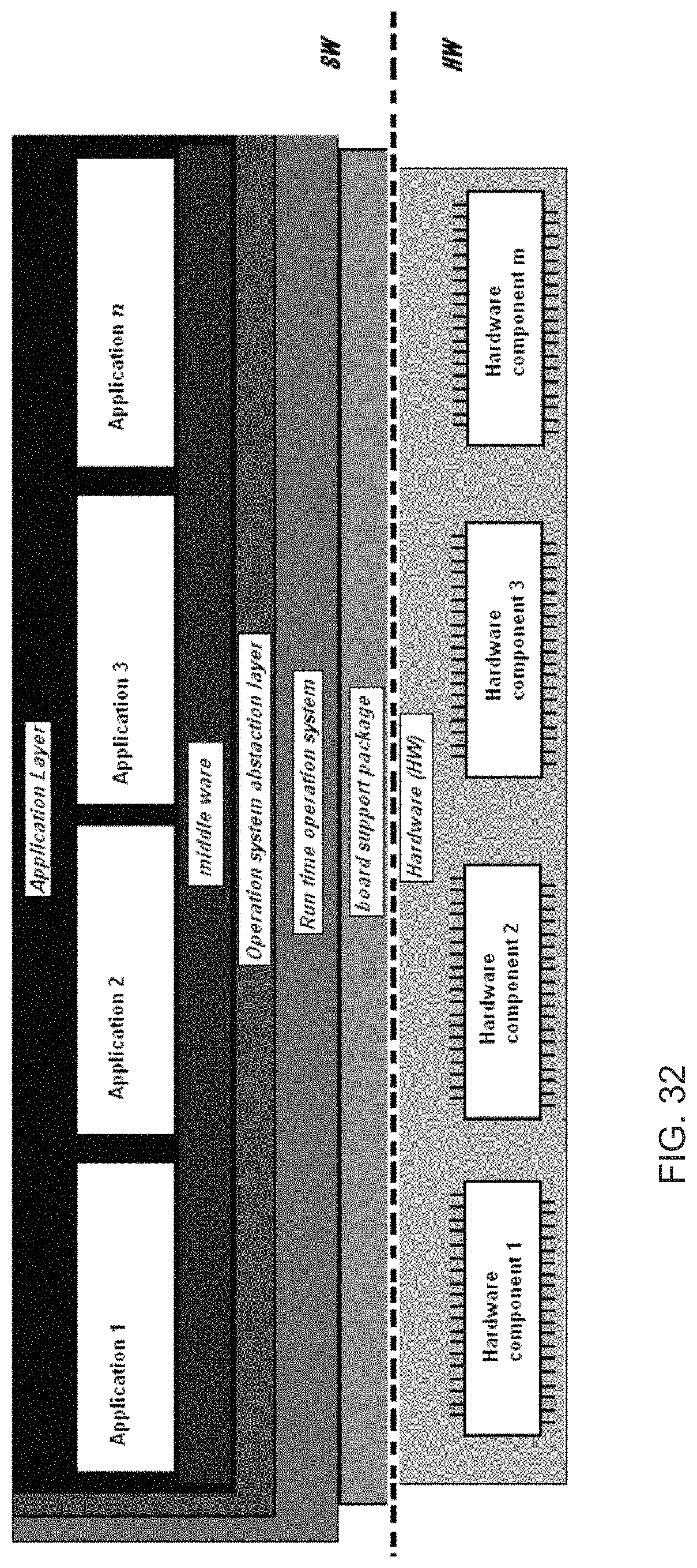
D00040
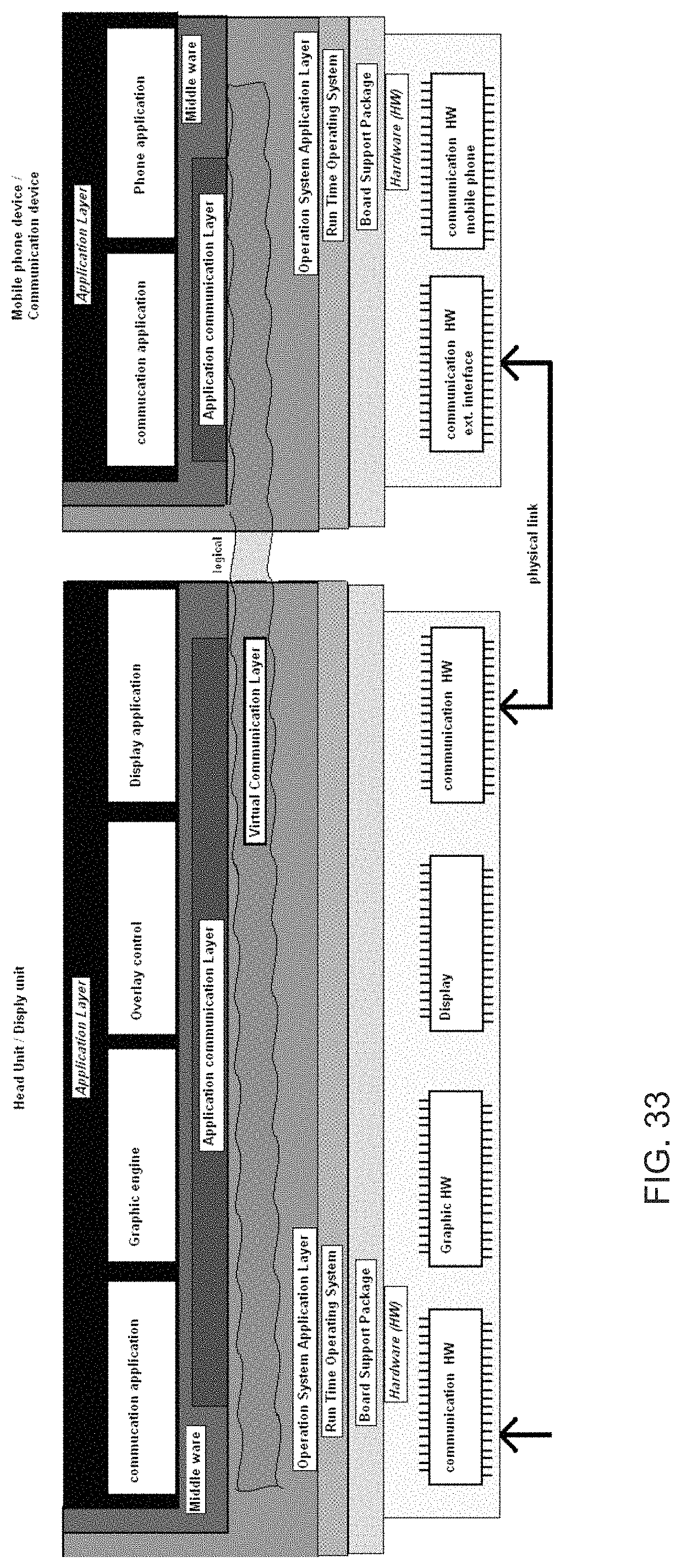
D00041

D00042
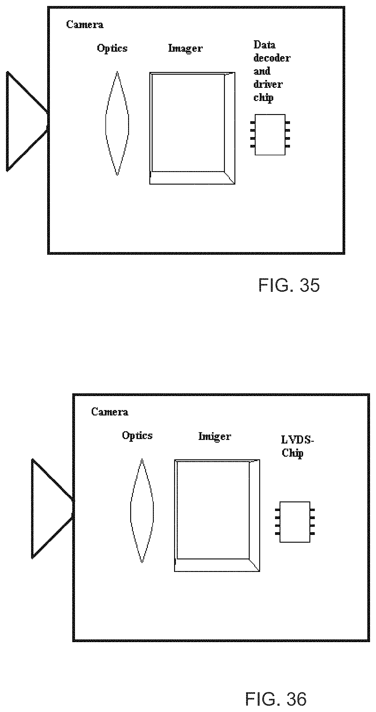
D00043
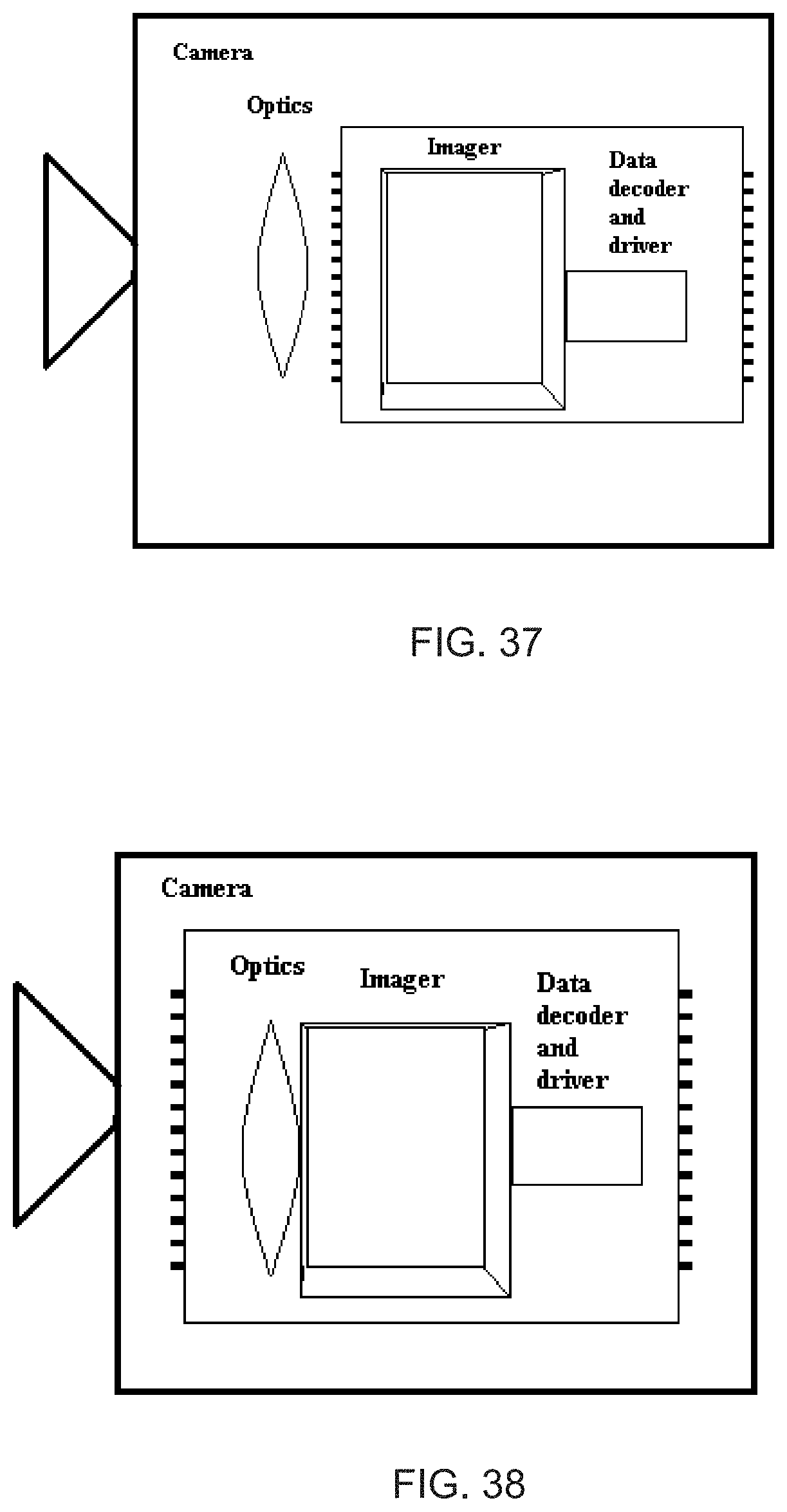
D00044
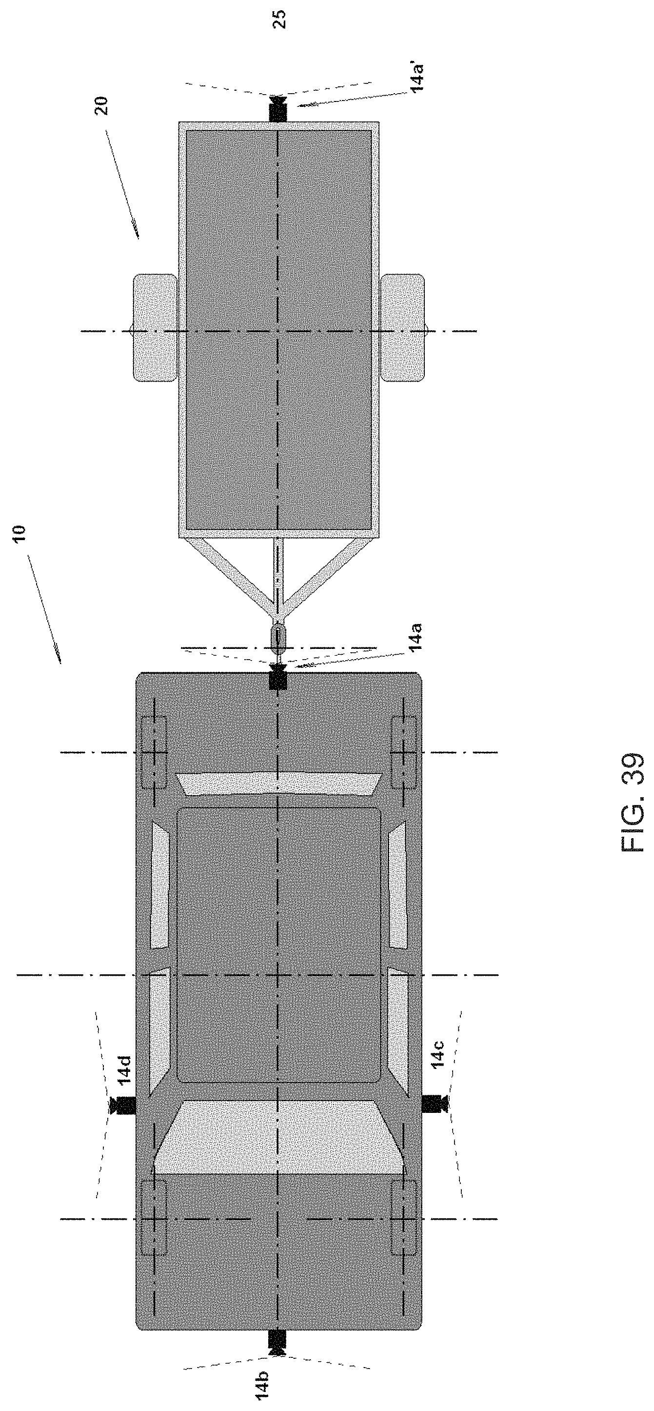
D00045
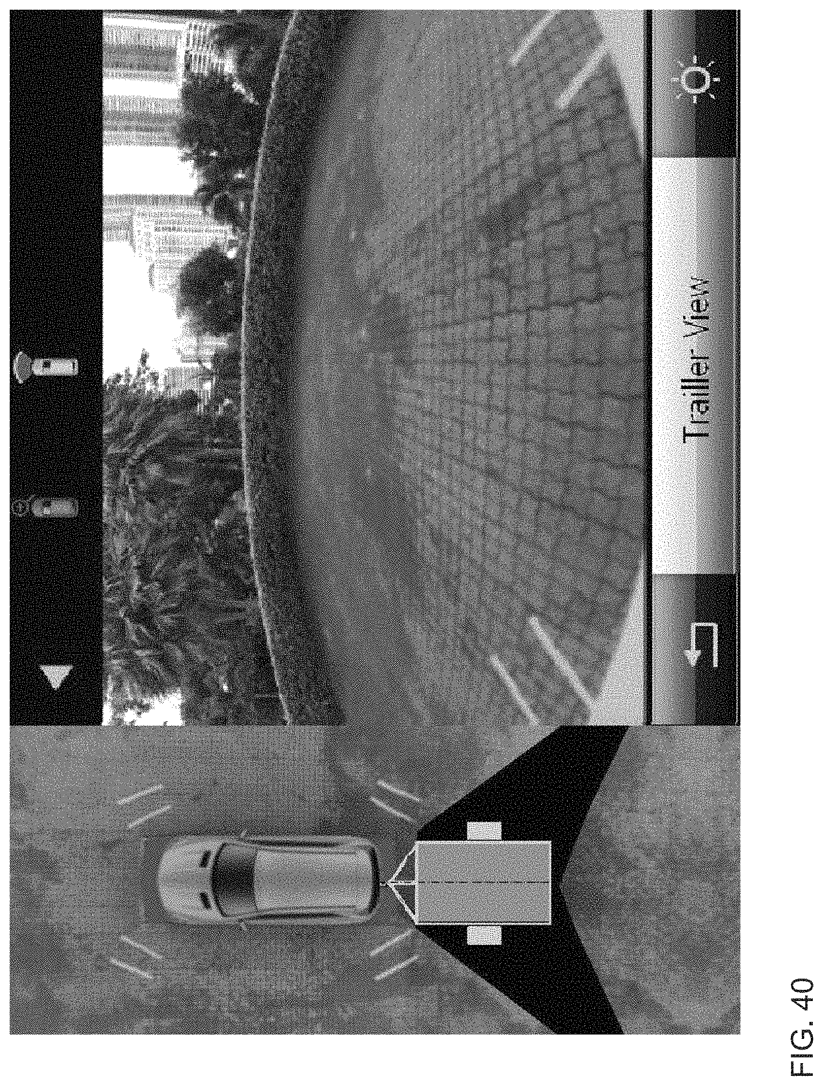
D00046
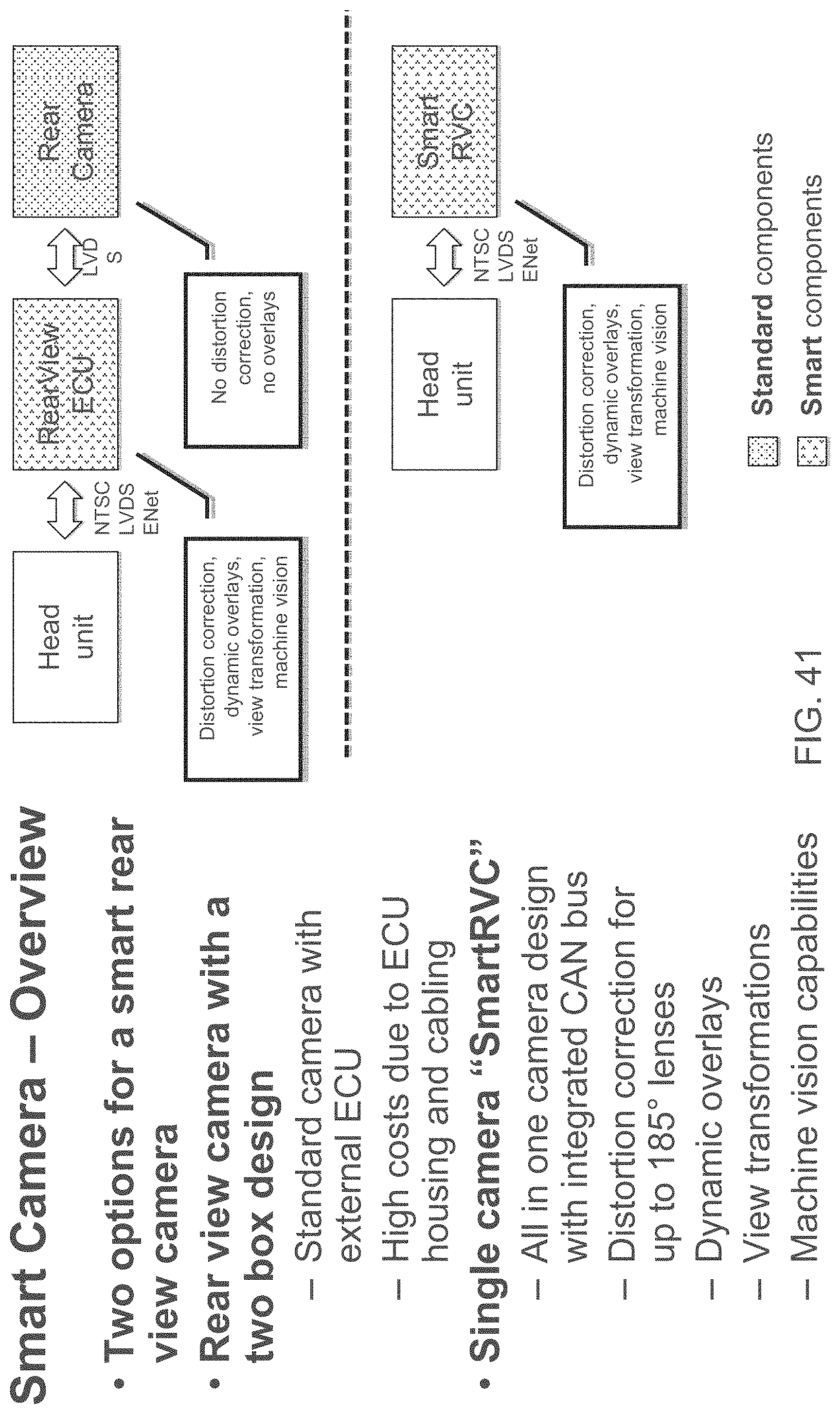
D00047
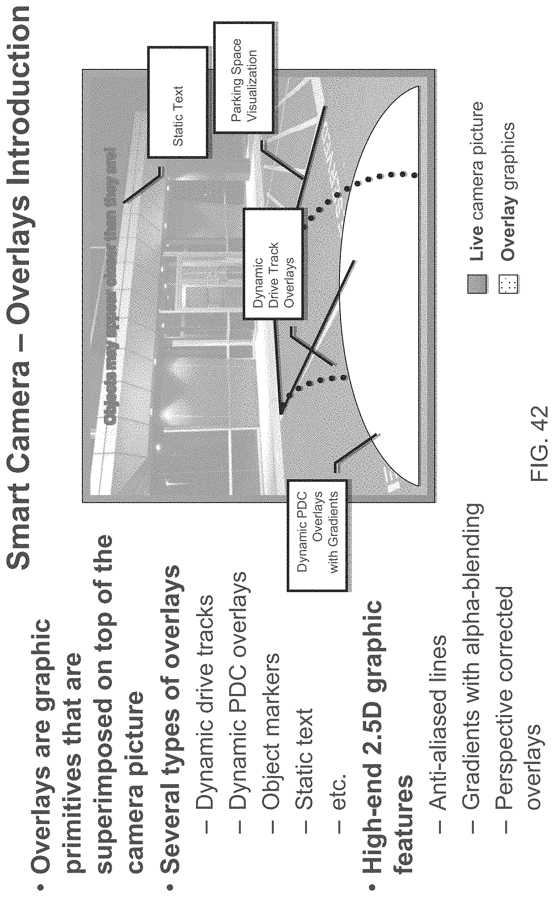
D00048
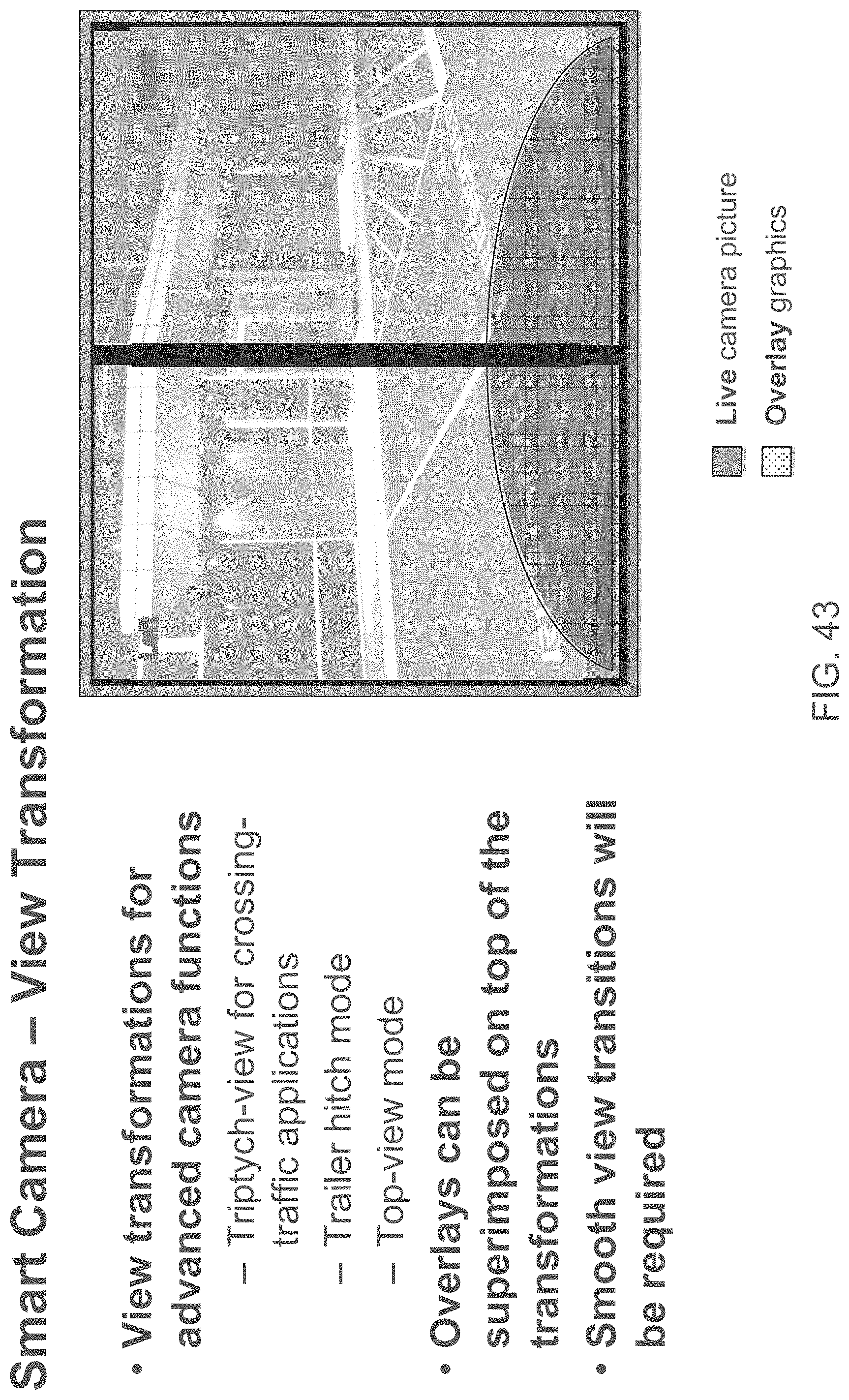
D00049
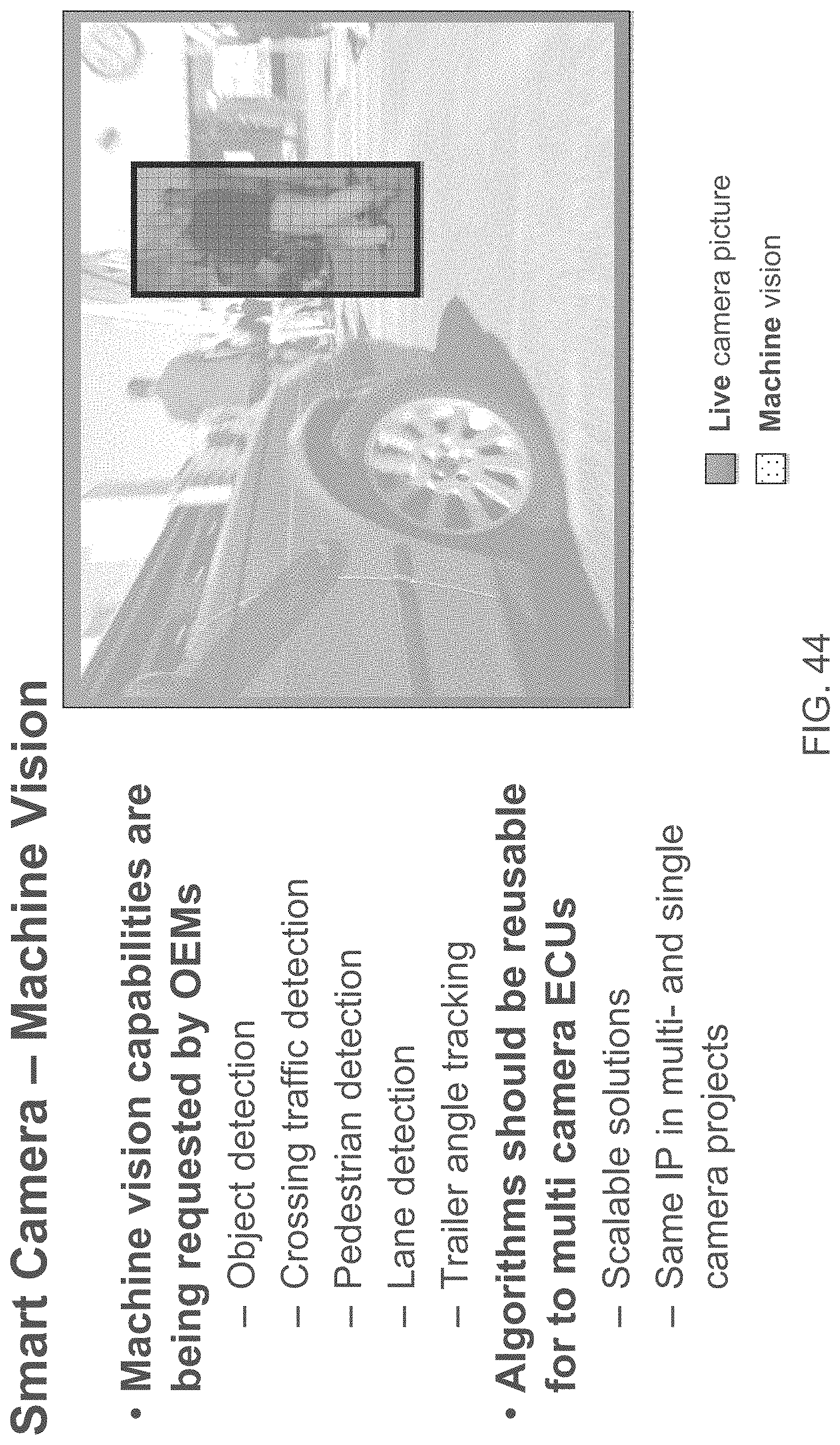
D00050

D00051

D00052
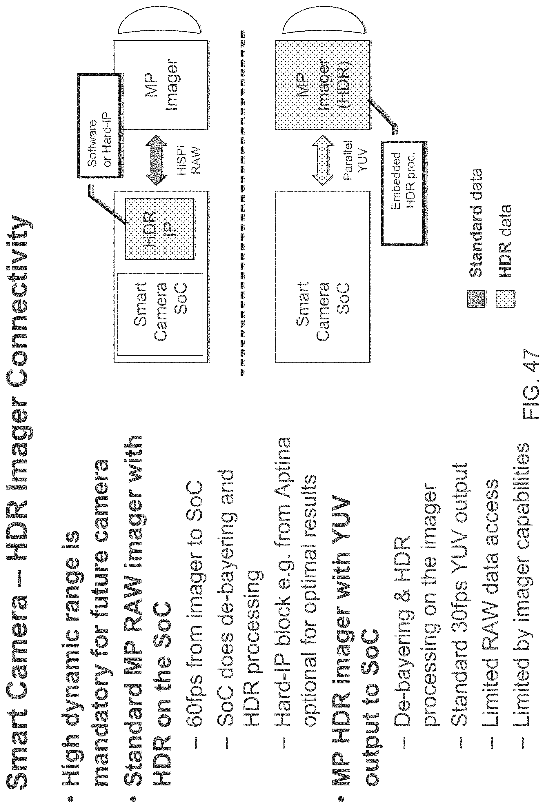
D00053
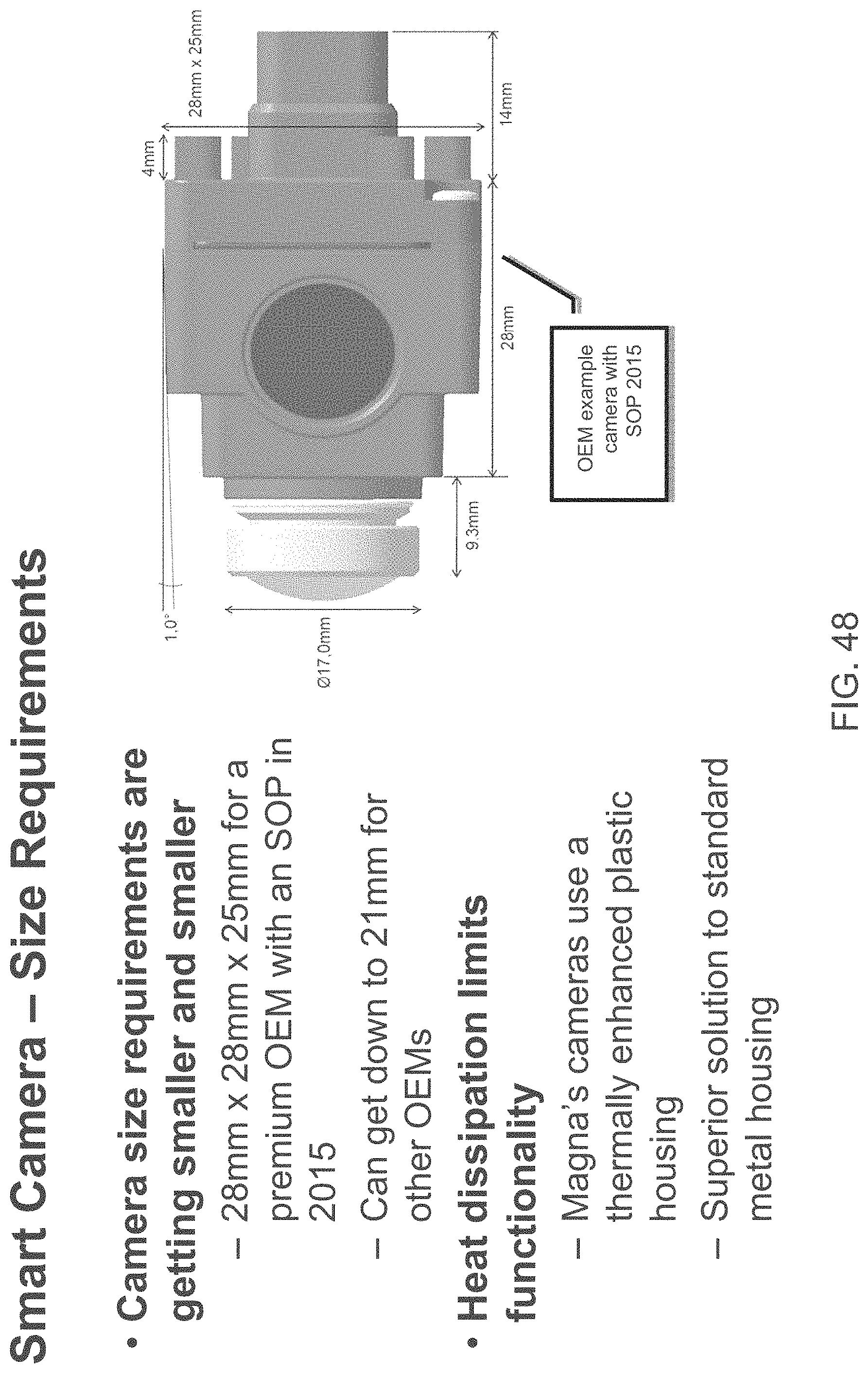
D00054

D00055
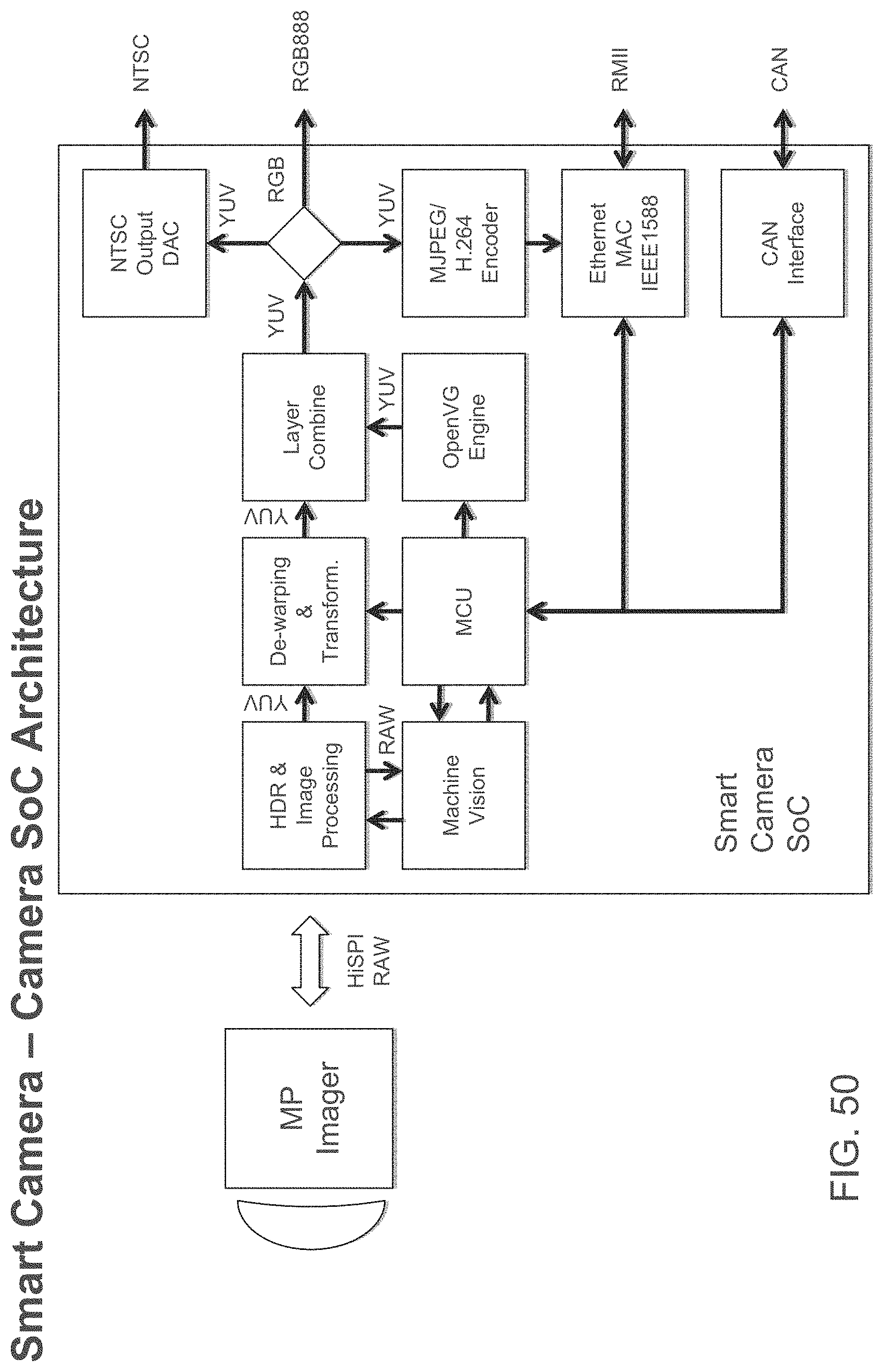
D00056
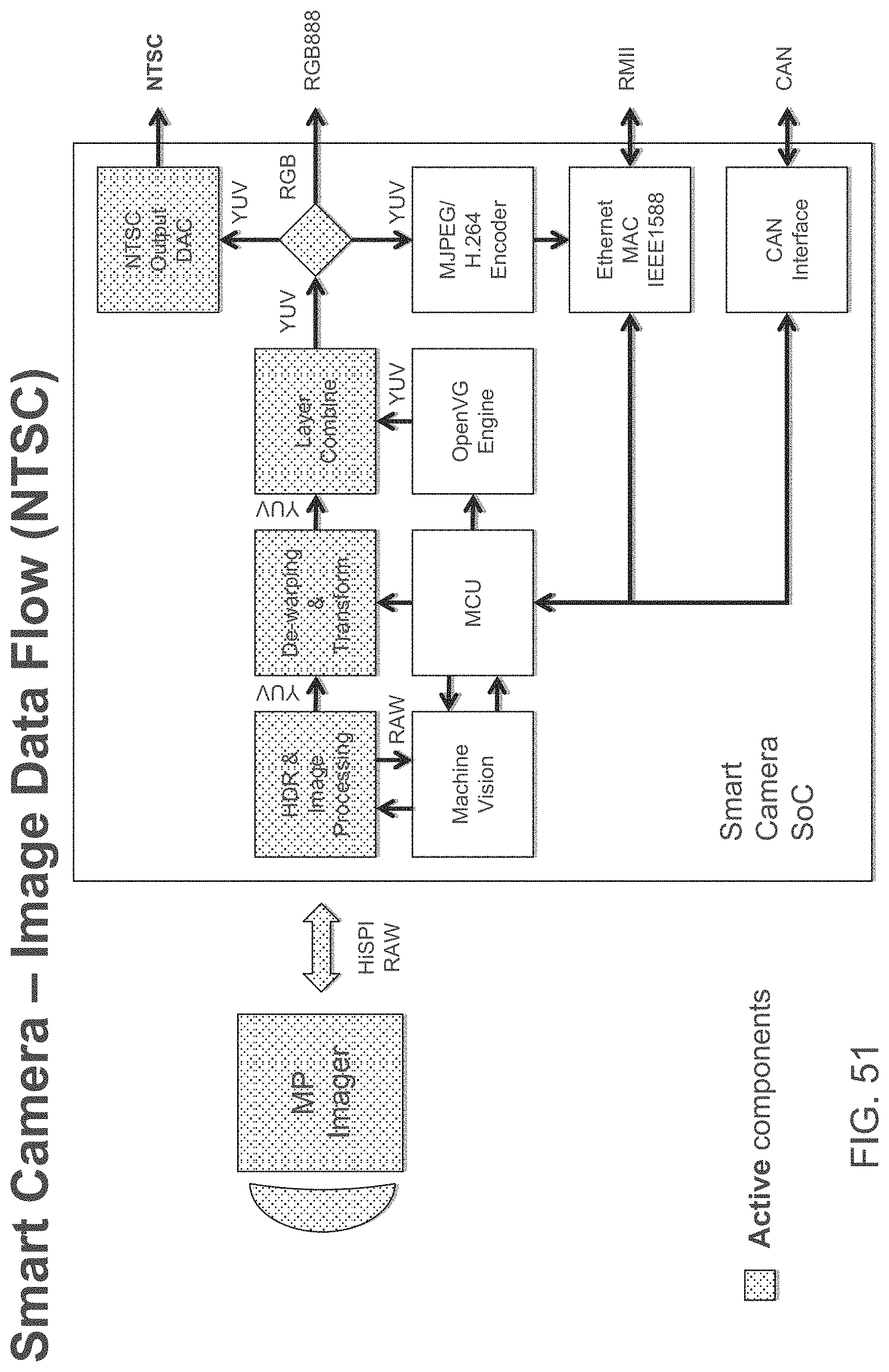
D00057
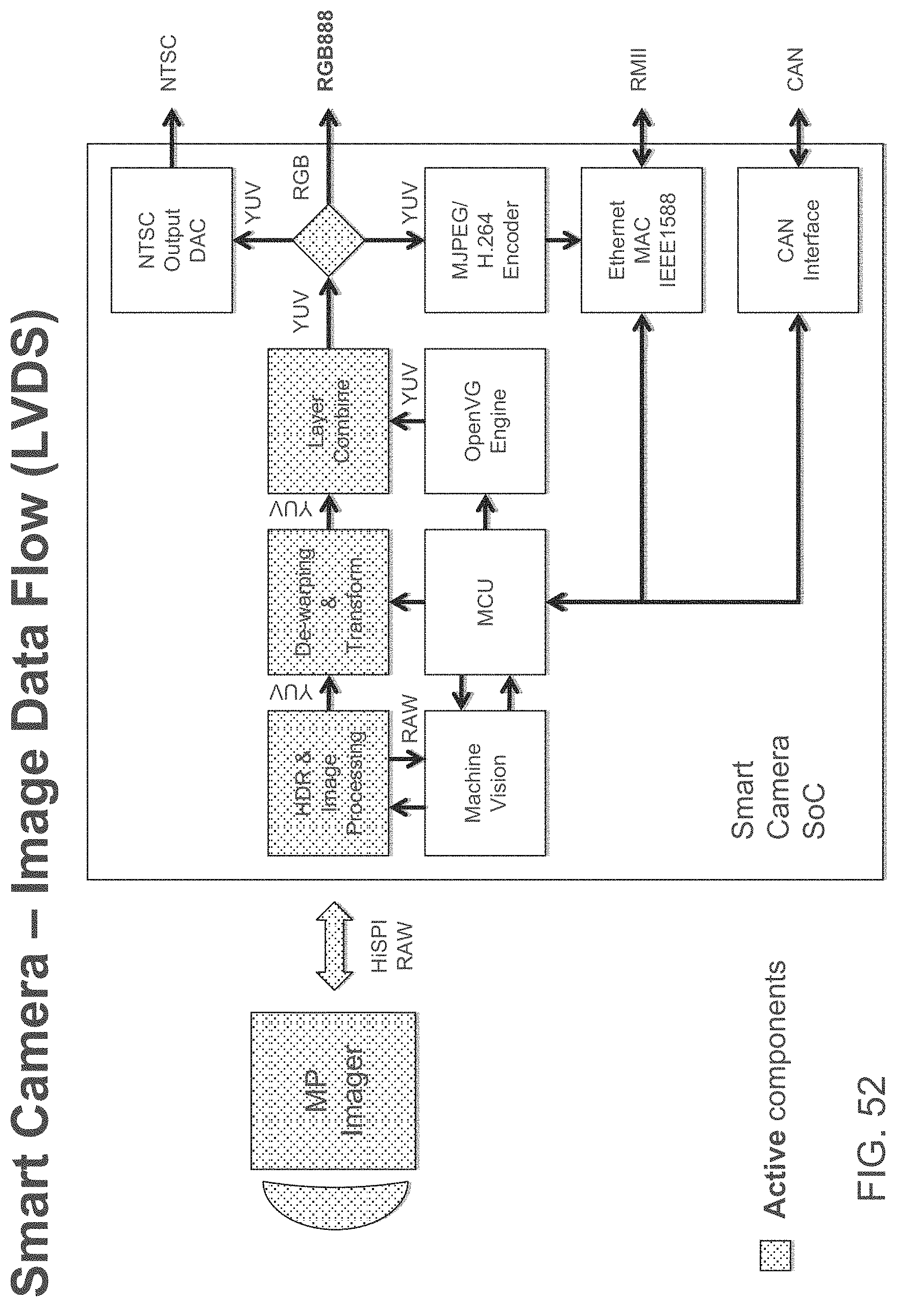
D00058
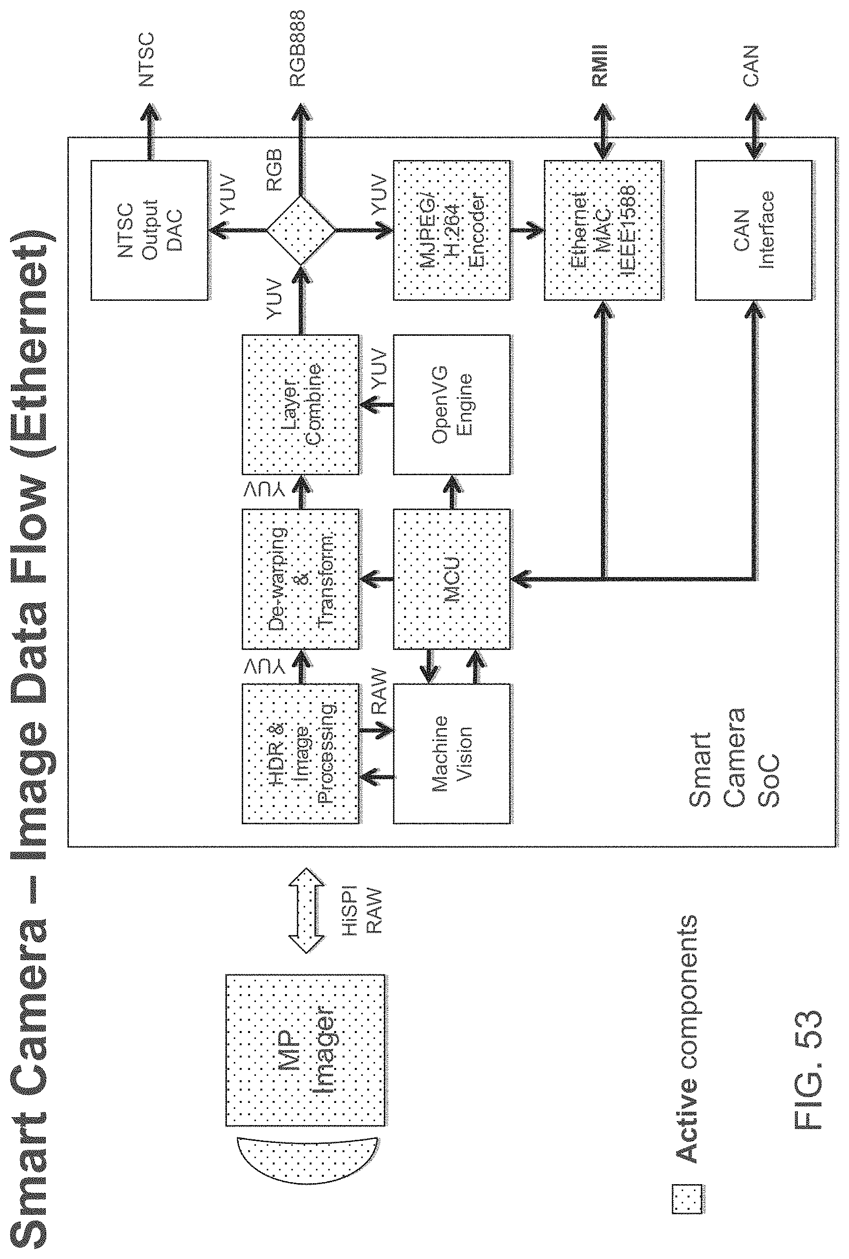
D00059
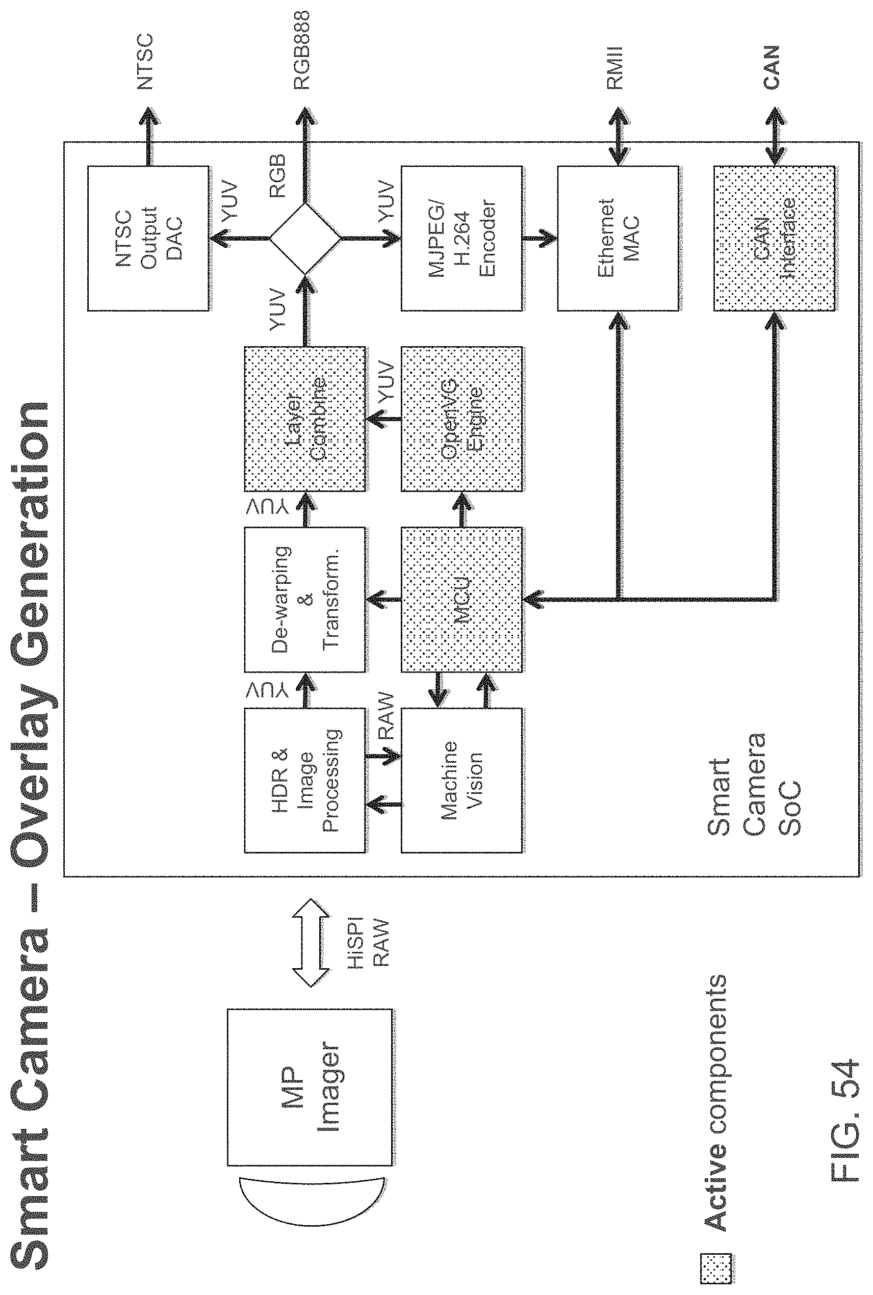
D00060
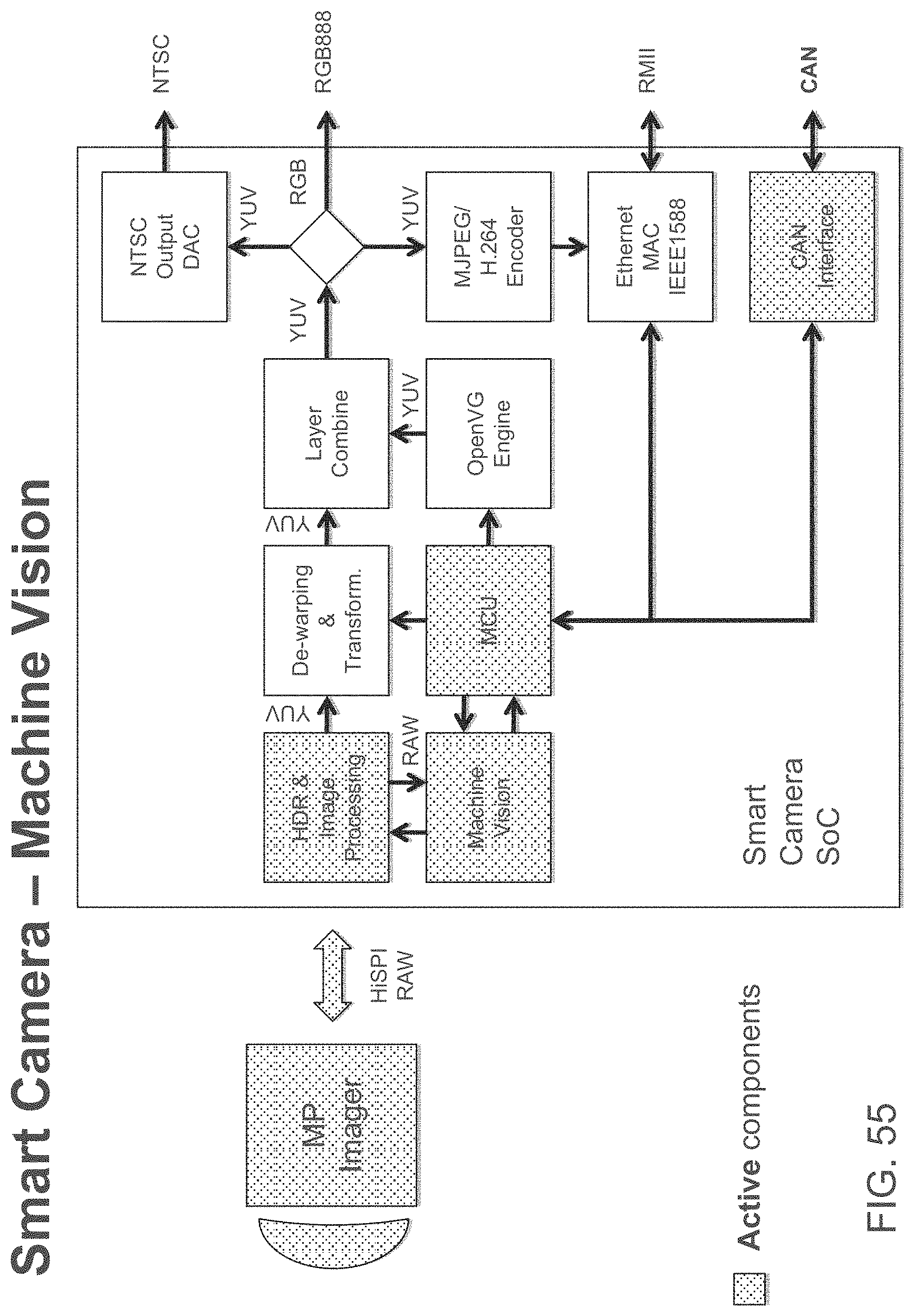
D00061

D00062
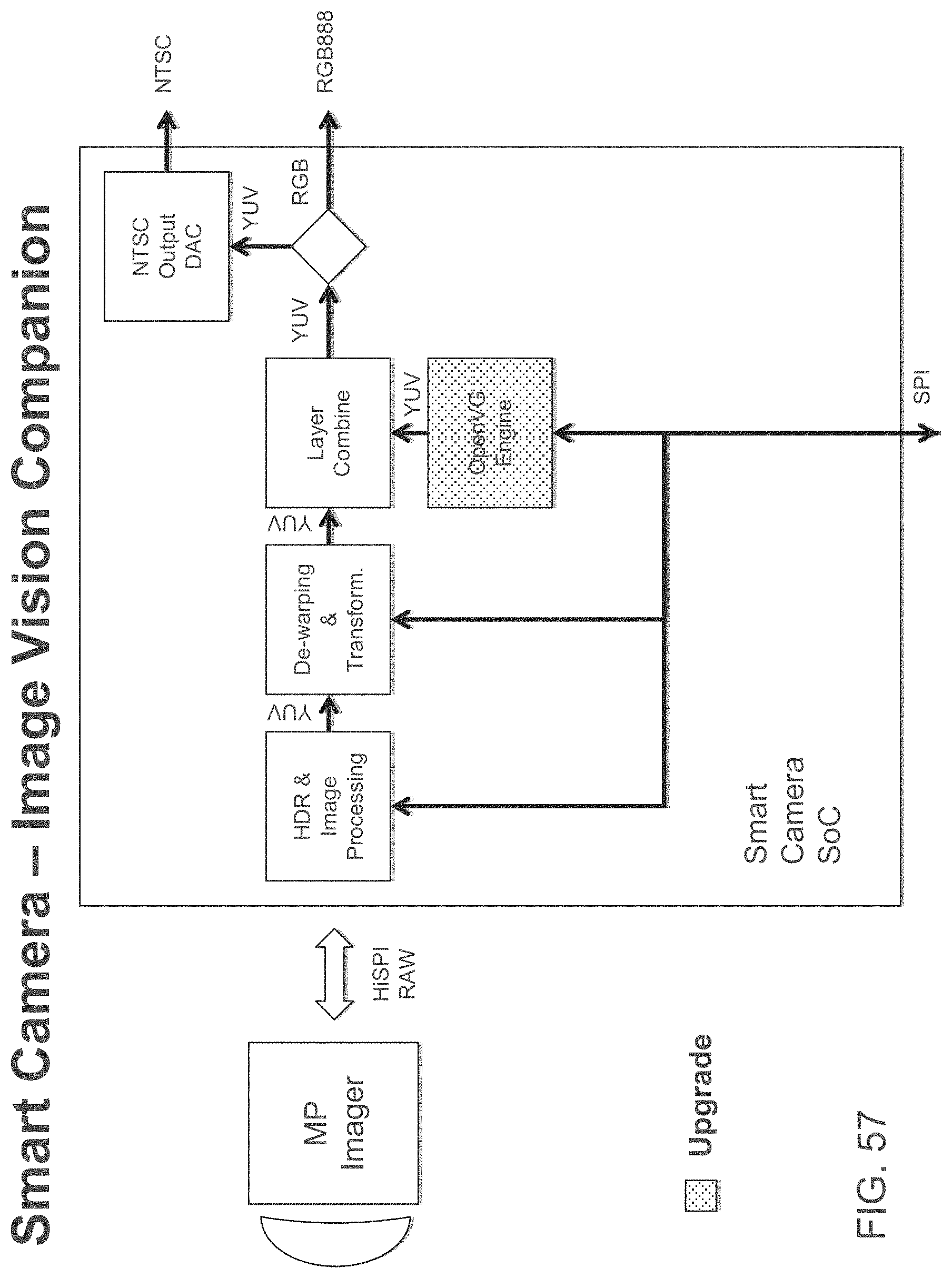
D00063

D00064

D00065
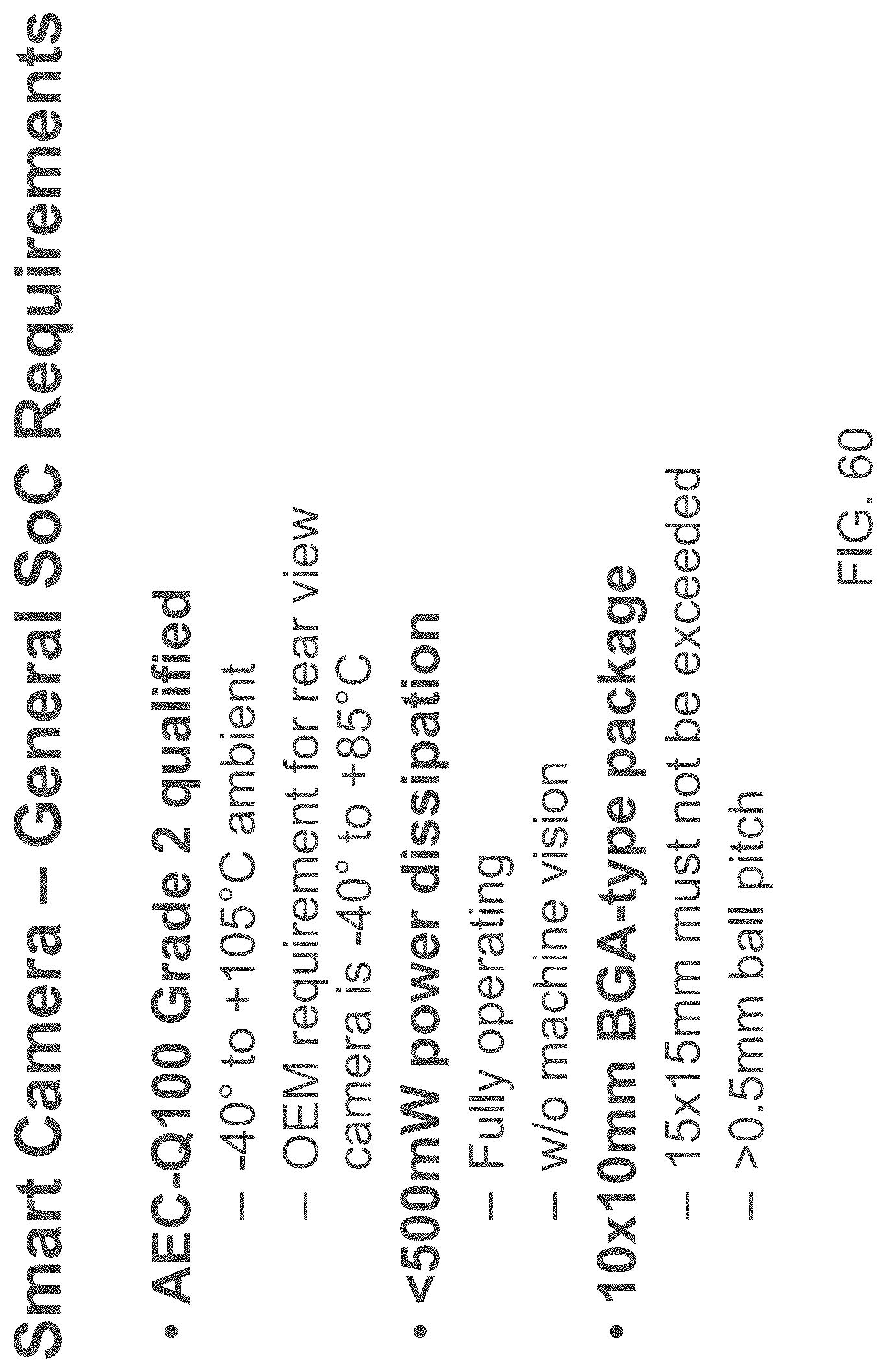
D00066

D00067
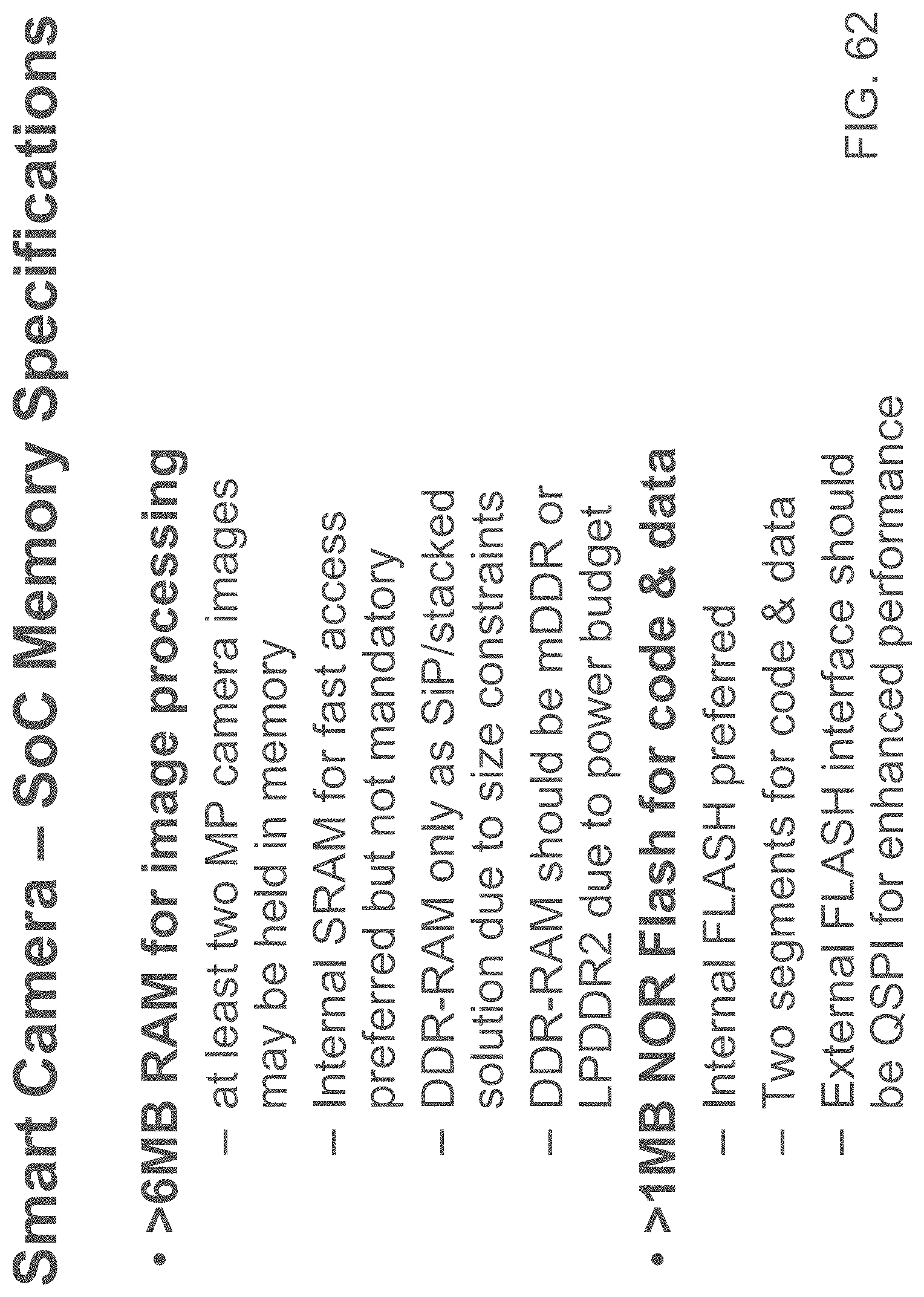
D00068
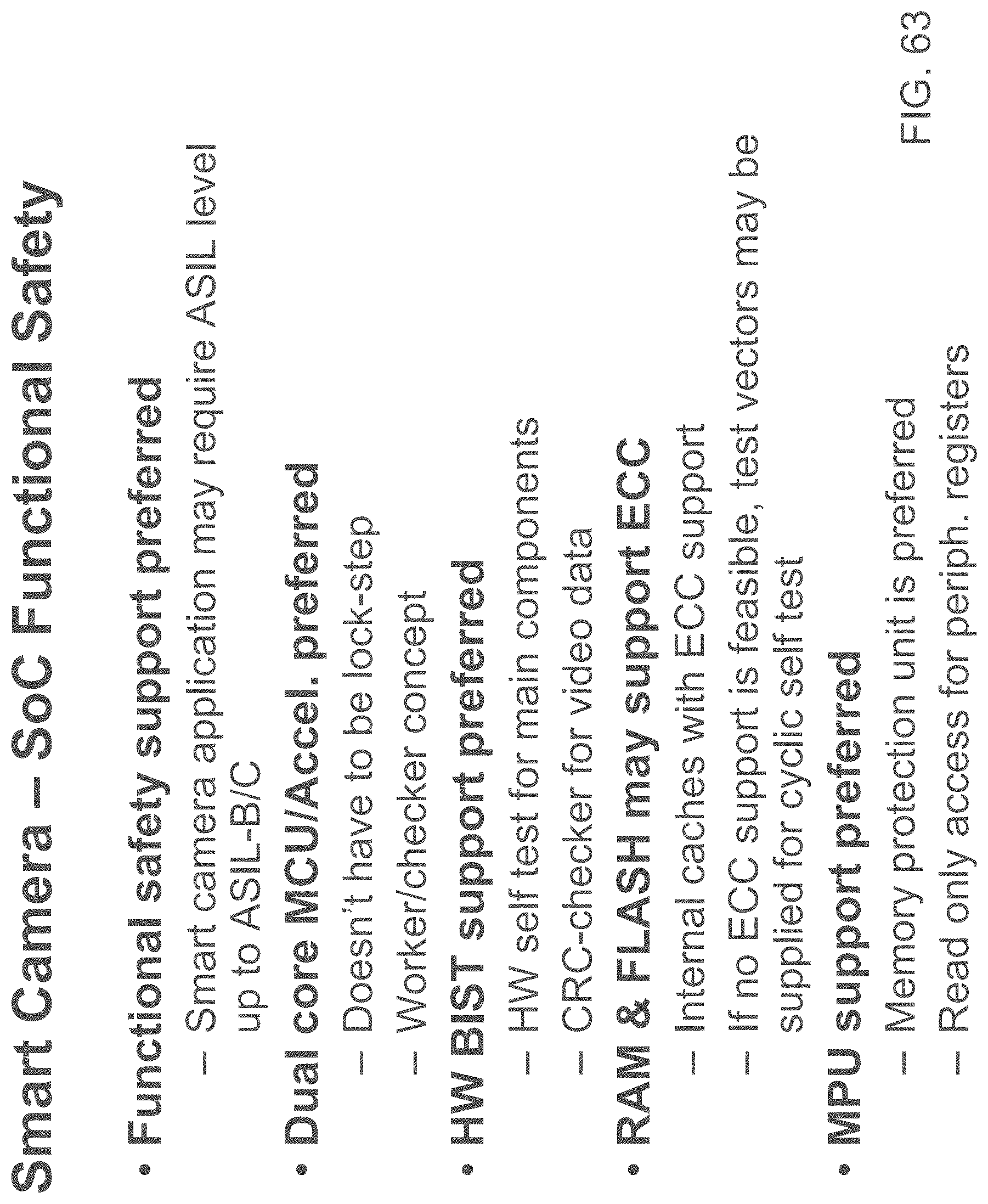
D00069
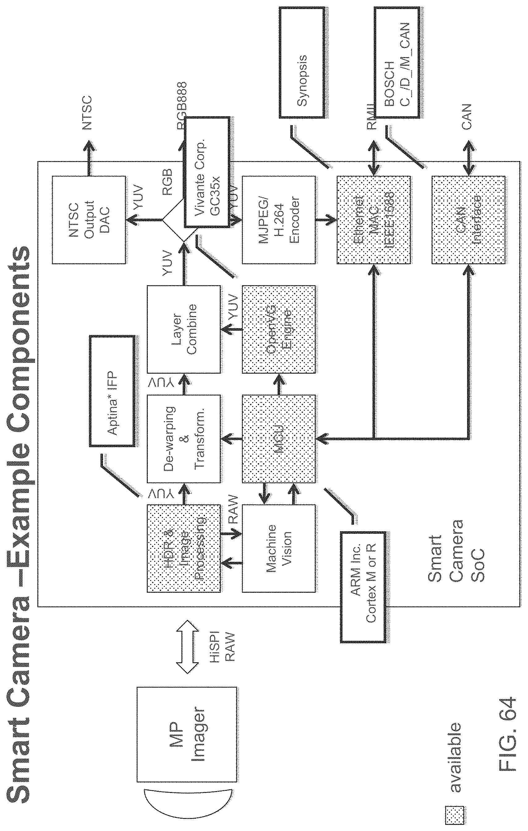
D00070

XML
uspto.report is an independent third-party trademark research tool that is not affiliated, endorsed, or sponsored by the United States Patent and Trademark Office (USPTO) or any other governmental organization. The information provided by uspto.report is based on publicly available data at the time of writing and is intended for informational purposes only.
While we strive to provide accurate and up-to-date information, we do not guarantee the accuracy, completeness, reliability, or suitability of the information displayed on this site. The use of this site is at your own risk. Any reliance you place on such information is therefore strictly at your own risk.
All official trademark data, including owner information, should be verified by visiting the official USPTO website at www.uspto.gov. This site is not intended to replace professional legal advice and should not be used as a substitute for consulting with a legal professional who is knowledgeable about trademark law.