Surgical instrument with resilient driving member and related methods of use
Garrison , et al.
U.S. patent number 10,639,095 [Application Number 15/972,166] was granted by the patent office on 2020-05-05 for surgical instrument with resilient driving member and related methods of use. This patent grant is currently assigned to COVIDIEN LP. The grantee listed for this patent is Covidien LP. Invention is credited to James D. Allen, IV, Kim V. Brandt, James S. Cunningham, David M. Garrison, Keir Hart, Daniel A. Joseph, Duane E. Kerr, Peter M. Mueller, Sean T. O'Neill, Jason T. Sanders, Robert M. Sharp, Jeffrey R. Unger.


View All Diagrams
| United States Patent | 10,639,095 |
| Garrison , et al. | May 5, 2020 |
Surgical instrument with resilient driving member and related methods of use
Abstract
A forceps is provided and includes a housing having a shaft. An end effector assembly operatively connects to a distal end of the shaft and includes a pair of first and second jaw members. One or both of the first and second jaw members is movable relative to the other jaw member from a clamping position to an open position. A resilient member operably couples to at least one of the first and second jaw members. The resilient member is configured to bias the first and second jaw members in the clamping position and provide a closure force on tissue disposed therebetween.
| Inventors: | Garrison; David M. (Longmont, CO), Allen, IV; James D. (Broomfield, CO), Unger; Jeffrey R. (Longmont, CO), Kerr; Duane E. (Loveland, CO), O'Neill; Sean T. (Los Gatos, CA), Mueller; Peter M. (Frederick, CO), Brandt; Kim V. (Loveland, CO), Cunningham; James S. (Boulder, CO), Hart; Keir (Lafayette, CO), Joseph; Daniel A. (Golden, CO), Sanders; Jason T. (Boulder, CO), Sharp; Robert M. (Boulder, CO) | ||||||||||
|---|---|---|---|---|---|---|---|---|---|---|---|
| Applicant: |
|
||||||||||
| Assignee: | COVIDIEN LP (Mansfield,
MA) |
||||||||||
| Family ID: | 47631317 | ||||||||||
| Appl. No.: | 15/972,166 | ||||||||||
| Filed: | May 6, 2018 |
Prior Publication Data
| Document Identifier | Publication Date | |
|---|---|---|
| US 20180250068 A1 | Sep 6, 2018 | |
Related U.S. Patent Documents
| Application Number | Filing Date | Patent Number | Issue Date | ||
|---|---|---|---|---|---|
| 15356786 | Nov 21, 2016 | 9974605 | |||
| 14635124 | Nov 29, 2016 | 9504514 | |||
| 13357979 | Mar 3, 2015 | 8968360 | |||
| Current U.S. Class: | 1/1 |
| Current CPC Class: | A61B 17/29 (20130101); A61B 18/1206 (20130101); A61B 18/12 (20130101); A61B 18/1445 (20130101); A61B 2017/2902 (20130101); A61B 2017/2905 (20130101); A61B 2017/2936 (20130101); A61B 2018/0063 (20130101); A61B 2090/034 (20160201) |
| Current International Class: | A61B 5/00 (20060101); A61B 17/29 (20060101); A61B 18/14 (20060101); A61B 18/12 (20060101); A61B 90/00 (20160101); A61B 18/00 (20060101) |
References Cited [Referenced By]
U.S. Patent Documents
| D249549 | September 1978 | Pike |
| D263020 | February 1982 | Rau, III |
| D295893 | May 1988 | Sharkany et al. |
| D295894 | May 1988 | Sharkany et al. |
| D298353 | November 1988 | Manno |
| D299413 | January 1989 | DeCarolis |
| 5269780 | December 1993 | Roos |
| D343453 | January 1994 | Noda |
| D348930 | July 1994 | Olson |
| 5330471 | July 1994 | Eggers |
| D349341 | August 1994 | Lichtman et al. |
| D354564 | January 1995 | Medema |
| 5391166 | February 1995 | Eggers |
| 5403312 | April 1995 | Yates et al. |
| D358887 | May 1995 | Feinberg |
| 5496347 | March 1996 | Hashiguchi et al. |
| 5507297 | April 1996 | Slater et al. |
| 5575799 | November 1996 | Bolanos et al. |
| 5599350 | February 1997 | Schulze et al. |
| 5618307 | April 1997 | Donlon et al. |
| 5624452 | April 1997 | Yates |
| 5626607 | May 1997 | Malecki et al. |
| D384413 | September 1997 | Zlock et al. |
| 5688270 | November 1997 | Yates et al. |
| 5690652 | November 1997 | Wurster et al. |
| 5693051 | December 1997 | Schulze et al. |
| 5709680 | January 1998 | Yates et al. |
| 5716366 | February 1998 | Yates |
| 5735848 | April 1998 | Yates et al. |
| 5766170 | June 1998 | Eggers |
| 5769849 | June 1998 | Eggers |
| H001745 | August 1998 | Paraschac |
| 5797941 | August 1998 | Schulze et al. |
| 5807393 | September 1998 | Williamson, IV et al. |
| 5810811 | September 1998 | Yates et al. |
| 5833690 | November 1998 | Yates et al. |
| D402028 | December 1998 | Grimm et al. |
| 5876401 | March 1999 | Schulze et al. |
| D408018 | April 1999 | McNaughton |
| D416089 | November 1999 | Barton et al. |
| 6024741 | February 2000 | Williamson, IV et al. |
| D424694 | May 2000 | Tetzlaff et al. |
| D425201 | May 2000 | Tetzlaff et al. |
| 6083223 | July 2000 | Baker |
| H001904 | October 2000 | Yates et al. |
| 6139563 | October 2000 | Cosgrove, III et al. |
| 6273887 | August 2001 | Yamauchi et al. |
| D449886 | October 2001 | Tetzlaff et al. |
| D453923 | February 2002 | Olson |
| D454951 | March 2002 | Bon |
| D457958 | May 2002 | Dycus et al. |
| D457959 | May 2002 | Tetzlaff et al. |
| H002037 | July 2002 | Yates et al. |
| 6419675 | July 2002 | Gallo, Sr. |
| 6458130 | October 2002 | Frazier et al. |
| D465281 | November 2002 | Lang |
| D466209 | November 2002 | Bon |
| 6482205 | November 2002 | Bonnet |
| 6511480 | January 2003 | Tetzlaff et al. |
| 6585735 | July 2003 | Frazier et al. |
| 6676660 | January 2004 | Wampler et al. |
| 6682528 | January 2004 | Frazier et al. |
| D493888 | August 2004 | Reschke |
| D496997 | October 2004 | Dycus et al. |
| D499181 | November 2004 | Dycus et al. |
| 6821285 | November 2004 | Laufer et al. |
| D502994 | March 2005 | Blake, III |
| D509297 | September 2005 | Wells |
| 6981628 | January 2006 | Wales |
| D525361 | July 2006 | Hushka |
| 7083618 | August 2006 | Couture et al. |
| 7090673 | August 2006 | Dycus et al. |
| 7101371 | September 2006 | Dycus et al. |
| 7101372 | September 2006 | Dycus et al. |
| 7101373 | September 2006 | Dycus et al. |
| D531311 | October 2006 | Guerra et al. |
| 7118570 | October 2006 | Tetzlaff et al. |
| 7118587 | October 2006 | Dycus et al. |
| 7131970 | November 2006 | Moses et al. |
| 7131971 | November 2006 | Dycus et al. |
| D533274 | December 2006 | Visconti et al. |
| D533942 | December 2006 | Kerr et al. |
| D535027 | January 2007 | James et al. |
| 7160299 | January 2007 | Baily |
| D538932 | March 2007 | Malik |
| 7195631 | March 2007 | Dumbauld |
| D541418 | April 2007 | Schechter et al. |
| D541611 | May 2007 | Aglassinger |
| D541938 | May 2007 | Kerr et al. |
| D545432 | June 2007 | Watanabe |
| 7232440 | June 2007 | Dumbauld et al. |
| D547154 | July 2007 | Lee |
| 7255697 | August 2007 | Dycus et al. |
| D564662 | March 2008 | Moses et al. |
| D567943 | April 2008 | Moses et al. |
| 7367976 | May 2008 | Lawes et al. |
| 7384420 | June 2008 | Dycus et al. |
| 7384421 | June 2008 | Hushka |
| D575395 | August 2008 | Hushka |
| D575401 | August 2008 | Hixson et al. |
| 7442194 | October 2008 | Dumbauld et al. |
| 7445621 | November 2008 | Dumbauld et al. |
| D582038 | December 2008 | Swoyer et al. |
| 7473253 | January 2009 | Dycus et al. |
| 7481810 | January 2009 | Dumbauld et al. |
| 7500975 | March 2009 | Cunningham et al. |
| 7628792 | December 2009 | Guerra |
| 7655007 | February 2010 | Baily |
| 7722607 | May 2010 | Dumbauld et al. |
| D617900 | June 2010 | Kingsley et al. |
| D617901 | June 2010 | Unger et al. |
| D617902 | June 2010 | Twomey et al. |
| D617903 | June 2010 | Unger et al. |
| D618798 | June 2010 | Olson et al. |
| D621503 | August 2010 | Otten et al. |
| 7766910 | August 2010 | Hixson et al. |
| 7789878 | September 2010 | Dumbauld et al. |
| D627462 | November 2010 | Kingsley |
| D628289 | November 2010 | Romero |
| D628290 | November 2010 | Romero |
| 7846161 | December 2010 | Dumbauld et al. |
| D630324 | January 2011 | Reschke |
| 7879035 | February 2011 | Garrison et al. |
| 7905881 | March 2011 | Masuda et al. |
| 7922718 | April 2011 | Moses et al. |
| 7935052 | May 2011 | Dumbauld |
| D649249 | November 2011 | Guerra |
| D649643 | November 2011 | Allen, IV et al. |
| 8469716 | June 2013 | Fedotov et al. |
| 8568408 | October 2013 | Townsend et al. |
| 8591510 | November 2013 | Allen, IV et al. |
| 8628557 | January 2014 | Collings et al. |
| 8679098 | March 2014 | Hart |
| 8685009 | April 2014 | Chernov et al. |
| 8685021 | April 2014 | Chernov et al. |
| 8685056 | April 2014 | Evans et al. |
| 8702737 | April 2014 | Chojin et al. |
| 8702749 | April 2014 | Twomey |
| 8745840 | June 2014 | Hempstead et al. |
| 8747434 | June 2014 | Larson et al. |
| 8756785 | June 2014 | Allen, IV et al. |
| 8784418 | July 2014 | Romero |
| 8840639 | September 2014 | Gerhardt, Jr. et al. |
| 8845636 | September 2014 | Allen, IV et al. |
| 8852185 | October 2014 | Twomey |
| 8852228 | October 2014 | Nau, Jr. |
| 8864753 | October 2014 | Nau, Jr. et al. |
| 8864795 | October 2014 | Kerr et al. |
| 8887373 | November 2014 | Brandt et al. |
| 8888771 | November 2014 | Twomey |
| 8898888 | December 2014 | Brandt et al. |
| 8900232 | December 2014 | Ourada |
| 8920421 | December 2014 | Rupp |
| 8932293 | January 2015 | Chernov et al. |
| 8936614 | January 2015 | Allen, IV |
| 8939972 | January 2015 | Twomey |
| 8945175 | February 2015 | Twomey |
| 8961513 | February 2015 | Allen, IV et al. |
| 8961515 | February 2015 | Twomey et al. |
| 8968283 | March 2015 | Kharin |
| 8968305 | March 2015 | Dumbauld et al. |
| 8968306 | March 2015 | Unger |
| 8968307 | March 2015 | Evans et al. |
| 8968308 | March 2015 | Horner et al. |
| 8968309 | March 2015 | Roy et al. |
| 8968310 | March 2015 | Twomey et al. |
| 8968316 | March 2015 | Roy et al. |
| 8968317 | March 2015 | Evans et al. |
| 8968360 | March 2015 | Garrison et al. |
| 9011435 | April 2015 | Brandt et al. |
| 9023035 | May 2015 | Allen, IV et al. |
| 9028484 | May 2015 | Craig |
| 9028492 | May 2015 | Kerr et al. |
| 9039704 | May 2015 | Joseph |
| 9039732 | May 2015 | Sims et al. |
| 9060780 | June 2015 | Twomey et al. |
| 9113882 | August 2015 | Twomey et al. |
| 9113899 | August 2015 | Garrison et al. |
| 9113909 | August 2015 | Twomey et al. |
| 9113933 | August 2015 | Chernova et al. |
| 9113934 | August 2015 | Chernov et al. |
| 9113938 | August 2015 | Kerr |
| 9113940 | August 2015 | Twomey |
| 9161807 | October 2015 | Garrison |
| 9259268 | February 2016 | Behnke, II et al. |
| 9265565 | February 2016 | Kerr |
| 9265568 | February 2016 | Chernov et al. |
| 9314295 | April 2016 | Garrison |
| 9333002 | May 2016 | Garrison |
| 9381059 | July 2016 | Garrison |
| 9456870 | October 2016 | Chernov et al. |
| 9486220 | November 2016 | Twomey et al. |
| 9492221 | November 2016 | Garrison |
| 9504514 | November 2016 | Garrison et al. |
| 9615877 | April 2017 | Tyrrell et al. |
| 9636169 | May 2017 | Allen, IV et al. |
| 9668806 | June 2017 | Unger et al. |
| 9693816 | July 2017 | Orszulak |
| 9844384 | December 2017 | Chernov et al. |
| 9974605 | May 2018 | Garrison et al. |
| 2002/0080793 | June 2002 | Kim |
| 2002/0080795 | June 2002 | Van Wageningen et al. |
| 2002/0107517 | August 2002 | Witt et al. |
| 2002/0111624 | August 2002 | Witt et al. |
| 2002/0188294 | December 2002 | Couture et al. |
| 2003/0018331 | January 2003 | Dycus et al. |
| 2003/0109875 | June 2003 | Tetzlaff et al. |
| 2003/0139742 | July 2003 | Wampler et al. |
| 2003/0181910 | September 2003 | Dycus et al. |
| 2003/0229344 | December 2003 | Dycus et al. |
| 2004/0082952 | April 2004 | Dycus et al. |
| 2004/0087943 | May 2004 | Dycus et al. |
| 2004/0116924 | June 2004 | Dycus et al. |
| 2004/0243125 | December 2004 | Dycus et al. |
| 2005/0004569 | January 2005 | Witt et al. |
| 2006/0052777 | March 2006 | Dumbauld |
| 2006/0074417 | April 2006 | Cunningham et al. |
| 2006/0079890 | April 2006 | Guerra |
| 2006/0079933 | April 2006 | Hushka et al. |
| 2006/0084973 | April 2006 | Hushka |
| 2006/0189981 | August 2006 | Dycus et al. |
| 2006/0190035 | August 2006 | Hushka et al. |
| 2006/0259036 | November 2006 | Tetzlaff et al. |
| 2007/0062017 | March 2007 | Dycus et al. |
| 2007/0078458 | April 2007 | Dumbauld et al. |
| 2007/0088356 | April 2007 | Moses et al. |
| 2007/0106295 | May 2007 | Garrison et al. |
| 2007/0106297 | May 2007 | Dumbauld et al. |
| 2007/0142834 | June 2007 | Dumbauld |
| 2007/0156140 | July 2007 | Baily |
| 2007/0173814 | July 2007 | Hixson et al. |
| 2007/0260242 | November 2007 | Dycus et al. |
| 2008/0033428 | February 2008 | Artale et al. |
| 2008/0319442 | December 2008 | Unger et al. |
| 2009/0012520 | January 2009 | Hixson et al. |
| 2009/0043304 | February 2009 | Tetzlaff et al. |
| 2009/0112206 | April 2009 | Dumbauld et al. |
| 2009/0149854 | June 2009 | Cunningham et al. |
| 2009/0171350 | July 2009 | Dycus et al. |
| 2009/0182327 | July 2009 | Unger |
| 2010/0094286 | April 2010 | Chojin |
| 2010/0100122 | April 2010 | Hinton |
| 2010/0130971 | May 2010 | Baily |
| 2010/0179545 | July 2010 | Twomey et al. |
| 2010/0204697 | August 2010 | Dumbauld et al. |
| 2010/0228249 | September 2010 | Mohr et al. |
| 2010/0280515 | November 2010 | Hixson et al. |
| 2011/0004209 | January 2011 | Lawes et al. |
| 2011/0071522 | March 2011 | Dumbauld et al. |
| 2011/0071525 | March 2011 | Dumbauld et al. |
| 2011/0106079 | May 2011 | Garrison et al. |
| 2011/0301600 | December 2011 | Garrison et al. |
| 2011/0301604 | December 2011 | Horner et al. |
| 2011/0301637 | December 2011 | Kerr |
| 2012/0123404 | May 2012 | Craig |
| 2012/0130367 | May 2012 | Garrison |
| 2012/0172868 | July 2012 | Twomey et al. |
| 2012/0209263 | August 2012 | Sharp et al. |
| 2012/0239034 | September 2012 | Horner et al. |
| 2012/0265241 | October 2012 | Hart et al. |
| 2012/0296205 | November 2012 | Chernov et al. |
| 2012/0296238 | November 2012 | Chernov et al. |
| 2012/0330308 | December 2012 | Joseph |
| 2013/0022495 | January 2013 | Allen, IV et al. |
| 2013/0071282 | March 2013 | Fry |
| 2013/0079774 | March 2013 | Whitney et al. |
| 201299462 | Sep 2009 | CN | |||
| 2415263 | Oct 1975 | DE | |||
| 02514501 | Oct 1976 | DE | |||
| 2627679 | Jan 1977 | DE | |||
| 03423356 | Jun 1986 | DE | |||
| 03612646 | Apr 1987 | DE | |||
| 8712328 | Feb 1988 | DE | |||
| 04303882 | Feb 1995 | DE | |||
| 04403252 | Aug 1995 | DE | |||
| 19515914 | Jul 1996 | DE | |||
| 19506363 | Aug 1996 | DE | |||
| 29616210 | Nov 1996 | DE | |||
| 19608716 | Apr 1997 | DE | |||
| 19751106 | May 1998 | DE | |||
| 19738457 | Mar 1999 | DE | |||
| 19751108 | May 1999 | DE | |||
| 19946527 | Jul 2001 | DE | |||
| 10045375 | Apr 2002 | DE | |||
| 102004026179 | Dec 2005 | DE | |||
| 202007009165 | Aug 2007 | DE | |||
| 202007009317 | Oct 2007 | DE | |||
| 202007016233 | Jan 2008 | DE | |||
| 102008018406 | Jul 2009 | DE | |||
| 0518230 | Dec 1992 | EP | |||
| 0878169 | Nov 1998 | EP | |||
| 1159926 | Mar 2003 | EP | |||
| 1301135 | Apr 2003 | EP | |||
| 1330991 | Jul 2003 | EP | |||
| 1530952 | May 2005 | EP | |||
| 1532932 | May 2005 | EP | |||
| 1535581 | Jun 2005 | EP | |||
| 1649821 | Apr 2006 | EP | |||
| 0875209 | May 2006 | EP | |||
| 1769765 | Apr 2007 | EP | |||
| 1929970 | Jun 2008 | EP | |||
| 2392282 | Dec 2011 | EP | |||
| 61501068 | Sep 1984 | JP | |||
| 6502328 | Mar 1992 | JP | |||
| 55106 | Jan 1993 | JP | |||
| 0540112 | Feb 1993 | JP | |||
| 6121797 | May 1994 | JP | |||
| 6285078 | Oct 1994 | JP | |||
| 06343644 | Dec 1994 | JP | |||
| 6511401 | Dec 1994 | JP | |||
| 07265328 | Oct 1995 | JP | |||
| 856955 | Mar 1996 | JP | |||
| 08252263 | Oct 1996 | JP | |||
| 8289895 | Nov 1996 | JP | |||
| 8317934 | Dec 1996 | JP | |||
| 8317936 | Dec 1996 | JP | |||
| 910223 | Jan 1997 | JP | |||
| 9122138 | May 1997 | JP | |||
| 1024051 | Jan 1998 | JP | |||
| 10155798 | Jun 1998 | JP | |||
| 1147150 | Feb 1999 | JP | |||
| 11070124 | Mar 1999 | JP | |||
| 11169381 | Jun 1999 | JP | |||
| 11192238 | Jul 1999 | JP | |||
| 11244298 | Sep 1999 | JP | |||
| 2000102545 | Apr 2000 | JP | |||
| 2000342599 | Dec 2000 | JP | |||
| 2000350732 | Dec 2000 | JP | |||
| 2001003400 | Jan 2001 | JP | |||
| 2001008944 | Jan 2001 | JP | |||
| 2001029356 | Feb 2001 | JP | |||
| 2001128990 | May 2001 | JP | |||
| 2001190564 | Jul 2001 | JP | |||
| 2002528166 | Sep 2002 | JP | |||
| 2003245285 | Sep 2003 | JP | |||
| 2004517668 | Jun 2004 | JP | |||
| 2004528869 | Sep 2004 | JP | |||
| 2011125195 | Jun 2011 | JP | |||
| 0006030945 | Nov 2016 | JP | |||
| 401367 | Oct 1973 | SU | |||
| 9408524 | Apr 1994 | WO | |||
| 0024330 | May 2000 | WO | |||
| 0036986 | Jun 2000 | WO | |||
| 0059392 | Oct 2000 | WO | |||
| 0115614 | Mar 2001 | WO | |||
| 0117448 | Mar 2001 | WO | |||
| 0154604 | Aug 2001 | WO | |||
| 0204331 | Jan 2002 | WO | |||
| 0207627 | Jan 2002 | WO | |||
| 02058544 | Aug 2002 | WO | |||
| 02080783 | Oct 2002 | WO | |||
| 02080794 | Oct 2002 | WO | |||
| 02080796 | Oct 2002 | WO | |||
| 02080799 | Oct 2002 | WO | |||
| 2004073490 | Sep 2004 | WO | |||
| 2005110264 | Apr 2006 | WO | |||
| 2008045348 | Apr 2008 | WO | |||
| 2008045350 | Apr 2008 | WO | |||
| 2009039179 | Mar 2009 | WO | |||
| 2010104753 | Sep 2010 | WO | |||
| 2011018154 | Feb 2011 | WO | |||
Other References
|
Int'l Search Report EP 07 009321.6 dated Aug. 28, 2007. cited by applicant . Int'l Search Report EP 07 010672.9 dated Oct. 16, 2007. cited by applicant . Int'l Search Report EP 07 013779.9 dated Oct. 26, 2007. cited by applicant . Int'l Search Report EP 07 014016 dated Jan. 28, 2008. cited by applicant . Int'l Search Report EP 07 015191.5 dated Jan. 23, 2008. cited by applicant . Int'l Search Report EP 07 015601.3 dated Jan. 4, 2008. cited by applicant . Int'l Search Report EP 07 016911 dated May 28, 2010. cited by applicant . Int'l Search Report Ep 07 016911.5 extended dated Mar. 2, 2011. cited by applicant . Int'l Search Report EP 07 020283.3 dated Feb. 5, 2008. cited by applicant . Int'l Search Report EP 07 021646.0 dated Mar. 20, 2008. cited by applicant . Int'l Search Report EP 07 021646.0 dated Jul. 9, 2008. cited by applicant . Int'l Search Report EP 07 021647.8 dated May 2, 2008. cited by applicant . Int'l Search Report EP 08 002692.5 dated Dec. 12, 2008. cited by applicant . Int'l Search Report EP 08 004655.0 dated Jun. 24, 2008. cited by applicant . Int'l Search Report EP 08 006732.5 dated Jul. 29, 2008. cited by applicant . Int'l Search Report EP 08 006917.2 dated Jul. 3, 2008. cited by applicant . Int'l Search Report EP 08 016539.2 dated Jan. 8, 2009. cited by applicant . Int'l Search Report EP 08 020807.7 dated Apr. 24, 2009. cited by applicant . Int'l Search Report EP 09 003677.3 dated May 4, 2009. cited by applicant . Int'l Search Report EP 09 003813.4 dated Aug. 3, 2009. cited by applicant . Int'l Search Report EP 09 004491.8 dated Sep. 9, 2009. cited by applicant . Int'l Search Report EP 09 005051.9 dated Jul. 6, 2009. cited by applicant . Int'l Search Report EP 09 005575.7 dated Sep. 9, 2009. cited by applicant . Int'l Search Report EP 09 010521.4 dated Dec. 16, 2009. cited by applicant . Int'l Search Report EP 09 011745.8 dated Jan. 5, 2010. cited by applicant . Int'l Search Report EP 09 012629.3 dated Dec. 8, 2009. cited by applicant . Int'l Search Report EP 09 012687.1 dated Dec. 23, 2009. cited by applicant . Int'l Search Report EP 09 012688.9 dated Dec. 28, 2009. cited by applicant . Int'l Search Report EP 09 152267.2 dated Jun. 15, 2009. cited by applicant . Int'l Search Report EP 09 152898.4 dated Jun. 10, 2009. cited by applicant . Int'l Search Report EP 09 154850.3 dated Jul. 20, 2009. cited by applicant . Int'l Search Report EP 09 160476.9 dated Aug. 4, 2009. cited by applicant . Int'l Search Report EP 09 164903.8 dated Aug. 21, 2009. cited by applicant . Int'l Search Report EP 09 165753.6 dated Nov. 11, 2009. cited by applicant . Int'l Search Report EP 09 168153.6 dated Jan. 14, 2010. cited by applicant . Int'l Search Report EP 09 168810.1 dated Feb. 2, 2010. cited by applicant . Int'l Search Report EP 09 172749.5 dated Dec. 4, 2009. cited by applicant . Int'l Search Report EP 10 000259.1 dated Jun. 30, 2010. cited by applicant . Int'l Search Report EP 10 011750.6 dated Feb. 1, 2011. cited by applicant . Int'l Search Report EP 10 157500.9 dated Jul. 30, 2010. cited by applicant . Int'l Search Report EP 10 159205.3 dated Jul. 7, 2010. cited by applicant . Int'l Search Report EP 10 160870,1 dated Aug. 9, 2010. cited by applicant . Int'l Search Report EP 10 161596.1 dated Jul. 28, 2010. cited by applicant . Int'l Search Report EP 10 167655.9 dated Aug. 31, 2011. cited by applicant . Int'l Search Report EP 10 168705.1 dated Oct. 4, 2010. cited by applicant . Int'l Search Report EP 10.169647.4 dated Oct. 29, 2010. cited by applicant . Int'l Search Report EP 10 172005.0 dated Sep. 30, 2010. cited by applicant . Int'l Search Report EP 10 175956.1 dated Nov. 12, 2010. cited by applicant . Int'l Search Report EP 10 181034.9 dated Jan. 26, 2011. cited by applicant . Int'l Search Report EP 10 181575.1 dated Apr. 5, 2011. cited by applicant . Int'l Search Report PCT/US98/23950 dated Jan. 14, 1999. cited by applicant . Int'l Search Report PCT/US98/24281 dated Feb. 22, 1999. cited by applicant . Int'l Search Report PCT/US99/24869 dated Feb. 3, 2000. cited by applicant . Int'l Search Report PCT/US01/11218 dated Aug. 14, 200t. cited by applicant . Int'l Search Report PCT/US01/11224 dated Nov. 13, 2001. cited by applicant . Int'l Search Report PCT/US01/11340 dated Aug. 16, 2001. cited by applicant . Int'l Search Report PCT/US01/11420 dated Oct. 16, 2001. cited by applicant . Int'l Search Report PCT/US02/01890 dated Jul. 25, 2002. cited by applicant . Int'l Search Report PCT/US02/11100 dated Jul. 16, 2002. cited by applicant . Int'l Search Report PCT/US03/08146 dated Aug. 8, 2003. cited by applicant . Int'l Search Report PCT/US03/18674 dated Sep. 18, 2003. cited by applicant . Int'l Search Report PCT/US03/18676 dated Sep. 19, 2003. cited by applicant . Int'l Search Report PCT/US03/28534 dated Dec. 19, 2003. cited by applicant . Int'l Search Report PCT/US03/28539 dated Jan. 6, 2004. cited by applicant . Int'l Search Report PCT/US04/03436 dated Mar. 3, 2005. cited by applicant . Int'l Search Report PCT/US04/13273 dated Dec. 15, 2004. cited by applicant . Int'l Search Report PCT/US04/15311 dated Jan. 12, 2005. cited by applicant . Int'l Search Report PCT/US07/021438 dated Apr. 1, 2008. cited by applicant . Int'l Search Report PCT/US07/021440 dated Apr. 8, 2008. cited by applicant . Int'l Search Report PCT/US08/52460 dated Apr. 24, 2008. cited by applicant . Int'l Search Report PCT/US08/61498 dated Sep. 22, 2008. cited by applicant . Int'l Search Report PCT/US09/032690 dated Jun. 16, 2009. cited by applicant . Partial European Search Report 13152672.5 dated Jun. 11, 2013. cited by applicant . Extended European Search Report 13152672.5 dated Aug. 29, 2013. cited by applicant . U.S. Appl. No. 08/926,869, filed Sep. 10, 1997, James G. Chandler. cited by applicant . U.S. Appl. No. 09/177,950, filed Oct. 23, 1998, Randel A. Frazier. cited by applicant . U.S. Appl. No. 09/387,883, filed Sep. 1, 1999, Dale F. Schmaltz. cited by applicant . U.S. Appl. No. 09/591,328, filed Jun. 9, 2000, Thomas P. Ryan. cited by applicant . U.S. Appl. No. 12/336,970, filed Dec. 17, 2008, Paul R. Sremeich. cited by applicant . E. David Crawford, "Use of a Novel Vessel Sealing Technology in Management of the Dorsal Veinous Complex" Sales/Product Literature 2000. cited by applicant . Jarrett et al., "Use of the LigaSure Vessel Sealing System for Peri-Hilar Vessels in Laparoscopic Nephrectomy"; Sales/Product Literature 2000. cited by applicant . Crouch et al. "A Velocity-Dependent Model for Needle Insertion in Soft Tissue"; MICCAI 2005; LNCS 3750 pp. 624-632, Dated: 2005. cited by applicant . McLellan et al., "Vessel Sealing for Hemostasis During Pelvic Surgery" Int'l Federation of Gynecology and Obstetrics FIGO World Congress 2000, Washington, DC. cited by applicant . McLellan et al. "Vessel Sealing for Hemostasis During Gynecologic Surgery" Sales/Product Literature 1999. cited by applicant . Int'l Search Report EP 98944778.4 dated Oct. 31, 2000. cited by applicant . Int'l Search Report EP 98957771 dated Aug. 9, 2001. cited by applicant . Int'l Search Report EP 98957773 dated Aug. 1, 2001. cited by applicant . Int'l Search Report EP 98958575.7 dated Sep. 20, 2002. cited by applicant . Int'l Search Report EP 04013772.1 dated Apr. 1, 2005. cited by applicant . Int'l Search Report EP 04027314.6 dated Mar. 10, 2005. cited by applicant . Int'l Search Report EP 04027479.7 dated Mar. 8, 2005. cited by applicant . Int'l Search Report EP 04027705.5 dated Feb. 3, 2005. cited by applicant . Int'l Search Report EP 04709033.7 dated Dec. 8, 2010. cited by applicant . Int'l Search Report EP 04752343.6 dated Jul. 20, 2007. cited by applicant . Int'l Search Report EP 05002671.5 dated Dec. 22, 2008. cited by applicant . Int'l Search Report EP 05002674.9 dated Jan. 16, 2009. cited by applicant . Int'l Search Report EP 05013463.4 dated Oct. 7, 2005. cited by applicant . Int'l Search Report EP 05013894 dated Feb. 3, 2006. cited by applicant . Int'l Search Report EP 05013895.7 dated Oct. 21, 2005. cited by applicant . Int'l Search Report EP 05016399.7 dated Jan. 13, 2006. cited by applicant . Int'l Search Report EP 11 152220.7 dated May 19, 2011. cited by applicant . Int'l Search Report EP 11 152360.1 dated Jun. 6, 2011. cited by applicant . Int'l Search Report EP 11 159771.2 dated May 28, 2010. cited by applicant . Int'l Search Report EP 11 161117.4 dated Jun. 30, 2011. cited by applicant . Int'l Search Report EP 11 161118.2 dated Oct. 12, 2011. cited by applicant . Int'l Search Report EP 11 164274.0 dated Aug. 3, 2011. cited by applicant . Int'l Search Report EP 11 164275.7 dated Aug. 25, 2011. cited by applicant . Int'l Search Report EP 11 167437.0 dated Aug. 8, 2011. cited by applicant . Int'l Search Report EP 11 168458.5 dated Jul. 29, 2011. cited by applicant . Int'l Search Report EP 11 173008.1 dated Nov. 4, 2011. cited by applicant . Int'l Search Report EP 11 179514 dated Nov. 4, 2011. cited by applicant . Int'l Search Report EP 11 180182.5 dated Nov. 15, 2011. cited by applicant . Int'l Search Report PCT/US98/18640 dated Jan. 29, 1999. cited by applicant . Carus et al., "Initial Experience With the LigaSure Vessel Sealing System in Abdominal Surgery" Innovations That Work,Jun. 2002. cited by applicant . Heniford et al. "Initial Research and Clinical Results with an Electrothermal Bipolar Vessel Sealer" Oct. 1999. cited by applicant . Heniford et al. "Initial Results with an Electrothermal Bipolar Vessel Sealer"; Surgical Endoscopy (2000) 15:799-801. cited by applicant . Herman et al., "Laparoscopic Intestinal Resection With the LigaSure Vessel Sealing System: A Case Report"; Innovations That Work, Feb. 2002. cited by applicant . Koyle et al., "Laparoscopic Palomo Varicocele Ligation in Children and Adolescents" Pediatric Endosurgery & Innovative Techniques, vol. 6, No. 1, 2002. cited by applicant . W. Scott Helton, "LigaSure Vessel Sealing System: Revolutionary Hemostasis Product for General Surgery"; Sales/Product Literature 1999. cited by applicant . LigaSure Vessel Sealing System, the Seal of Confidence in General, Gynecologic, Urologic, and Laparaoscopic Surgery; Sales/Product Literature; Apr. 2002. cited by applicant . Joseph Ortenberg "LigaSure System Used in Laparoscopic 1st and 2nd Stage Orchiopexy" Innovations That Work, Nov. 2002. cited by applicant . Sigel et al., "The Mechanism of Blood Vessel Closure by High Frequency Electrocoagulation" Surgery Gynecology & Obstetrics, Oct. 1965 pp. 823-831. cited by applicant . Sampayan et al, "Multilayer Ultra-High Gradient Insulator Technology" Discharges and Electrical Insulation in Vacuum, 1998. Netherlands Aug. 17-21, 1998; vol. 2, pp. 740-743. cited by applicant . Paul G. Horgan, "A Novel Technique for Parenchymal Division During Hepatectomy" The American Journal of Surgery, vol. 181, No. 3, Apr. 2001 pp. 236-237. cited by applicant . Benaron et al., "Optical Time-Of-Flight and Absorbance Imaging of Biologic Media", Science, American Association for the Advancement of Science, Washington, DC, vol. 259, Mar. 5, 1993, pp. 1463-1466. cited by applicant . Olsson et al. "Radical Cystectomy in Females". Current Surgical Techniques in Urology, vol. 14, Issue 3, 2001. cited by applicant . Palazzo et al. "Randomized clinical trial of Ligasure versus open haemorrhoidectomy" British Journal of Surgery 2002, 89, 154-157. cited by applicant . Levy et al. "Randomized Trial of Suture Versus Electrosurgical Bipolar Vessel Sealing in Vaginal Hysterectomy" Obstetrics & Gynecology, vol. 102, No. 1, Jul. 2003. cited by applicant . "Reducing Needlestick Injuries in the Operating Room"; Sales/Product Literature 2001. cited by applicant . Bergdahl et al., "Studies on Coagulation and the Development of an Automatic Computerized Bipolar Coagulator" J. Neurosurg, vol. 75, Jul. 1991, pp. 148-151. cited by applicant . Strasberg et al. "A Phase I Study of the LigaSure Vessel Sealing System in Hepatic Surgery" Section of HPB Surger, Washington University School of Medicine, St. Louis MO, Presented at AHPBA , Feb. 2001. cited by applicant . Sayfan et al., "Sutureless Closed Hemorrhoidectomy: A New Technique" Annals of Surgery, vol. 234, No. 1, Jul. 2001, pp. 21-24. cited by applicant . Levy et al., "Update on Hysterectomy--New Technologies and Techniques" OBG Management, Feb. 2003. cited by applicant . Dulemba et al. "Use of a Bipolar Electrothermal Vessel Sealer in Laparoscopically Assisted Vaginal Hysterectomy" Sales/Product Literature; Jan. 2004. cited by applicant . Strasberg et al., "Use of a Bipolar Vessel-Sealing Device for Parenchymal Transection During Liver Surgery" Journal of Gastrointestinal Surgery, vol. 6, No. 4, Jul./Aug. 2002 pp. 569-574. cited by applicant . Sengupta et al., "Use of a Computer-Controlled Bipolar Diathermy System in Radical Prostatectomies and Other Open Urological Surgery" ANZ Journal of Surgery (2001)71.9 pp. 538-540. cited by applicant . Rothenberg et al. "Use of the LigaSure Vessel Sealing System in Minimally Invasive Surgery in Children" Int'l Pediatric Endosurgery Group (IPEG) 2000. cited by applicant . Crawford et al. "Use of the LigaSure Vessel Sealing System in Urologic Cancer Surgery"; Grand Rounds in Urology 1999 vol. 1 Issue 4 pp. 10-17. cited by applicant . Craig Johnson, "Use of the LigaSure Vessel Sealing System in Bloodless Hemorrhoidectomy"; Innovations That Work, Mar. 2000. cited by applicant . Levy et al. "Use of a New Energy-based Vessel Ligation Device During Vaginal Hysterectomy"; Int'l Federation of Gynecology and Obstetrics (FIGO) World Congress 1999. cited by applicant . Barbara Levy, "Use of a New Vessel Ligation Device During Vaginal Hysterectomy"; FIGO 2000, Washington, D.C. cited by applicant . Int'l Search Report EP 05017281.6 dated Nov. 24, 2005. cited by applicant . Michael Choti, "Abdominoperineal Resection with the LigaSure Vessel Sealing System and LigaSure Atlas 20 cm Open Instrument" Innovations That Work, Jun. 2003. cited by applicant . Chung et al., "Clinical Experience of Sutureless Closed Hemorrhoidectomy with LigaSure" Diseases of the Colon & Rectum vol. 46, No. 1 Jan. 2003. cited by applicant . Tinkcler L.F., "Combined Diathermy and Suction Forceps", Feb. 6, 1967 (Feb. 6, 1965), British Medical Journal Feb. 6, 1976, vol. 1, nr. 5431 p. 361, ISSN: 0007-1447. cited by applicant . Carbonell et al., "Comparison of the Gyms PlasmaKinetic Sealer and the Valleylab LigaSure Device in the Hemostasis of Small, Medium, and Large-Sized Arteries" Carolinas Laparoscopic and Advanced Surgery Program, Carolinas Medical Center, Charlotte,NC; Date: Aug. 2003. cited by applicant . Peterson et al., "Comparison of Healing Process Following Ligation with Sutures and Bipolar Vessel Sealing" Surgical Technology International (2001). cited by applicant . "Electrosurgery: A Historical Overview" , Innovations in Electrosurgery; Sales/Product Literature; Dec. 31, 2000. cited by applicant . Johnson et al. "Evaluation of a Bipolar Electrothermal Vessel Sealing Device in Hemorrhoidectomy" Sales/Product Literature; Jan. 2004. cited by applicant . E. David Crawford, "Evaluation of a New Vessel Sealing Device in Urologic Cancer Surgery" Sales/Product Literature 2000. cited by applicant . Johnson et al. "Evaluation of the LigaSure Vessel Sealing System in Hemorrhoidectormy" American College of Surgeons (ACS) Clinicla Congress Poster (2000). cited by applicant . Muller et al. "Extended Left Hemicolectomy Using the LigaSure Vessel Sealing System" Innovations That Work; Sep. 1999. cited by applicant . Kennedy et al. "High-burst-strength, feedback-controlled bipolar vessel sealing" Surgical Endoscopy (1998) 12:876-878. cited by applicant . Burdette et al. "In Vivo Probe Measurement Technique for Determining Dielectric Properties at VHF Through Microwave Frequencies", IEEE Transactions on Microwave Theory and Techniques vol. MTT-28, No. 4, Apr. 1980 pp. 414-427. cited by applicant . Int'l Search Report EP 05019130.3 dated Oct. 27, 2005. cited by applicant . Int'l Search Report EP 05019429.9 dated May 6, 2008. cited by applicant . Int'l Search Report EP 05020532 dated Jan. 10, 2006. cited by applicant . Int'l Search Report EP 05020665.5 dated Feb. 27, 2006. cited by applicant . Int'l Search Report EP 05020666.3 dated Feb. 27, 2006. cited by applicant . Int'l Search Report EP 05021197.8 dated Feb. 20, 2006. cited by applicant . Int'l Search Report EP 05021779.3 dated Feb. 2, 2006. cited by applicant . Int'l Search Report EP 05021780.1 dated Feb. 23, 2006. cited by applicant . Int'l Search Report EP 05021937.7 dated Jan. 23, 2006. cited by applicant . Int'l Search Report--extended--EP 05021937.7 dated Mar. 15, 2006. cited by applicant . Int'l Search Report EP 05023017.6 dated Feb. 24, 2006. cited by applicant . Int'l Search Report EP 06002279.5 dated Mar. 30, 2006. cited by applicant . Int'l Search Report EP 06005185.1 dated May 10, 2006. cited by applicant . Int'l Search Report EP 06006716.2 dated Aug. 4, 2006. cited by applicant . Int'l Search Report EP 06008515.6 dated Jan. 8, 2009. cited by applicant . Int'l Search Report EP 06008779.8 dated Jul. 13, 2006. cited by applicant . Int'l Search Report EP 06014461.5 dated Oct. 31, 2006. cited by applicant . Int'l Search Report EP 06020574.7 dated Oct. 2, 2007. cited by applicant . Int'l Search Report EP 06020583.8 dated Feb. 7, 2007. cited by applicant . Int'l Search Report EP 06020584.6 dated Feb. 1, 2007. cited by applicant . Int'l Search Report EP 06020756.0 dated Feb. 16, 2007. cited by applicant . Int'l Search Report EP 06 024122.1 dated Apr. 16, 2007. cited by applicant . Int'l Search Report EP 06024123.9 dated Mar. 6, 2007. cited by applicant . Int'l Search Report EP 07 001480.8 dated Apr. 19, 2007. cited by applicant . Int'l Search Report EP 07 001488.1 dated Jun. 5, 2007. cited by applicant . Int'l Search Report EP 07 004429.2 dated Nov. 2, 2010. cited by applicant . Int'l Search Report EP 07 009026.1 dated Oct. 8, 2007. cited by applicant . Int'l Search Report Extended--EP 07 009029.5 dated Jul. 20, 2007. cited by applicant . Int'l Search Report EP 10 181969.6 dated Feb. 4, 2011. cited by applicant . Int'l Search Report EP 10 182019 dated Aug. 4, 2011. cited by applicant . Int'l Search Report EP 10 182022.3 dated Mar. 11, 2011. cited by applicant . Int'l Search Report EP 10 185386.9 dated Jan. 10, 2011. cited by applicant . Int'l Search Report EP 10 185405.7 dated Jan. 5, 2011. cited by applicant . Int'l Search Report EP 10 186527.7 dated Jun. 17, 2011. cited by applicant . Int'l Search Report Ep 10 189206.5 dated Mar. 17, 2011. cited by applicant . Int'l Search Report EP 10 191320.0 dated Feb. 15, 2011. cited by applicant . Int'l Search Report EP 11 151509.4 dated Jun. 6, 2011. cited by applicant. |
Primary Examiner: Getzow; Scott M.
Parent Case Text
CROSS-REFERENCE TO RELATED APPLICATIONS
The present application is a continuation application of U.S. application Ser. No. 15/356,786, filed on Nov. 21, 2016, now U.S. Pat. No. 9,974,605, which is a continuation of U.S. application Ser. No. 14/635,124, filed on Mar. 2, 2015, now U.S. Pat. No. 9,504,514, which is a continuation application of U.S. application Ser. No. 13/357,979, filed on Jan. 25, 2012, now U.S. Pat. No. 8,968,360, the entire contents of each of which are incorporated by reference herein.
Claims
What is claimed is:
1. An endoscopic forceps, comprising: a shaft having a proximal portion and a distal portion and defining a longitudinal axis; an end effector assembly disposed at the distal portion of the shaft and including a first jaw member and a second jaw member, at least one of the first or second jaw members movable relative to the other jaw member between a clamping position wherein the first and second jaw members cooperate to grasp tissue therebetween and an open position wherein the first and second jaw members are disposed in spaced relation relative to one another; a drive rod having a proximal portion and a distal portion and configured to translate along the longitudinal axis of the shaft, the distal portion of the drive rod operably coupled to at least one of the first or second jaw member; and a resilient member disposed between the proximal and distal portions of the drive rod and configured to provide a predetermined closure force between the first and second jaw members when the first and second jaw members are in the clamping position.
2. The endoscopic forceps of claim 1, wherein longitudinal movement of the resilient member along the longitudinal axis transitions the first and second jaw members between the clamping position and the open position.
3. The endoscopic forceps of claim 1, wherein the resilient member is selected from the group consisting of a compression spring, a leaf spring, and a v-spring.
4. The endoscopic forceps of claim 1, wherein the resilient member is configured to bias the first and second jaw members to the open position.
5. The endoscopic forceps of claim 1, wherein the resilient member provides a closure force between the first and second jaw members in a range of about 3 kg/cm.sup.2 to about 16 kg/cm.sup.2.
6. The endoscopic forceps of claim 1, wherein the end effector assembly further includes a plurality of stop members disposed on an inner facing surface of at least one of the first or second jaw member, the stop members configured to maintain a gap distance between the first and second jaw members along a length thereof when in the clamping position.
7. The endoscopic forceps of claim 6, wherein the plurality of stop members extend from the inner facing surface a distance that ranges from about 0.001 inches to about 0.006 inches.
8. The endoscopic forceps of claim 6, wherein the plurality of stop members are non-conductive.
9. The endoscopic forceps of claim 1, wherein the first jaw member is pivotable relative to the second jaw member about a pivot pin.
10. The endoscopic forceps of claim 1, wherein the resilient member is a hinged spring including an arcuate contour along a longitudinal axis thereof.
11. The endoscopic forceps of claim 10, wherein at least a portion of the hinged spring has a cross-sectional profile selected from the group consisting of square, rectangular, circular, and ovoid.
12. The endoscopic forceps of claim 1, wherein the resilient member includes a spring rate that is generally constant within its limits of elasticity.
13. The endoscopic forceps of claim 1, wherein the resilient member includes a variable spring rate that increases or decreases with compression.
14. The endoscopic forceps of claim 1, wherein the resilient member includes a step linear spring rate wherein two or more discrete spring rates are provided.
15. The endoscopic forceps of claim 1, further comprising a housing having a movable handle configured to translate the drive rod along the longitudinal axis.
16. The endoscopic forceps of claim 1, wherein the distal portion of the drive rod is operably coupled to a proximal portion of the first jaw member or a proximal portion of the second jaw member.
17. The endoscopic forceps of claim 1, further comprising a guide member disposed in the shaft, wherein at least a portion of the resilient member is disposed within the guide member.
18. An endoscopic forceps, comprising: a shaft having a proximal portion and a distal portion and defining a longitudinal axis; an end effector assembly disposed at the distal portion of the shaft and including a first jaw member and a second jaw member, at least one of the first or second jaw members movable relative to the other jaw member between a clamping position wherein the first and second jaw members cooperate to grasp tissue therebetween and an open position wherein the first and second jaw members are disposed in spaced relation relative to one another; a drive rod having a proximal portion and a distal portion and configured to translate along the longitudinal axis of the shaft, the distal portion of the drive rod operably coupled to at least one of the first or second jaw member; and an adjustable resilient member operably coupled to the drive rod and configured to provide a closure force between the first and second jaw members when the first and second jaw members are in the clamping position, wherein the adjustable resilient member is disposed between the proximal and distal portions of the drive rod.
19. The endoscopic forceps of claim 18, wherein longitudinal movement of the adjustable resilient member along the longitudinal axis transitions the first and second jaw members between the clamping position and the open position.
Description
BACKGROUND
1. Technical Field
The present disclosure relates to an apparatus for performing an electrosurgical procedure. More particularly, the present disclosure relates to an electrosurgical apparatus including an end effector drive assembly that includes a resilient coupling member configured to modulate a clamping force of the end effector.
2. Description of Related Art
Electrosurgical instruments, e.g., electrosurgical forceps (open or closed type), are well known in the medical arts and typically include a housing, a handle assembly, a shaft and an end effector assembly attached to a distal end of the shaft. The end effector includes jaw members configured to manipulate tissue (e.g., grasp and seal tissue). Typically, the electrosurgical forceps utilizes both mechanical clamping action and electrical energy to effect hemostasis by heating the tissue and blood vessels to coagulate, cauterize, seal, cut, desiccate, and/or fulgurate tissue. One or more driving mechanisms, e.g., a drive assembly including a drive rod, is utilized to cooperate with one or more components operatively associated with the end effector to impart movement to one or both of the jaw members.
In certain instances, to facilitate moving the jaw members from an open position for grasping tissue to a closed position for clamping tissue (or vice versa) such that a consistent, uniform tissue effect (e.g., tissue seal) is achieved, one or more types of suitable devices may be operably associated with the electrosurgical forceps. For example, in some instances, one or more types of springs, e.g., a compression spring, may operably couple to the handle assembly associated with the electrosurgical forceps. In this instance, the spring is typically operatively associated with the drive assembly to facilitate actuation of a movable handle associated with the handle assembly to ensure that a specific closure force between the jaw members is maintained within one or more suitable working ranges.
In certain instances, the shaft may bend or deform during the course of an electrosurgical procedure. For example, under certain circumstances, a clinician may intentionally bend or articulate the shaft to gain desired mechanical advantage at the surgical site. Or, under certain circumstances, the surgical environment may cause unintentional or unwanted bending or flexing of the shaft, such as, for example, in the instance where the shaft is a component of a catheter-based electrosurgical forceps. More particularly, shafts associated with catheter-based electrosurgical forceps are typically designed to function with relatively small jaw members, e.g., jaw members that are configured to pass through openings that are 3 mm or less in diameter. Accordingly, the shaft and operative components associated therewith, e.g., a drive rod, are proportioned appropriately. That is, the shaft and drive rod are relatively small.
As can be appreciated, when the shaft is bent or deformed (either intentionally or unintentionally) the frictional losses associated with drive rod translating through the shaft are transferred to the spring in the housing, which, in turn, may diminish, impede and/or prevent effective transfer of the desired closure force that is needed at the jaw members. Moreover, the frictional losses may also lessen the operative life of the spring, which, in turn, ultimately lessens the operative life of the electrosurgical instrument
SUMMARY
The present disclosure provides an endoscopic forceps. In some aspects, the disclosed forceps include an elongate shaft having a proximal end and a distal end. The disclosed forceps include an end effector assembly disposed at a distal end of the shaft. The end effector assembly includes a pair of first and second jaw members, wherein at least one of the first and second jaw members are movable relative to the other from a clamping position, wherein the first and second jaw members cooperate to grasp tissue therebetween, to an open position wherein the first and second jaw members are disposed in spaced relation relative to one another. The disclosed forceps includes a cam member configured to translate along a longitudinal axis of the shaft and a drive rod configured to translate along a longitudinal axis of the shaft. A resilient member couples a distal end of the of the drive rod to a proximal end of the cam member. At least one of the first and second jaw members includes at least one cam slot defined therein that is configured to receive the cam member that, upon movement thereof, rotates the first and second jaw members from the clamping position to the open position.
In some aspects, the disclosed forceps includes a housing having a shaft that extends therefrom defining a longitudinal axis therethrough. The disclosed forceps include an end effector assembly operatively connected to a distal end of the shaft, and includes a first jaw member and a second jaw member. The first jaw member is movable relative to the second jaw member from an open position wherein the first and second jaw members are disposed in spaced relation relative to one another to a closed or clamping position wherein the first and second jaw members cooperate to grasp tissue therebetween. A resilient member is operably coupled to the first jaw member and is configured to bias the first jaw member toward the open position. A hinged spring is operably coupled at a distal end thereof to the first jaw member. A handle extending from the housing is operably coupled to a proximal end of the hinged spring and configured to translate a proximal end of the hinged string along the longitudinal axis of the housing. The hinged spring may include at least a proximal portion and a distal portion operably coupled by a hinge.
The disclosed structures, arrangements, and methods may be advantageously employed in any suitable instrument now or the future known, including without limitation, a laparoscopic forceps, an open forceps, vessel sealing instruments, vessel harvesting instruments, and so forth.
Also disclosed is a method for performing a surgical procedure. The method includes providing an endoscopic instrument as disclosed hereinabove, moving one or more jaw members to the open position; positioning tissue between the first and second jaw members; and moving the jaw members to the clamping position. Additionally the method may include sealing tissue when the jaw members are moved to, or in, the clamping position, and, additionally or alternatively, delivering electrosurgical energy to tissue.
BRIEF DESCRIPTION OF THE DRAWINGS
Various embodiments of the present disclosure are described hereinbelow with references to the drawings, wherein:
FIG. 1A is a side, perspective view of an endoscopic bipolar forceps showing an end effector assembly including jaw members in a closed configuration according to an embodiment of the present disclosure;
FIG. 1B is a side, perspective view of the endoscopic bipolar forceps depicted in FIG. 1A illustrating internal components of a handle assembly associated with the endoscopic bipolar forceps;
FIG. 2 is an enlarged, schematic view of the jaw members depicted in FIGS. 1A and 1B;
FIGS. 3A and 3B are schematic views of jaw members operably coupled to a distal end of the endoscopic forceps depicted in FIGS. 1A and 1B according to another embodiment of the present disclosure;
FIGS. 4A and 4B are schematic views of jaw members operably coupled to a distal end of the endoscopic forceps depicted in FIGS. 1A and 1B according to yet another embodiment of the present disclosure;
FIG. 5 is a side, perspective view of an endoscopic bipolar forceps showing an end effector assembly including jaw members in an open configuration according to still another embodiment of the present disclosure;
FIG. 6A is a side, cutaway view of an embodiment in accordance with the present disclosure having an end effector assembly with jaw members positioned in an open configuration;
FIG. 6B is a side, cutaway view of the FIG. 6A embodiment having an end effector assembly with jaw members positioned in a closed configuration;
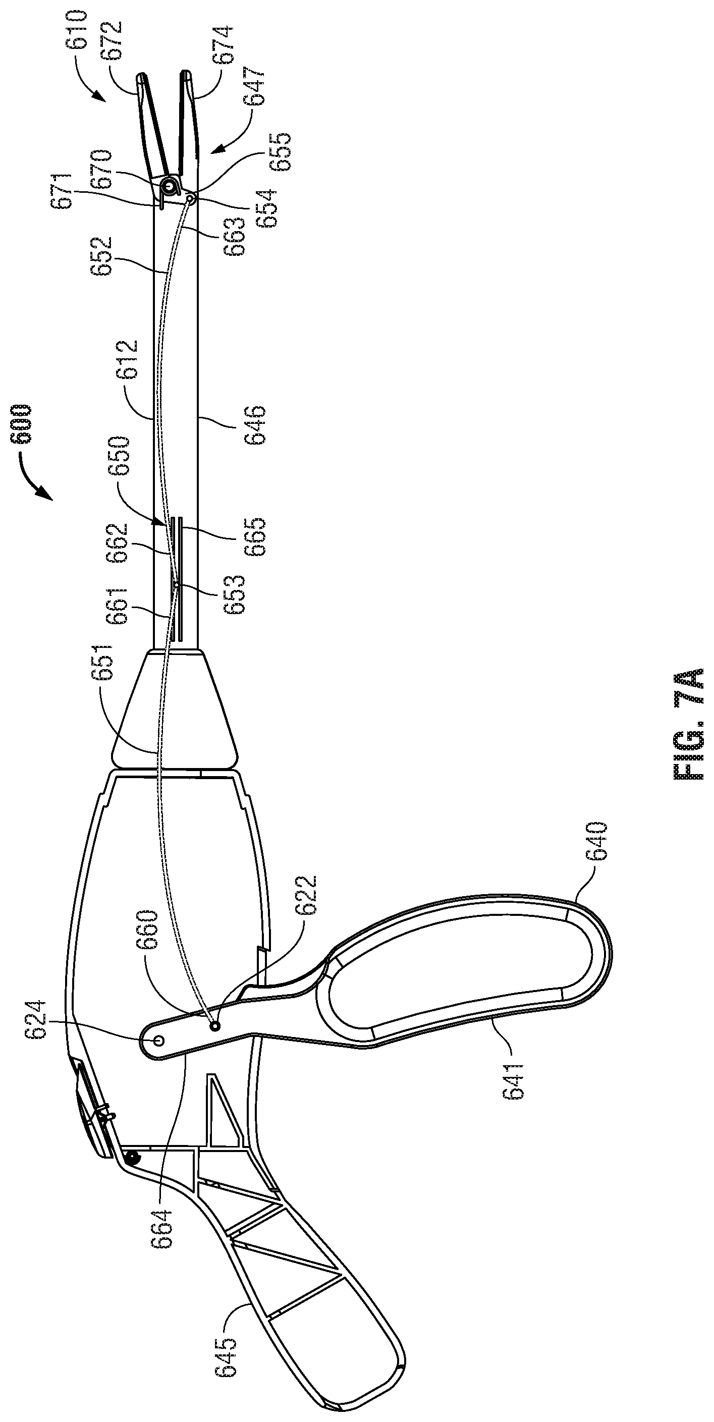
FIG. 7A is a side, cutaway view of an embodiment in accordance with the present disclosure having a hinged spring assembly and an end effector assembly with jaw members positioned in an open configuration;
FIG. 7B is a side, cutaway view of the FIG. 7A embodiment having a hinged spring assembly and an end effector assembly with jaw members positioned in a closed configuration;
FIG. 8A is a side, oblique view of a spring in accordance with the present disclosure having a piano hinge and a generally rectangular cross-section;
FIG. 8B is a side, oblique view of a hinged spring in accordance with the present disclosure having a ball and socket hinge and a generally circular cross-section; and
FIG. 9 is a schematic view of an electrosurgical system configured for use with an electrosurgical instrument according to an embodiment of the present disclosure.
DETAILED DESCRIPTION
Detailed embodiments of the present disclosure are disclosed herein; however, the disclosed embodiments are merely examples of the disclosure, which may be embodied in various forms. Therefore, specific structural and functional details disclosed herein are not to be interpreted as limiting, but merely as a basis for the claims and as a representative basis for teaching one skilled in the art to variously employ the present disclosure in virtually any appropriately detailed structure.
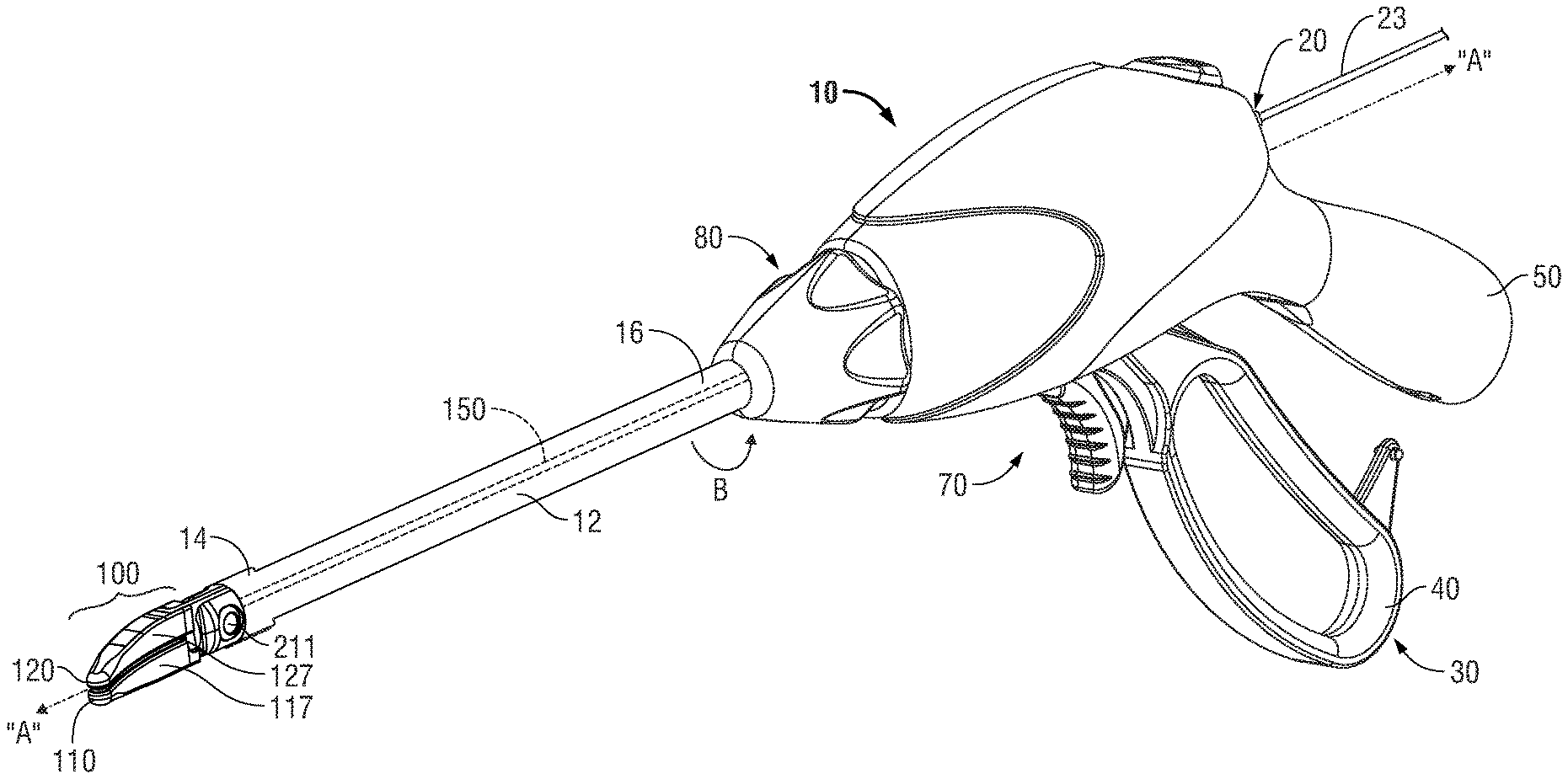
With reference to FIGS. 1A and 1B, an illustrative embodiment of an electrosurgical apparatus, e.g., a bipolar forceps 10 is shown. Forceps 10 is operatively and selectively coupled to a suitable power source, such as, for example, an electrosurgical generator (not shown) for performing an electrosurgical procedure. As noted above, an electrosurgical procedure may include sealing, cutting, cauterizing coagulating, desiccating, and fulgurating tissue all of which may employ RF energy. The generator may be configured for monopolar and/or bipolar modes of operation. The generator may include or is in operative communication with a system 1 (FIG. 9) that may include one or more processors in operative communication with one or more control modules that are executable on the processor. The control module (not explicitly shown) may be configured to instruct one or more modules to transmit electrosurgical energy, which may be in the form of a wave or signal/pulse, via one or more cables (e.g., cable 23) to the forceps 10.
Forceps 10 is shown configured for use with various electrosurgical procedures and generally includes a housing 20, electrosurgical cable 23 that connects the forceps 10 to a source of electrosurgical energy, e.g., electrosurgical generator 2, a handle assembly 30, a rotating assembly 80, a trigger assembly 70, a drive assembly 130, and an end effector assembly 100 that operatively connects to a drive element 150 of the drive assembly 130 (see FIG. 1B). End effector assembly 100 includes opposing jaw members 110 and 120 (FIGS. 1A and 1B) that mutually cooperate to grasp, seal, and in some cases, divide large tubular vessels and large vascular tissues. One or both electrically conductive seal plates 118 and 128 are electrically coupled to a conductor of electrosurgical cable 23 by one or more lead wires (not explicitly shown) to facilitate delivery of electrosurgical energy from generator 2 to targeted tissue. The drive assembly 130 is in operative communication with handle assembly 30 for imparting movement of one or both of a pair of jaw members 110, 120 of end effector assembly 100. Conventional drive assemblies typically utilize one or more types of springs, e.g., a compression spring 131, to facilitate closing the jaw members 110 and 120. For illustrative purposes, compression spring 131 (see FIG. 1B) is shown separated from the housing 20.
With continued reference to FIGS. 1A and 1B, forceps 10 includes a shaft 12 that has a distal end 14 configured to mechanically engage the end effector assembly 100 and a proximal end 16 that mechanically engages the housing 20. In the drawings and in the descriptions that follow, the term "proximal," as is traditional, will refer to the end of the forceps 10 which is closer to the user, while the term "distal" will refer to the end that is farther from the user.
Handle assembly 30 includes a fixed handle 50 and a movable handle 40. Fixed handle 50 is integrally associated with housing 20 and handle 40 is movable relative to fixed handle 50. Movable handle 40 of handle assembly 30 is ultimately connected to the drive assembly 130, which together mechanically cooperate to impart movement of one or both of the jaw members 110 and 120 to move from a clamping or closed position (FIG. 1A), wherein the jaw members 110 and 120 cooperate to grasp tissue therebetween, to an open position (FIG. 1B), wherein the jaw members 110 and 120 are disposed in spaced relation relative to one another.
Jaw members 110, 120 are operatively and pivotably coupled to each other and located adjacent the distal end 14 of shaft 12. Respective electrically conductive seal plates 118 and 128 are operably supported on and secured to respective jaw housings 117 and 127 of respective the jaw members 110 and 120, described in greater detail below. For the purposes herein, jaw members 110 and 120 include jaw housings 117 and 127 that are configured to support sealing plates 118 and 128, respectively.
For a more detailed description of the forceps 10 including handle assembly 30 including movable handle 40, rotating assembly 80, trigger assembly 70, drive assembly 130, jaw members 110 and 120 (including coupling methods utilized to pivotably couple the jaw members 110 and 120 to each other) and electrosurgical cable 23 (including line-feed configurations and/or connections), reference is made to commonly-owned U.S. Pat. No. 7,766,910 issued on Aug. 3, 2010.
Turning now to FIG. 2, one embodiment of jaw housings 117 and 127 is shown. It should be noted that in accordance with the present disclosure one or both of the jaw housings 117 and 127 may include a proximal end that is configured to support one or more cam slots 202 and resilient members 204 to facilitate closing in of the jaw members 110 and 120. Jaw members 110 and 120 are substantially identical to each other, and, in view thereof, and so as not to obscure the present disclosure with redundant information, the operative components associated with the jaw housing 117 are described in further detail with respect to jaw member 110, and only those features distinct to jaw member 120 and jaw housing 127 will be described hereinafter.
With continued reference to FIG. 2, jaw member 110, jaw housing 117, and operative components associated therewith may be formed from any suitable material, including but not limited to metal, metal alloys, plastic, plastic composites, etc. In the embodiment illustrated in FIG. 2, jaw member 110 is formed from metal.
Jaw housing 117 of jaw member 110 is configured to securely engage the electrically conductive seal plate 118. A portion of a proximal flange 117b of the jaw member 110 is operably secured to the distal end 14 of the shaft 12. More particularly, a portion of proximal flange 117b operably couples to the distal end 14 and is in operative communication with the drive element 150 of the drive assembly 130 such that movement of the drive element 150 causes one or both of the jaw members 110 and 120 to move from the closed or clamping position to the open position and vice versa. For example, in one particular embodiment, when the drive element 150 is "pulled," i.e., moved or translated proximally, one or both of the jaw members 110 and 120 is/are caused to move away from the other. Alternatively, and if desired, the drive assembly 130 including the drive element 150 may be configured such that when the drive element 150 is "pushed," i.e., moved or translated distally, one or both of the jaw members 110 and 120 are caused to move away from each other. In certain instances, it may prove useful to have a drive element 150 that is flexible. More particularly, where the drive element 150 is operatively associated with an endoluminal instrument, the drive element 150 may be substantially flexible to accommodate bends typically associated with that type of instrument when the bipolar forceps 10 is remotely actuatable relative to the patient.
In the illustrated embodiment, proximal flange 117b of the jaw housing 110 includes a generally elongated configuration that may be rectangular, circumferential or a combination thereof in shape.
Proximal end 117b of the jaw member 110 includes one or more cam slots 202 defined therein that support one or more cam members 205 (see FIG. 2). More particularly, cam slot 202 is of suitable proportion and configured to receive cam member 205 and is operably formed and/or positioned near the proximal flange 117b of the jaw housing 117. Cam slot 202 includes a generally oblique configuration with respect to a longitudinal axis "B-B" that is parallel to a longitudinal axis "A-A" defined through the shaft 12, see FIGS. 1A and 2. Cam slot 202 may extend at an angle that ranges from about 5.degree. to about 60.degree. with respect to the longitudinal axis "B-B." In the embodiment illustrated FIG. 2, cam slot 202 extends at an angle that is approximately equal to 45.degree. with respect to the longitudinal axis "B-B." The angle of the cam slot 202 may be selectively varied depending upon a particular instrument, use or manufacturing preference.
An opening 208 is defined in and extends through the proximal flange 117b of jaw housing 117 and is configured to receive a spring pin 211. Opening 208 is shown engaged with spring pin 211 and as such is not explicitly visible. In the embodiment illustrated in FIG. 2, a portion of the spring pin 211 is dimensioned to securely engage the resilient member 204 (shown in phantom).
One or more types of resilient members 204 may be operably associated with the housing 117 and include, for example, a torsion spring that is utilized to generate a closure force on the jaw members 110 and 120 when the jaw members 110 and 120 are in a closed or clamped position. The resilient member 204 cooperates with the drive assembly 130 to provide the necessary closure force on the jaw members 110 and 120 for sealing tissue, e.g., in the range of about 3 kg/cm.sup.2 to about 16 kg/cm.sup.2.
Resilient member 204 operably engages jaw housings 117 and 127 and is biased in a closed orientation. More particularly, a proximal end 212 of suitable proportion and having a generally circumferential configuration is dimensioned to securely couple to the spring pin 211. Two generally elongated fingers 214 and 216 (shown in phantom) extend from proximal end 212 adjacent the proximal ends of the jaw members, e.g., proximal flange 117b of jaw member 110 and a proximal flange (not explicitly shown) of the jaw member 120, and fixedly couple to a respective jaw member, e.g., jaw member 117 and jaw member 120. In the embodiment illustrated in FIG. 2, the resilient member 204 biases the jaw members 110 and 120 toward each other to a closed position such that a consistent uniform seal pressure is generated to effectively seal tissue. More particularly, the configuration of the resilient member 204 is designed such that each the elongated fingers 214 and 216 are operably disposed adjacent a respective imaginary center-line "CL" that extends through each of the jaw members 110 and 120, see FIG. 2. In this instance, the force from each of the elongated fingers 214 and 216 is evenly distributed to and throughout each respective jaw member.
One or more types of lubricious materials (not shown), e.g., polytetrafluoroethylene (PTFE), may coat cam slot 202 or an inner peripheral surface thereof. Coating the cam slot 202 with the lubricious material facilitates movement of the cam member 205 within the cam slot 202 when the drive element 150 is translated proximally (or distally depending on a particular configuration).
In an assembled configuration each of the jaw members 110 and 120 is positioned in side-by-side relation. Cam member 205 is operably disposed within cam slot 202 associated with jaw member 110 and a corresponding cam slot (not explicitly shown) associated with jaw member 120. Spring pin 211 is positioned within the opening associated with jaw member 110 and a corresponding opening (not explicitly shown) associated with jaw member 120. As noted above, the spring pin 211 provides a pivot for each of the jaw members 110 and 120. Once assembled, the jaw members 110 and 120 may be pivotably supported at the distal end 14 of the shaft 12 by known methods, such as, for example, by the method described in commonly-owned U.S. Patent Publication No. 2007/0260242 filed on Jul. 11, 2007.
In use, initially jaw members 110 and 120 are biased in a closed position under the closure and/or sealing force provided by the resilient member 204. Proximal movement of movable handle 40 causes the drive element 150 to move proximally. Proximal movement of the drive element 150 causes cam member 205 positioned within the cam slot 202 to move proximally against the bias of the resilient member 204, which, in turn, causes both of the jaw members 110 and 120 to move relative to one another, such that tissue is positionable between the jaw members 110 and 120. Once tissue is positioned between the jaw members 110 and 120 the movable handle 40 is released, which, in turn, causes the jaw members 110 and 120 to move toward one another under the biasing force of the resilient member 204 which generates a sealing or closure force on the tissue disposed between the jaw members 110 and 120. The resilient member 204 provides an additional mechanical advantage at the jaw members 110 and 120 and reduces any frictional losses that are typically associated with conventional forceps when a drive rod is translated within a shaft to make the necessary closure force to seal tissue, e.g., the closure force is offloaded and/or diminished by the resilient member 204.
With reference to FIGS. 3A and 3B, another embodiment of an end effector 300 configured for use with the forceps 10 is illustrated. End effector 300 is substantially identical to end effector 100, and, in view thereof, and so as not to obscure the present disclosure with redundant information, only those features distinct to end effector 300 will be described hereinafter.
End effector 300 includes jaw members 310 and 320. As described above with respect to jaw members 110 and 120, jaw members 310 and 320 are pivotably coupled to each other via a spring pin or pivot pin 311. More particularly, pivot pin 311 operably couples the jaw members 310 and 320 about a medial portion of respective jaw housings 317 and 327 (FIG. 3A). Pivot pin 311 maintains the jaw members 310 and 320 in a substantially fixed position with respect to the longitudinal axis "A-A" when the jaw members 310 and 320 are pivoted or rotated about the pivot pin 311 (see FIGS. 1A and 1B). That is, the jaw members 310 and 320 do not translate along the longitudinal axis "A-A" when movable handle 40 is moved.
A respective cam follower 313 and 323 is operably disposed at a respective proximal end 317b and 327b of the jaw members 310 and 320, respectively. In the embodiment illustrated in FIGS. 3A and 3B, the cam followers 313 and 323 are configured to rotate the respective jaw members 310 and 320 from an open position (FIG. 3A) to a clamping position (FIG. 3B) when the movable handle 40 is moved proximally. Cam followers 313 and 323 are proportioned to movably couple to a cam assembly 330.
Cam assembly 330 translates or moves along the longitudinal axis "A-A" when the movable handle 40 is moved proximally and/or distally. To this end, cam assembly 330 is suitably shaped and proportioned to movably reside within the shaft 12 adjacent the distal end 14. For illustrative purposes, cam assembly 330 is shown elongated with a generally rectangular shape. One or more cam slots 332 are operably disposed on or defined in the cam assembly 330. In the embodiment illustrated in FIGS. 3A and 3B, two intersecting cam slots 332a and 332b are defined in the cam assembly 330. The cam slots 332a and 332b are proportioned to receive respective cam followers 313 and 323 such that cam followers 313 and 323 are movable along a length of the respective cam slots 332a and 332b.
Each of the cam slots 332a and 332b includes a respective distal end 334 and 336. The distal ends 334 and 336 are configured to function as latches. More particularly, the distal ends 334 and 336 maintain the respective cam followers 313 and 323 in a substantially fixed position after the movable handle 40 is moved a predetermined distance proximally and the jaw members 310 and 320 are in the clamping position.
For example, and in one particular embodiment, one or more stop members 335 may be operably disposed along an internal surface of the shaft 12. In this instance, stop member 335 may be configured to contact a portion, e.g., a bottom surface 331, of the cam assembly 330 when the movable handle 40 is moved through an "unlatching" stroke, see FIGS. 3A and 3B. Accordingly, when movable handle 40 is moved through the "unlatching" stroke, the stop member 335 contacts the bottom surface 331 of cam assembly 330, thereby defining the maximum proximal extent of the range of motion of cam assembly 330, which, in turn, defines the maximum opening dimension (e.g., maximum opening angle) of jaws 317, 327 (FIG. 3A). Other latching and unlatching devices and/or configurations may be utilized to latch and unlatch the cam followers 313 and 323 from the respective distal ends 334 and 336.
One or more types of resilient members 304 operably couple to the drive element 150 and to the cam assembly 330. Resilient member 304 may be any suitable resilient member, e.g., a compression spring. A distal end of the drive element 150 operably couples to a proximal end of the resilient member 304 and proximal end of the cam assembly 330 operably couples to a distal end of the resilient member 304. The resilient member 304 operably couples to the distal end of the drive element 150 and proximal end of the cam assembly 330 via any suitable coupling methods. As described above with resilient member 204, resilient member 304 cooperates with the drive assembly 130 to provide the necessary closure force on the jaw members 310 and 320 for sealing tissue, e.g., in the range of about 3 kg/cm.sup.2 to about 16 kg/cm.sup.2.
In use, initially jaw members 310 and 320 are biased in an open position (FIG. 3A). Tissue is positioned between the jaw members 310 and 320. Thereafter, the movable handle 40 is moved proximally causing the drive element 150 to move proximally. Proximal movement of the drive element 150 moves the resilient member 304 proximally, which, in turn, moves the cam assembly 330 proximally. Proximal movement of the cam assembly 330 causes the detents 313 and 323 to move within the respective cam slots 332a and 332b until the detents 313 and 323 are latched into a closed or clamping position (FIG. 3B). In the latched position, the requisite closure force is placed onto the tissue disposed between the jaw members 310 and 320. Thereafter, electrosurgical energy is transmitted to seal surfaces 318 and 328 operably associated with respective jaw members 310 and 320 such that a desired tissue effect, e.g., a tissue seal, may be achieved on the tissue disposed between the jaw members 310 and 320. To open the jaw members 310 and 320, the moveable handle 40 is moved through an "unlatching" stroke that retracts the cam followers 313 and 323 from the respective distal ends 334 and 336 such that the jaw members 310 and 320 return to the initial open position.
With reference to FIGS. 4A and 4B, another embodiment of an end effector 400 that is configured for use with the forceps 10 is illustrated. End effector 400 is substantially identical to end effectors 100 and 300, and, in view thereof, and so as not to obscure the present disclosure with redundant information, only those features distinct to end effector 400 will be described hereinafter.
End effector 400 includes jaw members 410 and 420. In the embodiment illustrated in FIGS. 4A and 4B, one of the jaw members, e.g., jaw members 420, is movable, and one of the jaw members, e.g., jaw member 410, is stationary. This configuration of jaw members 420 and 410 may be reversed to accommodate various surgical procedures. Jaw members 410 and 420 are pivotably coupled to one another via a pivot pin 411.
A support structure 430 is operably disposed along an internal frame of the shaft 12 adjacent the distal end 14. More particularly, the support structure 430 is operably coupled to a top portion of the internal frame of the shaft 12. Support structure 430 is configured to mechanically communicate with a resilient member 404. More particularly, the support structure 430 provides a substantially rigid surface that is configured to compress the resilient member 404 when the resilient member 404 is moved proximally and the movable jaw member 420 is moved to the open position. To this end, support structure 430 may have any suitable shape. In the embodiment illustrated in FIGS. 4A and 4B, support structure 430 includes a generally circumferential configuration having an aperture 406 of suitable proportion defined therethrough. Aperture 406 includes a diameter that is sized to receive the drive element 150 (or portion thereof) that includes a distal end that operably couples to a proximal end 427b of the movable jaw member 420. More particularly, the diameter of the aperture 406 is such that the drive element 150 is movable through the aperture 406 when the movable handle 40 is moved proximally and/or distally. Additionally, the aperture 406 is proportioned such that the resilient member 404 is prevented from translating therethrough when the movable handle 40 is moved proximally and/or distally.
In the embodiment illustrated in FIGS. 4A and 4B, the support structure 430 is configured to maintain the drive element 150 in a substantially fixed off-set orientation above the pivot pin 411, see FIG. 4A, for example. Having the support structure 430 configured in such a manner facilitates moving the jaw member 420 about the pivot pin 411.
Resilient member 404 is operably disposed between the support structure 430 and the proximal end 427b of the jaw housing 427. In an uncompressed state, resilient member 404 cooperates with the support structure 430 to provide the necessary closure force on the jaw members 410 and 420 for sealing tissue, e.g., in the range of about 3 kg/cm.sup.2 to about 16 kg/cm.sup.2. To this end, the resilient member 404 may be any suitable resilient spring, e.g., a compression spring 404, including, but not limited to those previously described herein. The compression spring 404 is proportioned such that the drive element 150 is positionable therethrough, FIG. 4A.
In use, initially jaw members 410 and 420 are biased in a closed position under the closure and/or sealing force provided by the compression spring 404 (FIG. 4B). Proximal movement of movable handle 40 causes the drive element 150 to move proximally. Proximal movement of the drive element 150 causes the moveable jaw member, e.g., jaw member 420, to move relative to the stationary jaw member, e.g., jaw member 410, such that tissue may be positioned between the jaw members 410 and 420. Once tissue is positioned between the jaw members 410 and 420 the movable handle 40 is released, which, in turn, causes the jaw member 420 to move toward jaw member 410 under the biasing force of the compression spring 404 which generates a closure force on the tissue disposed between the jaw members 410 and 420. The compression spring 404 provides an additional mechanical advantage at the jaw members 410 and 420 and reduces the frictional losses that are typically associated with conventional forceps when a drive rod is translated within a shaft to make the necessary closure force to seal tissue, e.g., the closure force is offloaded and/or diminished by the compression spring 404.
From the foregoing and with reference to the various figure drawings, those skilled in the art will appreciate that certain modifications can also be made to the present disclosure without departing from the scope of the same. For example, other resilient members, e.g., leaf springs, compressed gas, resilient bladder, spring washers and bellows, may be operably associated with any of the aforementioned configurations of utilized to generate a closure or sealing force at the jaw members. Moreover, the resilient members 204, 304 and 404 may work in combination with one or more springs located with the shaft 12 or housing 20 that are operatively associated with the drive assembly 130 to generate the necessary forces associated with tissue sealing.
As best seen in FIG. 5, in order to achieve a desired spacing between the electrically conductive surfaces of the respective jaw members, e.g., jaw members 110 and 120, (i.e., gap distance) and apply a desired force to seal the tissue, one or both of the jaw members 110 and/or 120 may include one or more stop members 350 that limit the movement of the two opposing jaw members 110 and 120 relative to one another. The stop member 350 may be disposed on an inner facing surface of one or both of the jaw members 110 and 120. More particularly, stop member 350 extends from a seal surface 118a of seal plate 118 a predetermined distance according to the specific material properties (e.g., compressive strength, thermal expansion, etc.) to yield a consistent and accurate gap distance during sealing. In the illustrated embodiment, the stop members 350 extend from the seal surfaces 118a and 128a a distance that ranges from about 0.001 inches to about 0.006 inches. The gap distance between opposing sealing surfaces 118a and 128a during sealing may range from about 0.001 inches to about 0.006 inches and, preferably, between about 0.002 and about 0.003 inches. The configuration of a seal surface 118a with stop members 350 facilitates in maintaining a uniform distance between the jaw members 110 and 120 along the length thereof during tissue sealing.
For a more detailed description of the stop members 350 and operative components associated therewith, reference is made to commonly-owned United States Patent Publication No. 2009/0171350, filed Jan. 5, 2009.
With reference to FIGS. 6A and 6B, an embodiment of a drive assembly 500 that is configured for use with forceps 10 is illustrated. End effector 510 is substantially identical to end effectors 100 and 300, and, in view thereof, and so as not to obscure the present disclosure with redundant information, only those features distinct to end effector 510 and drive assembly 500 will be described hereinafter.
The drive assembly includes a proximal drive rod 550 that is configured to translate longitudinally within shaft 512. A handle 540 having a gripping end 541 and an upper end 523 is pivotably mounted on a pivot 524 provided by a handle assembly 545. Upper end 523 of pivoting handle 540 includes a slot 525 defined therein and configured to receive a coupling pin 522 that, in turn, is operatively associated with a proximal end 551 of drive rod 550. By this arrangement, a proximal motion of a gripping end 541 of handle 540 (e.g., a squeezing motion) traverses slot 525 through an arc described by the upper end 523 of handle 540 as it rotates around pivot 524, and thus the cooperation between pin 522 and slot 525 translates drive rod 550 distally. At least a portion of a distal end 552 of drive rod 550 is slidably captured within a proximal portion 531 of guide 530, which confines the motion of drive rod 540 generally to a longitudinal axis of shaft 512.
A cam member 555 is slidably captured within a distal portion 532 of guide 530. A pin 556 associated with cam member 555 engages slots 573 and 575 defined within a proximal portion of jaw member 572 and 574, respectively, to facilitate the translation thereof between a mutually open configuration shown in FIG. 6A and a mutually closed configuration shown in FIG. 6B. As shown in FIGS. 6A and 6B, the orientation of slots 573 and 575 is arranged to cause jaw members 572, 574 to move from an open configuration FIG. 6A to a closed configuration of FIG. 6B as cam member 555 moves from a proximal position to a distal position. Alternatively, slots 573 and 575 may be arranged to cause jaw members 572, 574 to move in an opposite manner, e.g., from an open configuration to a closed configuration as cam member 555 moves from a distal position to a distal position.
Drive rod 550 is coupled to cam member 555 by a resilient member 560 that is captured within a center portion 533 of guide 530. Resilient member 560 may include a compression spring formed from a suitable metallic or non-metallic material, such as without limitation, spring steel, nylon, or fiberglass-epoxy composite. Resilient member 560 may additionally or alternatively be formed from an elastomeric material, such as without limitation, rubber, neoprene, and/or silicone.
During use, as handle 540 is squeezed, drive rod 550 is driven in a distal direction which, in turn, compresses resilient member 560, drives cam member 555 distally, and causes jaw members 572, 574 to move to a closed position. The force transferred from handle 540 and drive rod 550 to jaw members 572, 574 depends at least in part upon the spring rate of resilient member 560. For example, use of a resilient member 560 having a low spring rate (e.g., a relatively soft spring) would result in lower jaw clamping force, which may be suitable for smaller or more fragile tissue applications. Conversely, a higher spring rate (e.g., stiffer) would result in higher gripping forces being applied to tissue. Resilient member 560 may include a spring rate that is generally constant within its limits of elasticity, or, alternatively, may include a variable spring rate (e.g., a progressive spring rate that increases with compression or that decreases with compression). Resilient member 560 may include a step linear spring rate whereby two or more discrete, stepped spring rates are provided.
The disclosed drive arrangement may additionally include an adjustable resilient member 560, that may be adjusted in accordance with the requirements of a particular surgical procedure by changing a spring pre-loading via, e.g., a rotatable adjustment dial provided on the handle (not shown), a rotatable adjustment collar on the shaft 512 (not shown), and/or by providing one or more field-interchangeable resilient members that may be "loaded" into the instrument prior to use.
In yet another embodiment of a drive assembly 600 shown in FIGS. 7A and 7B, end effector 610 is substantially identical to end effectors 100 and 300, and, in view thereof, and so as not to obscure the present disclosure with redundant information, only those features distinct to end effector 610 and drive assembly 600 will be described hereinafter.
In the embodiment shown in FIGS. 7A and 7B, a lower stationary jaw 674 member is coupled to a distal end 647 of an elongated shaft 646. A movable upper jaw member 672 is rotationally translatable about a pivot point 670 to enable upper jaw member 672 to move relative to stationary jaw member 647 between an open position shown in FIG. 7A, and a closed position shown in FIG. 7B suitable for grasping tissue. A resilient member 671 biases upper jaw member 672 towards an open position. In the embodiment shown in FIGS. 7A and 7B, resilient member 671 includes a v-spring having one or more coils disposed about pivot point 670; however, any suitable resilient or spring-like member may be utilized, including without limitation, an elastomeric resilient member (e.g., rubber, silicone, neoprene), a leaf spring, and the like.
Upper jaw member 672 includes a proximal lever portion 655 that in the present embodiment is offset in a generally orthogonal manner to a longitudinal centerline of upper jaw member 672. A jaw spring mount 654 is included with proximal lever portion 655 of upper jaw member 672. A movable handle 640 is pivotably coupled to a housing 645 at a pivot point 624. Handle 640 includes a lever arm 664 that joins a grip portion 641 of the handle 640 to the pivot point 624. Lever arm 664 includes a handle spring mount 622.
A hinged leaf spring 650 operably connects at a proximal end 660 thereof to handle 640, and hinged leaf spring 650 operably connects at a distal end 663 thereof to proximal lever portion 655 of upper jaw member 672. More particularly, hinged leaf spring 650 includes at least a proximal spring section 651 and a distal spring section 652. Proximal spring section 651 and distal spring section 652 may be formed from any suitable resilient material, including without limitation, spring steel, fiber-reinforced composite (e.g., fiberglass, carbon fiber, and the like). Proximal spring section 651 and distal spring section 652 have a generally arcuate shape while in the relaxed state, and may have a flat, rectangular cross-sectional shape that may enhance rigidity and resist torsional forces. In some embodiments, proximal spring section 651 and distal spring section 652 may have a cross-sectional shape that is square, circular, ovoid, or polygonal. As shown in FIG. 8A, embodiments of a hinged spring 850 in accordance with the present disclosure include a first arcuate section 851 and a second arcuate section 852, each having a generally rectangular cross-section 853. A piano hinge 853 joins first arcuate section 851 and a second arcuate section 852. In some embodiments illustrated with reference to FIG. 8B, the hinged spring includes a first arcuate section 851' and a second arcuate section 852'. The arcuate sections 851' and 852' include a generally circular cross-section 853' and/or may be joined by a ball and socket-type hinge 853'.
A proximal end 660 of proximal spring section 651 is joined to a lever arm 664 of handle 640 at handle spring mount 622. A distal end of distal spring section 652 is joined to the proximal lever portion 655 of upper jaw member 672 at jaw spring mount 654. A proximal end 662 of distal spring section 652 is joined by hinge 653 to a distal end 661 of proximal spring section 651. Hinge 653 may include a piano-hinge arrangement, a ball-and-socket arrangement, and/or may include a living hinge. Hinged spring 650 may include two sections, as shown, or, alternatively, hinged spring 650 may include three or more sections joined by a hinge as described hereinabove.
During use, handle 640 may be drawn proximally, which, in turn, applies proximal tensile force to hinged spring 650 that causes the proximal spring section 651 and distal spring section 652 to extend from the relaxed, arcuate profile to a straighter profile. In this manner, a first portion of the proximal motion and/or force of handle 640 is absorbed by hinged spring 650 while the remainder of the proximal portion and/or force of handle 640 is applied to proximal lever portion 655 of upper jaw member 672, which, in turn, rotationally translates upper jaw 672 from an open position (e.g., as shown in FIG. 7A) to a closed position (e.g., FIG. 7B).
Advantageously, the force applied to upper jaw member 672, and thus to tissue grasped therebetween, may be controlled or limited by the selection of materials from which hinged spring 650 is formed and/or the dimensions of the spring sections, e.g., the elastomeric profile of the hinged spring assembly 650. For example, and without limitation, a hinged spring 650 having sections 651, 652 formed from material having a greater spring rate and/or having sections 651, 652 having a greater cross-section may increase the operational clamping force applied by jaw members 672, 674. Conversely, a hinged spring 650 having sections 651, 652 formed from material having a lower spring rate and/or having sections 651, 652 having a smaller cross-section may decrease the operational clamping force applied by jaw members 672, 674. In some embodiments, a first hinged spring section (e.g., a proximal section 651) may possess a first elastomeric profile and a second hinged spring section may possess a second elastomeric profile. By this arrangement, a variable, staged, or stepped application of jaw pressure may be achieved.
Turning now to FIG. 9, an electrosurgical system 1 in accordance with the present disclosure is illustrated. The electrosurgical system 1 includes a generator 2 that is operably coupled to bipolar forceps 10 by a cable 6. Cable 6 is detachably coupled to generator 2 via a connector 3. A footswitch 8 may be employed to provide an input to generator 2. Footswitch 8 is operably coupled to generator 2 via footswitch cable 4 and connector 4. Generator 2 includes a user interface 5 that may include, without limitation, input devices (e.g., switches, pushbuttons, continuously variable controls, touch screen, and the like) and/or displays (e.g., LCD displays, LED displays, alphanumeric displays, graphic displays, and the like). Generator 2 is configured to provide electrosurgical energy, e.g., radiofrequency or microwave energy, to forceps 10. In some embodiments, generator 2 includes the capability to provide an alternating electrosurgical signal in the range of about 200 KHz to about 3.3 MHz range. This electrosurgical signal can be a sinusoidal waveform operating in a continuous mode at a 100% duty cycle, or pulse modulated at a duty cycle of less than 100%. Depending on the surgical objective, the electrosurgical signal may have a 100% duty cycle for maximal cutting effect, may be pulse modulated at duty cycles ranging from 50% to 25% for less aggressive cutting or sealing, or, at a substantially lower duty cycle of approximately 6%, for coagulating or sealing. The electrosurgical signal may also be varied in intensity. The electrosurgical signal is applied to the patient via electrodes in either monopolar mode, or bipolar mode. In bipolar mode, both the active and return electrodes are at the surgical site, such as electrically conductive seal plates 118 and 128 so that the electrosurgical signal passes only through the tissue grasped between the jaw electrodes of the instrument.
While several embodiments of the disclosure have been shown in the drawings, it is not intended that the disclosure be limited thereto, as it is intended that the disclosure be as broad in scope as the art will allow and that the specification be read likewise. Therefore, the above description should not be construed as limiting, but merely as examples of particular embodiments. Those skilled in the art will envision other modifications within the scope and spirit of the claims appended hereto.
* * * * *
D00000
D00001
D00002
D00003
D00004
D00005
D00006
D00007
D00008
D00009
D00010
D00011
D00012
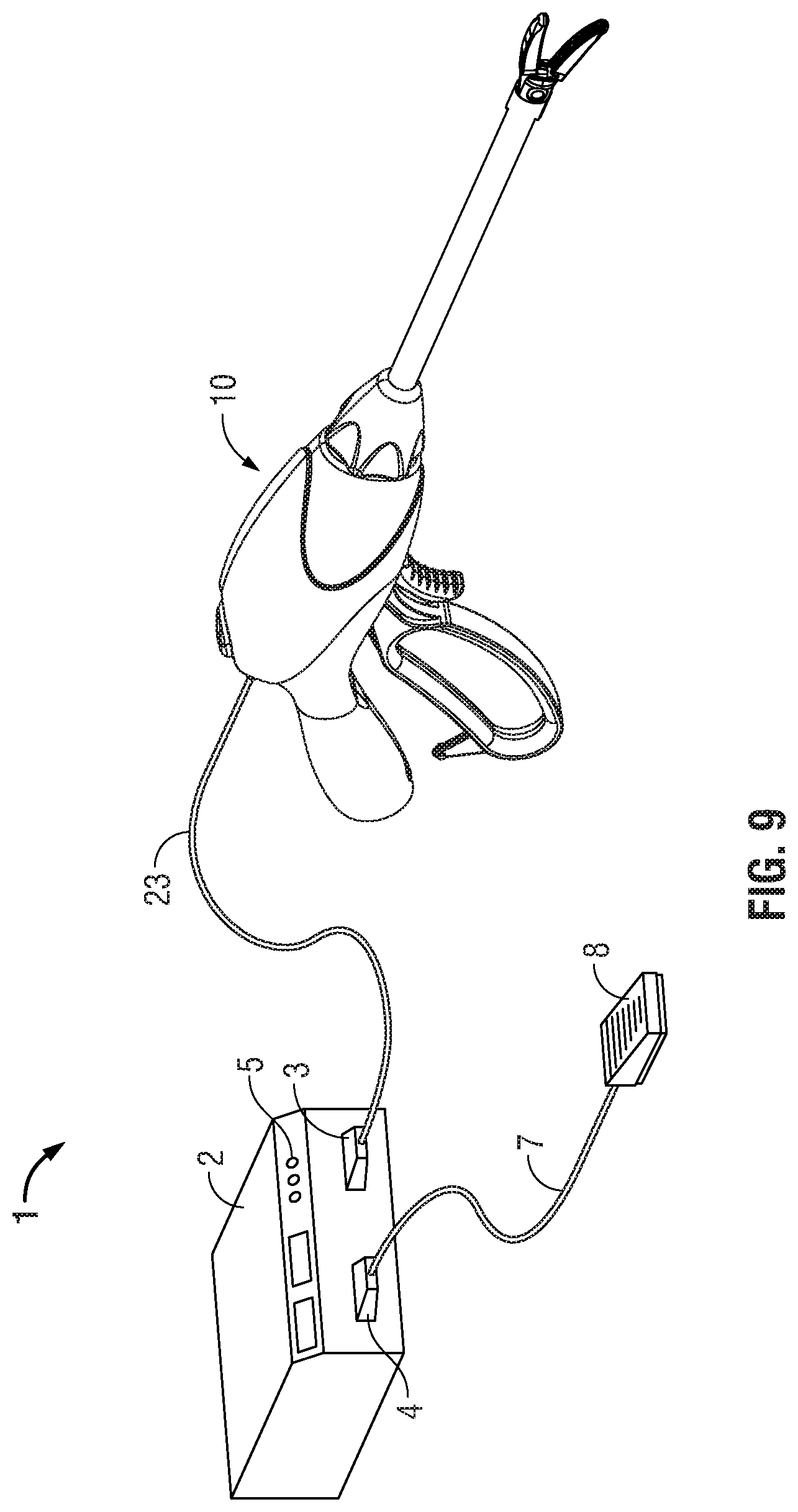
XML
uspto.report is an independent third-party trademark research tool that is not affiliated, endorsed, or sponsored by the United States Patent and Trademark Office (USPTO) or any other governmental organization. The information provided by uspto.report is based on publicly available data at the time of writing and is intended for informational purposes only.
While we strive to provide accurate and up-to-date information, we do not guarantee the accuracy, completeness, reliability, or suitability of the information displayed on this site. The use of this site is at your own risk. Any reliance you place on such information is therefore strictly at your own risk.
All official trademark data, including owner information, should be verified by visiting the official USPTO website at www.uspto.gov. This site is not intended to replace professional legal advice and should not be used as a substitute for consulting with a legal professional who is knowledgeable about trademark law.