Channel equalization enclosure
Sledzinski , et al.
U.S. patent number 10,634,864 [Application Number 15/989,968] was granted by the patent office on 2020-04-28 for channel equalization enclosure. This patent grant is currently assigned to Panduit Corp.. The grantee listed for this patent is Panduit Corp.. Invention is credited to Robert A. Reid, Joseph E. Sanders, Bon B. Sledzinski.

| United States Patent | 10,634,864 |
| Sledzinski , et al. | April 28, 2020 |
Channel equalization enclosure
Abstract
A channel equalization enclosure equalizes the length of cable variance with customers' equipment in a data center. The channel equalization modules serve as a connection point between cable from a financial institution and patch cords connected to customer equipment. The channel equalization enclosure includes a housing and a plurality of channel equalization modules mounted in the housing. Each channel equalization module has a spool of bulk fiber for accommodating a specified fiber length to equalize a communication channel in the data center.
| Inventors: | Sledzinski; Bon B. (Westmont, IL), Reid; Robert A. (Battleground, IN), Sanders; Joseph E. (Elwood, IL) | ||||||||||
|---|---|---|---|---|---|---|---|---|---|---|---|
| Applicant: |
|
||||||||||
| Assignee: | Panduit Corp. (Tinley Park,
IL) |
||||||||||
| Family ID: | 62837973 | ||||||||||
| Appl. No.: | 15/989,968 | ||||||||||
| Filed: | May 25, 2018 |
Prior Publication Data
| Document Identifier | Publication Date | |
|---|---|---|
| US 20180348461 A1 | Dec 6, 2018 | |
Related U.S. Patent Documents
| Application Number | Filing Date | Patent Number | Issue Date | ||
|---|---|---|---|---|---|
| 62512369 | May 30, 2017 | ||||
| Current U.S. Class: | 1/1 |
| Current CPC Class: | G02B 6/4446 (20130101); G02B 6/4454 (20130101); G02B 6/4457 (20130101); G02B 6/4452 (20130101); G02B 6/4471 (20130101) |
| Current International Class: | G02B 6/44 (20060101) |
References Cited [Referenced By]
U.S. Patent Documents
| 5100221 | March 1992 | Carney et al. |
| 6643443 | November 2003 | Holman et al. |
| 7346253 | March 2008 | Bloodworth et al. |
| 7418184 | August 2008 | Gonzales et al. |
| 7702208 | April 2010 | Mudd et al. |
| 7756379 | July 2010 | Kowalczyk et al. |
| 7894701 | February 2011 | Kowalczyk et al. |
| 7936962 | May 2011 | Mudd et al. |
| 7945138 | May 2011 | Hill et al. |
| 8189984 | May 2012 | Kowalczyk et al. |
| 8494333 | July 2013 | Kowalczyk et al. |
| 8705929 | April 2014 | Kowalczyk et al. |
| 8805152 | August 2014 | Smith et al. |
| 8891931 | November 2014 | Kowalczyk et al. |
| 8929708 | January 2015 | Pimentel et al. |
| 9188760 | November 2015 | Kowalczyk et al. |
| 9261663 | February 2016 | Loeffelholz et al. |
| 9261666 | February 2016 | Kowalczyk et al. |
| 9279951 | March 2016 | McGranahan et al. |
| 9329352 | May 2016 | de los Santos Campos et al. |
| 9429729 | August 2016 | Burek et al. |
| 9523834 | December 2016 | Kowalczyk et al. |
| 9563031 | February 2017 | Loeffelholz et al. |
| 9606319 | March 2017 | Kowalczyk et al. |
| 2008/0027201 | January 2008 | Yilgor et al. |
| 2010/0329621 | December 2010 | Makrides-Saravanos et al. |
| 2011/0116081 | May 2011 | Sugimoto |
| 2017/0146763 | May 2017 | Galvan Mijangos et al. |
| 2008027201 | Mar 2008 | WO | |||
| 2011116081 | Sep 2011 | WO | |||
Other References
|
Panduit, Opticom QuickNet Rack Mount Fiber Cassette Enclosures, 2015 (Year: 2015). cited by examiner . He et al., A survey on recent advances in optical communications, Computers and Electrical Engineering 40 (2014) 216-240 (Year: 2901). cited by examiner . Ciena, Low-Latency, High-Performance Optical Networking Solutions, 2011 (Year: 2011). cited by examiner. |
Primary Examiner: Radkowski; Peter
Attorney, Agent or Firm: Clancy; Christopher S. Williams; James H. McVady; Aimee E.
Parent Case Text
CROSS REFERENCE TO RELATED APPLICATIONS
This application claims priority to U.S. Provisional Application Ser. No. 62/512,369, filed May 30, 2017, the subject matter of which is hereby incorporated by reference in its entirety.
Claims
The invention claimed is:
1. A channel equalization enclosure for equalizing a length of cable variance with customers' equipment, the channel equalization enclosure comprising: a housing; and a plurality of channel equalization modules mounted in the housing, each channel equalization module having a spool of bulk fiber secured in the channel equalization module, the spool of bulk fiber includes a specified fiber length that equalizes a communication channel.
2. The channel equalization enclosure of claim 1, wherein the housing has a removable top.
3. The channel equalization enclosure of claim 1, wherein the housing having a front flange for enabling the housing to be mounted to equipment rails.
4. The channel equalization enclosure of claim 1, wherein the channel equalization modules having a tamper resistant label to ensure the channel equalization modules are not altered.
5. The channel equalization enclosure of claim 1, wherein the spool of bulk fiber is terminated with a multifiber connector on one end and a plurality of single fiber connectors at an opposite end.
6. The channel equalization enclosure of claim 5, wherein the multifiber connector is installed in an adapter at a back of each channel equalization module and the plurality of single fiber connectors are installed in adapters at a front of each channel equalization module.
7. The channel equalization enclosure of claim 6, wherein a guard is installed over the adapter and multifiber connector at the back of each channel equalization module to prevent users from altering each channel equalization module.
8. The channel equalization enclosure of claim 1, wherein the channel equalization modules serve as a connection point between cable from a financial institution and patch cords connected to customer equipment.
Description
FIELD OF THE INVENTION
The present invention relates to a fiber optic enclosure, and more particularly to channel equalization modules installed in a fiber optic enclosure.
BACKGROUND OF THE INVENTION
The length of fiber optic cabling can vary between a customers' equipment and the financial institution or stock exchange the equipment is connected to. Financial institutions and stock exchanges are attempting to equalize the cable distance of all the fiber channels within their data center. The financial institutions and stock exchanges need to assure their customers that all data transactions will require the same amount of time to complete. If the financial institutions and stock exchanges fail to equalize the cable variation, some customers would have an advantage over others.
Thus, it is desirable to equalize the length of cable variance with each customers' equipment and the financial institution or the stock exchange.
SUMMARY OF THE INVENTION
A channel equalization enclosure designed to equalize the length of cable variance with customers' equipment in a data center. The channel equalization enclosure includes a housing and a plurality of channel equalization modules mounted in the housing. Each channel equalization module has a spool of bulk fiber to accommodating a specified fiber length to equalize the communication channels between customers' equipment and a financial institution in the data center.
BRIEF DESCRIPTION OF THE DRAWINGS
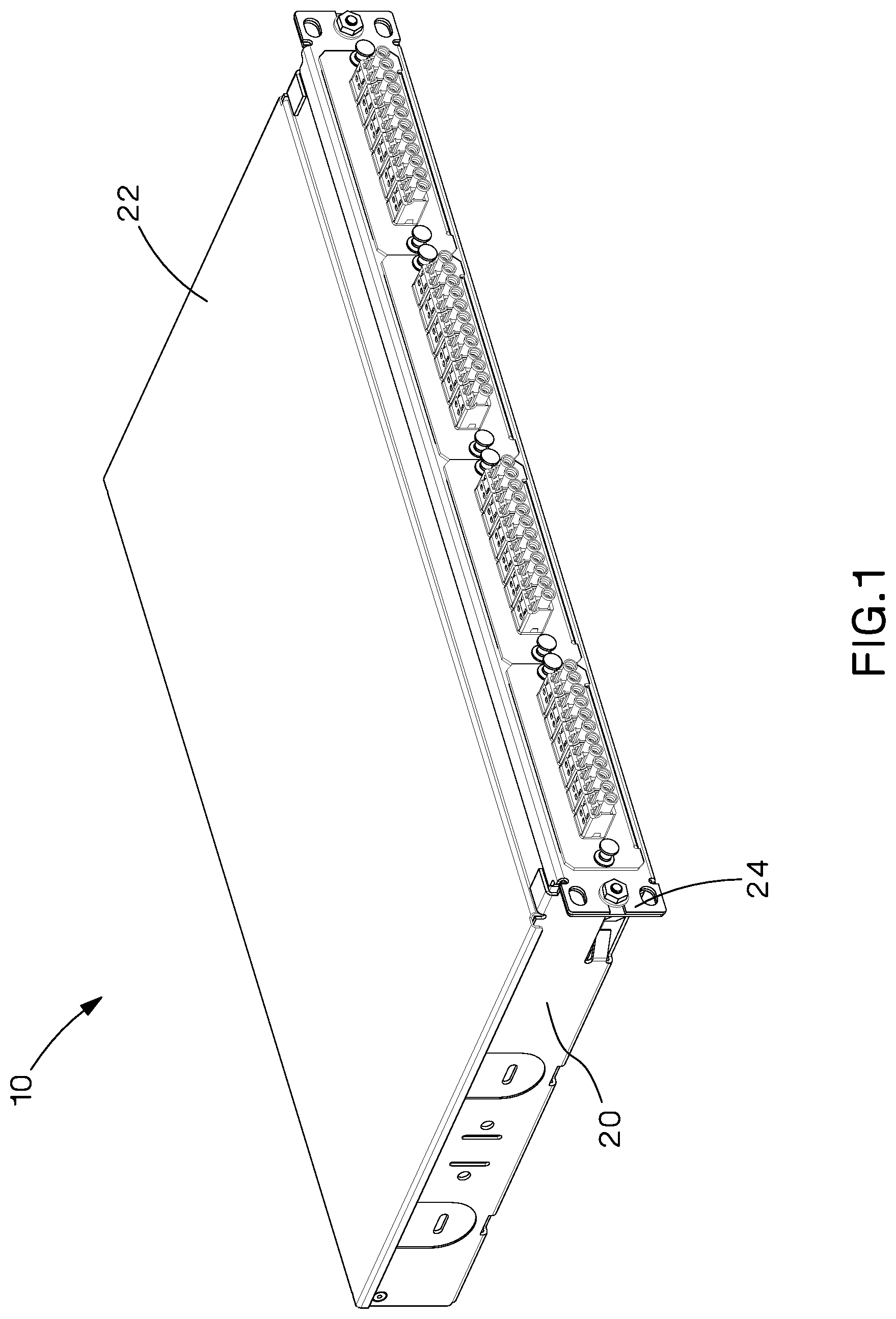
FIG. 1 is a perspective view of a channel equalization enclosure of the present invention.
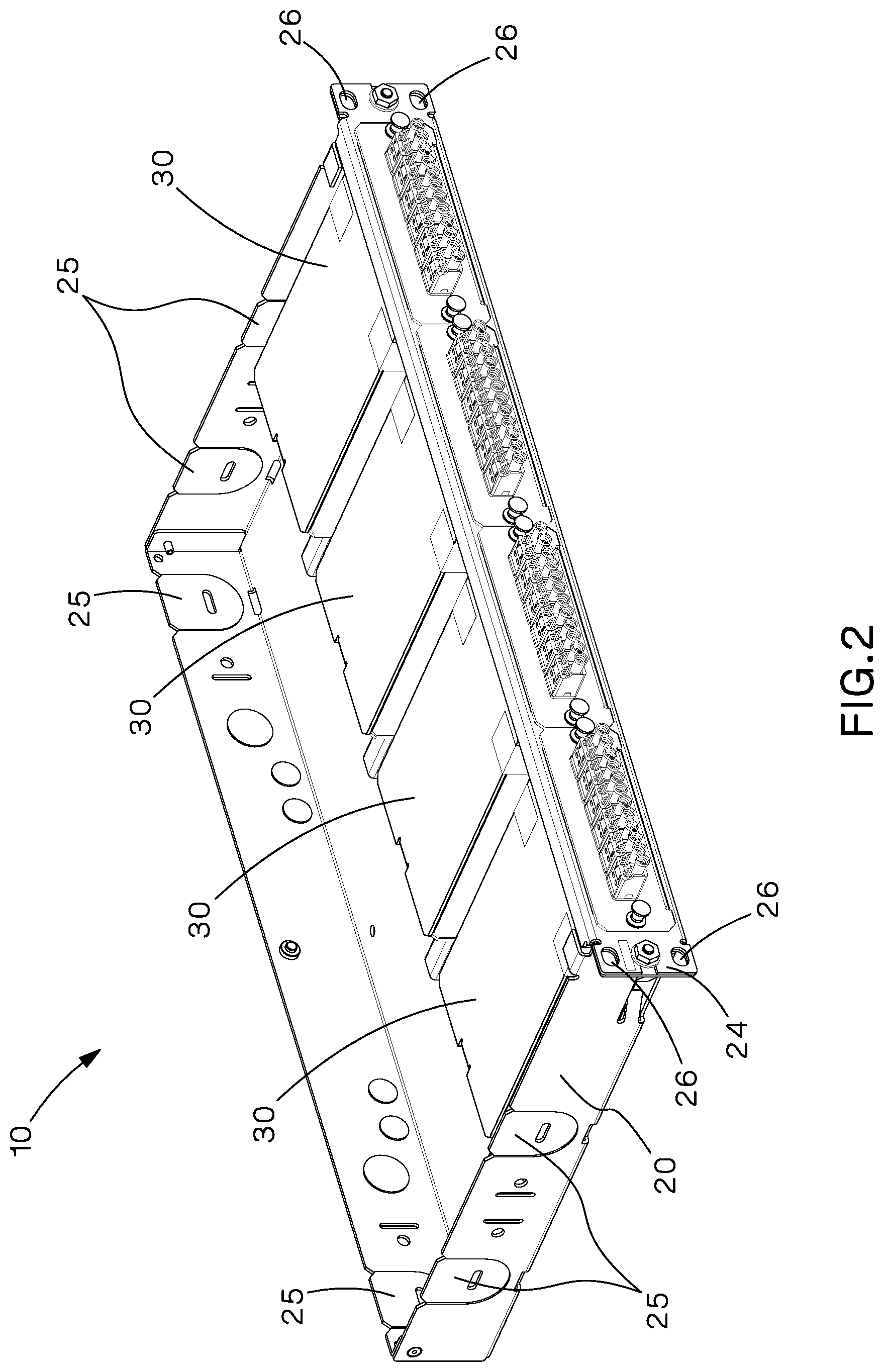
FIG. 2 is a perspective view of the channel equalization enclosure of FIG. 1 with the top removed to illustrate the channel equalization modules.
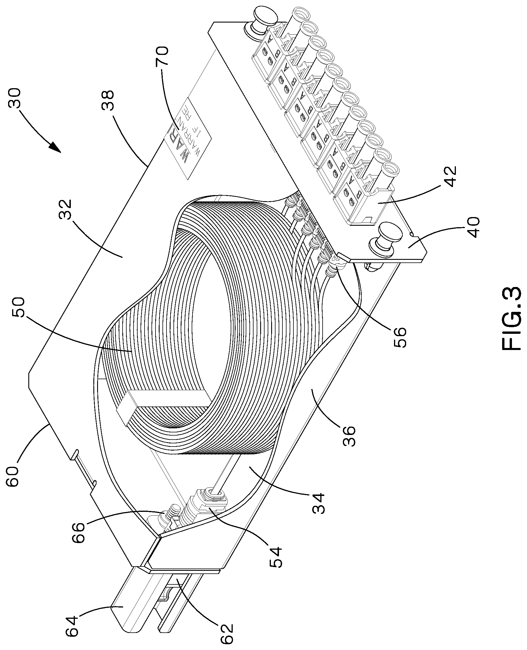
FIG. 3 is a front perspective view of one of the channel equalization modules of FIG. 2.
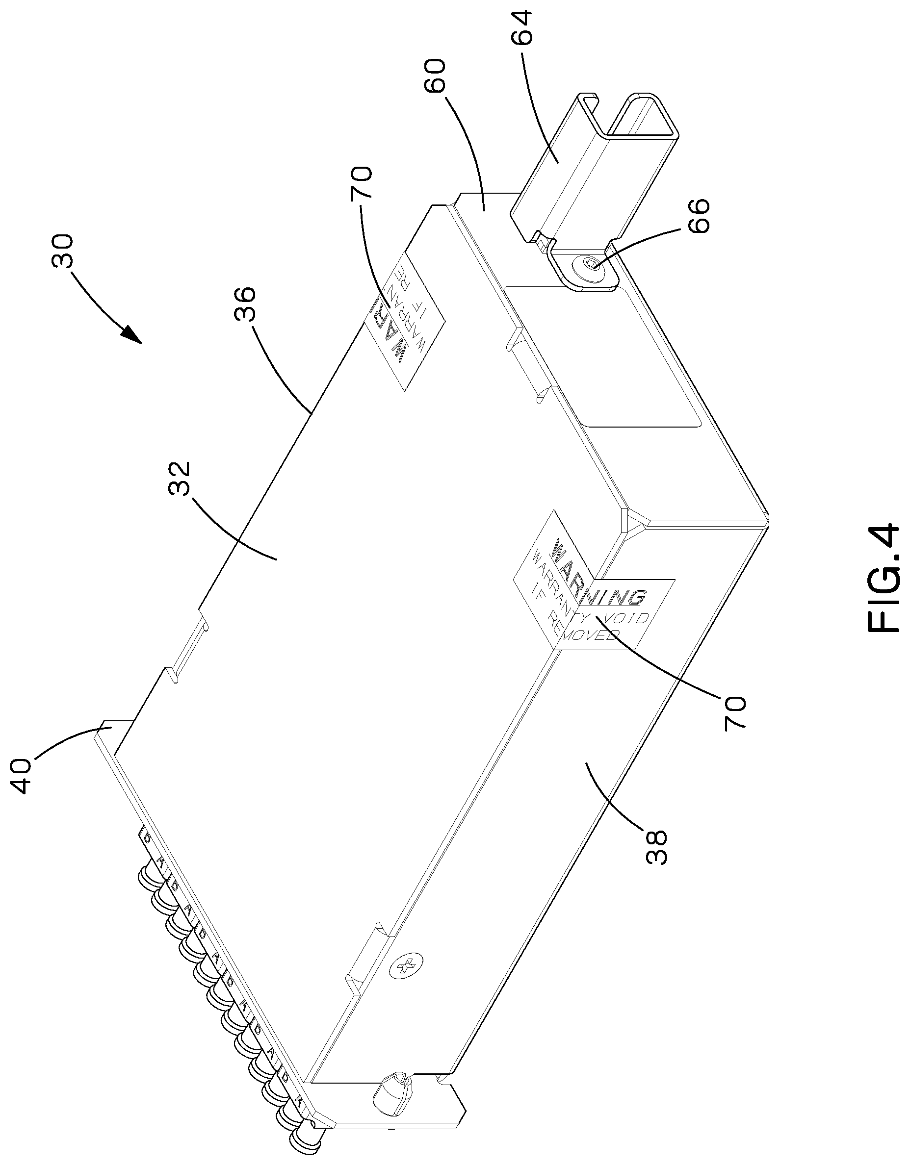
FIG. 4 is a rear perspective view of the channel equalization module of FIG. 3.
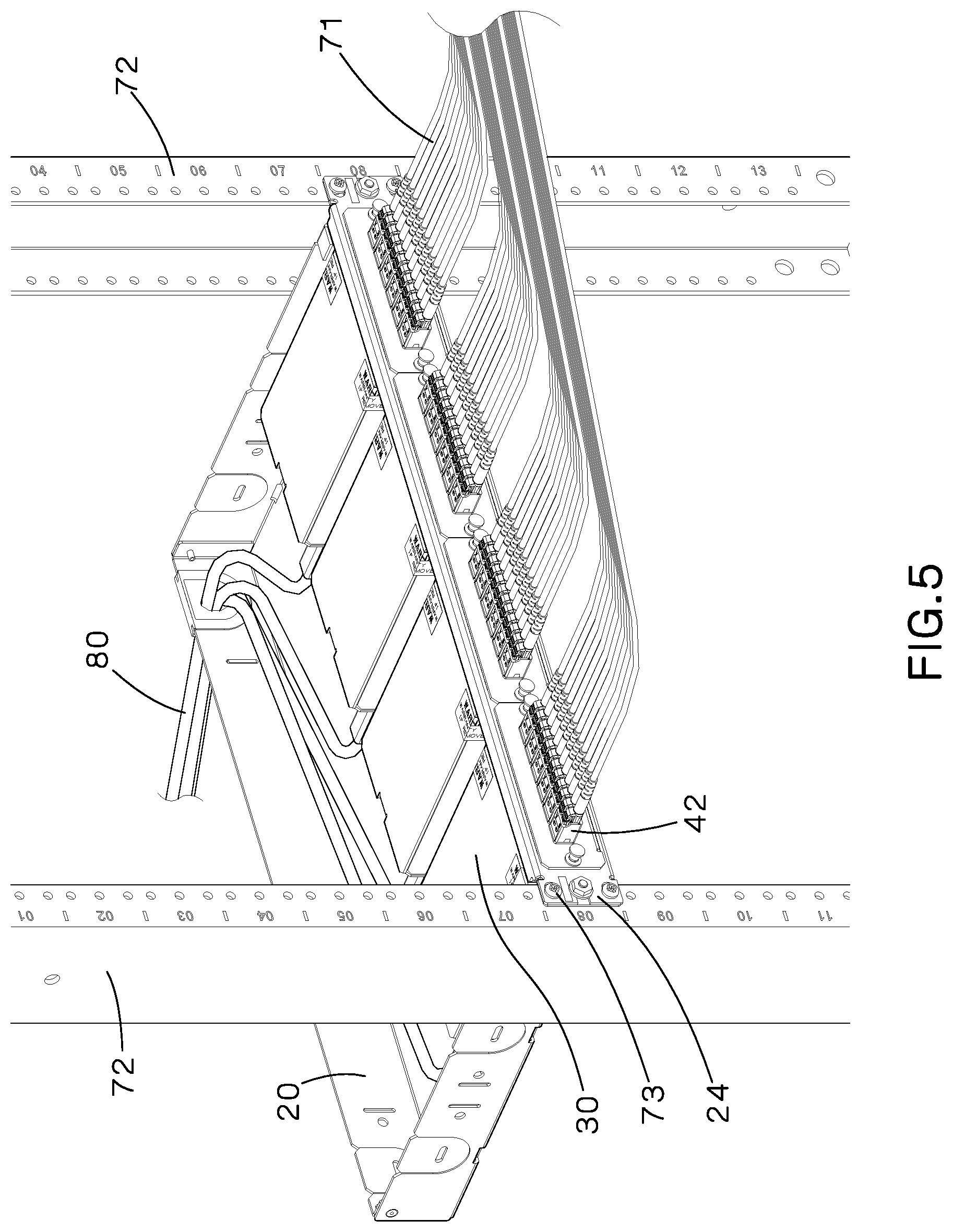
FIG. 5 is a front perspective view of the channel equalization enclosure of FIG. 1, installed on equipment rails and fiber optic cables plugged in, with the top removed to illustrate the channel equalization modules.
DETAILED DESCRIPTION
FIG. 1 illustrates a perspective view of a channel equalization enclosure 10 of the present invention.
FIG. 2 illustrates a perspective view of the channel equalization enclosure 10 with the top removed. The channel equalization enclosure 10 is a sheet metal housing 20 designed to house four channel equalization modules 30. The housing 20 includes a removable top 22 (see FIG. 1) and a front flange 24.
FIG. 3 illustrates one of the channel equalization modules 30. The channel equalization module 30 includes a top 32, a bottom 34, sides 36, 38, a front 40, and a back 60. In FIG. 3, part of the top 32 and part of a side 36 of the channel equalization module 30 are removed so the inside of the module 30 is visible. The channel equalization module 30 includes a spool of slack bulk fiber 50 to accommodate a specific fiber length needed to equalize the communication channel.
For example, if the longest fiber channel in a financial institutions' data center is 230 meters and another fiber channel is 200 meters, the channel equalization module will have an additional 30 meters of slack bulk fiber 50 to make up the difference of the shorter fiber channel.
Once the equalization fiber length is determined, the specific channel equalization module is selected and installed. Each channel equalization module 30 is designed to accommodate specific lengths of fiber cabling. The channel equalization module 30 includes tamper resistance labels 70 to ensure the channel equalization modules 30 are not opened and altered.
The slack bulk fiber 50 will be terminated with a multifiber connector 54 on one end. The multifiber connector 54 would be installed into an adapter 62 in the back 60 of the module 30. The incoming cable from the financial institution is plugged into adapter 62. The opposite end of the slack bulk fiber 50 will be terminated with a plurality of single fiber connectors 56 installed in adapters 42 in the front 40 of the module 30.
As illustrated in FIG. 4, a guard 64 is installed over the multifiber connector adapter 62 in the back 60 of the channel equalization module 30. The guard 64 is secured to the module 30 with a tamper resistant screw 66. The guard 64 covers the release of the multifiber connector adapter 62, making removal of the multi fiber connector adapter 62 very difficult. Thus, the guard 64 prevents users from switching channel equalization modules 30 to alter the equalized channels in the data center.
Referring to FIG. 5, the front flange 24 has mounting holes 26 (see FIG. 2), which allow the channel equalization enclosure to be mounted to standard 19'' equipment rails 72 of a data center cabinet or rack using screws 73. The housing 20 includes knock out holes 25 (see FIG. 2), one or more of which are to be removed to serve as entrance for incoming cable 80 from the financial institution, into the housing 20. The incoming cable 80 from the financial institution is plugged into an adapter 62 (see FIG. 3) in the back of the module 30. The patch cords 71, connected to customers' equipment, are plugged into the single fiber adapters 42 of modules 30.
The channel equalization module 30 will serve as a connection point between the cable from the financial institution or the stock exchange and the patch cords connected to customers' equipment.
Furthermore, while the particular preferred embodiments of the present invention have been shown and described, it will be obvious to those skilled in the art that changes and modifications may be made without departing from the teaching of the invention. The matter set forth in the foregoing description and accompanying drawings is offered by way of illustration only and not as limitation. The actual scope of the invention is intended to be defined in the following claims when viewed in their proper perspective based on the prior art.
* * * * *
D00000
D00001
D00002
D00003
D00004
D00005
XML
uspto.report is an independent third-party trademark research tool that is not affiliated, endorsed, or sponsored by the United States Patent and Trademark Office (USPTO) or any other governmental organization. The information provided by uspto.report is based on publicly available data at the time of writing and is intended for informational purposes only.
While we strive to provide accurate and up-to-date information, we do not guarantee the accuracy, completeness, reliability, or suitability of the information displayed on this site. The use of this site is at your own risk. Any reliance you place on such information is therefore strictly at your own risk.
All official trademark data, including owner information, should be verified by visiting the official USPTO website at www.uspto.gov. This site is not intended to replace professional legal advice and should not be used as a substitute for consulting with a legal professional who is knowledgeable about trademark law.