Systems, devices, and methods for setting cardiac pacing pulse parameters for a cardiac pacing device
Juffer , et al.
U.S. patent number 10,632,313 [Application Number 15/804,699] was granted by the patent office on 2020-04-28 for systems, devices, and methods for setting cardiac pacing pulse parameters for a cardiac pacing device. This patent grant is currently assigned to CARDIAC PACEMAKERS, INC.. The grantee listed for this patent is CARDIAC PACEMAKERS, INC.. Invention is credited to Ron A. Balczewski, Lance Eric Juffer, William J. Linder, Keith R. Maile.


View All Diagrams
| United States Patent | 10,632,313 |
| Juffer , et al. | April 28, 2020 |
Systems, devices, and methods for setting cardiac pacing pulse parameters for a cardiac pacing device
Abstract
Systems, devices, and methods for pacing a heart of a patient are disclosed. A device may include a leadless cardiac pacemaker (LCP) that includes a power supply, a pair of electrodes, and a controller operably connected to the electrodes and the power supply. The controller may identify a capture threshold by setting a pace amplitude at a power supply voltage of the power supply and deliver pacing stimulation pulses with different pulse widths to identify the capture threshold. The LCP may then deliver pacing stimulation pulses based, at least in part, on a pulse amplitude and pulse width associated with the capture threshold, and also adding a capture margin. In some cases, the pulse amplitude may change over time and the LCP may adjust a pulse width along a strength-duration curve to account for the pulse amplitude change and maintain a capture threshold and capture margin.
| Inventors: | Juffer; Lance Eric (Lino Lakes, MN), Linder; William J. (Golden Valley, MN), Balczewski; Ron A. (Bloomington, MN), Maile; Keith R. (New Brighton, MN) | ||||||||||
|---|---|---|---|---|---|---|---|---|---|---|---|
| Applicant: |
|
||||||||||
| Assignee: | CARDIAC PACEMAKERS, INC. (St.
Paul, MN) |
||||||||||
| Family ID: | 60409417 | ||||||||||
| Appl. No.: | 15/804,699 | ||||||||||
| Filed: | November 6, 2017 |
Prior Publication Data
| Document Identifier | Publication Date | |
|---|---|---|
| US 20180126174 A1 | May 10, 2018 | |
Related U.S. Patent Documents
| Application Number | Filing Date | Patent Number | Issue Date | ||
|---|---|---|---|---|---|
| 62419731 | Nov 9, 2016 | ||||
| Current U.S. Class: | 1/1 |
| Current CPC Class: | A61N 1/378 (20130101); A61N 1/3712 (20130101); A61N 1/37512 (20170801); A61N 1/37247 (20130101); A61N 1/3756 (20130101); A61N 1/371 (20130101); A61N 1/3708 (20130101) |
| Current International Class: | A61N 1/37 (20060101); A61N 1/372 (20060101); A61N 1/375 (20060101); A61N 1/378 (20060101) |
References Cited [Referenced By]
U.S. Patent Documents
| 3835864 | September 1974 | Rasor et al. |
| 3943936 | March 1976 | Rasor et al. |
| 4142530 | March 1979 | Wittkampf |
| 4151513 | April 1979 | Menken et al. |
| 4157720 | June 1979 | Greatbatch |
| RE30366 | August 1980 | Rasor et al. |
| 4243045 | January 1981 | Maas |
| 4250884 | February 1981 | Hartlaub et al. |
| 4256115 | March 1981 | Bilitch |
| 4263919 | April 1981 | Levin |
| 4278094 | July 1981 | Zobel |
| 4310000 | January 1982 | Lindemans |
| 4312354 | January 1982 | Walters |
| 4323081 | April 1982 | Wiebusch |
| 4357946 | November 1982 | Dutcher et al. |
| 4365639 | December 1982 | Goldreyer |
| 4440173 | April 1984 | Hudziak et al. |
| 4476868 | October 1984 | Thompson |
| 4522208 | June 1985 | Buffet |
| 4537200 | August 1985 | Widrow |
| 4556063 | December 1985 | Thompson et al. |
| 4562841 | January 1986 | Brockway et al. |
| 4593702 | June 1986 | Kepski et al. |
| 4593955 | June 1986 | Leiber |
| 4630611 | December 1986 | King |
| 4635639 | January 1987 | Hakala et al. |
| 4674508 | June 1987 | DeCote |
| 4712554 | December 1987 | Garson |
| 4729376 | March 1988 | DeCote |
| 4754753 | July 1988 | King |
| 4759366 | July 1988 | Callaghan |
| 4776338 | October 1988 | Lekholm et al. |
| 4787389 | November 1988 | Tarjan |
| 4793353 | December 1988 | Borkan |
| 4819662 | April 1989 | Heil et al. |
| 4858610 | August 1989 | Callaghan et al. |
| 4886064 | December 1989 | Strandberg |
| 4887609 | December 1989 | Cole |
| 4928688 | May 1990 | Mower |
| 4967746 | November 1990 | Vandegriff |
| 4987897 | January 1991 | Funke |
| 4989602 | February 1991 | Sholder et al. |
| 5012806 | May 1991 | De Bellis |
| 5036849 | August 1991 | Hauck et al. |
| 5040534 | August 1991 | Mann et al. |
| 5058581 | October 1991 | Silvian |
| 5078134 | January 1992 | Heilman et al. |
| 5109845 | May 1992 | Yuuchi et al. |
| 5113859 | May 1992 | Funke |
| 5113869 | May 1992 | Nappholz et al. |
| 5117824 | June 1992 | Keimel et al. |
| 5127401 | July 1992 | Grevious et al. |
| 5133353 | July 1992 | Hauser |
| 5144950 | September 1992 | Stoop et al. |
| 5170784 | December 1992 | Ramon et al. |
| 5179945 | January 1993 | Van Hofwegen et al. |
| 5193539 | March 1993 | Schulman et al. |
| 5193540 | March 1993 | Schulman et al. |
| 5241961 | September 1993 | Henry |
| 5243977 | September 1993 | Trabucco et al. |
| 5259387 | November 1993 | DePinto |
| 5269326 | December 1993 | Verrier |
| 5284136 | February 1994 | Hauck et al. |
| 5300107 | April 1994 | Stokes et al. |
| 5301677 | April 1994 | Hsung |
| 5305760 | April 1994 | McKown et al. |
| 5312439 | May 1994 | Loeb |
| 5313953 | May 1994 | Yomtov et al. |
| 5314459 | May 1994 | Swanson et al. |
| 5318597 | June 1994 | Hauck et al. |
| 5324316 | June 1994 | Schulman et al. |
| 5331966 | July 1994 | Bennett et al. |
| 5334222 | August 1994 | Salo et al. |
| 5342408 | August 1994 | deCoriolis et al. |
| 5370667 | December 1994 | Alt |
| 5372606 | December 1994 | Lang et al. |
| 5376106 | December 1994 | Stahmann et al. |
| 5383915 | January 1995 | Adams |
| 5388578 | February 1995 | Yomtov et al. |
| 5404877 | April 1995 | Nolan et al. |
| 5405367 | April 1995 | Schulman et al. |
| 5411031 | May 1995 | Yomtov |
| 5411525 | May 1995 | Swanson et al. |
| 5411533 | May 1995 | Dubreuil et al. |
| 5411535 | May 1995 | Fujii et al. |
| 5447525 | September 1995 | Powell et al. |
| 5456691 | October 1995 | Snell |
| 5458622 | October 1995 | Alt |
| 5466246 | November 1995 | Silvian |
| 5468254 | November 1995 | Hahn et al. |
| 5472453 | December 1995 | Alt |
| 5522866 | June 1996 | Fernald |
| 5540727 | July 1996 | Tockman et al. |
| 5545186 | August 1996 | Olson et al. |
| 5545202 | August 1996 | Dahl et al. |
| 5571146 | November 1996 | Jones et al. |
| 5591214 | January 1997 | Lu |
| 5620466 | April 1997 | Haefner et al. |
| 5634938 | June 1997 | Swanson et al. |
| 5649968 | July 1997 | Alt et al. |
| 5662688 | September 1997 | Haefner et al. |
| 5674259 | October 1997 | Gray |
| 5683426 | November 1997 | Greenhut et al. |
| 5683432 | November 1997 | Goedeke et al. |
| 5706823 | January 1998 | Wodlinger |
| 5709215 | January 1998 | Perttu et al. |
| 5720770 | February 1998 | Nappholz et al. |
| 5728154 | March 1998 | Crossett et al. |
| 5741314 | April 1998 | Daly et al. |
| 5741315 | April 1998 | Lee et al. |
| 5752976 | May 1998 | Duffin et al. |
| 5752977 | May 1998 | Grevious et al. |
| 5755736 | May 1998 | Gillberg et al. |
| 5759199 | June 1998 | Snell et al. |
| 5774501 | June 1998 | Halpern et al. |
| 5792195 | August 1998 | Carlson et al. |
| 5792202 | August 1998 | Rueter |
| 5792203 | August 1998 | Schroeppel |
| 5792205 | August 1998 | Alt et al. |
| 5792208 | August 1998 | Gray |
| 5814089 | September 1998 | Stokes et al. |
| 5827216 | October 1998 | Igo et al. |
| 5836985 | November 1998 | Rostami et al. |
| 5836987 | November 1998 | Baumann et al. |
| 5842977 | December 1998 | Lesho et al. |
| 5843136 | December 1998 | Zhu et al. |
| 5855593 | January 1999 | Olson et al. |
| 5873894 | February 1999 | Vandegriff et al. |
| 5891184 | April 1999 | Lee et al. |
| 5897586 | April 1999 | Molina |
| 5899876 | May 1999 | Flower |
| 5899928 | May 1999 | Sholder et al. |
| 5919214 | July 1999 | Ciciarelli et al. |
| 5935078 | August 1999 | Feierbach |
| 5941906 | August 1999 | Barreras, Sr. et al. |
| 5944744 | August 1999 | Paul et al. |
| 5948004 | September 1999 | Weijand et al. |
| 5954757 | September 1999 | Gray |
| 5978713 | November 1999 | Prutchi et al. |
| 5991660 | November 1999 | Goyal |
| 5991661 | November 1999 | Park et al. |
| 5999848 | December 1999 | Gord et al. |
| 5999857 | December 1999 | Weijand et al. |
| 6016445 | January 2000 | Baura |
| 6026320 | February 2000 | Carlson et al. |
| 6029085 | February 2000 | Olson et al. |
| 6041250 | March 2000 | DePinto |
| 6044298 | March 2000 | Salo et al. |
| 6044300 | March 2000 | Gray |
| 6055454 | April 2000 | Heemels |
| 6073050 | June 2000 | Griffith |
| 6076016 | June 2000 | Feierbach |
| 6077236 | June 2000 | Cunningham |
| 6080187 | June 2000 | Alt et al. |
| 6083248 | July 2000 | Thompson |
| 6106551 | August 2000 | Crossett et al. |
| 6115636 | September 2000 | Ryan |
| 6128526 | October 2000 | Stadler et al. |
| 6141581 | October 2000 | Olson et al. |
| 6141588 | October 2000 | Cox et al. |
| 6141592 | October 2000 | Pauly |
| 6144879 | November 2000 | Gray |
| 6162195 | December 2000 | Igo et al. |
| 6164284 | December 2000 | Schulman et al. |
| 6167310 | December 2000 | Grevious |
| 6201993 | March 2001 | Kruse et al. |
| 6208894 | March 2001 | Schulman et al. |
| 6211799 | April 2001 | Post et al. |
| 6221011 | April 2001 | Bardy |
| 6240316 | May 2001 | Richmond et al. |
| 6240317 | May 2001 | Villaseca et al. |
| 6256534 | July 2001 | Dahl |
| 6259947 | July 2001 | Olson et al. |
| 6266558 | July 2001 | Gozani et al. |
| 6266567 | July 2001 | Ishikawa et al. |
| 6270457 | August 2001 | Bardy |
| 6272377 | August 2001 | Sweeney et al. |
| 6273856 | August 2001 | Sun et al. |
| 6277072 | August 2001 | Bardy |
| 6280380 | August 2001 | Bardy |
| 6285907 | September 2001 | Kramer et al. |
| 6292698 | September 2001 | Duffin et al. |
| 6295473 | September 2001 | Rosar |
| 6297943 | October 2001 | Carson |
| 6298271 | October 2001 | Weijand |
| 6307751 | October 2001 | Bodony et al. |
| 6312378 | November 2001 | Bardy |
| 6315721 | November 2001 | Schulman et al. |
| 6336903 | January 2002 | Bardy |
| 6345202 | February 2002 | Richmond et al. |
| 6351667 | February 2002 | Godie |
| 6351669 | February 2002 | Hartley et al. |
| 6353759 | March 2002 | Hartley et al. |
| 6358203 | March 2002 | Bardy |
| 6361780 | March 2002 | Ley et al. |
| 6368284 | April 2002 | Bardy |
| 6371922 | April 2002 | Baumann et al. |
| 6398728 | June 2002 | Bardy |
| 6400982 | June 2002 | Sweeney et al. |
| 6400990 | June 2002 | Silvian |
| 6408208 | June 2002 | Sun |
| 6409674 | June 2002 | Brockway et al. |
| 6411848 | June 2002 | Kramer et al. |
| 6424865 | July 2002 | Ding |
| 6434429 | August 2002 | Kraus et al. |
| 6438410 | August 2002 | Hsu et al. |
| 6438417 | August 2002 | Rockwell et al. |
| 6438421 | August 2002 | Stahmann et al. |
| 6440066 | August 2002 | Bardy |
| 6441747 | August 2002 | Khair et al. |
| 6442426 | August 2002 | Kroll |
| 6442432 | August 2002 | Lee |
| 6443891 | September 2002 | Grevious |
| 6445953 | September 2002 | Bulkes et al. |
| 6453200 | September 2002 | Koslar |
| 6459929 | October 2002 | Hopper et al. |
| 6470215 | October 2002 | Kraus et al. |
| 6471645 | October 2002 | Warkentin et al. |
| 6480745 | November 2002 | Nelson et al. |
| 6487443 | November 2002 | Olson et al. |
| 6490487 | December 2002 | Kraus et al. |
| 6498951 | December 2002 | Larson et al. |
| 6507755 | January 2003 | Gozani et al. |
| 6507759 | January 2003 | Prutchi et al. |
| 6512940 | January 2003 | Brabec et al. |
| 6522915 | February 2003 | Ceballos et al. |
| 6526311 | February 2003 | Begemann |
| 6539253 | March 2003 | Thompson et al. |
| 6542775 | April 2003 | Ding et al. |
| 6553258 | April 2003 | Stahmann et al. |
| 6561975 | May 2003 | Pool et al. |
| 6564807 | May 2003 | Schulman et al. |
| 6574506 | June 2003 | Kramer et al. |
| 6584351 | June 2003 | Ekwall |
| 6584352 | June 2003 | Combs et al. |
| 6597948 | July 2003 | Rockwell et al. |
| 6597951 | July 2003 | Kramer et al. |
| 6622046 | September 2003 | Fraley et al. |
| 6628985 | September 2003 | Sweeney et al. |
| 6647292 | November 2003 | Bardy et al. |
| 6666844 | December 2003 | Igo et al. |
| 6689117 | February 2004 | Sweeney et al. |
| 6690959 | February 2004 | Thompson |
| 6694189 | February 2004 | Begemann |
| 6704602 | March 2004 | Berg et al. |
| 6718212 | April 2004 | Parry et al. |
| 6721597 | April 2004 | Bardy et al. |
| 6738668 | May 2004 | Mouchawar et al. |
| 6738670 | May 2004 | Almendinger et al. |
| 6746797 | June 2004 | Benson et al. |
| 6749566 | June 2004 | Russ |
| 6758810 | July 2004 | Lebel et al. |
| 6763269 | July 2004 | Cox |
| 6778860 | August 2004 | Ostroff et al. |
| 6788971 | September 2004 | Sloman et al. |
| 6788974 | September 2004 | Bardy et al. |
| 6804558 | October 2004 | Haller et al. |
| 6807442 | October 2004 | Myklebust et al. |
| 6847844 | January 2005 | Sun et al. |
| 6871095 | March 2005 | Stahmann et al. |
| 6878112 | April 2005 | Linberg et al. |
| 6885889 | April 2005 | Chinchoy |
| 6892094 | May 2005 | Ousdigian et al. |
| 6897788 | May 2005 | Khair et al. |
| 6904315 | June 2005 | Panken et al. |
| 6922592 | July 2005 | Thompson et al. |
| 6931282 | August 2005 | Esler |
| 6934585 | August 2005 | Schloss et al. |
| 6957107 | October 2005 | Rogers et al. |
| 6978176 | December 2005 | Lattouf |
| 6985773 | January 2006 | Von Arx et al. |
| 6990375 | January 2006 | Kloss et al. |
| 7001366 | February 2006 | Ballard |
| 7003350 | February 2006 | Denker et al. |
| 7006864 | February 2006 | Echt et al. |
| 7013178 | March 2006 | Reinke et al. |
| 7024246 | April 2006 | Acosta et al. |
| 7027871 | April 2006 | Burnes et al. |
| 7050849 | May 2006 | Echt et al. |
| 7060031 | June 2006 | Webb et al. |
| 7063693 | June 2006 | Guenst |
| 7082336 | July 2006 | Ransbury et al. |
| 7085606 | August 2006 | Flach et al. |
| 7092758 | August 2006 | Sun et al. |
| 7110824 | September 2006 | Amundson et al. |
| 7120504 | October 2006 | Osypka |
| 7130681 | October 2006 | Gebhardt et al. |
| 7139613 | November 2006 | Reinke et al. |
| 7142912 | November 2006 | Wagner et al. |
| 7146225 | December 2006 | Guenst et al. |
| 7146226 | December 2006 | Lau et al. |
| 7149581 | December 2006 | Goedeke |
| 7149588 | December 2006 | Lau et al. |
| 7158839 | January 2007 | Lau |
| 7162307 | January 2007 | Patrias |
| 7164952 | January 2007 | Lau et al. |
| 7177700 | February 2007 | Cox |
| 7181505 | February 2007 | Haller et al. |
| 7184830 | February 2007 | Echt et al. |
| 7186214 | March 2007 | Ness |
| 7191015 | March 2007 | Lamson et al. |
| 7200437 | April 2007 | Nabutovsky et al. |
| 7200439 | April 2007 | Zdeblick et al. |
| 7206423 | April 2007 | Feng et al. |
| 7209785 | April 2007 | Kim et al. |
| 7209790 | April 2007 | Thompson et al. |
| 7211884 | May 2007 | Davis et al. |
| 7212871 | May 2007 | Morgan |
| 7226440 | June 2007 | Gelfand et al. |
| 7228183 | June 2007 | Sun et al. |
| 7236821 | June 2007 | Cates et al. |
| 7236829 | June 2007 | Farazi et al. |
| 7254448 | August 2007 | Almendinger et al. |
| 7260436 | August 2007 | Kilgore et al. |
| 7270669 | September 2007 | Sra |
| 7272448 | September 2007 | Morgan et al. |
| 7277755 | October 2007 | Falkenberg et al. |
| 7280872 | October 2007 | Mosesov et al. |
| 7288096 | October 2007 | Chin |
| 7289847 | October 2007 | Gill et al. |
| 7289852 | October 2007 | Helfinstine et al. |
| 7289853 | October 2007 | Campbell et al. |
| 7289855 | October 2007 | Nghiem et al. |
| 7302294 | November 2007 | Kamath et al. |
| 7305266 | December 2007 | Kroll |
| 7310556 | December 2007 | Bulkes |
| 7319905 | January 2008 | Morgan et al. |
| 7321798 | January 2008 | Muhlenberg et al. |
| 7333853 | February 2008 | Mazar et al. |
| 7336994 | February 2008 | Hettrick et al. |
| 7347819 | March 2008 | Lebel et al. |
| 7366572 | April 2008 | Heruth et al. |
| 7373207 | May 2008 | Lattouf |
| 7384403 | June 2008 | Sherman |
| 7386342 | June 2008 | Falkenberg et al. |
| 7392090 | June 2008 | Sweeney et al. |
| 7406105 | July 2008 | DelMain et al. |
| 7406349 | July 2008 | Seeberger et al. |
| 7410497 | August 2008 | Hastings et al. |
| 7425200 | September 2008 | Brockway et al. |
| 7433739 | October 2008 | Salys et al. |
| 7496409 | February 2009 | Greenhut et al. |
| 7496410 | February 2009 | Heil |
| 7502652 | March 2009 | Gaunt et al. |
| 7512448 | March 2009 | Malick et al. |
| 7515969 | April 2009 | Tockman et al. |
| 7526342 | April 2009 | Chin et al. |
| 7529589 | May 2009 | Williams et al. |
| 7532933 | May 2009 | Hastings et al. |
| 7536222 | May 2009 | Bardy et al. |
| 7536224 | May 2009 | Ritscher et al. |
| 7539541 | May 2009 | Quiles et al. |
| 7544197 | June 2009 | Kelsch et al. |
| 7558631 | July 2009 | Cowan et al. |
| 7565195 | July 2009 | Kroll et al. |
| 7584002 | September 2009 | Burnes et al. |
| 7590455 | September 2009 | Heruth et al. |
| 7606621 | October 2009 | Brisken et al. |
| 7610088 | October 2009 | Chinchoy |
| 7610092 | October 2009 | Cowan et al. |
| 7610099 | October 2009 | Almendinger et al. |
| 7610104 | October 2009 | Kaplan et al. |
| 7616991 | November 2009 | Mann et al. |
| 7617001 | November 2009 | Penner et al. |
| 7617007 | November 2009 | Williams et al. |
| 7630767 | December 2009 | Poore et al. |
| 7634313 | December 2009 | Kroll et al. |
| 7637867 | December 2009 | Zdeblick |
| 7640060 | December 2009 | Zdeblick |
| 7647109 | January 2010 | Hastings et al. |
| 7650186 | January 2010 | Hastings et al. |
| 7657311 | February 2010 | Bardy et al. |
| 7668596 | February 2010 | Von Arx et al. |
| 7682316 | March 2010 | Anderson et al. |
| 7691047 | April 2010 | Ferrari |
| 7702392 | April 2010 | Echt et al. |
| 7713194 | May 2010 | Zdeblick |
| 7713195 | May 2010 | Zdeblick |
| 7729783 | June 2010 | Michels et al. |
| 7734333 | June 2010 | Ghanem et al. |
| 7734343 | June 2010 | Ransbury et al. |
| 7738958 | June 2010 | Zdeblick et al. |
| 7738964 | June 2010 | Von Arx et al. |
| 7742812 | June 2010 | Ghanem et al. |
| 7742816 | June 2010 | Masoud et al. |
| 7742822 | June 2010 | Masoud et al. |
| 7743151 | June 2010 | Vallapureddy et al. |
| 7747335 | June 2010 | Williams |
| 7751881 | July 2010 | Cowan et al. |
| 7758521 | July 2010 | Morris et al. |
| 7761150 | July 2010 | Ghanem et al. |
| 7761164 | July 2010 | Verhoef et al. |
| 7765001 | July 2010 | Echt et al. |
| 7769452 | August 2010 | Ghanem et al. |
| 7783362 | August 2010 | Whitehurst et al. |
| 7792588 | September 2010 | Harding |
| 7797059 | September 2010 | Bornzin et al. |
| 7801596 | September 2010 | Fischell et al. |
| 7809438 | October 2010 | Echt et al. |
| 7840281 | November 2010 | Kveen et al. |
| 7844331 | November 2010 | Li et al. |
| 7844348 | November 2010 | Swoyer et al. |
| 7846088 | December 2010 | Ness |
| 7848815 | December 2010 | Brisken et al. |
| 7848823 | December 2010 | Drasler et al. |
| 7860455 | December 2010 | Fukumoto et al. |
| 7871433 | January 2011 | Lattouf |
| 7877136 | January 2011 | Moffitt et al. |
| 7877142 | January 2011 | Moaddeb et al. |
| 7881786 | February 2011 | Jackson |
| 7881798 | February 2011 | Miesel et al. |
| 7881810 | February 2011 | Chitre et al. |
| 7890173 | February 2011 | Brisken et al. |
| 7890181 | February 2011 | Denzene et al. |
| 7890192 | February 2011 | Kelsch et al. |
| 7894885 | February 2011 | Bartal et al. |
| 7894894 | February 2011 | Stadler et al. |
| 7894907 | February 2011 | Cowan et al. |
| 7894910 | February 2011 | Cowan et al. |
| 7894915 | February 2011 | Chitre et al. |
| 7899537 | March 2011 | Kroll et al. |
| 7899541 | March 2011 | Cowan et al. |
| 7899542 | March 2011 | Cowan et al. |
| 7899554 | March 2011 | Williams et al. |
| 7901360 | March 2011 | Yang et al. |
| 7904170 | March 2011 | Harding |
| 7907993 | March 2011 | Ghanem et al. |
| 7920928 | April 2011 | Yang et al. |
| 7925343 | April 2011 | Min et al. |
| 7930022 | April 2011 | Zhang et al. |
| 7930040 | April 2011 | Kelsch et al. |
| 7937135 | May 2011 | Ghanem et al. |
| 7937148 | May 2011 | Jacobson |
| 7937161 | May 2011 | Hastings et al. |
| 7941214 | May 2011 | Kleckner et al. |
| 7945333 | May 2011 | Jacobson |
| 7946997 | May 2011 | Hubinette |
| 7949404 | May 2011 | Hill |
| 7949405 | May 2011 | Feher |
| 7953486 | May 2011 | Daum et al. |
| 7953493 | May 2011 | Fowler et al. |
| 7962202 | June 2011 | Bhunia |
| 7974702 | July 2011 | Fain et al. |
| 7979136 | July 2011 | Young et al. |
| 7983753 | July 2011 | Severin |
| 7991467 | August 2011 | Markowitz et al. |
| 7991471 | August 2011 | Ghanem et al. |
| 7996087 | August 2011 | Cowan et al. |
| 8000791 | August 2011 | Sunagawa et al. |
| 8000807 | August 2011 | Morris et al. |
| 8001975 | August 2011 | DiSilvestro et al. |
| 8002700 | August 2011 | Ferek-Petric et al. |
| 8010209 | August 2011 | Jacobson |
| 8019419 | September 2011 | Panescu et al. |
| 8019434 | September 2011 | Quiles et al. |
| 8027727 | September 2011 | Freeberg |
| 8027729 | September 2011 | Sunagawa et al. |
| 8032219 | October 2011 | Neumann et al. |
| 8036743 | October 2011 | Savage et al. |
| 8046079 | October 2011 | Bange et al. |
| 8046080 | October 2011 | Von Arx et al. |
| 8050297 | November 2011 | DelMain et al. |
| 8050759 | November 2011 | Stegemann et al. |
| 8050774 | November 2011 | Kveen et al. |
| 8055345 | November 2011 | Li et al. |
| 8055350 | November 2011 | Roberts |
| 8060212 | November 2011 | Rios et al. |
| 8065018 | November 2011 | Haubrich et al. |
| 8073542 | December 2011 | Doerr |
| 8078278 | December 2011 | Penner |
| 8078283 | December 2011 | Cowan et al. |
| 8095123 | January 2012 | Gray |
| 8102789 | January 2012 | Rosar et al. |
| 8103359 | January 2012 | Reddy |
| 8103361 | January 2012 | Moser |
| 8112148 | February 2012 | Giftakis et al. |
| 8114021 | February 2012 | Robertson et al. |
| 8121680 | February 2012 | Falkenberg et al. |
| 8123684 | February 2012 | Zdeblick |
| 8126545 | February 2012 | Flach et al. |
| 8131334 | March 2012 | Lu et al. |
| 8140161 | March 2012 | Willerton et al. |
| 8150521 | April 2012 | Crowley et al. |
| 8160672 | April 2012 | Kim et al. |
| 8160702 | April 2012 | Mann et al. |
| 8160704 | April 2012 | Freeberg |
| 8165694 | April 2012 | Carbanaru et al. |
| 8175715 | May 2012 | Cox |
| 8180451 | May 2012 | Hickman et al. |
| 8185213 | May 2012 | Kveen et al. |
| 8187161 | May 2012 | Li et al. |
| 8195293 | June 2012 | Limousin et al. |
| 8204595 | June 2012 | Pianca et al. |
| 8204605 | June 2012 | Hastings et al. |
| 8209014 | June 2012 | Doerr |
| 8214043 | July 2012 | Mates |
| 8224244 | July 2012 | Kim et al. |
| 8229556 | July 2012 | Li |
| 8233985 | July 2012 | Bulkes et al. |
| 8262578 | September 2012 | Bharmi et al. |
| 8265748 | September 2012 | Liu et al. |
| 8265757 | September 2012 | Mass et al. |
| 8280521 | October 2012 | Haubrich et al. |
| 8285387 | October 2012 | Utsi et al. |
| 8290598 | October 2012 | Boon et al. |
| 8290600 | October 2012 | Hastings et al. |
| 8295939 | October 2012 | Jacobson |
| 8301254 | October 2012 | Mosesov et al. |
| 8315701 | November 2012 | Cowan et al. |
| 8315708 | November 2012 | Berthelsdorf et al. |
| 8321021 | November 2012 | Kisker et al. |
| 8321036 | November 2012 | Brockway et al. |
| 8332036 | December 2012 | Hastings et al. |
| 8335563 | December 2012 | Stessman |
| 8335568 | December 2012 | Heruth et al. |
| 8340750 | December 2012 | Prakash et al. |
| 8340780 | December 2012 | Hastings et al. |
| 8352025 | January 2013 | Jacobson |
| 8352028 | January 2013 | Wenger |
| 8352038 | January 2013 | Mao et al. |
| 8359098 | January 2013 | Lund et al. |
| 8364261 | January 2013 | Stubbs et al. |
| 8364276 | January 2013 | Willis |
| 8369959 | February 2013 | Meskens |
| 8369962 | February 2013 | Abrahamson |
| 8380320 | February 2013 | Spital |
| 8386051 | February 2013 | Rys |
| 8391981 | March 2013 | Mosesov |
| 8391990 | March 2013 | Smith et al. |
| 8406874 | March 2013 | Liu et al. |
| 8406879 | March 2013 | Shuros et al. |
| 8406886 | March 2013 | Gaunt et al. |
| 8412352 | April 2013 | Griswold et al. |
| 8417340 | April 2013 | Goossen |
| 8417341 | April 2013 | Freeberg |
| 8423149 | April 2013 | Hennig |
| 8428722 | April 2013 | Verhoef et al. |
| 8433402 | April 2013 | Ruben et al. |
| 8433409 | April 2013 | Johnson et al. |
| 8433420 | April 2013 | Bange et al. |
| 8446212 | May 2013 | Tranchina et al. |
| 8447412 | May 2013 | Dal Molin et al. |
| 8452413 | May 2013 | Young et al. |
| 8457740 | June 2013 | Osche |
| 8457742 | June 2013 | Jacobson |
| 8457744 | June 2013 | Janzig et al. |
| 8457761 | June 2013 | Wariar |
| 8478407 | July 2013 | Demmer et al. |
| 8478408 | July 2013 | Hastings et al. |
| 8478431 | July 2013 | Griswold et al. |
| 8494632 | July 2013 | Sun et al. |
| 8504156 | August 2013 | Bonner et al. |
| 8509910 | August 2013 | Sowder et al. |
| 8515559 | August 2013 | Roberts et al. |
| 8525340 | September 2013 | Eckhardt et al. |
| 8527068 | September 2013 | Ostroff |
| 8532790 | September 2013 | Griswold |
| 8538526 | September 2013 | Stahmann et al. |
| 8541131 | September 2013 | Lund et al. |
| 8543205 | September 2013 | Ostroff |
| 8547248 | October 2013 | Zdeblick et al. |
| 8548605 | October 2013 | Ollivier |
| 8554333 | October 2013 | Wu et al. |
| 8565882 | October 2013 | Matos |
| 8565897 | October 2013 | Regnier et al. |
| 8571678 | October 2013 | Wang |
| 8577327 | November 2013 | Makdissi et al. |
| 8588926 | November 2013 | Moore et al. |
| 8612002 | December 2013 | Faltys et al. |
| 8615310 | December 2013 | Khairkhahan et al. |
| 8626280 | January 2014 | Allavatam et al. |
| 8626294 | January 2014 | Sheldon et al. |
| 8634908 | January 2014 | Cowan |
| 8634912 | January 2014 | Bornzin et al. |
| 8634919 | January 2014 | Hou et al. |
| 8639335 | January 2014 | Peichel et al. |
| 8644934 | February 2014 | Hastings et al. |
| 8649859 | February 2014 | Smith et al. |
| 8670842 | March 2014 | Bornzin et al. |
| 8676319 | March 2014 | Knoll |
| 8676335 | March 2014 | Katoozi et al. |
| 8700173 | April 2014 | Edlund |
| 8700181 | April 2014 | Bornzin et al. |
| 8705599 | April 2014 | dal Molin et al. |
| 8718766 | May 2014 | Wahlberg |
| 8718773 | May 2014 | Willis et al. |
| 8725260 | May 2014 | Shuros et al. |
| 8738133 | May 2014 | Shuros et al. |
| 8738147 | May 2014 | Hastings et al. |
| 8744555 | June 2014 | Allavatam et al. |
| 8744572 | June 2014 | Greenhut et al. |
| 8747314 | June 2014 | Stahmann et al. |
| 8755884 | June 2014 | Demmer et al. |
| 8758365 | June 2014 | Bonner et al. |
| 8768483 | July 2014 | Schmitt et al. |
| 8774572 | July 2014 | Hamamoto |
| 8781605 | July 2014 | Bornzin et al. |
| 8788035 | July 2014 | Jacobson |
| 8788053 | July 2014 | Jacobson |
| 8798740 | August 2014 | Samade et al. |
| 8798745 | August 2014 | Jacobson |
| 8798762 | August 2014 | Fain et al. |
| 8798770 | August 2014 | Reddy |
| 8805505 | August 2014 | Roberts |
| 8805528 | August 2014 | Corndorf |
| 8812109 | August 2014 | Blomqvist et al. |
| 8818504 | August 2014 | Bodner et al. |
| 8827913 | September 2014 | Havel et al. |
| 8831747 | September 2014 | Min et al. |
| 8855789 | October 2014 | Jacobson |
| 8868186 | October 2014 | Kroll |
| 8886339 | November 2014 | Faltys et al. |
| 8903473 | December 2014 | Rogers et al. |
| 8903500 | December 2014 | Smith et al. |
| 8903513 | December 2014 | Ollivier |
| 8909336 | December 2014 | Navarro-Paredes et al. |
| 8914131 | December 2014 | Bornzin et al. |
| 8923795 | December 2014 | Makdissi et al. |
| 8923963 | December 2014 | Bonner et al. |
| 8938300 | January 2015 | Rosero |
| 8942806 | January 2015 | Sheldon et al. |
| 8958892 | February 2015 | Khairkhahan et al. |
| 8977358 | March 2015 | Ewert et al. |
| 8989873 | March 2015 | Locsin |
| 8996109 | March 2015 | Karst et al. |
| 9002467 | April 2015 | Smith et al. |
| 9008776 | April 2015 | Cowan et al. |
| 9008777 | April 2015 | Dianaty et al. |
| 9014818 | April 2015 | Deterre et al. |
| 9017341 | April 2015 | Bornzin et al. |
| 9020611 | April 2015 | Khairkhahan et al. |
| 9037262 | May 2015 | Regnier et al. |
| 9042984 | May 2015 | Demmer et al. |
| 9072911 | July 2015 | Hastings et al. |
| 9072913 | July 2015 | Jacobson |
| 9155882 | October 2015 | Grubac et al. |
| 9168372 | October 2015 | Fain |
| 9168380 | October 2015 | Greenhut et al. |
| 9168383 | October 2015 | Jacobson et al. |
| 9180285 | November 2015 | Moore et al. |
| 9192774 | November 2015 | Jacobson |
| 9205225 | December 2015 | Khairkhahan et al. |
| 9216285 | December 2015 | Boling et al. |
| 9216293 | December 2015 | Berthiaume et al. |
| 9216298 | December 2015 | Jacobson |
| 9227077 | January 2016 | Jacobson |
| 9238145 | January 2016 | Wenzel et al. |
| 9242102 | January 2016 | Khairkhahan et al. |
| 9242113 | January 2016 | Smith et al. |
| 9248300 | February 2016 | Rys et al. |
| 9265436 | February 2016 | Min et al. |
| 9265962 | February 2016 | Dianaty et al. |
| 9272155 | March 2016 | Ostroff |
| 9278218 | March 2016 | Karst et al. |
| 9278229 | March 2016 | Reinke et al. |
| 9283381 | March 2016 | Grubac et al. |
| 9283382 | March 2016 | Berthiaume et al. |
| 9289612 | March 2016 | Sambelashvili et al. |
| 9302115 | April 2016 | Molin et al. |
| 9333364 | May 2016 | Echt et al. |
| 9358387 | June 2016 | Suwito et al. |
| 9358400 | June 2016 | Jacobson |
| 9364675 | June 2016 | Deterre et al. |
| 9370663 | June 2016 | Moulder |
| 9375580 | June 2016 | Bonner et al. |
| 9375581 | June 2016 | Baru et al. |
| 9381365 | July 2016 | Kibler et al. |
| 9393424 | July 2016 | Demmer et al. |
| 9393436 | July 2016 | Doerr |
| 9399139 | July 2016 | Demmer et al. |
| 9399140 | July 2016 | Cho et al. |
| 9409033 | August 2016 | Jacobson |
| 9427594 | August 2016 | Bornzin et al. |
| 9433368 | September 2016 | Stahmann et al. |
| 9433780 | September 2016 | Regnier et al. |
| 9457193 | October 2016 | Klimovitch et al. |
| 9492668 | November 2016 | Sheldon et al. |
| 9492669 | November 2016 | Demmer et al. |
| 9492674 | November 2016 | Schmidt et al. |
| 9492677 | November 2016 | Greenhut et al. |
| 9511233 | December 2016 | Sambelashvili |
| 9511236 | December 2016 | Varady et al. |
| 9511237 | December 2016 | Deterre et al. |
| 9522276 | December 2016 | Shen et al. |
| 9522280 | December 2016 | Fishler et al. |
| 9526522 | December 2016 | Wood et al. |
| 9526891 | December 2016 | Eggen et al. |
| 9526909 | December 2016 | Stahmann et al. |
| 9533163 | January 2017 | Klimovitch et al. |
| 9561382 | February 2017 | Persson et al. |
| 9566012 | February 2017 | Greenhut et al. |
| 9636511 | May 2017 | Carney et al. |
| 9669223 | June 2017 | Auricchio et al. |
| 9687654 | June 2017 | Sheldon et al. |
| 9687655 | June 2017 | Pertijs et al. |
| 9687659 | June 2017 | Von Arx et al. |
| 9694186 | July 2017 | Carney et al. |
| 9782594 | October 2017 | Stahmann et al. |
| 9782601 | October 2017 | Ludwig |
| 9789317 | October 2017 | Greenhut et al. |
| 9789319 | October 2017 | Sambelashvili |
| 9808617 | November 2017 | Ostroff et al. |
| 9808628 | November 2017 | Sheldon et al. |
| 9808631 | November 2017 | Maile et al. |
| 9808632 | November 2017 | Reinke et al. |
| 9808633 | November 2017 | Bonner et al. |
| 9808637 | November 2017 | Sharma et al. |
| 9855414 | January 2018 | Marshall et al. |
| 9855430 | January 2018 | Ghosh et al. |
| 9855435 | January 2018 | Sahabi et al. |
| 9861815 | January 2018 | Tran et al. |
| 10080887 | September 2018 | Schmidt et al. |
| 10080888 | September 2018 | Kelly et al. |
| 10080900 | September 2018 | Ghosh et al. |
| 10080903 | September 2018 | Willis et al. |
| 10086206 | October 2018 | Sambelashvili |
| 2002/0032470 | March 2002 | Linberg |
| 2002/0035376 | March 2002 | Bardy et al. |
| 2002/0035377 | March 2002 | Bardy et al. |
| 2002/0035378 | March 2002 | Bardy et al. |
| 2002/0035380 | March 2002 | Rissmann et al. |
| 2002/0035381 | March 2002 | Bardy et al. |
| 2002/0042629 | April 2002 | Bardy et al. |
| 2002/0042630 | April 2002 | Bardy et al. |
| 2002/0042634 | April 2002 | Bardy et al. |
| 2002/0049475 | April 2002 | Bardy et al. |
| 2002/0052636 | May 2002 | Bardy et al. |
| 2002/0068958 | June 2002 | Bardy et al. |
| 2002/0072773 | June 2002 | Bardy et al. |
| 2002/0082665 | June 2002 | Haller et al. |
| 2002/0091414 | July 2002 | Bardy et al. |
| 2002/0095196 | July 2002 | Linberg |
| 2002/0099423 | July 2002 | Berg et al. |
| 2002/0103510 | August 2002 | Bardy et al. |
| 2002/0107545 | August 2002 | Rissmann et al. |
| 2002/0107546 | August 2002 | Ostroff et al. |
| 2002/0107547 | August 2002 | Erlinger et al. |
| 2002/0107548 | August 2002 | Bardy et al. |
| 2002/0107549 | August 2002 | Bardy et al. |
| 2002/0107559 | August 2002 | Sanders et al. |
| 2002/0120299 | August 2002 | Ostroff et al. |
| 2002/0173830 | November 2002 | Starkweather et al. |
| 2002/0193846 | December 2002 | Pool et al. |
| 2003/0009203 | January 2003 | Lebel et al. |
| 2003/0028082 | February 2003 | Thompson |
| 2003/0040779 | February 2003 | Engmark et al. |
| 2003/0041866 | March 2003 | Linberg et al. |
| 2003/0045805 | March 2003 | Sheldon et al. |
| 2003/0088278 | May 2003 | Bardy et al. |
| 2003/0097153 | May 2003 | Bardy et al. |
| 2003/0105497 | June 2003 | Zhu et al. |
| 2003/0114908 | June 2003 | Flach |
| 2003/0144701 | July 2003 | Mehra et al. |
| 2003/0187460 | October 2003 | Chin et al. |
| 2003/0187461 | October 2003 | Chin |
| 2004/0024435 | February 2004 | Leckrone et al. |
| 2004/0068302 | April 2004 | Rodgers et al. |
| 2004/0087938 | May 2004 | Leckrone et al. |
| 2004/0088035 | May 2004 | Guenst et al. |
| 2004/0102830 | May 2004 | Williams |
| 2004/0127959 | July 2004 | Amundson et al. |
| 2004/0133242 | July 2004 | Chapman et al. |
| 2004/0147969 | July 2004 | Mann et al. |
| 2004/0147973 | July 2004 | Hauser |
| 2004/0167558 | August 2004 | Igo et al. |
| 2004/0167587 | August 2004 | Thompson |
| 2004/0172071 | September 2004 | Bardy et al. |
| 2004/0172077 | September 2004 | Chinchoy |
| 2004/0172104 | September 2004 | Berg et al. |
| 2004/0176817 | September 2004 | Wahlstrand et al. |
| 2004/0176818 | September 2004 | Wahlstrand et al. |
| 2004/0176830 | September 2004 | Fang |
| 2004/0186529 | September 2004 | Bardy et al. |
| 2004/0204673 | October 2004 | Flaherty |
| 2004/0210292 | October 2004 | Bardy et al. |
| 2004/0210293 | October 2004 | Bardy et al. |
| 2004/0210294 | October 2004 | Bardy et al. |
| 2004/0215308 | October 2004 | Bardy et al. |
| 2004/0220624 | November 2004 | Ritscher et al. |
| 2004/0220626 | November 2004 | Wagner |
| 2004/0220639 | November 2004 | Mulligan et al. |
| 2004/0230283 | November 2004 | Prinzen et al. |
| 2004/0249431 | December 2004 | Ransbury et al. |
| 2004/0260348 | December 2004 | Bakken et al. |
| 2004/0267303 | December 2004 | Guenst |
| 2005/0061320 | March 2005 | Lee et al. |
| 2005/0070962 | March 2005 | Echt et al. |
| 2005/0102003 | May 2005 | Grabek et al. |
| 2005/0149138 | July 2005 | Min et al. |
| 2005/0165466 | July 2005 | Morris et al. |
| 2005/0182465 | August 2005 | Ness |
| 2005/0203410 | September 2005 | Jenkins |
| 2005/0283208 | December 2005 | Von Arx et al. |
| 2005/0288743 | December 2005 | Ahn et al. |
| 2006/0042830 | March 2006 | Maghribi et al. |
| 2006/0052829 | March 2006 | Sun et al. |
| 2006/0052830 | March 2006 | Spinelli et al. |
| 2006/0064135 | March 2006 | Brockway |
| 2006/0064149 | March 2006 | Belacazar et al. |
| 2006/0085039 | April 2006 | Hastings et al. |
| 2006/0085041 | April 2006 | Hastings et al. |
| 2006/0085042 | April 2006 | Hastings et al. |
| 2006/0095078 | May 2006 | Tronnes |
| 2006/0106442 | May 2006 | Richardson et al. |
| 2006/0116746 | June 2006 | Chin |
| 2006/0135999 | June 2006 | Bodner et al. |
| 2006/0136004 | June 2006 | Cowan et al. |
| 2006/0161061 | July 2006 | Echt et al. |
| 2006/0200002 | September 2006 | Guenst |
| 2006/0206151 | September 2006 | Lu |
| 2006/0212079 | September 2006 | Routh et al. |
| 2006/0241701 | October 2006 | Markowitz et al. |
| 2006/0241705 | October 2006 | Neumann et al. |
| 2006/0247672 | November 2006 | Vidlund et al. |
| 2006/0259088 | November 2006 | Pastore et al. |
| 2006/0265018 | November 2006 | Smith et al. |
| 2007/0004979 | January 2007 | Wojciechowicz et al. |
| 2007/0016098 | January 2007 | Kim et al. |
| 2007/0027508 | February 2007 | Cowan |
| 2007/0078490 | April 2007 | Cowan et al. |
| 2007/0088394 | April 2007 | Jacobson |
| 2007/0088396 | April 2007 | Jacobson |
| 2007/0088397 | April 2007 | Jacobson |
| 2007/0088398 | April 2007 | Jacobson |
| 2007/0088405 | April 2007 | Jacobson |
| 2007/0135882 | June 2007 | Drasler et al. |
| 2007/0135883 | June 2007 | Drasler et al. |
| 2007/0150037 | June 2007 | Hastings et al. |
| 2007/0150038 | June 2007 | Hastings et al. |
| 2007/0156190 | July 2007 | Cinbis |
| 2007/0219525 | September 2007 | Gelfand et al. |
| 2007/0219590 | September 2007 | Hastings et al. |
| 2007/0225545 | September 2007 | Ferrari |
| 2007/0233206 | October 2007 | Frikart et al. |
| 2007/0239244 | October 2007 | Morgan et al. |
| 2007/0255376 | November 2007 | Michels et al. |
| 2007/0276444 | November 2007 | Gelbart et al. |
| 2007/0293900 | December 2007 | Sheldon et al. |
| 2007/0293904 | December 2007 | Gelbart et al. |
| 2008/0004663 | January 2008 | Jorgenson |
| 2008/0021505 | January 2008 | Hastings et al. |
| 2008/0021519 | January 2008 | De Geest et al. |
| 2008/0021532 | January 2008 | Kveen et al. |
| 2008/0065183 | March 2008 | Whitehurst et al. |
| 2008/0065185 | March 2008 | Worley |
| 2008/0071318 | March 2008 | Brooke et al. |
| 2008/0109054 | May 2008 | Hastings et al. |
| 2008/0119911 | May 2008 | Rosero |
| 2008/0130670 | June 2008 | Kim et al. |
| 2008/0154139 | June 2008 | Shuros et al. |
| 2008/0154322 | June 2008 | Jackson et al. |
| 2008/0228234 | September 2008 | Stancer |
| 2008/0234771 | September 2008 | Chinchoy et al. |
| 2008/0243217 | October 2008 | Wildon |
| 2008/0269814 | October 2008 | Rosero |
| 2008/0269825 | October 2008 | Chinchoy et al. |
| 2008/0275518 | November 2008 | Ghanem et al. |
| 2008/0275519 | November 2008 | Ghanem et al. |
| 2008/0288039 | November 2008 | Reddy |
| 2008/0294208 | November 2008 | Willis et al. |
| 2008/0294210 | November 2008 | Rosero |
| 2008/0294229 | November 2008 | Friedman et al. |
| 2008/0306359 | December 2008 | Zdeblick et al. |
| 2009/0018599 | January 2009 | Hastings et al. |
| 2009/0024180 | January 2009 | Kisker et al. |
| 2009/0036941 | February 2009 | Corbucci |
| 2009/0048646 | February 2009 | Katoozi et al. |
| 2009/0062895 | March 2009 | Stahmann et al. |
| 2009/0082827 | March 2009 | Kveen et al. |
| 2009/0082828 | March 2009 | Ostroff |
| 2009/0088813 | April 2009 | Brockway et al. |
| 2009/0131907 | May 2009 | Chin et al. |
| 2009/0135886 | May 2009 | Robertson et al. |
| 2009/0143835 | June 2009 | Pastore et al. |
| 2009/0171408 | July 2009 | Solem |
| 2009/0171414 | July 2009 | Kelly et al. |
| 2009/0204163 | August 2009 | Shuros et al. |
| 2009/0204170 | August 2009 | Hastings et al. |
| 2009/0210024 | August 2009 | M. |
| 2009/0216292 | August 2009 | Pless et al. |
| 2009/0234407 | September 2009 | Hastings et al. |
| 2009/0234411 | September 2009 | Sambelashvili et al. |
| 2009/0266573 | October 2009 | Engmark et al. |
| 2009/0275998 | November 2009 | Bumes et al. |
| 2009/0275999 | November 2009 | Bumes et al. |
| 2009/0299447 | December 2009 | Jensen et al. |
| 2010/0013668 | January 2010 | Kantervik |
| 2010/0016911 | January 2010 | Willis et al. |
| 2010/0023085 | January 2010 | Wu et al. |
| 2010/0030061 | February 2010 | Canfield et al. |
| 2010/0030327 | February 2010 | Chatel |
| 2010/0042108 | February 2010 | Hibino |
| 2010/0056871 | March 2010 | Govari et al. |
| 2010/0063375 | March 2010 | Kassab et al. |
| 2010/0063562 | March 2010 | Cowan et al. |
| 2010/0069983 | March 2010 | Peacock, III et al. |
| 2010/0094367 | April 2010 | Sen |
| 2010/0114209 | May 2010 | Krause et al. |
| 2010/0114214 | May 2010 | Morelli et al. |
| 2010/0125281 | May 2010 | Jacobson et al. |
| 2010/0168761 | July 2010 | Kassab et al. |
| 2010/0168819 | July 2010 | Freeberg |
| 2010/0198288 | August 2010 | Ostroff |
| 2010/0198304 | August 2010 | Wang |
| 2010/0217367 | August 2010 | Belson |
| 2010/0228308 | September 2010 | Cowan et al. |
| 2010/0234906 | September 2010 | Koh |
| 2010/0234924 | September 2010 | Willis |
| 2010/0241185 | September 2010 | Mahapatra et al. |
| 2010/0249729 | September 2010 | Morris et al. |
| 2010/0286744 | November 2010 | Echt et al. |
| 2010/0298841 | November 2010 | Prinzen et al. |
| 2010/0312309 | December 2010 | Harding |
| 2011/0022113 | January 2011 | Zdeblick et al. |
| 2011/0071586 | March 2011 | Jacobson |
| 2011/0077708 | March 2011 | Ostroff |
| 2011/0112600 | May 2011 | Cowan et al. |
| 2011/0118588 | May 2011 | Komblau et al. |
| 2011/0118810 | May 2011 | Cowan et al. |
| 2011/0137187 | June 2011 | Yang et al. |
| 2011/0144720 | June 2011 | Cowan et al. |
| 2011/0152970 | June 2011 | Jollota et al. |
| 2011/0160558 | June 2011 | Rassatt et al. |
| 2011/0160565 | June 2011 | Stubbs et al. |
| 2011/0160801 | June 2011 | Markowitz et al. |
| 2011/0160806 | June 2011 | Lyden et al. |
| 2011/0166620 | July 2011 | Cowan et al. |
| 2011/0166621 | July 2011 | Cowan et al. |
| 2011/0184491 | July 2011 | Kivi |
| 2011/0190835 | August 2011 | Brockway et al. |
| 2011/0208260 | August 2011 | Jacobson |
| 2011/0218587 | September 2011 | Jacobson |
| 2011/0230734 | September 2011 | Fain et al. |
| 2011/0237967 | September 2011 | Moore et al. |
| 2011/0245890 | October 2011 | Brisben et al. |
| 2011/0251660 | October 2011 | Griswold |
| 2011/0251662 | October 2011 | Griswold et al. |
| 2011/0270099 | November 2011 | Ruben et al. |
| 2011/0270339 | November 2011 | Murray, III et al. |
| 2011/0270340 | November 2011 | Pellegrini et al. |
| 2011/0270341 | November 2011 | Ruben et al. |
| 2011/0276102 | November 2011 | Cohen |
| 2011/0282423 | November 2011 | Jacobson |
| 2012/0004527 | January 2012 | Thompson et al. |
| 2012/0029323 | February 2012 | Zhao |
| 2012/0041508 | February 2012 | Rousso et al. |
| 2012/0059433 | March 2012 | Cowan et al. |
| 2012/0059436 | March 2012 | Fontaine et al. |
| 2012/0065500 | March 2012 | Rogers et al. |
| 2012/0078322 | March 2012 | Dal Molin et al. |
| 2012/0089198 | April 2012 | Ostroff |
| 2012/0093245 | April 2012 | Makdissi et al. |
| 2012/0095521 | April 2012 | Hintz |
| 2012/0095539 | April 2012 | Khairkhahan et al. |
| 2012/0101540 | April 2012 | O'Brien et al. |
| 2012/0101546 | April 2012 | Stadler et al. |
| 2012/0101553 | April 2012 | Reddy |
| 2012/0109148 | May 2012 | Bonner et al. |
| 2012/0109149 | May 2012 | Bonner et al. |
| 2012/0109236 | May 2012 | Jacobson et al. |
| 2012/0109259 | May 2012 | Bond et al. |
| 2012/0116489 | May 2012 | Khairkhahan et al. |
| 2012/0150251 | June 2012 | Giftakis et al. |
| 2012/0158111 | June 2012 | Khairkhahan et al. |
| 2012/0165827 | June 2012 | Khairkhahan et al. |
| 2012/0172690 | July 2012 | Anderson et al. |
| 2012/0172891 | July 2012 | Lee |
| 2012/0172892 | July 2012 | Grubac et al. |
| 2012/0172942 | July 2012 | Berg |
| 2012/0197350 | August 2012 | Roberts et al. |
| 2012/0197373 | August 2012 | Khairkhahan et al. |
| 2012/0215285 | August 2012 | Tahmasian et al. |
| 2012/0232565 | September 2012 | Kveen et al. |
| 2012/0245665 | September 2012 | Friedman et al. |
| 2012/0277600 | November 2012 | Greenhut |
| 2012/0277606 | November 2012 | Ellingson et al. |
| 2012/0283795 | November 2012 | Stancer et al. |
| 2012/0283807 | November 2012 | Deterre et al. |
| 2012/0289776 | November 2012 | Keast et al. |
| 2012/0289815 | November 2012 | Keast et al. |
| 2012/0290021 | November 2012 | Saurkar et al. |
| 2012/0290025 | November 2012 | Keimel |
| 2012/0296381 | November 2012 | Matos |
| 2012/0303082 | November 2012 | Dong et al. |
| 2012/0316613 | December 2012 | Keefe et al. |
| 2013/0012151 | January 2013 | Hankins |
| 2013/0023975 | January 2013 | Locsin |
| 2013/0035748 | February 2013 | Bonner et al. |
| 2013/0041422 | February 2013 | Jacobson |
| 2013/0053908 | February 2013 | Smith et al. |
| 2013/0053915 | February 2013 | Holmstrom et al. |
| 2013/0053921 | February 2013 | Bonner et al. |
| 2013/0060298 | March 2013 | Splett et al. |
| 2013/0066169 | March 2013 | Rys et al. |
| 2013/0072770 | March 2013 | Rao et al. |
| 2013/0079798 | March 2013 | Tran et al. |
| 2013/0079861 | March 2013 | Reinert et al. |
| 2013/0085350 | April 2013 | Schugt et al. |
| 2013/0085403 | April 2013 | Gunderson et al. |
| 2013/0085550 | April 2013 | Polefko et al. |
| 2013/0096649 | April 2013 | Martin et al. |
| 2013/0103047 | April 2013 | Steingisser et al. |
| 2013/0103109 | April 2013 | Jacobson |
| 2013/0110008 | May 2013 | Bourget et al. |
| 2013/0110127 | May 2013 | Bornzin et al. |
| 2013/0110192 | May 2013 | Tran et al. |
| 2013/0110219 | May 2013 | Bornzin et al. |
| 2013/0116529 | May 2013 | Min et al. |
| 2013/0116738 | May 2013 | Samade et al. |
| 2013/0116740 | May 2013 | Bornzin et al. |
| 2013/0116741 | May 2013 | Bornzin et al. |
| 2013/0123872 | May 2013 | Bornzin et al. |
| 2013/0123875 | May 2013 | Varady et al. |
| 2013/0131591 | May 2013 | Berthiaume et al. |
| 2013/0131693 | May 2013 | Berthiaume et al. |
| 2013/0138006 | May 2013 | Bornzin et al. |
| 2013/0150695 | June 2013 | Biela et al. |
| 2013/0150911 | June 2013 | Perschbacher et al. |
| 2013/0150912 | June 2013 | Perschbacher et al. |
| 2013/0184776 | July 2013 | Shuros et al. |
| 2013/0192611 | August 2013 | Taepke, II et al. |
| 2013/0196703 | August 2013 | Masoud et al. |
| 2013/0197609 | August 2013 | Moore et al. |
| 2013/0231710 | September 2013 | Jacobson |
| 2013/0238072 | September 2013 | Deterre et al. |
| 2013/0238073 | September 2013 | Makdissi et al. |
| 2013/0253309 | September 2013 | Allan et al. |
| 2013/0253342 | September 2013 | Griswold et al. |
| 2013/0253343 | September 2013 | Waldhauser et al. |
| 2013/0253344 | September 2013 | Griswold et al. |
| 2013/0253345 | September 2013 | Griswold et al. |
| 2013/0253346 | September 2013 | Griswold et al. |
| 2013/0253347 | September 2013 | Griswold et al. |
| 2013/0261497 | October 2013 | Pertijs et al. |
| 2013/0265144 | October 2013 | Banna et al. |
| 2013/0268042 | October 2013 | Hastings et al. |
| 2013/0274828 | October 2013 | Willis |
| 2013/0274847 | October 2013 | Ostroff |
| 2013/0282070 | October 2013 | Cowan et al. |
| 2013/0282073 | October 2013 | Cowan et al. |
| 2013/0296727 | November 2013 | Sullivan et al. |
| 2013/0303872 | November 2013 | Taff et al. |
| 2013/0324825 | December 2013 | Ostroff et al. |
| 2013/0325081 | December 2013 | Karst et al. |
| 2013/0345770 | December 2013 | Dianaty et al. |
| 2014/0012344 | January 2014 | Hastings et al. |
| 2014/0018876 | January 2014 | Ostroff |
| 2014/0018877 | January 2014 | Demmer et al. |
| 2014/0031836 | January 2014 | Ollivier |
| 2014/0039570 | February 2014 | Carroll et al. |
| 2014/0039591 | February 2014 | Drasler et al. |
| 2014/0043146 | February 2014 | Makdissi et al. |
| 2014/0046395 | February 2014 | Regnier et al. |
| 2014/0046420 | February 2014 | Moore et al. |
| 2014/0058240 | February 2014 | Mothilal et al. |
| 2014/0058494 | February 2014 | Ostroff et al. |
| 2014/0074114 | March 2014 | Khairkhahan et al. |
| 2014/0074186 | March 2014 | Faltys et al. |
| 2014/0094891 | April 2014 | Pare et al. |
| 2014/0100624 | April 2014 | Ellingson |
| 2014/0100627 | April 2014 | Min |
| 2014/0107723 | April 2014 | Hou et al. |
| 2014/0121719 | May 2014 | Bonner et al. |
| 2014/0121720 | May 2014 | Bonner et al. |
| 2014/0121722 | May 2014 | Sheldon et al. |
| 2014/0128935 | May 2014 | Kumar et al. |
| 2014/0135865 | May 2014 | Hastings et al. |
| 2014/0142648 | May 2014 | Smith et al. |
| 2014/0148675 | May 2014 | Nordstrom et al. |
| 2014/0148815 | May 2014 | Wenzel et al. |
| 2014/0155950 | June 2014 | Hastings et al. |
| 2014/0169162 | June 2014 | Romano et al. |
| 2014/0172060 | June 2014 | Bornzin et al. |
| 2014/0180306 | June 2014 | Grubac et al. |
| 2014/0180366 | June 2014 | Edlund |
| 2014/0207149 | July 2014 | Hastings et al. |
| 2014/0207210 | July 2014 | Willis et al. |
| 2014/0214104 | July 2014 | Greenhut et al. |
| 2014/0222015 | August 2014 | Keast et al. |
| 2014/0222098 | August 2014 | Baru et al. |
| 2014/0222109 | August 2014 | Moulder |
| 2014/0228913 | August 2014 | Molin et al. |
| 2014/0236172 | August 2014 | Hastings et al. |
| 2014/0243848 | August 2014 | Auricchio et al. |
| 2014/0255298 | September 2014 | Cole et al. |
| 2014/0257324 | September 2014 | Fain |
| 2014/0257422 | September 2014 | Herken |
| 2014/0257444 | September 2014 | Cole et al. |
| 2014/0276929 | September 2014 | Foster et al. |
| 2014/0303704 | October 2014 | Suwito et al. |
| 2014/0309706 | October 2014 | Jacobson |
| 2014/0343348 | November 2014 | Kaplan et al. |
| 2014/0371818 | December 2014 | Bond et al. |
| 2014/0379041 | December 2014 | Foster |
| 2015/0025612 | January 2015 | Haasl et al. |
| 2015/0039041 | February 2015 | Smith et al. |
| 2015/0045868 | February 2015 | Bonner et al. |
| 2015/0051609 | February 2015 | Schmidt et al. |
| 2015/0051610 | February 2015 | Schmidt et al. |
| 2015/0051611 | February 2015 | Schmidt et al. |
| 2015/0051612 | February 2015 | Schmidt et al. |
| 2015/0051613 | February 2015 | Schmidt et al. |
| 2015/0051614 | February 2015 | Schmidt et al. |
| 2015/0051615 | February 2015 | Schmidt et al. |
| 2015/0051616 | February 2015 | Haasl et al. |
| 2015/0051682 | February 2015 | Schmidt et al. |
| 2015/0057520 | February 2015 | Foster et al. |
| 2015/0057558 | February 2015 | Stahmann et al. |
| 2015/0057721 | February 2015 | Stahmann et al. |
| 2015/0088155 | March 2015 | Stahmann et al. |
| 2015/0105836 | April 2015 | Bonner et al. |
| 2015/0126854 | May 2015 | Keast et al. |
| 2015/0157861 | June 2015 | Aghassian |
| 2015/0157866 | June 2015 | Demmer et al. |
| 2015/0173655 | June 2015 | Demmer et al. |
| 2015/0190638 | July 2015 | Smith et al. |
| 2015/0196756 | July 2015 | Stahmann et al. |
| 2015/0196757 | July 2015 | Stahmann et al. |
| 2015/0196758 | July 2015 | Stahmann et al. |
| 2015/0196769 | July 2015 | Stahmann et al. |
| 2015/0217119 | August 2015 | Nikolski et al. |
| 2015/0221898 | August 2015 | Chi et al. |
| 2015/0224315 | August 2015 | Stahmann |
| 2015/0224320 | August 2015 | Stahmann |
| 2015/0230699 | August 2015 | Berul et al. |
| 2015/0238769 | August 2015 | Demmer et al. |
| 2015/0258345 | September 2015 | Smith et al. |
| 2015/0290468 | October 2015 | Zhang |
| 2015/0297905 | October 2015 | Greenhut et al. |
| 2015/0297907 | October 2015 | Zhang |
| 2015/0305637 | October 2015 | Greenhut et al. |
| 2015/0305638 | October 2015 | Zhang |
| 2015/0305639 | October 2015 | Greenhut et al. |
| 2015/0305640 | October 2015 | Reinke et al. |
| 2015/0305641 | October 2015 | Stadler et al. |
| 2015/0305642 | October 2015 | Reinke et al. |
| 2015/0306374 | October 2015 | Seifert et al. |
| 2015/0306375 | October 2015 | Marshall et al. |
| 2015/0306401 | October 2015 | Demmer et al. |
| 2015/0306406 | October 2015 | Crutchfield et al. |
| 2015/0306407 | October 2015 | Crutchfield et al. |
| 2015/0306408 | October 2015 | Greenhut et al. |
| 2015/0321011 | November 2015 | Carney et al. |
| 2015/0321016 | November 2015 | O'Brien et al. |
| 2015/0328459 | November 2015 | Chin et al. |
| 2015/0335884 | November 2015 | Khairkhahan et al. |
| 2016/0015322 | January 2016 | Anderson et al. |
| 2016/0023000 | January 2016 | Cho et al. |
| 2016/0030757 | February 2016 | Jacobson |
| 2016/0033177 | February 2016 | Barot et al. |
| 2016/0121127 | May 2016 | Klimovitch et al. |
| 2016/0121128 | May 2016 | Fishler et al. |
| 2016/0121129 | May 2016 | Persson et al. |
| 2016/0213919 | July 2016 | Suwito et al. |
| 2016/0213937 | July 2016 | Reinke et al. |
| 2016/0213939 | July 2016 | Carney et al. |
| 2016/0228026 | August 2016 | Jackson |
| 2016/0317825 | November 2016 | Jacobson |
| 2016/0367823 | December 2016 | Cowan et al. |
| 2017/0014629 | January 2017 | Ghosh et al. |
| 2017/0035315 | February 2017 | Jackson |
| 2017/0043173 | February 2017 | Sharma et al. |
| 2017/0043174 | February 2017 | Greenhut et al. |
| 2017/0189681 | July 2017 | Anderson |
| 2017/0281261 | October 2017 | Shuros et al. |
| 2017/0281952 | October 2017 | Shuros et al. |
| 2017/0281953 | October 2017 | Min et al. |
| 2017/0281955 | October 2017 | Maile et al. |
| 2017/0312531 | November 2017 | Sawchuk |
| 2018/0256902 | September 2018 | Toy et al. |
| 2018/0256909 | September 2018 | Smith et al. |
| 2018/0264262 | September 2018 | Haasl et al. |
| 2018/0264270 | September 2018 | Koop et al. |
| 2018/0264272 | September 2018 | Haasl et al. |
| 2018/0264273 | September 2018 | Haasl et al. |
| 2018/0264274 | September 2018 | Haasl et al. |
| 2008279789 | Oct 2011 | AU | |||
| 2008329620 | May 2014 | AU | |||
| 2014203793 | Jul 2014 | AU | |||
| 1003904 | Jan 1977 | CA | |||
| 202933393 | May 2013 | CN | |||
| 0362611 | Apr 1990 | EP | |||
| 503823 | Sep 1992 | EP | |||
| 1702648 | Sep 2006 | EP | |||
| 1904166 | Jun 2011 | EP | |||
| 2471452 | Jul 2012 | EP | |||
| 2433675 | Jan 2013 | EP | |||
| 2441491 | Jan 2013 | EP | |||
| 2452721 | Nov 2013 | EP | |||
| 2662113 | Nov 2013 | EP | |||
| 1948296 | Jan 2014 | EP | |||
| 2760541 | May 2016 | EP | |||
| 2833966 | May 2016 | EP | |||
| 2000051373 | Feb 2000 | JP | |||
| 2002502640 | Jan 2002 | JP | |||
| 2004512105 | Apr 2004 | JP | |||
| 2005508208 | Mar 2005 | JP | |||
| 2005245215 | Sep 2005 | JP | |||
| 2008540040 | Nov 2008 | JP | |||
| 5199867 | Feb 2013 | JP | |||
| 9500202 | Jan 1995 | WO | |||
| 9636134 | Nov 1996 | WO | |||
| 9724981 | Jul 1997 | WO | |||
| 9826840 | Jun 1998 | WO | |||
| 9939767 | Aug 1999 | WO | |||
| 0234330 | May 2002 | WO | |||
| 02098282 | Dec 2002 | WO | |||
| 2005000206 | Jan 2005 | WO | |||
| 2005042089 | May 2005 | WO | |||
| 2006065394 | Jun 2006 | WO | |||
| 2006086435 | Aug 2006 | WO | |||
| 2006113659 | Oct 2006 | WO | |||
| 2006124833 | Nov 2006 | WO | |||
| 2007073435 | Jun 2007 | WO | |||
| 2007075974 | Jul 2007 | WO | |||
| 2009006531 | Jan 2009 | WO | |||
| 2012054102 | Apr 2012 | WO | |||
| 2013080038 | Jun 2013 | WO | |||
| 2013098644 | Jul 2013 | WO | |||
| 2013184787 | Dec 2013 | WO | |||
| 2014120769 | Aug 2014 | WO | |||
| 2015179177 | Nov 2015 | WO | |||
Other References
|
US 8,886,318 B2, 11/2014, Jacobson et al. (withdrawn) cited by applicant . "Instructions for Use System 1, Leadless Cardiac Pacemaker (LCP) and Delivery Catheter," Nanostim Leadless Pacemakers, pp. 1-28, 2013. cited by applicant . Hachisuka et al., "Development and Performance Analysis of an Intra-Body Communication Device," The 12th International Conference on Solid State Sensors, Actuators and Microsystems, vol. 4A1.3, pp. 1722-1725, 2003. cited by applicant . Seyedi et al., "A Survey on Intrabody Communications for Body Area Network Application," IEEE Transactions on Biomedical Engineering,vol. 60(8): 2067-2079, 2013. cited by applicant . Spickler et al., "Totally Self-Contained Intracardiac Pacemaker," Journal of Electrocardiology, vol. 3(384): 324-331, 1970. cited by applicant . Wegmuller, "Intra-Body Communication for Biomedical Sensor Networks," Diss. ETH, No. 17323, 1-173, 2007. cited by applicant . Invitation to Pay Additional Fees and, Where Applicable, Protest Fee for Application No. PCT/US2017/060211, 13 pages, dated Mar. 9, 2018. cited by applicant. |
Primary Examiner: Dietrich; Joseph M
Attorney, Agent or Firm: Seager, Tufte & Wickhem LLP
Parent Case Text
CROSS REFERENCE TO RELATED APPLICATIONS
This application claims the benefit of U.S. Provisional Patent Application Ser. No. 62/419,731 filed on Nov. 9, 2016, the disclosure of which is incorporated herein by reference.
Claims
What is claimed is:
1. A leadless cardiac pacemaker (LCP) for delivering pacing pulses to a heart of a patient, the LCP comprising: a power supply for providing a power supply voltage; a pair of electrodes for delivering pacing pulses to the heart of the patient; a controller operably connected to the pair of electrodes and the power supply, the controller configured to: identify a capture threshold by: setting a pace amplitude to the power supply voltage; delivering via the pair of electrodes a plurality of pacing pulses having the pace amplitude with different pulse widths to identity a capture pulse width that corresponds to the capture threshold of the heart; deliver via the pair of electrodes a plurality of pacing pulses having the pace amplitude and a pacing pulse width that is greater than the capture pulse width by a pulse width margin.
2. The LCP of claim 1, wherein the power supply comprises a battery, and the power supply voltage comprises a battery voltage provided by the battery.
3. The LCP of claim 2, wherein the battery voltage, and thus the pace amplitude, decays over time.
4. The LCP of claim 3, wherein the controller is configured to repeatedly identify the capture threshold.
5. The LCP of claim 1, wherein the controller stores data representing one or more strength-duration curves, and the controller is configured to identify a capture threshold strength-duration curve based at least in part on the pace amplitude and the capture pulse width, and the controller is further configured to identify the pulse width margin by referencing a different one of the strength-duration curves and the pace amplitude.
6. The LCP of claim 5, wherein if the power supply voltage changes, and thus the pace amplitude changes, the controller is configured to automatically adjust the pacing pulse width based at least in part on the different one of the strength-duration curves and the changed pace amplitude, without having to update the capture threshold by delivering via the pair of electrodes a plurality of pacing pulses having the changed pace amplitude and different pulse widths.
7. The LCP of claim 1, wherein the controller is further configured to receive a user selectable power efficiency value, and wherein the pulse width margin is based at least in part on the user selectable power efficiency value.
8. A leadless cardiac pacemaker (LCP) for delivering pacing pulses to a heart of a patient, the LCP comprising: a pair of electrodes for delivering pacing pulses to the heart of the patient; a controller operably connected to the pair of electrodes, the controller configured to: identify a capture threshold by delivering via the pair of electrodes a plurality of pacing pulses while varying a first pacing pulse parameter value while leaving a second pacing pulse parameter value fixed in order to identity a capture value for the first pacing pulse parameter; and deliver via the pair of electrodes a plurality of pacing pulses that each have the first pacing pulse parameter value at the capture value and the second pacing pulse parameter value at a capture margin above the fixed second pacing pulse parameter value.
9. The LCP of claim 8, wherein the first pacing pulse parameter is pulse width and the second pacing pulse parameter is pulse amplitude.
10. The LCP of claim 9, further comprising a battery that provides a battery voltage, and wherein the fixed second pacing pulse parameter value is a predetermined fraction of the battery voltage.
11. The LCP of claim 10, wherein the second pacing pulse parameter value at the capture margin above the fixed second pacing pulse parameter value corresponds to the battery voltage.
12. The LCP of claim 8, wherein the first pacing pulse parameter is pulse amplitude and the second pacing pulse parameter is pulse width.
13. The LCP of claim 8, wherein the controller stores data representing one or more strength-duration curves, and the controller is configured to identify the capture margin based at least in part on one or more of the strength-duration curves.
14. A leadless cardiac pacemaker (LCP) for delivering pacing pulses to a heart of a patient, the LCP comprising: a pair of electrodes for delivering pacing pulses to the heart of the patient; a controller operably connected to the pair of electrodes, the controller configured to: receive a user selectable power efficiency value from a remote device; identify a pulse width and pulse amplitude combination that corresponds to a capture threshold; apply a capture margin to one or more of the pulse width and pulse amplitude resulting in a pacing pulse width and a pacing pulse amplitude, wherein the capture margin is based at least in part on the user selectable power efficiency value; and deliver pacing pulses using the pacing pulse width and the pacing pulse amplitude.
15. The LCP of claim 14, wherein the controller is configured to store data representing one or more strength-duration curves, and wherein the controller is configured to identify the capture margin by indexing the user selectable power efficiency value into the data representing one or more strength-duration curves.
16. The LCP of claim 15, wherein the controller is configured to receive the data representing one or more strength-duration curves from the remote device.
17. The LCP of claim 14, wherein the remote device comprises a user interface including a display, wherein a user can use the user interface to select the user selectable power efficiency value.
18. The LCP of claim 17, wherein the remote device displays a slider on the display that allows the user select the user selectable power efficiency value from a range of allowable user selectable power efficiency values.
19. The LCP of claim 17, wherein the remote device displays a dynamic indicator of an expected life time of the LCP based, at least in part, on the user selectable power efficiency value.
20. The LCP of claim 14, further comprising a battery for providing a battery voltage, and wherein the pacing pulse amplitude is set to the battery voltage.
Description
TECHNICAL FIELD
The present disclosure generally relates to cardiac pacing devices, and more particularly to systems, devices, and methods for setting pacing pulse parameters for such cardiac pacing devices.
BACKGROUND
Pacing instruments can be used to treat patients suffering from various heart conditions that result in a reduced ability of the heart to deliver sufficient amounts of blood to a patient's body. These heart conditions may lead to rapid, irregular, and/or inefficient heart contractions. To help alleviate some of these conditions, various devices (e.g., pacemakers, defibrillators, etc.) can be implanted in a patient's body. Such devices may monitor and provide electrical stimulation to the heart to help the heart operate in a more normal, efficient and/or safe manner. What would be desirable are improved systems, devices, and methods for setting pacing pulse parameters for such devices.
SUMMARY
The present disclosure generally relates to cardiac pacing devices, and more particularly to systems, devices, and methods for setting pacing pulse parameters for such cardiac pacing devices.
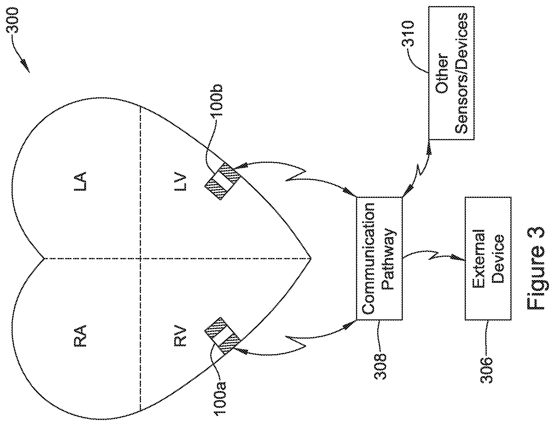
In an illustrative embodiment, the cardiac pacing device may include a leadless cardiac pacemaker (LCP). The leadless cardiac pacemaker may be configured to be implanted in or on a patient's heart and may deliver pacing pulses to the patient's heart. While a leadless cardiac pacemaker is used as an example in this disclosure, it is contemplated that the concepts disclosed herein may be applied to any suitable cardiac pacing device that is configured to delivery cardiac pacing pulses to a patient's heart.
An illustrative leadless cardiac pacemaker may comprise a power supply for providing a power supply voltage, a pair of electrodes for delivering pacing pulses to the heart of the patient, and a controller operably connected to the pair of electrodes and the power supply. The controller may identify a capture threshold and deliver, via the pair of electrodes, a plurality of pacing pulses each having a pace amplitude and a pacing pulse width. The controller may identify a capture threshold by setting the pace amplitude to the power supply voltage and then deliver, via the pair of electrodes, a plurality of pacing pulses having the pace amplitude with different pulse widths to identity the capture pulse width that corresponds to the capture threshold of the heart. Once the capture pulse width has been identified, the controller may deliver via the pair of electrodes a plurality of pacing pulses having the pace amplitude and a pacing pulse width that is greater than the capture pulse width by a pulse width margin. By having the pace amplitude set to the power supply voltage (e.g. battery voltage), little or no power supply energy (e.g. battery energy) is wasted in converting the power supply voltage to the pace amplitude. In some cases, this can significantly increase the useful life expectancy of the leadless cardiac pacemaker.
Additionally, or alternatively to the first illustrative embodiment, the power supply may comprise a battery, and the power supply voltage may comprise a battery voltage provided by the battery.
Additionally, or alternatively, in any of the above embodiments with respect to the first illustrative embodiment, the battery voltage, and thus the pace amplitude, may decay over time.
Additionally, or alternatively, in any of the above embodiments with respect to the first illustrative embodiment, the controller may be configured to identify the capture threshold from time to time.
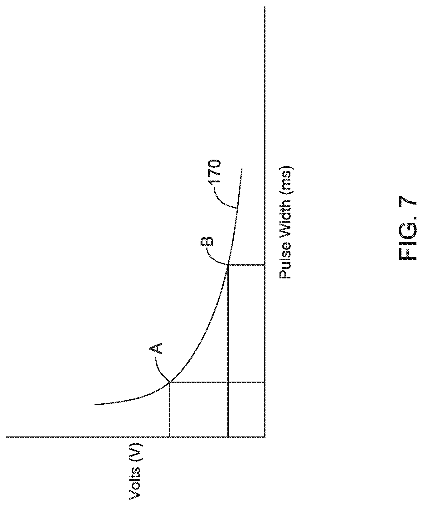
Additionally, or alternatively, in any of the above embodiments with respect to the first illustrative embodiment, the controller may store data representing one or more strength-duration curves, and the controller may be configured to identify a capture threshold strength-duration curve based at least in part on the pace amplitude and the capture pulse width, and the controller may be further configured to identify the pulse width margin by referencing a different one of the strength-duration curves and the pace amplitude.
Additionally, or alternatively, in any of the above embodiments with respect to the first illustrative embodiment, wherein if the power supply voltage changes, and thus the pace amplitude changes, the controller may be configured to automatically adjust the pacing pulse width based at least in part on the different one of the strength-duration curves and the changed pace amplitude, without having to update the capture threshold by delivering via the pair of electrodes a plurality of pacing pulses having the changed pace amplitude and different pulse widths.
Additionally, or alternatively, in any of the above embodiments with respect to the first illustrative embodiment, the controller may be configured to receive the data representing the one or more strength-duration curves from a remote device.
Additionally, or alternatively, in any of the above embodiments with respect to the first illustrative embodiment, the controller may be further configured to receive a user selectable power efficiency value, and wherein the pulse width margin may be based, at least in part, on the user selectable power efficiency value.
Additionally, or alternatively, in any of the above embodiments with respect to the first illustrative embodiment, the user selectable power efficiency value may be received from a remote device.
Additionally, or alternatively, in any of the above embodiments with respect to the first illustrative embodiment, the remote device may comprise a user interface including a display, wherein a user may use the user interface to select the user selectable power efficiency value.
Additionally, or alternatively, in any of the above embodiments with respect to the first illustrative embodiment, the user interface may display a slider that allows the user to select the user selectable power efficiency value from a range of allowable user selectable power efficiency values.
Additionally, or alternatively, in any of the above embodiments with respect to the first illustrative embodiment, the user interface may display a dynamic indicator of an expected life time of the leadless cardiac pacemaker based, at least in part, on the user selectable power efficiency value.
In second illustrative embodiment, a leadless cardiac pacemaker system for delivering pacing pulses to a heart of a patient may comprise a remote device and a leadless cardiac pacemaker that is in communication with the remote device. The remote device may have a user interface with a display for receiving a selection of a user selectable power efficiency value. The leadless cardiac pacemaker may comprise a power supply for providing a power supply voltage, a pair of electrodes for delivering pacing pulses to the heart of the patient, and a controller operably connected to the pair of electrodes and the power supply. The controller identify a pulse width and pulse amplitude combination that corresponds to a capture threshold. The controller may also receive the user selectable power efficiency value from the remote device, and may apply a capture margin to one or more of the pulse width and pulse amplitude that correspond to the capture threshold, resulting in a pacing pulse width and a pacing pulse amplitude. The capture margin may be based at least in part on the user selectable power efficiency value. The controller may then deliver pacing pulses to the heart using the pacing pulse width and the pacing pulse amplitude.
Additionally, or alternatively, the second illustrative embodiment may further comprise the controller being configured to store data representing one or more strength-duration curves, and wherein the controller may be configured to identify the capture margin by indexing the user selectable power efficiency value into the data representing one or more strength-duration curves.
Additionally, or alternatively, to any of the above embodiments with respect to the second illustrative embodiment, wherein the remote device displays on the display a slider that allows the user to select the user selectable power efficiency value from a range of allowable user selectable power efficiency values, and a dynamic indicator of an expected life time of the leadless cardiac pacemaker based, at least in part, on the user selectable power efficiency value.
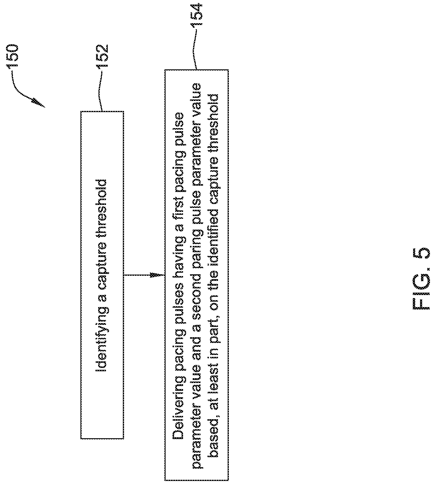
In a third illustrative embodiment, a leadless cardiac pacemaker (LCP) for delivering pacing pulses to a heart of a patient may comprise a pair of electrodes for delivering pacing pulses to the heart of the patient and a controller operably connected to the pair of electrodes. The controller may identify a capture threshold by delivering via the pair of electrodes a plurality of pacing pulses while varying a first pacing pulse parameter value while leaving a second pacing pulse parameter value fixed in order to identity a capture value for the first pacing pulse parameter. Further, the controller may deliver via the pair of electrodes a plurality of pacing pulses that each have the first pacing pulse parameter value at the capture value and the second pacing pulse parameter value at a capture margin above the fixed second pacing pulse parameter value.
Additionally, or alternatively, the third illustrative embodiment may further comprise wherein the first pacing pulse parameter is pulse width and the second pacing pulse parameter is pulse amplitude.
Additionally, or alternatively, to any of the above embodiments with respect to the third illustrative embodiment, the leadless cardiac pacemaker may further comprise a battery that provides a battery voltage, and wherein the fixed second pacing pulse parameter value may be a predetermined fraction of the battery voltage.
Additionally, or alternatively, to any of the above embodiments with respect to the third illustrative embodiment, the second pacing pulse parameter value at the capture margin above the fixed second pacing pulse parameter value may correspond to the battery voltage.
Additionally, or alternatively, to any of the above embodiments with respect to the third illustrative embodiment, the first pacing pulse parameter may be pulse amplitude and the second pacing pulse parameter may be pulse width.
Additionally, or alternatively, to any of the above embodiments with respect to the third illustrative embodiment, the controller may store data representing one or more strength-duration curves, and the controller may be configured to identify the capture margin based at least in part on one or more of the strength-duration curves.
In a fourth illustrative embodiment, a leadless cardiac pacemaker (LCP) for delivering pacing pulses to a heart of a patient may comprise a pair of electrodes for delivering pacing pulses to the heart of the patient and a controller operably connected to the pair of electrodes. The controller identify a pulse width and pulse amplitude combination that corresponds to a capture threshold. The controller may also receive a user selectable power efficiency value from a remote device. The controller may apply a capture margin to one or more of the pulse width and pulse amplitude that correspond to the capture threshold, resulting in a pacing pulse width and a pacing pulse amplitude. The capture margin may be based, at least in part, on the user selectable power efficiency value. The controller may then deliver pacing pulses using the pacing pulse width and the pacing pulse amplitude.
Additionally, or alternatively, the fourth illustrative embodiment may further comprise the controller being configured to store data representing one or more strength-duration curves, and wherein the controller may be configured to identify the capture margin by indexing the user selectable power efficiency value into the data representing one or more strength-duration curves.
Additionally, or alternatively, to any of the above embodiments with respect to the fourth illustrative embodiment, the controller may be configured to receive the data representing one or more strength-duration curves from the remote device.
Additionally, or alternatively, to any of the above embodiments with respect to the fourth illustrative embodiment, the remote device may comprise a user interface including a display, wherein a user may use the user interface to select the user selectable power efficiency value.
Additionally, or alternatively, to any of the above embodiments with respect to the fourth illustrative embodiment, the remote device may display a slider on the display that allows the user select the user selectable power efficiency value from a range of allowable user selectable power efficiency values.
Additionally, or alternatively, to any of the above embodiments with respect to the fourth illustrative embodiment, the remote device may display a dynamic indicator of an expected life time of the leadless cardiac pacemaker based, at least in part, on the user selectable power efficiency value.
Additionally, or alternatively, to any of the above embodiments with respect to the fourth illustrative embodiment, the leadless cardiac pacemaker may further comprise a battery for providing a battery voltage, and wherein the pacing pulse amplitude is set to the battery voltage.
The above summary is not intended to describe each embodiment or every implementation of the present disclosure. Advantages and attainments, together with a more complete understanding of the disclosure, will become apparent and appreciated by referring to the following description and claims taken in conjunction with the accompanying drawings.
BRIEF DESCRIPTION OF THE DRAWINGS
The disclosure may be more completely understood in consideration of the following description of various illustrative embodiments in connection with the accompanying drawings, in which:
FIG. 1 is a schematic block diagram of an illustrative leadless cardiac pacemaker (LCP);
FIG. 2 is a schematic block diagram of another illustrative medical device;
FIG. 3 is a schematic diagram of an exemplary medical system that includes multiple LCPs and/or other devices in communication with one another;
FIG. 4 is a schematic diagram of a system including an LCP and another medical device, in accordance with another embodiment of the present disclosure;
FIG. 5 depicts a schematic flow diagram of an illustrative method for providing pacing stimulation pulses from an LCP;
FIG. 6 depicts a schematic flow diagram of an illustrative method for identifying a capture threshold with an LCP;
FIG. 7 depicts a graph of an illustrative strength-duration curve;
FIG. 8 depicts a graph of a plurality of illustrative strength-duration curves;
FIG. 9 depicts a schematic diagram of an illustrative user interface of a remote device used in conjunction with an LCP;
FIG. 10 depicts a schematic flow diagram of an illustrative method for setting parameters of a pacing stimulation pulse provided by an LCP;
FIG. 11 depicts a schematic flow diagram of another illustrative method for setting parameters of a pacing stimulation pulse provided by an LCP; and
FIG. 12 depicts a schematic flow diagram of an illustrative method for adjusting, over time, parameters of a pacing stimulation pulse provide by an LCP.
While the disclosure is amenable to various modifications and alternative forms, specifics thereof have been shown by way of embodiment in the drawings and will be described in detail. It should be understood, however, that the intention is not to limit aspects of the disclosure to the particular illustrative embodiments described. On the contrary, the intention is to cover all modifications, equivalents, and alternatives falling within the spirit and scope of the disclosure.
DESCRIPTION
The following description should be read with reference to the drawings in which similar elements in different drawings are numbered the same. The description and the drawings, which are not necessarily to scale, depict illustrative embodiments and are not intended to limit the scope of the disclosure.
The present disclosure generally relates to cardiac pacing devices, and more particularly to systems, devices, and methods for setting pacing pulse parameters for such cardiac pacing devices. In an illustrative embodiment, the cardiac pacing device may include a leadless cardiac pacemaker (LCP). The leadless cardiac pacemaker may be configured to be implanted in or on a patient's heart and may deliver pacing pulses to the patient's heart. While a leadless cardiac pacemaker is used as an example in this disclosure, it is contemplated that the concepts disclosed herein may be applied to any suitable cardiac pacing device that is configured to delivery cardiac pacing pulses to a patient's heart.
FIG. 1 is a schematic block diagram of an illustrative leadless cardiac pacemaker (LCP). The illustrative LCP may be implanted on the heart or within a chamber of the heart and may operate to sense physiological signals and parameters and deliver one or more types of electrical stimulation therapy to the heart of the patient. Example electrical stimulation therapy may include bradycardia pacing, rate responsive pacing therapy, cardiac resynchronization therapy (CRT), anti-tachycardia pacing (ATP) therapy and/or the like. The disclosed concepts may be implemented in other IMDs and/or other devices including, but not limited to, pacemakers with leads, defibrillators, and/or other implantable or non-implantable devices.
As can be seen in FIG. 1, LCP 100 may be a compact device with all components housed within LCP 100 or directly on housing 120. In some instances, LCP 100 may include communication module 102, pulse generator module 104, electrical sensing module 106 (e.g., including one or more electrical sensors), mechanical sensing module 108 (e.g., including one or more mechanical sensors), processing module 110 (e.g., a controller including memory and one or more processors), energy storage module 112, and electrodes 114, 114'. Via circuitry, the electrodes 114, 114' may be part of and/or may be in communication with (e.g., operatively coupled to) the communication module 102, the pulse generator module 104, electrical sensing module 106, the mechanical sensing module 108, the processing module 110, and/or the energy storage module 112.
As depicted in FIG. 1, LCP 100 may include electrodes 114, which can be secured relative to housing 120 and electrically exposed to tissue and/or blood surrounding LCP 100. Electrodes 114 may generally conduct electrical signals to and/or from LCP 100 and the surrounding tissue and/or blood. Such electrical signals may include communication signals, electrical stimulation pulses, and intrinsic cardiac electrical signals, to name a few. Intrinsic cardiac electrical signals may include electrical signals generated by the heart and may be represented by an electrocardiogram (ECG). The electrodes may be considered a sensor capable of sensing each of a plurality of heart beats.
Electrodes 114 may include one or more biocompatible conductive materials such as various metals or alloys that are known to be safe for implantation within a human body. In some instances, electrodes 114 may be generally disposed on either end of LCP 100 and may be in electrical communication with one or more of modules 102, 104, 106, 108, and 110. In embodiments where electrodes 114 (e.g., two or more electrodes 114) are secured directly to housing 120, an insulative material may electrically isolate the electrodes 114 from adjacent electrodes, housing 120, and/or other parts of LCP 100. In some instances, some or all of electrodes 114 may be spaced from housing 120 and connected to housing 120 and/or other components of LCP 100 through connecting wires. In such instances, the electrodes 114 may be placed on a tail (not shown) that extends out away from the housing 120.
As shown in FIG. 1, in some embodiments, LCP 100 may include electrodes 114'. Electrodes 114' may be in addition to electrodes 114, or may replace one or more of electrodes 114. Electrodes 114' may be similar to electrodes 114 except that electrodes 114' are disposed on the sides of LCP 100. In some cases, electrodes 114' may increase the number of electrodes by which LCP 100 may deliver communication signals and/or electrical stimulation pulses, and/or may sense intrinsic cardiac electrical signals, communication signals, and/or electrical stimulation pulses.
Electrodes 114 and/or 114' may assume any of a variety of sizes and/or shapes, and may be spaced at any of a variety of spacings. For example, electrodes 114 may have an outer diameter of two to twenty millimeters (mm). In other embodiments, electrodes 114 and/or 114' may have a diameter of two, three, five, seven millimeters (mm), or any other suitable diameter, dimension and/or shape. Example lengths for electrodes 114 and/or 114' may include, for example, one, three, five, ten millimeters (mm), or any other suitable length. As used herein, the length is a dimension of electrodes 114 and/or 114' that extends away from the outer surface of the housing 120. In some instances, at least some of electrodes 114 and/or 114' may be spaced from one another by a distance of twenty, thirty, forty, fifty millimeters (mm), or any other suitable spacing. The electrodes 114 and/or 114' of a single device may have different sizes with respect to each other, and the spacing and/or lengths of the electrodes on the device may or may not be uniform.
In the embodiment shown, communication module 102 may be electrically coupled to electrodes 114 and/or 114' and may be configured to deliver communication pulses to tissues of the patient for communicating with other devices such as sensors, programmers, other medical devices, and/or the like. Communication signals, as used herein, may be any modulated signal that conveys information to another device, either by itself or in conjunction with one or more other modulated signals. In some embodiments, communication signals may be limited to sub-threshold signals that do not result in capture of the heart yet still convey information. The communication signals may be delivered to another device that is located either external or internal to the patient's body. In some instances, the communication may take the form of distinct communication pulses separated by various amounts of time. In some of these cases, the timing between successive pulses may convey information. Communication module 102 may additionally be configured to sense for communication signals delivered by other devices, which may be located external or internal to the patient's body.
Communication module 102 may communicate to help accomplish one or more desired functions. Some example functions include delivering sensed data, using communicated data for determining occurrences of events such as arrhythmias, coordinating delivery of electrical stimulation therapy, and/or other functions. In some cases, LCP 100 may use communication signals to communicate raw information, processed information, messages and/or commands, and/or other data. Raw information may include information such as sensed electrical signals (e.g. a sensed ECG), signals gathered from coupled sensors, and the like. In some embodiments, the processed information may include signals that have been filtered using one or more signal processing techniques. Processed information may also include parameters and/or events that are determined by the LCP 100 and/or another device, such as a determined heart rate, timing of determined heartbeats, timing of other determined events, determinations of threshold crossings, expirations of monitored time periods, accelerometer signals, activity level parameters, blood-oxygen parameters, blood pressure parameters, heart sound parameters, and the like. Messages and/or commands may include instructions or the like directing another device to take action, notifications of imminent actions of the sending device, requests for reading from the receiving device, requests for writing data to the receiving device, information messages, and/or other messages commands.
In at least some embodiments, communication module 102 (or LCP 100) may further include switching circuitry to selectively connect one or more of electrodes 114 and/or 114' to communication module 102 in order to select which electrodes 114 and/or 114' that communication module 102 delivers communication pulses. It is contemplated that communication module 102 may be communicating with other devices via conducted signals, radio frequency (RF) signals, optical signals, acoustic signals, inductive coupling, and/or any other suitable communication methodology.
Where communication module 102 generates electrical communication signals, communication module 102 may include one or more capacitor elements and/or other charge storage devices to aid in generating and delivering communication signals. In the embodiment shown, communication module 102 may use energy stored in energy storage module 112 to generate the communication signals. In at least some examples, communication module 102 may include a switching circuit that is connected to energy storage module 112 and, with the switching circuitry, may connect energy storage module 112 to one or more of electrodes 114/114' to generate the communication signals.
As shown in FIG. 1, a pulse generator module 104 may be electrically connected to one or more of electrodes 114 and/or 114'. Pulse generator module 104 may be configured to generate electrical stimulation pulses and deliver the electrical stimulation pulses to tissues of a patient via one or more of the electrodes 114 and/or 114' in order to effectuate one or more electrical stimulation therapies. Each electrical stimulation pulse may have a pulse amplitude and a pulse width.
Electrical stimulation pulses as used herein are meant to encompass any electrical signals that may be delivered to tissue of a patient for purposes of treatment of any type of disease or abnormality. For example, when used to treat heart disease, the pulse generator module 104 may generate electrical stimulation pacing pulses for capturing the heart of the patient, i.e. causing the heart to contract in response to the delivered electrical stimulation pulse. In some of these cases, LCP 100 may vary the rate at which pulse generator module 104 generates the electrical stimulation pulses, for example in rate adaptive pacing. In other embodiments, the electrical stimulation pulses may include defibrillation/cardioversion pulses for shocking the heart out of fibrillation or into a normal heart rhythm. In yet other embodiments, the electrical stimulation pulses may include anti-tachycardia pacing (ATP) pulses. It should be understood that these are just some examples. When used to treat other ailments, the pulse generator module 104 may generate electrical stimulation pulses suitable for neurostimulation therapy or the like.
Pulse generator module 104 may include one or more capacitor elements and/or other charge storage devices to aid in generating and delivering appropriate electrical stimulation pulses. In at least some embodiments, pulse generator module 104 may use energy stored in energy storage module 112 to generate the electrical stimulation pulses. In some particular embodiments, pulse generator module 104 may include a switching circuit that is connected to energy storage module 112 and may connect energy storage module 112 to one or more of electrodes 114/114' to generate electrical stimulation pulses.
LCP 100 may include an electrical sensing module 106. Electrical sensing module 106 may be configured to sense intrinsic cardiac electrical signals conducted from electrodes 114 and/or 114' to electrical sensing module 106. For example, electrical sensing module 106 may be electrically connected to one or more electrodes 114 and/or 114' and electrical sensing module 106 may be configured to receive cardiac electrical signals conducted through electrodes 114 and/or 114' via a sensor amplifier or the like. In some embodiments, the cardiac electrical signals may represent local information from the chamber in which LCP 100 is implanted. For instance, if LCP 100 is implanted within a ventricle of the heart, cardiac electrical signals sensed by LCP 100 through electrodes 114 and/or 114' may represent ventricular cardiac electrical signals. The electrical sensing module 106 may, in some cases, be configured to identify each of a plurality of heart beats as an intrinsically initiated heart beat or a pace initiated heart beat.
Further, LCP 100 may include a mechanical sensing module 108. Mechanical sensing module 108 may include, or be electrically connected to, various sensors, such as accelerometers, including multi-axis accelerometers such as two- or three-axis accelerometers, gyroscopes, including multi-axis gyroscopes such as two- or three-axis gyroscopes, blood pressure sensors, heart sound sensors, piezoelectric sensors, blood-oxygen sensors, and/or other sensors which measure one or more physiological parameters of the heart and/or patient. Mechanical sensing module 108, when present, may gather signals from the sensors indicative of the various physiological parameters.
Both electrical sensing module 106 and mechanical sensing module 108 may be connected to processing module 110 and may provide signals representative of the sensed cardiac electrical signals and/or physiological signals to processing module 110. Although described with respect to FIG. 1 as separate sensing modules, in some embodiments, electrical sensing module 106 and mechanical sensing module 108 may be combined into a single module. In at least some examples, LCP 100 may only include one of electrical sensing module 106 and mechanical sensing module 108. In some cases, any combination of the processing module 110, electrical sensing module 106, mechanical sensing module 108, communication module 102, pulse generator module 104 and/or energy storage module may be considered a controller of the LCP 100.
Processing module 110 (e.g., a controller) may be configured to direct the operation of LCP 100 and may, in some embodiments, be termed a controller. For example, processing module 110 may be configured to receive cardiac electrical signals from electrical sensing module 106 and/or physiological signals from mechanical sensing module 108. Based on the received signals, processing module 110 may, for example, adjust the rate of pacing based on the activity level of the patient (e.g. rate adaptive pacing). When so provided, processing module 110 may monitor one or more physiological parameters of the patient which may indicate a need for an increased heart rate (e.g. due to increased metabolic demand) and increase the rate at which pulse generator module 104 generates electrical stimulation pulses. Determining an activity level of the patient using a motion sensor (e.g. accelerometer) of the mechanical sensing module 108 of the LCP 100 can be challenging because the motion detected by the motion sensor not only includes the activity level of the patient but also the motion of the beating heart. FIGS. 6-10 describes illustrative methods for aiding in rate responsive pacing using a motion sensor (e.g. accelerometer) in an LCP.
In some cases, the processing module 110 may determine occurrences and types of arrhythmias and other determinations such as whether LCP 100 has become dislodged. Processing module 110 may further receive information from communication module 102. In some embodiments, processing module 110 may additionally use such received information to determine occurrences and types of arrhythmias and/or and other determinations such as whether LCP 100 has become dislodged. In still some additional embodiments, LCP 100 may use the received information instead of the signals received from electrical sensing module 106 and/or mechanical sensing module 108--for instance if the received information is deemed to be more accurate than the signals received from electrical sensing module 106 and/or mechanical sensing module 108 or if electrical sensing module 106 and/or mechanical sensing module 108 have been disabled or omitted from LCP 100.
After determining an occurrence of an arrhythmia, processing module 110 may control pulse generator module 104 to generate electrical stimulation pulses in accordance with one or more electrical stimulation therapies to treat the determined arrhythmia. For example, processing module 110 may control pulse generator module 104 to generate pacing pulses with varying and/or fixed parameters (e.g., one or more of a pulse width, a pulse amplitude and/or other parameters) and in different sequences to effectuate one or more electrical stimulation therapies. As one example, in controlling pulse generator module 104 to deliver bradycardia pacing therapy, processing module 110 may control pulse generator module 104 to deliver pacing pulses having a particular pulse width and pulse amplitude designed to capture the heart of the patient at a regular interval to help prevent a metric of the heart of a patient from falling below a predetermined threshold.
For ATP therapy, processing module 110 may control pulse generator module 104 to deliver pacing pulses at a rate faster than an intrinsic heart rate of a patient in an attempt to force the heart to beat in response to the delivered pacing pulses rather than in response to intrinsic cardiac electrical signals. Once the heart is following the pacing pulses, processing module 110 may control pulse generator module 104 to reduce the rate of delivered pacing pulses down to a safer level. In Cardiac Resynchronization Therapy (CRT), processing module 110 may control pulse generator module 104 to deliver pacing pulses in coordination with another device to cause the heart to contract more efficiently. In cases where pulse generator module 104 is capable of generating defibrillation and/or cardioversion pulses for defibrillation/cardioversion therapy, processing module 110 may control pulse generator module 104 to generate such defibrillation and/or cardioversion pulses. In some cases, processing module 110 may control pulse generator module 104 to generate electrical stimulation pulses to provide electrical stimulation therapies different than those examples described above.
Aside from controlling pulse generator module 104 to generate different types of electrical stimulation pulses and in different sequences, in some embodiments, processing module 110 may also control pulse generator module 104 to generate the various electrical stimulation pulses with varying pulse parameters. For example, each electrical stimulation pulse may have a pulse width and a pulse amplitude. Processing module 110 may control pulse generator module 104 to generate the various electrical stimulation pulses with specific pulse widths and pulse amplitudes. For example, processing module 110 may cause pulse generator module 104 to adjust the pulse width and/or the pulse amplitude of electrical stimulation pulses if the electrical stimulation pulses are not effectively capturing the heart. Such control of the specific parameters of the various electrical stimulation pulses may help LCP 100 provide more effective delivery of electrical stimulation therapy.
In some embodiments, processing module 110 may further control communication module 102 to send information to other devices. For example, processing module 110 may control communication module 102 to generate one or more communication signals for communicating with other devices of a system of devices. For instance, processing module 110 may control communication module 102 to generate communication signals in particular pulse sequences, where the specific sequences convey different information. Communication module 102 may also receive communication signals for potential action by processing module 110.
In further embodiments, processing module 110 may control switching circuitry by which communication module 102 and pulse generator module 104 deliver communication signals and/or electrical stimulation pulses to tissue of the patient. As described above, both communication module 102 and pulse generator module 104 may include circuitry for connecting one or more electrodes 114 and/114' to communication module 102 and/or pulse generator module 104 so those modules may deliver the communication signals and electrical stimulation pulses to tissue of the patient. The specific combination of one or more electrodes by which communication module 102 and/or pulse generator module 104 deliver communication signals and electrical stimulation pulses may influence the reception of communication signals and/or the effectiveness of electrical stimulation pulses. Although it was described that each of communication module 102 and pulse generator module 104 may include switching circuitry, in some embodiments, LCP 100 may have a single switching module connected to the communication module 102, the pulse generator module 104, and electrodes 114 and/or 114'. In such embodiments, processing module 110 may control the switching module to connect modules 102/104 and electrodes 114/114' as appropriate.
In some embodiments, processing module 110 may include a pre-programmed chip, such as a very-large-scale integration (VLSI) chip or an application specific integrated circuit (ASIC). In such embodiments, the chip may be pre-programmed with control logic in order to control the operation of LCP 100. By using a pre-programmed chip, processing module 110 may use less power than other programmable circuits while able to maintain basic functionality, thereby potentially increasing the battery life of LCP 100. In other instances, processing module 110 may include a programmable microprocessor or the like. Such a programmable microprocessor may allow a user to adjust the control logic of LCP 100 after manufacture, thereby allowing for greater flexibility of LCP 100 than when using a pre-programmed chip. In still other embodiments, processing module 110 may not be a single component. For example, processing module 110 may include multiple components positioned at disparate locations within LCP 100 in order to perform the various described functions. For example, certain functions may be performed in one component of processing module 110, while other functions are performed in a separate component of processing module 110.
Processing module 110 may include a memory circuit and processing module 110 may store information on and read information from the memory circuit. In other embodiments, LCP 100 may include a separate memory circuit (not shown) that is in communication with processing module 110, such that processing module 110 may read and write information to and from the separate memory circuit. The memory circuit, whether part of processing module 110 or separate from processing module 110, may be volatile memory, non-volatile memory, or a combination of volatile memory and non-volatile memory.
Energy storage module 112 may be a power supply and provide a power source (e.g., a power supply voltage) to LCP 100 for its operations. In some embodiments, energy storage module 112 may be a non-rechargeable lithium-based battery. In other embodiments, the non-rechargeable battery may be made from other suitable materials. In some embodiments, energy storage module 112 may include a rechargeable battery. In still other embodiments, energy storage module 112 may include other types of energy storage devices such as capacitors or super capacitors.
To implant LCP 100 inside a patient's body, an operator (e.g., a physician, clinician, etc.), may fix LCP 100 to the cardiac tissue of the patient's heart. To facilitate fixation, LCP 100 may include one or more anchors 116. The one or more anchors 116 are shown schematically in FIG. 1. The one or more anchors 116 may include any number of fixation or anchoring mechanisms. For example, one or more anchors 116 may include one or more pins, staples, threads, screws, helix, tines, and/or the like. In some embodiments, although not shown, one or more anchors 116 may include threads on its external surface that may run along at least a partial length of an anchor member. The threads may provide friction between the cardiac tissue and the anchor to help fix the anchor member within the cardiac tissue. In some cases, the one or more anchors 116 may include an anchor member that has a cork-screw shape that can be screwed into the cardiac tissue. In other embodiments, anchor 116 may include other structures such as barbs, spikes, or the like to facilitate engagement with the surrounding cardiac tissue.
In some examples, LCP 100 may be configured to be implanted on a patient's heart or within a chamber of the patient's heart. For instance, LCP 100 may be implanted within any of a left atrium, right atrium, left ventricle, or right ventricle of a patient's heart. By being implanted within a specific chamber, LCP 100 may be able to sense cardiac electrical signals originating or emanating from the specific chamber that other devices may not be able to sense with such resolution. Where LCP 100 is configured to be implanted on a patient's heart, LCP 100 may be configured to be implanted on or adjacent to one of the chambers of the heart, or on or adjacent to a path along which intrinsically generated cardiac electrical signals generally follow. In these examples, LCP 100 may also have an enhanced ability to sense localized intrinsic cardiac electrical signals and deliver localized electrical stimulation therapy. In embodiments where LCP 100 includes an accelerometer, LCP 100 may additionally be able to sense the motion of the cardiac wall to which LCP 100 is attached.
FIG. 2 depicts an embodiment of another device, medical device (MD) 200, which may operate to sense physiological signals and parameters and deliver one or more types of electrical stimulation therapy to tissues of the patient. In the embodiment shown, MD 200 may include a communication module 202, a pulse generator module 204, an electrical sensing module 206, a mechanical sensing module 208, a processing module 210, and an energy storage module 218. Each of modules 202, 204, 206, 208, and 210 may be similar to and/or different than modules 102, 104, 106, 108, and 110 of LCP 100 in one or more manners. Additionally, energy storage module 218 may be similar to and/or different than energy storage module 112 of LCP 100 in one or more manners. However, in some embodiments, MD 200 may have a larger volume within housing 220 than a volume of LCP 100. In such embodiments, MD 200 may include a larger energy storage module 218 and/or a larger processing module 210 capable of handling more complex operations than processing module 110 of LCP 100.
While MD 200 may be another leadless device such as shown in FIG. 1, in some instances MD 200 may include leads, such as leads 212. Leads 212 may include electrical wires that conduct electrical signals between electrodes 214 and one or more modules located within housing 220. In some cases, leads 212 may be connected to and extend away from housing 220 of MD 200. In some embodiments, leads 212 may be implanted on, within, or adjacent to a heart of a patient. Leads 212 may contain one or more electrodes 214 positioned at various locations on leads 212 and various distances from housing 220. Some leads 212 may only include a single electrode 214, while other leads 212 may include multiple electrodes 214. Generally, electrodes 214 may be positioned on leads 212 such that when leads 212 are implanted within the patient, one or more of the electrodes 214 are positioned to perform a desired function. In some cases, the one or more of the electrodes 214 may be in contact with the patient's cardiac tissue. In other cases, the one or more of the electrodes 214 may be positioned subcutaneously but adjacent the patient's heart.
MD 200 may also include one or more electrodes 214 not disposed on a lead 212. For example, one or more electrodes 214 may be connected directly to housing 220.
The electrodes 214 may conduct intrinsically generated electrical cardiac signals to leads 212. Leads 212 may, in turn, conduct the received electrical cardiac signals to one or more of the modules 202, 204, 206, and 208 of MD 200.
In some cases, MD 200 may generate electrical stimulation signals (e.g., having a signal width and a signal amplitude, such as a pulse width and a pulse amplitude), and leads 212 may conduct the generated electrical stimulation signals to electrodes 214. Electrodes 214 may then conduct the electrical stimulation signals to the cardiac tissue of the patient (either directly or indirectly).
Leads 212, in some embodiments, may additionally contain one or more sensors, such as accelerometers, blood pressure sensors, heart sound sensors, blood-oxygen sensors, and/or other sensors which are configured to measure one or more physiological parameters of the heart and/or patient. In such embodiments, mechanical sensing module 208 may be in electrical communication with leads 212 and may receive signals generated from such sensors.
While not required, in some embodiments MD 200 may be an implantable medical device. In such embodiments, housing 220 of MD 200 may be implanted in, for example, a transthoracic region of the patient. Housing 220 may generally include any of a number of known materials that are safe for implantation in a human body and may, when implanted, hermetically seal the various components of MD 200 from fluids and tissues of the patient's body. In such embodiments, leads 212 may be implanted at one or more various locations within the patient, such as within the heart of the patient, adjacent to the heart of the patient, adjacent to the spine of the patient, or any other desired location.
In some embodiments, MD 200 may be an implantable cardiac pacemaker (ICP). In these embodiments, MD 200 may have one or more leads, for example leads 212, which are implanted on or within the patient's heart. The one or more leads 212 may include one or more electrodes 214 that are in contact with cardiac tissue and/or blood of the patient's heart. MD 200 may be configured to sense intrinsically generated cardiac electrical signals and determine, for example, one or more cardiac arrhythmias based on analysis of the sensed signals. MD 200 may be configured to deliver CRT, ATP therapy, bradycardia therapy, and/or other therapy types via leads 212 implanted within the heart. In some embodiments, MD 200 may additionally be configured to provide defibrillation/cardioversion therapy.
In some instances, MD 200 may be an implantable cardioverter-defibrillator (ICD). In such embodiments, MD 200 may include one or more leads implanted within a patient's heart. MD 200 may also be configured to sense electrical cardiac signals, determine occurrences of tachyarrhythmias based on the sensed electrical cardiac signals, and deliver defibrillation and/or cardioversion therapy in response to determining an occurrence of a tachyarrhythmia (for example by delivering defibrillation and/or cardioversion pulses to the heart of the patient). In other embodiments, MD 200 may be a subcutaneous implantable cardioverter-defibrillator (SICD). In embodiments where MD 200 is an SICD, one of leads 212 may be a subcutaneously implanted lead. In at least some embodiments where MD 200 is an SICD, MD 200 may include only a single lead which is implanted subcutaneously but outside of the chest cavity, however this is not required.
In some embodiments, MD 200 may not be an implantable medical device. Rather, MD 200 may be a device external to the patient's body, and electrodes 214 may be skin-electrodes that are placed on a patient's body. In such embodiments, MD 200 may be able to sense surface electrical signals (e.g. electrical cardiac signals that are generated by the heart or electrical signals generated by a device implanted within a patient's body and conducted through the body to the skin). MD 200 may further be configured to deliver various types of electrical stimulation therapy, including, for example, defibrillation therapy via skin-electrodes 214.
FIG. 3 illustrates an embodiment of a medical device system and a communication pathway through which multiple medical devices 100a, 100b, 306, and/or 310 of the medical device system may communicate. In the embodiment shown, medical device system 300 may include a first LCP 100a and a second LCP 100b, external medical device 306, and other sensors/devices 310.
External device 306 may be a device disposed external to a patient's body, as described previously with respect to MD 200. In at least some examples, external device 306 may represent an external support device such as a device programmer, as will be described in more detail below.
Other sensors/devices 310 may be any of the devices described previously with respect to MD 200, such as ICPs, ICDs, and SICDs. Other sensors/devices 310 may also include various diagnostic sensors that gather information about the patient, such as accelerometers, blood pressure sensors, or the like. In some cases, other sensors/devices 310 may include an external programmer device that may be used to program one or more devices of system 300.
Various devices of system 300 may communicate via communication pathway 308. For example, LCPs 100a and/or 100b may sense intrinsic cardiac electrical signals and may communicate such signals to one or more other devices 100a/100b, 306, and 310 of system 300 via communication pathway 308. In one embodiment, one or more of devices 100a/100b may receive such signals and, based on the received signals, determine an occurrence of an arrhythmia. In some cases, device or devices 100a/100b may communicate such determinations to one or more other devices 306 and 310 of system 300. In some cases, one or more of devices 100a/100b, 306, and 310 of system 300 may take action based on the communicated determination of an arrhythmia, such as by delivering a suitable electrical stimulation to the heart of the patient. One or more of devices 100a/100b, 306, and 310 of system 300 may additionally communicate command or response messages via communication pathway 308. The command messages may cause a receiving device to take a particular action whereas response messages may include requested information or a confirmation that a receiving device did, in fact, receive a communicated message or data.
It is contemplated that the various devices of system 300 may communicate via pathway 308 using RF signals, inductive coupling, optical signals, acoustic signals, or any other signals suitable for communication. Additionally, in at least some embodiments, the various devices of system 300 may communicate via pathway 308 using multiple signal types. For instance, other sensors/device 310 may communicate with external device 306 using a first signal type (e.g. RF communication) but communicate with LCPs 100a/100b using a second signal type (e.g. conducted communication). Further, in some embodiments, communication between devices may be limited. For instance, as described above, in some embodiments, LCPs 100a/100b may communicate with external device 306 only through other sensors/devices 310, where LCPs 100a/100b may send signals to other sensors/devices 310, and other sensors/devices 310 relay the received signals to external device 306.
In some cases, the various devices of system 300 may communicate via pathway 308 using conducted communication signals. Accordingly, devices of system 300 may have components that allow for such conducted communication. For instance, the devices of system 300 may be configured to transmit conducted communication signals (e.g. a voltage and/or current waveform punctuated with current and/or voltage pulses, referred herein as electrical communication pulses) into the patient's body via one or more electrodes of a transmitting device, and may receive the conducted communication signals via one or more electrodes of a receiving device. The patient's body may "conduct" the conducted communication signals from the one or more electrodes of the transmitting device to the electrodes of the receiving device in the system 300. In such embodiments, the delivered conducted communication signals may differ from pacing pulses, defibrillation and/or cardioversion pulses, or other electrical stimulation therapy signals. For example, the devices of system 300 may deliver electrical communication pulses at an amplitude/pulse width that is sub-threshold. That is, the communication pulses have an amplitude/pulse width designed to not capture the heart. In some cases, the amplitude/pulse width of the delivered electrical communication pulses may be above the capture threshold of the heart, but may be delivered during a refractory period of the heart and/or may be incorporated in or modulated onto a pacing pulse, if desired.
Additionally, unlike normal electrical stimulation therapy pulses, the electrical communication pulses may be delivered in specific sequences which convey information to receiving devices. For instance, delivered electrical communication pulses may be modulated in any suitable manner to encode communicated information. In some cases, the communication pulses may be pulse width modulated and/or amplitude modulated. Alternatively, or in addition, the time between pulses may be modulated to encode desired information. In some cases, a predefined sequence of communication pulses may represent a corresponding symbol (e.g. a logic "1" symbol, a logic "0" symbol, an ATP therapy trigger symbol, etc.). In some cases, conducted communication pulses may be voltage pulses, current pulses, biphasic voltage pulses, biphasic current pulses, or any other suitable electrical pulse as desired.
FIG. 4 depicts an illustrative medical device system 400. For example, system 400 may include multiple devices that are implanted within a patient and are configured to sense physiological signals, determine occurrences of cardiac arrhythmias, and deliver electrical stimulation to treat detected cardiac arrhythmias. In some embodiments, the devices of system 400 may be configured to determine occurrences of dislodgment of one or more devices of system 400. In FIG. 4, an LCP 100 is shown fixed to the interior of the right ventricle of the heart 410, and a pulse generator 406 is shown coupled to a lead 412 having one or more electrodes 408a-408c. In some cases, pulse generator 406 may be part of a subcutaneous implantable cardioverter-defibrillator (SICD), and the one or more electrodes 408a-408c may be positioned subcutaneously adjacent the heart. LCP 100 may communicate with the SICD, such as via communication pathway 308. The locations of LCP 100, pulse generator 406, lead 412, and electrodes 408a-c depicted in FIG. 4 are just exemplary. In other embodiments of system 400, LCP 100 may be positioned in the left ventricle, right atrium, or left atrium of the heart, as desired. In still other embodiments, LCP 100 may be implanted externally adjacent to heart 410 or even remote from heart 410.
Medical device system 400 may also include external support device 420. External support device 420 can be used to perform functions such as device identification, device programming and/or transfer of real-time and/or stored data between devices using one or more of the communication techniques described herein, or other functions involving communication with one or more devices of system 400. As one example, communication between external support device 420 and pulse generator 406 can be performed via a wireless mode, and communication between pulse generator 406 and LCP 100 can be performed via a conducted communication mode. In some embodiments, communication between LCP 100 and external support device 420 is accomplished by sending communication information through pulse generator 406. However, in other embodiments, communication between the LCP 100 and external support device 420 may be via a communication module.
FIG. 4 only illustrates one example embodiment of a medical device system that may be configured to operate according to techniques disclosed herein. Other example medical device systems may include additional or different medical devices and/or configurations. For instance, other medical device systems that are suitable to operate according to techniques disclosed herein may include additional LCPs implanted within the heart. Another example medical device system may include a plurality of LCPs with or without other devices such as pulse generator 406, with at least one LCP capable of delivering defibrillation therapy. Still another example may include one or more LCPs implanted along with a transvenous pacemaker and with or without an implanted SICD. In yet other embodiments, the configuration or placement of the medical devices, leads, and/or electrodes may be different from those depicted in FIG. 4. Accordingly, it should be recognized that numerous other medical device systems, different from system 400 depicted in FIG. 4, may be operated in accordance with techniques disclosed herein. As such, the embodiment shown in FIG. 4 should not be viewed as limiting in any way.
Implantable medical devices, such as LCP 100, often have an energy storage module 112 with a limited power capacity. The power capacity of the energy storage module 112 often dictates the useful life expectancy of the implantable medical device. In many cases, it is the pacing stimulation pulses delivered by the implantable medical device that dominate the energy consumption from the energy storage module 112. As such, increasing the energy efficiency of the pacing stimulation pulses can increase the longevity of the energy storage module 112 and thus the implantable medical device, and/or may reduce the size (e.g., physical size and/or storage size) of the energy storage module 112 and thus reduce the size of the implantable medical device.
In some cases, implantable medical device may include a linear power regulator to convert the battery voltage produced by the energy storage module 112 (e.g. battery voltage) to another voltage used by the implantable medical device. For example, in some cases, an implantable medical device may have a battery voltage of 5 volts, but may deliver pacing pulses at a pacing amplitude of 2.5 volts. A linear power regulator may convert the 5 Volt battery voltage to the 2.5 volts uses in generating the pacing pulses. For a linear power regulator, the maximum efficiency of this conversion may be the ratio of the output voltage (2.5V) to the input voltage (5V), or in this case 50%. The conversion efficiency of other circuits for converting a battery voltage to another voltage are also less than idea. To overcome this inefficiency, it is contemplated that the pacing pulse amplitude may be set at or near the battery voltage, and the pulse width may be adjusted until pacing pulses are produced that reliably capture the heart.
FIG. 5 depicts a schematic flow diagram for an illustrative method 150 of pacing a heart with an LCP, such as LCP 100 of FIG. 1. The illustrative method 150 includes identifying 152 a capture threshold for a pacing stimulation pulse delivered to a patient's heart, such as through two or more of the electrodes 114 and/or 114' of the LCP 100. The "capture threshold" may be identified by varying the pulse amplitude and/or pulse width until a stimulation pulse is found that just captures the heart.
The method 150 may further include delivering 154 a pacing stimulation pulse having a value for a first pacing pulse parameter (e.g., a pulse amplitude, a pulse width, and/or other parameter) and a value for a second pacing pulse parameter (e.g., a pulse amplitude, a pulse width, and/or other parameter) that are based, at least in part, on the identified capture threshold. In one example, the delivered pacing stimulation pulse may have a first pacing pulse parameter (pulse amplitude) and a second pacing pulse parameter (pulse width) that correspond to the capture threshold. In another example, the delivered pacing stimulation pulse may have a first pacing pulse parameter (pulse amplitude) and/or a second pacing pulse parameter (pulse width) that is a multiple of the parameters that correspond to the capture threshold, thereby providing a capture margin beyond the identified capture threshold. In another example, the delivered pacing stimulation pulse may have a first pacing pulse parameter (pulse amplitude) and a second pacing pulse parameter (pulse width) that is derived from a strength-duration curve that provides a capture margin beyond the identified capture threshold. These are just examples. In some cases, the pacing stimulation pulse may be delivered to a patient's heart from LCP 100 through the electrodes 114 and/or 144' in response to a determination by the processing module 110 that a pacing stimulation pulse is needed or is to be initiated.
FIG. 6 depicts a schematic flow diagram of an illustrative method 160 for identifying capture threshold values. The illustrative method 160 includes setting 162 a first pacing pulse parameter to a fixed value (e.g., a fixed first value). In one example, the first pacing pulse parameter may be a pulse amplitude of the pacing stimulation pulse, and in some cases the fixed value may set at the battery voltage of the energy storage module 112 of LCP 100. In some cases, the first fixed value may be considered "fixed" for at least a period of time.
Once the first pacing pulse parameter is set to the fixed value, the illustrative method 160 delivers 164 one or more pacing stimulation pulses to a patient's heart. In one example, the pacing stimulation pulses may be initiated by the processing module 110 of LCP 100, generated by the pulse generator module 104, and delivered through one or more of the electrodes 114 and/or 114'. However, other pacing stimulation pulse delivery techniques may be utilized. While maintaining the first pacing pulse parameter at the fixed value, the illustrative method 160 may vary 166 the value of a second pacing pulse parameter (e.g. pulse width). In some cases, the value of the second pacing pulse parameter may be varied over different pacing pulses during a capture threshold test until the patient's heart is captured (e.g., as identified by the electrical sensing module 106 and/or the processing module 110). The value of the second pacing pulse parameter may be varied in any manner including, but not limited to, varying the value of the second pacing pulse parameter on sequential pacing stimulation pulses of a group of pacing stimulation pulses, providing a first group of pacing stimulation pulses with a first value of the second pacing pulse parameter and then provide a next group (e.g., second or further group) of pacing stimulation pulses with a second value of the second pacing pulse parameter, and/or in any other suitable manner. Alternatively, the first pacing pulse parameter may be a pulse width of the pacing stimulation pulse and the pulse amplitude may be varied for two or more pacing stimulation pulses.
Once a capture threshold is identified from delivering pacing stimulation pulses, the illustrative method 160 may include identifying 168 a capture value for the second pacing pulse parameter. The capture value may correspond to the value of the second pacing pulse parameter used when the capture threshold is identified. In one example, where the second pacing pulse parameter is a pulse width, a value (e.g., a length of time) of the pulse width may be varied during the delivery of the one or more pacing stimulation pulses to identify a capture pulse width that corresponds to the capture threshold for the set fixed value of the first pacing pulse parameter (e.g., a set pulse amplitude). After identifying the capture threshold (e.g., the capture pulse width and the set pulse amplitude, or other values of the first and second pacing pulse parameters), the LCP 100 may deliver, via electrodes 114 and/or 114', one or more pacing pulses having values for the first pacing pulse parameter and the second pacing pulse parameter that is equal to or greater than the fixed value of the first pacing pulse parameter and/or equal to or greater than the capture value of the second pacing pulse parameter (e.g., see the delivering step 154 of method 150 in FIG. 5).
In some cases, the processing module 110 of the LCP 100 may initiate identifying and/or may identify a capture threshold for a pacing pulse stimulation. In some case, the processing module 110 may initiate identifying and/or may identify a capture threshold at predetermined time intervals, after an identified event, after a patient changes position or posture, after a patient changes an activity level, and/or at one or more other times.
FIG. 7 depicts an illustrative strength-duration curve 170 with pulse duration (e.g., milliseconds (ms)) along the X-axis and pulse amplitude along the Y-axis. For all combinations of X values (e.g., pulse duration) and Y values (e.g., pulse amplitude) of a pacing stimulation pulse that fall on a particular strength-duration curve, a same or substantially the same stimulation effectiveness is provided by the pacing stimulation pulse to a patient's heart. As shown in the example of FIG. 7, a pacing stimulation pulse at point A on the strength-duration curve 170 has a higher value for the first pacing pulse parameter (e.g., pace amplitude) and a lower value for the second pacing pulse parameter (e.g., pulse width) relative to the value of the first pacing pulse parameter and the value of the second pacing pulse parameter for a pacing stimulation pulse at point B. However, each of the pacing pulse parameter sets at point A and point B may provide the same or substantially the same stimulation effectiveness to the patient's heart (e.g. both will capture the heart similarly).
In some cases, one or more strength duration curves may be saved in a memory of the LCP 100 (e.g., memory of the processing module 110 and/or other memory) and/or in memory with which the LCP 100 may be in communication. In some cases, a family of strength-duration curves may be stored. The family of strength-duration curves may be based on the particular patient at hand, or on a population of patients. An illustrative family of strength-duration curves are shown in FIG. 8. The LCP 100 may use an identified capture threshold for the particular patient, as determined through a capture threshold test performed by the implanted LCP 100, to identify a particular one of the family of strength-duration curve that corresponds to the capture threshold for the particular patient. Once identified, the LCP may fix the pulse amplitude (e.g. at the battery voltage) and then pick the "nth" strength-duration curve to the right to identify the pulse width that provides an appropriate capture margin. The LCP may then pace the patient's heart using pacing pulses that have the fixed pulse amplitude (e.g. the battery voltage) and the pulse width that provides the appropriate capture margin.
In some cases, the LCP 100 may use one or more strength duration curves to adjust a value of a first pacing pulse parameter and/or a value of a second pacing pulse parameter while maintaining a stimulation effectiveness of the pacing pulses. In the example of FIG. 7, point A may represent a pacing stimulation pulse at which a capture was identified and thus, the stimulation effectiveness at point A, and along the strength-duration curve 170, may be considered the capture threshold. In some cases, the processing module 110 may determine that it is more power efficient to operate at a lower value of the first pacing pulse parameter and adjust the value of the second pacing pulse parameter to a value associated with the lower value of the first pacing pulse parameter along the strength-duration curve 170 (e.g., at point B on the strength-duration curve 170). This may result in more efficiently provide pacing stimulation pulses while maintaining a stimulation effectiveness applied to the patient's heart by the pacing stimulation pulses. In some cases, a capture margin may be applied to the first pacing pulse parameter and/or the second pacing pulse parameter, as desired.
In one example, the processing module 110 may set (e.g., fix) the value of the first pacing pulse parameter to be equal to a power supply voltage provide by the energy storage module 112, and may identify the pulse width at the capture threshold, and thus the strength-duration curve 170 that is associated with the capture threshold (e.g., where the strength-duration curve may be stored in memory associated with the LCP 100). When the energy storage module 112 is a battery and the power supply voltage is the voltage of the battery, the voltage of the battery may decay over time. As a result, the value of the first pacing pulse parameter may also decay over time in proportion to the battery voltage decay. To account for the potential decay of the value of the first pacing pulse parameter, the processing module 110 may track the battery voltage, adjust the value of the first pacing pulse parameter as the battery voltage changes over time, and adjust a value of the second pacing pulse parameter (e.g. pacing pulse width) along the identified strength-duration curve 170 to points that correspond to the adjusted value of the first pacing pulse parameter to provide pacing stimulation pulse that provide the same or similar stimulation effectiveness. In some cases, a capture margin is applied to the second pacing pulse parameter to help ensure reliable capture of the heart going forward.
FIG. 8 depicts a plurality of strength-duration curves. As referred to above a family of strength-duration curves (e.g., the five strength-duration curves 170, 172, 174, 176, 178 depicted in FIG. 8) may be saved in a memory of the LCP 100 (e.g., memory of the processing module 110 and/or other memory) and/or in memory with which the LCP 100 may be in communication. In some cases, the LCP 100 storing the family of strength-duration curves may facilitate the LCP 100 (e.g., the processing module 110) provide pacing stimulation pulses in accordance with a received or identified capture margin. For example, a capture margin may correspond to a percentage offset of the capture threshold. When so provided, the capture margin may be higher when the capture threshold is higher. In another example, the capture margin may correspond to a fixed offset from the capture threshold. In yet another example, the capture margin may be selected by moving "n" strength-duration curve to the right in FIG. 8, and then use the pulse amplitude and/or pulse width dictated by that strength-duration curve. These are just some examples.
In FIG. 8, the strength-duration curve 170 may be considered to be associated with the capture threshold of the patient. That is the capture threshold identified via a capture threshold test falls along strength-duration curve 170, such as at point A. The pacing stimulation pulses associated with each of the strength-duration curves 172, 174, 176, and 178 to the right of the strength-duration curve 170 may provide a capture margin over the pacing stimulation pulses provided in accordance with the strength-duration curve 170. In one example, the pacing stimulation pulses associated with each sequential strength duration curve 172, 124, 126 and 178 may provide one percent (1%) more, two percent (2%) more, three percent (3%) more, five percent (5%) more, ten percent (10%) more, twenty percent (20%) more, or any other suitable amount more pulse width than the pulse width provided by the pacing stimulation pulse associated with a strength duration curve 170. In another example, the pacing stimulation pulses associated with each sequential strength duration curve 172, 124, 126 and 178 may provide one percent (1%) more, two percent (2%) more, three percent (3%) more, five percent (5%) more, ten percent (10%) more, twenty percent (20%) more, or any other suitable amount more pulse amplitude than the pulse amplitude provided by the pacing stimulation pulse associated with a strength duration curve 170. In yet another example, the pacing stimulation pulses associated with each sequential strength-duration curve 172, 124, 126 and 178 may consume one percent (1%) more, two percent (2%) more, three percent (3%) more, five percent (5%) more, ten percent (10%) more, twenty percent (20%) more, or any other suitable amount of more power from the energy storage module 112 than the amount of power drawn by the pacing stimulation pulses associated with a strength duration curve 170. In another example, the pacing stimulation pulses associated with each sequential strength duration curve 172, 124, 126 and 178 may provide one percent (1%) more, two percent (2%) more, three percent (3%) more, five percent (5%) more, ten percent (10%) more, twenty percent (20%) more, or any other suitable amount more stimulation amount than the stimulation amount provided by the pacing stimulation pulse associated with a strength duration curve 170. These are just examples. Moreover, rather than a linear progression from one strength-duration curve 172, 124, 126 and 178 to the next, it is contemplated that there may be a non-linear progression such as a step-wise progression, an exponential progression, a logarithmic progression, and/or any other suitable progression as desired.
In some cases, the processing module 110 of the LCP 100 may select a stored strength-duration curve based, at least in part, on an identified capture threshold and a predetermined capture margin and/or a capture margin received from a physician. In some cases, a capture threshold determined by a capture threshold test performed by the LCP 100 may not align directly with a stored strength-duration curve. In such cases, processing module 110 may select (e.g., automatically or upon selection and/or approval by a physician) a strength-duration curve that is closest to the capture threshold. Once the processing module 110 of the LCP has selected a strength-duration curve 170 associated with the capture threshold, the processing module 110 may identify a further strength-duration curve associated with the predetermined or received capture margin. For example, a capture margin may correspond to the "nth" strength-duration curve to the right of the strength-duration curve that is closest to the capture threshold.
In an example, the LCP 100 may fix the pulse amplitude (e.g. at the battery voltage) and then perform a capture threshold test by varying pulse amplitude. In FIG. 8, this may correspond to point A along the strength-duration curve 170. The LCP 100 may then pick the "nth" strength-duration curve to the right to identify the pulse width that provides an appropriate capture margin. For example, the LCP 100 may pick the first (e.g. n=1) strength-duration curve to the right 172, and for the fixed pulse amplitude find a new pulse width at operating point C. Operating point C provides a desired pacing margin to help ensure reliable pacing going forward.
In another example, the LCP 100 may fix the pulse amplitude (e.g. at the battery voltage) and then perform a capture threshold test by varying pulse amplitude. In FIG. 8, this may correspond to point B along the strength-duration curve 170. The LCP 100 may then pick the "nth" strength-duration curve to the right to identify the pulse width that provides an appropriate capture margin. For example, the LCP 100 may pick the first (e.g. n=1) strength-duration curve to the right 172, and for the fixed pulse amplitude find a new pulse width at operating point D. Operating point D provides a desired pacing margin to help ensure reliable pacing going forward. As shown in FIG. 8, points A and C have the same pulse amplitude, but have different pulse widths to provide the desired capture margin. Likewise, points B and D have the same pulse amplitude, but have different pulse widths to provide the desired capture margin.
In some cased, and once a strength-duration curve has been selected to provide the desired capture margin, and the pacing amplitude drops over time due to a decreasing battery voltage, the processing module 110 may automatically adjust the pacing pulse width of the pacing stimulation pulses in accordance with the selected strength-duration curve. For example, assume the strength-duration curve 172 of FIG. 8 has been selected to provide the desired capture margin, and the initial pacing amplitude corresponded to point C. The processing module 110 may set the pacing pulse width to correspond to operating point C. As the batter drains over time, the pacing amplitude may drop down to point D. The processing module 110 may automatically drop the pacing pulse width over time along strength-duration curve 172 to operating point D, all along providing a desired capture margin and possibly without having to update the capture threshold.
In some cases, a physician may select a desired capture margin to use. A physician may take one or more factors into consideration when adjusting or selecting a capture margin for an LCP 100. Some factors may include, but are not limited to, an absolute pulse amplitude margin (e.g. 2 volts), a relative pulse amplitude margin (+10%), an absolute pulse width margin (e.g. 50 ms), a relative pulse width margin (+10%), a pacing pulse energy margin (e.g. 10% more energy than at the capture threshold), a margin based on a desired lifetime of the LCP 100 and/or any other suitable margin. It is contemplated that a physician may select the capture margin using a user interface, such as user interface 180 shown in FIG. 9.
In one example, the capture margin may be related to the estimated life (e.g., duration) of the LCP 100. As such, a physician may be given an opportunity to select a Power Efficiency Value from a user interface 180 such as shown in FIG. 9. Based on the Power Efficiency Value selected, an appropriate capture margin may be selected at which to use when providing pacing stimulation pulses. In some cases, a pulse amplitude/pulse width combination may be selected to achieve the selected Power Efficiency Value. In some cases, the particular pulse amplitude and/or pulse width may not be reported to the physician. Instead, the pulse amplitude and/or pulse width may be optimized to reduce the overall power consumption of the LCP 100. For example, to minimize the energy consumed in converting a battery voltage to a different pacing pulse amplitude, the pulse amplitude may be set equal to the battery voltage, and the pulse width may be adjusted to achieve the desired capture margin. The capture margin may be dependent on the Power Efficiency Value selected by the physician.
The user interface 180 may be part of a remote device (e.g., external device 360, external support device 420, and/or a different remote device) that may be in communication with the LCP 100 over a network (e.g., communication pathway 308). Alternatively, or in addition, the user interface 180 may be located in or on a personal computer, a laptop computer, a tablet computer, a mobile phone, a smart phone, and/or other computing device, wherein the selected value may be communicated to the LCP 100.
As can be seen, the user interface 180 may include a Power Efficiency Value selector 182. In the example shown, the Power Efficiency Value selector 182 may be a slide bar that may be slid between a minimum (min) value and a maximum (max) value. Additionally or alternatively, the Power Efficiency Value selector 182 may allow a user to select a specific value in a range of values, and the values may be for a generic range (e.g., 0-10, 0-100, 14-29, and so on), may be associated with an estimated life of the LCP 100 (e.g., in years), may be associated with a capture margin percent over a capture threshold, and/or may be associated with one or more other values. In some cases, the user interface 180 may include an indicator 184 (e.g., a dynamic indicator) of an estimated life for the LCP 100 based on (e.g., that changes with) a selected Power Efficiency Value. In one example, as a higher capture margin is selected via the Power Efficiency Value selector 182, the shorter the duration of the expected life remaining for the LCP 100.
FIG. 10 is a flow diagram of an illustrative method 500 of setting values for parameters of a pacing stimulation pulse that may be related to an identified capture threshold. The method 500 may include the processing module 110 of an LCP 100 setting 502 a pace amplitude (note, pulse amplitude and pace amplitude may be used interchangeably herein) to a fixed pace amplitude. In one example, the fixed pace amplitude may be a power supply voltage (e.g. battery voltage) of an energy storage module 112, a percentage of the power supply voltage, and/or other voltage. Then, while providing pacing stimulation pulses to a patient via the electrodes 114, 114', the method 500 may include adjusting 504 a pulse width of the pacing stimulation pulses until a capture threshold has been identified, and then selecting 506 a threshold strength duration curve (e.g., curve 170 in FIGS. 7 and 8) corresponding to the capture threshold.
As an alternative to setting the pace amplitude of the pacing stimulation pulses to a fixed pace amplitude and adjusting the pulse width of the pacing stimulation pulses to identify a capture threshold as in steps 502 and 504, the processing module 110 may be configured to set the pulse width of the pacing stimulation pulses to a fixed pulse width and adjust the pace amplitude of the pacing stimulation pulses to identify a capture threshold.
At step 508, the processing module 110 may determine whether a capture margin has been received, and if no capture margin has been received, the processing module 110 may set 510 electrical stimulation pulse settings based, at least in part, on the strength-duration curve corresponding to the capture threshold and a default capture margin if present. This may include automatically selecting a capture margin strength duration curve based, at least in part, on the default capture margin and the strength-duration curve corresponding to the identified capture threshold. Then, the processing module 110 may set 510 electrical stimulation pulse settings based, at least in part, on the selected margin strength-duration curve.
In instances when a capture margin has been received, such as from a physician, the processing module 110 may set electrical stimulation pulse settings based, at least in part, on the strength-duration curve corresponding to the capture threshold and the received capture margin. This may include automatically selecting 512 a capture margin strength duration curve based, at least in part, on the received capture margin and the strength-duration curve corresponding to the identified capture threshold. Then, the processing module 110 may set 514 electrical stimulation pulse settings based, at least in part, on the selected margin strength-duration curve.
FIG. 11 is a flow diagram of an illustrative method 600 of setting values for parameters of a pacing stimulation pulse that may be related to a capture threshold. In the illustrative method 600, the processing module 110 may identify 602 a fixed pace amplitude. In one example, the fixed pace amplitude may be a power supply voltage (e.g. battery voltage) of an energy storage module 112, a percentage of the power supply voltage, and/or other voltage. The processing module 110 may set 604 a pace amplitude of a pacing stimulation pulse to a fraction of the identified fixed pace. In one example, the set pace amplitude may be a fraction of a power supply voltage of the energy storage module 112, and may be set based on a desired capture margin. In one example, if the capture margin is 2 times the capture threshold, the fraction may be set to one half and the set pacing amplitude will be one half of the identified fixed pace amplitude. Once the pace amplitude has been set and the while the LCP 100 may be applying pacing stimulation pulses to a patient, the processing module 110 may adjust 606 a pulse width of the pacing stimulation pulses until a capture threshold is identified. Once the capture threshold has been identified and an associated pulse width at the set pulse amplitude of the pacing stimulation pulse is stored, the processing module 110 may re-set 608 the pacing stimulation pulses to have the identified fixed pace amplitude and set 610 the pacing stimulation pulses to have the pulse width corresponding to that identified at the capture threshold. The resulting pacing stimulation pulse may have parameter values that result in the desired capture margin (2.times.).
In some cases, the processing module 110 may identify a strength-duration curve associated with the set pacing pulse parameter values that correspond to the capture threshold and the desired capture margin (e.g., the processing module 110 may select a strength-duration curve that may be the closest curve to the set pacing pulse parameter values) and adjust the pulse width over time as the pace amplitude changes over time due to power supply voltage decay or the like.
FIG. 12 is a flow diagram of an illustrative method 700 of adjusting, over time, a set pace amplitude for pacing stimulation pulses. The illustrative method 700 may be implemented by the processing module 110 of the LCP 100 at initial set up of the device before and/or after implantation, at pre-set intervals after initial set up of the implanted device, continuously in real-time after initial set up of the implanted device, and/or at any other time. The illustrative method 700 may include the processing module 110 determining 702 a fixed pace amplitude at which to set the pace amplitude of a pacing stimulation pulse, and determining 704 a pulse width at the fixed pace amplitude. As discussed herein, in one example, the fixed pace amplitude may correspond to the power supply voltage (e.g. battery voltage) of the energy storage module 112, a percentage of the power supply voltage, and/or other voltage as desired. The pulse width at the fixed pace amplitude may be determined by identifying a pulse width associated with (e.g., lined up with) the fixed pace amplitude along a strength-duration curve (e.g., strength-duration curves 170, 172, 174, 176, 178 in FIG. 8 or other strength-duration curves). Once the fixed pace amplitude of the pacing stimulation pulses is determined 702 and an associated pulse width for the pacing simulation pulses is determined 704, the processing module 110 may adjust 706 the electrical stimulation pulse settings to the determined fixed pace amplitude and the determined pulse width.
Over time (e.g., at pre-determined time intervals or in real time), the processing module 110 may determine 708 if a bases for determining the fixed pace amplitude has changed. In one example, if the fixed pace amplitude is set to be equal to a power supply voltage from the energy storage module 112, the processing module 110 may determine if the power supply voltage from the energy storage module 112 has changed by a predetermined amount since the fixed pace amplitude was previously determined. This determination may be made continuously at pre-determined times and/or in real-time. If the processing module 110 determines the bases for determining the fixed pace amplitude has not changed, then the processing module 110 may maintain 710 the current pacing stimulation pulse settings and continuously determine 708 if a bases for determining the fixed pace amplitude has changed. If the processing module 110 determines the bases for determining the fixed pace amplitude has changed, then the processing module 110 may return to determining 702 a fixed pace amplitude at which to set the pace amplitude of the pacing stimulation pulses and the method 700 may be repeated.
Those skilled in the art will recognize that the present disclosure may be manifested in a variety of forms other than the specific embodiments described and contemplated herein. For instance, as described herein, various embodiments include one or more modules described as performing various functions. However, other embodiments may include additional modules that split the described functions up over more modules than that described herein. Additionally, other embodiments may consolidate the described functions into fewer modules.
Although various features may have been described with respect to less than all embodiments, this disclosure contemplates that those features may be included on any embodiment. Further, although the embodiments described herein may have omitted some combinations of the various described features, this disclosure contemplates embodiments that include any combination of each described feature. Accordingly, departure in form and detail may be made without departing from the scope and spirit of the present disclosure as described in the appended claims.
* * * * *
D00000
D00001
D00002
D00003
D00004
D00005
D00006
D00007
D00008
D00009
D00010
D00011
D00012
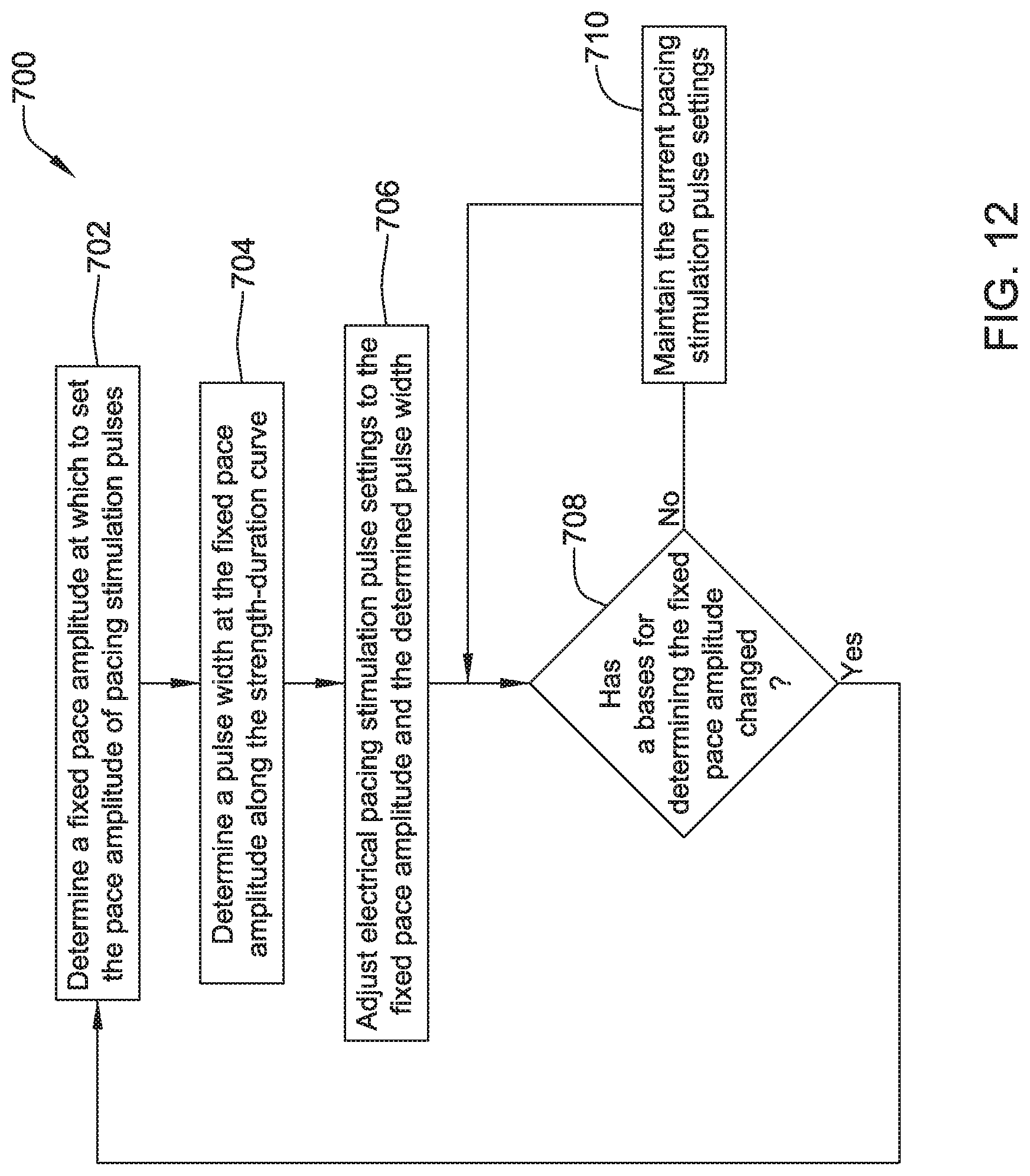
XML
uspto.report is an independent third-party trademark research tool that is not affiliated, endorsed, or sponsored by the United States Patent and Trademark Office (USPTO) or any other governmental organization. The information provided by uspto.report is based on publicly available data at the time of writing and is intended for informational purposes only.
While we strive to provide accurate and up-to-date information, we do not guarantee the accuracy, completeness, reliability, or suitability of the information displayed on this site. The use of this site is at your own risk. Any reliance you place on such information is therefore strictly at your own risk.
All official trademark data, including owner information, should be verified by visiting the official USPTO website at www.uspto.gov. This site is not intended to replace professional legal advice and should not be used as a substitute for consulting with a legal professional who is knowledgeable about trademark law.