Electrosurgical forceps for video assisted thoracoscopic surgery and other surgical procedures
Frushour , et al.
U.S. patent number 10,631,887 [Application Number 15/671,200] was granted by the patent office on 2020-04-28 for electrosurgical forceps for video assisted thoracoscopic surgery and other surgical procedures. This patent grant is currently assigned to Covidien LP. The grantee listed for this patent is COVIDIEN LP. Invention is credited to Scott E. M. Frushour, Eric R. Larson.


| United States Patent | 10,631,887 |
| Frushour , et al. | April 28, 2020 |
Electrosurgical forceps for video assisted thoracoscopic surgery and other surgical procedures
Abstract
A surgical instrument includes a shaft defining an axis, an end effector coupled to a distal portion thereof, a fixed handle coupled to a proximal portion thereof, a drive bar, a movable handle, and a linkage. The drive bar is disposed within the shaft and operably coupled to the end effector. The movable handle is movable relative to the fixed handle between open and closed positions and is coupled to the drive bar via a first pin on the axis. The linkage includes a first end portion coupled to the movable handle via a second pin and a second end portion coupled to the shaft via a third pin on the axis. In the closed position of the movable handle, the second pin is disposed in a near-over-center position relative to the axis to reduce a force necessary to maintain the movable handle in the closed position.
| Inventors: | Frushour; Scott E. M. (Boulder, CO), Larson; Eric R. (Boulder, CO) | ||||||||||
|---|---|---|---|---|---|---|---|---|---|---|---|
| Applicant: |
|
||||||||||
| Assignee: | Covidien LP (Mansfield,
MA) |
||||||||||
| Family ID: | 61159917 | ||||||||||
| Appl. No.: | 15/671,200 | ||||||||||
| Filed: | August 8, 2017 |
Prior Publication Data
| Document Identifier | Publication Date | |
|---|---|---|
| US 20180042632 A1 | Feb 15, 2018 | |
Related U.S. Patent Documents
| Application Number | Filing Date | Patent Number | Issue Date | ||
|---|---|---|---|---|---|
| 62374989 | Aug 15, 2016 | ||||
| Current U.S. Class: | 1/1 |
| Current CPC Class: | A61B 17/00234 (20130101); A61B 17/2804 (20130101); A61B 18/1445 (20130101); A61B 17/2909 (20130101); A61B 17/320016 (20130101); A61B 2017/2936 (20130101); A61B 2017/2922 (20130101); A61B 34/35 (20160201); A61B 2018/00922 (20130101); A61B 2034/302 (20160201); A61B 2017/2946 (20130101) |
| Current International Class: | A61B 17/32 (20060101); A61B 34/35 (20160101); A61B 17/29 (20060101); A61B 34/30 (20160101); A61B 17/00 (20060101) |
References Cited [Referenced By]
U.S. Patent Documents
| D249549 | September 1978 | Pike |
| D263020 | February 1982 | Rau, III |
| D295893 | May 1988 | Sharkany et al. |
| D295894 | May 1988 | Sharkany et al. |
| 4763669 | August 1988 | Jaeger |
| D298353 | November 1988 | Manno |
| D299413 | January 1989 | DeCarolis |
| 5100420 | March 1992 | Green et al. |
| 5258001 | November 1993 | Corman |
| D343453 | January 1994 | Noda |
| 5304203 | April 1994 | El-Mallawany et al. |
| 5308357 | May 1994 | Lichtman |
| D348930 | July 1994 | Olson |
| D349341 | August 1994 | Lichtman et al. |
| 5344424 | September 1994 | Roberts et al. |
| D354564 | January 1995 | Medema |
| D358887 | May 1995 | Feinberg |
| 5540685 | July 1996 | Parins et al. |
| 5578052 | November 1996 | Koros et al. |
| 5611808 | March 1997 | Hossain et al. |
| 5618294 | April 1997 | Aust et al. |
| D384413 | September 1997 | Zlock et al. |
| 5665100 | September 1997 | Yoon |
| 5752644 | May 1998 | Bolanos et al. |
| H1745 | August 1998 | Paraschac |
| 5814043 | September 1998 | Shapeton |
| D402028 | December 1998 | Grimm et al. |
| D408018 | April 1999 | McNaughton |
| 5913874 | June 1999 | Berns et al. |
| 5960544 | October 1999 | Beyers |
| D416089 | November 1999 | Barton et al. |
| 6050996 | April 2000 | Schmaltz et al. |
| D424694 | May 2000 | Tetzlaff et al. |
| D425201 | May 2000 | Tetzlaff et al. |
| H1904 | October 2000 | Yates et al. |
| 6293954 | September 2001 | Fogarty et al. |
| D449886 | October 2001 | Tetzlaff et al. |
| 6329778 | December 2001 | Culp et al. |
| 6334861 | January 2002 | Chandler et al. |
| D453923 | February 2002 | Olson |
| D454951 | March 2002 | Bon |
| D457958 | May 2002 | Dycus et al. |
| D457959 | May 2002 | Tetzlaff et al. |
| 6406485 | June 2002 | Hossain et al. |
| H2037 | July 2002 | Yates et al. |
| 6464704 | October 2002 | Schmaltz et al. |
| D465281 | November 2002 | Lang |
| D466209 | November 2002 | Bon |
| 6511480 | January 2003 | Tetzlaff et al. |
| 6673092 | January 2004 | Bacher |
| D493888 | August 2004 | Reschke |
| D496997 | October 2004 | Dycus et al. |
| D499181 | November 2004 | Dycus et al. |
| D502994 | March 2005 | Blake, III |
| D509297 | September 2005 | Wells |
| D525361 | July 2006 | Hushka |
| D531311 | October 2006 | Guerra et al. |
| 7118570 | October 2006 | Tetzlaff et al. |
| D533274 | December 2006 | Visconti et al. |
| D533942 | December 2006 | Kerr et al. |
| D535027 | January 2007 | James et al. |
| D538932 | March 2007 | Malik |
| D541418 | April 2007 | Schechter et al. |
| D541611 | May 2007 | Aglassinger |
| D541938 | May 2007 | Kerr et al. |
| D545432 | June 2007 | Watanabe |
| D547154 | July 2007 | Lee |
| 7329257 | February 2008 | Kanehira et al. |
| D564662 | March 2008 | Moses et al. |
| D567943 | April 2008 | Moses et al. |
| D575395 | August 2008 | Hushka |
| D575401 | August 2008 | Hixson et al. |
| 7431730 | October 2008 | Viola |
| D582038 | December 2008 | Swoyer et al. |
| 7641653 | January 2010 | Dalla Betta et al. |
| D617900 | June 2010 | Kingsley et al. |
| D617901 | June 2010 | Unger et al. |
| D617902 | June 2010 | Twomey et al. |
| D617903 | June 2010 | Unger et al. |
| D618798 | June 2010 | Olson et al. |
| D621503 | August 2010 | Otten et al. |
| D627462 | November 2010 | Kingsley |
| D628289 | November 2010 | Romero |
| D628290 | November 2010 | Romero |
| 7854185 | December 2010 | Zhang et al. |
| D630324 | January 2011 | Reschke |
| 7896878 | March 2011 | Johnson et al. |
| D649249 | November 2011 | Guerra |
| D649643 | November 2011 | Allen, IV et al. |
| 8147489 | April 2012 | Moses et al. |
| D661394 | June 2012 | Romero et al. |
| 8298233 | October 2012 | Mueller |
| D670808 | November 2012 | Moua et al. |
| 8366709 | February 2013 | Schechter et al. |
| 8394096 | March 2013 | Moses et al. |
| D680220 | April 2013 | Rachlin |
| 8409246 | April 2013 | Kerr et al. |
| 8409247 | April 2013 | Garrison et al. |
| 8425504 | April 2013 | Orton et al. |
| 8425511 | April 2013 | Olson |
| 8430877 | April 2013 | Kerr et al. |
| 8439913 | May 2013 | Horner et al. |
| 8469716 | June 2013 | Fedotov et al. |
| 8469991 | June 2013 | Kerr |
| 8469992 | June 2013 | Roy et al. |
| 8480671 | July 2013 | Mueller |
| 8491624 | July 2013 | Kerr et al. |
| 8491625 | July 2013 | Horner |
| 8491626 | July 2013 | Roy et al. |
| 8512336 | August 2013 | Couture |
| 8540749 | September 2013 | Garrison et al. |
| 8551091 | October 2013 | Couture et al. |
| 8556929 | October 2013 | Harper et al. |
| 8568397 | October 2013 | Homer et al. |
| 8568408 | October 2013 | Townsend et al. |
| 8585736 | November 2013 | Horner et al. |
| 8591510 | November 2013 | Allen, IV et al. |
| 8597295 | December 2013 | Kerr |
| 8623018 | January 2014 | Horner et al. |
| 8628557 | January 2014 | Collings et al. |
| 8641712 | February 2014 | Couture |
| 8647343 | February 2014 | Chojin et al. |
| 8652135 | February 2014 | Nau, Jr. |
| 8663222 | March 2014 | Anderson et al. |
| 8672939 | March 2014 | Garrison |
| 8679098 | March 2014 | Hart |
| 8685009 | April 2014 | Chernov et al. |
| 8685021 | April 2014 | Chernov et al. |
| 8685056 | April 2014 | Evans et al. |
| 8702737 | April 2014 | Chojin et al. |
| 8702749 | April 2014 | Twomey |
| 8734445 | May 2014 | Johnson et al. |
| 8740898 | June 2014 | Chojin et al. |
| 8745840 | June 2014 | Hempstead et al. |
| 8747434 | June 2014 | Larson et al. |
| 8756785 | June 2014 | Allen, IV et al. |
| 8784418 | July 2014 | Romero |
| 8795269 | August 2014 | Garrison |
| 8808288 | August 2014 | Reschke |
| 8814864 | August 2014 | Gilbert |
| 8840639 | September 2014 | Gerhardt, Jr. et al. |
| 8845636 | September 2014 | Allen, IV et al. |
| 8852185 | October 2014 | Twomey |
| 8852228 | October 2014 | Nau, Jr. |
| 8858553 | October 2014 | Chojin |
| 8864753 | October 2014 | Nau, Jr. et al. |
| 8864795 | October 2014 | Kerr et al. |
| 8887373 | November 2014 | Brandt et al. |
| 8888771 | November 2014 | Twomey |
| 8888775 | November 2014 | Nau, Jr. et al. |
| 8898888 | December 2014 | Brandt et al. |
| 8900232 | December 2014 | Ourada |
| 8906018 | December 2014 | Rooks et al. |
| 8920421 | December 2014 | Rupp |
| 8932293 | January 2015 | Chernov et al. |
| 8936614 | January 2015 | Allen, IV |
| 8939972 | January 2015 | Twomey |
| 8945175 | February 2015 | Twomey |
| 8961504 | February 2015 | Hoarau et al. |
| 8968283 | March 2015 | Kharin |
| 8968305 | March 2015 | Dumbauld et al. |
| 8968316 | March 2015 | Roy et al. |
| 8968357 | March 2015 | Mueller |
| 8968359 | March 2015 | Kerr et al. |
| 9005200 | April 2015 | Roy et al. |
| 9017372 | April 2015 | Artale et al. |
| 9028484 | May 2015 | Craig |
| 9028492 | May 2015 | Kerr et al. |
| 9028495 | May 2015 | Mueller et al. |
| 9039704 | May 2015 | Joseph |
| 9039732 | May 2015 | Sims et al. |
| 9084608 | July 2015 | Larson et al. |
| 9113933 | August 2015 | Chernova et al. |
| 9113934 | August 2015 | Chernov et al. |
| 9161807 | October 2015 | Garrison |
| 9211657 | December 2015 | Ackley et al. |
| 9265568 | February 2016 | Chernov et al. |
| 9333002 | May 2016 | Garrison |
| 9381059 | July 2016 | Garrison |
| 9456870 | October 2016 | Chernov et al. |
| 9498278 | November 2016 | Couture et al. |
| 9498279 | November 2016 | Artale et al. |
| 9504519 | November 2016 | Kerr et al. |
| 9585709 | March 2017 | Krapohl |
| 9615877 | April 2017 | Tyrrell et al. |
| 9655672 | May 2017 | Artale et al. |
| 2003/0018332 | January 2003 | Schmaltz et al. |
| 2003/0109875 | June 2003 | Tetzlaff et al. |
| 2003/0199869 | October 2003 | Johnson et al. |
| 2003/0220637 | November 2003 | Truckai et al. |
| 2003/0229344 | December 2003 | Dycus et al. |
| 2004/0092927 | May 2004 | Podhajsky et al. |
| 2005/0070889 | March 2005 | Nobis et al. |
| 2005/0107784 | May 2005 | Moses et al. |
| 2005/0113826 | May 2005 | Johnson et al. |
| 2005/0113828 | May 2005 | Shields et al. |
| 2005/0119655 | June 2005 | Moses et al. |
| 2005/0159745 | July 2005 | Truckai et al. |
| 2006/0253126 | November 2006 | Bjerken et al. |
| 2007/0062017 | March 2007 | Dycus et al. |
| 2007/0088356 | April 2007 | Moses et al. |
| 2007/0179499 | August 2007 | Garrison |
| 2007/0260241 | November 2007 | Dalla Betta et al. |
| 2008/0215048 | September 2008 | Hafner et al. |
| 2009/0131934 | May 2009 | Odom et al. |
| 2009/0171353 | July 2009 | Johnson et al. |
| 2009/0182327 | July 2009 | Unger |
| 2009/0240246 | September 2009 | Deville et al. |
| 2009/0302090 | December 2009 | Shah |
| 2009/0308909 | December 2009 | Nalagatla et al. |
| 2010/0016857 | January 2010 | McKenna et al. |
| 2010/0130977 | May 2010 | Garrison et al. |
| 2010/0179540 | July 2010 | Marczyk et al. |
| 2010/0179545 | July 2010 | Twomey et al. |
| 2010/0179547 | July 2010 | Cunningham et al. |
| 2010/0228250 | September 2010 | Brogna |
| 2010/0274244 | October 2010 | Heard |
| 2010/0292691 | November 2010 | Brogna |
| 2010/0305567 | December 2010 | Swanson |
| 2011/0060314 | March 2011 | Wallace et al. |
| 2011/0060356 | March 2011 | Reschke et al. |
| 2011/0072638 | March 2011 | Brandt et al. |
| 2011/0087218 | April 2011 | Boudreaux et al. |
| 2011/0218530 | September 2011 | Reschke |
| 2011/0238065 | September 2011 | Hunt et al. |
| 2011/0238067 | September 2011 | Moses et al. |
| 2011/0257680 | October 2011 | Reschke et al. |
| 2011/0270245 | November 2011 | Horner et al. |
| 2011/0270251 | November 2011 | Horner et al. |
| 2011/0276049 | November 2011 | Gerhardt |
| 2011/0295313 | December 2011 | Kerr |
| 2012/0059372 | March 2012 | Johnson |
| 2012/0059409 | March 2012 | Reschke et al. |
| 2012/0083785 | April 2012 | Roy et al. |
| 2012/0083786 | April 2012 | Artale et al. |
| 2012/0083827 | April 2012 | Artale et al. |
| 2012/0123402 | May 2012 | Chernov et al. |
| 2012/0123404 | May 2012 | Craig |
| 2012/0123410 | May 2012 | Craig |
| 2012/0130367 | May 2012 | Garrison |
| 2012/0136354 | May 2012 | Rupp |
| 2012/0172868 | July 2012 | Twomey et al. |
| 2012/0172873 | July 2012 | Artale et al. |
| 2012/0172924 | July 2012 | Allen, IV |
| 2012/0184989 | July 2012 | Twomey |
| 2012/0184990 | July 2012 | Twomey |
| 2012/0209263 | August 2012 | Sharp et al. |
| 2012/0215219 | August 2012 | Roy et al. |
| 2012/0239034 | September 2012 | Horner et al. |
| 2012/0253344 | October 2012 | Dumbauld et al. |
| 2012/0259331 | October 2012 | Garrison |
| 2012/0265241 | October 2012 | Hart et al. |
| 2012/0283727 | November 2012 | Twomey |
| 2012/0296205 | November 2012 | Chernov et al. |
| 2012/0296238 | November 2012 | Chernov et al. |
| 2012/0296239 | November 2012 | Chernov et al. |
| 2012/0296317 | November 2012 | Chernov et al. |
| 2012/0296323 | November 2012 | Chernov et al. |
| 2012/0296324 | November 2012 | Chernov et al. |
| 2012/0296334 | November 2012 | Kharin |
| 2012/0303025 | November 2012 | Garrison |
| 2012/0323238 | December 2012 | Tyrrell et al. |
| 2012/0330308 | December 2012 | Joseph |
| 2012/0330309 | December 2012 | Joseph |
| 2013/0018364 | January 2013 | Chernov et al. |
| 2013/0018372 | January 2013 | Sims et al. |
| 2013/0018411 | January 2013 | Collings et al. |
| 2013/0022495 | January 2013 | Allen, IV et al. |
| 2013/0030432 | January 2013 | Garrison et al. |
| 2013/0041370 | February 2013 | Unger |
| 2013/0046295 | February 2013 | Kerr et al. |
| 2013/0046303 | February 2013 | Evans et al. |
| 2013/0046306 | February 2013 | Evans et al. |
| 2013/0046337 | February 2013 | Evans et al. |
| 2013/0060250 | March 2013 | Twomey et al. |
| 2013/0066318 | March 2013 | Kerr |
| 2013/0071282 | March 2013 | Fry |
| 2013/0072927 | March 2013 | Allen, IV et al. |
| 2013/0079760 | March 2013 | Twomey et al. |
| 2013/0079762 | March 2013 | Twomey et al. |
| 2013/0079774 | March 2013 | Whitney et al. |
| 2013/0085491 | April 2013 | Twomey et al. |
| 2013/0085496 | April 2013 | Unger et al. |
| 2013/0103030 | April 2013 | Garrison |
| 2013/0103031 | April 2013 | Garrison |
| 2013/0103035 | April 2013 | Horner et al. |
| 2013/0123837 | May 2013 | Roy et al. |
| 2013/0138101 | May 2013 | Kerr |
| 2013/0138102 | May 2013 | Twomey et al. |
| 2013/0138129 | May 2013 | Garrison et al. |
| 2013/0144284 | June 2013 | Behnke, II et al. |
| 2013/0178852 | July 2013 | Allen, IV et al. |
| 2013/0185922 | July 2013 | Twomey et al. |
| 2013/0190753 | July 2013 | Garrison et al. |
| 2013/0190760 | July 2013 | Allen, IV et al. |
| 2013/0197503 | August 2013 | Orszulak |
| 2013/0226177 | August 2013 | Brandt et al. |
| 2013/0296843 | November 2013 | Boudreaux |
| 2014/0221994 | August 2014 | Reschke |
| 2014/0221995 | August 2014 | Guerra et al. |
| 2014/0221999 | August 2014 | Cunningham et al. |
| 2014/0228842 | August 2014 | Dycus et al. |
| 2014/0230243 | August 2014 | Roy et al. |
| 2014/0236149 | August 2014 | Kharin et al. |
| 2014/0243811 | August 2014 | Reschke et al. |
| 2014/0243824 | August 2014 | Gilbert |
| 2014/0249528 | September 2014 | Hixson et al. |
| 2014/0250686 | September 2014 | Hempstead et al. |
| 2014/0257274 | September 2014 | McCullough, Jr. et al. |
| 2014/0257283 | September 2014 | Johnson et al. |
| 2014/0257284 | September 2014 | Artale |
| 2014/0257285 | September 2014 | Moua |
| 2014/0276803 | September 2014 | Hart |
| 2014/0284313 | September 2014 | Allen, IV et al. |
| 2014/0288549 | September 2014 | McKenna et al. |
| 2014/0288553 | September 2014 | Johnson et al. |
| 2014/0330308 | November 2014 | Hart et al. |
| 2014/0336635 | November 2014 | Hart et al. |
| 2014/0353188 | December 2014 | Reschke et al. |
| 2015/0018816 | January 2015 | Latimer |
| 2015/0025528 | January 2015 | Arts |
| 2015/0032106 | January 2015 | Rachlin |
| 2015/0051598 | February 2015 | Orszulak et al. |
| 2015/0051640 | February 2015 | Twomey et al. |
| 2015/0066026 | March 2015 | Hart et al. |
| 2015/0066076 | March 2015 | Kerr et al. |
| 2015/0080889 | March 2015 | Cunningham et al. |
| 2015/0082928 | March 2015 | Kappus et al. |
| 2015/0088122 | March 2015 | Jensen |
| 2015/0088126 | March 2015 | Duffin et al. |
| 2015/0088128 | March 2015 | Couture |
| 2015/0094714 | April 2015 | Lee et al. |
| 2015/0223874 | August 2015 | Artale et al. |
| 2016/0157925 | June 2016 | Artale et al. |
| 201299462 | Sep 2009 | CN | |||
| 202086577 | Dec 2011 | CN | |||
| 102525639 | Jul 2012 | CN | |||
| 2415263 | Oct 1975 | DE | |||
| 02514501 | Oct 1976 | DE | |||
| 2627679 | Jan 1977 | DE | |||
| 03423356 | Jun 1986 | DE | |||
| 03612646 | Apr 1987 | DE | |||
| 3627221 | Feb 1988 | DE | |||
| 8712328 | Feb 1988 | DE | |||
| 04303882 | Feb 1995 | DE | |||
| 04403252 | Aug 1995 | DE | |||
| 19515914 | Jul 1996 | DE | |||
| 19506363 | Aug 1996 | DE | |||
| 29616210 | Nov 1996 | DE | |||
| 19608716 | Apr 1997 | DE | |||
| 19751106 | May 1998 | DE | |||
| 19751108 | May 1999 | DE | |||
| 19946527 | Jul 2001 | DE | |||
| 10031773 | Nov 2001 | DE | |||
| 20121161 | Apr 2002 | DE | |||
| 10045375 | Oct 2002 | DE | |||
| 202007009165 | Aug 2007 | DE | |||
| 202007009317 | Aug 2007 | DE | |||
| 202007009318 | Aug 2007 | DE | |||
| 202007016233 | Jan 2008 | DE | |||
| 19738457 | Jan 2009 | DE | |||
| 102004026179 | Jan 2009 | DE | |||
| 102008018406 | Jul 2009 | DE | |||
| 1281878 | Feb 2003 | EP | |||
| 1159926 | Mar 2003 | EP | |||
| 2353535 | Aug 2011 | EP | |||
| 2436330 | Apr 2012 | EP | |||
| 61-501068 | Sep 1984 | JP | |||
| 11-47150 | Jun 1989 | JP | |||
| 6-502328 | Mar 1992 | JP | |||
| 5-5106 | Jan 1993 | JP | |||
| 05-40112 | Feb 1993 | JP | |||
| 0006030945 | Feb 1994 | JP | |||
| 6-121797 | May 1994 | JP | |||
| 6-285078 | Oct 1994 | JP | |||
| 6-511401 | Dec 1994 | JP | |||
| 06343644 | Dec 1994 | JP | |||
| H72-65328 | Oct 1995 | JP | |||
| H085-6955 | Mar 1996 | JP | |||
| 08252263 | Oct 1996 | JP | |||
| 8-289895 | Nov 1996 | JP | |||
| 8-317934 | Dec 1996 | JP | |||
| 8-317936 | Dec 1996 | JP | |||
| 09000538 | Jan 1997 | JP | |||
| H09-10223 | Jan 1997 | JP | |||
| 9-122138 | May 1997 | JP | |||
| 0010000195 | Jan 1998 | JP | |||
| H10-24051 | Jan 1998 | JP | |||
| 10-155798 | Jun 1998 | JP | |||
| 11-47149 | Feb 1999 | JP | |||
| H1-070124 | Mar 1999 | JP | |||
| 11-169381 | Jun 1999 | JP | |||
| 11-192238 | Jul 1999 | JP | |||
| H11-244298 | Sep 1999 | JP | |||
| 2000-102545 | Apr 2000 | JP | |||
| 2000-135222 | May 2000 | JP | |||
| 2000342599 | Dec 2000 | JP | |||
| 2000350732 | Dec 2000 | JP | |||
| 2001-8944 | Jan 2001 | JP | |||
| 2001008944 | Jan 2001 | JP | |||
| 2001-029355 | Feb 2001 | JP | |||
| 2001029356 | Feb 2001 | JP | |||
| 2001128990 | May 2001 | JP | |||
| 2001-190564 | Jul 2001 | JP | |||
| 2001-003400 | Nov 2001 | JP | |||
| 2002-136525 | May 2002 | JP | |||
| 2002-528166 | Sep 2002 | JP | |||
| 2003-116871 | Apr 2003 | JP | |||
| 2003-175052 | Jun 2003 | JP | |||
| 2003245285 | Sep 2003 | JP | |||
| 2004-517668 | Jun 2004 | JP | |||
| 2004-528869 | Sep 2004 | JP | |||
| 2005-152663 | Jun 2005 | JP | |||
| 2005-253789 | Sep 2005 | JP | |||
| 2005312807 | Nov 2005 | JP | |||
| 2006-015078 | Jan 2006 | JP | |||
| 2006-501939 | Jan 2006 | JP | |||
| 2006-095316 | Apr 2006 | JP | |||
| 2008-054926 | Mar 2008 | JP | |||
| 2011125195 | Jun 2011 | JP | |||
| 401367 | Oct 1973 | SU | |||
| 94/00059 | Jan 1994 | WO | |||
| 99-23933 | May 1999 | WO | |||
| 00/24330 | May 2000 | WO | |||
| 0036986 | Jun 2000 | WO | |||
| 0059392 | Oct 2000 | WO | |||
| 0115614 | Mar 2001 | WO | |||
| 0154604 | Aug 2001 | WO | |||
| 02/45589 | Jun 2002 | WO | |||
| 02080786 | Oct 2002 | WO | |||
| 02080793 | Oct 2002 | WO | |||
| 06/021269 | Mar 2006 | WO | |||
| 05110264 | Apr 2006 | WO | |||
| 08/040483 | Apr 2008 | WO | |||
| 2011/018154 | Feb 2011 | WO | |||
| 2013/009758 | Jan 2013 | WO | |||
| 2013/022928 | Feb 2013 | WO | |||
| 2016-015233 | Feb 2016 | WO | |||
Other References
|
Notification of Transmittal of the International Search Report and the Written Opinion of the International Searching Authority, or the Declaration issued in corresponding PCT application No. PCT/US2017/046019 dated Nov. 22, 2017, 12 pages. cited by applicant . "Reducing Needlestick Injuries in the Operating Room" Sales/Product Literature 2001. (1 page). cited by applicant . Levy et al., "Update on Hysterectomy--New Technologies and Techniques" OBG Management, Feb. 2003. (15 pages). cited by applicant . Barbara Levy, "Use of a New Vessel Ligation Device During Vaginal Hysterectomy" FIGO 2000, Washington, D.C.. (1 page). cited by applicant . Vallfors et al., "Automatically Controlled Bipolar Electrocoagulation--COA-COMP", Neurosurg. Rev. (1984), pp. 187-190. cited by applicant . U.S. Appl. No. 08/926,869, filed Sep. 10, 1997, James G. Chandler. cited by applicant . U.S. Appl. No. 09/177,950, filed Oct. 23, 1998, Randel A. Frazier. cited by applicant . U.S. Appl. No. 09/387,883, filed Sep. 1, 1999, Dale F. Schmaltz, abandoned. cited by applicant . U.S. Appl. No. 09/591,328, filed Jun. 9, 2000, Thomas P. Ryan. cited by applicant . U.S. Appl. No. 12/336,970, filed Dec. 17, 2008, Paul R. Sremeich, abandoned. cited by applicant . U.S. Appl. No. 13/183,856, filed Jul. 15, 2011, John R. Twomey. cited by applicant . U.S. Appl. No. 13/185,593, filed Jul. 19, 2011, James D. Allen, IV. cited by applicant . Michael Choti, "Abdominoperineal Resection with the LigaSure Vessel Sealing System and LigaSure Atlas 20 cm Open Instrument"; Innovations That Work, Jun. 2003. cited by applicant . Chung et al., "Clinical Experience of Sutureless Closed Hemorrhoidectomy with LigaSure" Diseases of the Colon & Rectum vol. 46, No. 1 Jan. 2003. cited by applicant . Tinkcler L.F., "Combined Diathermy and Suction Forceps", Feb. 6, 1967 (Feb. 6, 1967), British Medical Journal Feb. 6, 1976, vol. 1, nr. 5431 p. 361, ISSN: 0007-1447. cited by applicant . Carbonell et al., "Comparison of theGyrus PlasmaKinetic Sealer and the Valleylab LigaSure Device in the Hemostasis of Small, Medium, and Large-Sized Arteries" Carolinas Laparoscopic and Advanced Surgery Program, Carolinas Medical Center,Charlotte,NC; Date: Aug. 2003. cited by applicant . Peterson et al. "Comparison of Healing Process Following Ligation with Sutures and Bipolar Vessel Sealing" Surgical Technology International (2001). cited by applicant . E. David Crawford "Evaluation of a New Vessel Sealing Device in Urologic Cancer Surgery" Sales/Product Literature 2000. cited by applicant . Johnson et al. "Evaluation of the LigaSure Vessel Sealing System in Hemorrhoidectormy" American College of Surgeons (ACS) Clinicla Congress Poster (2000). cited by applicant . Muller et al., "Extended Left Hemicolectomy Using the LigaSure Vessel Sealing System" Innovations That Work, Sep. 1999. cited by applicant . Kennedy et al. "High-burst-strength, feedback-controlled bipolar vessel sealing" Surgical Endoscopy (1998) 12: 376-878. cited by applicant . Carus et al., "Initial Experience With the LigaSure Vessel Sealing System in Abdominal Surgery" Innovations That Work, Jun. 2002. cited by applicant . Heniford et al. "Initial Research and Clinical Results with an Electrothermal Bipolar Vessel Sealer" Oct. 1999. cited by applicant . Herman et al., "Laparoscopic Intestinal Resection With the LigaSure Vessel Sealing System: A Case Report"; Innovations That Work, Feb. 2002. cited by applicant . Koyle et al., "Laparoscopic Palomo Varicocele Ligation in Children and Adolescents" Pediatric Endosurgery & Innovative Techniques, vol. 6, No. 1, 2002. cited by applicant . W. Scott Helton, "LigaSure Vessel Sealing System: Revolutionary Hemostasis Product for General Surgery"; Sales/Product Literature 1999. cited by applicant . LigaSure Vessel Sealing System, the Seal of Confidence in General, Gynecologic, Urologic, and Laparaoscopic Surgery; Sales/Product Literature; Apr. 2002. cited by applicant . Joseph Ortenberg "LigaSure System Used in Laparoscopic 1st and 2nd Stage Orchiopexy" Innovations That Work, Nov. 2002. cited by applicant . Sigel et al. "The Mechanism of Blood Vessel Closure by High Frequency Electrocoagulation" Surgery Gynecology & Obstetrics, Oct. 1965 pp. 823-831. cited by applicant . Sampayan et al, "Multilayer Ultra-High Gradient Insulator Technology" Discharges and Electrical Insulation in Vacuum, 1998. Netherlands Aug. 17-21, 1998; vol. 2, pp. 740-743. cited by applicant . Paul G. Horgan, "A Novel Technique for Parenchymal Division During Hepatectomy" The American Journal of Surgery, vol. 181, No. 3, Apr. 2001 pp. 236-237. cited by applicant . Benaron et al., "Optical Time-Of-Flight and Absorbance Imaging of Biologic Media", Science, American Association for the Advancement of Science, Washington, DC, vol. 259, Mar. 5, 1993, pp. 1463-1466. cited by applicant . Olsson et al. "Radical Cystectomy in Females" Current Surgical Techniques in Urology, vol. 14, Issue 3, 2001. cited by applicant . Palazzo et al. "Randomized clinical trial of Ligasure versus open haemorrhoidectomy" British Journal of Surgery 2002, 89, 154-157. cited by applicant . Levy et al. "Randomized Trial of Suture Versus Electrosurgical Bipolar Vessel Sealing in Vaginal Hysterectomy" Obstetrics & Gynecology, vol. 102, No. 1, Jul. 2003. cited by applicant . Bergdahl et al. "Studies on Coagulation and the Development of an Automatic Computerized Bipolar Coagulator" J. Neurosurg, vol. 75, Jul. 1991, pp. 148-151. cited by applicant . Strasberg et al. "A Phase I Study of the LigaSure Vessel Sealing System in Hepatic Surgery" Section of HPB Surger, Washington University School of Medicine, St. Louis MO, Presented at AHPBA, Feb. 2001. cited by applicant . Sayfan et al. "Sutureless Closed Hemorrhoidectomy: A New Technique" Annals of Surgery vol. 234 No. 1 Jul. 2001; pp. 21-24. cited by applicant . Levy et al., "Update on Hysterectomy--New Technologies and Techniques" OBG Management, Feb. 2003. cited by applicant . Dulemba et al. "Use of a Bipolar Electrothermal Vessel Sealer in Laparoscopically Assisted Vaginal Hysterectomy" Sales/Product Literature; Jan. 2004. cited by applicant . Strasberg et al., "Use of a Bipolar Vessel-Sealing Device for Parenchymal Transection During Liver Surgery" Journal of Gastrointestinal Surgery, vol. 6, No. 4, Jul./Aug. 2002 pp. 569-574. cited by applicant . Sengupta et al., "Use of a Computer-Controlled Bipolar Diathermy System in Radical Prostatectomies and Other Open Urological Surgery" ANZ Journal of Surgery (2001) 71.9 pp. 538-540. cited by applicant . Rothenberg et al. "Use of the LigaSure Vessel Sealing System in Minimally Invasive Surgery in Children" Int'l Pediatric Endosurgery Group (IPEG) 2000. cited by applicant . Crawford et al. "Use of the LigaSure Vessel Sealing System in Urologic Cancer Surgery" Grand Rounds in Urology 1999 vol. 1 Issue 4 pp. 10-17. cited by applicant . Craig Johnson, "Use of the LigaSure Vessel Sealing System in Bloodless Hemorrhoidectomy" Innovations That Work, Mar. 2000. cited by applicant . Levy et al. "Use of a New Energy-based Vessel Ligation Device During Vaginal Hysterectomy" Int'l Federation of Gynecology and Obstetrics (FIGO) World Congress 1999. cited by applicant . E. David Crawford "Use of a Novel Vessel Sealing Technology in Management of the Dorsal Veinous Complex" Sales/Product Literature 2000. cited by applicant . Jarrett et al., "Use of the LigaSure Vessel Sealing System for Peri-Hilar Vessels in Laparoscopic Nephrectomy" Sales/Product Literature 2000. cited by applicant . Crouch et al. "A Velocity-Dependent Model for Needle Insertion in Soft Tissue" MICCAI 2005; LNCS 3750 pp. 624-632, Dated: 2005. cited by applicant . McLellan et al. "Vessel Sealing for Hemostasis During Pelvic Surgery" Int'l Federation of Gynecology and Obstetrics FIGO World Congress 2000, Washington, D.C. cited by applicant . McLellan et al. "Vessel Sealing for Hemostasis During Gynecologic Surgery" Sales/Product Literature 1999. cited by applicant . "Electrosurgery: A Historical Overview" Innovations in Electrosurgery; Sales/Product Literature; Dec. 31, 2000. (6 pages). cited by applicant . Johnson et al. "Evaluation of a Bipolar Electrothermal Vessel Sealing Device in Hemorrhoidectomy" Sales/Product Literature; Jan. 2004. (1 page). cited by applicant . Burdette et al. "In Vivo Probe Measurement Technique for Determining Dielectric Properties at VHF Through Microwave Frequencies", IEEE Transactions on Microwave Theory and Techniques, vol. MTT-28, No. 4, Apr. 1980 pp. 414-427. cited by applicant . Heniford et al. "Initial Results with an Electrothermal Bipolar Vessel Sealer" Surgical Endoscopy (2000) 15:799-801. (4 pages). cited by applicant. |
Primary Examiner: Stoklosa; Joseph A
Assistant Examiner: Clary; Dustin P
Attorney, Agent or Firm: Carter, DeLuca & Farrell, LLP
Parent Case Text
CROSS REFERENCE TO RELATED APPLICATION
The present application claims the benefit of and priority to U.S. Provisional Application Ser. No. 62/374,989, filed on Aug. 15, 2016 the entire contents of which are incorporated herein by reference.
Claims
What is claimed is:
1. A surgical instrument, comprising: an elongated shaft defining a longitudinal axis and including a proximal portion and a distal portion; an end effector assembly coupled to the distal portion of the elongated shaft; a fixed handle coupled to the proximal portion of the elongated shaft; a drive bar slidably disposed within the elongated shaft and operably coupled to the end effector assembly such that translation of the drive bar through the elongated shaft manipulates the end effector assembly; a movable handle movable relative to the fixed handle between an open position and a closed position to translate the drive bar through the elongated shaft, the movable handle pivotably coupled to the drive bar via a first pivot pin, the first pivot pin aligned on the longitudinal axis; and a linkage including a first end portion and a second end portion, the first end portion of the linkage pivotably coupled to the movable handle via a second pivot pin, the second end portion of the linkage pivotably coupled to the elongated shaft via a third pivot pin, the third pivot pin aligned on the longitudinal axis, wherein, in the closed position of the movable handle, the second pivot pin is disposed in a near-over-center position relative to the longitudinal axis to reduce a force necessary to maintain the movable handle in the closed position, and wherein the elongated shaft defines a cut-out disposed therein configured to receive at least a portion of the second pivot pin in the near-over-center position of the second pivot pin.
2. The surgical instrument according to claim 1, wherein at least one of the movable handle, the fixed handle, or the elongated shaft inhibits the second pivot pin from reaching an over-the-center position relative to the longitudinal axis.
3. The surgical instrument according to claim 1, wherein the end effector assembly includes first and second jaw members, and wherein translation of the drive bar through the elongated shaft moves the first and second jaw members between a spaced-apart position and an approximated position.
4. The surgical instrument according to claim 3, wherein the near-over-center position of the second pivot pin corresponds to the approximated position of the first and second jaw members.
5. The surgical instrument according to claim 3, wherein each of the first and second jaw members defines an electrically-conductive tissue-contacting surface adapted to connect to a source of energy, the tissue-contacting surfaces configured to grasp tissue therebetween in the approximated position.
6. The surgical instrument according to claim 1, wherein the movable handle includes a clevis configured to couple at least a portion of the elongated shaft with at least a portion of the linkage, the first and second pivot pins extending within the clevis.
7. The surgical instrument according to claim 1, wherein the elongated shaft includes a pair of opposed slots defined therethrough, and wherein the first pivot pin extends through the opposed slots of the elongated shaft.
8. The surgical instrument according to claim 1, further comprising an activation assembly disposed on one of the fixed handle or the movable handle, the activation assembly selectively activatable to supply energy to the end effector assembly.
9. The surgical instrument according to claim 8, wherein the activation assembly is positioned such that the activation assembly is activated upon movement of the movable handle to the closed position.
10. The surgical instrument according to claim 1, wherein at least one of the fixed handle or the movable handle includes a finger ring.
11. A surgical instrument, comprising: an elongated shaft including a proximal portion and a distal portion; an end effector assembly coupled to the distal portion of the elongated shaft, the end effector assembly including first and second jaw members movable between a spaced-apart position and an approximated position; a drive bar slidably disposed within the elongated shaft and operably coupled to at least one of the first jaw member or the second jaw member such that translation of the drive bar through the elongated shaft moves the first and second jaw members between the spaced-apart position and the approximated position; a movable handle pivotably coupled to the drive bar via a first pivot pin, the movable handle movable between an open position and a closed position to translate the drive bar through the elongated shaft to thereby move the first and second jaw members between the spaced-apart position and the approximated position; and a linkage including a first end portion and a second end portion, the first end portion of the linkage pivotably coupled to the movable handle via a second pivot pin, the second end portion of the linkage pivotably coupled to the elongated shaft via a third pivot pin, wherein, in the closed position of the movable handle, the second pivot pin is disposed in a near-over-center position relative to the first pivot pin and the third pivot pin to reduce a force necessary to maintain the movable handle in the closed position, and wherein the elongated shaft defines a cut-out disposed therein configured to receive at least a portion of the second pivot pin in the near-over-center position of the second pivot pin.
12. The surgical instrument according to claim 11, further comprising a fixed handle fixed relative to the elongated shaft, wherein the movable handle is movable relative to the fixed handle between the open and closed positions.
13. The surgical instrument according to claim 11, wherein each of the first and second jaw members defines an electrically-conductive tissue-contacting surface adapted to connect to a source of energy, the tissue-contacting surfaces configured to grasp tissue therebetween in the approximated position.
14. The surgical instrument according to claim 11, wherein the movable handle includes a clevis configured to couple at least a portion of the elongated shaft with at least a portion of the linkage, the first and second pivot pins extending within the clevis.
15. The surgical instrument according to claim 11, wherein the elongated shaft includes a pair of opposed slots defined therethrough, and wherein the first pivot pin extends through the opposed slots of the elongated shaft.
16. The surgical instrument according to claim 11, further comprising an activation assembly disposed on the movable handle, the activation assembly selectively activatable to supply energy to the first and second jaw members.
17. The surgical instrument according to claim 16, wherein the activation assembly is positioned such that the activation assembly is activated upon movement of the movable handle to the closed position.
18. The surgical instrument according to claim 11, wherein the movable handle includes a finger ring.
19. A surgical instrument, comprising: an elongated shaft defining a longitudinal axis and including a proximal portion and a distal portion; an end effector assembly coupled to the distal portion of the elongated shaft; a fixed handle coupled to the proximal portion of the elongated shaft; a drive bar slidably disposed within the elongated shaft and operably coupled to the end effector assembly such that translation of the drive bar through the elongated shaft manipulates the end effector assembly; a movable handle movable relative to the fixed handle between an open position and a closed position to translate the drive bar through the elongated shaft, the movable handle pivotably coupled to the drive bar via a first pivot pin, the first pivot pin aligned on the longitudinal axis; and a linkage including a first end portion and a second end portion, the first end portion of the linkage pivotably coupled to the movable handle via a second pivot pin, the second end portion of the linkage pivotably coupled to the elongated shaft via a third pivot pin, the third pivot pin aligned on the longitudinal axis, wherein, in the closed position of the movable handle, the second pivot pin is disposed in a near-over-center position relative to the longitudinal axis to reduce a force necessary to maintain the movable handle in the closed position, and wherein at least one of the movable handle, the fixed handle, or the elongated shaft inhibits the second pivot pin from reaching an over-the-center position relative to the longitudinal axis.
20. A surgical instrument, comprising: an elongated shaft defining a longitudinal axis and including a proximal portion and a distal portion; an end effector assembly coupled to the distal portion of the elongated shaft; a fixed handle coupled to the proximal portion of the elongated shaft; a drive bar slidably disposed within the elongated shaft and operably coupled to the end effector assembly such that translation of the drive bar through the elongated shaft manipulates the end effector assembly; a movable handle movable relative to the fixed handle between an open position and a closed position to translate the drive bar through the elongated shaft, the movable handle pivotably coupled to the drive bar via a first pivot pin, the first pivot pin aligned on the longitudinal axis; and a linkage including a first end portion and a second end portion, the first end portion of the linkage pivotably coupled to the movable handle via a second pivot pin, the second end portion of the linkage pivotably coupled to the elongated shaft via a third pivot pin, the third pivot pin aligned on the longitudinal axis, wherein, in the closed position of the movable handle, the second pivot pin is disposed in a near-over-center position relative to the longitudinal axis to reduce a force necessary to maintain the movable handle in the closed position, and wherein the movable handle includes a clevis configured to couple at least a portion of the elongated shaft with at least a portion of the linkage, the first and second pivot pins extending within the clevis.
21. A surgical instrument, comprising: an elongated shaft defining a longitudinal axis and including a proximal portion and a distal portion; an end effector assembly coupled to the distal portion of the elongated shaft; a fixed handle coupled to the proximal portion of the elongated shaft; a drive bar slidably disposed within the elongated shaft and operably coupled to the end effector assembly such that translation of the drive bar through the elongated shaft manipulates the end effector assembly; a movable handle movable relative to the fixed handle between an open position and a closed position to translate the drive bar through the elongated shaft, the movable handle pivotably coupled to the drive bar via a first pivot pin, the first pivot pin aligned on the longitudinal axis; and a linkage including a first end portion and a second end portion, the first end portion of the linkage pivotably coupled to the movable handle via a second pivot pin, the second end portion of the linkage pivotably coupled to the elongated shaft via a third pivot pin, the third pivot pin aligned on the longitudinal axis, wherein, in the closed position of the movable handle, the second pivot pin is disposed in a near-over-center position relative to the longitudinal axis to reduce a force necessary to maintain the movable handle in the closed position, and wherein the elongated shaft includes a pair of opposed slots defined therethrough, and wherein the first pivot pin extends through the opposed slots of the elongated shaft.
22. A surgical instrument, comprising: an elongated shaft including a proximal portion and a distal portion; an end effector assembly coupled to the distal portion of the elongated shaft, the end effector assembly including first and second jaw members movable between a spaced-apart position and an approximated position; a drive bar slidably disposed within the elongated shaft and operably coupled to at least one of the first jaw member or the second jaw member such that translation of the drive bar through the elongated shaft moves the first and second jaw members between the spaced-apart position and the approximated position; a movable handle pivotably coupled to the drive bar via a first pivot pin, the movable handle movable between an open position and a closed position to translate the drive bar through the elongated shaft to thereby move the first and second jaw members between the spaced-apart position and the approximated position; and a linkage including a first end portion and a second end portion, the first end portion of the linkage pivotably coupled to the movable handle via a second pivot pin, the second end portion of the linkage pivotably coupled to the elongated shaft via a third pivot pin, wherein, in the closed position of the movable handle, the second pivot pin is disposed in a near-over-center position relative to the first pivot pin and the third pivot pin to reduce a force necessary to maintain the movable handle in the closed position, and wherein the movable handle includes a clevis configured to couple at least a portion of the elongated shaft with at least a portion of the linkage, the first and second pivot pins extending within the clevis.
23. A surgical instrument, comprising: an elongated shaft including a proximal portion and a distal portion; an end effector assembly coupled to the distal portion of the elongated shaft, the end effector assembly including first and second jaw members movable between a spaced-apart position and an approximated position; a drive bar slidably disposed within the elongated shaft and operably coupled to at least one of the first jaw member or the second jaw member such that translation of the drive bar through the elongated shaft moves the first and second jaw members between the spaced-apart position and the approximated position; a movable handle pivotably coupled to the drive bar via a first pivot pin, the movable handle movable between an open position and a closed position to translate the drive bar through the elongated shaft to thereby move the first and second jaw members between the spaced-apart position and the approximated position; and a linkage including a first end portion and a second end portion, the first end portion of the linkage pivotably coupled to the movable handle via a second pivot pin, the second end portion of the linkage pivotably coupled to the elongated shaft via a third pivot pin, wherein, in the closed position of the movable handle, the second pivot pin is disposed in a near-over-center position relative to the first pivot pin and the third pivot pin to reduce a force necessary to maintain the movable handle in the closed position, and wherein the elongated shaft includes a pair of opposed slots defined therethrough, and wherein the first pivot pin extends through the opposed slots of the elongated shaft.
Description
BACKGROUND
Technical Field
The present disclosure relates to surgical instruments and, more particularly, to an electrosurgical forceps configured for treating and/or cutting tissue in Video Assisted Thoracoscopic Surgery and other surgical procedures.
Background of Related Art
In minimally-invasive surgical procedures, operations are carried out within the body by elongated instruments inserted through small entrance openings in the body, either directly or through one or more access ports positioned within the entrance openings. Because the instrumentation and any required punctures or incisions are relatively small, minimally-invasive surgery is less invasive compared to conventional open surgical procedures. As a result, minimally-invasive surgery tends to minimizes trauma to the patient, reduce patient recovery time, and minimize hospital costs.
In minimally-invasive thoracic surgery, for example, access to the thoracic cavity as well as maneuverability within the thoracic cavity is limited since the access port is typically placed within the confined intercostal space between a patient's ribs. Such procedures, commonly referred to as Video Assisted Thoracoscopic Surgery (VATS), aim to reduce patient recovery time by accessing the thoracic cavity through the natural intercostal space without spreading the ribs as in open procedures. Procedures performed in this manner may include, for example, lung resection procedures.
Electrosurgical forceps utilize both mechanical clamping action and energy to treat, e.g., coagulate, cauterize, and/or seal, tissue. Typically, once tissue is treated, the treated tissue is divided by way of a knife or blade member incorporated into the electrosurgical forceps. Electrosurgical forceps are useful in VATS procedures such as, for example, lung resection procedures, where electrosurgical forceps may be utilized to treat and cut surrounding tissue, thus facilitating the isolation of lung tissue to be removed and reducing bleeding during the lung resection procedure.
It would therefore be advantageous to provide an electrosurgical forceps configured for use in VATS procedures and other surgical procedures, for example, to facilitate lung resection procedures.
SUMMARY
As used herein, the term "distal" refers to the portion that is being described which is further from a user, while the term "proximal" refers to the portion that is being described which is closer to a user. Further, to the extent consistent, any of the aspects described herein may be used in conjunction with any or all of the other aspects described herein.
In accordance with aspects of the present disclosure, a surgical instrument is provided. The surgical instrument includes an elongated shaft defining a longitudinal axis and including a proximal portion and a distal portion, an end effector assembly coupled to the distal portion of the elongated shaft, a fixed handle coupled to the proximal portion of the elongated shaft, a drive bar, a movable handle, and a linkage. The drive bar is slidably disposed within the elongated shaft and operably coupled to the end effector assembly such that translation of the drive bar through the elongated shaft manipulates the end effector assembly. The movable handle is movable relative to the fixed handle between an open position and a closed position to translate the drive bar through the elongated shaft. The movable handle, more specifically, is pivotably coupled to the drive bar via a first pivot pin. The first pivot pin is aligned on the longitudinal axis. The linkage includes a first end portion and a second end portion. The first end portion of the linkage is pivotably coupled to the movable handle via a second pivot pin, while the second end portion of the linkage is pivotably coupled to the elongated shaft via a third pivot pin. The third pivot pin is aligned on the longitudinal axis. In the closed position of the movable handle, the second pivot pin is disposed in a near-over-center position relative to the longitudinal axis to reduce a force necessary to maintain the movable handle in the closed position.
In an aspect of the present disclosure, the elongated shaft defines a cut-out disposed therein configured to receive at least a portion of the second pivot pin in the near-over-center position of the second pivot pin.
In another aspect of the present disclosure, the movable handle, the fixed handle, and/or the elongated shaft inhibits the second pivot pin from reaching an over-the-center position relative to the longitudinal axis.
In yet another aspect of the present disclosure, the end effector assembly includes first and second jaw members. In such aspects, translation of the drive bar through the elongated shaft moves the first and second jaw members between a spaced-apart position and an approximated position.
In still another aspect of the present disclosure, the near-over-center position of the second pivot pin corresponds to the approximated position of the first and second jaw members.
In still yet another aspect of the present disclosure, each of the first and second jaw members defines an electrically-conductive tissue-contacting surface adapted to connect to a source of energy. The tissue-contacting surfaces are configured to grasp tissue therebetween.
In another aspect of the present disclosure, the movable handle includes a clevis configured to couple at least a portion of the elongated shaft with at least a portion of the linkage. The first and second pivot pins extend within the clevis.
In another aspect of the present disclosure, the elongated shaft includes a pair of opposed slots defined therethrough. The first pivot pin extends through the opposed slots of the elongated shaft.
In still another aspect of the present disclosure, an activation assembly is disposed on the fixed handle or the movable handle. The activation assembly is selectively activatable to supply energy to the end effector assembly.
In yet another aspect of the present disclosure, the activation assembly is positioned such that the activation assembly is activated upon movement of the movable handle to the closed position.
In still yet another aspect of the present disclosure, the fixed handle and/or the movable handle includes a finger ring.
Another surgical instrument provided in accordance with aspects of the present disclosure includes an elongated shaft, an end effector assembly, a drive bar, a movable handle, and a linkage. The elongated shaft includes a proximal portion and a distal portion. The end effector assembly is coupled to the distal portion of the elongated shaft and includes first and second jaw members movable between a spaced-apart position and an approximated position. The drive bar is slidably disposed within the elongated shaft and operably coupled to the first jaw member and/or the second jaw member such that translation of the drive bar through the elongated shaft moves the first and second jaw members between the spaced-apart position and the approximated position. The movable handle is pivotably coupled to the drive bar via a first pivot pin and is movable between an open position and a closed position to translate the drive bar through the elongated shaft to thereby move the first and second jaw members between the spaced-apart position and the approximated position. The linkage includes a first end portion and a second end portion. The first end portion of the linkage is pivotably coupled to the movable handle via a second pivot pin. The second end portion of the linkage is pivotably coupled to the elongated shaft via a third pivot pin. In the closed position of the movable handle, the second pivot pin is disposed in a near-over-center position relative to the first pivot pin and the third pivot pin to reduce a force necessary to maintain the movable handle in the closed position.
In an aspect of the present disclosure, the elongated shaft defines a cut-out disposed therethrough configured to receive at least a portion of the second pivot pin in the near-over-center position of the second pivot pin.
In another aspect of the present disclosure, a fixed handle fixed relative to the elongated shaft is provided. In such aspects, the movable handle is movable relative to the fixed handle between the open and closed positions.
In still another aspect of the present disclosure, each of the first and second jaw members defines an electrically-conductive tissue-contacting surface adapted to connect to a source of energy. The tissue-contacting surfaces are configured to grasp tissue therebetween in the approximated position.
In yet another aspect of the present disclosure, the movable handle includes a clevis configured to couple at least a portion of the elongated shaft with at least a portion of the linkage. In such aspects, the first and second pivot pins extend within the clevis.
In another aspect of the present disclosure, the elongated shaft includes a pair of opposed slots defined therethrough. The first pivot pin extends through the opposed slots of the elongated shaft.
In still yet another aspect of the present disclosure, an activation assembly is disposed on the movable handle. The activation assembly is selectively activatable to supply energy to the first and second jaw members.
In another aspect of the present disclosure, the activation assembly is positioned such that the activation assembly is activated upon movement of the movable handle to the closed position.
In an aspect of the present disclosure, the movable handle includes a finger ring.
BRIEF DESCRIPTION OF THE DRAWINGS
Various aspects and features of the present disclosure are described herein with reference to the drawings, wherein:
FIG. 1 is a side view of an electrosurgical forceps provided in accordance with aspects of the present disclosure;
FIG. 2 is a side view of a proximal portion of the forceps of FIG. 1;
FIG. 3A is an enlarged, side view of the area of detail indicated as "3A" in FIG. 1;
FIG. 3B is an enlarged, side view of the area of detail indicated as "3A" in FIG. 1, with parts removed;
FIG. 3C is an enlarged, side view of the area of detail indicated as "3A" in FIG. 1, with other parts removed;
FIG. 4 is a side view of a distal portion of the forceps of FIG. 1;
FIG. 5A is a side view of the distal portion of the forceps of FIG. 1, with an elongated shaft and one jaw member removed;
FIG. 5B is a side view of the distal portion of the forceps of FIG. 1, with the elongated shaft and another jaw member removed;
FIG. 6A is a transverse, cross-sectional view of an end effector assembly of the forceps of FIG. 1;
FIG. 6B is a perspective view of a cam pin of the end effector assembly of FIG. 6A including a clip engaged about the cam pin;
FIG. 7 is a top view of one of jaw members of the end effector assembly of the forceps of FIG. 1;
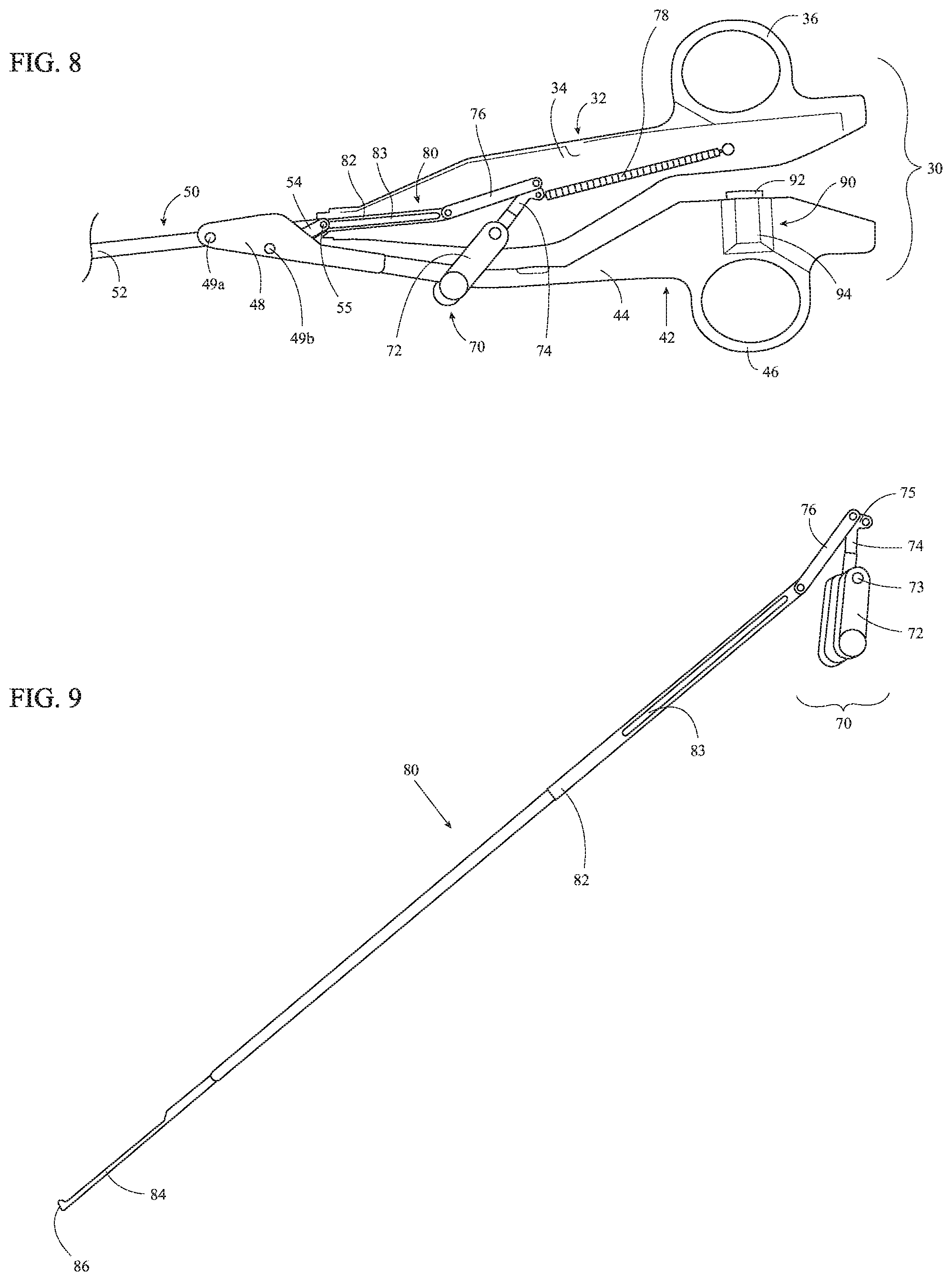
FIG. 8 is a side view of a proximal portion of the forceps of FIG. 1, with the elongated shaft and a portion of a housing of a fixed handle removed;
FIG. 9 is a side view of a trigger assembly and a knife assembly of the forceps of FIG. 1;
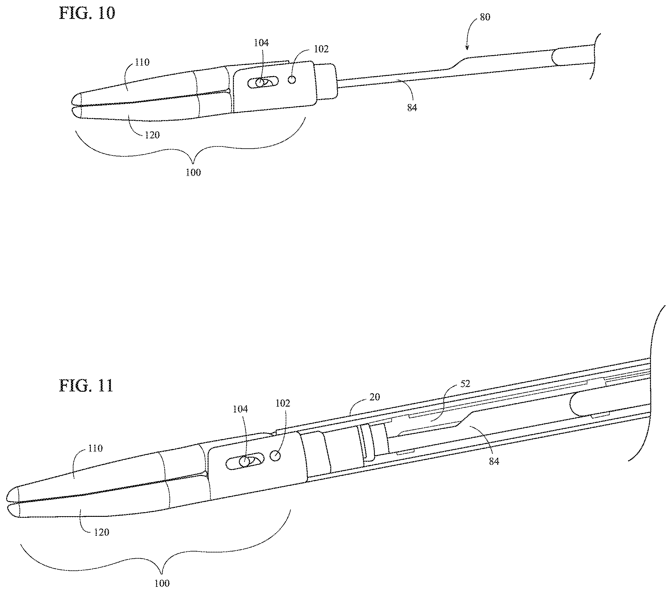
FIG. 10 is a side view of the end effector assembly of the forceps of FIG. 1 including a knife of the knife assembly of FIG. 8 operably positioned relative thereto; and
FIG. 11 is a side view of a distal portion of the forceps of FIG. 1, with a portion of the elongated shaft removed.
DETAILED DESCRIPTION
Turning to FIG. 1, an electrosurgical forceps provided in accordance with the present disclosure is shown generally identified by reference numeral 10. Forceps 10 is configured for use in VATS procedures and other surgical procedures and generally includes an elongated shaft 20, a handle assembly 30, a drive assembly 50 (FIGS. 3A-3C), a trigger assembly 70, a knife assembly 80 (FIGS. 8 and 9), an activation assembly 90, and an end effector assembly 100 which mutually cooperate to grasp, treat, and/or cut tissue. Forceps 10 further includes an electrosurgical cable (not shown) adapted to connect forceps 10 to a source of energy, e.g., a generator (not shown), although forceps 10 may alternatively be configured as a battery-powered instrument.
With additional reference to FIG. 2, handle assembly 30 is operably coupled to a proximal portion of elongated shaft 20 and includes a pair of handle members: a fixed handle 32 and a movable handle 42. Fixed handle 32 is fixedly engaged with elongated shaft 20 and extends proximally therefrom. Fixed handle 32 includes a body 34 formed from first and second housing components that cooperate to house the internal components of trigger assembly 70 (FIG. 8) as well as knife drive bar 82 of knife assembly 80 (FIG. 9). Fixed handle 32 further includes a finger ring 36 disposed on a proximal portion of body 34. Finger ring 36 is configured to receive one or more fingers of a user to facilitate grasping and manipulating forceps 10.
Movable handle 42 of handle assembly 30 includes a body 44 formed from first and second housing components that cooperate to retain activation assembly 90 partially within body 44 and in operable position relative to fixed handle 32, as detailed below. The electrosurgical cable (not shown) of forceps 10 is configured to operably couple to movable handle 42 while the internal wires (not shown) thereof are configured to extend through body 44 of movable handle 42 and elongated shaft 20 to end effector assembly 100 (FIG. 1) to electrically couple end effector assembly 100 (FIG. 1) and activation assembly 90 with the source of energy (not shown). Movable handle 42 further includes a finger ring 46 disposed on a proximal portion of body 44. Finger ring 46 is configured to receive one or more fingers of a user to facilitate grasping and manipulating forceps 10.
Referring to FIGS. 3A-3C, movable handle 42 additionally includes a clevis 48 extending distally from a distal portion of body 44. Clevis 48 defines a bifurcated configuration including first and second spaced-apart clevis members. The first and second spaced-apart clevis member of clevis 48 are configured for positioning on either side of elongated shaft 20 such that elongated shaft 20 is at least partially received within clevis 48. Clevis 48 is configured to operably couple movable handle 42 with elongated shaft 20 and drive assembly 50. Distal and proximal pins 49a, 49b are fixed relative to clevis 48 and extend transversely between the first and second spaced-apart clevis members of clevis 48. Distal pin 49a is configured to pivotably couple clevis 48 to a proximal portion of drive bar 52 of drive assembly 50. Elongated shaft 20 defines a pair of opposed slots 22 (only one is shown) through which distal pin 49a extends to enable coupling of clevis 48 and drive bar 52 with elongated shaft 20 disposed therebetween. Proximal pin 49b is configured to pivotably couple clevis 48 to a distal portion of linkage 54 of drive assembly 50. Elongated shaft 20 defines a cut-out 24 configured to enable pivoting of movable handle 42 relative to fixed handle 32 and elongated shaft 20, as detailed below.
Drive assembly 50 of forceps 10, as noted above, includes drive bar 52 and linkage 54. Drive bar 52 is slidably disposed within elongated shaft 20 and includes a proximal portion that is pivotably coupled to clevis 48 of movable handle 42 via distal pin 49a. A distal portion of linkage 54 extends through cut-out 24 of elongated shaft 20 and is pivotably coupled to clevis 48 via proximal pin 49b. A proximal portion of linkage 54 extends through cut-out 24 into elongated shaft 20 and is pivotably coupled to elongated shaft 20 within elongated shaft 20 via a linkage pin 55. Linkage pin 55 and distal pin 49a are both aligned on a longitudinal axis "X-X" of elongated shaft 20.
As a result of the above-detailed configuration of movable handle 42 and drive assembly 50, pivoting of movable handle 42 relative to fixed handle 32 between an open position and a closed position translates drive bar 52 through elongated shaft 20. More specifically, pivoting of movable handle 42 towards fixed handle 32, e.g., towards the closed position, translates drive bar 52 distally through elongated shaft 20, while pivoting of movable handle 42 away from fixed handle 32, e.g., towards the open position, translates drive bar 52 proximally through elongated shaft 20.
As movable handle 42 is pivoted towards the closed position, the distal portion of linkage 54 is pivoted towards an aligned orientation relative to elongated shaft 20 and, thus, proximal pin 49b is moved towards longitudinal axis "X-X" of elongated shaft 20. The configuration of handle assembly 30, elongated shaft 20, and/or drive assembly 50 inhibits linkage 54 from reaching an aligned position relative to longitudinal axis "X-X" of elongated shaft 20 and, thus, inhibits proximal pin 49b from reaching an over-center position relative to linkage pin 55, distal pin 49a, and longitudinal axis "X-X" of elongated shaft 20. As such, movable handle 42 remains freely movable relative to fixed handle 32 and is not locked in position relative thereto, as is the case when an over-center position is achieved.
Despite being inhibited from reaching an over-center position, proximal pin 49b is configured to move at least partially into cut-out 24 of elongated shaft 20 as movable handle 42 is moved to the closed position to achieve a near-over-center position. This near-over-center position reduces the forces necessary to pivot movable handle 42 towards fixed handle 32 as movable handle 42 approaches the closed position without permitting locking of the movable handle 42. The term near-over-center position, for the purposes herein, corresponds to a position wherein proximal pin 49b is disposed at least partially within cut-out 24 of elongated shaft 20 and, thus, is at least partially inside the outer diameter of elongated shaft 20. As such, the near-over-center position of proximal pin 49b corresponds to a radial distance between longitudinal axis "X-X" of elongated shaft 20 and proximal pin 49b that is equal to or less than the radius of elongated shaft 20 plus the diameter of proximal pin 49b. In embodiments where elongated shaft 20 defines a rectangular or other non-cylindrical configuration, the near-over-center position of proximal pin 49b corresponds to a radial distance between longitudinal axis "X-X" of elongated shaft 20 and proximal pin 49b that is equal to or less than half of the corresponding transverse dimension of elongated shaft 20 (taken along a line perpendicular to longitudinal axis "X-X" and intersecting proximal pin 49b) plus the diameter of proximal pin 49b.
Referring to FIGS. 1 and 4-5B, end effector assembly 100 is coupled to a distal portion of elongated shaft 20 and includes first and second jaw members 110, 120. One or both of jaw members 110, 120 is pivotable relative to the other and the elongated shaft 20 about a pivot pin 102. Each jaw member 110, 120 includes a proximal flange 111, 121 and a distal jaw body 112, 122 supporting an electrically-conductive tissue-contacting surface 114, 124. Tissue-contacting surfaces 114, 124 are electrically coupled to activation assembly 90 (FIG. 1) and the source of energy (not shown), e.g., via the wires (not shown) extending through the electrosurgical cable (not shown), movable handle 42, and elongated shaft 20, such that energy may be selectively supplied to tissue-contacting surface 114 and/or tissue-contacting surface 124 and conducted through tissue grasped between jaw members 110, 120 to treat, e.g., seal, tissue.
Proximal flanges 111, 121 of jaw members 110, 120 are pivotably coupled to one another via pivot pin 102. End effector assembly 100 is configured as a unilateral assembly, wherein jaw member 120 is fixed relative to elongated shaft 20 and jaw member 110 is pivotable about pivot pin 102 relative to elongated shaft 20 and fixed jaw member 120. However, end effector assembly 100 may alternatively be configured as a bilateral assembly, where both jaw member 110 and jaw member 120 are movable about pivot pin 102 relative to one another and elongated shaft 20. For the purposes herein, the terms "movement of the jaw members," "pivoting of the jaw members," and like terms are understood to encompass both unilateral and bilateral configurations. In the illustrated unilateral configuration, proximal flange 121 of jaw member 120 may be fixedly engaged to elongated shaft 20 via welding or other suitable engagement. Pivot pin 102 may be welded, on either side thereof, to proximal flange 121 of jaw member 120 and pivotably disposed within an aperture defined through proximal flange 111 of jaw member 110. Other configurations are also contemplated, for example, using a clip similar to that detailed below with respect to cam pin 104 and clip 106 (FIGS. 6A-6B).
Proximal flanges 111, 121 of jaw members 110, 120 define oppositely-oriented U-shaped configurations. One of the proximal flanges, e.g., proximal flange 121 of jaw member 120, may surround the proximal flange, e.g., proximal flange 111 of jaw member 110, of the other jaw member, as illustrated (see FIG. 6A). Alternatively, proximal flanges 111, 121 may be disposed in an overlapping, offset configuration. Each proximal flange 111, 121 defines a pair of cam slots 116, 126 therethrough. Cam slots 116 of proximal flange 111 of jaw member 110 are angled relative to cam slots 126 of proximal flange 121 of jaw member 120. Cam slots 116, 126 are configured to receive a cam pin 104 that extends through an aperture defined through a distal portion of drive bar 52. As a result of this configuration, translation of drive bar 52 through elongated shaft 20, e.g., in response to pivoting of movable handle 42 (FIG. 1) between the open an closed positions, pivots jaw members 110, 120 between spaced-apart and approximated positions for grasping tissue therebetween. More specifically, cam slots 116, 126 are oriented such that distal translation of drive bar 52 and, thus, cam pin 104, effects pivoting of jaw members 110, 120 from the spaced-apart position towards the approximated position, and such that proximal translation of drive bar 52 and, thus, cam pin 104 pivots jaw members 110, 120 towards the spaced-apart position.
Referring to FIGS. 6A and 6B, a clip 106 is provided to operably couple cam pin 104 with jaw members 110, 120 and drive bar 52, and to retain cam pin 104 in position without the need for welding (or otherwise affixing) cam pin 104 to drive bar 52. Such a configuration is advantageous in that welding (or otherwise affixing) cam pin 104 to drive bar 52 is difficult due to the necessity for drive bar 52 to be operably positioned between jaw members 110, 120 and cam pin 104 inserted therebetween prior to welding cam pin 104 thereto.
Clip 106 includes a body 107a having a pair of resilient, semi-annular side fingers 107b (only one is shown) extending from either side thereof and a central finger 107c extending between side fingers 107b. Cam pin 104 defines an annular groove 105 to facilitate engagement of clip 106 thereabout. Side fingers 107b, at the free ends thereof and in their at-rest position, are spaced-apart a distance smaller than the diameter of the portion of clip 106 that defines groove 105.
In order to operably couple jaw members 110, 120 and drive bar 52 with one another via cam pin 104, jaw members 110, 120 are first aligned such that cam slots 116, 126 of proximal flanges 111, 121 of jaw members 110, 120, respectively, are aligned with one another. Drive bar 52 is inserted between proximal flanges 111, 121 such that the aperture defined within drive bar 52 is aligned with cam slots 116, 126. Once cam slots 116, 126 are aligned with one another and the aperture of drive bar 52, cam pin 104 may be inserted, from either side of end effector assembly 100, through cam slots 116, 126 and the aperture of drive bar 52. In the inserted position of cam pin 104, groove 105 is exposed between drive bar 52 and flanges 111, 121 to enable distal insertion of clip 106 between drive bar 52 and flanges 111, 121 and into engagement with cam pin 104.
In order to engage clip 106 about cam pin 104, clip 106 is aligned with groove 105 of cam pin 104 and moved transversely towards clip 106. As clip 106 is moved into contact with cam pin 104, side fingers 107b contact the inner surface of can pin defining groove 105 and are flexed outwardly relative to one another to widen the gap therebetween and permit cam pin 104 to pass therebetween. Once cam pin 104 is positioned more than halfway within clip 106, e.g., once side fingers 107b clear the diameter of cam pin 104, side fingers 107b are returned under bias inwardly into engagement within groove 105, thereby retaining clip 106 about cam pin 104. Upon engagement of clip 106 about cam pin 104, central finger 107c is also disposed within groove 105.
With clip 106 engaged about cam pin 104, cam pin 104 is inhibited from sliding laterally out of engagement with cam slots 116, 126 and/or the aperture of drive bar 52. Thus, cam pin 104 is retained in operable engagement within cam slots 116, 126 and the aperture of drive bar 52 such that translation of drive bar 52 relative to end effector assembly 100 translates cam pin 104 through cam slots 116, 126 to pivot jaw members 110, 120 between the spaced-apart and approximated positions.
With reference to FIGS. 4-5B, distal jaw bodies 112, 122 of jaw members 110, 120 extend distally from proximal flanges 111, 121, respectively, and, as noted above, support respective electrically-conductive tissue-contacting surfaces 114, 124 thereon. Distal jaw bodies 112, 122 and, thus, tissue-contacting surfaces 114, 124, define curved configurations, although other configurations may also be provided. In the approximated position of jaw members 110, 120, tissue-contacting surfaces 114, 124 are configured to grasp tissue therebetween and, upon activation of activation assembly 90 (FIG. 1), conduct energy therebetween and through grasped tissue to treat, e.g., seal, tissue. Either or both tissue-contacting plates 114, 124 may further define a longitudinally-extending knife channel 117, 127 extending therethrough. Knife channel(s) 117, 127 are configured to receive a knife 84 of knife assembly 80 (FIG. 9) to facilitate reciprocation of knife 84 (FIG. 9) between jaw members 110, 120 to cut tissue disposed therebetween, e.g., upon actuation of rotatable trigger 72 of trigger assembly 70 (see FIG. 9).
Referring additionally to FIG. 7, the distal jaw body 112, 122 of one or both of jaw members 110, 120 further includes a plurality of vent holes 118, 128 defined therethrough (only vent holes 118 of jaw member 110 are shown in FIG. 7; the vent holes of jaw member 120 may be similar in embodiments where so provided). Vent holes 118, 128 are arranged longitudinally along jaw member 110 and extend completely through distal jaw bodies 112, 122. More specifically, vent holes 118, 128 are aligned with and disposed in communication with knife channels 117, 127 of jaw members 110, 120. As such, steam generated during tissue treatment may escape the area between jaw members 110, 120 via knife channels 117, 127 and vent holes 118, 128.
Turning to FIGS. 8-11, trigger assembly 70 and knife assembly 80 cooperate to enable selective deployment of knife 84 between a retracted position, wherein knife 84 is disposed proximally of jaw members 110, 120, and an extended position, wherein knife 84 extends at least partially through knife channels 117, 127 (FIGS. 5A-5B) between jaw members 110, 120. Trigger assembly 70 is operably coupled to and partially disposed within body 34 of fixed handle 32. Trigger assembly 70 includes a rotatable trigger 72, a first linkage 74, a second linkage 76, and a spring 78. Rotatable trigger 72 defines a bifurcated configuration and extends from body 34 of fixed handle 32 towards movable handle 42. In the closed position of handle assembly 30, the bifurcated rotatable trigger 72 at least partially surrounds body 44 of movable handle 42, thus enabling actuation of rotatable trigger 72 from either side of forceps 10 (FIG. 1). Rotatable trigger 72 is pivotably coupled to fixed handle 32 about a pivot 73.
First linkage 74 of trigger assembly 70 is disposed within body 34 of fixed handle 32. First linkage 74 is pivotably coupled to fixed handle 32 about pivot 73 towards a first end of first linkage 74 and is engaged with rotatable trigger 72 such that pivoting of rotatable trigger about pivot 73 likewise pivots first linkage 74 about pivot 73. The second end of first linkage 74 defines a Y-connector 75. Spring 78 is disposed within body 34 of fixed handle 32 and includes a first end that is fixed relative to body 34 and a second end that is engaged with one of the prongs of Y-connector 75. Spring 78 is configured to bias first linkage 74 and, thus, rotatable trigger 72, towards an un-actuated position. Spring 78 also biases knife 84 towards the retracted position.
Second linkage 76 operably couples first linkage 74 and, thus rotatable trigger 72, with knife assembly 80. More specifically, second linkage 76 is coupled to the other prong of Y-connector 75 of first linkage 74 towards the proximal end of second linkage 76, and is coupled to a proximal portion of knife drive bar 82 towards the distal end of second linkage 76. As a result, pivoting of rotatable trigger 72 about pivot 73 pivots first linkage 74 about pivot 73 to urge second linkage 76 distally through body 34 of fixed handle 32.
Knife assembly 80 includes knife drive bar 82 and knife 84. A proximal portion of knife drive bar 82 is pivotably coupled to a distal portion of second linkage 76, and a distal portion of knife drive bar 82 is fixedly engaged with a proximal portion of knife 84 with knife 84 extending distally therefrom. Knife drive bar 82 defines a slot 83 configured to receive distal pin 49a and linkage pin 55 (see FIGS. 3A-3C) to enable knife drive bar 82 to slide relative thereto. Knife 84 defines a distal cutting edge 86. In operation, pivoting of rotatable trigger 72 from an un-actuated position to an actuated position pivots first linkage 74 to urge second linkage 76 distally through body 34 of fixed handle 32, thereby urging knife drive bar 82 distally through elongated shaft 20 and translating knife 84 from the retracted position to the extended position. Release of rotatable trigger 72 returns rotatable trigger 72 back towards the un-actuated position under the bias of spring 78, thereby returning first linkage 74, second linkage 76, and knife drive bar 82 such that knife 84 is returned to the retracted position.
Referring again to FIGS. 1 and 2, activation assembly 90, as noted above, is at least partially retained within body 44 of movable handle 42. Activation asse
D00000
D00001
D00002
D00003
D00004
D00005
D00006
XML
uspto.report is an independent third-party trademark research tool that is not affiliated, endorsed, or sponsored by the United States Patent and Trademark Office (USPTO) or any other governmental organization. The information provided by uspto.report is based on publicly available data at the time of writing and is intended for informational purposes only.
While we strive to provide accurate and up-to-date information, we do not guarantee the accuracy, completeness, reliability, or suitability of the information displayed on this site. The use of this site is at your own risk. Any reliance you place on such information is therefore strictly at your own risk.
All official trademark data, including owner information, should be verified by visiting the official USPTO website at www.uspto.gov. This site is not intended to replace professional legal advice and should not be used as a substitute for consulting with a legal professional who is knowledgeable about trademark law.