Robotic devices with on board control and related systems and devices
Farritor , et al.
U.S. patent number 10,624,704 [Application Number 15/661,147] was granted by the patent office on 2020-04-21 for robotic devices with on board control and related systems and devices. This patent grant is currently assigned to Board of Regents of the University of Nebraska. The grantee listed for this patent is Board of Regents of the University of Nebraska. Invention is credited to Philip Chu, Jason Dumpert, Shane Farritor, Nishant Kumar, Erik Mumm, Yutaka Tsutano.


View All Diagrams
| United States Patent | 10,624,704 |
| Farritor , et al. | April 21, 2020 |
Robotic devices with on board control and related systems and devices
Abstract
The embodiments disclosed herein relate to various medical device components, including components that can be incorporated into robotic and/or in vivo medical devices. Certain embodiments include various modular medical devices for in vivo medical procedures.
| Inventors: | Farritor; Shane (Lincoln, NE), Mumm; Erik (Longmont, CO), Chu; Philip (Friendswood, TX), Kumar; Nishant (Bergenfield, NJ), Dumpert; Jason (Omaha, NE), Tsutano; Yutaka (Lincoln, NE) | ||||||||||
|---|---|---|---|---|---|---|---|---|---|---|---|
| Applicant: |
|
||||||||||
| Assignee: | Board of Regents of the University
of Nebraska (Lincoln, NE) |
||||||||||
| Family ID: | 50433284 | ||||||||||
| Appl. No.: | 15/661,147 | ||||||||||
| Filed: | July 27, 2017 |
Prior Publication Data
| Document Identifier | Publication Date | |
|---|---|---|
| US 20180071036 A1 | Mar 15, 2018 | |
Related U.S. Patent Documents
| Application Number | Filing Date | Patent Number | Issue Date | ||
|---|---|---|---|---|---|
| 13573849 | Oct 9, 2012 | 9770305 | |||
| 61680809 | Aug 8, 2012 | ||||
| Current U.S. Class: | 1/1 |
| Current CPC Class: | A61B 34/30 (20160201); A61B 17/29 (20130101); A61B 34/00 (20160201); A61B 17/00234 (20130101); A61B 34/37 (20160201); A61B 2217/007 (20130101); A61B 90/30 (20160201); A61B 2034/302 (20160201); A61B 90/361 (20160201); A61B 2217/005 (20130101); A61B 2017/2906 (20130101) |
| Current International Class: | A61B 34/30 (20160101); A61B 90/30 (20160101); A61B 90/00 (20160101); A61B 34/37 (20160101); A61B 17/29 (20060101); A61B 17/00 (20060101); A61B 34/00 (20160101) |
| Field of Search: | ;318/560,561 |
References Cited [Referenced By]
U.S. Patent Documents
| 3870264 | March 1975 | Robinson |
| 3989952 | November 1976 | Timberlake et al. |
| 4258716 | March 1981 | Sutherland |
| 4278077 | July 1981 | Mizumoto |
| 4538594 | September 1985 | Boebel et al. |
| 4568311 | February 1986 | Miyake |
| 4736645 | April 1988 | Zimmer |
| 4771652 | September 1988 | Zimmer |
| 4852391 | August 1989 | Ruch et al. |
| 4896015 | January 1990 | Taboada et al. |
| 4922755 | May 1990 | Oshiro et al. |
| 4922782 | May 1990 | Kawai |
| 4990050 | February 1991 | Tsuge et al. |
| 5019968 | May 1991 | Wang et al. |
| 5172639 | December 1992 | Wiesman et al. |
| 5195388 | March 1993 | Zona et al. |
| 5201325 | April 1993 | McEwen et al. |
| 5271384 | December 1993 | McEwen et al. |
| 5284096 | February 1994 | Pelrine et al. |
| 5297443 | March 1994 | Wentz |
| 5297536 | March 1994 | Wilk |
| 5304899 | April 1994 | Sasaki et al. |
| 5307447 | April 1994 | Asano et al. |
| 5353807 | October 1994 | DeMarco |
| 5363935 | November 1994 | Schempf et al. |
| 5382885 | January 1995 | Salcudean et al. |
| 5388528 | February 1995 | Pelrine et al. |
| 5436542 | July 1995 | Petelin et al. |
| 5441494 | August 1995 | Ortiz |
| 5458131 | October 1995 | Wilk |
| 5458583 | October 1995 | McNeely et al. |
| 5458598 | October 1995 | Feinberg et al. |
| 5471515 | November 1995 | Fossum et al. |
| 5515478 | May 1996 | Wang |
| 5524180 | June 1996 | Wang et al. |
| 5553198 | September 1996 | Wang et al. |
| 5562448 | October 1996 | Mushabac |
| 5588442 | December 1996 | Scovil et al. |
| 5620417 | April 1997 | Jang et al. |
| 5623582 | April 1997 | Rosenberg |
| 5624380 | April 1997 | Takayama et al. |
| 5624398 | April 1997 | Smith et al. |
| 5632761 | May 1997 | Smith et al. |
| 5645520 | July 1997 | Nakamura et al. |
| 5657429 | August 1997 | Wang et al. |
| 5657584 | August 1997 | Hamlin |
| 5672168 | September 1997 | de la Torre et al. |
| 5674030 | October 1997 | Sigel |
| 5728599 | March 1998 | Rosteker et al. |
| 5736821 | April 1998 | Suyaman et al. |
| 5754741 | May 1998 | Wang et al. |
| 5762458 | June 1998 | Wang et al. |
| 5769640 | June 1998 | Jacobus et al. |
| 5791231 | August 1998 | Cohn et al. |
| 5792135 | August 1998 | Madhani et al. |
| 5797538 | August 1998 | Heaton et al. |
| 5797900 | August 1998 | Madhani et al. |
| 5807377 | September 1998 | Madhani et al. |
| 5808665 | September 1998 | Green |
| 5815640 | September 1998 | Wang et al. |
| 5825982 | October 1998 | Wright et al. |
| 5841950 | November 1998 | Wang et al. |
| 5845646 | December 1998 | Lemelson |
| 5855583 | January 1999 | Wang et al. |
| 5876325 | March 1999 | Mizuno et al. |
| 5878193 | March 1999 | Wang et al. |
| 5878783 | March 1999 | Smart |
| 5895417 | April 1999 | Pomeranz et al. |
| 5906591 | May 1999 | Dario et al. |
| 5907664 | May 1999 | Wang et al. |
| 5910129 | June 1999 | Koblish et al. |
| 5911036 | June 1999 | Wright et al. |
| 5971976 | October 1999 | Wang et al. |
| 5993467 | November 1999 | Yoon |
| 6001108 | December 1999 | Wang et al. |
| 6007550 | December 1999 | Wang et al. |
| 6030365 | February 2000 | Laufer |
| 6031371 | February 2000 | Smart |
| 6058323 | May 2000 | Lemelson |
| 6063095 | May 2000 | Wang et al. |
| 6066090 | May 2000 | Yoon |
| 6102850 | August 2000 | Wang et al. |
| 6107795 | August 2000 | Smart |
| 6132368 | October 2000 | Cooper |
| 6132441 | October 2000 | Grace |
| 6139563 | October 2000 | Cosgrove, III et al. |
| 6156006 | December 2000 | Brosens et al. |
| 6159146 | December 2000 | El Gazayerli |
| 6162171 | December 2000 | Ng et al. |
| D438617 | March 2001 | Cooper et al. |
| 6206903 | March 2001 | Ramans |
| D441076 | April 2001 | Cooper et al. |
| 6223100 | April 2001 | Green |
| D441862 | May 2001 | Cooper et al. |
| 6238415 | May 2001 | Sepetka et al. |
| 6240312 | May 2001 | Alfano et al. |
| 6241730 | June 2001 | Alby |
| 6244809 | June 2001 | Wang et al. |
| 6246200 | June 2001 | Blumenkranz et al. |
| D444555 | July 2001 | Cooper et al. |
| 6286514 | September 2001 | Lemelson |
| 6296635 | October 2001 | Smith et al. |
| 6309397 | October 2001 | Julian et al. |
| 6309403 | October 2001 | Minoret et al. |
| 6312435 | November 2001 | Wallace et al. |
| 6321106 | November 2001 | Lemelson |
| 6327492 | December 2001 | Lemelson |
| 6331181 | December 2001 | Tiemey et al. |
| 6346072 | February 2002 | Cooper |
| 6352503 | March 2002 | Matsui et al. |
| 6364888 | April 2002 | Niemeyer et al. |
| 6371952 | April 2002 | Madhani et al. |
| 6394998 | May 2002 | Wallace et al. |
| 6398726 | June 2002 | Ramans et al. |
| 6400980 | June 2002 | Lemelson |
| 6408224 | June 2002 | Lemelson |
| 6424885 | July 2002 | Niemeyer et al. |
| 6432112 | August 2002 | Brock et al. |
| 6436107 | August 2002 | Wang et al. |
| 6441577 | August 2002 | Blumenkranz et al. |
| 6450104 | September 2002 | Grant et al. |
| 6451027 | September 2002 | Cooper et al. |
| 6454758 | September 2002 | Thompson et al. |
| 6459926 | October 2002 | Nowlin et al. |
| 6463361 | October 2002 | Wang et al. |
| 6468203 | October 2002 | Belson |
| 6468265 | October 2002 | Evans et al. |
| 6470236 | October 2002 | Ohtsuki |
| 6491691 | December 2002 | Morley et al. |
| 6491701 | December 2002 | Nemeyer et al. |
| 6493608 | December 2002 | Niemeyer et al. |
| 6496099 | December 2002 | Wang et al. |
| 6508413 | January 2003 | Bauer et al. |
| 6512345 | January 2003 | Borenstein |
| 6522906 | February 2003 | Salisbury, Jr. et al. |
| 6544276 | April 2003 | Azizi |
| 6548982 | April 2003 | Papanikolopoulos et al. |
| 6554790 | April 2003 | Moll |
| 6565554 | May 2003 | Niemeyer |
| 6574355 | June 2003 | Green |
| 6587750 | July 2003 | Gerbi et al. |
| 6591239 | July 2003 | McCall et al. |
| 6594552 | July 2003 | Nowlin et al. |
| 6610007 | August 2003 | Belson et al. |
| 6620173 | September 2003 | Gerbi et al. |
| 6642836 | November 2003 | Wang et al. |
| 6645196 | November 2003 | Nixon et al. |
| 6646541 | November 2003 | Wang et al. |
| 6648814 | November 2003 | Kim et al. |
| 6659939 | December 2003 | Moll et al. |
| 6661571 | December 2003 | Shioda et al. |
| 6671581 | December 2003 | Niemeyer et al. |
| 6676684 | January 2004 | Morley et al. |
| 6684129 | January 2004 | Salisbury, Jr. et al. |
| 6685648 | February 2004 | Flaherty et al. |
| 6685698 | February 2004 | Morley et al. |
| 6687571 | February 2004 | Byme et al. |
| 6692485 | February 2004 | Brock et al. |
| 6699177 | March 2004 | Wang et al. |
| 6699235 | March 2004 | Wallace et al. |
| 6702734 | March 2004 | Kim et al. |
| 6702805 | March 2004 | Stuart |
| 6714839 | March 2004 | Salisbury, Jr. et al. |
| 6714841 | March 2004 | Wright et al. |
| 6719684 | April 2004 | Kim et al. |
| 6720988 | April 2004 | Gere et al. |
| 6726699 | April 2004 | Wright et al. |
| 6728599 | April 2004 | Wright et al. |
| 6730021 | May 2004 | Vassiliades, Jr. et al. |
| 6731988 | May 2004 | Green |
| 6746443 | June 2004 | Morley et al. |
| 6764441 | July 2004 | Chiel et al. |
| 6764445 | July 2004 | Ramans et al. |
| 6766204 | July 2004 | Niemeyer et al. |
| 6770081 | August 2004 | Cooper et al. |
| 6774597 | August 2004 | Borenstein |
| 6776165 | August 2004 | Jin |
| 6780184 | August 2004 | Tanrisever |
| 6783524 | August 2004 | Anderson et al. |
| 6785593 | August 2004 | Wang et al. |
| 6788018 | September 2004 | Blumenkranz |
| 6792663 | September 2004 | Krzyzanowski |
| 6793653 | September 2004 | Sanchez et al. |
| 6799065 | September 2004 | Niemeyer |
| 6799088 | September 2004 | Wang et al. |
| 6801325 | October 2004 | Farr et al. |
| 6804581 | October 2004 | Wang et al. |
| 6810281 | October 2004 | Brock et al. |
| 6817972 | November 2004 | Snow |
| 6817974 | November 2004 | Cooper et al. |
| 6817975 | November 2004 | Farr et al. |
| 6820653 | November 2004 | Schempf et al. |
| 6824508 | November 2004 | Kim et al. |
| 6824510 | November 2004 | Kim et al. |
| 6832988 | December 2004 | Sprout |
| 6832996 | December 2004 | Woloszko et al. |
| 6836703 | December 2004 | Wang et al. |
| 6837846 | January 2005 | Jaffe et al. |
| 6837883 | January 2005 | Moll et al. |
| 6839612 | January 2005 | Sanchez et al. |
| 6840938 | January 2005 | Morley et al. |
| 6852107 | February 2005 | Wang et al. |
| 6858003 | February 2005 | Evans et al. |
| 6860346 | March 2005 | Burt et al. |
| 6860877 | March 2005 | Sanchez et al. |
| 6866671 | March 2005 | Tiemey et al. |
| 6870343 | March 2005 | Borenstein et al. |
| 6871117 | March 2005 | Wang et al. |
| 6871563 | March 2005 | Choset et al. |
| 6879880 | April 2005 | Nowlin et al. |
| 6892112 | May 2005 | Wang et al. |
| 6899705 | May 2005 | Niemeyer |
| 6902560 | June 2005 | Morley et al. |
| 6905460 | June 2005 | Wang et al. |
| 6905491 | June 2005 | Wang et al. |
| 6911916 | June 2005 | Wang et al. |
| 6917176 | July 2005 | Schempf et al. |
| 6933695 | August 2005 | Blumenkranz |
| 6936001 | August 2005 | Snow |
| 6936003 | August 2005 | Iddan |
| 6936042 | August 2005 | Wallace et al. |
| 6943663 | September 2005 | Wang et al. |
| 6949096 | September 2005 | Davison et al. |
| 6951535 | October 2005 | Ghodoussi et al. |
| 6965812 | November 2005 | Wang et al. |
| 6974411 | December 2005 | Belson |
| 6974449 | December 2005 | Niemeyer |
| 6979423 | December 2005 | Moll |
| 6984203 | January 2006 | Tartaglia et al. |
| 6984205 | January 2006 | Gazdzinski |
| 6991627 | January 2006 | Madhani et al. |
| 6993413 | January 2006 | Sunaoshi |
| 6994703 | February 2006 | Wang et al. |
| 6994708 | February 2006 | Manzo |
| 6997908 | February 2006 | Carrillo, Jr. et al. |
| 7025064 | April 2006 | Wang et al. |
| 7027892 | April 2006 | Wang et al. |
| 7033344 | April 2006 | Imran |
| 7039453 | May 2006 | Mullick |
| 7042184 | May 2006 | Oleynikov et al. |
| 7048745 | May 2006 | Tierney et al. |
| 7053752 | May 2006 | Wang et al. |
| 7063682 | June 2006 | Whayne et al. |
| 7066879 | June 2006 | Fowler et al. |
| 7066926 | June 2006 | Wallace et al. |
| 7074179 | July 2006 | Wang et al. |
| 7077446 | July 2006 | Kameda et al. |
| 7083571 | August 2006 | Wang et al. |
| 7083615 | August 2006 | Peterson et al. |
| 7087049 | August 2006 | Nowlin et al. |
| 7090683 | August 2006 | Brock et al. |
| 7097640 | August 2006 | Wang et al. |
| 7105000 | September 2006 | McBrayer |
| 7107090 | September 2006 | Salisbury, Jr. et al. |
| 7109678 | September 2006 | Kraus et al. |
| 7118582 | October 2006 | Wang et al. |
| 7121781 | October 2006 | Sanchez et al. |
| 7125403 | October 2006 | Julian et al. |
| 7126303 | October 2006 | Farritor et al. |
| 7147650 | December 2006 | Lee |
| 7155315 | December 2006 | Niemeyer et al. |
| 7155316 | December 2006 | Sutherland |
| 7169141 | January 2007 | Brock et al. |
| 7182025 | February 2007 | Ghorbel et al. |
| 7182089 | February 2007 | Ries |
| 7199545 | April 2007 | Oleynikov et al. |
| 7206626 | April 2007 | Quaid, III |
| 7206627 | April 2007 | Abovitz et al. |
| 7210364 | May 2007 | Ghorbel et al. |
| 7214230 | May 2007 | Brock et al. |
| 7217240 | May 2007 | Snow |
| 7239940 | July 2007 | Wang et al. |
| 7250028 | July 2007 | Julian et al. |
| 7259652 | August 2007 | Wang et al. |
| 7273488 | September 2007 | Nakamura et al. |
| 7311107 | December 2007 | Harel et al. |
| 7339341 | March 2008 | Oleynikov et al. |
| 7372229 | May 2008 | Farritor et al. |
| 7447537 | November 2008 | Funda et al. |
| 7492116 | February 2009 | Oleynikov et al. |
| 7566300 | July 2009 | Devierre et al. |
| 7574250 | August 2009 | Niemeyer |
| 7637905 | December 2009 | Saadat et al. |
| 7645230 | January 2010 | Mikkaichi et al. |
| 7655004 | February 2010 | Long |
| 7670329 | March 2010 | Flaherty et al. |
| 7731727 | June 2010 | Sauer |
| 7762825 | July 2010 | Burbank et al. |
| 7772796 | August 2010 | Farritor et al. |
| 7785251 | August 2010 | Wilk |
| 7785333 | August 2010 | Miyamoto et al. |
| 7789825 | September 2010 | Nobis et al. |
| 7794494 | September 2010 | Sahatjian et al. |
| 7865266 | January 2011 | Moll et al. |
| 7960935 | June 2011 | Farritor et al. |
| 8021358 | September 2011 | Doyle et al. |
| 8353897 | January 2013 | Doyle et al. |
| 9089353 | July 2015 | Farritor et al. |
| 2001/0018591 | August 2001 | Brook et al. |
| 2001/0049497 | December 2001 | Kalloo et al. |
| 2002/0003173 | January 2002 | Bauer et al. |
| 2002/0013601 | January 2002 | Nobles et al. |
| 2002/0026186 | February 2002 | Woloszko et al. |
| 2002/0038077 | March 2002 | de la Torre et al. |
| 2002/0065507 | May 2002 | Zadno-Azizi |
| 2002/0091374 | June 2002 | Cooper |
| 2002/0103417 | August 2002 | Gazdzinski |
| 2002/0111535 | August 2002 | Kim et al. |
| 2002/0120254 | August 2002 | Julian et al. |
| 2002/0128552 | September 2002 | Nowlin et al. |
| 2002/0140392 | October 2002 | Borenstein et al. |
| 2002/0147487 | October 2002 | Sundquist et al. |
| 2002/0151906 | October 2002 | Demarais et al. |
| 2002/0156347 | October 2002 | Kim et al. |
| 2002/0171385 | November 2002 | Kim et al. |
| 2002/0173700 | November 2002 | Kim et al. |
| 2002/0190682 | December 2002 | Schempf et al. |
| 2003/0020810 | January 2003 | Takizawa et al. |
| 2003/0045888 | March 2003 | Brock et al. |
| 2003/0065250 | April 2003 | Chiel et al. |
| 2003/0089267 | May 2003 | Ghorbel et al. |
| 2003/0092964 | May 2003 | Kim et al. |
| 2003/0097129 | May 2003 | Davison et al. |
| 2003/0100817 | May 2003 | Wang et al. |
| 2003/0114731 | June 2003 | Cadeddu et al. |
| 2003/0135203 | June 2003 | Wang et al. |
| 2003/0139742 | July 2003 | Wampler et al. |
| 2003/0144656 | July 2003 | Ocel et al. |
| 2003/0167000 | September 2003 | Mullick |
| 2003/0172871 | September 2003 | Scherer |
| 2003/0179308 | September 2003 | Zamorano et al. |
| 2003/0181788 | September 2003 | Yokoi et al. |
| 2003/0229268 | December 2003 | Uchiyama et al. |
| 2003/0230372 | December 2003 | Schmidt |
| 2004/0024311 | February 2004 | Quaid |
| 2004/0034282 | February 2004 | Quaid |
| 2004/0034283 | February 2004 | Quaid |
| 2004/0034302 | February 2004 | Abovitz et al. |
| 2004/0050394 | March 2004 | Jin |
| 2004/0070822 | April 2004 | Shioda et al. |
| 2004/0099175 | May 2004 | Perrot et al. |
| 2004/0102772 | May 2004 | Baxter et al. |
| 2004/0106916 | June 2004 | Quaid et al. |
| 2004/0111113 | June 2004 | Nakamura et al. |
| 2004/0117032 | June 2004 | Roth |
| 2004/0138525 | July 2004 | Saadat et al. |
| 2004/0138552 | July 2004 | Harel et al. |
| 2004/0140786 | July 2004 | Borenstein |
| 2004/0153057 | August 2004 | Davison |
| 2004/0173116 | September 2004 | Ghorbel et al. |
| 2004/0176664 | September 2004 | Iddan |
| 2004/0215331 | October 2004 | Chew et al. |
| 2004/0225229 | November 2004 | Viola |
| 2004/0254680 | December 2004 | Sunaoshi |
| 2004/0267326 | December 2004 | Ocel et al. |
| 2005/0014994 | January 2005 | Fowler et al. |
| 2005/0021069 | January 2005 | Feuer et al. |
| 2005/0029978 | February 2005 | Oleynikov et al. |
| 2005/0043583 | February 2005 | Killmann et al. |
| 2005/0049462 | March 2005 | Kanazawa |
| 2005/0054901 | March 2005 | Yoshino |
| 2005/0054902 | March 2005 | Konno |
| 2005/0064378 | March 2005 | Toly |
| 2005/0065400 | March 2005 | Banik et al. |
| 2005/0083460 | April 2005 | Hattori et al. |
| 2005/0095650 | May 2005 | Julius et al. |
| 2005/0096502 | May 2005 | Khalili |
| 2005/0143644 | June 2005 | Gilad et al. |
| 2005/0154376 | July 2005 | Riviere et al. |
| 2005/0165449 | July 2005 | Cadeddu et al. |
| 2005/0283137 | December 2005 | Doyle et al. |
| 2005/0288555 | December 2005 | Binmoeller |
| 2005/0288665 | December 2005 | Woloszko |
| 2006/0020272 | January 2006 | Gildenberg |
| 2006/0046226 | March 2006 | Bergler et al. |
| 2006/0119304 | June 2006 | Farritor et al. |
| 2006/0149135 | July 2006 | Paz |
| 2006/0152591 | July 2006 | Lin |
| 2006/0155263 | July 2006 | Lipow |
| 2006/0195015 | August 2006 | Mullick et al. |
| 2006/0196301 | September 2006 | Oleynikov et al. |
| 2006/0198619 | September 2006 | Oleynikov et al. |
| 2006/0241570 | October 2006 | Wilk |
| 2006/0241732 | October 2006 | Denker |
| 2006/0253109 | November 2006 | Chu |
| 2006/0258954 | November 2006 | Timberlake et al. |
| 2007/0032701 | February 2007 | Fowler et al. |
| 2007/0043397 | February 2007 | Ocel et al. |
| 2007/0055342 | March 2007 | Wu et al. |
| 2007/0080658 | April 2007 | Farritor et al. |
| 2007/0106113 | May 2007 | Ravo |
| 2007/0123748 | May 2007 | Meglan |
| 2007/0142725 | June 2007 | Hardin et al. |
| 2007/0156019 | July 2007 | Larkin et al. |
| 2007/0156211 | July 2007 | Ferren et al. |
| 2007/0167955 | July 2007 | De La Menardiere et al. |
| 2007/0225633 | September 2007 | Ferren et al. |
| 2007/0225634 | September 2007 | Ferren et al. |
| 2007/0241714 | October 2007 | Okeynikov et al. |
| 2007/0244520 | October 2007 | Ferren et al. |
| 2007/0250064 | October 2007 | Darois et al. |
| 2007/0255273 | November 2007 | Fernandez et al. |
| 2008/0004634 | January 2008 | Farritor et al. |
| 2008/0015565 | January 2008 | Davison |
| 2008/0015566 | January 2008 | Livneh |
| 2008/0033569 | February 2008 | Ferren |
| 2008/0045803 | February 2008 | Williams et al. |
| 2008/0058835 | March 2008 | Farritor et al. |
| 2008/0058989 | March 2008 | Oleynikov et al. |
| 2008/0103440 | May 2008 | Ferren et al. |
| 2008/0109014 | May 2008 | de la Pena |
| 2008/0111513 | May 2008 | Farritor et al. |
| 2008/0119870 | May 2008 | Williams et al. |
| 2008/0132890 | June 2008 | Woloszko et al. |
| 2008/0161804 | June 2008 | Rioux et al. |
| 2008/0164079 | July 2008 | Ferren et al. |
| 2008/0183033 | July 2008 | Bern et al. |
| 2008/0221591 | September 2008 | Farritor et al. |
| 2008/0269557 | October 2008 | Marescaux et al. |
| 2008/0269562 | October 2008 | Marescaux et al. |
| 2009/0020724 | January 2009 | Paffrath |
| 2009/0024142 | January 2009 | Ruiz Morales |
| 2009/0048612 | February 2009 | Farritor et al. |
| 2009/0054909 | February 2009 | Farritor et al. |
| 2009/0069821 | March 2009 | Farritor et al. |
| 2009/0076536 | March 2009 | Rentschler et al. |
| 2009/0137952 | May 2009 | Ramamurthy et al. |
| 2009/0143787 | June 2009 | De La Pena |
| 2009/0163929 | June 2009 | Yeung et al. |
| 2009/0171373 | July 2009 | Farritor et al. |
| 2009/0234369 | September 2009 | Bax et al. |
| 2009/0236400 | September 2009 | Cole et al. |
| 2009/0240246 | September 2009 | Devill et al. |
| 2009/0247821 | October 2009 | Rogers |
| 2009/0248038 | October 2009 | Blumenkranz et al. |
| 2009/0281377 | November 2009 | Newell et al. |
| 2009/0305210 | December 2009 | Guru et al. |
| 2010/0010294 | January 2010 | Conlon et al. |
| 2010/0016659 | January 2010 | Weitzner et al. |
| 2010/0016853 | January 2010 | Burbank |
| 2010/0042097 | February 2010 | Newton et al. |
| 2010/0056863 | March 2010 | Dejima et al. |
| 2010/0069710 | March 2010 | Yamatani et al. |
| 2010/0069940 | March 2010 | Miller et al. |
| 2010/0081875 | April 2010 | Fowler et al. |
| 2010/0139436 | June 2010 | Kawashima et al. |
| 2010/0198231 | August 2010 | Manzo et al. |
| 2010/0245549 | September 2010 | Allen et al. |
| 2010/0262162 | October 2010 | Omori |
| 2010/0292691 | November 2010 | Brogna |
| 2010/0318059 | December 2010 | Farritor et al. |
| 2011/0020779 | January 2011 | Hannaford et al. |
| 2011/0071347 | March 2011 | Rogers et al. |
| 2011/0071544 | March 2011 | Steger et al. |
| 2011/0098529 | April 2011 | Ostrovsky et al. |
| 2011/0152615 | June 2011 | Schostek et al. |
| 2011/0224605 | September 2011 | Farritor et al. |
| 2011/0230894 | September 2011 | Simaan et al. |
| 2011/0237890 | September 2011 | Farritor et al. |
| 2011/0238080 | September 2011 | Ranjit et al. |
| 2011/0264078 | October 2011 | Lipow et al. |
| 2011/0270443 | November 2011 | Kamiya et al. |
| 2012/0035582 | February 2012 | Nelson et al. |
| 2012/0109150 | May 2012 | Quaid et al. |
| 2012/0116362 | May 2012 | Kieturakis |
| 2012/0179168 | July 2012 | Farritor et al. |
| 2012/0253515 | October 2012 | Coste-Maniere et al. |
| 2013/0131695 | May 2013 | Scarfogliero et al. |
| 2013/0345717 | December 2013 | Markvicka et al. |
| 2014/0039515 | February 2014 | Mondry et al. |
| 2014/0046340 | February 2014 | Wilson et al. |
| 2014/0058205 | February 2014 | Frederick et al. |
| 2014/0303434 | October 2014 | Farritor et al. |
| 2015/0051446 | February 2015 | Farritor et al. |
| 102821918 | Dec 2012 | CN | |||
| 102010040405 | Mar 2012 | DE | |||
| 1354670 | Oct 2003 | EP | |||
| 2286756 | Feb 2011 | EP | |||
| 2286756 | Feb 2011 | EP | |||
| 2329787 | Jun 2011 | EP | |||
| 2563261 | Mar 2013 | EP | |||
| 05-115425 | May 1993 | JP | |||
| 2006508049 | Sep 1994 | JP | |||
| 07-016235 | Jan 1995 | JP | |||
| 07-136173 | May 1995 | JP | |||
| 7306155 | Nov 1995 | JP | |||
| 08-224248 | Sep 1996 | JP | |||
| 2001500510 | Jan 2001 | JP | |||
| 2001505810 | May 2001 | JP | |||
| 2003220065 | Aug 2003 | JP | |||
| 2004144533 | May 2004 | JP | |||
| 2004-180781 | Jul 2004 | JP | |||
| 2004322310 | Nov 2004 | JP | |||
| 2004329292 | Nov 2004 | JP | |||
| 2006507809 | Mar 2006 | JP | |||
| 2010536436 | Aug 2007 | JP | |||
| 2009106606 | May 2009 | JP | |||
| 2010533045 | Oct 2010 | JP | |||
| 2010536436 | Dec 2010 | JP | |||
| 2011504794 | Feb 2011 | JP | |||
| 2011045500 | Mar 2011 | JP | |||
| 2011115591 | Jun 2011 | JP | |||
| 199221291 | May 1991 | WO | |||
| 2001089405 | Nov 2001 | WO | |||
| 2002082979 | Oct 2002 | WO | |||
| 2002100256 | Dec 2002 | WO | |||
| 2005009211 | Jul 2004 | WO | |||
| 2005044095 | May 2005 | WO | |||
| 2006052927 | Aug 2005 | WO | |||
| 2006005075 | Jan 2006 | WO | |||
| 2006079108 | Jan 2006 | WO | |||
| 2006079108 | Jul 2006 | WO | |||
| 2007011654 | Jan 2007 | WO | |||
| 2007111571 | Oct 2007 | WO | |||
| 2007149559 | Dec 2007 | WO | |||
| 2009023851 | Feb 2009 | WO | |||
| 2009144729 | Dec 2009 | WO | |||
| 2010050771 | May 2010 | WO | |||
| 2011075693 | Jun 2011 | WO | |||
| 2011118646 | Sep 2011 | WO | |||
| 2011135503 | Nov 2011 | WO | |||
| 2013009887 | Jan 2013 | WO | |||
| 2014011238 | Jan 2014 | WO | |||
Other References
|
Franzino, "The Laprotek Surgical System and the Next Generation of Robotics," Surg Clin North Am, 2003 83(6): 1317-1320. cited by applicant . Franklin et al., "Prospective Comparison of Open vs. Laparoscopic Colon Surgery for Carcinoma: Five-Year Results," Dis Colon Rectum, 1996; 39: S35-S46. cited by applicant . Flynn et al., "Tomorrow's surgery: micromotors and microrobots for minimally invasive procedures," Minimally Invasive Surgery & Allied Technologies, 1998; 7(4): 343-352. cited by applicant . Fireman et al., "Diagnosing small bowel Crohn's desease with wireless capsule endoscopy," Gut 2003; 52: 390-392. cited by applicant . Fearing et al., "Wing Transmission for a Micromechanical Flying Insect," Proceedings of the 2000 IEEE International Conference to Robotics & Automation, Apr. 2000; 1509-1516. cited by applicant . Faraz et al., "Engineering Approaches to Mechanical and Robotic Design for Minimaly Invasive Surgery (MIS)," Kluwer Academic Publishers (Boston), 2000, 13pp. cited by applicant . Falcone et al., "Robotic Surgery," Clin. Obstet. Gynecol. 2003, 46(1): 37-43. cited by applicant . Fraulob et al., "Miniature assistance module for robot-assisted heart surgery," Biomed. Tech. 2002, 47 Suppl. 1, Pt. 1: 12-15. cited by applicant . Fukuda et al., "Mechanism and Swimming Experiment of Micro Mobile Robot in Water," Proceedings of the 1994 IEEE International Conference on Robotics and Automation, 1994: 814-819. cited by applicant . Fukuda et al., "Micro Active Catheter System with Multi Degrees of Freedom," Proceedings of the IEEE International Conference on Robotics and Automation, May 1994, pp. 2290-2295. cited by applicant . Fuller et al., "Laparoscopic Trocar Injuries: A Report from a U.S. Food and Drug Administration (FDA) Center for Devices and Radiological Health (CDRH) Systematic Technology Assessment of Medical Products (STAMP) Committe," U.S. Food and Drug Adminstration, available at http://www.fdaJ:?;ov, Finalized: Nov. 7, 2003; Updated: Jun. 24, 2005, 11 pp. cited by applicant . Dumpert et al., "Improving in Vivo Robot Visioin Quality," from the Proceedings of Medicine Meets Virtual Realtiy, Long Beach, CA, Jan. 26-29, 2005. 1 pg. cited by applicant . Dakin et al., "Comparison of laparoscopic skills performance between standard instruments and two surgical robotic systems," Surg Endosc., 2003; 17: 574-579. cited by applicant . Cuschieri, "Technology for Minimal Access Surgery," BMJ, 1999, 319: 1-6. cited by applicant . Grady, "Doctors Try New Surgery for Gallbladder Removal," The New York Times, Apr. 20, 2007, 3 pp. cited by applicant . Choi et al., "Flexure-based Manipulator for Active Handheld Microsurgical Instrument," Proceedings of the 27th Annual International Conference of the IEEE Engineering in Medicine and Biology Society (EMBS), Sep. 2005, 4pp. cited by applicant . Canthasopeephan et al., (2003), "Measuring Forces in Liver Cutting: New Equipment and Experimenal Results," Annals of Biomedical Engineering 31: 1372-1382. cited by applicant . Cavusoglu et al., "Robotics for Telesurgery: Second Generation Berkeley/UCSF Laparoscopic Telesurgical Workstation and Looking Towards the Future Applications," Industrial Robot: An International Journal, 2003; 30(1): 22-29. cited by applicant . Guber et al., "Miniaturized Instrument Systems for Minimally Invasive Diagnosis and Therapy," Biomedizinische Technic. 2002, Band 47, Erganmngsband 1: 198-201. cited by applicant . Abbott et al., "Design of an Endoluminal Notes Robotic System," from the Proceedings of the 2007 IEEE/RSJ Int'l Conf. on Intelligent Robot Systems, San Diego, CA, Oct. 29-Nov. 2, 2007, pp. 410-416. cited by applicant . Allendorf et al., "Postoperative Immune Function Varies Inversely with the Degree of Surgical Trauma in a Murine Model," Surgical Endoscopy 1997; 11:427-430. cited by applicant . Ang, "Active Tremor Compensation in Handheld Instrument for Microsurgery," Doctoral Dissertation, tech report CMU-RI-TR-04-28, Robotics Institute, Carnegie Mellon Unviersity, May 2004, 167pp. cited by applicant . Atmel 8005X2 Core, http://www.atmel.com, 2006, 186pp. cited by applicant . Bailey et al., "Complications of Laparoscopic Surgery," Quality Medical Publishers, Inc., 1995, 25pp. cited by applicant . Ballantyne, "Robotic Surgery, Telerobotic Surgery, Telepresence, and Telementoring," Surgical Endoscopy, 2002; 16: 1389-1402. cited by applicant . Bauer et al., "Case Report: Remote Percutaneous Renal Percutaneous Renal Access Using a New Automated Telesurgical Robotic System," Telemedicine Journal and e-Health 2001; (4): 341-347. cited by applicant . Begos et al., "Laparoscopic Cholecystectomy: From Gimmick to Gold Standard," J Clin Gastroenterol, 1994; 19(4): 325-330. cited by applicant . Berg et al., "Surgery with Cooperative Robots," Medicine Meets Virtual Reality, Feb. 2007, 1 pg. cited by applicant . Breda et al., "Future developments and perspectives in laparoscopy," Eur. Urology 2001; 40(1): 84-91. cited by applicant . Breedveld et al., "Design of Steerable Endoscopes to Improve the Visual Perception of Depth During Laparoscopic Surgery," ASME, Jan. 2004; vol. 126, pp. 1-5. cited by applicant . Breedveld et al., "Locomotion through the Intestine by means of Rolling Stents," Proceedings of the ASME Design Engineering Technical Conferences, 2004, pp. 1-7. cited by applicant . Calafiore et al., Multiple Arterial Conduits Without Cardiopulmonary Bypass: Early Angiographic Results,: Ann Thorac Surg, 1999; 67: 450-456. cited by applicant . Camarillo et al., "Robotic Technology in Surgery: Past, Present and Future," The American Journal of Surgery, 2004; 188: 2S-15. cited by applicant . Cavusoglu et al., "Telesurgery and Surgical Simulation: Haptic Interfaces to Real and Virtual Surgical Environments," In McLaughliin, M.L, Hespanha, J.P., and Sukhatme, G., editors. Touch in virtual environments, IMSC Series in Multimedia 2001, 28pp. cited by applicant . Dumpert et al., "Stereoscopic in Vivo Surgical Robots," IEEE Sensors Special Issue on In Vivo Sensors for Medicine, Jan. 2007, 10 pp. cited by applicant . Green, "Telepresence Surgery", Jan. 1, 1995, Publisher: IEEE Engineering in Medicine and Biology. cited by applicant . Cleary et al., "State of the Art in Surgical Rootics: Clinical Applications and Technology Challenges", "Computer Aided Surgery", Jan. 1, 2002, pp. 312-328, vol. 6. cited by applicant . Stoianovici et al., "Robotic Tools for Minimally Invasive Urologic Surgery", Nov. 1, 2002, pp. 1-17. cited by applicant. |
Primary Examiner: Luo; David
Attorney, Agent or Firm: Davis, Brown, Koehn, Shors & Roberts, P.C. Solberg; Sean D.
Government Interests
GOVERNMENT SUPPORT
This invention was made with government support under Grant No. W81XWH-08-02-0043 awarded by the U.S. Army Medical Research and Materiel Command within the Department of Defense. Accordingly, the government has certain rights in this invention.
Parent Case Text
CROSS REFERENCE TO RELATED APPLICATIONS
This application is a continuation of U.S. application Ser. No. 13/573,849, entitled "ROBOTIC SURGICAL DEVICES, SYSTEMS, AND RELATED METHODS," filed on Oct. 9, 2012, which claims priority to U.S. Provisional Application 61/680,809, filed Aug. 8, 2012, which is incorporated herein in its entirety by this reference.
Claims
We claim:
1. A modular surgical robotic system, comprising: a. a modular robotic device sized to be positioned completely within a patient further comprising: i. a body component further comprising a first shoulder component and a second shoulder component; ii. a first movable segmented robotic arm comprising a housing with at least one motor disposed within the housing and operationally connected to the body component by way of the first shoulder component; iii. a second movable segmented robotic arm comprising a housing with at least one motor disposed within the housing and operationally connected to the body component by way of the second shoulder component; iv. a first operational component operationally connected to the first robotic arm; and v. a second operational component operationally connected to the second robotic arm; b. a port configured for traversing the body of a patient; c. a support rod for crossing the port from the interior to exterior of the patient and connecting to the first and second body components; and d. an operations system for control of the modular robotic device from outside the patient by way of the port and support rod, the operations system in electrical communication with the modular robotic device.
2. The modular surgical robotic system of claim 1, wherein the modular robotic device may be assembled within the body cavity of the patient.
3. The modular surgical robotic system of claim 2, wherein the support rod is further comprised of a first support rod segment and a second support rod segment.
4. The modular surgical robotic system of claim 3, wherein the first support rod component and second support rod component are rotationally coupled to the first shoulder component and second shoulder component, respectively.
5. The modular surgical robotic system of claim 4, wherein the support rod is substantially enclosed in an overtube.
6. The modular surgical robotic system of claim 1, wherein the body component is cylindrical.
7. The modular surgical robotic system of claim 1, wherein the first shoulder component and second shoulder component are set at an obtuse angle from one another.
8. The modular surgical robotic system of claim 1, wherein the first operational component is chosen from a group consisting of a grasping component, a cauterizing component, a suturing component, an imaging component, an operational arm component, a sensor component, and a lighting component.
9. The modular surgical robotic system of claim 1, wherein the second operational component is chosen from a group consisting of a grasping component, a cauterizing component, a suturing component, an imaging component, an operational arm component, a sensor component, and a lighting component.
10. The modular surgical robotic system of claim 1, further comprising one or more motors for operation, rotation or movement of at least one of the first shoulder, the second shoulder, the first segmented arm, the second segmented arm, the first operational component, and the second operational component.
11. The modular surgical robotic system of claim 1, wherein the port creates an insufflation seal in the body.
12. A modular surgical robotic system, comprising: a. a modular robotic device sized to be positioned completely within a patient further comprising: i. a first shoulder component; ii. a second shoulder component; iii. a body component, formed by the connection of the first shoulder component to the second shoulder component; iv. a first movable segmented robotic arm comprising at least one motor and operationally connected to the body component by way of the first shoulder component; v. a second movable segmented robotic arm comprising at least one motor and operationally connected to the body component by way of the second shoulder component; vi. a first operational component operationally connected to the first robotic arm; and vii. a second operational component operationally connected to the second robotic arm; b. a port configured for traversing the body of a patient; and c. an operations system for control of the modular robotic device from outside the patient by way of the port and support rod, the operations system in electrical communication with the modular robotic device.
13. The modular surgical robotic system of claim 12, wherein the body component is cylindrical.
14. The modular surgical robotic system of claim 12, wherein the first shoulder component and second shoulder component are set at an obtuse angle from one another.
15. The modular surgical robotic system of claim 12, wherein the first operational component is chosen from a group consisting of a grasping component, a cauterizing component, a suturing component, an imaging component, an operational arm component, a sensor component, and a lighting component.
16. The modular surgical robotic system of claim 12, wherein the second operational component is chosen from a group consisting of a grasping component, a cauterizing component, a suturing component, an imaging component, an operational arm component, a sensor component, and a lighting component.
17. The modular surgical robotic system of claim 12, further comprising one or more motors for operation, rotation or movement of at least one of the first shoulder, the second shoulder, the first segmented arm, the second segmented arm, the first operational component, and the second operational component.
18. The modular surgical robotic system of claim 12, wherein the port is constructed and arranged to create an insufflation seal in the body of the patient.
19. The modular surgical robotic system of claim 12, wherein the modular robotic device may be assembled within the body cavity of the patient.
Description
TECHNICAL FIELD
The embodiments disclosed herein relate to various medical devices and related components, including robotic and/or in vivo medical devices and related components. Certain embodiments include various robotic medical devices, including robotic devices that are disposed within a body cavity and positioned using a support component disposed through an orifice or opening in the body cavity. Further embodiment relate to methods of operating the above devices.
BACKGROUND
Invasive surgical procedures are essential for addressing various medical conditions. When possible, minimally invasive procedures such as laparoscopy are preferred.
However, known minimally invasive technologies such as laparoscopy are limited in scope and complexity due in part to 1) mobility restrictions resulting from using rigid tools inserted through access ports, and 2) limited visual feedback. Known robotic systems such as the da Vinci.RTM. Surgical System (available from Intuitive Surgical, Inc., located in Sunnyvale, Calif.) are also restricted by the access ports, as well as having the additional disadvantages of being very large, very expensive, unavailable in most hospitals, and having limited sensory and mobility capabilities.
There is a need in the art for improved surgical methods, systems, and devices.
BRIEF SUMMARY
Discussed herein are various robotic surgical devices and systems that can be disposed at least partially within a cavity of a patient and can be used for a variety of surgical procedures and tasks including, but not limited to, tissue biopsy, tissue dissection, or tissue retraction.
In Example 1, a modular surgical robotic system comprises a modular robotic device sized to be positioned completely within a patient further comprising a body component further comprising a first shoulder component and a second shoulder component, a first movable segmented robotic arm comprising a housing with at least one motor disposed within the housing and operationally connected to the body component by way of the first shoulder component, a second movable segmented robotic arm comprising a housing with at least one motor disposed within the housing and operationally connected to the body component by way of the second shoulder component, a first operational component operationally connected to the first robotic arm, and a second operational component operationally connected to the second robotic arm. The system further comprises a port configured for traversing the body of a patient, a support rod for crossing the port from the interior to exterior of the patient and connecting to the first and second body components, and an operations system for control of the modular robotic device from outside the patient by way of the port and support rod, the operations system in electrical communication with the modular robotic device.
Example 2 relates to the modular surgical robotic system of Example 1, wherein the modular robotic device may be assembled within the body cavity of the patient.
Example 3 relates to the modular surgical robotic system of Example 2, wherein the support rod is further comprised of a first support rod segment and a second support rod segment.
Example 4 relates to the modular surgical robotic system of Example 3, wherein the first support rod component and second support rod component are rotationally coupled to the first shoulder component and second shoulder component, respectively.
Example 5 relates to the modular surgical robotic system of Example 4, wherein the support rod is substantially enclosed in an overtube.
Example 6 relates to the modular surgical robotic system of Example 1, wherein the body component is cylindrical.
Example 7 relates to the modular surgical robotic system of Example 1, wherein the first shoulder component and second shoulder component are set at an obtuse angle from one another.
Example 8 relates to the modular surgical robotic system of Example 1, wherein the first operational component is chosen from a group consisting of a grasping component, a cauterizing component, a suturing component, an imaging component, an operational arm component, a sensor component, and a lighting component.
Example 9 relates to the modular surgical robotic system of Example 1, wherein the second operational component is chosen from a group consisting of a grasping component, a cauterizing component, a suturing component, an imaging component, an operational arm component, a sensor component, and a lighting component.
Example 10 relates to the modular surgical robotic system of Example 1, further comprising one or more motors for operation, rotation or movement of at least one of the first shoulder, the second shoulder, the first segmented arm, the second segmented arm, the first operational component, and the second operational component.
Example 11 relates to the modular surgical robotic system of Example 1, wherein the port creates an insufflation seal in the body.
In Example 12, a modular surgical robotic system comprises a modular robotic device sized to be positioned completely within a patient. The device comprises a first shoulder component, a second shoulder component, a body component, formed by the connection of the first shoulder component to the second shoulder component, a first movable segmented robotic arm comprising at least one motor and operationally connected to the body component by way of the first shoulder component, a second movable segmented robotic arm comprising at least one motor and operationally connected to the body component by way of the second shoulder component, a first operational component operationally connected to the first robotic arm, and a second operational component operationally connected to the second robotic arm. The system further comprises a port configured for traversing the body of a patient and an operations system for control of the modular robotic device from outside the patient by way of the port and support rod, the operations system in electrical communication with the modular robotic device.
Example 13 relates to the modular surgical robotic system of Example 12, wherein the modular robotic device may be assembled within the body cavity of the patient.
Example 14 relates to the modular surgical robotic system of Example 12, wherein the body component is cylindrical.
Example 15 relates to the modular surgical robotic system of Example 12, wherein the first shoulder component and second shoulder component are set at an obtuse angle from one another.
Example 16 relates to the modular surgical robotic system of Example 12, wherein the first operational component is chosen from a group consisting of a grasping component, a cauterizing component, a suturing component, an imaging component, an operational arm component, a sensor component, and a lighting component.
Example 17 relates to the modular surgical robotic system of Example 12, wherein the second operational component is chosen from a group consisting of a grasping component, a cauterizing component, a suturing component, an imaging component, an operational arm component, a sensor component, and a lighting component.
Example 18 relates to the modular surgical robotic system of Example 12, further comprising one or more motors for operation, rotation or movement of at least one of the first shoulder, the second shoulder, the first segmented arm, the second segmented arm, the first operational component, and the second operational component.
Example 19 relates to the modular surgical robotic system of Example 12, wherein the port is constructed and arranged to create an insufflation seal in the body of the patient.
BRIEF DESCRIPTION OF THE DRAWINGS
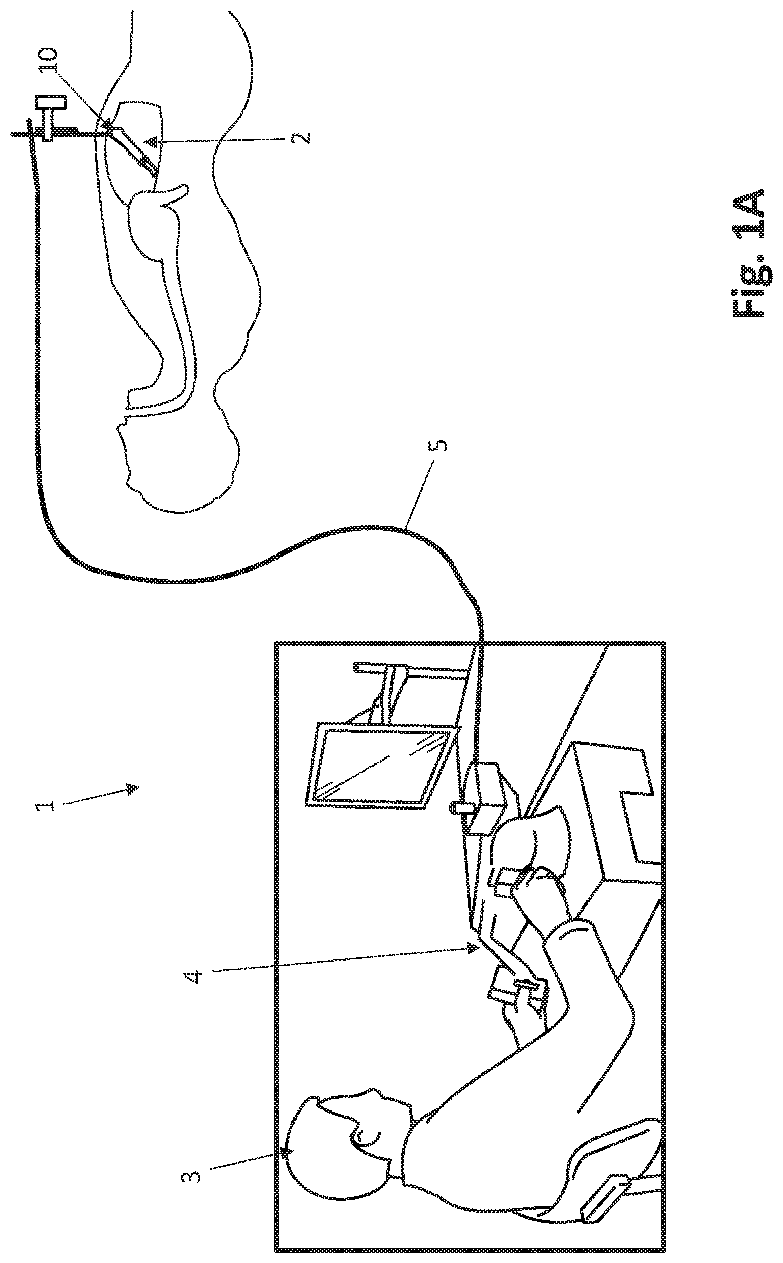
FIG. 1A is a diagram showing a robotic surgical system, including a robotic device positioned inside a body, according to one embodiment.
FIG. 1B is a perspective view of the device of FIG. 1A.
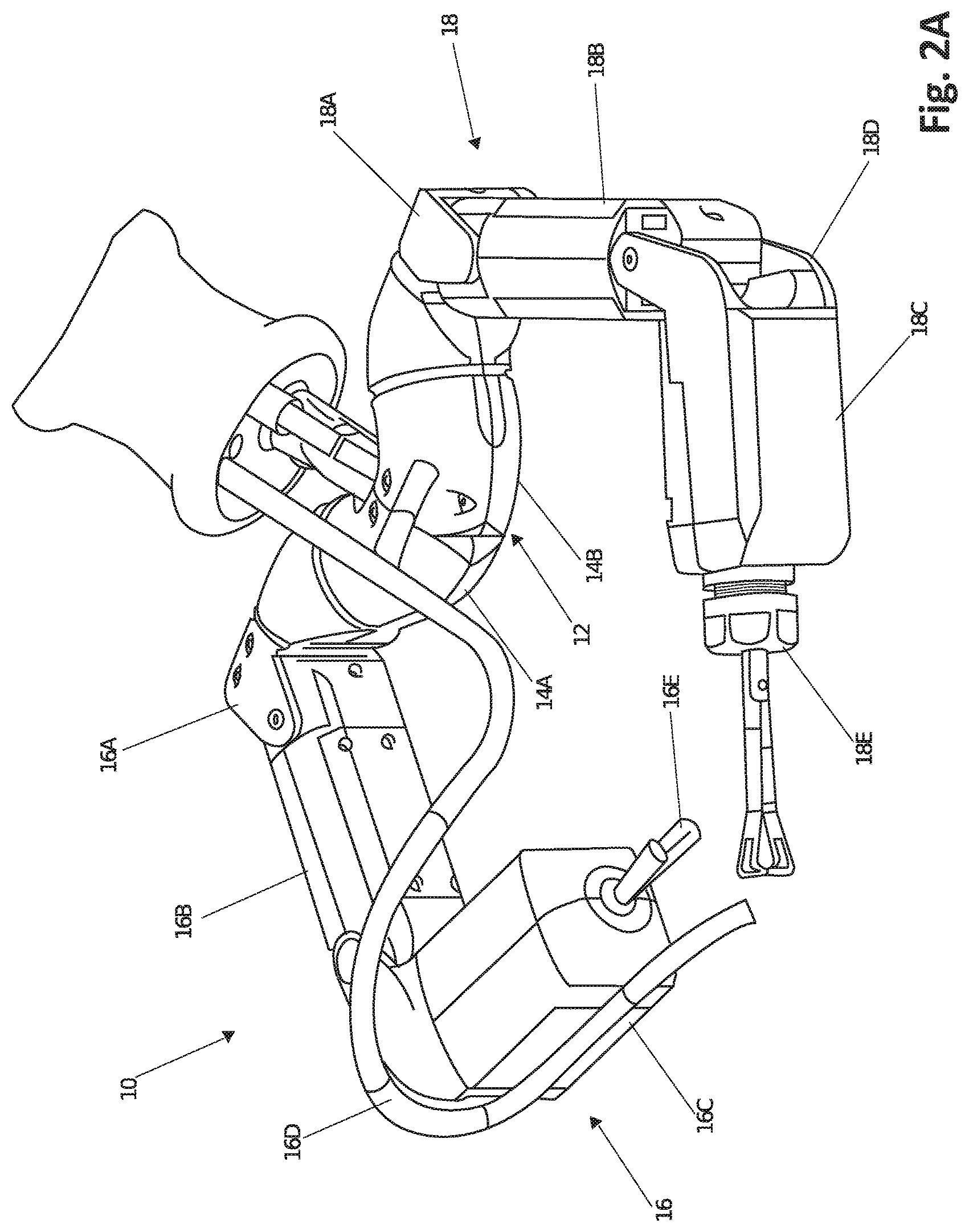
FIG. 2A is a perspective view of a robotic medical device, according to one embodiment.
FIG. 2B is a perspective view of a robotic medical device showing the axes of rotation, according to one embodiment.
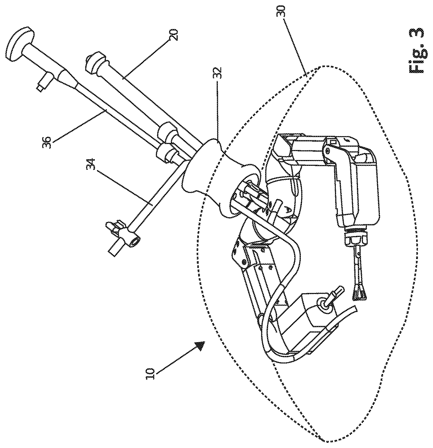
FIG. 3 is a perspective view of a robotic device and related equipment, according to one embodiment.
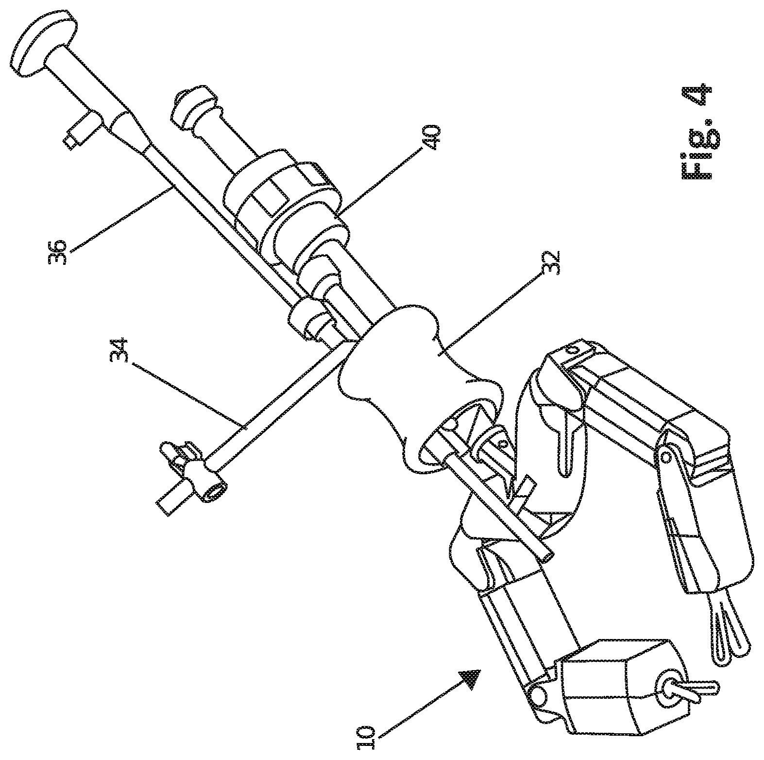
FIG. 4 is a perspective view of a robotic device and related equipment, according to one embodiment.
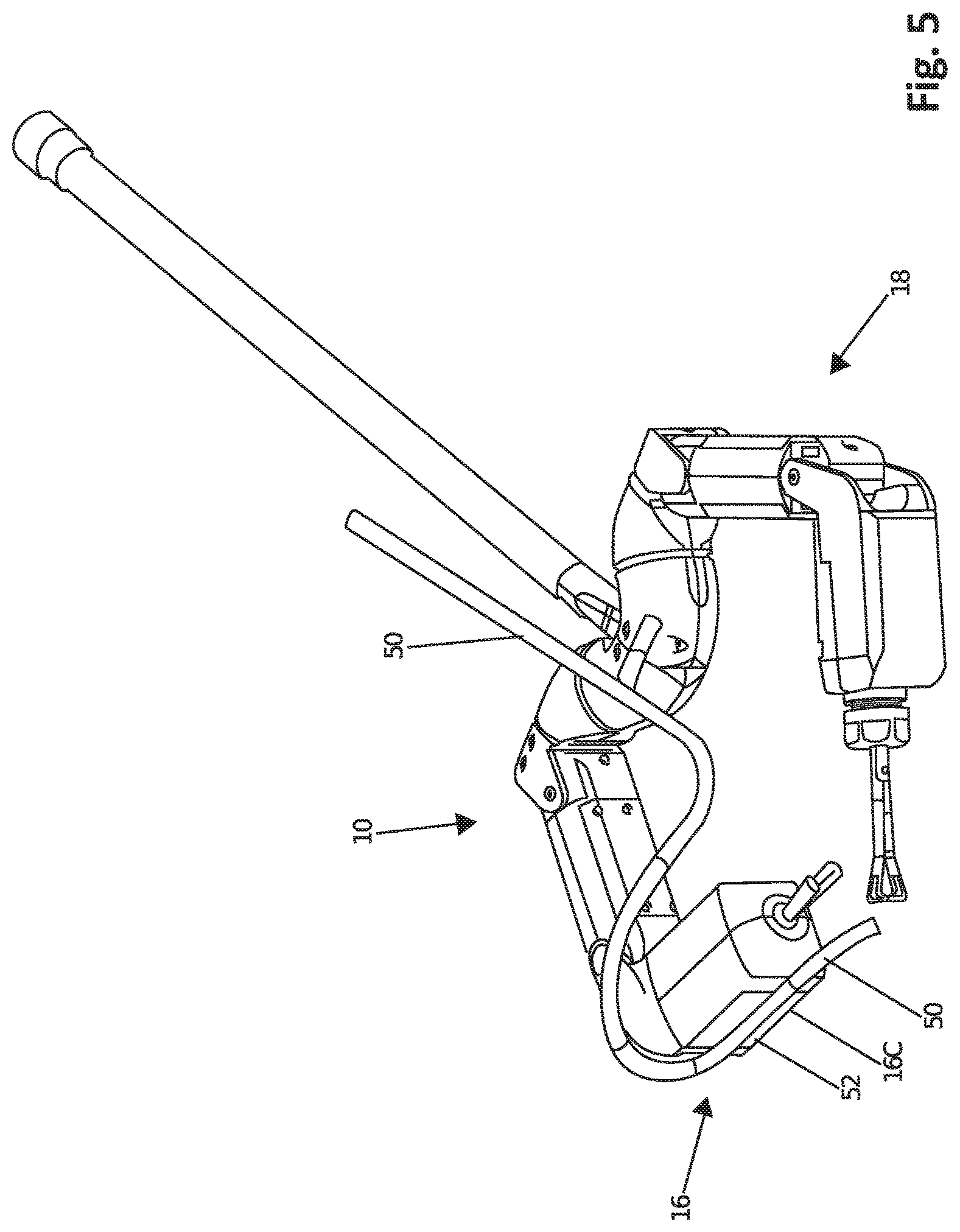
FIG. 5 is a perspective view of a robotic device and related equipment, according to one embodiment.
FIG. 6A is a perspective view of the arm of a robotic device poised to be inserted into a patient's cavity, according to one embodiment.
FIG. 6B is a perspective view of the arm of FIG. 6A, rotated to show an alternate angle.
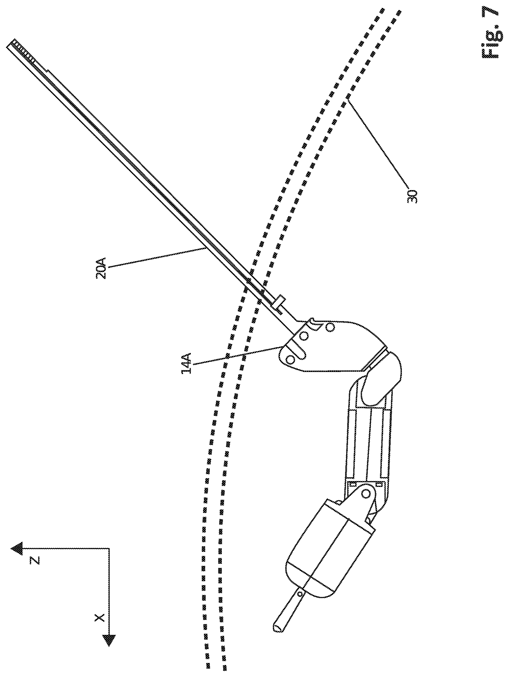
FIG. 7 is a side view of a robotic device during insertion and assembly, according to one embodiment.
FIG. 8 is another perspective view of the robotic device with an overtube for assembly, according to one embodiment.
FIG. 9 is another perspective view of the robotic device during assembly, according to one embodiment.
FIG. 10 is another perspective view of the robotic device and related equipment, according to one embodiment.
FIG. 11 is a view of a robotic device and related equipment, according to one embodiment.
FIG. 12A is a perspective view of a robotic medical device, according to one embodiment.
FIG. 12B is a cutaway perspective view of a robotic medical device, according to one embodiment.
FIG. 12C is a perspective view of a printed circuit board of a robotic medical device, according to one embodiment.
FIG. 12D is a cutaway perspective view of a robotic medical device, according to one embodiment.
FIG. 13A is a side cutaway view of a robotic medical device, according to one embodiment.
FIG. 13B is a front view of a forearm of a robotic medical device, according to one embodiment.
FIG. 13C is a rear perspective view of a forearm of a robotic medical device, according to one embodiment.
FIG. 13D is cutaway perspective view of a forearm of a robotic medical device, according to one embodiment.
FIG. 14 shows a cut away view of a robotic forearm, according to one embodiment.
FIG. 15A shows a cutaway side view of a robotic upper arm, according to one embodiment.
FIG. 15B shows an end view of a robotic upper arm, according to one embodiment.
FIG. 15C shows a perspective view of a robotic upper arm, according to one embodiment.
FIG. 15D shows a cutaway perspective view of a robotic upper arm, according to one embodiment.
FIG. 16A shows a cutaway side view of a robotic shoulder, according to one embodiment.
FIG. 16B shows an end view of a robotic shoulder, according to one embodiment.
FIG. 16C shows a perspective view of a robotic shoulder, according to one embodiment.
FIG. 16D shows a perspective cutaway view of a robotic shoulder, according to one embodiment.
FIG. 17A shows a top cutaway view of robotic device cabling, according to one embodiment.
FIG. 17B shows a cutaway perspective view of robotic device circuit boards, according to one embodiment.
FIG. 18 shows a block diagram of electronics for a robotic device/arm, according to one embodiment.
FIG. 19 shows a block diagram of electronics for a robotic device/arm, according to one embodiment.
FIG. 20A shows a robotic arm according to one embodiment.
FIG. 20B shows a robotic arm sleeve mold, according to one embodiment.
FIG. 21A shows a robotic arm and sleeve making process overview, according to one embodiment.
FIG. 21B shows a robotic arm and sleeve making process overview, according to one embodiment.
FIG. 22A shows the rolled edge of the protective sleeve and the sleeve placed on the robotic arm, according to one embodiment.
FIG. 22B shows the robotic arm, according to one embodiment.
DETAILED DESCRIPTION
The various systems and devices disclosed herein relate to devices for use in medical procedures and systems. More specifically, various embodiments relate to various medical devices, including robotic devices and related methods and systems.
It is understood that the various embodiments of robotic devices and related methods and systems disclosed herein can be incorporated into or used with any other known medical devices, systems, and methods.
For example, the various embodiments disclosed herein may be incorporated into or used with any of the medical devices and systems disclosed in copending U.S. application Ser. No. 12/192,779 (filed on Aug. 15, 2008 and entitled "Modular and Cooperative Medical Devices and Related Systems and Methods"), U.S. Pat. No. 7,492,116 (filed on Oct. 31, 2007 and entitled "Robot for Surgical Applications"), U.S. Pat. No. 7,772,796 (filed on Apr. 3, 2007 and entitled "Robot for Surgical Applications"), Ser. No. 11/947,097 (filed on Nov. 27, 2007 and entitled "Robotic Devices with Agent Delivery Components and Related Methods"), Ser. No. 11/932,516 (filed on Oct. 31, 2007 and entitled "Robot for Surgical Applications"), Ser. No. 11/766,683 (filed on Jun. 21, 2007 and entitled "Magnetically Coupleable Robotic Devices and Related Methods"), Ser. No. 11/766,720 (filed on Jun. 21, 2007 and entitled "Magnetically Coupleable Surgical Robotic Devices and Related Methods"), Ser. No. 11/966,741 (filed on Dec. 28, 2007 and entitled "Methods, Systems, and Devices for Surgical Visualization and Device Manipulation"), Ser. No. 12/171,413 (filed on Jul. 11, 2008 and entitled "Methods and Systems of Actuation in Robotic Devices"), 60/956,032 (filed on Aug. 15, 2007), 60/983,445 (filed on Oct. 29, 2007), 60/990,062 (filed on Nov. 26, 2007), 60/990,076 (filed on Nov. 26, 2007), 60/990,086 (filed on Nov. 26, 2007), 60/990,106 (filed on Nov. 26, 2007), 60/990,470 (filed on Nov. 27, 2007), 61/025,346 (filed on Feb. 1, 2008), 61/030,588 (filed on Feb. 22, 2008), 61/030,617 (filed on Feb. 22, 2008), U.S. Pat. No. 8,179,073 (issued May 15, 2011, and entitled "Robotic Devices with Agent Delivery Components and Related Methods"), Ser. No. 12/324,364 (filed Nov. 26, 2008, U.S. Published App. 2009/0171373 and entitled "Multifunctional Operational Component for Robotic Devices"), and Ser. No. 13/493,725 (filed Jun. 11, 2012 and entitled "Methods, Systems, and Devices Relating to Surgical End Effectors"), all of which are hereby incorporated herein by reference in their entireties.
Certain device and system implementations disclosed in the applications listed above can be positioned within a body cavity of a patient in combination with a support component similar to those disclosed herein. An "in vivo device" as used herein means any device that can be positioned, operated, or controlled at least in part by a user while being positioned within a body cavity of a patient, including any device that is coupled to a support component such as a rod or other such component that is disposed through an opening or orifice of the body cavity, also including any device positioned substantially against or adjacent to a wall of a body cavity of a patient, further including any such device that is internally actuated (having no external source of motive force), and additionally including any device that may be used laparoscopically or endoscopically during a surgical procedure. As used herein, the terms "robot," and "robotic device" shall refer to any device that can perform a task either automatically or in response to a command.
Certain embodiments provide for insertion of the present invention into the cavity while maintaining sufficient insufflation of the cavity. Further embodiments minimize the physical contact of the surgeon or surgical users with the present invention during the insertion process. Other implementations enhance the safety of the insertion process for the patient and the present invention. For example, some embodiments provide visualization of the present invention as it is being inserted into the patient's cavity to ensure that no damaging contact occurs between the system/device and the patient. In addition, certain embodiments allow for minimization of the incision size/length. Further implementations reduce the complexity of the access/insertion procedure and/or the steps required for the procedure. Other embodiments relate to devices that have minimal profiles, minimal size, or are generally minimal in function and appearance to enhance ease of handling and use.
Certain implementations disclosed herein relate to "combination" or "modular" medical devices that can be assembled in a variety of configurations. For purposes of this application, both "combination device" and "modular device" shall mean any medical device having modular or interchangeable components that can be arranged in a variety of different configurations. The modular components and combination devices disclosed herein also include segmented triangular or quadrangular-shaped combination devices. These devices, which are made up of modular components (also referred to herein as "segments") that are connected to create the triangular or quadrangular configuration, can provide leverage and/or stability during use while also providing for substantial payload space within the device that can be used for larger components or more operational components. As with the various combination devices disclosed and discussed above, according to one embodiment these triangular or quadrangular devices can be positioned inside the body cavity of a patient in the same fashion as those devices discussed and disclosed above.
FIGS. 1A and 1B depict an exemplary system 1 that includes a robotic surgical device 10 disposed within the inflated peritoneal cavity 2 of a patient. It is understood that the various device and system embodiments disclosed herein, including the system 1 of FIGS. 1A and 1B, can be used for a variety of surgical procedures and tasks including, but not limited to, tissue biopsy, tissue dissection, or tissue retraction. For example, as shown in FIGS. 1A and 1B in accordance with one embodiment, the device 10 can be used to dissect tissue in the peritoneal cavity 2. In this system embodiment, a user (such as, for example, a surgeon) 3 operates a user interface 4 to control the device 10. The interface 4 is operably coupled to the device 10 by a cable 5 or other type of physical connection that provides for electronic power and/or electrical communication back and forth between the interface 4 and the device 10. Alternatively, the interface 4 can be operably coupled to the device 10 wirelessly. It is understood that the device embodiments disclosed herein can also be used with any other known system, including any of the systems disclosed in the various patent applications incorporated by reference above and elsewhere herein.
FIG. 2A depicts a robotic medical device 10, in accordance with one implementation. According to one embodiment, the device is an in vivo device. This device 10 embodiment as shown includes a body 12 that has two components 14A, 14B, which in this embodiment are cylindrical components 14A, 14B at an approximately 120 degree angle to each other. The cylindrical components 14A, 14B can also be referred to herein as shoulders, including a right shoulder 14A and a left shoulder 14B. In the embodiment depicted in FIG. 2A, the two components 14A, 14B are coupled directly to each other. Alternatively, the two components are not coupled to each other or, in another option, can be individually coupled to an access port used in the surgery. In a further alternative, the body 12 (and any body of any device embodiment disclosed herein) can be a single component and further can be any of the device body embodiments disclosed in the various patent applications incorporated by reference above and elsewhere herein.
The body 12 is connected to two arms 16, 18 in one example of the device. In the implementation shown, the right shoulder 14A is coupled to right arm 16 and left shoulder 14B is coupled to left arm 18. In addition, the body 12 is also coupled to a support component 20, as best shown in FIG. 8. In accordance with one implementation as shown in FIGS. 6A and 6B and described in additional detail below, the support rod 20 as configured is a support rod 20 that is made of two coupleable support rod components 20A, 20B, each of which is independently attached to one of the body components 14A, 14B. More specifically, the support component 20 has a first support rod component 20A that is coupled to the first shoulder 14A and a second support rod component 20B that is coupled to the second shoulder component 14B. Alternatively, the support component 20 can be a single, integral component coupled to the body 12. In certain implementations, the support component 20 can be a rod, tube, or other applicable shape.
Returning to FIG. 2A, each of the arms 16, 18 have a first joint 16A, 18A (each of which can also be referred to as a "shoulder joint") that is coupled to the body components 14A, 14B. Each first joint 16A, 18A is coupled to a first link 16B, 18B (also referred to as a "first segment," an "upper segment," or an "upper arm"), each of which is rotatably coupled to a second link 16C, 18C (also referred to as a "second segment," a "lower segment," or a "forearm") via a second joint 16D, 18D (each of which can also be referred to as an "elbow joint"). In addition, each arm 16, 18 also has an operational component (also referred to as an "end effector") 16E, 18E coupled to the forearm 16C, 18C. It is understood that the operational components 16E, 18E (and any of the operational components on any of the embodiments disclosed herein) can be any known operational components, including any of the operational components disclosed in the various patent applications incorporated by reference above and elsewhere herein. By way of example, the components 16E, 18E can be cautery devices, suturing devices, grasping devices, imaging devices, operational arm devices, sensor devices, lighting devices or any other known types of devices or components for use in surgical procedures.
As mentioned above and as shown in FIG. 2B, the first links 16B, 18B are coupled to the body 12 via shoulder joints 16A, 18A. In one embodiment, each shoulder joint 16A, 16B is a joint having two axes of rotation. For example, as will be described in further detail below, the left shoulder joint 18A can be configured to result in rotation of the upper arm 18B as shown by arrow A around axis AA (that substantially corresponds to the longitudinal axis of the body 12) and also as shown by arrow B around axis BB, which is substantially perpendicular to axis AA. Because right shoulder joint 16A and right upper arm 16B are substantially the same as the left shoulder joint 18A and the left upper arm 18B, the above description also applies to those substantially similar (or identical) components. Alternatively, any known joint can be used to couple the upper arms 16B, 18B to the body 12.
Continuing with FIG. 2B, the upper arms 16B, 18B, according to one implementation, are coupled to the forearms 16C, 18C, respectively, at the elbow joints 16D, 16D such that each of the forearms 16C, 18C can rotate. For example, the forearms 16C, 18C can rotate as shown by arrow C around axis CC. Further, the end effectors 16E, 18E can also rotate relative to the forearms 16C, 18C, respectively, as shown by arrow D around axis DD. In addition, each of the operational components 16E, 18E can also be actuated to move between at least two configurations, such as an open configuration and a closed configuration. Alternatively, the operational components 16E, 18E can be coupled to the forearms 16C, 18C, respectively, such that the operational components 16E, 18E can be moved or actuated in any known fashion.
According to one embodiment, the operational components 16E, 18E, such as graspers or scissors, are also removable from the forearms 16C, 18C, such that the operational components 16E, 18E are interchangeable with other operational components configured to perform other/different types of procedures. Returning to FIG. 2A, one operational component 16E is a grasper 16E commonly known as a babcock grasper and the other 18E is a vessel sealing grasper 18E. Alternatively, either or both of the components 16E, 18E can be cautery devices, suturing devices, grasping devices, or any other known types of devices or components for use in surgical procedures, or can be easily replaced with such components.
It is understood that the device 10 in this embodiment contains the motors (also referred to as "actuators," and intended to include any known source of motive force) that provide the motive force required to move the arms 16, 18 and the operational components 16E, 18E. In other words, the motors are contained within the device 10 itself (either in the body, the upper arms, the forearms or any and all of these), rather than being located outside the patient's body. Various motors incorporated into various device embodiments will be described in further detail below.
In use, as in the example shown in FIG. 3, the device 10 is positioned inside a patient's body cavity 30. For example, in FIG. 3, the body cavity 30 is the peritoneal cavity 30.
According to one implementation, the device 10 can be sealed inside the insufflated abdominal cavity 30 using a port 32 designed for single incision laparoscopic surgery. Alternatively, the device 10 can be inserted via a natural orifice, or be used in conjunction with other established methods for surgery. The device 10 is supported inside the abdominal cavity using the support rod 20 discussed above. The laparoscopic port 32 can also be used for insertion of an insufflation tube 34, a laparoscope 36 or other visualization device that may or may not be coupled to the device assembly. As an example, a 5 mm laparoscope 36 is shown in FIG. 3.
Alternatively, as shown in FIG. 4, a cannula or trocar 40 can be used in conjunction with the port device 32 to create a seal between the cavity and the external environment. Alternatively, any other known surgical instrument designed for such purposes can be used in conjunction with the port device 32 to create a seal between the cavity and the external environment, as is discussed below with regard to FIG. 9.
According to one alternative embodiment as shown in FIG. 5, a suction/irrigation tube 50 can be coupled with the device 10 and used for surgical suction and/or irrigation. In this embodiment, the tube 50 is coupled to the forearm 16C of the right arm 16. More specifically, the forearm 16C has a channel 52 defined on an exterior surface of the forearm 16C that is configured to receive and removably hold the tube 50. In use, the tube 50 can extend from the device 10 and through an orifice to an external device or system for use for surgical suction and/or irrigation. Alternatively, the tube 50 can be coupled to the left arm 18 or some other portion of the device 10. In a further alternative, the tube 50 can be disposed internally within the arm 16 or other component of the device 10.
In use, the device 10 can first be separated into the two smaller components as described above and then each of the two components are inserted in consecutive fashion through the orifice into the body cavity. In accordance with one implementation, due to the limitations associated with the amount of space in the cavity, each of the components can form a sequence of various configurations that make it possible to insert each such component into the cavity. That is, each component can be "stepped through" a sequence of configurations that allow the component to be inserted through the orifice and into the cavity.
For example, according to one implementation shown in FIGS. 6A and 6B, the device 10 can be inserted through a single orifice by physically separating the device 10 into separate, smaller components and inserting those components through the single orifice. In one example, the device can be separated into two "halves" or smaller components, in which one half 10A as shown in FIGS. 6A and 6B consists of the right shoulder 14A coupled to the right arm 16. Similarly, while not depicted in FIGS. 6A and 6B, the other half consists of the left shoulder 14B coupled to the left arm 18. It is understood that the left arm 18 is substantially similar to or the same as the right arm 16 such that the description of the right arm herein and the depiction in FIGS. 6A and 6B apply equally to the left arm 18 as well. In this implementation, the right shoulder 14A is coupled to the right support rod component 20A (and the left shoulder 14B is similarly coupled to the left support rod component 20B). Alternatively, this device 10 or any device contemplated herein can be separated into any two or more separable components.
FIGS. 6A and 6B show how the right support component 20A can be rotationally coupled to the shoulder 14A, thereby resulting in movement of the shoulder 14A in relation to the right support component 20A between at least two configurations, making insertion of the overall device into a patient's cavity easier. More specifically, the right device half 10A is shown in FIG. 6A in its operational configuration in relation to the right support component 20A such that the right device half 10A can be coupled to the left device half 10B (not shown) and thereby used to perform a procedure in the patient's cavity. Note the arrow 21 in FIG. 6A illustrating how the right support component 20A can rotate in relation to the right shoulder 14A. FIG. 6B, on the other hand, depicts the right device half 10A in its insertion configuration in which the right shoulder 14A has been rotated in relation to the right support component 20A, thereby making the device half 10A easier to insert through an orifice and into a patient's cavity. In use, the device half 10A is "stepped through" the two configurations to ease insertion. First, the device half 10A is placed in the insertion configuration of FIG. 6B and inserted through the orifice. Subsequently, once the right arm 16 is positioned inside the patient's cavity, the right shoulder 14A can be rotated in relation to the right support component 20A to move the device half 10A into the operational configuration of FIG. 6A such that the device half 10A can be coupled to the other half 10B and subsequently be used to perform a procedure.
When the device half 10A is properly positioned in the patient's cavity, the first support rod component 20A, which is coupled to the right shoulder 14A, is disposed through an orifice or any other kind of opening in the body cavity wall (shown as a dashed line in FIG. 7) such that the distal portion of the support rod component 20A coupled to the first shoulder 14A is disposed within the body cavity 30 while the proximal portion is disposed outside of the patient's body and can be attached to an external component (not shown) so as to provide stability or fixed positioning for the device.
As discussed above, in this example, the two coupleable support rod components (such as 20A as shown in FIGS. 6A, 6B, and 7) can be positioned next to one another or coupled to each other form a cylindrical shape or a complete rod 20. In the example in FIG. 8, an overtube 60 can then be placed over the rod 20. As best shown in FIG. 9, this overtube 60 can be held in place with a threaded thumbscrew 61 and the entire rod 20 and overtube 60 assembly can then be inserted into the laparoscopic port 32. As best shown in FIG. 10, once assembled, other tools can then be inserted into the port such as a cannula for a suction/irrigation tube 34 as described above, a laparoscope 36 as described above, and/or other surgical instruments, and positioned through the port 32 via port openings 32A, 32B, 32C (as best shown in FIG. 9). These figures illustrate one example of how this assembly can be configured to accept a cannula for suction and irrigation or other component 33.
Alternatively, the device body 10 can be a single component that is coupled to both support rod components 20A, 20B, which are coupled to each other to form a full support rod 20.
Once assembled, an external device (not shown) can be used to stabilize the support component assembly. According to this implementation, the device 10 is maintained in a desired position or location within the body cavity of the patient using an external component that has a clamp that is removably attached to the support component 20. Alternatively, the external component can have any known attachment component that is capable of removably coupling to or attaching to support component.
As an example, the external component can be an iron intern (commercially available from Automated Medical Products Corp.) that includes several sections connected by joints that can be loosened and locked using knobs to allow the iron intern to be positioned in various orientations. The iron intern can be attached to rails on any standard surgical table or any other appropriate surface to provide support for device.
In use, according to one embodiment, the device 10 is positioned within the body cavity of the patient and the support component assembly 20 is positioned through a port 32 positioned in the hole or opening in the body cavity wall, as shown, for example, in FIG. 3. In one embodiment, the port 32 is a gel port through which the support component 20 can be disposed while still maintaining a fluidic seal that allows for the body cavity 30 of the patient to be inflated. Alternatively, any known port 32 that provides access for the support component 20 while maintaining a fluidic seal can be used. Also, any cables, electrical or otherwise, can be coupled to the device 10 via this port 32. In one embodiment, electrical cables pass through the support rod 20 or other support components.
FIG. 11 depicts one example of how a laparoscope 36 in one embodiment can be used in conjunction with the device 10 to provide visualization of the working space of the robotic assembly. More specifically, FIG. 11 shows how a "zero degree" laparoscope 36 can provide a large field of view (shown as cone 70) enabling the user to view the surgical environment. Other visualization means are also possible and these can either be separate from or attached to the robotic device 10. The visualization means can also enter though other orifices in the body cavity to be used independently or in conjunction with the robotic device 10.
FIGS. 12A-17 depict exemplary embodiments of how such a medical device can be mechanically and electrically constructed.
FIGS. 12A-12D show one design of a forearm 80 having a vessel sealing operational component or end effector 82. The vessel sealing device 82 may or may not include a cutting component and different types of cautery techniques. In this example, as best shown in FIGS. 12B and 12D, a first actuator 84 is coupled to the end effector 82 by spur gears 84A, a second actuator 86 is coupled to the end effector 82 by spur gears 86A, and a third actuator 88 is coupled to the end effector by spur gears 88A. These first, second and third actuators 84, 86, 88 provide rotation of the end effector 82 along the axis of the forearm 80 (axis DD as described in FIG. 2), opening and closing motion for the end effector 82, and can cause a cutting device (not shown) to translate through the end effector 82.
FIGS. 12A-17 also show various printed circuit boards 114A-114J used to power and control the actuators. Each actuator has one or more sensors to measure the position of the components for control. These can include, but are not limited to, optical encoders, mechanical encoders, or potentiometers. Each sensor can either measure relative or absolute position.
FIGS. 13A-13D depict another embodiment of a forearm 90 for a robotic medical device. This embodiment shows an interchangeable operational component 92, which, in this specific example, is a grasper 92 commonly called a Babcock grasper. These interchangeable operational components can be similar to the interchangeable tools called Microline made by the Pentax Company. In this embodiment, as best shown in FIGS. 13B and 13C, the interchangeable tools are held in place using a known tapered collect device 94 (commonly used in machine tools) to hold the operational component in place. Here, the operational component is inserted into a tapered collect 94 that is then tightened in place using a threaded nut and a tapered slot 96. In this example, as best shown in FIG. 13D, there are two actuators 97, 98 that actuate open and closing of the operating component and rotation of the operating component (about axis DD as described above) by way of corresponding spur gears 97A, 98A with respect to the forearm 90. In this design, as an example, the operational component can be electrified for either mono-polar or bipolar cautery.
FIG. 14 shows how a fuse clip 100, or similar sliding contact device, can be used to provide an electrical connection to one or more portions of the operational component (not shown) to provide electricity for cautery. For example, as shown in the figure, the fuse clip 100 is coupled to a shaft 102 which may spin or rotate, the fuse clip 100 acting to maintain electrical connectivity to the shaft 102 for supply to the operational component (not shown) for cautery without the use of wires that may tangle and bunch. FIG. 14 also shows a printed circuit board (PCB) 114 that contains electronics to power and control the actuators as described previously. More specifically, in this particular figure, the PCB 114 is coupled to the actuator (not shown) such that it may control the electrification of the shaft 102 and ultimately the operational component (not shown).
FIGS. 15A-15D show one possible upper arm segment 16B embodiment. This segment 16B has two actuators 104, 106 that provide rotation of the forearm segment relative to the upper arm 16B and the upper arm 16B relative to the body 14, as described, for example, as axis CC and axis BB in FIG. 3, respectively. In this design, the two actuators 104, 106 are operably coupled to bevel gears 104A, 106A by way of drive gears 104B, 106B to change the axis of rotation of the motors 104, 106 by ninety degrees and make the two axes of rotation (CC & BB) perpendicular to the axes of the segment 16B. Also shown are the sensors and electronics used to control the segment 16B as described above.
FIGS. 16A-16D show one possible device body segment 14A embodiment. Here, an actuator 110 is coupled to the output shaft 112 by bevel gears 113A, 113B such that the axis of actuator 110 rotation is approximately 30 degrees from the axis of rotation of the output shaft 112. Also shown are the sensors and electronics used to control the actuator 110 in the body segment 14A in a fashion similar to that described above.
FIGS. 17A and 17B depict one possible implementation of a device 10 having printed circuit boards 114A-J and connective electrical cables 116A-J that are contained and routed inside the device 10 to provide electrical power and control. More specifically, FIG. 17A depicts the cables 116A-116J and FIG. 17B depicts the PCBs 114A-114J. In this example, "service loops" are provided at each joint to allow for relative motion between the links while not placing the cables in excessive bending or tension (not shown). Alternatively, the circuit boards and cabling can be positioned outside the robot.
FIG. 18 shows a general schematic for one possible design of the electrical sub-system of a robotic device in accordance with one embodiment. The schematic shows an example of the electronics for a vessel sealing arm, such as, for example, the right arm in the robot 10 depicted in FIGS. 2A and 2B. In this example as shown schematically in FIG. 18, the connection cable 122 enters through the support rod 120. This cable 122 can contain conductors for electrical power and electrical signals and other wires of various forms as required for operation of the device 10. This cable 122 interfaces with the shoulder pitch PCB 124. This shoulder pitch PCB 124 supports both an optical encoder 126 and a magnetic encoder 128 for redundant measurement of rotation of the first shoulder joint 18A (around axis AA) as shown in FIGS. 2A and 2B. This PCB 124 provides power to the shoulder pitch motor 128 (for rotation around axis AA). It can also be seen that the cable 122 (via connectors J1 and J2) passes via a service loop 130 into the main joint 18B (described as the upper arm above). Here a "service loop" 130A, 130B, 130C, 130D, 130E is provided at each joint to allow for relative motion between the links while not placing the cables in excessive bending or tension.
The shoulder pitch PCB is also connected to the upper arm via a service loop 130B and connectors (J3 & J4). In the upper arm 18B there is an upper arm shoulder PCB 132 (for axis BB in FIG. 2B) and an upper arm elbow PCB 134 (for axis CC). This link also has internal connectors J5 & J6. All connectors generally aid and allow for assembly and repair. Both PCBs 132, 134 in this link power an actuator 136, 138 for each joint (axis BB & CC) as well as both optical 140, 142 and magnetic 144, 146 encoders to measure joint position. The sensors in this arm and throughout the robot can be used redundantly and or individually or in combination. They can be either relative or absolute or in any combination. There are also connections from the upper arm to the lower arm via connectors listed as J7, J8, J18 & J19 and via service loops.
Here and throughout the robot service loops may or may not be required. The forearm contains three PCBs 150, 152, 154 to drive/control the gripper cutting device 154A, the gripper jaws 152A and the gripper roll 150A (axis DD). As before various sensors 156 and motors 150A, 152A, 154A are powered and used with the PCBs and various service loops 130C, 130D, 130E are used. As shown previously, the gripper can be electrified for cautery with one or more clips or connectors (or with a direct connection) that may or may not allow relative motion of the gripper jaws (axis DD). This example design shows a PCB for each joint. Alternatively a PCB could be used for each link, or each arm, or any combination of the above. The description above and shown in FIG. 21 is just one example of the electrical design that is possible.
FIG. 19 shows a general schematic for yet another possible design of the electrical sub system of the robotic device. The schematic in FIG. 19 shows an example of the electronics for an arm with interchangeable tools, also referred to as the utility arm or left arm 18 in the design of FIGS. 2A-2B. In this example the electronics, PCBs, connectors, and service loops, etc are similar to the schematic described in FIG. 18 but this arm does not have a cutting device and hence does not have on actuator and supporting mechanical and electrical components. Again, as shown previously, the gripper can be electrified for cautery with one or more clips or connectors (or with a direct connection) that may or may not allow relative motion of the gripper jaws (axis DD).
Again, in this version both operating components (vessel sealing and interchangeable Babcock grasper) can be electrified for cautery. In general any and combination of the operating components can be electrified with either no cautery, mono-polar cautery, bi-polar cautery, or other surgical treatment technique.
The robotic surgical device described here can be either single use and be designed to be disposed of after its use, or can be made so it can be re-used and sterilized between uses. In one embodiment, to ease cleaning of the device between uses, a protective sleeve is disclosed here that covers the majority of the outer surfaces of the robotic device.
According to one embodiment, shown in FIGS. 20A-20B, a dip mold pattern 200 (best shown in FIG. 20B) is created with a shape and size that is similar to the robotic arm 202 (best shown in FIG. 20A) (also called a utility arm or ligisure arm or other arm, for example 16, 18 in FIGS. 2A-2B) for which a protective sleeve is needed. The dip mold pattern 200 is designed in such a way as to be thicker and larger than the arm 202 in specific areas, such as, for example, around the joints 201A-D. This larger size will result in a protective sleeve 200 that is larger in these areas so it will provide slack for the robotic arm 202 to articulate.
Also, according to one embodiment, FIG. 20A shows how features 204A, 204B (or "grooves") are designed into the robotic device 202. In this embodiment, one groove 204A is at the proximal end of the robotic arm 202 and a second 204B is at the distal end of the arm 202. These grooves 204A, 204B are designed so the protective sleeve 200 will form a tight seal and mechanical connection with the robotic arm 202 to make the arm fluidically sealed.
In another embodiment, a mold, grooves, and sleeve could be created at each the proximal and distal ends of the joints so smaller protective sleeves would be created that would only cover the joint areas. Other combinations are also possible. For example one sleeve could cover two proximal joints and a second sleeve could cover a distal joint.
In use according to one embodiment as shown in FIGS. 21A and 21B, the dip mold pattern 200 can be placed into a vat 210 of dip mold material 212. In one embodiment, this mold material 212 could be a latex or similar material. The pattern can then be removed from the vat 210 and the mold material 212 is then cured in a heated oven 213. The process can be repeated to create multiple layers and thereby a thicker sleeve.
When the mold material is cured, according to one embodiment and shown in FIGS. 22A and 22B, the resulting protective sleeve 214 can be trimmed at each end and then the ends can be rolled 216A, 216B. Rolling the ends creates "beads" at both the proximal 216A and distal 216B ends of the protective sleeve. These "beads" 216A, 216B are designed to fit in the grooves 204A, 204B or other external features or contours (shown as an example in FIG. 20) on the robotic device. The sleeve 214 is then removed from the dip mold 200 and placed onto the robotic arm 202. It can be seen how the protective sleeve 214 now covers and protects most or all of the robotic arm 202 (including the moving joints) from fluid ingress during surgery.
While multiple embodiments are disclosed, still other embodiments of the present invention will become apparent to those skilled in the art from the following detailed description, which shows and describes illustrative embodiments of the invention. As will be realized, the invention is capable of modifications in various obvious aspects, all without departing from the spirit and scope of the present invention. Accordingly, the drawings and detailed description are to be regarded as illustrative in nature and not restrictive.
Although the present invention has been described with reference to preferred embodiments, persons skilled in the art will recognize that changes may be made in form and detail without departing from the spirit and scope of the invention.
* * * * *
References
D00000
D00001
D00002
D00003
D00004
D00005
D00006
D00007
D00008
D00009
D00010
D00011
D00012

D00013

D00014

D00015

D00016
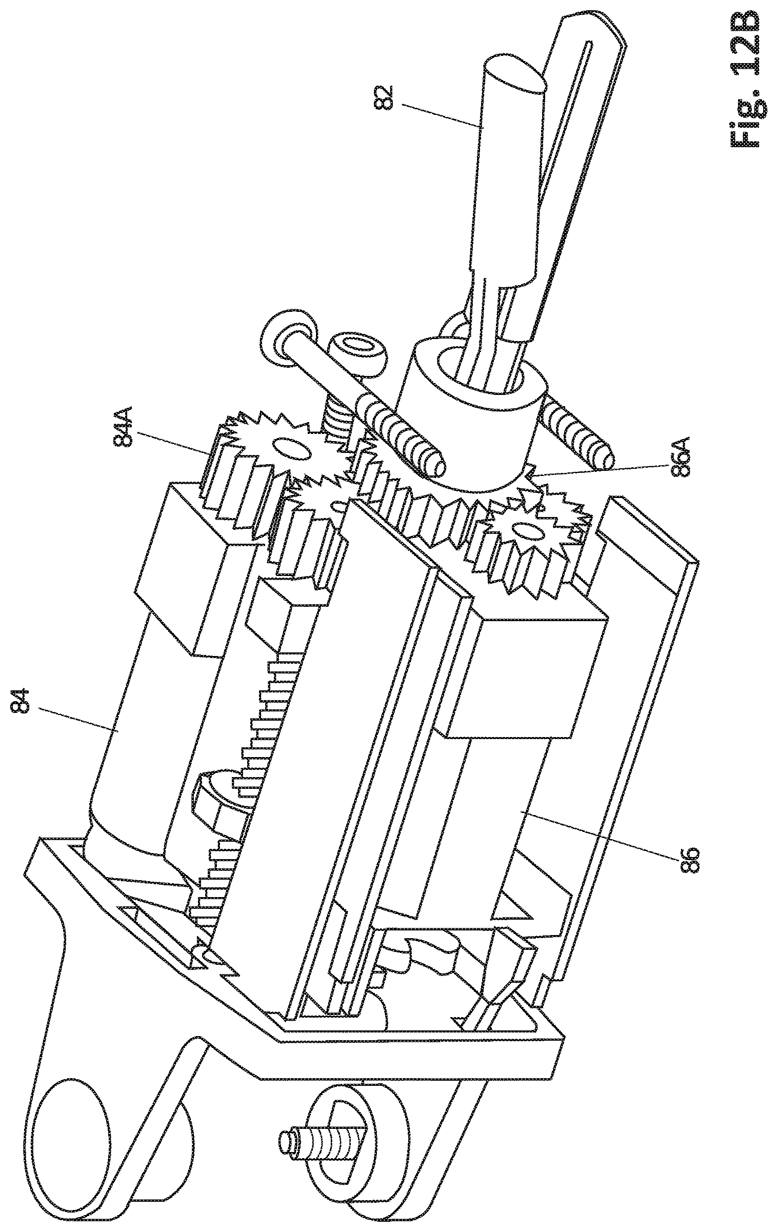
D00017

D00018

D00019

D00020

D00021

D00022

D00023
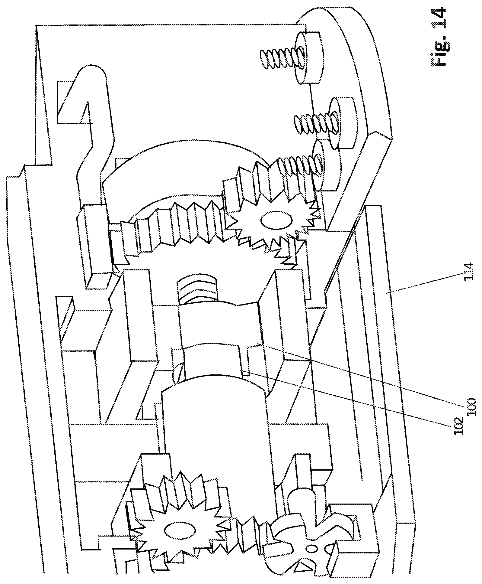
D00024

D00025

D00026

D00027

D00028
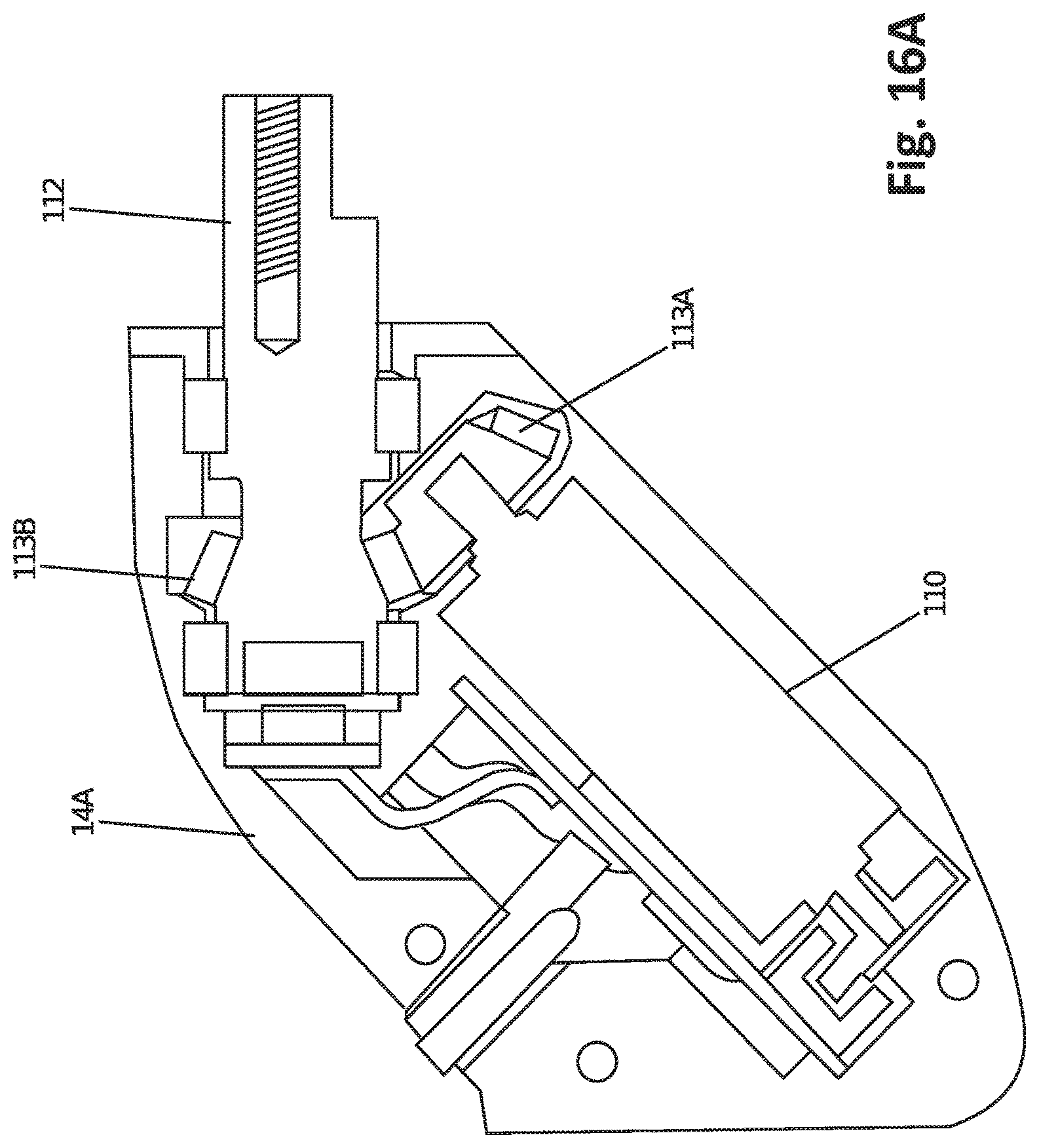
D00029

D00030
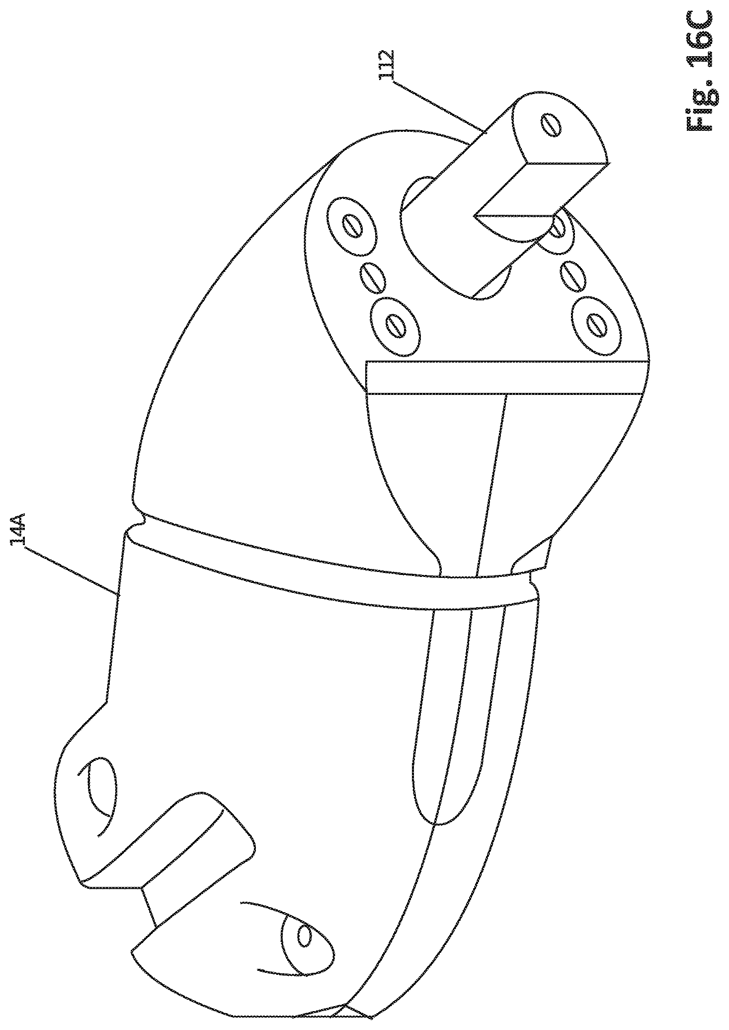
D00031

D00032
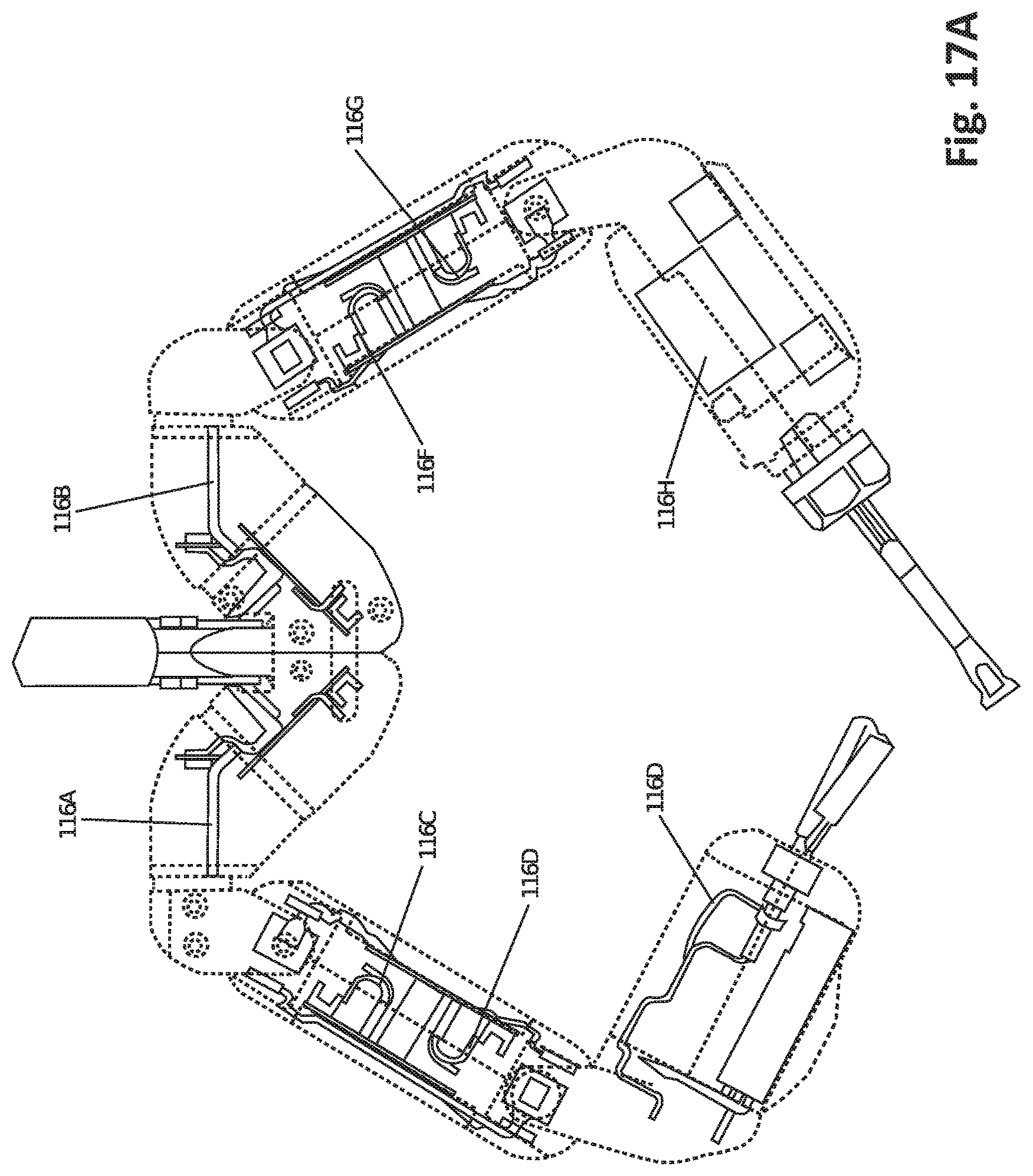
D00033

D00034

D00035

D00036
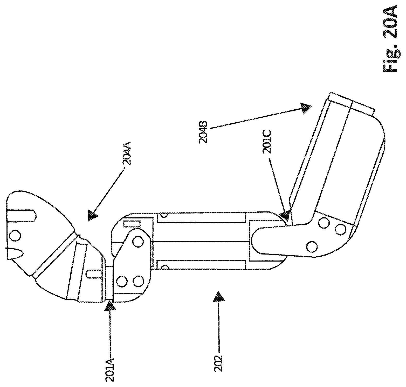
D00037

D00038

D00039

D00040
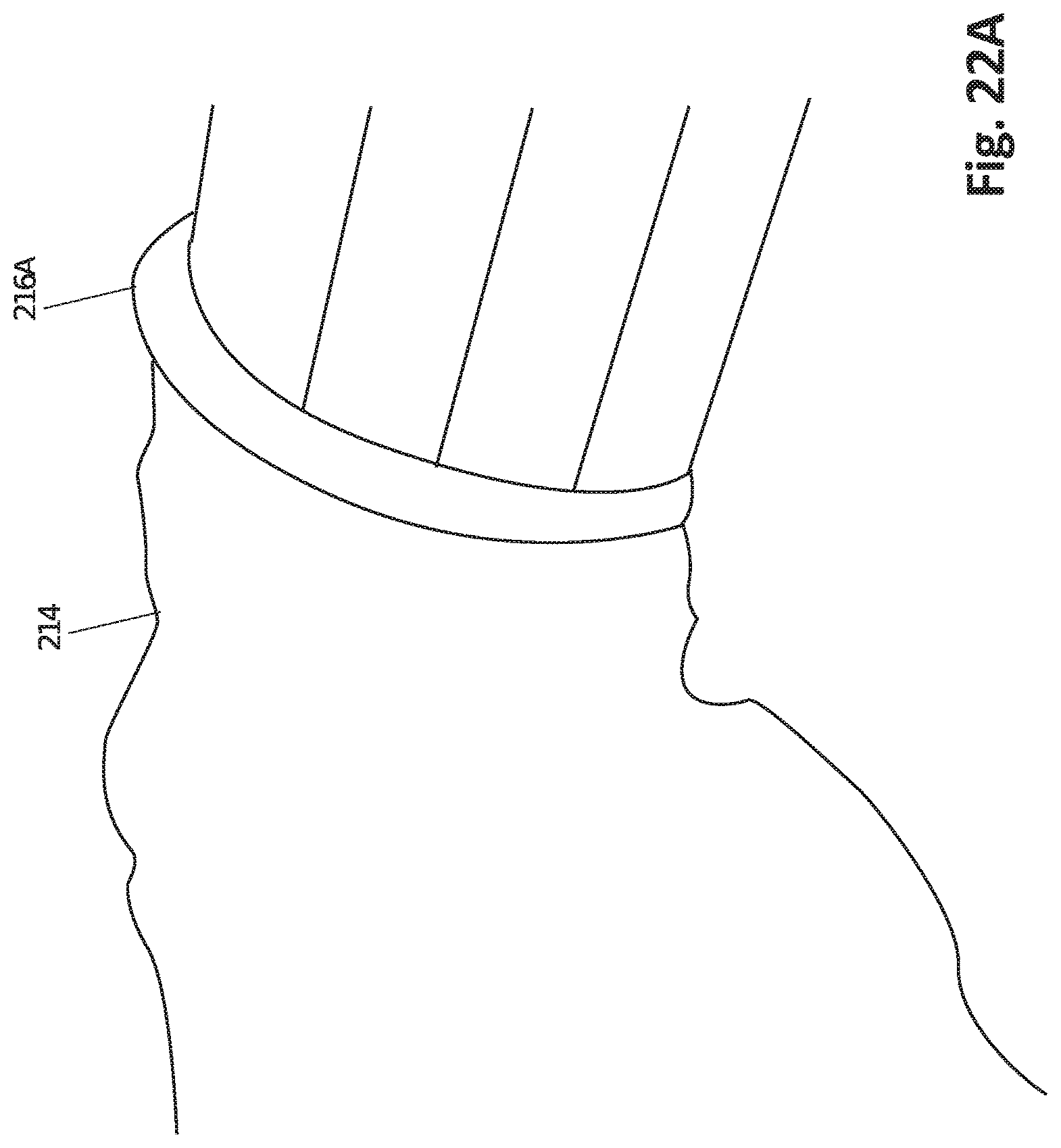
D00041

XML
uspto.report is an independent third-party trademark research tool that is not affiliated, endorsed, or sponsored by the United States Patent and Trademark Office (USPTO) or any other governmental organization. The information provided by uspto.report is based on publicly available data at the time of writing and is intended for informational purposes only.
While we strive to provide accurate and up-to-date information, we do not guarantee the accuracy, completeness, reliability, or suitability of the information displayed on this site. The use of this site is at your own risk. Any reliance you place on such information is therefore strictly at your own risk.
All official trademark data, including owner information, should be verified by visiting the official USPTO website at www.uspto.gov. This site is not intended to replace professional legal advice and should not be used as a substitute for consulting with a legal professional who is knowledgeable about trademark law.