Controlling chilled state of a cargo
Thogersen , et al.
U.S. patent number 10,619,902 [Application Number 15/820,976] was granted by the patent office on 2020-04-14 for controlling chilled state of a cargo. This patent grant is currently assigned to Thermo King Corporation. The grantee listed for this patent is EMERSON CLIMATE TECHNOLOGIES--TRANSPORTATION SOLUTIONS APS, THERMO KING CORPORATION. Invention is credited to Allan Dyrmose, Dan Vad Steffensen, Ole Thogersen.


| United States Patent | 10,619,902 |
| Thogersen , et al. | April 14, 2020 |
Controlling chilled state of a cargo
Abstract
A refrigeration system for use in transport includes a compressor, a condenser, and an evaporator connected in series, an evaporator fan, a supply air temperature sensor, a return air temperature sensor, and a controller. The evaporator fan is configured to discharge supply air from the system to a refrigerated space. The supply air temperature sensor is configured to sense the supply air temperature of the supply air. The return air temperature sensor is configured to sense a return air temperature of return air returning from the refrigerated space to the system. The controller is programmed to determine a requirement for moderate heating and a requirement for increased heating based on the supply air temperature and the return air temperature, to activate the evaporator fan when the requirement for moderate heating is determined, and to increase a speed of the evaporator fan when the requirement for increased heating is determined.
| Inventors: | Thogersen; Ole (Nyborg, DK), Dyrmose; Allan (Bogense, DK), Steffensen; Dan Vad (Spentrup, DK) | ||||||||||
|---|---|---|---|---|---|---|---|---|---|---|---|
| Applicant: |
|
||||||||||
| Assignee: | Thermo King Corporation
(Minneapolis, MN) |
||||||||||
| Family ID: | 41571057 | ||||||||||
| Appl. No.: | 15/820,976 | ||||||||||
| Filed: | November 22, 2017 |
Prior Publication Data
| Document Identifier | Publication Date | |
|---|---|---|
| US 20180164009 A1 | Jun 14, 2018 | |
Related U.S. Patent Documents
| Application Number | Filing Date | Patent Number | Issue Date | ||
|---|---|---|---|---|---|
| 14322541 | Jul 2, 2014 | 9857114 | |||
| 14082299 | Aug 12, 2014 | 8800307 | |||
| 12604003 | Dec 17, 2013 | 8607582 | |||
| 61108090 | Oct 24, 2008 | ||||
| Current U.S. Class: | 1/1 |
| Current CPC Class: | F25B 49/02 (20130101); F25D 11/003 (20130101); F25D 29/003 (20130101); Y02B 30/743 (20130101); F25B 2600/112 (20130101); Y02B 30/70 (20130101); F25B 2700/21173 (20130101); F25B 2700/21172 (20130101); F25B 2400/01 (20130101) |
| Current International Class: | F25B 49/02 (20060101); F25D 29/00 (20060101); F25D 11/00 (20060101) |
References Cited [Referenced By]
U.S. Patent Documents
| 3692100 | September 1972 | Gallagher, Jr. |
| 4137057 | January 1979 | Piet et al. |
| 4357988 | November 1982 | Hudson et al. |
| 4509586 | April 1985 | Watabe |
| 4663725 | May 1987 | Truckenbrod et al. |
| 4787214 | November 1988 | Stillwell |
| 4789025 | December 1988 | Brandemuehl et al. |
| 4790143 | December 1988 | Hanson |
| 4899549 | February 1990 | Berge et al. |
| 4912933 | April 1990 | Renken |
| 4949550 | August 1990 | Hanson |
| 4977752 | December 1990 | Hanson |
| 5065587 | November 1991 | Howland et al. |
| 5123251 | June 1992 | Hanson |
| 5123252 | June 1992 | Hanson et al. |
| 5123253 | June 1992 | Hanson et al. |
| 5140825 | August 1992 | Hanson et al. |
| 5140826 | August 1992 | Hanson et al. |
| 5161383 | November 1992 | Hanson et al. |
| 5161384 | November 1992 | Hanson et al. |
| 5168713 | December 1992 | Howland |
| 5172561 | December 1992 | Hanson et al. |
| 5181389 | January 1993 | Hanson et al. |
| 5186015 | February 1993 | Roehrich et al. |
| 5197670 | March 1993 | Hanson et al. |
| 5201185 | April 1993 | Hanson et al. |
| 5201186 | April 1993 | Hanson |
| 5222368 | June 1993 | Hanson |
| 5226472 | July 1993 | Benevelli et al. |
| 5228301 | July 1993 | Sjoholm et al. |
| 5249429 | October 1993 | Hanson |
| 5295364 | March 1994 | Truckenbrod et al. |
| 5303560 | April 1994 | Hanson et al. |
| 5355692 | October 1994 | Brownfield |
| 5377493 | January 1995 | Friedland |
| 5415006 | May 1995 | Renken et al. |
| 5456088 | October 1995 | Hanson et al. |
| 5557938 | September 1996 | Hanson et al. |
| 5557941 | September 1996 | Hanson et al. |
| 5572879 | November 1996 | Harrington et al. |
| 5579648 | December 1996 | Hanson et al. |
| 5596878 | January 1997 | Hanson et al. |
| 5634347 | June 1997 | Hanson et al. |
| 5669223 | September 1997 | Haley et al. |
| 5711159 | January 1998 | Whipple, III |
| 5778690 | July 1998 | Hanson et al. |
| 6058716 | May 2000 | Reason et al. |
| 6095427 | August 2000 | Hoium et al. |
| 6179212 | January 2001 | Banko |
| 6367269 | April 2002 | Hanson et al. |
| 6560978 | May 2003 | Renken et al. |
| 6584785 | July 2003 | Karl |
| 6609388 | August 2003 | Hanson |
| 6679074 | January 2004 | Hanson |
| 6708510 | March 2004 | Sulc et al. |
| 6826921 | December 2004 | Uselton |
| 6829523 | December 2004 | Hanson |
| 6860114 | March 2005 | Jacobsen |
| 6862499 | March 2005 | Cretella et al. |
| 6895764 | May 2005 | Viegas et al. |
| 6910341 | June 2005 | Srichai et al. |
| 7080521 | July 2006 | Ludwig et al. |
| 7152415 | December 2006 | Micak et al. |
| 7165412 | January 2007 | Bean, Jr. |
| 7201006 | April 2007 | Kates |
| 7216697 | May 2007 | Odeskog et al. |
| 7237395 | July 2007 | Rafalovich et al. |
| 7260946 | August 2007 | Ludwig et al. |
| 7266961 | September 2007 | Ludwig et al. |
| 7275377 | October 2007 | Kates |
| 7343751 | March 2008 | Kates |
| 7424343 | September 2008 | Kates |
| 7490480 | February 2009 | Davis et al. |
| 7765818 | August 2010 | Buck |
| 7765831 | August 2010 | Rodriguez et al. |
| 7900465 | March 2011 | Wetekamp et al. |
| 8136363 | March 2012 | Barlow et al. |
| 8307667 | November 2012 | Rusignuolo et al. |
| 8424326 | April 2013 | Mitra et al. |
| 8447432 | May 2013 | Lee et al. |
| 8607582 | December 2013 | Thogersen et al. |
| 8756947 | June 2014 | Chen et al. |
| 8789381 | July 2014 | Awwad et al. |
| 8800307 | August 2014 | Thogersen et al. |
| 9140489 | September 2015 | Duraisamy et al. |
| 2003/0029178 | February 2003 | Zentner et al. |
| 2003/0056526 | March 2003 | Holmes et al. |
| 2003/0159456 | August 2003 | Cowans |
| 2003/0182952 | October 2003 | Brooke |
| 2004/0065100 | April 2004 | Jacobsen |
| 2005/0044885 | March 2005 | Pearson |
| 2005/0183427 | August 2005 | Dudley et al. |
| 2005/0252226 | November 2005 | Seefeldt |
| 2006/0248904 | November 2006 | Ludwig |
| 2007/0277538 | December 2007 | Buck |
| 2008/0092564 | April 2008 | Sulc et al. |
| 2008/0115512 | May 2008 | Rizzo |
| 2009/0211298 | August 2009 | Saul |
| 2009/0212047 | August 2009 | Harman et al. |
| 2009/0217679 | September 2009 | Raghavachari |
| 2010/0101770 | April 2010 | Thogersen et al. |
| 2010/0106302 | April 2010 | Thogersen et al. |
| 2010/0106303 | April 2010 | Thogersen et al. |
| 2010/0242527 | September 2010 | Thogersen et al. |
| 2010/0251753 | October 2010 | Thogersen et al. |
| 2010/0263393 | October 2010 | Chen et al. |
| 2011/0146311 | June 2011 | Thogersen et al. |
| 2012/0137713 | June 2012 | Duraisamy et al. |
| 2012/0174604 | July 2012 | Thogersen et al. |
| 2012/0198866 | August 2012 | Zeidner |
| 2012/0318007 | December 2012 | Lukasse et al. |
| 2013/0014522 | January 2013 | Lukasse et al. |
| 2013/0138251 | May 2013 | Thogersen et al. |
| 2015/0211769 | July 2015 | McDonnell |
| 2017/0030594 | February 2017 | Robinson |
| 2017/0159982 | June 2017 | West |
| 2180277 | Apr 2010 | EP | |||
| 2180278 | Apr 2010 | EP | |||
| 2180279 | Apr 2010 | EP | |||
| S58-200973 | Nov 1983 | JP | |||
| H02-122182 | May 1990 | JP | |||
| H11-101542 | Apr 1999 | JP | |||
| 2005201532 | Jul 2005 | JP | |||
| 2007101170 | Apr 2007 | JP | |||
| 2010101618 | May 2010 | JP | |||
| 2010112700 | May 2010 | JP | |||
Other References
|
US. Appl. No. 14/322,541, filed Jul. 2, 2014 (13 pages). cited by applicant . U.S. Appl. No. 14/082,299, filed Nov. 18, 2013 (13 pages). cited by applicant . U.S. Appl. No. 12/604,003, filed Oct. 22, 2009 (15 pages). cited by applicant . Notice of Intent to Issue Ex Parte Reexamination Certificate issued in the Reexamination U.S. Appl. No. 90/013,372, for the U.S. Pat. No. 8,607,582, which is the parent application of this application No. 14322541, dated Apr. 28, 2015 (5 page. cited by applicant . Reexamination Certificate issued for the U.S. Appl. No. 90/013,372, for the U.S. Pat. No. 8,607,582, dated May 26, 2015 (2 pages). cited by applicant. |
Primary Examiner: Ciric; Ljiljana V.
Attorney, Agent or Firm: Hamre, Schumann, Mueller & Larson, P.C.
Claims
What is claimed is:
1. A refrigeration system for use in transport, the refrigeration system comprising: a compressor, a condenser, and an evaporator connected in series; an evaporator fan associated with the evaporator and configured to discharge supply air from the refrigeration system to a refrigerated space; a supply air temperature sensor configured to sense the supply air temperature of the supply air; a return air temperature sensor configured to sense the return air temperature of return air returning from the refrigerated space to the refrigeration system; and a controller programmed to determine a requirement for moderate heating and a requirement for increased heating based on the supply air temperature and the return air temperature, to activate the evaporator fan when the requirement for moderate heating is determined, and to increase the speed of the evaporator fan when the requirement for increased heating is determined.
2. The refrigeration system of claim 1, further comprising a heater configured to heat the supply air, wherein the controller is programmed to activate the heater to heat the supply air when the requirement for increased heating is determined.
3. The refrigeration system of claim 2, wherein the evaporator fan is operated at a first speed to circulate air in the refrigerated space and the heater is adjusted so that friction heat from air circulated by the evaporator fan in the refrigerated space plus heat generated by the heater satisfies the requirement for increased heating.
4. The refrigeration system of claim 1, wherein the controller is programmed to activate the evaporator fan to circulate air in the refrigerated space at a rate where friction heat generated by the circulated air satisfies the requirement for moderate heating.
5. The refrigeration system of claim 1, wherein the controller is programmed to determine the requirement for moderate heating and the requirement for increased heating at predetermined time intervals.
6. The refrigeration system of claim 1, wherein the controller is programmed to determine the requirement for moderate heating and the requirement for increased heating based on a difference between the return air temperature and the supply air temperature.
7. The refrigeration system of claim 1, wherein the controller is programmed to determine a requirement for cooling based on the supply air temperature and the return air temperature, and to activate the compressor and the evaporator fan when the requirement for cooling is determined.
8. The refrigeration system of claim 7, wherein the controller is programmed to increase the power required by the compressor when increased cooling is determined.
9. The refrigeration system of claim 1, wherein the controller is programmed to deactivate the compressor and the evaporator fan when neither heating nor refrigeration is required.
Description
FIELD OF THE INVENTION
This invention relates to climate control in cargo containers and to devices for controlling the climate in cargo containers. In particular the invention relates to refrigeration systems for use in cargo containers and methods for operating such systems for controlling a cargo in a chilled state.
BACKGROUND OF THE INVENTION
The present invention relates to transporting and storing temperature sensitive cargo over long periods of time using a controlled climate in the space where the cargo is loaded. Climate control includes controlling the temperature of the cargo within a certain acceptable range. Controlling the temperature includes bringing the temperature of the cargo into the acceptable range (by refrigerating or heating) and maintaining the temperature within that range. Climate control may also include controlling other parameters such as humidity and composition of the atmosphere.
Refrigeration is the process of removing heat from an enclosed space, or from a substance, and moving it to a place where it is unobjectionable. The primary purpose of refrigeration is lowering the temperature of the enclosed space or substance and then maintaining that lower temperature.
One commonly used refrigeration technique is the vapor-compression cycle. The vapor-compression cycle is used in most household refrigerators as well as in many large commercial and industrial refrigeration systems.
A refrigerated container or reefer is a shipping container used in intermodal freight transport, including rail, ship and truck, where the cargo is refrigerated (chilled or frozen) for the transportation of temperature sensitive cargo. A reefer will usually have an integral refrigeration unit.
The reliability of the refrigeration unit is of paramount importance. The temperature of temperature sensitive cargo should be kept within predefined limits. Some cargo must be maintained frozen, and the temperature of any part of the frozen cargo must be kept below a predefined freezing temperature which depends on the cargo, e.g. below -18 degrees C. or lower, while other cargo, in particular commodities such as fresh meat, fresh fruit and vegetables, should be kept chilled to stay fresh, but not frozen. For chilled fruit and vegetables there is a lowest acceptable temperature below which the commodity will begin degrading and loose its freshness. Such temperature is dependent upon the type of fruit.
SUMMARY OF THE INVENTION
In one embodiment, the invention provides a method and a system for controlling the temperature of a cargo in a chilled state. In chilled state the cargo is to be maintained at or near a set-point temperature T.sub.SP and for certain commodities and not below the set-point temperature. Whether heating or refrigeration is required the invention ensures a minimal consumption of energy with proper use of forced air circulation, refrigeration and heating depending on the actual requirement.
In one embodiment, the invention provides a method for operating a refrigeration system for a container for refrigerating chilled cargo. The method includes providing a refrigeration system including a compressor, a condenser, and an evaporator connected in series, an evaporator fan associated with the evaporator, and a heater. The method also includes determining the temperature of the supply air discharged into the container and the return air from the container, and determining one of a requirement for heating and a requirement for cooling based on the temperature of the return air and the temperature of the supply air. The method further includes activating the evaporator fan when a requirement for heating is determined and increasing the speed of the evaporator fan when increased heating is determined, and activating the compressor and the evaporator fan when a requirement for cooling is determined and increasing the power supplied to the compressor and maintaining the evaporator fan at a first speed when increased cooling is determined.
Another embodiment of the invention is directed to a refrigeration system for a container for refrigerating chilled cargo. The system includes a compressor, a condenser, and an evaporator connected in series. The system also includes a heater and an evaporator fan associated with the evaporator, where the evaporator fan is operable to discharge supply air to the container and to receive return air from the container. The system further includes sensors configured to sense the temperature of the supply air and the temperature of the return air. The controller is programmed to determine one of a requirement for heating and a requirement for cooling based on the temperature of the return air and the temperature of the supply air. Where the controller is further programmed to activate the evaporator fan when a requirement for heating is determined and to increase the speed of the evaporator fan when increased heating is determined. Where the controller is programmed to activate the compressor and the evaporator fan when a requirement for cooling is determined and to increase the power supplied to the compressor and maintain the evaporator fan at a first speed when increased cooling is determined.
Other aspects of the invention will become apparent by consideration of the detailed description and accompanying drawings.
BRIEF DESCRIPTION OF THE DRAWINGS
FIG. 1 shows schematically a refrigeration system according to the invention.
FIG. 2 shows a refrigerated container with the refrigeration system in FIG. 1 installed.
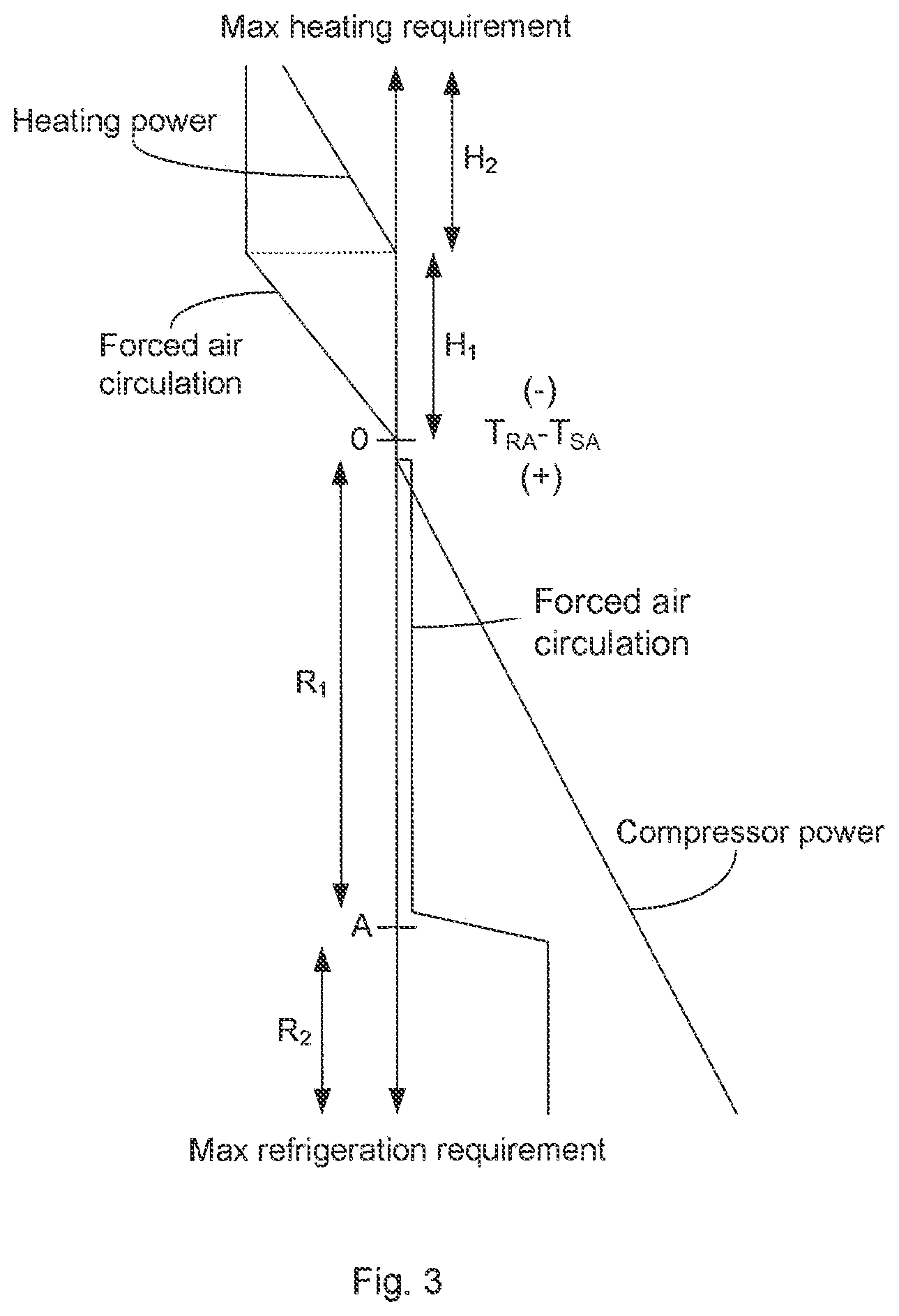
FIG. 3 is a diagram illustrating the operation of the invention in dependence on the actual requirement for heating or refrigeration.
DETAILED DESCRIPTION OF THE INVENTION
Before any embodiments of the invention are explained in detail, it is to be understood that the invention is not limited in its application to the details of construction and the arrangement of components set forth in the following description or illustrated in the following drawings. The invention is capable of other embodiments and of being practiced or of being carried out in various ways.
FIG. 1 is a simplified diagram of the basic components of a typical one-stage vapor-compression refrigeration system 100 according to the invention. In this cycle, a circulating refrigerant enters the compressor 110 as a vapor. In the compressor the vapor is compressed and exits the compressor superheated. The superheated vapor travels through the condenser 120 which first cools and removes the superheat and then condenses the vapor into a liquid by removing additional heat at constant pressure and temperature. The liquid refrigerant goes through an expansion valve 130 (also called a throttle valve) where its pressure abruptly decreases, causing flash evaporation and auto-refrigeration of, typically, less than half of the liquid. That results in a mixture of liquid and vapor at a lower temperature and pressure. The cold liquid-vapor mixture then travels through the evaporator 140 coil or tubes and is completely vaporized by cooling the warm return air RA returning from the refrigerated space being blown by an evaporator fan 150 across the evaporator coil or tubes. The cool supply air SA is blown into the refrigerated space. The resulting refrigerant vapor returns to the compressor inlet to complete the thermodynamic cycle. A condenser fan 160 removes condensation heat from the condenser 120. A controller 170 controls the operation of the refrigeration system and its individual components.
During operation water vapor will condensate on the evaporator 140 and form a layer of ice which will degrade the efficiency of the evaporator. The ice is removed in defrosting cycles where the compressor 110 and the evaporator fan 150 are inactivated, and a heater 180 is activated which will heat the evaporator 140. A temperature sensor 190 senses the temperature of the evaporator 140 and when it has been determined, based on the sensed evaporator temperature, that the ice is melted, the compressor 110 is again activated. When the temperature of the evaporator is sufficiently low the evaporator fan 150 is activated and the refrigeration system is in operation again.
The refrigeration system 100 can have one or more evaporator fans 150. The power of the evaporator fan motors can be controlled in two or more steps or continuously by the controller 170. For simplicity, only high speed operation and low speed operation are described, but the person having ordinary skill in the art will understand that the described method applies in general to motors with controllable speed.
FIG. 2 shows schematically a portion of a refrigerated container 200 loaded with cargo 210 to be refrigerated. The container 200 has a refrigeration system 100 installed in one end, and the container has doors (not shown) in the opposite end for loading and unloading the cargo 210. The evaporator fan or fans 150 of the refrigeration system 100 blow refrigerated supply air SA into the container where it circulates around the cargo 210 and returns as return air RA to the refrigeration system 100.
The energy required for circulating the air in the container is ultimately dissipated as heat in the container due to friction. Depending on whether the evaporator fan 150 is operated in a low speed mode or in a high speed mode it delivers from a few hundred watts up to a few kilowatts (kW) which is dissipated as heat in the container. This energy adds to the energy that enters the container from the ambient and the heat that is generated by the cargo itself, all of which must be removed by the refrigeration system. Assuming efficiencies of 100% of both the evaporator fan and the refrigeration system, for each kW consumed by the evaporator fan another kW will be consumed by the refrigeration system.
FIG. 3 illustrates the operation of the invention in dependence on the actual requirement for heating or refrigeration. Based on observed temperature T.sub.RA of the return air RA and the temperature T.sub.SA of the supply air SA and the difference T.sub.RA-T.sub.SA of the two temperatures the requirement for heating or refrigeration is calculated.
When the observed temperature difference T.sub.RA-T.sub.SA indicates that neither heating nor refrigeration is required, then none of the compressor, the evaporator fan and the heater is operated, since there is nothing to correct. However, at predetermined intervals the evaporator fan is activated to circulate air in the container and to draw the return air stream past the return air temperature sensor to measure its temperature to determine whether heating or refrigeration is needed.
When a requirement for moderate heating is determined as in interval H.sub.1, the evaporator fan is activated to circulate air in the container at a rate where the friction heat generated by the air flow satisfies the need for heating. This is possible with fan motors with continuously variable speed, and with other motors it can be obtained by pulse width modulation (PWM) of the electric power supplied to the motors. The speed of other (traditional) fan motors can be controlled by turning them on and off at relatively longer intervals resulting in the correct mean value of the motor speed.
At higher requirements for heating than satisfied by the evaporator fan alone, as in interval H.sub.2, the evaporator fan is operated at its full capacity and supplemented by the heater 180. The heater power is adjusted so that the friction heat from the air flow plus the heat generated by the heater satisfy the need for heating. The electric power supplied to the heater can be varied e.g. by pulse width modulating the power.
When a requirement for moderate refrigeration is determined as in interval RI, the compressor 110 is activated and the evaporator fan is activated to circulate the air in the container and pass it through the evaporator coil to be refrigerated. The circulation of air results in friction heat dissipated in the container which adds to the energy to be removed by refrigeration. The evaporator fan motor is therefore operated at a low speed which is sufficient to circulate the air so as to meet the requirement for refrigeration and to dissipate as little friction heat as possible. Variations in the refrigeration requirement are accommodated for by regulating the compressor power.
Letter A in FIG. 3 indicates a requirement for refrigeration determined by the set-point temperature T.sub.SP, by the ambient conditions outside of the container, which leaks heat energy into the container, and by the heat energy generated by the cargo, all of which are known or can be determined by measurements or observations or possibly estimated. At requirements for refrigeration higher than the requirement value A it is necessary to circulate the air in the container at a high rate and correspondingly operate the evaporation fan at a high speed. Variations in the refrigeration requirement are accommodated for by regulating the compressor power.
The change in fan speed at requirement A affects the air flow through the evaporator, and therefore the compressor power is adjusted accordingly.
The interval around the requirement value A is relatively narrow and the speed of the evaporator fan motor may be varied continuously over this interval.
Various features and advantages of the invention are set forth in the following claims.
* * * * *
D00000
D00001
D00002
XML
uspto.report is an independent third-party trademark research tool that is not affiliated, endorsed, or sponsored by the United States Patent and Trademark Office (USPTO) or any other governmental organization. The information provided by uspto.report is based on publicly available data at the time of writing and is intended for informational purposes only.
While we strive to provide accurate and up-to-date information, we do not guarantee the accuracy, completeness, reliability, or suitability of the information displayed on this site. The use of this site is at your own risk. Any reliance you place on such information is therefore strictly at your own risk.
All official trademark data, including owner information, should be verified by visiting the official USPTO website at www.uspto.gov. This site is not intended to replace professional legal advice and should not be used as a substitute for consulting with a legal professional who is knowledgeable about trademark law.