M-mode ultrasound imaging of arbitrary paths
Brewer , et al.
U.S. patent number 10,617,384 [Application Number 15/005,866] was granted by the patent office on 2020-04-14 for m-mode ultrasound imaging of arbitrary paths. This patent grant is currently assigned to MAUI IMAGING, INC.. The grantee listed for this patent is MAUI IMAGING, INC.. Invention is credited to Kenneth D. Brewer, Rozalin M. Lorenzato, Bruce R. Ritzi, David M. Smith.


| United States Patent | 10,617,384 |
| Brewer , et al. | April 14, 2020 |
M-mode ultrasound imaging of arbitrary paths
Abstract
Systems and methods of M-mode ultrasound imaging allows for M-mode imaging along user-defined paths. In various embodiments, the user-defined path can be a non-linear path or a curved path. In some embodiments, a system for M-mode ultrasound imaging can comprise a multi-aperture probe with at least a first transmitting aperture and a second receiving aperture. The receiving aperture can be separate from the transmitting aperture. In some embodiments, the transmitting aperture can be configured to transmit an unfocused, spherical, ultrasound ping signal into a region of interest. The user-defined path can define a structure of interest within the region of interest.
| Inventors: | Brewer; Kenneth D. (Santa Clara, CA), Smith; David M. (Lodi, CA), Lorenzato; Rozalin M. (Palo Alto, CA), Ritzi; Bruce R. (Sunnyvale, CA) | ||||||||||
|---|---|---|---|---|---|---|---|---|---|---|---|
| Applicant: |
|
||||||||||
| Assignee: | MAUI IMAGING, INC. (San Jose,
CA) |
||||||||||
| Family ID: | 48695413 | ||||||||||
| Appl. No.: | 15/005,866 | ||||||||||
| Filed: | January 25, 2016 |
Prior Publication Data
| Document Identifier | Publication Date | |
|---|---|---|
| US 20160135783 A1 | May 19, 2016 | |
Related U.S. Patent Documents
| Application Number | Filing Date | Patent Number | Issue Date | ||
|---|---|---|---|---|---|
| 13730346 | Dec 28, 2012 | 9265484 | |||
| 61581583 | Dec 29, 2011 | ||||
| 61691717 | Aug 21, 2012 | ||||
| Current U.S. Class: | 1/1 |
| Current CPC Class: | A61B 8/486 (20130101); A61B 8/145 (20130101); A61B 8/4444 (20130101); A61B 8/14 (20130101); A61B 8/467 (20130101); G01S 15/8927 (20130101); A61B 8/5207 (20130101); A61B 8/466 (20130101); A61B 8/463 (20130101); G01S 15/8913 (20130101); A61B 8/4477 (20130101); A61B 8/4488 (20130101) |
| Current International Class: | A61B 8/00 (20060101); G01S 15/89 (20060101); A61B 8/08 (20060101); A61B 8/14 (20060101) |
References Cited [Referenced By]
U.S. Patent Documents
| 3174286 | March 1965 | Erickson |
| 3895381 | July 1975 | Kock |
| 3974692 | August 1976 | Hassler |
| 4055988 | November 1977 | Dutton |
| 4072922 | February 1978 | Taner et al. |
| 4097835 | June 1978 | Green |
| 4105018 | August 1978 | Greenleaf et al. |
| 4180792 | December 1979 | Lederman et al. |
| 4205394 | May 1980 | Pickens |
| 4229798 | October 1980 | Rosie |
| 4259733 | March 1981 | Taner et al. |
| 4265126 | May 1981 | Papadofrangakis et al. |
| 4271842 | June 1981 | Specht et al. |
| 4325257 | April 1982 | Kino et al. |
| 4327738 | May 1982 | Green et al. |
| 4333474 | June 1982 | Nigam |
| 4339952 | July 1982 | Foster |
| 4452084 | June 1984 | Taenzer |
| 4501279 | February 1985 | Seo |
| 4511998 | April 1985 | Kanda et al. |
| 4539847 | September 1985 | Paap |
| 4566459 | January 1986 | Umemura et al. |
| 4567768 | February 1986 | Satoh et al. |
| 4604697 | August 1986 | Luthra et al. |
| 4662222 | May 1987 | Johnson |
| 4669482 | June 1987 | Ophir |
| 4682497 | July 1987 | Sasaki |
| 4694434 | September 1987 | Vonn Ramm et al. |
| 4781199 | November 1988 | Hirama et al. |
| 4817434 | April 1989 | Anderson |
| 4831601 | May 1989 | Breimesser et al. |
| 4893284 | January 1990 | Magrane |
| 4893628 | January 1990 | Angelsen |
| 4990462 | February 1991 | Sliwa, Jr. |
| 5050588 | September 1991 | Grey et al. |
| 5062295 | November 1991 | Shakkottai et al. |
| 5141738 | August 1992 | Rasor et al. |
| 5161536 | November 1992 | Vilkomerson et al. |
| 5197475 | March 1993 | Antich et al. |
| 5226019 | July 1993 | Bahorich |
| 5230339 | July 1993 | Charlebois |
| 5269309 | December 1993 | Fort et al. |
| 5278757 | January 1994 | Hoctor et al. |
| 5293871 | March 1994 | Reinstein et al. |
| 5299576 | April 1994 | Shiba |
| 5301674 | April 1994 | Erikson et al. |
| 5305756 | April 1994 | Entrekin et al. |
| 5339282 | August 1994 | Kuhn et al. |
| 5340510 | August 1994 | Bowen |
| 5345426 | September 1994 | Lipschutz |
| 5349960 | September 1994 | Gondo |
| 5355888 | October 1994 | Kendall |
| 5381794 | January 1995 | Tei et al. |
| 5398216 | March 1995 | Hall et al. |
| 5409010 | April 1995 | Beach et al. |
| 5442462 | August 1995 | Guissin |
| 5454372 | October 1995 | Banjanin et al. |
| 5503152 | April 1996 | Oakley et al. |
| 5515853 | May 1996 | Smith et al. |
| 5515856 | May 1996 | Olstad et al. |
| 5522393 | June 1996 | Phillips et al. |
| 5526815 | June 1996 | Granz et al. |
| 5544659 | August 1996 | Banjanin |
| 5558092 | September 1996 | Unger et al. |
| 5564423 | October 1996 | Mele et al. |
| 5568812 | October 1996 | Murashita et al. |
| 5570691 | November 1996 | Wright et al. |
| 5581517 | December 1996 | Gee et al. |
| 5625149 | April 1997 | Gururaja et al. |
| 5628320 | May 1997 | Teo |
| 5673697 | October 1997 | Bryan et al. |
| 5675550 | October 1997 | Ekhaus |
| 5720291 | February 1998 | Schwartz |
| 5720708 | February 1998 | Lu et al. |
| 5744898 | April 1998 | Smith et al. |
| 5769079 | June 1998 | Hossack |
| 5784334 | July 1998 | Sena et al. |
| 5785654 | July 1998 | Linuma et al. |
| 5795297 | August 1998 | Daigle |
| 5797845 | August 1998 | Barabash et al. |
| 5798459 | August 1998 | Ohba et al. |
| 5820561 | October 1998 | Olstad et al. |
| 5838564 | November 1998 | Bahorich et al. |
| 5850622 | December 1998 | Vassiliou et al. |
| 5862100 | January 1999 | VerWest |
| 5870691 | February 1999 | Partyka et al. |
| 5876342 | March 1999 | Chen et al. |
| 5891038 | April 1999 | Seyed-Bolorforosh et al. |
| 5892732 | April 1999 | Gersztenkorn |
| 5916169 | June 1999 | Hanafy et al. |
| 5919139 | July 1999 | Lin |
| 5920285 | July 1999 | Benjamin |
| 5930730 | July 1999 | Marfurt et al. |
| 5940778 | August 1999 | Marfurt et al. |
| 5951479 | September 1999 | Holm et al. |
| 5964707 | October 1999 | Fenster et al. |
| 5969661 | October 1999 | Benjamin |
| 5999836 | December 1999 | Nelson et al. |
| 6007499 | December 1999 | Martin et al. |
| 6013032 | January 2000 | Savord |
| 6014473 | January 2000 | Hossack et al. |
| 6048315 | April 2000 | Chiao et al. |
| 6049509 | April 2000 | Sonneland et al. |
| 6050943 | April 2000 | Slayton et al. |
| 6056693 | May 2000 | Haider |
| 6058074 | May 2000 | Swan et al. |
| 6077224 | June 2000 | Lang et al. |
| 6092026 | July 2000 | Bahorich et al. |
| 6122538 | September 2000 | Sliwa, Jr. et al. |
| 6123670 | September 2000 | Mo |
| 6129672 | October 2000 | Seward et al. |
| 6135960 | October 2000 | Holmberg |
| 6138075 | October 2000 | Yost |
| 6148095 | November 2000 | Prause et al. |
| 6162175 | December 2000 | Marian, Jr. et al. |
| 6166384 | December 2000 | Dentinger et al. |
| 6166853 | December 2000 | Sepia et al. |
| 6193665 | February 2001 | Hall et al. |
| 6196739 | March 2001 | Silverbrook |
| 6200266 | March 2001 | Shokrollahi et al. |
| 6210335 | April 2001 | Miller |
| 6213958 | April 2001 | Winder |
| 6221019 | April 2001 | Kantorovich |
| 6231511 | May 2001 | Bae |
| 6238342 | May 2001 | Feleppa et al. |
| 6246901 | June 2001 | Benaron |
| 6251073 | June 2001 | Imran et al. |
| 6264609 | July 2001 | Herrington et al. |
| 6266551 | July 2001 | Osadchy et al. |
| 6278949 | August 2001 | Alam |
| 6289230 | September 2001 | Chaiken et al. |
| 6299580 | October 2001 | Asafusa |
| 6304684 | October 2001 | Niczyporuk et al. |
| 6309356 | October 2001 | Ustuner et al. |
| 6324453 | November 2001 | Breed et al. |
| 6345539 | February 2002 | Rawes et al. |
| 6361500 | March 2002 | Masters |
| 6363033 | March 2002 | Cole et al. |
| 6370480 | April 2002 | Gupta et al. |
| 6374185 | April 2002 | Taner et al. |
| 6394955 | May 2002 | Periitz |
| 6423002 | July 2002 | Hossack |
| 6436046 | August 2002 | Napolitano et al. |
| 6449821 | September 2002 | Sudol et al. |
| 6450965 | September 2002 | Williams et al. |
| 6468216 | October 2002 | Powers et al. |
| 6471650 | October 2002 | Powers et al. |
| 6475150 | November 2002 | Haddad |
| 6480790 | November 2002 | Calvert et al. |
| 6487502 | November 2002 | Taner |
| 6499536 | December 2002 | Ellingsen |
| 6508768 | January 2003 | Hall et al. |
| 6508770 | January 2003 | Cai |
| 6517484 | February 2003 | Wilk et al. |
| 6526163 | February 2003 | Heimann et al. |
| 6543272 | April 2003 | Vitek |
| 6547732 | April 2003 | Jago |
| 6551246 | April 2003 | Ustuner et al. |
| 6565510 | May 2003 | Haider |
| 6585647 | July 2003 | Winder |
| 6597171 | July 2003 | Hurlimann et al. |
| 6604421 | August 2003 | Li |
| 6614560 | September 2003 | Silverbrook |
| 6620101 | September 2003 | Azzam et al. |
| 6652461 | November 2003 | Levkovitz |
| 6668654 | December 2003 | Dubois et al. |
| 6672165 | January 2004 | Rather et al. |
| 6681185 | January 2004 | Young et al. |
| 6690816 | February 2004 | Aylward et al. |
| 6692450 | February 2004 | Coleman |
| 6695778 | February 2004 | Golland et al. |
| 6702745 | March 2004 | Smythe |
| 6704692 | March 2004 | Banerjee et al. |
| 6719693 | April 2004 | Richard |
| 6728567 | April 2004 | Rather et al. |
| 6752762 | June 2004 | DeJong et al. |
| 6755787 | June 2004 | Hossack et al. |
| 6780152 | August 2004 | Ustuner et al. |
| 6790182 | September 2004 | Eck et al. |
| 6835178 | December 2004 | Wilson et al. |
| 6837853 | January 2005 | Marian |
| 6843770 | January 2005 | Sumanaweera |
| 6847737 | January 2005 | Kouri et al. |
| 6854332 | February 2005 | Alleyne |
| 6865140 | March 2005 | Thomenius et al. |
| 6932767 | August 2005 | Landry et al. |
| 7033320 | April 2006 | Von Behren et al. |
| 7087023 | August 2006 | Daft et al. |
| 7104956 | September 2006 | Christopher |
| 7217243 | May 2007 | Takeuchi |
| 7221867 | May 2007 | Silverbrook |
| 7231072 | June 2007 | Yamano et al. |
| 7269299 | September 2007 | Schroeder |
| 7283652 | October 2007 | Mendonca et al. |
| 7285094 | October 2007 | Nohara et al. |
| 7293462 | November 2007 | Lee et al. |
| 7313053 | December 2007 | Wodnicki |
| 7366704 | April 2008 | Reading et al. |
| 7402136 | July 2008 | Hossack et al. |
| 7410469 | August 2008 | Talish et al. |
| 7415880 | August 2008 | Renzel |
| 7443765 | October 2008 | Thomenius et al. |
| 7444875 | November 2008 | Wu et al. |
| 7447535 | November 2008 | Lavi |
| 7448998 | November 2008 | Robinson |
| 7466848 | December 2008 | Metaxas et al. |
| 7469096 | December 2008 | Silverbrook |
| 7474778 | January 2009 | Shinomura et al. |
| 7481577 | January 2009 | Ramamurthy et al. |
| 7491171 | February 2009 | Barthe et al. |
| 7497828 | March 2009 | Wilk et al. |
| 7497830 | March 2009 | Li |
| 7510529 | March 2009 | Chou et al. |
| 7514851 | April 2009 | Wilser et al. |
| 7549962 | June 2009 | Dreschel et al. |
| 7574026 | August 2009 | Rasche et al. |
| 7625343 | December 2009 | Cao et al. |
| 7637869 | December 2009 | Sudol |
| 7668583 | February 2010 | Fegert et al. |
| 7674228 | March 2010 | Williams et al. |
| 7682311 | March 2010 | Simopoulos et al. |
| 7699776 | April 2010 | Walker et al. |
| 7722541 | May 2010 | Cai |
| 7744532 | June 2010 | Ustuner et al. |
| 7750311 | July 2010 | Daghighian |
| 7764984 | July 2010 | Desmedt et al. |
| 7785260 | August 2010 | Umemura et al. |
| 7787680 | August 2010 | Ahn et al. |
| 7806828 | October 2010 | Stringer |
| 7819810 | October 2010 | Stringer et al. |
| 7822250 | October 2010 | Yao et al. |
| 7824337 | November 2010 | Abe et al. |
| 7833163 | November 2010 | Cal |
| 7837624 | November 2010 | Hossack et al. |
| 7846097 | December 2010 | Jones et al. |
| 7850613 | December 2010 | Stribling |
| 7862508 | January 2011 | Davies et al. |
| 7876945 | January 2011 | Lotjonen |
| 7880154 | February 2011 | Otto |
| 7887486 | February 2011 | Ustuner et al. |
| 7901358 | March 2011 | Mehi et al. |
| 7907758 | March 2011 | Hill et al. |
| 7914451 | March 2011 | Davies |
| 7919906 | April 2011 | Cerofolini |
| 7926350 | April 2011 | Kroning et al. |
| 7927280 | April 2011 | Davidsen |
| 7972271 | July 2011 | Johnson et al. |
| 7984637 | July 2011 | Ao et al. |
| 7984651 | July 2011 | Randall et al. |
| 8002705 | August 2011 | Napolitano et al. |
| 8007439 | August 2011 | Specht |
| 8057392 | November 2011 | Hossack et al. |
| 8057393 | November 2011 | Yao et al. |
| 8079263 | December 2011 | Randall et al. |
| 8079956 | December 2011 | Azuma et al. |
| 8088067 | January 2012 | Vortman et al. |
| 8088068 | January 2012 | Yao et al. |
| 8088071 | January 2012 | Hwang et al. |
| 8105239 | January 2012 | Specht |
| 8135190 | March 2012 | Bae et al. |
| 8157737 | April 2012 | Zhang et al. |
| 8182427 | May 2012 | Wu et al. |
| 8202219 | June 2012 | Luo et al. |
| 8265175 | September 2012 | Barsoum et al. |
| 8277383 | October 2012 | Specht |
| 8279705 | October 2012 | Choi et al. |
| 8412307 | April 2013 | Willis et al. |
| 8414564 | April 2013 | Goldshleger et al. |
| 8419642 | April 2013 | Sandrin et al. |
| 8473239 | June 2013 | Specht et al. |
| 8478382 | July 2013 | Burnside et al. |
| 8483804 | July 2013 | Hsieh et al. |
| 8532951 | September 2013 | Roy et al. |
| 8582848 | November 2013 | Funka-Lea et al. |
| 8602993 | December 2013 | Specht et al. |
| 8627724 | January 2014 | Papadopoulos et al. |
| 8634615 | January 2014 | Brabec |
| 8672846 | March 2014 | Napolitano et al. |
| 8684936 | April 2014 | Specht |
| 9036887 | May 2015 | Fouras et al. |
| 9072495 | July 2015 | Specht |
| 9146313 | September 2015 | Specht et al. |
| 9176078 | November 2015 | Flohr et al. |
| 9192355 | November 2015 | Specht et al. |
| 9220478 | December 2015 | Smith et al. |
| 9247926 | February 2016 | Smith et al. |
| 9265484 | February 2016 | Brewer |
| 9268777 | February 2016 | Lu et al. |
| 9271661 | March 2016 | Moghari et al. |
| 9277861 | March 2016 | Kowal et al. |
| 9282945 | March 2016 | Specht et al. |
| 9392986 | July 2016 | Ning et al. |
| 9576354 | February 2017 | Fouras et al. |
| 9606206 | March 2017 | Boernert et al. |
| 10342518 | July 2019 | Specht et al. |
| 10380399 | August 2019 | Call et al. |
| 2002/0035864 | March 2002 | Paltieli et al. |
| 2002/0087071 | July 2002 | Schmitz et al. |
| 2002/0111568 | August 2002 | Bukshpan |
| 2002/0138003 | September 2002 | Bukshpan |
| 2002/0161299 | October 2002 | Prater et al. |
| 2003/0013962 | January 2003 | Bjaerum et al. |
| 2003/0028111 | February 2003 | Vaezy et al. |
| 2003/0040669 | February 2003 | Grass et al. |
| 2003/0228053 | December 2003 | Li et al. |
| 2004/0015079 | January 2004 | Berger et al. |
| 2004/0054283 | March 2004 | Corey et al. |
| 2004/0068184 | April 2004 | Trahey et al. |
| 2004/0100163 | May 2004 | Baumgartner et al. |
| 2004/0111028 | June 2004 | Abe |
| 2004/0122313 | June 2004 | Moore et al. |
| 2004/0122322 | June 2004 | Moore et al. |
| 2004/0127793 | July 2004 | Mendlein et al. |
| 2004/0138565 | July 2004 | Trucco |
| 2004/0144176 | July 2004 | Yoden |
| 2004/0215075 | October 2004 | Zagzebski et al. |
| 2004/0236217 | November 2004 | Cerwin et al. |
| 2004/0236223 | November 2004 | Barnes et al. |
| 2004/0267132 | December 2004 | Podany |
| 2005/0004449 | January 2005 | Mitschke et al. |
| 2005/0053305 | March 2005 | Li et al. |
| 2005/0054910 | March 2005 | Tremblay et al. |
| 2005/0061536 | March 2005 | Proulx |
| 2005/0090743 | April 2005 | Kawashima et al. |
| 2005/0090745 | April 2005 | Steen |
| 2005/0111846 | May 2005 | Steinbacher et al. |
| 2005/0113689 | May 2005 | Gritzky |
| 2005/0113694 | May 2005 | Haugen et al. |
| 2005/0124883 | June 2005 | Hunt |
| 2005/0131300 | June 2005 | Bakircioglu et al. |
| 2005/0147297 | July 2005 | McLaughlin et al. |
| 2005/0165312 | July 2005 | Knowles et al. |
| 2005/0203404 | September 2005 | Freiburger |
| 2005/0215883 | September 2005 | Hundley et al. |
| 2005/0240125 | October 2005 | Makin et al. |
| 2005/0252295 | November 2005 | Fink et al. |
| 2005/0281447 | December 2005 | Moreau-Gobard et al. |
| 2005/0288588 | December 2005 | Weber et al. |
| 2006/0058664 | March 2006 | Barthe et al. |
| 2006/0062447 | March 2006 | Rinck et al. |
| 2006/0074313 | April 2006 | Slayton et al. |
| 2006/0074315 | April 2006 | Liang et al. |
| 2006/0074320 | April 2006 | Yoo et al. |
| 2006/0079759 | April 2006 | Vaillant et al. |
| 2006/0079778 | April 2006 | Mo et al. |
| 2006/0079782 | April 2006 | Beach et al. |
| 2006/0094962 | May 2006 | Clark |
| 2006/0111634 | May 2006 | Wu |
| 2006/0122506 | June 2006 | Davies et al. |
| 2006/0173327 | August 2006 | Kim |
| 2006/0262961 | November 2006 | Noising et al. |
| 2006/0270934 | November 2006 | Savord et al. |
| 2007/0016022 | January 2007 | Blalock et al. |
| 2007/0016044 | January 2007 | Blalock et al. |
| 2007/0036414 | February 2007 | Georgescu et al. |
| 2007/0055155 | March 2007 | Owen et al. |
| 2007/0073781 | March 2007 | Adkins et al. |
| 2007/0078345 | April 2007 | Mo et al. |
| 2007/0088213 | April 2007 | Poland |
| 2007/0138157 | June 2007 | Dane et al. |
| 2007/0161898 | July 2007 | Hao et al. |
| 2007/0161904 | July 2007 | Urbano |
| 2007/0167752 | July 2007 | Proulx et al. |
| 2007/0167824 | July 2007 | Lee et al. |
| 2007/0232914 | October 2007 | Chen et al. |
| 2007/0238985 | October 2007 | Smith et al. |
| 2007/0242567 | October 2007 | Daft et al. |
| 2008/0110261 | May 2008 | Randall et al. |
| 2008/0110263 | May 2008 | Klessel et al. |
| 2008/0112265 | May 2008 | Urbano et al. |
| 2008/0114241 | May 2008 | Randall et al. |
| 2008/0114245 | May 2008 | Randall et al. |
| 2008/0114246 | May 2008 | Randall et al. |
| 2008/0114247 | May 2008 | Urbano et al. |
| 2008/0114248 | May 2008 | Urbano et al. |
| 2008/0114249 | May 2008 | Randall et al. |
| 2008/0114250 | May 2008 | Urbano et al. |
| 2008/0114251 | May 2008 | Weymer et al. |
| 2008/0114252 | May 2008 | Randall et al. |
| 2008/0114253 | May 2008 | Randall et al. |
| 2008/0114255 | May 2008 | Schwartz et al. |
| 2008/0125659 | May 2008 | Wilser et al. |
| 2008/0181479 | July 2008 | Yang et al. |
| 2008/0183075 | July 2008 | Govari et al. |
| 2008/0188747 | August 2008 | Randall et al. |
| 2008/0188750 | August 2008 | Randall et al. |
| 2008/0194957 | August 2008 | Hoctor et al. |
| 2008/0194958 | August 2008 | Lee et al. |
| 2008/0194959 | August 2008 | Wang et al. |
| 2008/0208061 | August 2008 | Halmann |
| 2008/0242996 | October 2008 | Hall et al. |
| 2008/0249408 | October 2008 | Palmeri et al. |
| 2008/0255452 | October 2008 | Entrekin |
| 2008/0269604 | October 2008 | Boctor et al. |
| 2008/0269613 | October 2008 | Summers et al. |
| 2008/0275344 | November 2008 | Glide-Hurst et al. |
| 2008/0285819 | November 2008 | Konofagou et al. |
| 2008/0287787 | November 2008 | Sauer et al. |
| 2008/0294045 | November 2008 | Ellington et al. |
| 2008/0294050 | November 2008 | Shinomura et al. |
| 2008/0294052 | November 2008 | Wilser et al. |
| 2008/0306382 | December 2008 | Guracar et al. |
| 2008/0306386 | December 2008 | Baba et al. |
| 2008/0319317 | December 2008 | Kamiyama et al. |
| 2009/0010459 | January 2009 | Garbini et al. |
| 2009/0012393 | January 2009 | Choi |
| 2009/0015665 | January 2009 | Willsie |
| 2009/0016163 | January 2009 | Freeman et al. |
| 2009/0018445 | January 2009 | Schers et al. |
| 2009/0024039 | January 2009 | Wang et al. |
| 2009/0036780 | February 2009 | Abraham |
| 2009/0043206 | February 2009 | Towfiq et al. |
| 2009/0048519 | February 2009 | Hossack et al. |
| 2009/0069681 | March 2009 | Lundberg et al. |
| 2009/0069686 | March 2009 | Daft et al. |
| 2009/0069692 | March 2009 | Cooley et al. |
| 2009/0079299 | March 2009 | Bradley et al. |
| 2009/0099483 | April 2009 | Rybyanets |
| 2009/0112095 | April 2009 | Daigle |
| 2009/0131797 | May 2009 | Jeong et al. |
| 2009/0143680 | June 2009 | Yao et al. |
| 2009/0148012 | June 2009 | Altmann et al. |
| 2009/0150094 | June 2009 | Van Velsor et al. |
| 2009/0182233 | July 2009 | Wodnicki |
| 2009/0182237 | July 2009 | Angelsen et al. |
| 2009/0198134 | August 2009 | Hashimoto et al. |
| 2009/0203997 | August 2009 | Ustuner |
| 2009/0208080 | August 2009 | Grau et al. |
| 2009/0259128 | October 2009 | Stribling |
| 2009/0264760 | October 2009 | Lazebnik et al. |
| 2009/0306510 | December 2009 | Hashiba et al. |
| 2009/0326379 | December 2009 | Daigle et al. |
| 2010/0010354 | January 2010 | Skerl et al. |
| 2010/0016725 | January 2010 | Thiele |
| 2010/0036258 | February 2010 | Dietz et al. |
| 2010/0063397 | March 2010 | Wagner |
| 2010/0063399 | March 2010 | Walker et al. |
| 2010/0069751 | March 2010 | Hazard et al. |
| 2010/0069756 | March 2010 | Ogasawara et al. |
| 2010/0085383 | April 2010 | Cohen et al. |
| 2010/0106431 | April 2010 | Baba et al. |
| 2010/0109481 | May 2010 | Buccafusca |
| 2010/0121193 | May 2010 | Fukukita et al. |
| 2010/0121196 | May 2010 | Hwang et al. |
| 2010/0130855 | May 2010 | Lundberg et al. |
| 2010/0145195 | June 2010 | Hyun |
| 2010/0168566 | July 2010 | Bercoff et al. |
| 2010/0168578 | July 2010 | Garson, Jr. et al. |
| 2010/0174194 | July 2010 | Chiang et al. |
| 2010/0174198 | July 2010 | Young et al. |
| 2010/0191110 | July 2010 | Insana et al. |
| 2010/0217124 | August 2010 | Cooley |
| 2010/0228126 | September 2010 | Emery et al. |
| 2010/0240994 | September 2010 | Zheng |
| 2010/0249570 | September 2010 | Carson et al. |
| 2010/0249596 | September 2010 | Magee |
| 2010/0256488 | October 2010 | Kim et al. |
| 2010/0262013 | October 2010 | Smith |
| 2010/0266176 | October 2010 | Masumoto et al. |
| 2010/0286525 | November 2010 | Osumi |
| 2010/0286527 | November 2010 | Cannon et al. |
| 2010/0310143 | December 2010 | Rao et al. |
| 2010/0317971 | December 2010 | Fan et al. |
| 2010/0324418 | December 2010 | El-Aklouk et al. |
| 2010/0324423 | December 2010 | El-Aklouk et al. |
| 2010/0329521 | December 2010 | Beymer et al. |
| 2011/0005322 | January 2011 | Ustuner |
| 2011/0016977 | January 2011 | Guracar |
| 2011/0021915 | January 2011 | Feng |
| 2011/0021920 | January 2011 | Shafir et al. |
| 2011/0021923 | January 2011 | Daft et al. |
| 2011/0033098 | February 2011 | Richter et al. |
| 2011/0044133 | February 2011 | Tokita |
| 2011/0066030 | March 2011 | Yao |
| 2011/0098565 | April 2011 | Masuzawa |
| 2011/0112400 | May 2011 | Emery et al. |
| 2011/0112404 | May 2011 | Gourevitch |
| 2011/0125017 | May 2011 | Ramamurthy et al. |
| 2011/0178441 | July 2011 | Tyler |
| 2011/0270088 | November 2011 | Shiina |
| 2011/0301470 | December 2011 | Sato et al. |
| 2011/0306886 | December 2011 | Daft et al. |
| 2011/0319764 | December 2011 | Okada et al. |
| 2012/0004545 | January 2012 | Ziv-Ari et al. |
| 2012/0035482 | February 2012 | Kim et al. |
| 2012/0036934 | February 2012 | Kroning et al. |
| 2012/0085173 | April 2012 | Papadopoulos et al. |
| 2012/0095347 | April 2012 | Adam et al. |
| 2012/0101378 | April 2012 | Lee |
| 2012/0114210 | May 2012 | Kim et al. |
| 2012/0116226 | May 2012 | Specht |
| 2012/0121150 | May 2012 | Murashita |
| 2012/0137778 | June 2012 | Kitazawa et al. |
| 2012/0140595 | June 2012 | Amemiya |
| 2012/0141002 | June 2012 | Urbano et al. |
| 2012/0165670 | June 2012 | Shi et al. |
| 2012/0179044 | July 2012 | Chiang et al. |
| 2012/0226201 | September 2012 | Clark et al. |
| 2012/0235998 | September 2012 | Smith-Casem et al. |
| 2012/0243763 | September 2012 | Wen et al. |
| 2012/0253194 | October 2012 | Tamura |
| 2012/0265075 | October 2012 | Pedrizzetti et al. |
| 2012/0277585 | November 2012 | Koenig et al. |
| 2013/0070062 | March 2013 | Fouras et al. |
| 2013/0076207 | March 2013 | Krohn et al. |
| 2013/0079639 | March 2013 | Hoctor et al. |
| 2013/0083628 | April 2013 | Qiao et al. |
| 2013/0088122 | April 2013 | Krohn et al. |
| 2013/0116561 | May 2013 | Rothberg et al. |
| 2013/0131516 | May 2013 | Katsuyama |
| 2013/0144165 | June 2013 | Ebbini et al. |
| 2013/0144166 | June 2013 | Specht et al. |
| 2013/0204136 | August 2013 | Duric et al. |
| 2013/0204137 | August 2013 | Roy et al. |
| 2013/0218012 | August 2013 | Specht et al. |
| 2013/0253325 | September 2013 | Call et al. |
| 2013/0258805 | October 2013 | Hansen et al. |
| 2013/0261463 | October 2013 | Chiang et al. |
| 2014/0043933 | February 2014 | Belevich et al. |
| 2014/0058266 | February 2014 | Call et al. |
| 2014/0073921 | March 2014 | Specht et al. |
| 2014/0086014 | March 2014 | Kobayashi |
| 2014/0147013 | May 2014 | Shandas et al. |
| 2014/0243673 | August 2014 | Anand et al. |
| 2014/0269209 | September 2014 | Smith et al. |
| 2015/0045668 | February 2015 | Smith et al. |
| 2015/0080727 | March 2015 | Specht et al. |
| 2015/0297184 | October 2015 | Specht |
| 2015/0374345 | December 2015 | Specht et al. |
| 2016/0095579 | April 2016 | Smith et al. |
| 2016/0157833 | June 2016 | Smith et al. |
| 2017/0074982 | March 2017 | Smith et al. |
| 2017/0079621 | March 2017 | Specht et al. |
| 2018/0049717 | February 2018 | Adam et al. |
| 2018/0153511 | June 2018 | Specht et al. |
| 2018/0279991 | October 2018 | Call et al. |
| 2019/0008487 | January 2019 | Belevich et al. |
| 2019/0021697 | January 2019 | Specht et al. |
| 2019/0083058 | March 2019 | Specht |
| 2019/0175152 | June 2019 | Smith et al. |
| 2019/0200961 | July 2019 | Specht et al. |
| 2019/0328367 | October 2019 | Specht et al. |
| 1535243 | Oct 2004 | CN | |||
| 1781460 | Jun 2006 | CN | |||
| 101103927 | Jan 2008 | CN | |||
| 101116622 | Feb 2008 | CN | |||
| 101190134 | Jun 2008 | CN | |||
| 101453955 | Jun 2009 | CN | |||
| 101609150 | Dec 2009 | CN | |||
| 101843501 | Sep 2010 | CN | |||
| 101912278 | Dec 2010 | CN | |||
| 102018533 | Apr 2011 | CN | |||
| 102112047 | Jun 2011 | CN | |||
| 102123668 | Jul 2011 | CN | |||
| 102599930 | Jul 2012 | CN | |||
| 102011114333 | Mar 2013 | DE | |||
| 1949856 | Jul 2008 | EP | |||
| 2058796 | May 2009 | EP | |||
| 2101191 | Sep 2009 | EP | |||
| 2182352 | May 2010 | EP | |||
| 2187813 | May 2010 | EP | |||
| 2198785 | Jun 2010 | EP | |||
| 1757955 | Nov 2010 | EP | |||
| 2325672 | May 2011 | EP | |||
| 1462819 | Jul 2011 | EP | |||
| 2356941 | Aug 2011 | EP | |||
| 1979739 | Oct 2011 | EP | |||
| 2385391 | Nov 2011 | EP | |||
| 2294400 | Feb 2012 | EP | |||
| 2453256 | May 2012 | EP | |||
| 1840594 | Jun 2012 | EP | |||
| 2514368 | Oct 2012 | EP | |||
| 1850743 | Dec 2012 | EP | |||
| 1594404 | Sep 2013 | EP | |||
| 2026280 | Oct 2013 | EP | |||
| 2851662 | Aug 2004 | FR | |||
| S49-11189 | Jan 1974 | JP | |||
| S54-44375 | Apr 1979 | JP | |||
| S55-103839 | Aug 1980 | JP | |||
| 57-31848 | Feb 1982 | JP | |||
| 58-223059 | Dec 1983 | JP | |||
| 59-101143 | Jun 1984 | JP | |||
| S59-174151 | Oct 1984 | JP | |||
| S60-13109 | Jan 1985 | JP | |||
| S60-68836 | Apr 1985 | JP | |||
| 01164354 | Jun 1989 | JP | |||
| 2-501431 | May 1990 | JP | |||
| 03015455 | Jan 1991 | JP | |||
| 03126443 | May 1991 | JP | |||
| 04017842 | Jan 1992 | JP | |||
| 4-67856 | Mar 1992 | JP | |||
| 05-042138 | Feb 1993 | JP | |||
| 6-125908 | May 1994 | JP | |||
| 06254092 | Sep 1994 | JP | |||
| 7-051266 | Feb 1995 | JP | |||
| 07204201 | Aug 1995 | JP | |||
| 08154930 | Jun 1996 | JP | |||
| 08-252253 | Oct 1996 | JP | |||
| 9-103429 | Apr 1997 | JP | |||
| 9-201361 | Aug 1997 | JP | |||
| 2777197 | May 1998 | JP | |||
| 10-216128 | Aug 1998 | JP | |||
| 11-089833 | Apr 1999 | JP | |||
| 11-239578 | Sep 1999 | JP | |||
| 2001-507794 | Jun 2001 | JP | |||
| 2001-245884 | Sep 2001 | JP | |||
| 2002-209894 | Jul 2002 | JP | |||
| 2002-253548 | Sep 2002 | JP | |||
| 2002-253549 | Sep 2002 | JP | |||
| 2003235839 | Aug 2003 | JP | |||
| 2004-167092 | Jun 2004 | JP | |||
| 2004-215987 | Aug 2004 | JP | |||
| 2004-337457 | Dec 2004 | JP | |||
| 2004-351214 | Dec 2004 | JP | |||
| 2004340809 | Dec 2004 | JP | |||
| 2005046192 | Feb 2005 | JP | |||
| 2005152187 | Jun 2005 | JP | |||
| 2005-523792 | Aug 2005 | JP | |||
| 2005-526539 | Sep 2005 | JP | |||
| 2006051356 | Feb 2006 | JP | |||
| 2006-61203 | Mar 2006 | JP | |||
| 2006-122657 | May 2006 | JP | |||
| 2006130313 | May 2006 | JP | |||
| 2006204923 | Aug 2006 | JP | |||
| 2007-325937 | Dec 2007 | JP | |||
| 2008-122209 | May 2008 | JP | |||
| 2008-513763 | May 2008 | JP | |||
| 2008515557 | May 2008 | JP | |||
| 2008132342 | Jun 2008 | JP | |||
| 2008522642 | Jul 2008 | JP | |||
| 2008-259541 | Oct 2008 | JP | |||
| 2008279274 | Nov 2008 | JP | |||
| 2008307087 | Dec 2008 | JP | |||
| 2009240667 | Oct 2009 | JP | |||
| 20105375 | Jan 2010 | JP | |||
| 2010124842 | Jun 2010 | JP | |||
| 2010526626 | Aug 2010 | JP | |||
| 2011529362 | Dec 2011 | JP | |||
| 2013121493 | Jun 2013 | JP | |||
| 2014087448 | May 2014 | JP | |||
| 100715132 | Apr 2007 | KR | |||
| 1020080044737 | May 2008 | KR | |||
| 1020090103408 | Oct 2009 | KR | |||
| WO92/18054 | Oct 1992 | WO | |||
| WO98/00719 | Jan 1998 | WO | |||
| WO01/64109 | Sep 2001 | WO | |||
| WO02/084594 | Oct 2002 | WO | |||
| WO2005/009245 | Feb 2005 | WO | |||
| WO2006/114735 | Nov 2006 | WO | |||
| WO2007/127147 | Nov 2007 | WO | |||
| WO2008/097479 | Aug 2008 | WO | |||
| WO2009/060182 | May 2009 | WO | |||
| WO2010/095094 | Aug 2010 | WO | |||
| WO2010/137453 | Dec 2010 | WO | |||
| WO2010/139519 | Dec 2010 | WO | |||
| WO2011/004661 | Jan 2011 | WO | |||
| WO2011/057252 | May 2011 | WO | |||
| WO2011/064688 | Jun 2011 | WO | |||
| WO2011/100697 | Aug 2011 | WO | |||
| WO2011/123529 | Oct 2011 | WO | |||
| WO2012/028896 | Mar 2012 | WO | |||
| WO2012/049124 | Apr 2012 | WO | |||
| WO2012/049612 | Apr 2012 | WO | |||
| WO2012/078639 | Jun 2012 | WO | |||
| WO2012/091280 | Jul 2012 | WO | |||
| WO2012/112540 | Aug 2012 | WO | |||
| WO2012/131340 | Oct 2012 | WO | |||
| WO2012/160541 | Nov 2012 | WO | |||
| WO2013/059358 | Apr 2013 | WO | |||
| WO2013/109965 | Jul 2013 | WO | |||
| WO2013/116807 | Aug 2013 | WO | |||
| WO2013/116809 | Aug 2013 | WO | |||
| WO2013/116851 | Aug 2013 | WO | |||
| WO2013/116854 | Aug 2013 | WO | |||
| WO2013/116866 | Aug 2013 | WO | |||
| WO2013/128301 | Sep 2013 | WO | |||
Other References
|
Specht; U.S. Appl. No. 15/240,884 entitled "Method and apparatus to produce ultrasonic images using multiple apertures," filed Aug. 18, 2016. cited by applicant . Arigovindan et al.; Full motion and flow field recovery from echo doppler data; IEEE Transactions on Medical Imaging; 26(1); pp. 31-45; Jan. 2007. cited by applicant . Capineri et al.; A doppler system for dynamic vector velocity maps; Ultrasound in Medicine & Biology; 28(2); pp. 237-248; Feb. 28, 2002. cited by applicant . Dunmire et al.; A brief history of vector doppler; Medical Imaging 2001; International Society for Optics and Photonics; pp. 200-214; May 30, 2001. cited by applicant . Saad et al.; Computer vision approach for ultrasound doppler angle estimation; Journal of Digital Imaging; 22(6); pp. 681-688; Dec. 1, 2009. cited by applicant . Zang et al.; A high-frequency high frame rate duplex ultrasound linear array imaging system for small animal imaging; IEEE transactions on ultrasound, ferroelectrics, and frequency control; 57(7); pp. 1548-1567; Jul. 2010. cited by applicant . Specht et al.; U.S. Appl. No. 15/155,908 entitled "Determining material stiffness using multiple aperture ultrasound," filed May 16, 2016. cited by applicant . Abeysekera et al.; Alignment and calibration of dual ultrasound transducers using a wedge phantom; Ultrasound in Medicine and Biology; 37(2); pp. 271-279; Feb. 2011. cited by applicant . Carson et al.; Measurement of photoacoustic transducer position by robotic source placement and nonlinear parameter estimation; Biomedical Optics (BIOS); International Society for Optics and Photonics (9th Conf. on Biomedical Thermoacoustics, Optoacoustics, and Acousto-optics; vol. 6856; 9 pages; Feb. 28, 2008. cited by applicant . Chen et al.; Maximum-likelihood source localization and unknown sensor location estimation for wideband signals in the near-field; IEEE Transactions on Signal Processing; 50(8); pp. 1843-1854; Aug. 2002. cited by applicant . Chen et al.; Source localization and tracking of a wideband source using a randomly distributed beamforming sensor array; International Journal of High Performance Computing Applications; 16(3); pp. 259-272; Fall 2002. cited by applicant . Cristianini et al.; An Introduction to Support Vector Machines; Cambridge University Press; pp. 93-111; Mar. 2000. cited by applicant . Du et al.; User parameter free approaches to multistatic adaptive ultrasound imaging; 5th IEEE International Symposium; pp. 1287-1290, May 2008. cited by applicant . Feigenbaum, Harvey, M.D.; Echocardiography; Lippincott Williams & Wilkins; Philadelphia; 5th Ed.; pp. 482, 484; Feb. 1994. cited by applicant . Fernandez et al.; High resolution ultrasound beamforming using synthetic and adaptive imaging techniques; Proceedings IEEE International Symposium on Biomedical Imaging; Washington, D.C.; pp. 433-436; Jul. 7-10, 2002. cited by applicant . Gazor et al.; Wideband multi-source beamforming with array location calibration and direction finding; Conference on Acoustics, Speech and Signal Processing ICASSP-95; Detroit, MI; vol. 3 IEEE; pp. 1904-1907; May 9-12, 1995. cited by applicant . Haykin, Simon; Neural Networks: A Comprehensive Foundation (2nd Ed.); Prentice Hall; pp. 156-187; Jul. 16, 1998. cited by applicant . Heikkila et al.; A four-step camera calibration procedure with implicit image correction; Proceedings IEEE Computer Scociety Conference on Computer Vision and Pattern Recognition; San Juan; pp. 1106-1112; Jun. 17-19, 1997. cited by applicant . Hendee et al.; Medical Imaging Physics; Wiley-Liss, Inc. 4th Edition; Chap. 19-22; pp. 303-353; (year of pub. sufficiently earlier than effective US filing date and any foreign priority date) .COPYRGT. 2002. cited by applicant . Hsu et al.; Real-time freehand 3D ultrasound calibration; CUED/F-INFENG/TR 565; Department of Engineering, University of Cambridge, United Kingdom; 14 pages; Sep. 2006. cited by applicant . Jeffs; Beamforming: a brief introduction; Brigham Young University; 14 pages; retrieved from the internet (http://ens.ewi.tudelft.nl/Education/courses/et4235/Beamforming.pdf); Oct. 2004. cited by applicant . Khamene et al.; A novel phantom-less spatial and temporal ultrasound calibration method; Medical Image Computing and Computer-Assisted Intervention--MICCAI (Proceedings 8th Int. Conf.); Springer Berlin Heidelberg; Palm Springs, CA; pp. 65-72; Oct. 26-29, 2005. cited by applicant . Kramb et al,.; Considerations for using phased array ultrasonics in a fully automated inspection system. Review of Quantitative Nondestructive Evaluation, vol. 23, ed. D. O. Thompson and D. E. Chimenti, pp. 817-825, (year of publication is sufficiently earlier than the effective U.S. filing date and any foreign priority date) 2004. cited by applicant . Ledesma-Carbayo et al.; Spatio-temporal nonrigid registration for ultrasound cardiac motion estimation; IEEE Trans. on Medical Imaging; vol. 24; No. 9; Sep. 2005. cited by applicant . Leotta et al.; Quantitative three-dimensional echocardiography by rapid imaging . . . ; J American Society of Echocardiography; vol. 10; No. 8; pp. 830-839; Oct. 1997. cited by applicant . Li et al.; An efficient speckle tracking algorithm for ultrasonic imaging; 24; pp. 215-228; Oct. 1, 2002. cited by applicant . Morrison et al.; A probabilistic neural network based image segmentation network for magnetic resonance images; Proc. Conf. Neural Networks; Baltimore, MD; vol. 3; pp. 60-65; Jun. 1992. cited by applicant . Nadkarni et al.; Cardiac motion synchronization for 3D cardiac ultrasound imaging; Ph.D. Dissertation, University of Western Ontario; Jun. 2002. cited by applicant . Opretzka et al.; A high-frequency ultrasound imaging system combining limited-angle spatial compounding and model-based synthetic aperture focusing; IEEE Transactions on Ultrasonics, Ferroelectrics and Frequency Control, IEEE, US; 58(7); pp. 1355-1365; Jul. 2, 2011. cited by applicant . Press et al.; Cubic spline interpolation; .sctn.3.3 in "Numerical Recipes in FORTRAN: The Art of Scientific Computing", 2nd Ed.; Cambridge, England; Cambridge University Press; pp. 107-110; Sep. 1992. cited by applicant . Sakas et al.; Preprocessing and volume rendering of 3D ultrasonic data; IEEE Computer Graphics and Applications; pp. 47-54, Jul. 1995. cited by applicant . Sapia et al.; Deconvolution of ultrasonic waveforms using an adaptive wiener filter; Review of Progress in Quantitative Nondestructive Evaluation; vol. 13A; Plenum Press; pp. 855-862; (year of publication is sufficiently earlier than the effective U.S. filing date and any foreign priority date) 1994. cited by applicant . Sapia et al.; Ultrasound image deconvolution using adaptive inverse filtering; 12 IEEE Symposium on Computer-Based Medical Systems, CBMS, pp. 248-253; Jun. 1999. cited by applicant . Sapia, Mark Angelo; Multi-dimensional deconvolution of optical microscope and ultrasound imaging using adaptive least-mean-square (LMS) inverse filtering; Ph.D. Dissertation; University of Connecticut; Jan. 2000. cited by applicant . Slavine et al.; Construction, calibration and evaluation of a tissue phantom with reproducible optical properties for investigations in light emission tomography; Engineering in Medicine and Biology Workshop; Dallas, TX; IEEE pp. 122-125; Nov. 11-12, 2007. cited by applicant . Smith et al.; High-speed ultrasound volumetric imaging system. 1. Transducer design and beam steering; IEEE Trans. Ultrason., Ferroelect., Freq. Contr.; vol. 38; pp. 100-108; Mar. 1991. cited by applicant . Specht et al.; Deconvolution techniques for digital longitudinal tomography; SPIE; vol. 454; presented at Application of Optical Instrumentation in Medicine XII; pp. 319-325; Jun. 1984. cited by applicant . Specht et al.; Experience with adaptive PNN and adaptive GRNN; Proc. IEEE International Joint Conf. on Neural Networks; vol. 2; pp. 1203-1208; Orlando, FL; Jun. 1994. cited by applicant . Specht, D.F.; A general regression neural network; IEEE Trans. on Neural Networks; vol. 2.; No. 6; Nov. 1991. cited by applicant . Specht, D.F.; Blind deconvolution of motion blur using LMS inverse filtering; Lockheed Independent Research (unpublished); Jun. 23, 1975. cited by applicant . Specht, D.F.; Enhancements to probabilistic neural networks; Proc. IEEE International Joint Conf. on Neural Networks; Baltimore, MD; Jun. 1992. cited by applicant . Specht, D.F.; GRNN with double clustering; Proc. IEEE International Joint Conf. Neural Networks; Vancouver, Canada; Jul. 16-21, 2006. cited by applicant . Specht, D.F.; Probabilistic neural networks; Pergamon Press; Neural Networks; vol. 3; pp. 109-118; Feb. 1990. cited by applicant . UCLA Academic Technology; SPSS learning module: How can I analyze a subset of my data; 6 pages; retrieved from the internet (http://www.ats.ucla.edu/stat/spss/modules/subset_analyze.htm) Nov. 26, 2001. cited by applicant . Urban et al; Implementation of vibro-acoustography on a clinical ultrasound system; IEEE Transactions on Ultrasonics, Ferroelectrics, and Frequency Control; 58(6); pp. 1169-1181 (Author Manuscript, 25 pgs.); Jun. 2011. cited by applicant . Urban et al; Implementation of vibro-acoustography on a clinical ultrasound system; IEEE Ultrasonics Symposium (IUS); pp. 326-329; Oct. 14, 2010. cited by applicant . Von Ramm et al.; High-speed ultrasound volumetric imaging-System. 2. Parallel processing and image display; IEEE Trans. Ultrason., Ferroelect., Freq. Contr.; vol. 38; pp. 109-115; Mar. 1991. cited by applicant . Wang et al.; Photoacoustic tomography of biological tissues with high cross-section resolution: reconstruction and experiment; Medical Physics; 29(12); pp. 2799-2805; Dec. 2002. cited by applicant . Wells, P.N.T.; Biomedical ultrasonics; Academic Press; London, New York, San Francisco; pp. 124-125; Mar. 1977. cited by applicant . Widrow et al.; Adaptive signal processing; Prentice-Hall; Englewood Cliffs, NJ; pp. 99-116; Mar. 1985. cited by applicant . Wikipedia; Point cloud; 2 pages; retrieved Nov. 24, 2014 from the internet (https://en.wikipedia.org/w/index.php?title=Point_cloud&oldid=472583138). cited by applicant . Wikipedia; Curve fitting; 5 pages; retrieved from the internet (http:en.wikipedia.org/wiki/Curve_fitting) Dec. 19, 2010. cited by applicant . Wikipedia; Speed of sound; 17 pages; retrieved from the internet (http:en.wikipedia.org/wiki/Speed_of_sound) Feb. 15, 2011. cited by applicant . Yang et al.; Time-of-arrival calibration for improving the microwave breast cancer imaging; 2011 IEEE Topical Conf. on Biomedical Wireless Technologies, Networks, and sensing Systems (BioWireleSS); Phoenix, AZ; pp. 67-70; Jan. 16-19, 2011. cited by applicant . Belevich et al.; U.S. Appl. No. 15/400,826 entitled "Calibration of multiple aperture ultrasound probes," filed Jan. 6, 2017. cited by applicant . Davies et al.; U.S. Appl. No. 15/418,534 entitled "Ultrasound imaging with sparse array probes," filed Jan. 27, 2017. cited by applicant . Call et al.; U.S. Appl. No. 15/500,933 entitled " Network-based ultrasound imaging system," filed Feb. 1, 2017. cited by applicant . Call et al.; U.S. Appl. No. 15/495,591 entitled "Systems and methods for improving ultrasound image quality by applying weighting factors," filed Apr. 24, 2017. cited by applicant. |
Primary Examiner: Cwern; Jonathan
Attorney, Agent or Firm: Shay Glenn LLP
Parent Case Text
CROSS REFERENCE TO RELATED APPLICATIONS
This application is a continuation of U.S. application Ser. No. 13/730,346, filed Dec. 28, 2012, which application claims the benefit of US Provisional Application No. 61/581,583, titled "M-Mode Ultrasound Imaging Of Arbitrary Paths," filed Dec. 29, 2011, and U.S. Provisional Application No. 61/691,717, titled "Ultrasound Imaging System Memory Architecture," filed Aug. 21, 2012, all of which are incorporated herein by reference.
Claims
What is claimed is:
1. A method of defining and displaying an m-mode path for display in an ultrasound imaging system, the method comprising: transmitting a first unfocused ultrasound signal from a single transmitting transducer element into a region of interest including a structure of interest; receiving first echoes of the first unfocused ultrasound signal with a first group of receiving transducer elements; receiving second echoes of the first unfocused ultrasound signal with a second group of receiving transducer elements; retrieving position data describing an acoustic position of the single transmitting transducer element, each element of the first group of receiving transducer elements, and each element of the second group of receiving transducer elements; forming three-dimensional volumetric data from the first received echoes, the second received echoes, and the position data; displaying a volumetric image representing the three-dimensional volumetric data; selecting a first plane through the three-dimensional volumetric data and intersecting the structure of interest, and simultaneously displaying the selected first plane; defining an arbitrary M-mode path through the structure of interest within the selected first plane; and simultaneously displaying a graph of a magnitude of pixels along the selected M-mode path over time.
2. The method of claim 1, wherein the arbitrary M-mode path is non-linear.
3. The method of claim 2, wherein the arbitrary M-mode path has at least one curved segment.
4. The method of claim 2, wherein the arbitrary M-mode path has at least two linear segments that intersect at an angle other than 180 degrees.
5. The method of claim 1, wherein the arbitrary M-mode path has at least one linear segment and at least one curved segment.
6. The method of claim 1, wherein the arbitrary M-mode path has at least two dis-continuous segments.
7. The method of claim 1, further comprising rotating the three-dimensional volumetric image prior to selecting the first plane.
8. The method of claim 1, further comprising selecting a second plane through the three dimensional volume and displaying the selected second plane.
9. The method of claim 1, wherein defining a path through the structure of interest is performed substantially concurrently with transmitting first unfocused ultrasound signal, receiving first echoes, and receiving second echoes.
Description
INCORPORATION BY REFERENCE
All publications and patent applications mentioned in this specification are herein incorporated by reference to the same extent as if each individual publication or patent application was specifically and individually indicated to be incorporated by reference.
FIELD
This invention generally relates to ultrasound imaging, and more particularly to M-mode imaging of arbitrary paths.
BACKGROUND
Conventional ultrasound (or "scanline based" ultrasound as used herein) utilizes a phased array controller to produce and steer a substantially linear transmit waveform. In order to produce a B-mode image, a sequence of such linear waveforms (or "scanlines") may be produced and steered so as to scan across a region of interest. Echoes are received along each respective scanline. The individual scanlines from a complete scan may then be combined to form a complete image (sometimes referred to as a "sector scan" image).
A display method known as M-mode (or motion mode) imaging is commonly used in cardiology and other fields where it is desirable to view the motion of imaged objects. In some forms of M-mode imaging, echoes from a one-dimensional line are displayed over time relative to a static reference point in order to allow a clinician to evaluate movement of a particular structure (such as a cardiac wall or valve) over time. Because a traditional scanline-based ultrasound path is directional (along the scanline axis), available M-mode lines tend to be limited to paths along a scanline.
Generally, M-mode imaging provides a graphic indication of positions and movements of structures within a body over time. In some cases, a single stationary focused acoustic beam is fired at a high frame rate and the resulting M-mode images or lines are displayed side-by-side, providing an indication of the function of a heart over multiple heart cycles.
SUMMARY OF THE DISCLOSURE
A method of defining and displaying an m-mode path for display in an ultrasound imaging system, the method comprising transmitting an ultrasound signal from a transmitting transducer element into a region of interest including a structure of interest, receiving echoes with at least one receiving transducer element, producing an image of the region of interest from the received echoes, displaying the image of the region of interest including the structure of interest to a user, defining a one-pixel-wide path through the structure of interest, where the path does not lie along a line that intersects the transmitting transducer element or the receiving transducer element, and displaying a graph of a magnitude of pixels along the path over time.
In some embodiments, the path is non-linear. In other embodiments, the path has at least one curved segment. In one embodiment, the path has at least one linear segment and at least one curved segment. In another embodiment, the path has at least two linear segments that intersect at an angle other than 180 degrees. In some embodiments, the path has at least two dis-continuous segments.
In one embodiment, the transmitting transducer element lies on a separate physical transducer array from an array containing the at least one receiving transducer element.
In another embodiment, the transmitting transducer is configured to transmit an unfocused ping ultrasound signal into the region of interest.
In some embodiments, the method further comprises receiving echoes from the entire region of interest with the at least one receiving transducer element, receiving echoes from the entire region of interest with a second receiving transducer element, and producing an image of the region of interest by combining echoes received at the first and second transducer elements.
In some embodiments, defining a path through the structure of interest is performed substantially concurrently with said transmitting and receiving.
In another embodiment, the transmitting transducer is configured to insonify a phased array scan line.
A method of ultrasound imaging is also provided, comprising transmitting ultrasound signals into a region of interest and receiving echoes of the transmitted ultrasound signals with an ultrasound probe, defining a first image window as a portion of the region of interest, identifying an M-mode path intersecting a feature visible in the first image window, displaying data representing the M-mode path on a common display with a B-mode image of the first image window, defining a second image window as a portion of the region of interest that is different than the first image window, and displaying the data representing the M-mode path on a common display with a B-mode image of the second image window.
In one embodiment, all of the method steps are performed during a live real-time imaging session.
In another embodiment, the M-mode path includes at least one non-linear segment. In one embodiment, the M-mode path is not a line intersecting the probe.
In another embodiment, all of the method steps are performed using stored raw echo data retrieved from a raw data memory device.
In some embodiments, the first image window is smaller than and lies entirely within the second image window. In another embodiment, the second image window does not overlap the first image window.
In an additional embodiment, the method further comprises simultaneously displaying the data of the M-mode path on a common display with B-mode images of both the first image window and the second window.
In some embodiments, the M-mode path has at least two dis-continuous segments.
A multi-aperture M-mode ultrasound imaging system is also provided, comprising a transmitting transducer element configured to transmit an ultrasound signal into a region of interest including a structure of interest, a receiving transducer element separate from the transmitting transducer element, the receiving transducer element configured to receive echoes from the ultrasound signal, a controller configured to produce an image of the region of interest from the received echoes, an input mechanism configured to receive a user input defining a one-pixel-wide path through the structure of interest, where the path does not lie along a line that intersects the transmitting transducer element or the receiving transducer element, and a display configured to display the region of interest including the structure of interest, the display also configured to display a graph of a magnitude of pixels along the path over time.
In some embodiments, the transmitting transducer is configured to transmit an unfocused ping ultrasound signal into the region of interest.
In another embodiment, the transmitting transducer is configured to transmit an unfocused spherical ping ultrasound signal into the region of interest. In some embodiments, the transmitting transducer is configured insonify a phased array scan line.
BRIEF DESCRIPTION OF THE DRAWINGS
The novel features of the invention are set forth with particularity in the claims that follow. A better understanding of the features and advantages of the present invention will be obtained by reference to the following detailed description that sets forth illustrative embodiments, in which the principles of the invention are utilized, and the accompanying drawings of which:
Having thus summarized the general nature of the invention, embodiments and modifications thereof will become apparent to those skilled in the art from the detailed description below with reference to the attached figures.
FIG. 1A is a block diagram illustrating components of an ultrasound imaging system.
FIG. 1B is a block diagram illustrating another embodiment of an ultrasound imaging system.
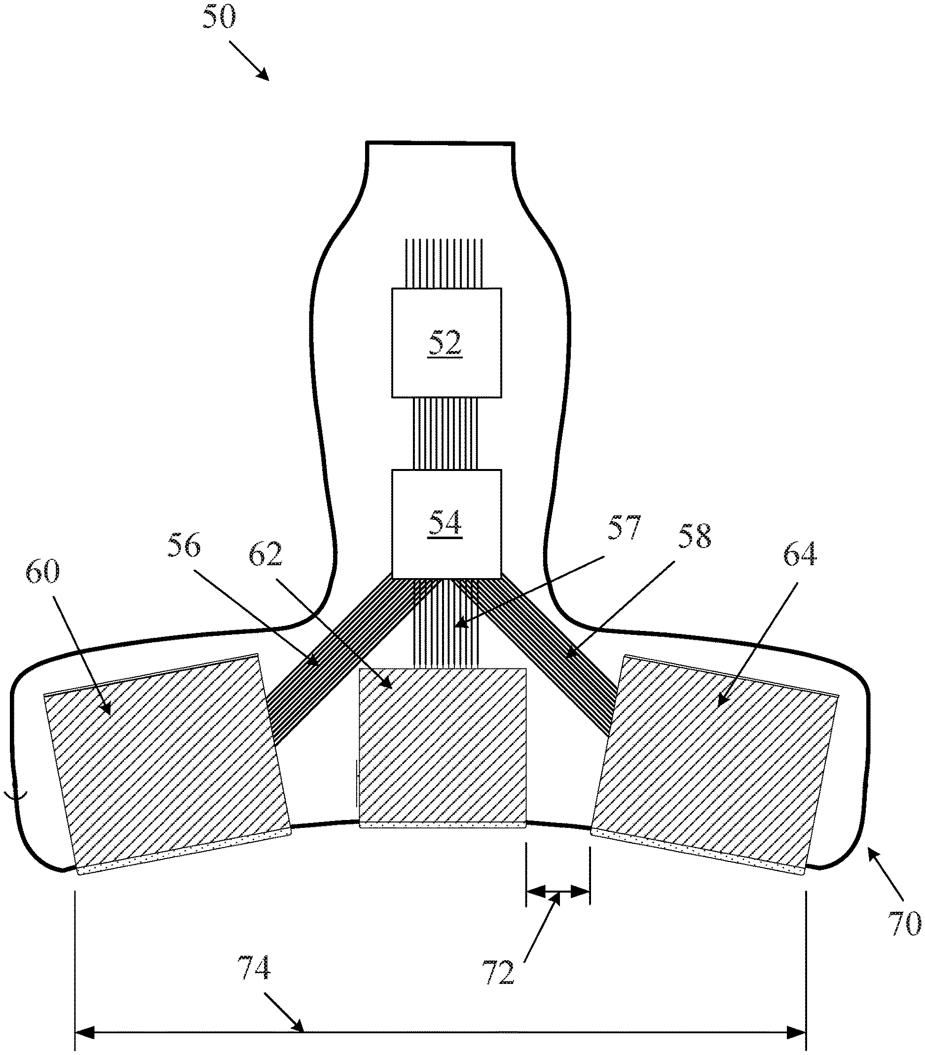
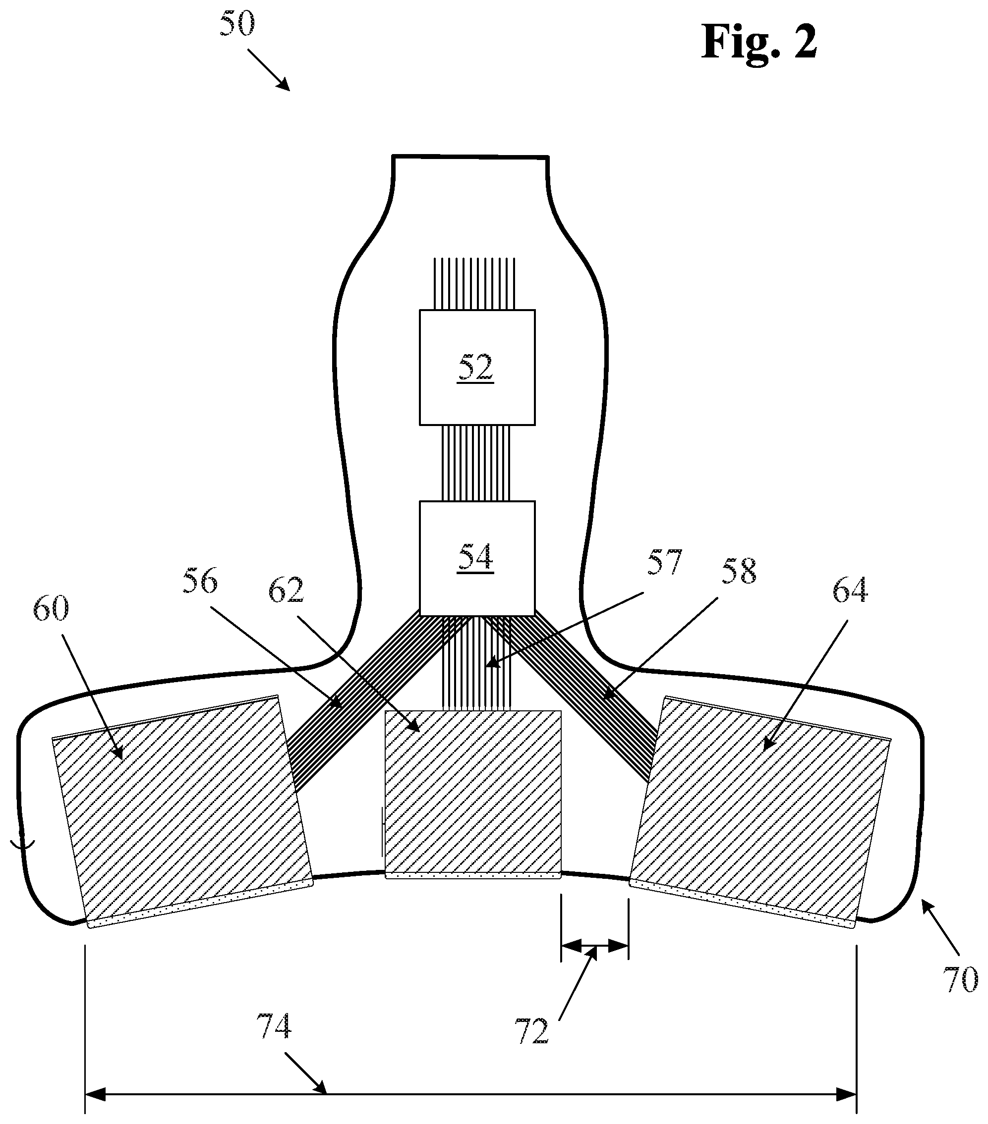
FIG. 2 is a section view of a multiple aperture ultrasound imaging probe.
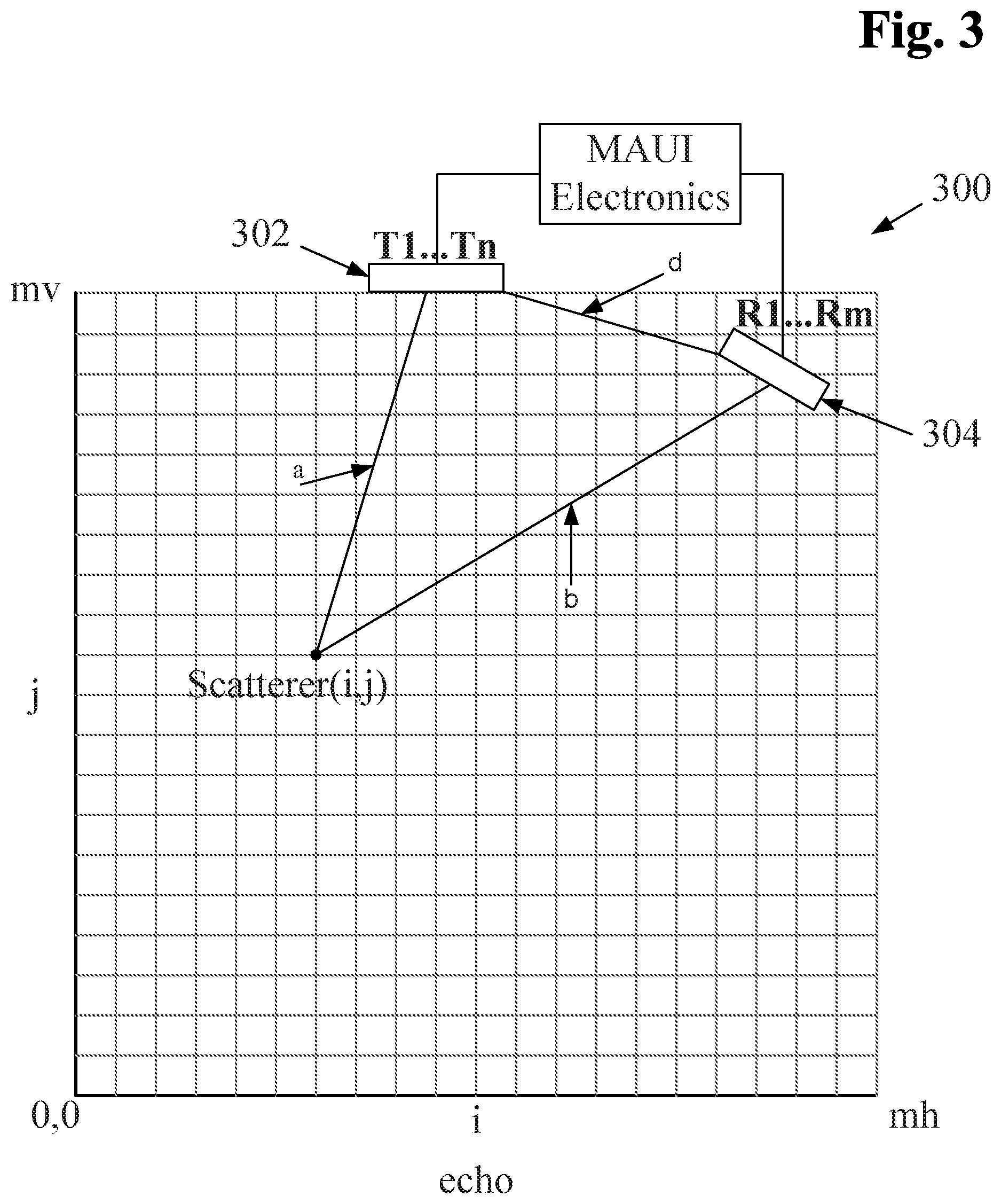
FIG. 3 is a schematic illustration of a multiple aperture ultrasound imaging process using a point-source transmit signal.
FIG. 4A is an illustration of a B-mode ultrasound image with an M-mode path defined through a portion of an imaged object.
FIG. 4B is an illustration of an M-mode graph of the data along the M-mode path of FIG. 4A.
FIG. 5A is an illustration of a B-mode ultrasound image with multiple M-mode paths defined through a portion of an imaged object.
FIG. 5B is an illustration of an M-mode graph of the data along the multiple m-mode paths of FIG. 5A.
DETAILED DESCRIPTION
In traditional ultrasound systems, images are generated by combining echoes from a series of pulses transmitted as phased array scan lines. In such scanline-based ultrasound imaging systems, the coordinate system used by the user interface usually lies along the scan lines. As a result, in such systems, a user interface for selecting an M-mode line typically involves selecting a desired segment of one of the scan lines. However, requiring the use of scan lines as M-mode lines means that the sonographer must position and hold the probe such that at least one of the scanlines intersects an anatomical feature through which an M-mode line is desired. In practice, this may be difficult and/or time consuming, and may limit the field of view.
Embodiments below provide systems and methods for obtaining M-mode data substantially in real-time along an arbitrary and/or user-defined path that does not necessarily lie along an ultrasound scan line. In some embodiments, the path may be a one-dimensional straight line. In other embodiments, the path may comprise a zig-zag pattern, a curved path, or any other non-linear path. As used herein the term "one-dimensional" may refer to a narrow path, whether linear, curved, or otherwise shaped. In some embodiments, a one-dimensional path may have a width of a single display pixel. In other embodiments, a one-dimensional path may have a width greater than one display pixel (e.g., 2 or 3 pixels), but may still have a length that is substantially greater than its width. As will be clear to the skilled artisan, the relationship between actual dimensions of represented objects and image pixels may be any value defined by the imaging system. In some embodiments, the M-mode path is not necessarily a straight line, and may include components at any orientation within the scan plane.
In some embodiments, an ultrasound imaging system may be configured to obtain three-dimensional (3D) image data, in which case an M-mode path may be selected from a displayed 3D volume. For example, an M-mode path may be defined in a 3D volume by selecting a desired plane through the 3D volume, and then defining an M-mode path within the selected 2D plane using any of the systems and methods described herein.
Some embodiments of systems and methods for specifying and displaying arbitrary M-mode lines may be used in conjunction with ping-based and/or multiple aperture ultrasound imaging systems. In other embodiments, systems and methods for specifying and displaying arbitrary M-mode lines as shown and described herein may also be used in conjunction with scanline-based imaging systems.
Ultrasound Imaging System Components
FIG. 1A is a block diagram illustrating components of an ultrasound imaging system that may be used with some embodiments of M-mode imaging systems and methods. The ultrasound system 10 of FIG. 1A may be particularly suited for scanline-based imaging and may be configured for acquiring real-time cardiac images either as 2D tomographic slices or as volumetric image data. The system may include a central controller/processor configured to control the other system components, including the probe 12 which includes one or more transducer arrays, elements of which may transmit and/or receive ultrasound signals. In some embodiments, the transducer array(s) may include a 1 D, 2D or other dimensional arrays formed from any suitable transducer material. The probe may generally be configured to transmit ultrasonic waves and to receive ultrasonic echo signals. In some embodiments, such transmission and reception may be controlled by a controller which may include a beamformer 14. The echo information from the beamformer 14 may then be processed by a B-mode processor 20 and/or other application-specific processors as needed (e.g., Doppler processors, contrast signal processors, elastography processors, etc.).
The B-Mode processor 20 may be configured to perform functions that include but are not limited to filtering, frequency and spatial compounding, harmonic data processing and other B-Mode functions. In some embodiments, the processed data may then be passed through a scan converter 24 configured to geometrically correct the data from a linear or polar geometry used by a phased-array scanning probe into a Cartesian format (x,y or x,y,z) with appropriate scaling in each dimension. In some embodiments, such as the embodiment described below with reference to FIGS. 2 and 3, a scan converter 24 may be omitted from the system.
Data for each 2D image or 3D volume may then be stored in a memory 28. The memory 28 may be volatile and/or non-volatile memory configured to store a few seconds up to several minutes or more of 2D or 3D echo image data. The video processor 26 may be configured to take the echo data stored in memory 28 and instructions from the central controller 16 to form video images, including any added graphic overlays and/or text annotation (e.g., patient information). Processed video data may then be passed on to the display 30 for presentation to the operator. The central controller 16 can direct the video processor 26 to display the most recently acquired data in memory as a real-time display, or it can replay sequences of older stored 2D slice or 3D volume data.
An M-mode processor 235 may also be provided to receive a definition of an M-mode path from a user interface and to form the images displaying the selected M-mode data in a desired output format. In some embodiments, an M-mode processor 235 may also include a (volatile or non-volatile) memory device for storing the defined M-mode path. In some embodiments, an M-mode processor 235 may be logically positioned between the video processor 26 and the display 30 in the diagram of FIG. 1A. In other embodiments, an M-mode processor 235 may be a set of functions built into the video processor 26 or another component of the system.
FIG. 1B illustrates another embodiment of an ultrasound imaging system 200 comprising an ultrasound probe 202 which may include a plurality of individual ultrasound transducer elements, some of which may be designated as transmit elements, and others of which may be designated as receive elements. In some embodiments, each probe transducer element may convert ultrasound vibrations into time-varying electrical signals and vice versa. In some embodiments, the probe 202 may include any number of ultrasound transducer arrays in any desired configuration. A probe 202 used in connection with the systems and methods described herein may be of any configuration as desired, including single aperture and multiple aperture probes.
The transmission of ultrasound signals from elements of the probe 202 may be controlled by a transmit controller 204. Upon receiving echoes of transmit signals, the probe elements may generate time-varying electric signals corresponding to the received ultrasound vibrations. Signals representing the received echoes may be output from the probe 202 and sent to a receive subsystem 210. In some embodiments, the receive subsystem may include multiple channels, each of which may include an analog front-end device ("AFE") 212 and an analog-to-digital conversion device (ADC) 214. In some embodiments, each channel of the receive subsystem 210 may also include digital filters and data conditioners (not shown) after the ADC 214. In some embodiments, analog filters prior to the ADC 214 may also be provided. The output of each ADC 214 may be directed into a raw data memory device 220. In some embodiments, an independent channel of the receive subsystem 210 may be provided for each receive transducer element of the probe 202. In other embodiments, two or more transducer elements may share a common receive channel.
In some embodiments, an analog front-end device 212 (AFE) may perform certain filtering processes before passing the signal to an analog-to-digital conversion device 214 (ADC). The ADC 214 may be configured to convert received analog signals into a series of digital data points at some pre-determined sampling rate. Unlike most ultrasound systems, some embodiments of the ultrasound imaging system of FIG. 1B may then store digital data representing the timing, phase, magnitude and/or the frequency of ultrasound echo signals received by each individual receive element in a raw data memory device 220 before performing any further beamforming, filtering, image layer combining or other image processing.
In order to convert the captured digital samples into an image, the data into an image, the data may be retrieved from the raw data memory 220 by an image generation subsystem 230. As shown, the image generation subsystem 230 may include a beamforming block 232 and an image layer combining ("ILC") block 234. In some embodiments, a beamformer 232 may be in communication with a calibration memory 238 that contains probe calibration data. Probe calibration data may include information about the precise acoustic position, operational quality, and/or other information about individual probe transducer elements. The calibration memory 238 may be physically located within the probe, within the imaging system, or in location external to both the probe and the imaging system.
In some embodiments, after passing through the image generation block 230, image data may then be stored in an image buffer memory 236 which may store beamformed and (in some embodiments) layer-combined image frames. A video processor 242 within a video subsystem 240 may then retrieve image frames from the image buffer, and may process the images into a video stream that may be displayed on a video display 244 and/or stored in a video memory 246 as a digital video clip, e.g. as referred to in the art as a "cine loop".
An M-mode processor 235 may also be provided to receive a definition of an M-mode path from a user interface and to form the images displaying the selected M-mode data in a desired output format. In some embodiments, an M-mode processor 235 may also include a (volatile or non-volatile) memory device for storing the defined M-mode path. In some embodiments, an M-mode processor 235 may be logically positioned between the image buffer 236 and the video processor 242 in the diagram of FIG. 1B. In other embodiments, an M-mode processor 235 may be a set of functions built into the image generation subsystem 230 or the video processor 242 or any other suitable component of the system.
In some embodiments, raw echo data stored in a memory device may be retrieved, beamformed, processed into images, and displayed on a display using a device other than an ultrasound imaging system. For example, such a system may omit the probe 202, the transmit controller 204 and the receive sub-system 210 of FIG. 1B, while including the remaining components. Such a system may be implemented predominantly in software running on general purpose computing hardware. Such alternative processing hardware may comprise a desktop computer, a tablet computer, a laptop computer, a smartphone, a server or any other general purpose data processing hardware.
Introduction to Ping-Based Imaging
Some embodiments of ultrasound imaging systems to be used in combination with the systems and methods described herein may use point source transmission of ultrasound signals during the transmit pulse. An ultrasound wavefront transmitted from a point source (also referred to herein as a "ping") illuminates the entire region of interest with each circular or spherical wavefront. Echoes from a single ping received by a single receive transducer element may be beamformed to form a complete image of the insonified region of interest. By combining data and images from multiple receive transducers across a wide probe, and by combining data from multiple pings, very high resolution images may be obtained.
As used herein the terms "point source transmission" and "ping" may refer to an introduction of transmitted ultrasound energy into a medium from a single spatial location. This may be accomplished using a single ultrasound transducer element or combination of adjacent transducer elements transmitting together. A single transmission from one or more element(s) may approximate a uniform spherical wave front, or in the case of imaging a 2D slice, may create a uniform circular wavefront within the 2D slice. In some cases, a single transmission of a circular or spherical wavefront from a point source transmit aperture may be referred to herein as a "ping" or a "point source pulse" or an "unfocused pulse."
Point source transmission differs in its spatial characteristics from a scanline-based "phased array transmission" or a "directed pulse transmission" which focuses energy in a particular direction (along a scanline) from the transducer element array. Phased array transmission manipulates the phase of a group of transducer elements in sequence so as to strengthen or steer an insonifying wave to a specific region of interest.
Images may be formed from such ultrasound pings by beamforming the echoes received by one or more receive transducer elements. In some embodiments, such receive elements may be arranged into a plurality of apertures in a process referred to as multiple aperture ultrasound imaging.
Beamforming is generally understood to be a process by which imaging signals received at multiple discrete receptors are combined to form a complete coherent image. The process of ping-based beamforming is consistent with this understanding. Embodiments of ping-based beamforming generally involve determining the position of reflectors corresponding to portions of received echo data based on the path along which an ultrasound signal may have traveled, an assumed-constant speed of sound and the elapsed time between a transmit ping and the time at which an echo is received. In other words, ping-based imaging involves a calculation of distance based on an assumed speed and a measured time. Once such a distance has been calculated, it is possible to triangulate the possible positions of any given reflector. This distance calculation is made possible with accurate information about the relative positions of transmit and receive transducer elements. (As discussed in Applicants' previous applications referenced above, a multiple aperture probe may be calibrated to determine the acoustic position of each transducer element to at least a desired degree of accuracy.) In some embodiments, ping-based beamforming may be referred to as "dynamic beamforming."
A dynamic beamformer may be used to determine a location and an intensity for an image pixel corresponding to each of the echoes resulting from each transmitted ping. When transmitting a ping signal, no beamforming need be applied to the transmitted waveform, but dynamic beamforming may be used to combine the echoes received with the plurality of receive transducers to form pixel data.
The image quality may be further improved by combining images formed by the beamformer from one or more subsequent transmitted pings. Still further improvements to image quality may be obtained by combining images formed by more than one receive aperture. An important consideration is whether the summation of images from different pings or receive apertures should be coherent summation (phase sensitive) or incoherent summation (summing magnitude of the signals without phase information). In some embodiments, coherent (phase sensitive) summation may be used to combine echo data received by transducer elements located on a common receive aperture resulting from one or more pings. In some embodiments, incoherent summation may be used to combine echo data or image data received by receive apertures that could possibly contain cancelling phase data. Such may be the case with receive apertures that have a combined total aperture that is greater than a maximum coherent aperture width for a given imaging target.
As used herein the terms "ultrasound transducer" and "transducer" may carry their ordinary meanings as understood by those skilled in the art of ultrasound imaging technologies, and may refer without limitation to any single component capable of converting an electrical signal into an ultrasonic signal and/or vice versa. For example, in some embodiments, an ultrasound transducer may comprise a piezoelectric device. In some alternative embodiments, ultrasound transducers may comprise capacitive micromachined ultrasound transducers (CMUT). Transducers are often configured in arrays of multiple elements. An element of a transducer array may be the smallest discrete component of an array. For example, in the case of an array of piezoelectric transducer elements, each element may be a single piezoelectric crystal.
As used herein, the terms "transmit element" and "receive element" may carry their ordinary meanings as understood by those skilled in the art of ultrasound imaging technologies. The term "transmit element" may refer without limitation to an ultrasound transducer element which at least momentarily performs a transmit function in which an electrical signal is converted into an ultrasound signal. Similarly, the term "receive element" may refer without limitation to an ultrasound transducer element which at least momentarily performs a receive function in which an ultrasound signal impinging on the element is converted into an electrical signal. Transmission of ultrasound into a medium may also be referred to herein as "insonifying." An object or structure which reflects ultrasound waves may be referred to as a "reflector" or a "scatterer."
As used herein the term "aperture" refers without limitation to one or more ultrasound transducer elements collectively performing a common function at a given instant of time. For example, in some embodiments, the term aperture may refer to a group of transducer elements performing a transmit function. In alternative embodiments, the term aperture may refer to a plurality of transducer elements performing a receive function. In some embodiments, group of transducer elements forming an aperture may be redefined at different points in time.
Generating ultrasound images using a ping-based ultrasound imaging process means that images from an entire region of interest are "in focus" at all times. This is true because each transmitted ping illuminates the entire region, receive apertures receive echoes from the entire region, and the dynamic multiple aperture beamforming process may form an image of any part or all of the insonified region. In such cases, the maximum extent of the image may be primarily limited by attenuation and signal-to-noise factors rather than by the confined focus of a transmit or receive beamforming apparatus. As a result, a full-resolution image may be formed from any portion of a region of interest using the same set of raw echo data. As used herein, the term "image window" will be used to refer to a selected portion of an entire insonified region of interest that is being displayed at any given time. For example, a first image window may be selected to include an entire insonified area, and then a user may choose to "zoom in" on a smaller selected area, thereby defining a new image window. The user may then choose to zoom out or pan the image window vertically and/or horizontally, thereby selecting yet another image window. In some embodiments, separate simultaneous images may be formed of multiple overlapping or non-overlapping image windows within a single insonified region.
Embodiments of Multiple Aperture Ultrasound Imaging Systems and Methods
Applicant's prior U.S. patent application Ser. No. 11/865,501 filed Oct. 1, 2007, now U.S. Pat. No. 8,007,439, and U.S. patent application Ser. No. 13/029,907 ("the '907 application"), now U.S. Pat. No. 9,146,313, describe embodiments of ultrasound imaging techniques using probes with multiple apertures to provide substantially increased resolution over a wide field of view.
In some embodiments, a probe may include one, two, three or more apertures for ultrasound imaging. FIG. 2 illustrates one embodiment of a multiple aperture ultrasound probe which may be used for ultrasound imaging with a point source transmit signal. The probe of FIG. 2 comprises three transducer arrays 60, 62, 64, each one of which may be a 1D, 2D, CMUT or other ultrasound transducer array. In alternative embodiments, a single curved array may also be used, each aperture being defined logically electronically as needed. In still further embodiments, any single-aperture or multiple-aperture ultrasound imaging probe may also be used. As shown, the lateral arrays 60 and 64 may be mounted in a probe housing 70 at angles relative to the center array 62. In some embodiments, the angle .THETA. of the lateral arrays relative to the central array may be between zero and 45 degrees or more. In one embodiment, the angle .THETA. is about 30 degrees. In some embodiments, the right and left lateral arrays 60, 64 may be mounted at different angles relative to the center array 62. In some embodiments, the probe 50 of FIG. 2 may have a total width 74 substantially wider than 2 cm, and in some embodiments 10 cm or greater.
In some embodiments as shown in FIG. 2, separate apertures of the probe may comprise separate transducer arrays which may be physically separated from one another. For example, in FIG. 2, a distance 72 physically separates the center aperture 62 from the right lateral aperture 64. The distance 72 can be the minimum distance between transducer elements on aperture 62 and transducer elements on aperture 64. In some embodiments, the distance 72 may be equal to at least twice the minimum wavelength of transmission from the transmit aperture. In some embodiments of a multiple aperture ultrasound imaging system, a distance between adjacent apertures may be at least a width of one transducer element. In alternative embodiments, a distance between apertures may be as large as possible within the constraints of a particular application and probe design.
In some embodiments, a probe such as that illustrated in FIG. 2 may be used with an ultrasound imaging system such as that illustrated in FIG. 1 but omitting the scan converter. As will be described in more detail below, some embodiments of a point-source imaging method negate the need for a scan converter. The probe 50 may also include one or more sensors 52 and/or controllers 54 joined to an ultrasound imaging system and/or to the transducer arrays by cables 56, 57, 58. Embodiments of similar multiple aperture probes 50 are also shown and described in US Patent Publication No. 2010/0262013 and U.S. patent application Ser. No. 13/029,907, filed Feb. 17, 2011, now U.S. Pat. No. 9,146,313, both of which are incorporated herein by reference.
Embodiments of multiple aperture ultrasound imaging methods using a point-source transmit signal will now be described with reference to FIG. 3. FIG. 3 illustrates a probe 300 with a first aperture 302 and a second aperture 304 directed toward a region of interest represented by the grid below the probe. In the illustrated embodiment, the first aperture is used as a transmit aperture 302, and the second aperture 304 is used for receiving echoes. In some embodiments, an ultrasound image may be produced by insonifying an entire region of interest to be imaged with a point-source transmitting element in a transmit aperture 302, and then receiving echoes from the entire imaged plane on one or more receive elements (e.g., R1-Rm) in one or more receive apertures 304.
In some embodiments, subsequent insonifying pulses may be transmitted from each of the elements T1-Tn on the transmitting aperture 302 in a similar point-source fashion. Echoes may then be received by elements on the receive aperture(s) 302 after each insonifying pulse. An image may be formed by processing echoes from each transmit pulse. Although each individual image obtained from a transmit pulse may have a relatively low resolution, combining these images may provide a high resolution image.
In some embodiments, transmit elements may be operated in any desired sequential order, and need not follow a prescribed pattern. In some embodiments, receive functions may be performed by all elements in a receive array 302. In alternative embodiments, echoes may be received on only one or a select few elements of a receive array 302.
The data received by the receiving elements is a series of echoes reflected by objects within the target region. In order to generate an image, each received echo must be evaluated to determine the location of the object within the target region that reflected it (each reflected point may be referred to herein as a scatterer). For a scatterer point represented by coordinates (i,j) in FIG. 3, it is a simple matter to calculate the total distance "a" from a particular transmit element Tx to an element of internal tissue or target object T at (i,j), and the distance "b" from that point to a particular receive element. These calculations may be performed using basic trigonometry. The sum of these distances is the total distance traveled by one ultrasound wave.
Assuming the speed of the ultrasound waves traveling through the target object is known, these distances can be translated into time delays which may be used to identify a location within the image corresponding to each received echo. When the speed of ultrasound in tissue is assumed to be uniform throughout the target object, it is possible to calculate the time delay from the onset of the transmit pulse to the time that an echo is received at the receive element. Thus, a given scatterer in the target object is the point for which a+b=the given time delay. The same method can be used to calculate delays for all points in the desired target to be imaged, creating a locus of points. As discussed in more detail in the '907 application, adjustments to time delays may be made in order to account for variations in the speed of sound through varying tissue paths.
A method of rendering the location of all of the scatterers in the target object, and thus forming a two dimensional cross section of the target object, will now be described with reference to FIG. 3 which illustrates a grid of points to be imaged by apertures 302 and 304. A point on the grid is given the rectangular coordinates (i,j). The complete image will be a two dimensional array of points provided to a video processing system to be displayed as a corresponding array of pixels. In the grid of FIG. 3, `mh` is the maximum horizontal dimension of the array and `mv` is the maximum vertical dimension. FIG. 3 also illustrates MAUI electronics, which can comprise any hardware and/or software elements as needed, such as those described above with reference to FIG. 1.
In some embodiments, the following pseudo code may be used to accumulate all of the information to be gathered from a transmit pulse from one transmit element (e.g., one element of T1 . . . Tn from aperture 302), and the consequent echoes received by one receive element (e.g., one element of R1 . . . Rm from aperture 304) in the arrangement of FIG. 3.
TABLE-US-00001 for (i = 0; i < mh; i++){ for (j = 0;j < mv; j++){ compute distance a compute distance b compute time equivalent of a+b echo[ i ][ j ] = echo[i ][ j]+stored received echo at the computed time } }
A complete two dimensional image may be formed by repeating this process for every receive element in a receive aperture 304 (e.g., R1 . . . Rm). In some embodiments, it is possible to implement this code in parallel hardware resulting in real time image formation.
In some embodiments, image quality may be further improved by combining similar images resulting from pulses from other transmit elements. In some embodiments, the combination of images may be performed by a simple summation of the single point source pulse images (e.g., coherent addition). Alternatively, the combination may involve taking the absolute value of each element of the single point source pulse images first before summation (e.g., incoherent addition). Further details of such combinations, including corrections for variations in speed-of-sound through different ultrasound paths, are described in Applicant's prior US Patent Applications referenced above.
As discussed above, because embodiments of an imaging system using a point source transmit signal and a multiple-aperture receive probe are capable of receiving an entire scan-plan image in response to a single insonifying pulse, a scan converter is not needed, and may therefore be omitted from an ultrasound imaging system. Having received a series of image frames in a similar manner, the image data may be processed and sent to a display for viewing by an operator. In addition to ultrasound imaging systems using point-source transmit signals, the following methods of selecting and displaying arbitrary m-mode paths may also be used with any other ultrasound imaging system, including phased array transmit systems, single-aperture probes, 3D probes, and probes in systems using synthetic aperture techniques.
Embodiments for Defining and Displaying Arbitrary M-Mode Paths
FIG. 4A illustrates an example of an ultrasound image with a specified m-mode path 100 drawn through an imaged object 110. The amplitude of each pixel along the m-mode path may be displayed in a graph (e.g., a bar graph, line graph or any other desired format). Changing pixel amplitude values may be illustrated over time. FIG. 4B illustrates an example of a graph of data taken along the m-mode path 100 of FIG. 4A.
In some embodiments, a sonographer may wish to simultaneously view changes along two or more separate M-mode paths. Thus in some embodiments, a user may define a plurality of M-mode paths 110, 112 as shown in FIG. 5A. The change in pixel values lying along the first and second paths 110, 112 may be displayed simultaneously in a pair of amplitude/time charts as shown for example in FIG. 5B. FIG. 5A also shows an example of a non-linear path 112. As discussed in further detail below, a non-linear M-mode path may have any length and shape as desired.
Multiple discontinuous M-mode paths and/or non-linear M-mode paths may be beneficial in viewing movement of multiple structures simultaneously. For example, a curve M-mode path may be beneficial when imaging anatomic structures such as a moving valve, such as a tricuspid valve, an aortic valve or a mitral valve. In other embodiments, multiple simultaneous but discontinuous m-mode lines may be used to simultaneously view the movement of multiple structures. For example, a first m-mode path may be drawn to view operation of a tricuspid valve, and a second M-mode path may be drawn to view operation of a mitral valve. Viewing the function of both valves simultaneously may provide substantial diagnostic benefits, such as allowing for precise calibration of a pacemaker.
Selection of an M-mode path generally involves identifying a group of image pixel locations which are to be presented over time as an M-mode graph. Identifying a group of pixels for an m-mode path may comprise identifying the coordinates of selected pixels in a coordinate system used by the video processing system. In some embodiments, M-mode selection and display methods as described herein may be performed in real-time using an ultrasound imaging system such as those illustrated in FIGS. 1A and 1B. With reference to FIGS. 1A and 1B, selection of an M-mode path may be performed by a user via a suitable user interface interaction performed in communication with the M-mode processor 235. The identification of selected pixels may be at least temporarily stored in a memory device associated with the M-mode processor 235. The selected pixels defining the M-mode path may then be retrieved from image frames in the image buffer and/or in the video processor, and an M-mode graph or image illustrating the values of the selected pixels may be formed by the M-mode processor 235 and transmitted to the display to be displayed along with the B-mode image. In alternative embodiments, M-mode selection and display methods as described herein may be performed on a workstation playing back stored 2D or 3D image data.
In some embodiments, selection of a group of pixel locations for presentation as an M-mode path may be assisted by or entirely performed automatically, such as by using a computer aided detection (CAD) system configured to identify a desired anatomical or other feature through which an m-mode path may be desired. For example, US Publication No. 2011/0021915 describes a system for automatic detection of structures in M-mode ultrasound imaging. In other embodiments, a desired M-mode path may be chosen by a user through any of several possible user interface interactions, several examples of which are provided below.
As will be clear to the skilled artisan, an imaging system or an image display system may include a variety of user interface devices through which a user may input information to or modify information or objects in a displayed image. Such user interface devices may comprise any of the following, trackballs, buttons, keys, keypads, sliders, dials, voice commands, touch screen, joystick, mouse, etc. The use of these and other user input devices will be clear to the skilled artisan.
In some embodiments, any arbitrary line or path in the image plane may be selected by a user as a line for M-mode display. In some embodiments, a linear path of defined length may be selected as an m-mode path. This may be facilitated through a number of user interface interactions, some examples of which are provided below.
In some embodiments, the ultrasound display may include a touch screen, and a user may define an M-mode path by simply drawing the desired path with a finger or stylus directly on the display screen. In other embodiments, a user may draw a freehand path using a separate user interface device such as a mouse or a drawing tablet. In some embodiments, after drawing a path of a desired shape, an M-mode path of the desired shape may be dragged across a display and/or rotated to a desired position.
In one embodiment of a user interface interaction, a linear m-mode path segment may be selected by first defining a line length, then defining a rotation angle, and then translating the line into a desired position. In some embodiments, further adjustments to the line length, rotation angle, and position may be made as needed. In some embodiments, defining a line length may comprise entering a numeric value with a numeric keypad or increasing/decreasin
References
D00000
D00001
D00002
D00003
D00004
D00005
D00006
XML
uspto.report is an independent third-party trademark research tool that is not affiliated, endorsed, or sponsored by the United States Patent and Trademark Office (USPTO) or any other governmental organization. The information provided by uspto.report is based on publicly available data at the time of writing and is intended for informational purposes only.
While we strive to provide accurate and up-to-date information, we do not guarantee the accuracy, completeness, reliability, or suitability of the information displayed on this site. The use of this site is at your own risk. Any reliance you place on such information is therefore strictly at your own risk.
All official trademark data, including owner information, should be verified by visiting the official USPTO website at www.uspto.gov. This site is not intended to replace professional legal advice and should not be used as a substitute for consulting with a legal professional who is knowledgeable about trademark law.