Sandal or slip-on footwear with improved optional-use heel strap and related methods
Arnold
U.S. patent number 10,617,170 [Application Number 16/450,835] was granted by the patent office on 2020-04-14 for sandal or slip-on footwear with improved optional-use heel strap and related methods. The grantee listed for this patent is Stephen Arnold. Invention is credited to Stephen Arnold.


| United States Patent | 10,617,170 |
| Arnold | April 14, 2020 |
Sandal or slip-on footwear with improved optional-use heel strap and related methods
Abstract
Disclosed is slip-on footwear with a concealable heel strap that is padded. Suitably, the padding of the padded heel strap is convertible into a pull-tab whenever the heel strap is concealed.
| Inventors: | Arnold; Stephen (San Diego, CA) | ||||||||||
|---|---|---|---|---|---|---|---|---|---|---|---|
| Applicant: |
|
||||||||||
| Family ID: | 70223406 | ||||||||||
| Appl. No.: | 16/450,835 | ||||||||||
| Filed: | June 24, 2019 |
Related U.S. Patent Documents
| Application Number | Filing Date | Patent Number | Issue Date | ||
|---|---|---|---|---|---|
| 29695000 | Jun 14, 2019 | ||||
| Current U.S. Class: | 1/1 |
| Current CPC Class: | A43B 11/00 (20130101); A43B 3/126 (20130101); A43B 3/0073 (20130101); A43B 3/122 (20130101); A43B 3/242 (20130101) |
| Current International Class: | A43B 3/24 (20060101); A43B 3/12 (20060101); A43B 3/00 (20060101) |
References Cited [Referenced By]
U.S. Patent Documents
| 366266 | July 1887 | Smithers |
| 430982 | June 1890 | Ziegler |
| 459616 | September 1891 | Von Rohonczy |
| 736194 | August 1903 | Bassett |
| 950862 | March 1910 | Nelson |
| 1110362 | September 1914 | Whitaker |
| 1908433 | July 1931 | Manville |
| 2024729 | December 1935 | Gustin |
| 2112761 | March 1938 | Buehner |
| 2233544 | March 1941 | McKinley |
| D132630 | June 1942 | Pfeiffer |
| 2390685 | December 1945 | Benson |
| D147308 | August 1947 | Steel |
| 2491297 | December 1949 | Brown |
| 2724913 | November 1955 | Russel |
| 2736110 | February 1956 | Hardinnon |
| 2741039 | April 1956 | Mathews |
| 3001302 | September 1961 | Farley |
| 3011281 | December 1961 | King |
| 3047967 | August 1962 | Hoyt et al. |
| 3121962 | February 1964 | Gullo |
| 3290802 | December 1966 | Fukuoka |
| 3336683 | August 1967 | Schellkopf |
| 3978596 | September 1976 | Brown et al. |
| 4017987 | April 1977 | Perez, Jr. et al. |
| 4026047 | May 1977 | Ahmer |
| 4051610 | October 1977 | Shigeji |
| D260047 | August 1981 | Heinz |
| 4461288 | July 1984 | Curtis |
| 4489509 | December 1984 | Libit |
| 4530171 | July 1985 | Zabala |
| 4756097 | July 1988 | Sanders |
| 4813162 | March 1989 | Harris |
| D305176 | December 1989 | Campbell |
| 4920664 | May 1990 | McGregor et al. |
| 5090140 | February 1992 | Sessa |
| 5205071 | April 1993 | Hergenroeder |
| 5228216 | July 1993 | Sargeant |
| D338320 | August 1993 | Haggar |
| D374335 | October 1996 | Grimes |
| 5615496 | April 1997 | Sharpstein |
| 5651195 | July 1997 | Clancy |
| 6237249 | May 2001 | Aguerre |
| D448146 | September 2001 | Jacobs |
| D452363 | December 2001 | Mansour |
| D453987 | March 2002 | Ray |
| D465642 | November 2002 | Petrovski |
| D465906 | November 2002 | Petrovski |
| D495855 | September 2004 | Comeau |
| D503271 | March 2005 | Choi |
| D508306 | August 2005 | Armado |
| D516280 | March 2006 | Jarmon Mouchi et al. |
| D523214 | June 2006 | Jarmon Mouchi et al. |
| D525417 | July 2006 | Kelsey |
| D529690 | October 2006 | Choi |
| D556992 | December 2007 | Choi |
| D560346 | January 2008 | Belley et al. |
| D562535 | February 2008 | Giorgio |
| 7331122 | February 2008 | Januszewski |
| 7439837 | October 2008 | McDonald |
| D594220 | June 2009 | McDaniel |
| D596834 | July 2009 | Tatsuno |
| D619795 | July 2010 | McBride |
| D623839 | September 2010 | Leleu |
| 7823299 | November 2010 | Brigham |
| 7854638 | December 2010 | Twombly |
| D634105 | March 2011 | Cheshire et al. |
| D635757 | April 2011 | Ward et al. |
| 7980004 | July 2011 | Klavano |
| D654671 | February 2012 | Coleman |
| D665155 | August 2012 | Arnold |
| D694995 | December 2013 | Nguyen |
| 9675132 | June 2017 | Marshall |
| 9820527 | November 2017 | Pratt |
| 9993045 | June 2018 | Graffeo |
| 10159310 | December 2018 | Sullivan |
| D838467 | January 2019 | Hughes |
| 2001/0011430 | August 2001 | Davis |
| 2006/0075656 | April 2006 | Januszewski |
| 2006/0090374 | May 2006 | Hillyer |
| 2007/0283594 | December 2007 | Sink |
| 2008/0155860 | July 2008 | Tai |
| 2008/0168682 | July 2008 | Le |
| 2008/0189984 | August 2008 | Januszewski |
| 2010/0107451 | May 2010 | Kay |
| 2011/0016751 | January 2011 | Somerville |
| 2011/0056091 | March 2011 | Shmurak et al. |
| 2011/0138518 | June 2011 | Bhalla |
| 2013/0291402 | November 2013 | Bell |
| 2017/0055630 | March 2017 | Marshall |
| 2017/0181493 | June 2017 | Graffeo |
| 2018/0289102 | October 2018 | Graffeo |
Assistant Examiner: Nguyen; Bao-Thieu L
Attorney, Agent or Firm: Buche & Associates, P.C. Johnson; Bryce A. Buche; John K.
Claims
I claim:
1. A method of wearing a slip-on sandal comprising the steps of: ensuring that the slip-on sandal comprises: an upper; a sole with a strap channel and a hole; a padded optional use strap that is provided to the strap channel and the hole; wherein the padded optional use strap is outfitted with a heel padding that is disposed in the strap channel; wherein the heal padding is reverse folded into two pull-tabs and the padded optional use strap is disposed through the hole and within the strap channel so that the two pull-tabs are extended from the strap channel; placing a foot within the upper and above the sole; gripping the two pull tabs; removing the optional use strap and the heel padding from the strap channel by pulling the tab; unfolding the heel padding by pulling one of the two pull tabs; pivoting the heel padding around the hole via the padded optional use strap so that the heel padding is positioned over a heel; placing the heel padding on the heel of the foot so that the heal padding is spaced from the sole; gripping the heel padding and pulling the pull heel padding away from the heel of the foot; disposing the padded optional use strap and a central portion of the heel padding into the strap channel; contacting a top side of the heel padding with an upper edge of the strap channel so that the top side of the heel padding remains reverse folded to create a first pull tab that extends from the strap channel while the top side of the heel padding is in contact with the upper edge of the strap channel contacting a bottom side of the heel padding with a lower edge of the strap channel so that the bottom side of the heel padding remains reverse folded to form a second pull tab that extends from the strap channel while the bottom side of the heel padding is in contact with the bottom edge of the strap channel; and, removing the foot from the upper and off of the sole.
2. The method of claim 1 wherein the sole is shaped like a human foot, the strap channel is defined in the periphery of a heel portion of the sole and the padded optional use strap is secured by partially being strung through the sole.
3. The method of claim 2 wherein the upper is defined by a toe hole and a foot strap.
4. The method of claim 3 wherein the strap channel holds the heel padding in a reverse fold so that the heel padding is retained within the strap channel while it is inside out.
5. The method of claim 4 wherein the optional use strap is made of rubber and outfitted with padding that sits flush to the sole when stored forward or backward in the sole.
Description
CROSS-REFERENCE TO RELATED APPLICATIONS
Not applicable.
STATEMENT REGARDING FEDERALLY SPONSORED RESEARCH OR DEVELOPMENT
Not applicable.
THE NAMES OF THE PARTIES TO A JOINT RESEARCH AGREEMENT
Not applicable.
REFERENCE TO AN APPENDIX SUBMITTED ON A COMPACT DISC AND INCORPORATED BY REFERENCE OF THE MATERIAL ON THE COMPACT DISC
Not applicable.
STATEMENT REGARDING PRIOR DISCLOSURES BY THE INVENTOR OR A JOINT INVENTOR
Reserved for a later date, if necessary.
BACKGROUND OF THE INVENTION
Field of Invention
The disclosed subject matter is in the field of sandal or slip-on footwear.
Background of the Invention
Slip-on sandals, like flip-flops (e.g., FIG. 1, U.S. Des. Pat. D793,041 (issued Aug. 1, 2017)) or Crocs.RTM. (e.g., FIG. 1, U.S. Des. Pat. D535,088 (issued Jan. 16, 2007)), are a stylish and cozy style of footwear. However, slip-on sandals are typically not secured to a user's heel and, as a result, this style of footwear can either make it difficult for a user to make abrupt and complicated footsteps or else easily slip-off during undesirable circumstances. So, some slip-on sandals are provided with an optional-use heel-strap.
One type of optional use heel-strap for slip-on sandals is shown in FIG. 8 of U.S. Des. Pat. D838,467 (issued Jan. 22, 2019). The optional-use heel strap shown in that document is simply stuck to the midsole of a slip-on sandal and provided over a user's heel whenever its utility is desirable. A similar optional-use heel strap that is stuck through a slip-on sandal's upper is shown in FIG. 1 of U.S. D694,994 (issued Dec. 10, 2013). Unfortunately, this type of optional-use heel strap can damage the slip-on sandal and is, therefore, not entirely satisfactory in all situations. This type of strap has other drawbacks too, like, the inability of a user to hide the strap once the strap is placed on the slip-on and the potential for injury if the strap is placed on the slip on in an incorrect manner.
Another type of optional-use heel strap for slip-on sandals (like Crocs.RTM.) is shown in FIG. 3 of U.S. D732,808 (issued Jun. 30, 2015). The optional-use heel strap shown in that document is coupled to the upper and placed in a heel position when its utility is desired or else simply rotated out of the way over the sandal's upper when not needed. This type of optional-use heel strap can change the aesthetic appearance of the sandal and is, therefore, not entirely satisfactory in situations where a heel strap is wanted without a corresponding change in the sandal's appearance. Also, this type of heel strap is attached with a metal grommet which can be uncomfortable or rust.
Yet another type of optional-use heel strap for slip-on sandals (like flip flops or Crocs.RTM.) is shown in the figures of U.S. Published Pat. App. US2008/0189984 (published Aug. 14, 2008). This type of optional use heel strap is concealed in the sole of a sandal whenever the heel strap is not needed and otherwise exposed when its utility is desirable. A more elaborate version of this type of optional use heel strap is shown in the figures of U.S. Pat. No. 7,823,299 (issued Nov. 2, 2010). This type of optional-use heel strap can be uncomfortable and therefore unsatisfactory in some situations since it is not always possible to conceal a sufficiently padded heel strap in the sole of a slip-on sandal. Also, these types of heel-straps are difficult to reveal once put in a concealed configuration.
SUMMARY OF THE INVENTION
In view of the foregoing, an object of this specification is to disclose slip-on footwear with an improved optional-use heel strap. It is a further objective of this disclosure to provide an optional use heel strap to slip-on footwear without damaging the footwear. It is another objective of this specification to describe footwear with a heel strap that can be used or not used without substantially altering the aesthetic appearance of the footwear. Finally, it is an objective of this disclosure to highlight slip-on footwear with a concealable heel strap that is heavily padded.
In one embodiment, slip-on footwear includes a sole, an upper, and a padded optional-use heel strap concealed within a strap channel disposed around the heel portion of the sole; wherein, the padded portion of the heel strap is folded in half to define a pull-tab that extends from the strap channel of sole for a user to grip the pull-tab to release the strap from the strap channel.
In one mode of use, the slip-on footwear is provided to a foot of a wearer, the pull-tab is pulled to expose the heel-strap, the pull-tab is unfolded to define padding for the strap, and strap is placed over the heel of a wearer with the padding provided to the wearer's heel.
In another mode of use, a wearer of the slip-on footwear pulls the padding of the strap off of the user's heel, folds the padding to define the pull tab, and deposits the heel strap in the strap channel of the sole of the slip-on footwear.
BRIEF DESCRIPTION OF THE SEVERAL VIEWS OF THE DRAWINGS
Other objectives of the disclosure will become apparent to those skilled in the art once the invention has been shown and described. The manner in which these objectives and other desirable characteristics can be obtained is explained in the following description and attached figures in which:
FIG. 1 is a side view of a sandal;
FIG. 2 is a front view of a sandal;
FIG. 3 is a rear view of the sandal;
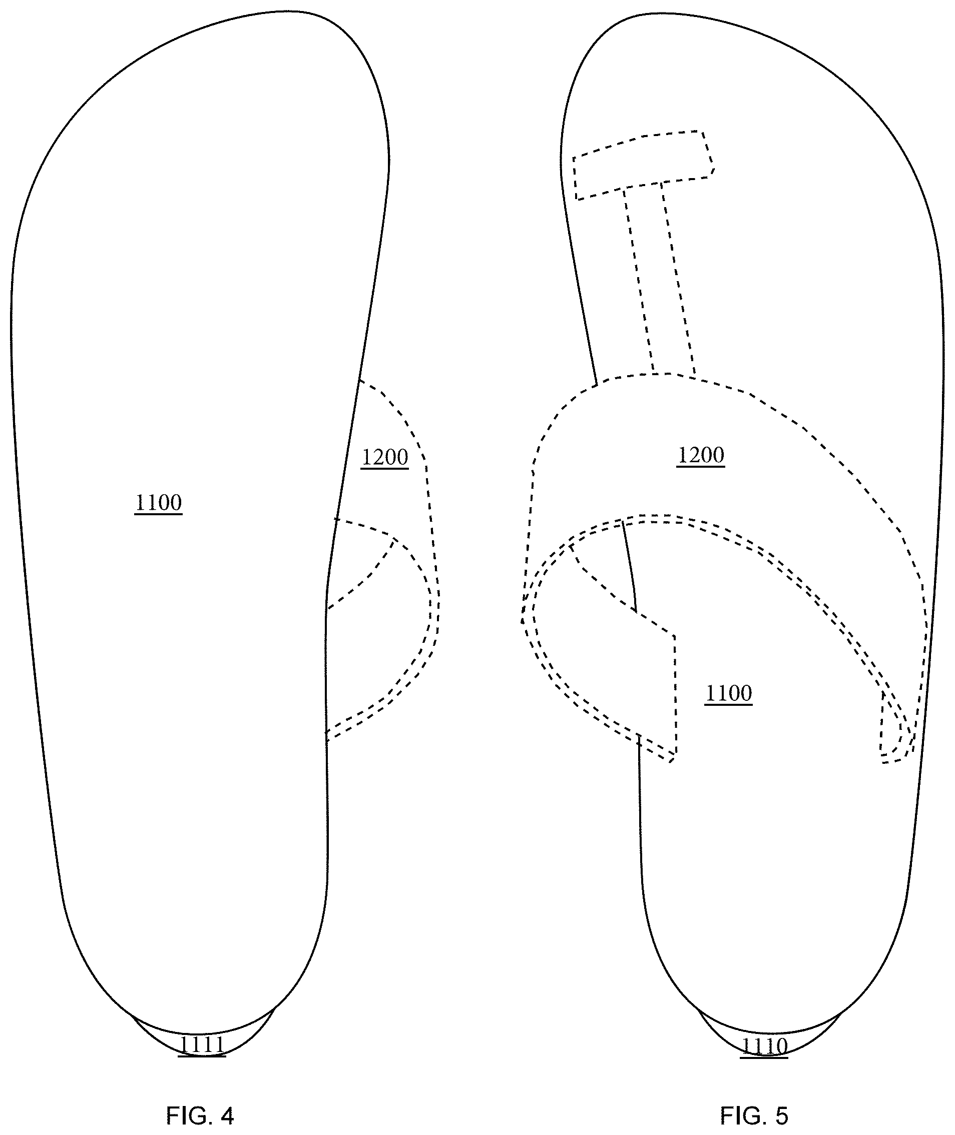
FIG. 4 is a bottom view of a sandal;
FIG. 5 is a top view of a sandal;
FIG. 6 is an environmental side view of the sandal in an alternate configuration;
FIG. 7 is an environmental front view of the sandal in the alternate configuration;
FIG. 8 is an environmental rear view of the sandal in the alternate configuration;
FIG. 9 is a side view of a sandal with the optional use heel strap removed; and,
FIG. 10 is a schematic of the optional use heel strap.
In the figures, the following components are associated with the adjacent reference numerals: 1000 slip-on sandal; 1100 sole 1110 optional use strap 1111 pull-tab 1112 heel padding 1120 strap channel 1121 hole 1200 upper
It is to be noted, however, that the appended figures illustrate only typical embodiments of this invention and are therefore not to be considered limiting of its scope, for the invention may admit to other equally effective embodiments that will be appreciated by those reasonably skilled in the relevant arts. Also, figures are not necessarily made to scale but are representative.
DETAILED DESCRIPTION OF PREFERRED EMBODIMENTS
Disclosed is slip-on footwear with a concealable heel strap that is padded. Suitably, the padding of the padded heel strap is convertible into a pull-tab whenever the heel strap is concealed. The other specifics of the disclosed slip-on footwear with a concealable heel strap are described with reference to the drawings.
FIG. 1 is a side view of a sandal 1000. FIG. 2 is a front view of the sandal 1000. FIG. 3 is a rear view of the sandal 1000. FIG. 4 is a bottom view of a sandal. FIG. 5 is a top view of a sandal. As shown in FIGS. 1 through 5, the sandal 1000 is comprises a sole 1100, an upper 1200, and a concealed strap 1110 with two pull-tabs 1111.
Still referring to FIGS. 1 through 5, the sole 1100 is best seen in FIGS. 1, 2, 3 and 4, the upper is best seen in FIGS. 1, 2, 3, and 5, and the heel strap 1110 is best seen in FIGS. 1 and 3. As shown, the sole 1110 is typically shaped like a human foot and defined by foam, rubber, or some combination thereof. As best seen in FIG. 4, the upper 1200 is provided to a top surface of the sole 1100. In the preferred embodiment, the upper is defined by a toe hole and a foot strap, the upper can be any type of slip-on known to those of skill in the art. As discussed below in connection with FIGS. 1 and 3, a heel strap 1110 is concealed in the sole 1100.
FIG. 6 is an environmental side view of the sandal in an alternate configuration where the heel strap 1110 is revealed. FIG. 7 is an environmental front view of the sandal in the alternate configuration. FIG. 8 is an environmental rear view of the sandal in the alternate configuration. As shown in FIGS. 6 through 8, the sandal 1000 in the alternate configuration comprises the sole 1100 with a strap channel, an upper 1200, and a revealed strap 1110 that has padding 1112.
Still referring to FIGS. 9 through 8, the sole 1100 is best seen in FIGS. 1, 2, 3 and 4, the upper is best seen in FIGS. 1, 2, 3, and 5, and the heel strap 1110 is best seen in FIGS. 1 and 3. As shown, the sole 1110 is still typically shaped like a human foot and features a strap channel 1120 disposed around the periphery of the heel portion of the sole 1100. As shown, a heel strap 1110 is revealed with padding 1112 positioned over a heel of a wearer.
Comparing FIGS. 1 through 5 through FIGS. 6 through 8, the strap 1110 can be concealed in the strap channel 1120 during periods of non-use or else be provided over the heel of a wearer during periods of use. Suitably, pull tab 1111 is accessible at the heel of the sole 1100 so that the strap may be removed from the strap channel 1120. Suitably, the padding 1112 is unfurled from the pull tabs 1111 after the strap 1110 is pulled out of the strap channel 1120. Once unfurled, the padding 1112 may be provided over the heel of a wearer.
FIG. 9 is a side view of a sandal with the optional use heel strap removed. As shown, the sole 1100 may be provided with a hole 1121 so that the strap may be fastened to the slip-on sandal 1000. Suitably, the hole may be provided through the sole 1100 or the sole may be split 1122 and the strap 1110 (not shown in FIG. 10) sandwiched into the strap channel 1120.
FIG. 10 is a schematic of the optional use heel strap 1110. As shown the padding 1112 may be unfurled in an upright position to define a cup-like heel pad. The padding 1112 may be reverse folded (e.g., by somewhat turning the cup-like heel pad inside out) to create at least one pull tab 1111. Suitably, the padding 1112 may feature a bias to a configuration of a heel pad wherein the strap channel defeats the bias to hold the padding in a folded state to expose the pull tabs. See, e.g., FIG. 1. In one embodiment, the strap is made of rubber or other elastomeric materials.
Although the method and apparatus is described above in terms of various exemplary embodiments and implementations, it should be understood that the various features, aspects and functionality described in one or more of the individual embodiments are not limited in their applicability to the particular embodiment with which they are described, but instead might be applied, alone or in various combinations, to one or more of the other embodiments of the disclosed method and apparatus, whether or not such embodiments are described and whether or not such features are presented as being a part of a described embodiment. Thus the breadth and scope of the claimed invention should not be limited by any of the above-described embodiments.
Terms and phrases used in this document, and variations thereof, unless otherwise expressly stated, should be construed as open-ended as opposed to limiting. As examples of the foregoing: the term "including" should be read as meaning "including, without limitation" or the like, the term "example" is used to provide exemplary instances of the item in discussion, not an exhaustive or limiting list thereof, the terms "a" or "an" should be read as meaning "at least one," "one or more," or the like, and adjectives such as "conventional," "traditional," "normal," "standard," "known" and terms of similar meaning should not be construed as limiting the item described to a given time period or to an item available as of a given time, but instead should be read to encompass conventional, traditional, normal, or standard technologies that might be available or known now or at any time in the future. Likewise, where this document refers to technologies that would be apparent or known to one of ordinary skill in the art, such technologies encompass those apparent or known to the skilled artisan now or at any time in the future.
The presence of broadening words and phrases such as "one or more," "at least," "but not limited to" or other like phrases in some instances shall not be read to mean that the narrower case is intended or required in instances where such broadening phrases might be absent. The use of the term "assembly" does not imply that the components or functionality described or claimed as part of the module are all configured in a common package. Indeed, any or all of the various components of a module, whether control logic or other components, might be combined in a single package or separately maintained and might further be distributed across multiple locations.
Additionally, the various embodiments set forth herein are described in terms of exemplary block diagrams, flow charts and other illustrations. As will become apparent to one of ordinary skill in the art after reading this document, the illustrated embodiments and their various alternatives might be implemented without confinement to the illustrated examples. For example, block diagrams and their accompanying description should not be construed as mandating a particular architecture or configuration.
All original claims submitted with this specification are incorporated by reference in their entirety as if fully set forth herein.
PAPER "SEQUENCE LISTING"
Not applicable.
* * * * *
D00000
D00001
D00002
D00003
D00004
XML
uspto.report is an independent third-party trademark research tool that is not affiliated, endorsed, or sponsored by the United States Patent and Trademark Office (USPTO) or any other governmental organization. The information provided by uspto.report is based on publicly available data at the time of writing and is intended for informational purposes only.
While we strive to provide accurate and up-to-date information, we do not guarantee the accuracy, completeness, reliability, or suitability of the information displayed on this site. The use of this site is at your own risk. Any reliance you place on such information is therefore strictly at your own risk.
All official trademark data, including owner information, should be verified by visiting the official USPTO website at www.uspto.gov. This site is not intended to replace professional legal advice and should not be used as a substitute for consulting with a legal professional who is knowledgeable about trademark law.