Rejection of false turns of rotary inputs for electronic devices
Shedletsky , et al.
U.S. patent number 10,613,685 [Application Number 16/262,728] was granted by the patent office on 2020-04-07 for rejection of false turns of rotary inputs for electronic devices. This patent grant is currently assigned to APPLE INC.. The grantee listed for this patent is Apple Inc.. Invention is credited to Colin M. Ely, Anna-Katrina Shedletsky, Samuel Weiss, Christopher M. Werner.


View All Diagrams
| United States Patent | 10,613,685 |
| Shedletsky , et al. | April 7, 2020 |
Rejection of false turns of rotary inputs for electronic devices
Abstract
Various embodiments for detecting and rejecting false, unintended rotations of rotary inputs of electronic devices are disclosed herein. In one example, an electronic device is provided with an optical detector that measures the distance between the electronic device and the wearer's forearm or hand, and when the distance is smaller than a threshold distance, the turns of the rotary input are false, unintended turns. In another example, a crown of a rotary input includes a plurality of capacitive sensors that detects the presence of a wearer's finger, which when absent, the turns of the rotary input are false turns. In another example, deflections or positions of a shaft of the rotary input are measured and if the deflections/positions indicate an upward force on the rotary input (which are likely caused by the wearer's forearm or hand), the turns of the rotary input are false turns. Other embodiments are described herein.
| Inventors: | Shedletsky; Anna-Katrina (Mountain View, CA), Werner; Christopher M. (San Jose, CA), Ely; Colin M. (Sunnyvale, CA), Weiss; Samuel (Los Altos, CA) | ||||||||||
|---|---|---|---|---|---|---|---|---|---|---|---|
| Applicant: |
|
||||||||||
| Assignee: | APPLE INC. (Cupertino,
CA) |
||||||||||
| Family ID: | 50280465 | ||||||||||
| Appl. No.: | 16/262,728 | ||||||||||
| Filed: | January 30, 2019 |
Prior Publication Data
| Document Identifier | Publication Date | |
|---|---|---|
| US 20190163324 A1 | May 30, 2019 | |
Related U.S. Patent Documents
| Application Number | Filing Date | Patent Number | Issue Date | ||
|---|---|---|---|---|---|
| 16048081 | Jul 27, 2018 | 10222909 | |||
| 15117819 | Aug 14, 2018 | 10048802 | |||
| PCT/US2014/016079 | Feb 12, 2014 | ||||
| Current U.S. Class: | 1/1 |
| Current CPC Class: | G06F 1/1626 (20130101); G06F 3/044 (20130101); G06F 3/0362 (20130101); G06F 3/0421 (20130101); G06F 1/163 (20130101); G06F 3/0418 (20130101); G06F 2203/04106 (20130101) |
| Current International Class: | G06F 3/041 (20060101); G06F 1/16 (20060101); G06F 3/0362 (20130101); G06F 3/042 (20060101); G06F 3/044 (20060101) |
References Cited [Referenced By]
U.S. Patent Documents
| 2237860 | April 1941 | Bolle |
| 2288215 | June 1942 | Taubert et al. |
| 2497935 | February 1950 | Feurer |
| 2771734 | November 1956 | Morf |
| 2788236 | April 1957 | Kafowi |
| 2797592 | July 1957 | Marrapese |
| 3040514 | June 1962 | Dinstman |
| 3056030 | September 1962 | Kelchner |
| 3130539 | April 1964 | Davis |
| 3355873 | December 1967 | Morf |
| 3362154 | January 1968 | Perret |
| 3410247 | November 1968 | Dronberger |
| 3495398 | February 1970 | Widmer et al. |
| 3577876 | May 1971 | Spadini |
| 3621649 | November 1971 | Vulcan et al. |
| 3662618 | May 1972 | Kroll et al. |
| 3733803 | May 1973 | Hiraga |
| 4007347 | February 1977 | Haber |
| 4031341 | June 1977 | Wuthrich et al. |
| 4037068 | July 1977 | Gaynor |
| 4077200 | March 1978 | Schneider |
| 4133404 | January 1979 | Griffin |
| 4170104 | October 1979 | Yamagata |
| 4258096 | March 1981 | LaMarche |
| 4287400 | September 1981 | Kitik |
| 4289400 | September 1981 | Kubola et al. |
| 4311026 | January 1982 | Ochoa |
| 4311990 | January 1982 | Burke |
| 4324956 | April 1982 | Sakakino et al. |
| 4345119 | August 1982 | Latasiewicz |
| 4364674 | December 1982 | Tesch |
| 4379642 | April 1983 | Meyrat |
| 4395134 | July 1983 | Luce |
| 4396298 | August 1983 | Ripley |
| 4417824 | November 1983 | Paterson et al. |
| 4520306 | May 1985 | Kirby |
| 4581509 | April 1986 | Sanford et al. |
| 4600316 | July 1986 | Besson |
| 4617461 | October 1986 | Subbarao et al. |
| 4634861 | January 1987 | Ching et al. |
| 4641026 | February 1987 | Garcia, Jr. |
| 4670737 | June 1987 | Rilling |
| 4766642 | August 1988 | Gaffney et al. |
| 4783772 | November 1988 | Umemoto et al. |
| 4884073 | November 1989 | Souloumiac |
| 4914831 | April 1990 | Kanezashi et al. |
| 4922070 | May 1990 | Dorkinski |
| 4931794 | June 1990 | Haag |
| 4952799 | August 1990 | Loewen |
| 4980685 | December 1990 | Souloumiac et al. |
| 4987299 | January 1991 | Kobayashi et al. |
| 5034602 | July 1991 | Garcia et al. |
| 5177355 | January 1993 | Branan |
| 5214278 | May 1993 | Banda |
| 5258592 | November 1993 | Nishikawa et al. |
| 5288993 | February 1994 | Bidiville et al. |
| 5347123 | September 1994 | Jackson et al. |
| 5383166 | January 1995 | Gallay |
| 5471054 | November 1995 | Watanabe |
| 5509174 | April 1996 | Worrell |
| 5572314 | November 1996 | Hyman et al. |
| 5583560 | December 1996 | Florin et al. |
| 5631881 | May 1997 | Pessey et al. |
| 5726645 | March 1998 | Kamon et al. |
| 5748111 | May 1998 | Bates |
| 5825353 | October 1998 | Will |
| 5841050 | November 1998 | Clift et al. |
| 5847335 | December 1998 | Sugahara et al. |
| 5867082 | February 1999 | Van Zeeland |
| 5943233 | August 1999 | Ebina |
| 5953001 | September 1999 | Challener et al. |
| 5960366 | September 1999 | Duwaer et al. |
| 5963332 | October 1999 | Feldman et al. |
| 5999168 | December 1999 | Rosenberg et al. |
| 6069567 | May 2000 | Zawilski |
| 6134189 | October 2000 | Carrard |
| 6154201 | November 2000 | Levin et al. |
| 6175679 | January 2001 | Veligdan et al. |
| 6241684 | June 2001 | Amano |
| 6246050 | June 2001 | Tullis et al. |
| 6252825 | June 2001 | Perotto |
| 6304247 | October 2001 | Black |
| 6355891 | March 2002 | Ikunami |
| 6361502 | March 2002 | Puolakanaho et al. |
| 6377239 | April 2002 | Isikawa |
| 6392640 | May 2002 | Will |
| 6396006 | May 2002 | Yokoji et al. |
| 6422740 | July 2002 | Leuenberger |
| 6477117 | November 2002 | Narayanaswami et al. |
| 6502982 | January 2003 | Bach et al. |
| 6525278 | February 2003 | Villain et al. |
| 6556222 | April 2003 | Narayanaswami |
| 6575618 | June 2003 | Inoue et al. |
| 6587400 | July 2003 | Line |
| 6646635 | November 2003 | Pogatetz et al. |
| 6661438 | November 2003 | Shiraishi et al. |
| 6672758 | January 2004 | Ehrsam et al. |
| 6794992 | September 2004 | Rogers |
| 6809275 | October 2004 | Cheng et al. |
| 6834430 | December 2004 | Worrell |
| 6846998 | January 2005 | Hasumi et al. |
| 6882596 | April 2005 | Guanter |
| 6888076 | May 2005 | Hetherington |
| 6896403 | May 2005 | Gau |
| 6909378 | June 2005 | Lambrechts et al. |
| 6914551 | July 2005 | Vidal |
| 6961099 | November 2005 | Takano et al. |
| 6963039 | November 2005 | Weng et al. |
| 6967903 | November 2005 | Guanter |
| 6977868 | December 2005 | Brewer et al. |
| 6982930 | January 2006 | Hung |
| 6985107 | January 2006 | Anson |
| 6987568 | January 2006 | Dana |
| 6998553 | February 2006 | Hisamune et al. |
| 7016263 | March 2006 | Gueissaz et al. |
| 7021442 | April 2006 | Borgerson |
| 7034237 | April 2006 | Ferri et al. |
| 7081905 | July 2006 | Raghunath et al. |
| 7102626 | September 2006 | Denny, III |
| 7111365 | September 2006 | Howie, Jr. |
| 7113450 | September 2006 | Plancon et al. |
| 7119289 | October 2006 | Lacroix |
| 7135673 | November 2006 | Saint Clair |
| 7167083 | January 2007 | Giles |
| 7244927 | July 2007 | Huynh |
| 7255473 | August 2007 | Hiranuma et al. |
| 7265336 | September 2007 | Hataguchi et al. |
| 7274303 | September 2007 | Dresti et al. |
| 7285738 | October 2007 | Lavigne et al. |
| 7286063 | October 2007 | Gauthey |
| 7292741 | November 2007 | Ishiyama et al. |
| 7358481 | April 2008 | Yeoh et al. |
| 7369308 | May 2008 | Tsuruta et al. |
| 7371745 | May 2008 | Ebright et al. |
| 7385874 | June 2008 | Vuilleumier |
| 7404667 | July 2008 | Born et al. |
| 7465917 | December 2008 | Chin et al. |
| 7468036 | December 2008 | Rulkov et al. |
| 7506269 | March 2009 | Lang et al. |
| 7520664 | April 2009 | Wai |
| 7528824 | May 2009 | Kong |
| 7545367 | June 2009 | Sunda et al. |
| 7591582 | September 2009 | Hiranuma et al. |
| 7593755 | September 2009 | Colando et al. |
| 7605846 | October 2009 | Watanabe |
| 7634263 | December 2009 | Louch et al. |
| 7646677 | January 2010 | Nakamura |
| 7655874 | February 2010 | Akieda |
| 7682070 | March 2010 | Burton |
| 7708457 | May 2010 | Girardin |
| 7710456 | May 2010 | Koshiba et al. |
| 7732724 | June 2010 | Otani et al. |
| 7761246 | July 2010 | Matsui |
| 7763819 | July 2010 | Ieda et al. |
| 7772507 | August 2010 | Orr |
| 7778115 | August 2010 | Ruchonnet |
| 7781726 | August 2010 | Matsui et al. |
| RE41637 | September 2010 | O'Hara et al. |
| 7791588 | September 2010 | Tierling et al. |
| 7791597 | September 2010 | Silverstein et al. |
| 7822469 | October 2010 | Lo |
| 7856255 | December 2010 | Tsuchiya et al. |
| 7858583 | December 2010 | Schmidt et al. |
| 7865324 | January 2011 | Lindberg |
| 7894957 | February 2011 | Carlson |
| 7946758 | May 2011 | Mooring |
| 8063892 | November 2011 | Shahoian et al. |
| 8138488 | March 2012 | Grot |
| 8143981 | March 2012 | Washizu et al. |
| 8167126 | May 2012 | Stiehl |
| 8169402 | May 2012 | Shahoian et al. |
| 8188989 | May 2012 | Levin et al. |
| 8195313 | June 2012 | Fadell et al. |
| 8229535 | July 2012 | Mensinger et al. |
| 8248815 | August 2012 | Yang et al. |
| 8263886 | September 2012 | Lin et al. |
| 8263889 | September 2012 | Takahashi et al. |
| 8294670 | October 2012 | Griffin et al. |
| 8312495 | November 2012 | Vanderhoff |
| 8368677 | February 2013 | Yamamoto |
| 8371745 | February 2013 | Manni |
| 8373661 | February 2013 | Lan et al. |
| 8410971 | April 2013 | Friedlander |
| 8432368 | April 2013 | Momeyer et al. |
| 8439559 | May 2013 | Luk et al. |
| 8441450 | May 2013 | Degner et al. |
| 8446713 | May 2013 | Lai |
| 8456430 | June 2013 | Oliver et al. |
| 8477118 | July 2013 | Lan et al. |
| 8493190 | July 2013 | Periquet et al. |
| 8508511 | August 2013 | Tanaka et al. |
| 8525777 | September 2013 | Stavely et al. |
| 8562489 | October 2013 | Burton et al. |
| 8568313 | October 2013 | Sadhu |
| 8576044 | November 2013 | Chapman |
| 8593598 | November 2013 | Chen et al. |
| 8607662 | December 2013 | Huang |
| 8614881 | December 2013 | Yoo |
| 8666682 | March 2014 | LaVigne et al. |
| 8677285 | March 2014 | Tsern et al. |
| 8704787 | April 2014 | Yamamoto |
| 8711093 | April 2014 | Ong et al. |
| 8724087 | May 2014 | Van De Kerkhof et al. |
| 8730167 | May 2014 | Ming et al. |
| 8743088 | June 2014 | Watanabe |
| 8783944 | July 2014 | Doi |
| 8804993 | August 2014 | Shukla et al. |
| 8816962 | August 2014 | Obermeyer et al. |
| 8824245 | September 2014 | Lau et al. |
| 8847741 | September 2014 | Birnbaum et al. |
| 8859971 | October 2014 | Weber |
| 8860674 | October 2014 | Lee et al. |
| 8863219 | October 2014 | Brown et al. |
| D717679 | November 2014 | Anderssen |
| 8878657 | November 2014 | Periquet et al. |
| 8885856 | November 2014 | Sacha |
| 8895911 | November 2014 | Takahashi |
| 8905631 | December 2014 | Sakurazawa et al. |
| 8908477 | December 2014 | Peters |
| 8920022 | December 2014 | Ishida et al. |
| 8922399 | December 2014 | Bajaj et al. |
| 8928452 | January 2015 | Kim et al. |
| 8954135 | February 2015 | Yuen et al. |
| 8975543 | March 2015 | Hakemeyer |
| 8994827 | March 2015 | Mistry et al. |
| 9001625 | April 2015 | Essery et al. |
| 9024733 | May 2015 | Wouters |
| 9028134 | May 2015 | Koshoji et al. |
| 9030446 | May 2015 | Mistry et al. |
| 9034666 | May 2015 | Vaganov et al. |
| 9039614 | May 2015 | Yuen et al. |
| 9041663 | May 2015 | Westerman |
| 9042971 | May 2015 | Brumback et al. |
| 9052696 | June 2015 | Breuillot et al. |
| 9086717 | July 2015 | Meerovitsch |
| 9086738 | July 2015 | Leung et al. |
| 9101184 | August 2015 | Wilson |
| 9105413 | August 2015 | Hiranuma et al. |
| 9123483 | September 2015 | Ferri et al. |
| 9141087 | September 2015 | Brown et al. |
| 9176577 | November 2015 | Jangaard et al. |
| 9176598 | November 2015 | Sweetser et al. |
| 9202372 | December 2015 | Reams et al. |
| 9213409 | December 2015 | Redelsheimer et al. |
| 9223296 | December 2015 | Yang et al. |
| 9241635 | January 2016 | Yuen et al. |
| 9244438 | January 2016 | Hoover et al. |
| 9256209 | February 2016 | Yang et al. |
| 9277156 | March 2016 | Bennett et al. |
| 9350850 | May 2016 | Pope et al. |
| 9386932 | July 2016 | Chatterjee et al. |
| 9426275 | August 2016 | Eim et al. |
| 9430042 | August 2016 | Levin |
| 9437357 | September 2016 | Furuki et al. |
| 9449770 | September 2016 | Sanford et al. |
| 9501044 | November 2016 | Jackson et al. |
| 9520100 | December 2016 | Houjou et al. |
| 9532723 | January 2017 | Kim |
| 9542016 | January 2017 | Armstrong-Muntner |
| 9545541 | January 2017 | Aragones et al. |
| 9552023 | January 2017 | Joo et al. |
| 9599964 | March 2017 | Gracia |
| 9607505 | March 2017 | Rothkopf et al. |
| 9620312 | April 2017 | Ely et al. |
| 9627163 | April 2017 | Ely |
| 9632318 | April 2017 | Goto et al. |
| 9638587 | May 2017 | Marquas et al. |
| 9651922 | May 2017 | Hysek et al. |
| 9659482 | May 2017 | Yang et al. |
| 9680831 | June 2017 | Jooste et al. |
| 9709956 | July 2017 | Ely et al. |
| 9753436 | September 2017 | Ely et al. |
| D800172 | October 2017 | Akana |
| 9800717 | October 2017 | Ma et al. |
| 9836025 | December 2017 | Ely et al. |
| 9873711 | January 2018 | Hoover et al. |
| 9874945 | January 2018 | Fukumoto |
| 9886006 | February 2018 | Ely et al. |
| 9891590 | February 2018 | Shim et al. |
| 9891651 | February 2018 | Jackson et al. |
| 9898032 | February 2018 | Hafez et al. |
| 9927902 | March 2018 | Burr et al. |
| 9939923 | April 2018 | Sharma |
| 9946297 | April 2018 | Nazzaro et al. |
| 9952558 | April 2018 | Ely |
| 9952682 | April 2018 | Zhang et al. |
| 9971305 | May 2018 | Ely et al. |
| 9971405 | May 2018 | Holenarsipur et al. |
| 9979426 | May 2018 | Na et al. |
| 10001817 | June 2018 | Zambetti et al. |
| 10018966 | July 2018 | Ely et al. |
| 10019097 | July 2018 | Ely et al. |
| 10037006 | July 2018 | Ely |
| 10048802 | August 2018 | Shedletsky |
| 10061399 | August 2018 | Bushnell et al. |
| 10092203 | October 2018 | Mirov |
| 10114342 | October 2018 | Kim et al. |
| 10145711 | December 2018 | Boonsom et al. |
| 10175652 | January 2019 | Ely et al. |
| 10209148 | February 2019 | Lyon et al. |
| 10331082 | June 2019 | Ely et al. |
| 2003/0174590 | September 2003 | Arikawa et al. |
| 2004/0047244 | March 2004 | Iino et al. |
| 2004/0082414 | April 2004 | Knox |
| 2004/0130971 | July 2004 | Ecoffet et al. |
| 2004/0264301 | December 2004 | Howard et al. |
| 2005/0075558 | April 2005 | Vecerina et al. |
| 2005/0088417 | April 2005 | Mulligan |
| 2006/0250377 | November 2006 | Zadesky et al. |
| 2007/0013775 | January 2007 | Shin |
| 2007/0050054 | March 2007 | Sambandam Guruparan et al. |
| 2007/0211042 | September 2007 | Kim et al. |
| 2007/0222756 | September 2007 | Wu et al. |
| 2007/0229671 | October 2007 | Takeshita et al. |
| 2007/0247421 | October 2007 | Orsley et al. |
| 2008/0130914 | June 2008 | Cho |
| 2008/0207281 | August 2008 | Tsuchiya |
| 2009/0051649 | February 2009 | Rondel |
| 2009/0073119 | March 2009 | Le et al. |
| 2009/0122656 | May 2009 | Bonnet et al. |
| 2009/0146975 | June 2009 | Chang |
| 2009/0152452 | June 2009 | Lee et al. |
| 2009/0217207 | August 2009 | Kagermeier et al. |
| 2009/0285443 | November 2009 | Camp et al. |
| 2009/0312051 | December 2009 | Hansson et al. |
| 2010/0033430 | February 2010 | Kakutani et al. |
| 2010/0053468 | March 2010 | Havrill |
| 2010/0081375 | April 2010 | Rosenblatt et al. |
| 2010/0149099 | June 2010 | Elias |
| 2011/0007468 | January 2011 | Burton et al. |
| 2011/0090148 | April 2011 | Li et al. |
| 2011/0158057 | June 2011 | Brewer et al. |
| 2011/0242064 | October 2011 | Ono et al. |
| 2011/0270358 | November 2011 | Davis et al. |
| 2012/0067711 | March 2012 | Yang |
| 2012/0068857 | March 2012 | Rothkopf et al. |
| 2012/0075082 | March 2012 | Rothkopf et al. |
| 2012/0112859 | May 2012 | Park et al. |
| 2012/0113044 | May 2012 | Strazisar et al. |
| 2012/0206248 | August 2012 | Biggs |
| 2012/0272784 | November 2012 | Bailey et al. |
| 2013/0037396 | February 2013 | Yu |
| 2013/0087443 | April 2013 | Kikuchi |
| 2013/0191220 | July 2013 | Dent et al. |
| 2013/0235704 | September 2013 | Grinberg |
| 2013/0261405 | October 2013 | Lee et al. |
| 2013/0335196 | December 2013 | Zhang et al. |
| 2014/0071098 | March 2014 | You |
| 2014/0073486 | March 2014 | Ahmed et al. |
| 2014/0132516 | May 2014 | Tsai et al. |
| 2014/0197936 | July 2014 | Biggs et al. |
| 2014/0340318 | November 2014 | Stringer et al. |
| 2014/0347289 | November 2014 | Suh et al. |
| 2014/0368442 | December 2014 | Vahtola |
| 2014/0375579 | December 2014 | Fujiwara |
| 2015/0049059 | February 2015 | Zadesky et al. |
| 2015/0098309 | April 2015 | Adams et al. |
| 2015/0124415 | May 2015 | Goyal et al. |
| 2015/0186609 | July 2015 | Utter, II |
| 2015/0221460 | August 2015 | Teplitxky et al. |
| 2015/0320346 | November 2015 | Chen |
| 2015/0338642 | November 2015 | Sanford |
| 2015/0366098 | December 2015 | Lapetina et al. |
| 2016/0018846 | January 2016 | Zenoff |
| 2016/0054813 | February 2016 | Shediwy et al. |
| 2016/0058375 | March 2016 | Rothkopf et al. |
| 2016/0061636 | March 2016 | Gowreesunker et al. |
| 2016/0062623 | March 2016 | Howard et al. |
| 2016/0069713 | March 2016 | Ruh et al. |
| 2016/0109861 | April 2016 | Kim et al. |
| 2016/0116306 | April 2016 | Ferri et al. |
| 2016/0147432 | May 2016 | Shi et al. |
| 2016/0170598 | June 2016 | Zambetti et al. |
| 2016/0170608 | June 2016 | Zambetti et al. |
| 2016/0170624 | June 2016 | Zambetti et al. |
| 2016/0241688 | August 2016 | Vossoughi |
| 2016/0253487 | September 2016 | Sarkar et al. |
| 2016/0306446 | October 2016 | Chung et al. |
| 2016/0320583 | November 2016 | Hall, Jr. |
| 2016/0327911 | November 2016 | Eim et al. |
| 2016/0338642 | November 2016 | Parara et al. |
| 2016/0378069 | December 2016 | Rothkopf et al. |
| 2016/0378070 | December 2016 | Rothkopf et al. |
| 2016/0378071 | December 2016 | Rothkopf et al. |
| 2017/0011210 | January 2017 | Cheong et al. |
| 2017/0027461 | February 2017 | Shin et al. |
| 2017/0031449 | February 2017 | Karsten et al. |
| 2017/0045958 | February 2017 | Battlogg et al. |
| 2017/0061863 | March 2017 | Eguchi |
| 2017/0069443 | March 2017 | Wang et al. |
| 2017/0069444 | March 2017 | Wang et al. |
| 2017/0069447 | March 2017 | Wang et al. |
| 2017/0090599 | March 2017 | Kuboyama |
| 2017/0104902 | April 2017 | Kim et al. |
| 2017/0139489 | May 2017 | Chen et al. |
| 2017/0216519 | August 2017 | Vouillamoz |
| 2017/0216668 | August 2017 | Burton et al. |
| 2017/0238138 | August 2017 | Aminzade |
| 2017/0251561 | August 2017 | Fleck et al. |
| 2017/0269715 | September 2017 | Kim et al. |
| 2017/0285404 | October 2017 | Kubota et al. |
| 2017/0301314 | October 2017 | Kim et al. |
| 2017/0307414 | October 2017 | Ferri et al. |
| 2017/0331869 | November 2017 | Bendahan et al. |
| 2017/0357465 | December 2017 | Dzeryn et al. |
| 2018/0136613 | May 2018 | Ely et al. |
| 2018/0136686 | May 2018 | Jackson et al. |
| 2018/0196517 | July 2018 | Tan et al. |
| 2018/0235491 | August 2018 | Bayley et al. |
| 2018/0239306 | August 2018 | Ely |
| 2018/0299834 | October 2018 | Ely et al. |
| 2018/0307363 | October 2018 | Ely et al. |
| 2018/0329368 | November 2018 | Ely et al. |
| 2018/0335891 | November 2018 | Shedletsky et al. |
| 2018/0341342 | November 2018 | Bushnell et al. |
| 2018/0364815 | December 2018 | Moussette et al. |
| 2019/0017846 | January 2019 | Boonsom et al. |
| 2019/0250754 | August 2019 | Ely et al. |
| 2019/0294117 | September 2019 | Ely et al. |
| 2019/0302902 | October 2019 | Bushnell et al. |
| 1888928 | Jan 1937 | CH | |||
| 1302740 | Sep 2001 | CN | |||
| 1445627 | Oct 2003 | CN | |||
| 1504843 | Jun 2004 | CN | |||
| 1624427 | Jun 2005 | CN | |||
| 1792295 | Jun 2006 | CN | |||
| 101201587 | Jun 2008 | CN | |||
| 201081979 | Jul 2008 | CN | |||
| 201262741 | Jun 2009 | CN | |||
| 101750958 | Jun 2010 | CN | |||
| 201638168 | Nov 2010 | CN | |||
| 101923314 | Dec 2010 | CN | |||
| 202008579 | Oct 2011 | CN | |||
| 102890443 | Jan 2013 | CN | |||
| 202710937 | Jan 2013 | CN | |||
| 103191557 | Jul 2013 | CN | |||
| 103253067 | Aug 2013 | CN | |||
| 103645804 | Mar 2014 | CN | |||
| 203564224 | Apr 2014 | CN | |||
| 103852090 | Jun 2014 | CN | |||
| 203630524 | Jun 2014 | CN | |||
| 103956006 | Jul 2014 | CN | |||
| 203693601 | Jul 2014 | CN | |||
| 203732900 | Jul 2014 | CN | |||
| 103995456 | Aug 2014 | CN | |||
| 203941395 | Nov 2014 | CN | |||
| 104777987 | Apr 2015 | CN | |||
| 104685794 | Jun 2015 | CN | |||
| 104880937 | Sep 2015 | CN | |||
| 204650147 | Sep 2015 | CN | |||
| 105096979 | Nov 2015 | CN | |||
| 105547146 | May 2016 | CN | |||
| 3706194 | Sep 1988 | DE | |||
| 102008023651 | Nov 2009 | DE | |||
| 102016215087 | Mar 2017 | DE | |||
| 0556155 | Aug 1993 | EP | |||
| 1345095 | Sep 2003 | EP | |||
| 1669724 | Jun 2006 | EP | |||
| 1832969 | Sep 2007 | EP | |||
| 2375295 | Oct 2011 | EP | |||
| 2720129 | Apr 2014 | EP | |||
| 2884239 | Jun 2015 | EP | |||
| 2030093 | Oct 1970 | FR | |||
| 2801402 | May 2001 | FR | |||
| 2433211 | Jun 2007 | GB | |||
| S52151058 | Dec 1977 | JP | |||
| S54087779 | Jun 1979 | JP | |||
| S5708582 | Jan 1982 | JP | |||
| S5734457 | Feb 1982 | JP | |||
| H02285214 | Nov 1990 | JP | |||
| H04093719 | Mar 1992 | JP | |||
| H04157319 | May 1992 | JP | |||
| H05203465 | Aug 1993 | JP | |||
| H05312595 | Nov 1993 | JP | |||
| H06050927 | Dec 1994 | JP | |||
| H06331761 | Dec 1994 | JP | |||
| H06347293 | Dec 1994 | JP | |||
| H10161811 | Jun 1998 | JP | |||
| H11121210 | Apr 1999 | JP | |||
| H11191508 | Jul 1999 | JP | |||
| 2000337892 | Dec 2000 | JP | |||
| 2001084934 | Mar 2001 | JP | |||
| 2001167651 | Jun 2001 | JP | |||
| 2001202178 | Jul 2001 | JP | |||
| 2003050668 | Feb 2003 | JP | |||
| 2003151410 | May 2003 | JP | |||
| 2003331693 | Nov 2003 | JP | |||
| 2004184396 | Jul 2004 | JP | |||
| 2005017011 | Jan 2005 | JP | |||
| 2005063200 | Mar 2005 | JP | |||
| 2005108630 | Apr 2005 | JP | |||
| 2006164275 | Jun 2006 | JP | |||
| 2007149620 | Jun 2007 | JP | |||
| 2007248176 | Sep 2007 | JP | |||
| 2007311153 | Nov 2007 | JP | |||
| 2008053980 | Mar 2008 | JP | |||
| 2008122124 | May 2008 | JP | |||
| 2008122377 | May 2008 | JP | |||
| 2008170436 | Jul 2008 | JP | |||
| 2008235226 | Oct 2008 | JP | |||
| 2009070657 | Apr 2009 | JP | |||
| 2010032545 | Feb 2010 | JP | |||
| 2010165001 | Jul 2010 | JP | |||
| 2010186572 | Aug 2010 | JP | |||
| 2010243344 | Oct 2010 | JP | |||
| 2010244797 | Oct 2010 | JP | |||
| 2011165468 | Aug 2011 | JP | |||
| 2013057516 | Mar 2013 | JP | |||
| 2013079961 | May 2013 | JP | |||
| 2014512556 | May 2014 | JP | |||
| 2014174031 | Sep 2014 | JP | |||
| 20010030477 | Apr 2001 | KR | |||
| 20070014247 | Feb 2007 | KR | |||
| 100754674 | Sep 2007 | KR | |||
| 20080045397 | May 2008 | KR | |||
| 2020100007563 | Jul 2010 | KR | |||
| 20110011393 | Feb 2011 | KR | |||
| 20110012784 | Feb 2011 | KR | |||
| 20110113368 | Oct 2011 | KR | |||
| 20160017070 | Feb 2016 | KR | |||
| 1040225 | Nov 2014 | NL | |||
| 129033 | Nov 2013 | RO | |||
| 200633681 | Oct 2006 | TW | |||
| WO2001/022038 | Mar 2001 | WO | |||
| WO2001/069567 | Sep 2001 | WO | |||
| WO2010/058376 | May 2010 | WO | |||
| WO2012/083380 | Jun 2012 | WO | |||
| WO2012/094805 | Jul 2012 | WO | |||
| WO2014/018118 | Jan 2014 | WO | |||
| WO2014/200766 | Dec 2014 | WO | |||
| WO2015/147756 | Oct 2015 | WO | |||
| WO2016/104922 | Jun 2016 | WO | |||
| WO2016/155761 | Oct 2016 | WO | |||
| WO2016196171 | Dec 2016 | WO | |||
| WO2017/013278 | Jan 2017 | WO | |||
Other References
|
Author Unknown, "Desirable Android Wear smartwatch from LG," Gulf News, Dubai, 3 pages, Jan. 30, 2015. cited by applicant . Author Unknown, "Fossil Q ups smartwatch game with handsome design and build," Business Mirror, Makati City, Philippines, 3 pages, Dec. 20, 2016. cited by applicant . Author Unknown, "How Vesag Helps Kids Women and Visitors," http://www.sooperarticles.com/health-fitness-articles/children-health-art- icles/how-vesag-helps-kids-women-visitors-218542.html, 2 pages, at least as early as May 20, 2015. cited by applicant . Author Unknown, "mHealth," http://mhealth.vesag.com/?m=201012, 7 pages, Dec. 23, 2010. cited by applicant . Author Unknown, "mHealth Summit 2010," http://www.virtualpressoffice.com/eventsSubmenu.do?page=exhibitorPage&sho- wId=1551&companyId=5394, 5 pages, Nov. 18, 2010. cited by applicant . Author Unknown, "MyKronoz ZeTime: World's Most Funded Hybrid Smartwatch Raised over $3M on Kickstarter, Running until Apr. 27th," Business Wire, New York, New York, 3 pages, Apr. 21, 2017. cited by applicant . Author Unknown, "RedEye mini Plug-in Universal Remote Adapter for iPhone, iPod touch and iPad," Amazon.com, 4 pages, date unknown. cited by applicant . Author Unknown, "Re iPhone Universal Remote Control--Infrared Remote Control Accessory for iPhone and iPod touch," http://www.amazon.com/iPhone-Universal-Remote-Control-Accessory/dp/tech-d- ata/B0038Z4 . . . , 2 pages, at least as early as Jul. 15, 2010. cited by applicant . Author Unknown, "Vesag Wrist Watch for Dementia Care from VYZIN," http://vyasa-kaaranam-ketkadey.blogspot.com/2011/03/vesag-wrist-watch-for- -dementia-care.html, 2 pages, Mar. 31, 2011. cited by applicant . Author Unknown, Vyzin Electronics Private Limited launches "Vesag Watch," http://www.virtualpressoffice.com/showJointPage.do?page=jp&showId=1544, 5 pages, Jan. 6, 2011. cited by applicant . Author Unknown, "Vyzin Unveiled Personal Emergency Response System (PERS) with Remote Health Monitoring That Can Be Used for Entire Family," http://www.24-7pressrelease.com/press-release/vyzin-unveiled-personal-eme- rgency-response-system-pers-with-remote-health-monitoring-that-can-be-used- -for-entire-family-219317.php, 2 pages, Jun. 17, 2011. cited by applicant . Author Unknown, "DeskThorityNet, Optical Switch Keyboards," http://deskthority.net/keyboards-f2/optical-switch-keyboards-t1474.html, 22 pages, Jul. 11, 2015. cited by applicant . Epstein et al., "Economical, High-Performance Optical Encoders," Hewlett-Packard Journal, pp. 99-106, Oct. 1988. [text only version]. cited by applicant . GreyB, "Google Watch: Convert your arm into a keyboard," http://www.whatafuture.com/2014/02/28/google-smartwatch/#sthash.Yk35cDXK.- dpbs, 3 pages, Feb. 28, 2014. cited by applicant . IBM, "Additional Functionality Added to Cell Phone via "Learning" Function Button," www.ip.com, 2 pages, Feb. 21, 2007. cited by applicant . Kim, Joseph, "2010 mHealth Summit Emerges as Major One-Stop U.S. Venue for Mobile Health," http://www.medicineandtechnology.com/2010/08/2010-mhealth-summit-emerges-- as-major.html, 3 pages, Aug. 26, 2010. cited by applicant . Krishnan et al., "A Miniature Surface Mount Reflective Optical Shaft Encoder," Hewlett-Packard Journal, Article 8, pp. 1-6, Dec. 1996. cited by applicant . Rick, "How VESAG Helps Health Conscious Citizens," http://sensetekgroup.com/2010/11/29/wireless-health-monitoring-system/, 2 pages, Nov. 29, 2010. cited by applicant . Sadhu, Rajendra, "How VESAG Helps People Who Want to `Be There`?," http://ezinearticles.com/?How-Vesag-Helps-People-Who-Want-to-Be-There?&id- -5423873, 1 page, Nov. 22, 2010. cited by applicant . Sadhu, Rajendra, "Mobile Innovation Helps Dementia and Alzheimer's Patients," http://www.itnewsafrica.com/2010/11/mobile-innovation-helps-dementia-anda- lzheimer%E2%80%99s-patients/, 3 pages, Nov. 22, 2010. cited by applicant . Sherr, Sol, "Input Devices," p. 55, Mar. 1988. cited by applicant . Tran et al., "Universal Programmable Remote Control/Telephone," www.ip.com, 2 pages, May 1, 1992. cited by applicant. |
Primary Examiner: Lee; Nicholas J
Attorney, Agent or Firm: Brownstein Hyatt Farber Schreck, LLP
Parent Case Text
CROSS-REFERENCE TO RELATED APPLICATION(S)
This application is a continuation patent application of U.S. patent application Ser. No. 16/048,081, filed Jul. 27, 2018 and titled "Rejection of False Turns of Rotary Inputs for Electronic Devices," which is a continuation patent application of U.S. patent application Ser. No. 15/117,819, filed Aug. 10, 2016 and titled "Rejection of False Turns of Rotary Inputs for Electronic Devices," now U.S. Pat. No. 10,048,802, which is a 35 U.S.C. .sctn. 371 application of PCT Patent Application No. PCT/US2014/016079, filed Feb. 12, 2014 and titled "Rejection of False Turns of Rotary Inputs for Electronic Devices," the disclosures of which are hereby incorporated herein by reference in their entireties.
Claims
We claim:
1. An electronic watch comprising: a housing; a processor; a display positioned at least partially within the housing; and a crown positioned along a side of the housing, wherein the electronic watch is configured to, while the display is in an inactive state: detect a rotation of the crown produced by an input; determine a characteristic of the rotation of the crown; and in response to the characteristic of the rotation of the crown not satisfying a condition, maintain the display in the inactive state.
2. The electronic watch of claim 1, wherein: the electronic watch is further configured to, in response to the characteristic of the rotation of the crown satisfying the condition, transition the display to an active state; when the display is in the inactive state, no graphical content is displayed on the display; and when the display is in the active state, graphical content is displayed on the display.
3. The electronic watch of claim 2, wherein the characteristic of the rotation of the crown satisfies the condition if an amount of rotation of the crown is greater than a threshold amount of rotation.
4. The electronic watch of claim 2, wherein the characteristic of the rotation of the crown satisfies the condition if a rate of rotation of the crown is greater than a threshold rate of rotation.
5. The electronic watch of claim 2, wherein: the rotation of the crown is a first rotation; the condition is a first condition; the electronic watch is further configured to: while the display is in the active state, determine a characteristic of a second rotation of the crown; and in response to the characteristic of the second rotation of the crown satisfying a second condition, alter the graphical content displayed on the display in response to the second rotation of the crown; and the second condition is different than the first condition.
6. The electronic watch of claim 5, wherein: the first condition corresponds to a first threshold amount of rotation of the crown; the second condition corresponds to a second threshold amount of rotation of the crown; and the second threshold amount of rotation is less than the first threshold amount of rotation.
7. The electronic watch of claim 1, wherein: the electronic watch further comprises: a shaft coupled to the crown; and a rotary encoder configured to detect a rotation of the shaft; and the electronic watch is further configured to determine the characteristic of the rotation of the crown based on the detected rotation of the shaft.
8. An electronic device comprising: a housing; a touch screen coupled to the housing; a rotatable input member coupled to the housing and comprising a shaft connected to a crown; and a sensor configured to detect an input provided to the rotatable input member; wherein the electronic device is configured to, while the touch screen is not displaying graphical content: detect a rotation caused by the input provided to the rotatable input member; determine a characteristic of the rotation of the rotatable input member; and in response to the characteristic of the rotation of the rotatable input member not satisfying a condition, continue to not display graphical content on the touch screen.
9. The electronic device of claim 8, wherein the electronic device is configured to, in response to the characteristic of the rotation of the rotatable input member satisfying the condition, display graphical content on the touch screen.
10. The electronic device of claim 8, wherein the characteristic of the rotation satisfies the condition if an amount of rotation of the rotatable input member is greater than a threshold amount of rotation.
11. The electronic device of claim 8, wherein the characteristic of the rotation satisfies the condition if a rate of rotation of the rotatable input member is greater than a threshold rate of rotation.
12. The electronic device of claim 9, wherein: the sensor is a first sensor; and the electronic device further comprises a second sensor configured to detect a contact between the rotatable input member and a user.
13. The electronic device of claim 12, wherein: the first sensor is a rotary encoder; the second sensor is a capacitive sensor; and the electronic device is further configured to display graphical content on the touch screen in response to detecting the contact between the rotatable input member and the user while detecting the rotation of the rotatable input member.
14. An electronic watch comprising: a housing; a display coupled to the housing; and a crown coupled to the housing and rotatable relative to the housing, wherein the electronic watch is configured to, while the electronic watch is in a first mode of operation: detect an input that results in a rotation of the crown; determine if a characteristic of the input satisfies a condition; in response to the characteristic of the input satisfying the condition, transition the electronic watch from the first mode of operation to a second mode of operation; and in response to the characteristic of the input not satisfying the condition, maintaining the electronic watch in the first mode of operation, the maintaining including not altering a graphical content of the display.
15. The electronic watch of claim 14, wherein the characteristic of the input satisfies the condition if a rate of the rotation of the crown is greater than a threshold rate.
16. The electronic watch of claim 14, wherein the characteristic of the input satisfies the condition if an amount of the rotation of the crown is greater than a threshold amount of rotation.
17. The electronic watch of claim 14, wherein, in the first mode of operation the display does not display graphical output.
18. The electronic watch of claim 14, wherein in the second mode of operation: a list is displayed on the display; and the list is scrolled in accordance with the rotation of the crown.
19. The electronic watch of claim 14, wherein: the electronic watch further comprises a sensor configured to detect a contact between a user's finger and the crown; and the characteristic of the input satisfies the condition if the sensor detects the contact between the user's finger and the crown while detecting the rotation of the crown.
20. The electronic watch of claim 19, wherein the characteristic of the input does not satisfy the condition if the sensor detects the contact between the user's finger and the crown along a bottom surface of the crown.
Description
TECHNICAL FIELD
The present disclosure relates generally to rotary input devices for electronic devices, and more particularly relates to rotary input devices for wearable electronic devices.
BACKGROUND
Electronic devices--such as wearable computing devices (e.g., watches), mobile devices, mobile phones, tablet computers, music and multi-media players, gaming devices, and other handheld, wearable or portable devices--have one or more inputs such as buttons, touch screens, switches, and rotary inputs that can perform various functions.
With some rotary inputs or rotary controls, the present inventors have recognized that there may be false inputs that are not intended by the user but occur when the rotary inputs are inadvertently or unintentionally moved by contact with clothing, portions of a user's arm or hand or other items.
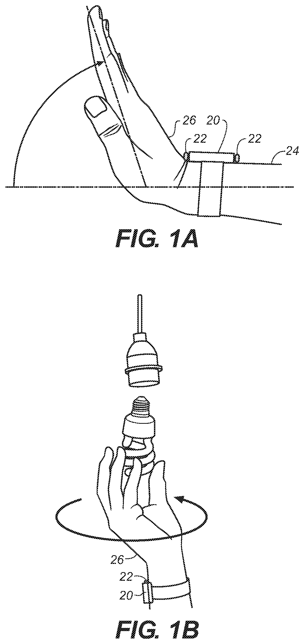
For instance, as shown in FIGS. 1A-1B, with a wearable electronic device 20 in the form of a watch, rotary input(s) may be in the form of a crown 22 that rotates to provide input to and control of the wearable electronic device 20. Since this crown 22 is a user input, external to the device, it is possible during normal wear that the crown 22 will be turned without the user intending it be turned--for example, when a user puts their hand in their pocket or rotates their wrist into extension (FIG. 1A), hitting the crown 22 into their lower forearm 24 or the back of their hand 26 (FIG. 1A). FIG. 1C shows an electronic device 20 positioned on a user's body (represented by dashed lines 24, 26) that could be the user's arm or back of the user's hand. If such a rotary input 22 also wakes the electronic device 20 from a sleep mode and turns on the screen, these false turns may not only be distracting to the user, they may also waste battery charge of device 20 that could have been saved for intended interactions.
Rotational motion of the user's hand or arm--such as shown in FIG. 1B or when for instance the user is opening a door, unscrewing a jar lid, or the like--may also result in inadvertent, unintentional false turns of the crown 22 of the wearable electronic device 20.
Accordingly, as recognized by the present inventors, what is needed are mechanisms and processes for detecting and rejecting false, unintended rotations of rotary inputs of electronic devices.
SUMMARY
According to one broad aspect of one embodiment of the present disclosure, disclosed herein is an electronic device configured to differentiate between false turns of a rotary input device unintended by a user, and valid turns of the rotary input device intended by the user. In one example, an electronic device may include a processor; a rotary input coupled with the processor, the rotary input having a shaft connected with a crown, the rotary input providing rotary input turn data to the processor when the rotary input is rotated; and a module operating on the electronic device, the module determining whether the rotary input turn data from the rotary input is invalid data resulting from unintended rotations of the rotary input.
In one example, the module determines whether an amount of rotations of the rotary input is greater than a threshold amount of rotations, and if not, the input turn data is considered invalid data. In another example, the module determines whether a rate of rotations of the rotary input is greater than a threshold rate of rotations, and if not, the input turn data is considered invalid data.
In another example, the electronic device may include a shield extending from the housing, the shield positioned around a bottom portion of the crown. The shield can reduce inadvertent contact between the user's body (such as the user's arm or back of the hand) with the crown of the rotary input.
In another example, the electronic device may include the shaft being positioned on the housing along an axis that is positioned above a centerline of the housing. In this manner, inadvertent contact between the user's body (such as the user's arm or back of the hand) with the crown of the rotary input is reduced when compared with an electronic device having the shaft of the rotary device positioned at or below the centerline of the housing.
In another example, the electronic device may include a light source positioned within the housing, the light source emitting light in a direction toward a portion of the user's body; and a detector positioned within the housing, the detector detecting one or more reflections of the light from the portion of the user's body. In this example, the module determines whether the portion of the user's body is in contact with the crown, and if so, the input turn data may be considered invalid data.
In another embodiment, the electronic device may include one or more capacitive sensors positioned on the crown, the sensors configured to detect contact with a user's finger. In this example, the module determines whether the rotation of the rotary input resulted from contact between the user's finger and the crown, and if not, the input turn data may be considered invalid data.
In another example, an electronic device may include one or more sensors detecting a position or movement/deflection of the shaft. In this example, based on the shaft deflection the module determines whether the rotation of the rotary input resulted from contact with an upper portion of the crown, and if not, the input turn data may be considered invalid data.
The electronic device may be in various forms, such as a wearable computing device having a touchscreen coupled with the processor. In one example, if the module determines that the input turn data is valid data from the rotary input, the processor alters the contents of the touch screen bases on the input turn data; and if the turn data is determined to be invalid data resulting from false, unintended turns of the rotary input, the turn data is rejected and the processor does not alter the contents of the touch screen based on the input turn data.
According to another broad aspect of another embodiment of the present disclosure, disclosed herein is an electronic device having a housing, wherein the electronic device may include a processor; at least one rotary input coupled with the processor, the rotary input providing rotary input turn data to the processor when the rotary input is rotated, the rotary input having a shaft connected with a crown; and at least one module operating on the electronic device, the module determining whether the rotary input turn data from the rotary input is valid data resulting from a user's rotations of the rotary input.
In one example, the module determines whether an amount of rotations of the rotary input is greater than a threshold amount of rotations, and if so, the input turn data may be considered valid data. In another example, the module determines whether a rate of rotations of the rotary input is greater than a threshold rate of rotations, and if so, the input turn data may be considered valid data.
In another example, the electronic device may include a light source positioned within the housing, the light source emitting light in a direction toward a portion of the user's body; and a detector positioned within the housing, the detector detecting one or more reflections of the light as reflected from the portion of the user's body; wherein the module determines whether the portion of the user's body is in contact with a lower portion of the crown, and if not, the input turn data may be considered valid data.
In another example, the electronic device may include one or more capacitive sensors positioned on the crown, the sensors configured to detect contact with a user's finger; wherein the module determines whether the rotation of the rotary input resulted from contact between the user's finger and the crown, and if so, the input turn data may be considered valid data.
In one example, the electronic device may include one or more sensors detecting a position of the shaft; wherein the module determines whether the rotation of the rotary input resulted from contact with an upper portion of the crown, and if so, the input turn data may be considered valid data.
According to another broad aspect of another embodiment of the present disclosure, disclosed herein is a process for an electronic device having at least one rotary input providing data, the process may include detecting one or more rotations of the rotary input; and determining whether the rotations resulted from inadvertent contact with the rotary input. In one example, if the determining operation determines that the rotations resulted from inadvertent contact with the rotary input, the data from the rotary input may be rejected.
In another example, the process may include detecting a distance between the electronic device and a portion of a user's body; and comparing the distance to a threshold distance to determine whether the rotations resulted from inadvertent contact with the rotary input.
In another example, the process may include detecting a presence or an absence of contact on the rotary input with a user's finger to determine whether the rotations resulted from inadvertent contact with the rotary input.
In one example, the process may include detecting a position of a shaft of the rotary input to determine whether the rotations resulted from inadvertent contact with the rotary input.
Other embodiments of the disclosure are described herein. The features, utilities and advantages of various embodiments of this disclosure will be apparent from the following more particular description of embodiments as illustrated in the accompanying drawings.
BRIEF DESCRIPTION OF THE DRAWINGS
FIG. 1A illustrates an example of a wearable electronic device positioned on a user's arm which can generate false, inadvertent turns of a crown of a rotary input.
FIG. 1B illustrates an example of a wearable electronic device positioned on a user's arm which can generate false, inadvertent turns of the crown of the rotary input.
FIG. 1C illustrates a representation of a wearable electronic device positioned on a user's arm which can generate false, inadvertent turns of the crown of the rotary input.
FIG. 2 illustrates an example of a wearable electronic device having one or more rotary inputs, in accordance with one embodiment of the present disclosure.
FIG. 3 illustrates an example of a block diagram of an electronic device having one or more rotatable inputs and one or more false turn rejection modules, in accordance with one embodiment of the present disclosure.
FIG. 4 illustrates an example of a block diagram of an electronic device with a rotary input, light source, and an optical detector to aid in detecting and rejecting false turns of the rotary input, in accordance with one embodiment of the present disclosure.
FIG. 5 illustrates an example of a process for detecting and rejecting false turns of a rotary input of an electronic device, in accordance with one embodiment of the present disclosure.
FIG. 6A illustrates an example of a block diagram of an electronic device with a rotary input having one or more capacitive sensors to aid in rejecting false turns of the rotary input, in accordance with one embodiment of the present disclosure.
FIG. 6B illustrates a side view of FIG. 6A showing an electronic device with a rotary input having one or more capacitive sensors to aid in rejecting false turns of the rotary input, in accordance with one embodiment of the present disclosure.
FIG. 7 illustrates an example of a process for detecting and rejecting false turns of a rotary input of an electronic device, in accordance with one embodiment of the present disclosure.
FIG. 8 illustrates an example of a block diagram of an electronic device with a rotary input and a shaft deflection detector to aid in rejecting false turns of the rotary input, in accordance with one embodiment of the present disclosure.
FIG. 9 illustrates an example of a process for detecting and rejecting false turns of a rotary input of an electronic device, in accordance with one embodiment of the present disclosure.
FIG. 10 illustrates an example of a block diagram of an electronic device with a rotary input and one or more modules to aid in detecting and rejecting false turns of the rotary input, in accordance with one embodiment of the present disclosure.
FIG. 11 illustrates an example of a process for detecting and rejecting false turns of a rotary input of an electronic device, in accordance with one embodiment of the present disclosure.
FIG. 12 illustrates an example of an electronic device with a rotary input having a mechanical structure to aid in reducing false turns of the rotary input, in accordance with one embodiment of the present disclosure.
FIG. 13 illustrates an example of an electronic device with a rotary input positioned at an offset position to aid in reducing false turns of the rotary input, in accordance with one embodiment of the present disclosure.
DETAILED DESCRIPTION
Disclosed herein are various embodiments of mechanisms and processes for detecting and rejecting false, unintended rotations of rotary inputs of electronic devices, such as wearable computing devices. In one example of the present disclosure, an electronic device is provided with an optical detector that measures the distance between the electronic device and a surface of the wearer's forearm or hand, and when the distance is smaller than a baseline or threshold distance, the turns of the rotary input may be considered to be false, unintended turns. In another example of the present disclosure, a crown of a rotary input of an electronic device includes one or more capacitive sensors which detect the presence of a wearer's finger, which when absent, the turns of the rotary input may be considered to be false, unintended turns. In another example, deflections or positions of a shaft of a rotary input of an electronic device are measured and if the deflections/positions indicate an upward force on the rotary input (which are likely caused by the wearer's forearm or hand), the turns of the rotary input may be considered to be false, unintended turns. Other embodiments are described herein.
FIG. 2 illustrates an example of a wearable electronic device 30 having a plurality of rotatable inputs 32, in accordance with one embodiment of the present disclosure. Electronic device 30, in this example in the form of a computing device wearable on a user's wrist, may have one or more rotary inputs 32 which may include a crown or other structure 34 which may be attached to a shaft 35, wherein the crown 34 is configured to be rotated by the user, for instance by one or more of the user's fingers or thumbs. The electronic device 30 may include a housing 36 that encloses and protects the contents of electronic device 30, a display 38 (such as a touch screen) to display data and information to the user as well as to accept touch input from the user, audio output/speakers 39, and in one example may also include a band or other structure 40 to attach the electronic device 30 to the user, for instance to the user's arm.
Device 30 may be configured to accommodate both left and right handed use, in which case a user can decide to orient the device 30 and crown 34 pointing either up the user's arm or down the user's arm, as desired.
Electronic device 30 may be configured as a portable computing device, and as shown in FIG. 3, may include a processor 42, memory 44 (which may include ROM and RAM for program memory and data stores), and communications interfaces 46 (such as but not limited to wireless interfaces, Bluetooth interfaces, USB interfaces, Wi-Fi interfaces, TCP/IP interfaces, network communications interfaces, or any conventional communication interfaces).
Electronic device 30 may include various input devices 48, such as but not limited to, touch inputs 50 (which may be part of or separate from touchscreen 38), audio/microphone input 52, data from accelerometer(s) 53, and rotary inputs 32 which can be provided to enable a user to manipulate or control electronic device 30, and other inputs such as buttons, switches, sliders or any other conventional input.
In one example, rotary inputs 32 provide rotary input turn data to the processor 42, and such turn data may include, but is not limited to, a number of turns, or increments of turns, of crown 34, a direction of turns (e.g., clockwise or counterclockwise rotation of crown 34), a rate of turns, a length of time of rotations of crown 34, and other data and parameters as described herein.
As used herein, the terms "turns" or "rotations" or the like (such as in the phrases "false turns" or "inadvertent turns") include any movements, fractional rotations, partial rotations, full rotations, revolutions or any degree or amount of rotary movement of rotary input 32/crown 34, and these terms are used interchangeably herein.
Rotary input 32 allow a user to perform a variety of functions, such as but not limited to scroll contents of displays, scroll menus, scroll selections or options, manipulate lists or data, advance or rewind audio or video, move pointers, or perform other various controls of electronic device 30 or the content of display 38.
In accordance with some embodiments of the present disclosure, electronic device 30 may include one or more module(s) 54 for detecting and/or handling false or inadvertent movements or turns of the rotary inputs 32. Module(s) 54 may include one or more of the features, functions or processes disclosed herein. Module(s) 54 may be implemented in various manners, such as but not limited to, as hardware devices, specialized integrated circuits, logic, computer program products, code modules operating on processor 42 or device 30, or in any combination thereof.
Various embodiments of electronic device 30 are described having one or more module(s) 54 that can determine whether turns of rotary input 32/crown 34 (along with the associated rotary input turn data) are (or possibly are) false inadvertent turns with invalid data that were unintended by the user, or whether turns of rotary input 32/crown 34 (along with the associated rotary input turn data) are (or possibly are) turns with valid data that were intended by the user.
FIG. 4 illustrates an example of an electronic device 30 with a rotary input 32, wherein the electronic device is configured with a light source 60 to emit light 62 onto the wearer's body (such as the user's arm 24 or back of the user's hand 26), and a detector 64 that detects reflections of light 62. The light 62 can be emitted prior to and/or during rotation of the rotary input 32. Based on the characteristics of the reflections, electronic device 30 determines whether to reject the rotations of rotary input 32 as false, inadvertent rotations or as valid rotations intended by the user. For instance, the light 62 can be used to determine the distance from the crown to the wearer's arm 24 or back of the wearer's hand 26, and the determined distance can be used as a factor in deciding whether rotations of the crown 34 should be rejected or accepted. In one example, if the detected light reflections indicate that the wearer's arm 24 or hand 26 are outside of a specified distance away from the crown 34, then the rotations of crown 34 can be deemed valid rotations intended by the user; and conversely, if the detected light reflections indicate that the wearer's arm 24 or hand 26 are within a specified distance near the crown 34, then the rotations of crown 34 can be deemed false, inadvertent rotations and rejected.
In another example, the distance from the crown to the user's arm 24 or hand 26 is used as a factor in deciding whether to accept or reject rotations of the crown 34. For example, when the distance from the crown to the user's arm 24 or hand 26 goes to zero or is within a defined distance, turns of the crown 34 would be rejected unless it is detected that the crown was touched in at least two discrete places, such as a top portion of the crown and a bottom portion of the crown, such as when the user is attempting to rotate the crown while the user's hand is in an extension position.
In one example, the light source 60 can be a light emitting diode (LED) such as an infrared LED. In one embodiment, the shaft 35 of the rotary input 32 (or portions of the shaft) may be clear or transparent or may include a light pipe, and the light source 60 may be configured so that the light emits out of the shaft 35. In another example, the light source 60 may be positioned to transmit light out of the housing 36 of the electronic device 30, such as through an opening or a window in the housing 36.
Detector 64 can be an optical detector such as a photodiode that detects reflected light, such as but not limited to infrared light. The housing 36 may be provided with a window, and the detector 64 can be placed within the housing 36 adjacent to the window. For instance, the window may be a dedicated window in the housing 36, or a speaker port or other opening in the housing 36 can also serve as the window where the detector receives reflected light.
In FIG. 5, an example of a process for detecting and rejecting false turns of a rotary input of an electronic device is shown, in accordance with one embodiment of the present disclosure. At operation 70 light is transmitted by the electronic device. In one example, operation 70 transmits infrared light, although other types of light may be transmitted. Operation 72 detects reflections of the transmitted light.
At operation 74, a distance can be calculated based on the transmitted light of operation 70 and reflected light detected by operation 72. For instance, operation 72 can detect reflections of the transmitted light off of a user's arm or back of the hand depending upon the position of the electronic device relative to the user.
In one example, operations 70-74 may be performed during an initialization or calibration phase, for instance by prompting the user through the display of the electronic device for the user to place the electronic device on the user's wrist in a normal, flat, non-extended position. This can be used to determine a baseline or default distance value.
At operation 76, movements or turns of the crown or rotary input are detected, and operation 78 determines a distance, for instance a distance from the electronic device to a wearer's arm or back of the hand that exists while the crown is being rotated. In one example, operation 78 may include transmitting light, detecting reflected light, and calculating a distance based on the reflected light, in a manner similar to operation 70, 72, 74.
Operation 80 determines whether the distance measured by operation 80 is acceptable or unacceptable. For instance, operation 80 may determine whether the distance measured by operation 78 is below a desired threshold, wherein the threshold may be established by the distance calculated at operation 74. For instance, in one example, a distance of zero or near zero may indicate that the crown is in direct contact with the wearer's back of the hand or forearm. If an acceptable distance is measured by operation 78, then control may be passed to operation 82 where the rotations of the crown/rotary input are accepted as true, intended user input. Conversely, if an unacceptable distance is measured by operation 78, then control may be passed to operation 84 where the rotations of the crown/rotary input may be rejected as false, unintended user input. In another example, operation 84 may indicate that the unacceptable distance be used as a factor in determining whether the turns of the rotary input of the electronic device may be false turns.
If operations 80-82 determine that the turns of the rotary input are true, intended turns, then operation 86 can process the movements of the rotary inputs as needed so that the electronic device responds appropriately to the user input received through the rotary input (such as but not limited to, changing the contents of the display, providing audible feedback, or otherwise processing the rotary input received from the user).
In another embodiment of the present disclosure and referring to FIG. 6A-6B, an electronic device 30 can be formed having a rotary input 32 having one or more capacitive sensors 90 to aid in detecting and rejecting false turns of rotary input 32. In one example, capacitive sensors 90 are shown in FIG. 6B (side view) as four sensors 90A, 90B, 90C and 90D, each positioned about a portion of the crown 34. It is understood that more or fewer sensors 90 could be used, and sensors 90 could be positioned on other portions of crown 34 or positioned in different orientations on crown 34.
In one example, sensors 90 can be used sense distance to the wearer, for instance distance from the crown to the wearer's wrist or back of the hand, or to sense or detect actual contact therebetween. In another example, sensors 90 can also be used to detect a user's finger placed on top of crown 34, or on a side of crown 34, to actuate the crown. Sensors 90 can also be used to distinguish whether rotation of crown 34 is resulting from detected contact with the top of the crown, which would tend to indicate that the rotation is intended by the user through a finger of the user; or whether rotation is resulting from detected contact with the bottom of the crown 34, which would tend to indicate contact with a wearer's arm or back of their hand which is a false, unintended rotation that may be rejected.
In one example, electronic device 30 utilizes a rotary encoder (e.g., an absolute position rotary encoder) as part of the rotary input 32, and may also include with capacitive sensors 90 in the crown 34. The rotary encoder may be configured, in one example, to have marked lines, detents or other indicia delineating a portion, fraction, increment or unit of movement when compared with a full rotation of the rotary input 32. In one example, the rotary encoder may have 50 marked lines across a full 360 degree rotation, which can be interpolated upwardly by the processor 42, false turn rejection module 54 or other element within device 30, such as by a factor of four (4.times.) to create 200 counts per revolution or rotation which equates to approximately 1.8 degrees of resolution. In this manner, processor 54 and/or false turn rejection module 54 can detect a fractional/partial amount or degree of rotatory movement of the rotary input 32/crown 34 which is less than a full rotation of the rotary input 32/crown 34. It is understood that the amount of resolution of detected rotatory movement of rotary input 32/crown 34 can be larger or smaller in other embodiments, depending upon the particular implementation, as is the interpolation of such detected movement.
Electronic device 30 can be configured to dynamically determine, at any given time, which sensors 90 on the crown 34 are towards the upper portion or top surface 92 (FIG. 6A) of electronic device 30, and which sensors 90 on the crown are towards the lower portion or bottom surface 94 (FIG. 6A) of the electronic device 30. In one example, electronic device 30 could be configured so that rotations of the crown 34 resulting from contact detected by sensors 90 towards the lower portion/bottom 94 of the electronic device 30 may be ignored or rejected as false turns, while rotations of the crown 34 resulting from contact detected by sensors 90 towards the upper portion 92 of electronic device 30 may be accepted as valid input intended by the user. In another example, the lower portion of crown sensors 90 could be dynamically desensitized, while the upper portion of the crown sensors 90 could be dynamically highly sensitized.
In another example of the present disclosure, sensors 90 on crown 34 can be used to distinguish the touch of a finger versus false turns resulting from a touch of a wrist or back of the user's hand. Sensors 90 on crown 34 may sense the presence of a user's finger by determining a local capacitance maximum value detected; in contrast, the capacitance profile generated by contact of a user's wrist with sensors 90 may appear more like a plane of capacitance and less like a local maximum. In this manner, sensors 90 on crown 34 can be used to distinguish the touch of a finger versus false turns resulting from a touch of a wrist or back of the user's hand.
FIG. 7 illustrates an example of a process for detecting and rejecting false turns of a rotary input of an electronic device, in accordance with one embodiment of the present disclosure. At operation 100, the position of the capacitive sensors relative to the electronic device are determined. In one example, the position of the sensors relative to the top (92 in FIG. 6A) and/or bottom (94 in FIG. 6A) of the device may be determined based on the rotary position of the crown or position of the shaft of the crown, for instance through the use of a rotary encoder.
At operation 102, movements or turns of the rotary input device are detected. At operation 104, the capacitive sensors on the rotary input device are read, for instance, to determine which of the capacitive sensors detect touch or contact from a user. At operation 106, a determination is made whether the contact is originating from capacitive sensors positioned towards the bottom (94 in FIG. 6A) of the device or towards the top (92 in FIG. 6A) of the device. If operation 106 determines that contact is originating from sensors positioned towards the bottom of the device, then operation 108 may reject the turns of the rotary input as false or unintended turns.
Conversely, if operation 106 determines that contact is originating from sensors positioned toward the top of the device, then operation 110 may accept the turns of the rotary input as true, intended turns by the user. Operation 112 may then process the rotations of the rotary input, and the electronic device may respond accordingly.
In one example, if sensors towards the top and towards the bottom of the device are simultaneously triggered, this input scenario could mean that the user is contacting the top of the crown with a finger while the bottom of the crown is being contacted by the user's arm or back of the hand. In one example, such scenario could be processed as true user input based on an assumption that the user is intentionally rotating the rotary input in a manner that is overcoming the contact from the user's arm or back of the hand.
FIG. 8 illustrates an example of a block diagram of an electronic device 30 with a rotary input 32 having a crown 34 attached to a shaft 35, wherein a shaft deflection detector 120 is provided to aid in detecting and rejecting false turns of the rotary input 32, in accordance with one embodiment of the present disclosure. In one example, the shaft 35 of the rotary input 32 is positioned or supported by pivot supports or suspension supports 122, which may include one or more O-rings.
Shaft deflection detector 120, in one example, measures or determines the position of the shaft 35 (such as an internal end of the shaft 35), such as by determining the distance and/or direction that shaft 35 moves or travels during a rotation of rotary input 32. The deflections of shaft 35 are used to determine whether the turns of crown 34 are resulting from downward force for instance from a user's finger or thumb (which would be associated with true, intended rotary input), or resulting from upward force for instance from inadvertent contact between the crown 34 and the user's arm 24 or back of the hand 26 (which would be associated with false, unintended rotary input).
In another embodiment, detector 120 senses the moment or torque caused by downward pressure of a finger on the crown 34, compared to the negative moment caused by upward pressure of the user's arm 24 or wrist 26 on the crown 34.
FIG. 9 illustrates an example of a process for detecting and rejecting false turns of a rotary input of an electronic device, in accordance with one embodiment of the present disclosure.
At operation 130, the position of the shaft of the rotary input relative to the electronic device is determined. In one example, the position of the shaft relative to the top and/or bottom of the device may be determined for instance through the use of a position sensor or torque sensor configured to monitor the shaft.
At operation 132, movements or turns of the rotary input device are detected. At operation 134, the deflection or direction of shaft movement is detected. At operation 136, a determination is made whether the rotation of the crown/rotary input is originating from generally upward contact with the crown, or originating from generally downward contact with the crown. If operation 136 determines that the rotation of the crown/rotary input is originating from generally upward contact with the crown--for instance from inadvertent contact between the crown 34 and the user's arm 24 or back of the hand 26 which would be associated with false, unintended rotary input--then operation 138 may reject the turns of the rotary input as false or unintended turns.
Conversely, if operation 136 determines that the rotation of the crown/rotary input is originating from generally downward contact with the crown--for instance from contact from a user's finger or thumb into the crown which would be associated with true, intended rotary input--then operation 140 may accept the turns of the rotary input as true, intended turns by the user. Operation 142 may then process the rotations of the rotary input, and the electronic device may respond accordingly.
FIG. 10 illustrates an example an electronic device 30 with a rotary input 32 and one or more modules (for instance, modules 54 in FIG. 3) that aid in detecting and rejecting false turns of the rotary input 32, in accordance with one embodiment of the present disclosure.
In one example, modules 54 perform one or more functions or operations described herein. Modules 54 may also differentiate between true, intended turns of rotary input 32 and false, unintended turns of rotary input 32 by analyzing characteristics of the rotations detected by electronic device 30 when rotary
References
-
sooperarticles.com/health-fitness-articles/children-health-articles/how-vesag-helps-kids-women-visitors-218542.html
-
mhealth.vesag.com/?m=201012
-
virtualpressoffice.com/eventsSubmenu.do?page=exhibitorPage&showId=1551&companyId=5394
-
amazon.com/iPhone-Universal-Remote-Control-Accessory/dp/tech-data/B0038Z4
-
vyasa-kaaranam-ketkadey.blogspot.com/2011/03/vesag-wrist-watch-for-dementia-care.html
-
-
24-7pressrelease.com/press-release/vyzin-unveiled-personal-emergency-response-system-pers-with-remote-health-monitoring-that-can-be-used-for-entire-family-219317.php
-
deskthority.net/keyboards-f2/optical-switch-keyboards-t1474.html
-
whatafuture.com/2014/02/28/google-smartwatch/#sthash.Yk35cDXK.dpbs
-
ip.com
-
medicineandtechnology.com/2010/08/2010-mhealth-summit-emerges-as-major.html
-
sensetekgroup.com/2010/11/29/wireless-health-monitoring-system
-
ezinearticles.com/?How-Vesag-Helps-People-Who-Want-to-Be-There?&id-5423873
-
itnewsafrica.com/2010/11/mobile-innovation-helps-dementia-andalzheimer%E2%80%99s-patients
D00000
D00001
D00002
D00003
D00004
D00005
D00006
D00007
D00008
D00009
D00010
D00011
D00012

D00013

D00014

XML
uspto.report is an independent third-party trademark research tool that is not affiliated, endorsed, or sponsored by the United States Patent and Trademark Office (USPTO) or any other governmental organization. The information provided by uspto.report is based on publicly available data at the time of writing and is intended for informational purposes only.
While we strive to provide accurate and up-to-date information, we do not guarantee the accuracy, completeness, reliability, or suitability of the information displayed on this site. The use of this site is at your own risk. Any reliance you place on such information is therefore strictly at your own risk.
All official trademark data, including owner information, should be verified by visiting the official USPTO website at www.uspto.gov. This site is not intended to replace professional legal advice and should not be used as a substitute for consulting with a legal professional who is knowledgeable about trademark law.