Method for manufacturing rack and hollow rack bar
Yamawaki , et al.
U.S. patent number 10,612,642 [Application Number 15/948,116] was granted by the patent office on 2020-04-07 for method for manufacturing rack and hollow rack bar. This patent grant is currently assigned to NETUREN CO., LTD.. The grantee listed for this patent is NETUREN CO., LTD.. Invention is credited to Kenichi Aoki, Ryosuke Suzuki, Takashi Yamawaki.


View All Diagrams
| United States Patent | 10,612,642 |
| Yamawaki , et al. | April 7, 2020 |
Method for manufacturing rack and hollow rack bar
Abstract
A method of fabricating a rack, the method includes: supporting a first rack bar having a first toothed part on a shaft of the first rack bar; supporting a second rack bar having a second toothed part on a shaft of the second rack bar such that an axial center line of the second rack bar coincides with an axial center line of the first rack bar; supporting a joint member between the first and second rack bars such that an axial center line of the joint member coincides with the axial center lines of the first and second rack bars; rotating the joint member about the axial center lines of the first and second rack bars relative to the first and second rack bars; and bringing an end of the first rack bar and an end of the second rack bar into friction pressure welding with the joint member.
| Inventors: | Yamawaki; Takashi (Tokyo, JP), Suzuki; Ryosuke (Tokyo, JP), Aoki; Kenichi (Tokyo, JP) | ||||||||||
|---|---|---|---|---|---|---|---|---|---|---|---|
| Applicant: |
|
||||||||||
| Assignee: | NETUREN CO., LTD. (Tokyo,
JP) |
||||||||||
| Family ID: | 51059512 | ||||||||||
| Appl. No.: | 15/948,116 | ||||||||||
| Filed: | April 9, 2018 |
Prior Publication Data
| Document Identifier | Publication Date | |
|---|---|---|
| US 20180223981 A1 | Aug 9, 2018 | |
Related U.S. Patent Documents
| Application Number | Filing Date | Patent Number | Issue Date | ||
|---|---|---|---|---|---|
| 14895123 | |||||
| PCT/JP2014/065024 | May 30, 2014 | ||||
Foreign Application Priority Data
| Jun 3, 2013 [JP] | 2013-117096 | |||
| Current U.S. Class: | 1/1 |
| Current CPC Class: | B23K 20/1205 (20130101); F16H 55/26 (20130101); B23K 37/0443 (20130101); B23K 20/12 (20130101); B23K 20/129 (20130101); B23K 2103/04 (20180801) |
| Current International Class: | B23K 20/12 (20060101); F16H 55/26 (20060101); B23K 37/04 (20060101) |
| Field of Search: | ;228/112.1-114.5,2.1-2.3 |
References Cited [Referenced By]
U.S. Patent Documents
| 3337108 | August 1967 | Taylor |
| 3377009 | April 1968 | Lipp |
| 3472996 | October 1969 | Braid |
| 3580459 | May 1971 | Gage |
| 3609854 | October 1971 | Hasui |
| 3717295 | February 1973 | Woodall |
| 3779446 | December 1973 | Lemelson |
| 3838807 | October 1974 | Nomura |
| 3897896 | August 1975 | Louw |
| 3954215 | May 1976 | Takagi |
| 4043497 | August 1977 | Jones |
| 4193722 | March 1980 | Bishop |
| 4605151 | August 1986 | Brown |
| 5858142 | January 1999 | Tully |
| 6706127 | March 2004 | Duggirala |
| 6925899 | August 2005 | Ozeki |
| 7168282 | January 2007 | McLean |
| 7654165 | February 2010 | Roeske |
| 7721617 | May 2010 | Fukumura |
| 7887069 | February 2011 | Bilmayer |
| 9139221 | September 2015 | Takai |
| 9199662 | December 2015 | Ueno |
| 9884388 | February 2018 | Sweeting |
| 2002/0026845 | March 2002 | Tsubouchi |
| 2002/0073793 | June 2002 | Tsubouchi et al. |
| 2003/0097894 | May 2003 | Ozeki |
| 2003/0213321 | November 2003 | Tsubouchi et al. |
| 2004/0182125 | September 2004 | McLean |
| 2004/0256439 | December 2004 | Pfeiler |
| 2005/0255927 | November 2005 | Michioka |
| 2005/0257992 | November 2005 | Shiino |
| 2006/0016238 | January 2006 | Shiokawa |
| 2006/0113358 | June 2006 | Crasser |
| 2006/0278466 | December 2006 | Cheng |
| 2007/0051776 | March 2007 | Estes |
| 2007/0057479 | March 2007 | Wolf |
| 2007/0137343 | June 2007 | Roeske |
| 2008/0127762 | June 2008 | Baxter |
| 2009/0200356 | August 2009 | Kawaura |
| 2009/0242613 | October 2009 | Kawaura |
| 2009/0260467 | October 2009 | Kobayashi |
| 2010/0038167 | February 2010 | Bilmayer et al. |
| 2010/0052280 | March 2010 | Bilmayer |
| 2010/0162843 | July 2010 | Kobayashi et al. |
| 2010/0206861 | August 2010 | Rudolph |
| 2012/0160595 | June 2012 | Fujitomi |
| 2012/0186085 | July 2012 | Kobayashi et al. |
| 2012/0258329 | October 2012 | Tanabe |
| 2014/0060956 | March 2014 | Takai |
| 2015/0136304 | May 2015 | Onose |
| 2016/0023300 | January 2016 | Kimura |
| 2016/0083823 | March 2016 | Horikami |
| 2018/0031104 | February 2018 | Yamawaki |
| 2018/0304422 | October 2018 | Nomura |
| 2018/0306303 | October 2018 | Inagaki |
| 2 082 818 | Jul 2009 | EP | |||
| 42-87 | Jan 1967 | JP | |||
| 47-41662 | Oct 1972 | JP | |||
| 62-168260 | Oct 1987 | JP | |||
| 2002-154442 | May 2002 | JP | |||
| 2002-178094 | Jun 2002 | JP | |||
| 2002-224856 | Aug 2002 | JP | |||
| 2004-523365 | Aug 2004 | JP | |||
| 3772110 | May 2006 | JP | |||
| 2008-137497 | Jun 2008 | JP | |||
| 2009-734 | Jan 2009 | JP | |||
| 2013-13904 | Jan 2013 | JP | |||
| 02/076653 | Oct 2002 | WO | |||
Other References
|
International Search Report dated Aug. 26, 2014 in International Application No. PCT/JP2014/065024. cited by applicant . Office Action dated Jan. 27, 2017 in Japanese Patent Application No. 2013-117096 (with English translation). cited by applicant. |
Primary Examiner: Stoner; Kiley S
Attorney, Agent or Firm: Wenderoth, Lind & Ponack, L.L.P.
Claims
The invention claimed is:
1. A method of fabricating a rack, the method comprising: supporting a first rack bar having a first toothed part on a shaft of the first rack bar; supporting a second rack bar having a second toothed part on a shaft of the second rack bar such that an axial center line of the second rack bar coincides with an axial center line of the first rack bar; supporting a joint member between the first and second rack bars such that an axial center line of the joint member coincides with the axial center lines of the first and second rack bars, the joint member including a cylindrical joint body and a pair of planar parts extending inwardly from circumferentially opposite sides of the joint member; rotating the joint member about the axial center lines of the first and second rack bars relative to the first and second rack bars; and simultaneously bringing an end of the first rack bar and an end of the second rack bar into friction pressure welding with the joint member.
2. The method according to claim 1, wherein a rotation of the joint member is performed by a jig for providing a rotating force and an engaging part provided for engagement with the jig so as to prevent a sliding motion of the joint member about the axial center line of the joint member.
3. The method according to claim 2, wherein: the engaging part has concave portions, and the planar parts are parts of the concave portions, respectively; and the friction pressure welding is performed such that the rotating force is transmitted to the joint member via the engaging part having the concave portions, by providing the rotation force to the jig.
4. The method according to claim 1, wherein the joint member is solid.
5. A method of fabricating a rack, the method comprising: supporting a first rack bar having a first toothed part on a shaft of the first rack bar; supporting a second rack bar having a second toothed part on a shaft of the second rack bar such that an axial center line of the second rack bar coincides with an axial center line of the first rack bar; supporting a joint member between the first and second rack bars such that an axial center line of the joint member coincides with the axial center lines of the first and second rack bars, the joint member including a cylindrical joint body and a through hole penetrating the cylindrical joint body in a direction perpendicular to the axial center line of the joint member; rotating the joint member about the axial center lines of the first and second rack bars relative to the first and second rack bars; and simultaneously bringing an end of the first rack bar and an end of the second rack bar into friction pressure welding with the joint member.
6. The method according to claim 5, wherein a rotation of the joint member is performed by a jig for providing a rotating force and an engaging part provided for engagement with the jig so as to prevent a sliding motion of the joint member about the axial center line of the joint member.
7. The method according to claim 6, wherein: the through hole is the engaging part; and the friction pressure welding is performed such that the rotating force is transmitted to the joint member via the engaging part being the through hole, by providing the rotation force to the jig.
8. The method according to claim 5, wherein the joint member is solid.
Description
CROSS-REFERENCE TO RELATED APPLICATION
This application is based on Japanese Patent Application No. 2013-117096 filed on Jun. 3, 2013, the entire content of which is incorporated herein by reference.
TECHNICAL FIELD
The present invention relates to a method of forming a rack to fabricate a rack bar used for a steering device for a vehicle and a rack bar having the rack, which method is adapted particularly to an electric power steering device, in which a steering wheel is steered by a slide motion of a rack shaft to be geared with a steering pinion connected to the steering side and at the same time, the output of a motor to be controlled by steering torque is transmitted to an auxiliary pinion which is spaced apart from the steering pinion and is geared with the rack shaft, thereby accessorily supporting the steering operation.
BACKGROUND ART
An electric power steering device has been known to include a double-type mechanism (referred hereinafter to as a `double-pinion type`) in which two rack and pinions are provided. In the meantime, it is general that the two racks provided at two sites have different rotational phases with respect to the central line of a shaft.
In the rack bar for use in such a double-pinion type, the two-part racks have been formed by the following method. Specifically, a solid rack bar made of a material, such as e.g. JIS S45C carbon steel, is tooth-cut at two sites by a broaching machine. The rotational phases are controlled by numerical control (NC).
In addition, in a case of a hollow rack bar, rotational phases of toothed parts are NC-controlled at the time when flat-crushing machining is carried out. Further, in a case of a frictional press joined rack bar, solid or hollow materials having toothed parts are jointed together by means of frictional press joining (see e.g. JP 3772110 B2).
SUMMARY OF INVENTION
The fabrication method for the rack bar for use in the double-pinion type however has problems as follows: That is, in the case of the solid rack bar, the toothed parts are provided on either axial side of the rack bar, so that machining such as gun drilling or the like cannot be carried out and the whole weight of the rack bar increases as well. In addition, in case of the hollow rack bar, while it is possible to make the rack bar lighter, the rotational phases of the toothed parts can be dislocated during post tooth-formation and annealing processes, even though a difference between the rotational phases of the toothed parts was previously determined at the time when the flat crushing machining was carried out. Further, in the case of the frictional press joined rack bar, two-way taking or drilling is required because of the positioning in a rotational direction. Furthermore, degradation in precision of a position, which occurs due to deviation of rotational direction or centering, is not appropriate to the electric power steering device.
Accordingly, an object of the present invention is to provide a method of forming a rack which is capable of precisely positioning two toothed parts at a specified degree of phase difference, and a hollow rack bar having the rack.
In order to accomplish the object, the present invention provides a method of fabricating a rack and a hollow rack bar having the rack.
In a method of fabricating a rack, the method includes: supporting a first rack bar having a first toothed part on a shaft of the first rack bar; supporting a second rack bar having a second toothed part on a shaft of the second rack bar such that an axial center line of the second rack bar coincides with an axial center line of the first rack bar; supporting a joint member between the first and second rack bars such that an axial center line of the joint member coincides with the axial center lines of the first and second rack bars; rotating the joint member about the axial center lines of the first and second rack bars relative to the first and second rack bars; and simultaneously bringing an end of the first rack bar and an end of the second rack bar into friction pressure welding with the joint member.
A hollow rack bar includes first and second rack bars and a joint member. The first rack bar has a first toothed part on a hollow shaft of the first rack bar. The second rack bar has a second toothed part on a hollow shaft of the second rack bar. An axial center line of the second rack bar coincides with an axial center line of the first rack bar. The joint member is disposed between the first and second rack bars such that an axial center line of the joint member coincides with the axial center lines of the first and second rack bars. One end surface of the joint member is engaged with the first rack bar and the other end surface of the joint member is engaged with the second rack bar.
According to the present invention, it is possible to position two toothed parts at a specified degree of phase difference in high precision (with respect to deviation/bending/inclination or the like of shaft center).
BRIEF DESCRIPTION OF DRAWINGS
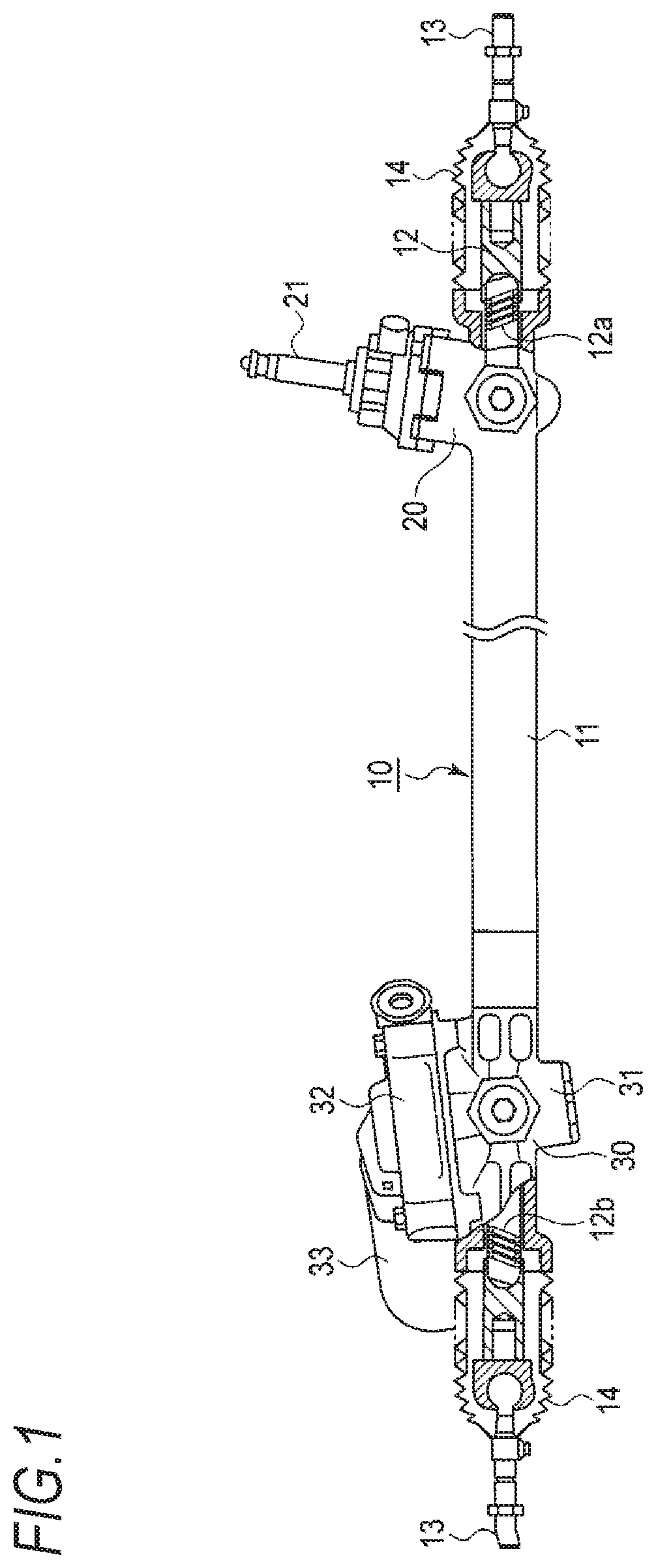
FIG. 1 is a view showing a rack and pinion mechanism having a double-pinion rack bar, which is fabricated by a method of fabricating a rack according to an embodiment of the present invention.
FIG. 2 is a plan view showing the double-pinion rack bar.
FIG. 3 is a perspective view showing a joint member provided in the double-pinion rack bar.
FIG. 4 is a view showing a procedure of manufacturing the double-pinion rack bar.
FIG. 5 is a view showing a procedure of manufacturing the double-pinion rack bar.
FIG. 6 is a view showing a procedure of manufacturing the double-pinion rack bar.
FIG. 7 is a view showing a procedure of manufacturing the double-pinion rack bar.
FIG. 8 is a view showing a procedure of manufacturing the double-pinion rack bar.
FIG. 9 is a view showing a procedure of manufacturing the double-pinion rack bar.
FIG. 10 is a view showing a procedure of manufacturing the double-pinion rack bar.
FIG. 11 is a view showing a procedure of manufacturing the double-pinion rack bar.
FIG. 12 is a plan view showing a double-pinion rack bar using a joint member according to a modified embodiment of the present invention.
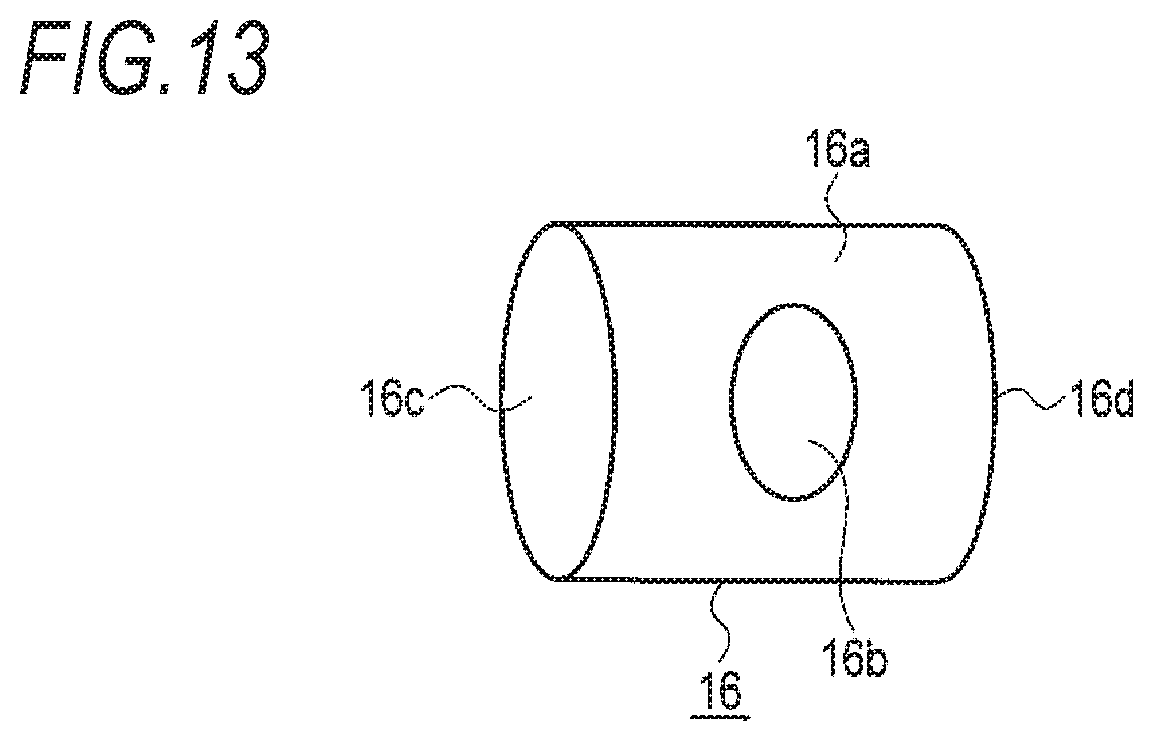
FIG. 13 is a perspective view showing the joint member.
FIG. 14 is a view showing a procedure of manufacturing the double-pinion rack bar with first and second rack bars having different outer diameters.
DESCRIPTION OF EMBODIMENTS
FIG. 1 is a view showing a rack and pinion mechanism having a double-pinion rack bar 12, which is fabricated by a method of fabricating a rack according to a first embodiment of the present invention, FIG. 2 is a plan view showing the double-pinion rack bar 12, FIG. 3 is a perspective view showing a joint member provided in the double-pinion rack bar 12, and FIGS. 4 to 11 are views showing a procedure of manufacturing the double-pinion rack bar 12.
The rack and pinion mechanism 10 includes a substantially cylindrical rack housing 11 which extends in a transverse direction of a vehicle, and the double-pinion rack bar 12 is accommodated in the rack housing 11 in such a way as to be slidably movable in a transverse axial direction of the rack housing.
The double pinion rack bar 12 extends outwards from opposite end-openings of the rack housing 11, and tie rods 13 and 13 are respectively coupled to both ends of the double pinion rack bar via respective joints, wherein the tie rods 13 and 13 extend laterally from boots 14 and 14 which respectively cover the joints. In operation, a motion of the double pinion rack bar 12 causes a motion of the tie rods 13 and 13, which in turn allows a steering wheel of a vehicle to be steered by a steering device.
A steering gear box 20 is provided at a right-side end of the rack housing 11. An input shaft 21, which is connected to a steering shaft, to which a steering wheel is integrally attached, via a joint, is supported by the steering gear box such that the input shaft is able to pivot by means of a bearing. The input shaft 21 is provided with a steering pinion (not shown).
The steering pinion is geared with a rack-toothed part (a first toothed part) 12a of the double pinion rack bar 12. The steering force transmitted to the input shaft 21 according to the turning manipulation of the steering wheel rotates the steering pinion having a diagonally toothed part engaged with the toothed part 12a, allowing the double pinion rack bar 12 to be slidably moved in a transverse axial direction.
An auxiliary gear box 30 is provided on a left-side end of the rack housing 11. The auxiliary gear box 30 includes a pinion cylinder part 31, which extends in a slightly tilted vertical direction with respect to the rack housing 11, and a rack guide cylinder part 32 extending perpendicular to the vertical direction.
An auxiliary pinion (not shown) is accommodated in the pinion cylinder part 31 such that the auxiliary pinion is geared with a rack-toothed part (a second toothed part) 12b of the double pinion rack bar 12. A motor 33 is attached to the auxiliary gear box 30, such that a driving shaft of the motor 33 rotates the auxiliary pinion having a diagonally toothed part meshed with the rack-toothed part 12b of the double pinion rack bar 12, allowing the double pinion rack bar 12 to be slidably moved in a transverse axial direction.
The motor 33 is controlled depending upon steering torque of the steering wheel detected through the input shaft 21. The steering action is performed in such a manner that an input steering force is transmitted to the double pinion rack bar 12 via the steering pinion, and the driving force of the motor 33 to be controlled by the steering torque is applied to the same double pinion rack bar 12 via the auxiliary pinion, thereby performing steering action while supporting the input.
FIG. 2 is a plan view showing the double rack bar 12. The double rack bar 12 has first and second toothed parts 12a and 12b, which respectively have angular positions (phases) with respect to an axis of the double pinion rack bar, which are different from each other by approximately 0 to 90 degrees.
In addition, the double pinion rack bar 12 consists of a first rack bar 12A which is formed with a hollow shaft and has the first toothed part 12a, a second rack bar 12B which is formed with a hollow shaft and has the second toothed part 12b, and a joint member 15, wherein the first and second rack bars and the joint member are coupled together with respective axial center lines aligned with each other.
The joint member 15 includes a cylindrical joint body 15a and opposite planar parts (engaging parts) 15b on opposite sides thereon. The planar parts 15b form so called two-way taking engaging parts. In FIG. 2, reference signs 15c and 15d respectively indicate one-side end and another-side end, which are provided for the connection with friction pressure welding surfaces Qa and Qb which will be described later. In addition, the joint body 15a may have a cylindrical shape.
The joint member 15 may be composed of the same material as the first and second rack bars 12A and 12B or other metal material which is suitable for friction pressure welding working. Specifically, S34C carbon steel or the like, which has been widely used as an industrial material, may be proper because the steel is cost-effective, is easily available, is easily cut-processed, and has a proper strength.
The double pinion rack par 12 having the above-mentioned construction is fabricated in the following manner. As shown in FIG. 4, first and second rack bars 12A and 12B on which the rack toothed parts 12a and 12b are respectively previously formed are prepared. In FIG. 4, reference signs Qa and Qb indicate friction pressure welding surfaces for a joint member 15. Here, before the friction pressure welding, the first and second toothed parts 12a and 12b of the first and second rack bars 12A and 12B, and the friction pressure welding surfaces Qa and Qb are cut to have the squareness, so that the straightness of the entire rack bar after friction pressure welding can be secured in high precision degree.
Next, as shown in FIG. 5, a joint member 15 is arranged between the first and second rack bars 12A and 12B with its axial center line aligned with those of the first and second rack bars 12A and 12B. Meanwhile, opposite-side surfaces 15c and 15d of the joint member 15 maintain high-leveled parallelization.
Next, as shown in FIG. 6, the first and second rack bars 12A and 12B are fixed such that the rack bars are not rotated about the axial center line.
Next, as shown in FIG. 7, the planar parts 15b of the joint member 15 are engaged with a jig 100. Then, as shown in FIG. 8, the jig 100 is rotated about the axial center line. Then, as shown in FIG. 9, the first rack bar 12A is axially pressed against one-side surface of the joint member 15 and at the same time, the second rack bar 12B are axially pressed against the other-side surface of the joint member 1. Reference sign P in FIG. 9 indicates a joint part.
Accordingly, friction heat is generated to cause a metal structure to change, and pressure is applied as well, so that the first rack bar 12A and the second rack bar 12B are respectively bonded to the joint member 15.
Further, as shown in FIG. 10, the rotation of the jig 100 is stopped. Here, a phase difference with respect to axial center line between the first and second rack bars 12A and 12B is set to a predetermined value. In the meantime, the degree of precision in determining a phase is about .+-.0.1.degree., which does not cause a problem in practical use
Next, as shown in FIG. 11, the first rack bar 12A and the second rack bar 12B are decoupled from each other, thereby forming a double pinion rack bar 12.
In the method of fabricating the double pinion rack bar, two rack bars can be fabricated in a conventional working manner. Further, since the two rack bars are simultaneously coupled at both surfaces in a friction pressure welding manner using the joint member 15, it is possible to secure peripheral position-precision, and coaxiality/straightness of the rack toothed parts 12a and 12b at two sites in high precision. Accordingly, a double pinion rack bar adaptable to an electric power steering device can be obtained.
In addition, since it is possible to use a hollow shaft member, in a case of 26 mm diameter member, the hollow shaft member can be reduced in weight by about 40% to 50% compared to a solid shaft member.
Meanwhile, the joint member 15 may be cut to have an outer diameter to suit an outer diameter of the first and second rack bars 12A and 12B.
FIG. 12 is a plan view showing a double pinion rack bar 12 using a joint member 16 modified from the above embodiment. FIG. 13 is a perspective view showing the joint member 16. In FIG. 12, the same functional parts as in FIGS. 1 and 2 are assigned as the same reference signs as in FIG. 3, and a detailed description thereof will be omitted.
The joint member 15 is formed into a cylindrical shape which is provided with a central through-hole (engaging hole) 16b. A jig 100 is engaged with the through-hole 16b. In addition, reference signs 16c and 16d in FIG. 13 indicate opposite-side ends for the engagement with the friction pressure welding surfaces Qa and Qb, respectively.
The case using the modified joint member 16 may also have the same effects as the case of fabricating the double pinion rack bar 12 using the above-mentioned joint member 15.
In the meantime, although the present embodiment illustrates that the rack bar having the hollow shaft and the rack bar having the hollow shaft are engaged together, it is possible to accomplish other combination such as a rack bar having a solid shaft and a rack bar having a solid shaft, or a rack bar having a hollow shaft and a rack bar having a solid shaft, which can be arranged opposite the combination of a rack bar having a hollow shaft and a rack bar having a solid shaft. Thus, hollow or solid shafts can be selected and bonded together depending upon a desired function, so the degree of freedom in designing the double pinion rack bar can be increased.
Further, since the rack bar disposed on either steering-side or assist-side side is subjected to a cold sequential forming suitable for forming a complex shaped toothed part such as VGR or the like while forming a toothed part having a shape in which a sufficient tooth width or tooth height is simply required, a shape such as CGR or the like may be set to have a combination of tooth shapes capable of implementing desired performance.
Furthermore, as shown in FIG. 14, the first and second rack bars 12A and 12B may have different outer diameters.
Of course, the present invention is not limited to the above-mentioned embodiment, but may be modified into a variety of forms without departing from the scope of the present invention.
* * * * *
D00000
D00001
D00002
D00003
D00004
D00005
D00006
D00007
D00008
D00009
D00010
D00011
XML
uspto.report is an independent third-party trademark research tool that is not affiliated, endorsed, or sponsored by the United States Patent and Trademark Office (USPTO) or any other governmental organization. The information provided by uspto.report is based on publicly available data at the time of writing and is intended for informational purposes only.
While we strive to provide accurate and up-to-date information, we do not guarantee the accuracy, completeness, reliability, or suitability of the information displayed on this site. The use of this site is at your own risk. Any reliance you place on such information is therefore strictly at your own risk.
All official trademark data, including owner information, should be verified by visiting the official USPTO website at www.uspto.gov. This site is not intended to replace professional legal advice and should not be used as a substitute for consulting with a legal professional who is knowledgeable about trademark law.