Systems and methods for pose development using retrieved position of a pallet or product load to be picked up
Wong , et al.
U.S. patent number 10,611,613 [Application Number 15/400,136] was granted by the patent office on 2020-04-07 for systems and methods for pose development using retrieved position of a pallet or product load to be picked up. This patent grant is currently assigned to Crown Equipment Corporation. The grantee listed for this patent is Crown Equipment Corporation. Invention is credited to Christopher W. Goode, Andrew Evan Graham, Lucas B. Waltz, Lisa Wong.


| United States Patent | 10,611,613 |
| Wong , et al. | April 7, 2020 |
Systems and methods for pose development using retrieved position of a pallet or product load to be picked up
Abstract
A method and apparatus for using unique landmarks to position industrial vehicles during start-up. In one embodiment, a method of using pre-positioned objects as landmarks to operate an industrial vehicle is provided. The method comprises identifying a start-up scenario from sensor data, wherein the start-up scenario comprises a unique marker start-up or a pre-positioned object start-up. in response to the identified start-up scenario, either a unique marker or pre-positioned object is identified within a physical environment, wherein the pre-positioned object or unique marker corresponds with a sub-area of the physical environment. The industrial vehicle pose is determined in response to the identity of the pre-positioned object or unique marker and the industrial vehicle is operated based on the determined industrial vehicle pose.
| Inventors: | Wong; Lisa (Totara Heights, NZ), Graham; Andrew Evan (Waitakere, NZ), Goode; Christopher W. (Auckland, NZ), Waltz; Lucas B. (Coldwater, NZ) | ||||||||||
|---|---|---|---|---|---|---|---|---|---|---|---|
| Applicant: |
|
||||||||||
| Assignee: | Crown Equipment Corporation
(New Bremen, OH) |
||||||||||
| Family ID: | 50148748 | ||||||||||
| Appl. No.: | 15/400,136 | ||||||||||
| Filed: | January 6, 2017 |
Prior Publication Data
| Document Identifier | Publication Date | |
|---|---|---|
| US 20170121158 A1 | May 4, 2017 | |
Related U.S. Patent Documents
| Application Number | Filing Date | Patent Number | Issue Date | ||
|---|---|---|---|---|---|
| 14254953 | Apr 17, 2014 | 9580285 | |||
| 14079842 | Dec 8, 2015 | 9206023 | |||
| 13672260 | Nov 8, 2012 | ||||
| PCT/US2012/052247 | Aug 24, 2012 | ||||
| 13219271 | Aug 26, 2011 | ||||
| Current U.S. Class: | 1/1 |
| Current CPC Class: | G01S 5/16 (20130101); G01S 17/875 (20130101); G05D 1/0274 (20130101); G01S 17/86 (20200101); G01C 21/206 (20130101); B66F 9/063 (20130101); G01S 17/08 (20130101); G07C 5/08 (20130101); G01S 5/08 (20130101); G06F 17/00 (20130101); G05D 1/0234 (20130101); G05D 2201/0216 (20130101) |
| Current International Class: | B66F 9/06 (20060101); G06F 17/00 (20190101); G05D 1/02 (20200101); G01C 21/20 (20060101); G05G 1/02 (20060101); G05G 1/00 (20060101); G01S 5/16 (20060101); G07C 5/08 (20060101); G01S 5/08 (20060101); G01S 17/02 (20200101); G01S 17/08 (20060101); G01S 17/875 (20200101) |
References Cited [Referenced By]
U.S. Patent Documents
| 4043418 | August 1977 | Blakeslee |
| 4071740 | January 1978 | Gogulski |
| 4483407 | November 1984 | Iwamoto et al. |
| 4530056 | July 1985 | MacKinnon et al. |
| 4674048 | June 1987 | Okumura et al. |
| 4746977 | May 1988 | White |
| 4750123 | June 1988 | Christian |
| 4782920 | November 1988 | Gaibler et al. |
| 4800977 | January 1989 | Boegli et al. |
| 4816998 | March 1989 | Ahlbom |
| 4847769 | July 1989 | Reeve et al. |
| 4855915 | August 1989 | Dallaire |
| 4858132 | August 1989 | Holmquist |
| 4875172 | October 1989 | Kanayama |
| 4944357 | July 1990 | Wible et al. |
| 4996468 | February 1991 | Field et al. |
| 5011358 | April 1991 | Andersen et al. |
| 5051906 | September 1991 | Evans et al. |
| 5170352 | December 1992 | McTamaney et al. |
| 5175480 | December 1992 | McKeefery et al. |
| 5202832 | April 1993 | Lisy |
| 5208753 | May 1993 | Acuff et al. |
| 5276618 | January 1994 | Everett |
| 5283739 | February 1994 | Summerville et al. |
| 5315517 | May 1994 | Kawase et al. |
| 5324948 | June 1994 | Dudar et al. |
| 5350033 | September 1994 | Kraft |
| 5367458 | November 1994 | Roberts |
| 5402344 | March 1995 | Reister et al. |
| 5446356 | August 1995 | Kim et al. |
| 5461292 | October 1995 | Zondlo |
| 5471393 | November 1995 | Bolger et al. |
| 5487009 | January 1996 | Hill et al. |
| 5488277 | January 1996 | Nishikawa et al. |
| 5491670 | February 1996 | Weber |
| 5515934 | May 1996 | Davis |
| 5535843 | July 1996 | Takeda et al. |
| 5539638 | July 1996 | Keeler et al. |
| 5545960 | August 1996 | Ishikawa |
| 5548511 | August 1996 | Bancroft |
| 5548512 | August 1996 | Quraishi |
| 5568030 | October 1996 | Nishikawa et al. |
| 5586620 | December 1996 | Dammeyer et al. |
| 5612883 | March 1997 | Shaffer et al. |
| 5646845 | July 1997 | Gudat et al. |
| 5652489 | July 1997 | Kawakami |
| 5680306 | October 1997 | Shin et al. |
| 5682317 | October 1997 | Keeler et al. |
| 5684696 | November 1997 | Rao et al. |
| 5687294 | November 1997 | Jeong |
| 5699444 | December 1997 | Palm |
| 5709007 | January 1998 | Chiang |
| 5739657 | April 1998 | Takayama et al. |
| 5764014 | June 1998 | Jakeway et al. |
| 5819008 | October 1998 | Asama et al. |
| 5819863 | October 1998 | Zollinger et al. |
| 5867800 | February 1999 | Leif |
| 5908466 | June 1999 | Veugen et al. |
| 5911767 | June 1999 | Garibotto et al. |
| 5916285 | June 1999 | Alofs et al. |
| 5938710 | August 1999 | Lanza et al. |
| 5941935 | August 1999 | Fernandez et al. |
| 5942869 | August 1999 | Katou et al. |
| 5961571 | October 1999 | Gorr |
| 6012003 | January 2000 | .ANG.strom |
| 6038501 | March 2000 | Kawakami et al. |
| 6041274 | March 2000 | Onishi et al. |
| 6046565 | April 2000 | Thorne |
| 6092010 | July 2000 | Alofs et al. |
| 6122572 | September 2000 | Yavnai et al. |
| 6208916 | March 2001 | Hori |
| 6246930 | June 2001 | Hori |
| 6269291 | July 2001 | Segeren |
| 6272405 | August 2001 | Kubota |
| 6285951 | September 2001 | Gaskins et al. |
| 6295503 | September 2001 | Inoue et al. |
| 6308118 | October 2001 | Holmquist |
| 6314341 | November 2001 | Kanayama |
| 6325749 | December 2001 | Inokuchi et al. |
| 6338013 | January 2002 | Ruffner |
| 6360165 | March 2002 | Chowdhary |
| 6370453 | April 2002 | Sommer |
| 6374155 | April 2002 | Wallach et al. |
| 6385515 | May 2002 | Dickson et al. |
| 6442476 | August 2002 | Poropat |
| 6445983 | September 2002 | Dickson et al. |
| 6446005 | September 2002 | Bingeman et al. |
| 6453223 | September 2002 | Kelly et al. |
| 6454036 | September 2002 | Airey et al. |
| 6459955 | October 2002 | Bartsch et al. |
| 6459966 | October 2002 | Nakano et al. |
| 6461355 | October 2002 | Svejkovsky et al. |
| 6470300 | October 2002 | Benzinger et al. |
| 6493614 | December 2002 | Jung |
| 6496755 | December 2002 | Wallach et al. |
| 6502017 | December 2002 | Ruffner |
| 6539294 | March 2003 | Kageyama |
| 6580246 | June 2003 | Jacobs |
| 6584375 | June 2003 | Bancroft et al. |
| 6629735 | October 2003 | Galy |
| 6636802 | October 2003 | Nakano et al. |
| 6641355 | November 2003 | McInerney et al. |
| 6667592 | December 2003 | Jacobs et al. |
| 6816085 | November 2004 | Haynes et al. |
| 6842692 | January 2005 | Fehr et al. |
| 6917839 | July 2005 | Bickford |
| 6922632 | July 2005 | Foxlin |
| 6934615 | August 2005 | Flann et al. |
| 6946565 | September 2005 | Fedouloff et al. |
| 6952488 | October 2005 | Kelly et al. |
| 7015831 | March 2006 | Karlsson et al. |
| 7076336 | July 2006 | Murray, IV et al. |
| 7100725 | September 2006 | Thorne |
| 7147147 | December 2006 | Enright et al. |
| 7148458 | December 2006 | Schell et al. |
| 7162056 | January 2007 | Burl et al. |
| 7162338 | January 2007 | Goncalves et al. |
| 7177737 | February 2007 | Karlsson et al. |
| 7246007 | July 2007 | Ferman |
| 7272467 | September 2007 | Goncalves et al. |
| 7295114 | November 2007 | Drzaic et al. |
| 7305287 | December 2007 | Park |
| 7343232 | March 2008 | Duggan et al. |
| 7386163 | June 2008 | Sabe et al. |
| 7451021 | November 2008 | Wilson |
| 7451030 | November 2008 | Eglington et al. |
| 7499769 | March 2009 | Walker et al. |
| 7539563 | May 2009 | Yang et al. |
| 7610123 | October 2009 | Han et al. |
| 7646336 | January 2010 | Tan et al. |
| 7650231 | January 2010 | Gadler |
| 7679532 | March 2010 | Karlsson et al. |
| 7688225 | March 2010 | Haynes et al. |
| 7689321 | March 2010 | Karlsson |
| 7720554 | May 2010 | DiBernardo et al. |
| 7734385 | June 2010 | Yang et al. |
| 7739006 | June 2010 | Gillula |
| 7844364 | November 2010 | McLurkin et al. |
| 7996097 | August 2011 | DiBernardo et al. |
| 8020657 | September 2011 | Allard et al. |
| 8050863 | November 2011 | Trepagnier et al. |
| 8103383 | January 2012 | Nakamura |
| 8126642 | February 2012 | Trepagnier et al. |
| 8150650 | April 2012 | Goncalves et al. |
| 8204679 | June 2012 | Nakamura |
| 8255107 | August 2012 | Yang et al. |
| 8271069 | September 2012 | Jascob et al. |
| 8280623 | October 2012 | Trepagnier et al. |
| 8296065 | October 2012 | Haynie et al. |
| 8538577 | September 2013 | Bell et al. |
| 2002/0049530 | April 2002 | Poropat |
| 2002/0095239 | July 2002 | Wallach et al. |
| 2002/0118111 | August 2002 | Brown et al. |
| 2002/0165638 | November 2002 | Bancroft et al. |
| 2002/0165790 | November 2002 | Bancroft et al. |
| 2003/0030398 | February 2003 | Jacobs et al. |
| 2003/0030399 | February 2003 | Jacobs |
| 2003/0212472 | November 2003 | McKee |
| 2003/0236590 | December 2003 | Park et al. |
| 2004/0002283 | January 2004 | Herbert et al. |
| 2004/0010337 | January 2004 | Mountz |
| 2004/0030493 | February 2004 | Pechatnikov et al. |
| 2004/0073337 | April 2004 | McKee et al. |
| 2004/0093116 | May 2004 | Mountz |
| 2004/0093650 | May 2004 | Martins et al. |
| 2004/0111184 | June 2004 | Chiappetta et al. |
| 2004/0195012 | October 2004 | Song et al. |
| 2004/0202351 | October 2004 | Park et al. |
| 2004/0249504 | December 2004 | Gutmann |
| 2005/0004702 | January 2005 | McDonald |
| 2005/0027443 | February 2005 | Cato |
| 2005/0029029 | February 2005 | Thorne |
| 2005/0075116 | April 2005 | Laird et al. |
| 2005/0080524 | April 2005 | Park |
| 2005/0131645 | June 2005 | Panopoulos |
| 2005/0140524 | June 2005 | Kato et al. |
| 2005/0149256 | July 2005 | Lawitzky et al. |
| 2005/0182518 | August 2005 | Karlsson |
| 2005/0216126 | September 2005 | Koselka et al. |
| 2005/0234679 | October 2005 | Karlsson |
| 2005/0244259 | November 2005 | Chilson et al. |
| 2005/0246078 | November 2005 | Vercammen |
| 2005/0246248 | November 2005 | Vesuna |
| 2006/0012493 | January 2006 | Karlsson et al. |
| 2006/0053057 | March 2006 | Michael |
| 2006/0055530 | March 2006 | Wang et al. |
| 2006/0061476 | March 2006 | Patil et al. |
| 2006/0095170 | May 2006 | Yang |
| 2006/0170565 | August 2006 | Husak et al. |
| 2006/0181391 | August 2006 | McNeill et al. |
| 2006/0184013 | August 2006 | Emanuel et al. |
| 2006/0218374 | September 2006 | Ebert |
| 2006/0267731 | November 2006 | Chen |
| 2006/0293810 | December 2006 | Nakamoto |
| 2007/0018811 | January 2007 | Gollu |
| 2007/0018820 | January 2007 | Chand et al. |
| 2007/0027612 | February 2007 | Barroot et al. |
| 2007/0050088 | March 2007 | Murray et al. |
| 2007/0061043 | March 2007 | Ermakov et al. |
| 2007/0090973 | April 2007 | Karlsson et al. |
| 2007/0106465 | May 2007 | Adam et al. |
| 2007/0118286 | May 2007 | Wang et al. |
| 2007/0150097 | June 2007 | Chae et al. |
| 2007/0153802 | July 2007 | Anke et al. |
| 2007/0213869 | September 2007 | Bandringa et al. |
| 2007/0244640 | October 2007 | Hirokawa |
| 2007/0262884 | November 2007 | Goncalves et al. |
| 2008/0015772 | January 2008 | Sanma et al. |
| 2008/0042839 | February 2008 | Grater |
| 2008/0046170 | February 2008 | DeGrazia |
| 2008/0167817 | July 2008 | Hessler et al. |
| 2008/0199298 | August 2008 | Chilson et al. |
| 2008/0272193 | November 2008 | Silverbrook et al. |
| 2009/0005986 | January 2009 | Soehren |
| 2009/0012667 | January 2009 | Matsumoto et al. |
| 2009/0140887 | June 2009 | Breed et al. |
| 2009/0198371 | August 2009 | Emanuel et al. |
| 2009/0210092 | August 2009 | Park et al. |
| 2009/0216438 | August 2009 | Shafer |
| 2009/0306946 | December 2009 | Badler et al. |
| 2010/0021272 | January 2010 | Ward et al. |
| 2010/0023257 | January 2010 | Machino |
| 2010/0161224 | June 2010 | Lee et al. |
| 2010/0204974 | August 2010 | Israelsen et al. |
| 2010/0222925 | September 2010 | Anezaki |
| 2010/0256908 | October 2010 | Shimshoni et al. |
| 2010/0268697 | October 2010 | Karlsson et al. |
| 2010/0286905 | November 2010 | Goncalves et al. |
| 2010/0286908 | November 2010 | Tate, Jr. et al. |
| 2010/0286909 | November 2010 | Tate, Jr. et al. |
| 2010/0312386 | December 2010 | Chrysanthakopoulos et al. |
| 2011/0010023 | January 2011 | Kunzig |
| 2011/0085426 | April 2011 | Kwon et al. |
| 2011/0121068 | May 2011 | Emanuel et al. |
| 2011/0125323 | May 2011 | Gutmann et al. |
| 2011/0148714 | June 2011 | Schantz et al. |
| 2011/0150348 | June 2011 | Anderson |
| 2011/0153338 | June 2011 | Anderson |
| 2011/0163160 | July 2011 | Zini et al. |
| 2011/0216185 | September 2011 | Laws et al. |
| 2011/0218670 | September 2011 | Bell et al. |
| 2011/0230207 | September 2011 | Hasegawa |
| 2012/0035797 | February 2012 | Oobayashi et al. |
| 2012/0101784 | April 2012 | Lindores et al. |
| 2012/0191272 | July 2012 | Andersen et al. |
| 2012/0239224 | September 2012 | McCabe et al. |
| 2012/0287280 | November 2012 | Essati et al. |
| 2012/0316784 | December 2012 | Chrysanthakopoulos |
| 2012/0323431 | December 2012 | Wong et al. |
| 2013/0006420 | January 2013 | Karlsson et al. |
| 2013/0101230 | April 2013 | Holeva et al. |
| 2013/0275045 | October 2013 | Tsujimoto et al. |
| 2014/0350831 | November 2014 | Hoffman et al. |
| 19757333 | Sep 1999 | DE | |||
| 10220936 | Dec 2003 | DE | |||
| 10234730 | Feb 2004 | DE | |||
| 102007021693 | Nov 2008 | DE | |||
| 508793 | Oct 1992 | EP | |||
| 1034984 | Sep 2000 | EP | |||
| 1201536 | May 2002 | EP | |||
| 1731982 | Dec 2006 | EP | |||
| 1732247 | Dec 2006 | EP | |||
| 1995206 | Nov 2008 | EP | |||
| 2385435 | Nov 2011 | EP | |||
| 2389947 | Dec 2003 | GB | |||
| 52066260 | Jun 1977 | JP | |||
| 60067818 | Apr 1985 | JP | |||
| 2002048579 | Feb 2002 | JP | |||
| 2002108446 | Apr 2002 | JP | |||
| 2005114546 | Apr 2005 | JP | |||
| 100814456 | Mar 2008 | KR | |||
| 2004015510 | Feb 2004 | WO | |||
| 2005068272 | Jul 2005 | WO | |||
| 2006128124 | Nov 2006 | WO | |||
| 2011044298 | Apr 2011 | WO | |||
| 2011085426 | Jul 2011 | WO | |||
| 2012166970 | Dec 2012 | WO | |||
Other References
|
Examination Report No. 1 dated Oct. 30, 2017 pertaining to Australian Divisional Patent Application No. 2016266099. cited by applicant . Azizi et al., "Mobile Robot Position Determination", Recent Advances in Mobile Robotics, Dr. Andon Topalov (Ed.), ISBN: 978-953-307-909-7, In Tech, Available from http://www.intechopen.com/books/recent-advances-in-mobile-robotics/mobile- -robot-position-determination, pp. 69-82, Dec. 2011. cited by applicant . Borenstein et al., "Mobile Robot Positioning-Sensors and Techniques", Journal of Robotic Systems, Special Issue on Mobile Robots, vol. 14, No. 4, pp. 231-249, Apr. 1997. cited by applicant . Feng et al., "Model-based calibration for sensor networks", Proceedings of IEEE, vol. 2, pp. 737-742, Pring IBSN: 0-7803-8133-5, Sensors, 2003. cited by applicant . Guizzo, "Three Engineer Hundreds of Robots One Warehouse", Spectrum IEEE, vol. 45, Issue 7, pp. 26-34, Jul. 2008. cited by applicant . Harmon et al., "A Technique for Coordinating Autonomous Robots", Autonomous Systems Branch Naval Ocean Systems Center San Diego, CA 92152, 1986. cited by applicant . Ibanez-Guzman et al., "Unmanned Tracked Ground Vehicle for Natural Environments", Nanyang Technological University, School of Computer Science, Singapore, 9 pages, 2004. cited by applicant . Jiesch, J. et al., "A Laser-Aided Inertial Navigation System (L-INS) for Human Localization in Unknown Indoor Environments", 2010 IEEE International Conference on Robotics and Automation, Anchorage, Alaska, pp. 5376-5382, May 3-8, 2010. cited by applicant . Jansfelt et al., "Laser Based Position Acquisition and Tracking in an Indoor Environment", Proc. Inst. Symp. Robotics and Automation, 1998. cited by applicant . Siadat et al., "An Optimized Segmentation Method for a 2D Laser-Scanner Applied to Mobile Robot Navigation", Proceedings of the 3rd IFAS Symposium on Intelligent Components and Instruments for Control Applications, 1997. cited by applicant . Thomson et al., Efficient Scheduling for Multiple Automated Non-Holonomic Vehicles using a Coordinated Path Planner:, IEEE International Conference on Rob otics and Automation (ICRA), pp. 1-4, May 9, 2011. cited by applicant . Xia et al., "Vision-Based Global Localization for Intelligent Vehicles", Resarch Institute of Robotics, Automation Department, Shanghao Jiao University, P.R. China, Intelligent Vehicles Symposium in Tokyo Japan, 6 pages, Jun. 13-15, 2006. cited by applicant . Yong, "Real-time Dynamic Path Planning for Dubins' Nonholonomic Robot", 45th IEEE Conference on Decision and Control, pp. 2418-2423, 2006. cited by applicant . Australian Examination Report pertaining to Application No. 2012300353 dated May 1, 2014. cited by applicant . Australian Examination Report pertaining to Application No. 2012259536 dated May 1, 2014. cited by applicant . Australian Examination Report pertaining to Application No. 2012243484 dated Jun. 4, 2014. cited by applicant . Australian Examination Report pertaining to Application No. 2011221652 dated Jun. 13, 2014. cited by applicant . Australian Examination Report pertaining to Application No. 2012304464 dated Jul. 23, 2014. cited by applicant . Australian Examination Report pertaining to Application No. 2015203030 dated Apr. 22, 2016. cited by applicant . Office Action pertaining to Chinese Patent Application No. 201280036678.4 dated Dec. 31, 2014. cited by applicant . Office Action pertaining to Chinese Patent Application No. 201280041527.8 dated Aug. 31, 2015. cited by applicant . Office Action pertaining to Chinese Application No. 201280041527.8 dated Aug. 31, 2015. cited by applicant . Extended European Search Report pertaining to Application No. 11750974.5 dated May 9, 2014. cited by applicant . European Search Report for Application No. 12770733.9 dated Sep. 1, 2014. cited by applicant . Extended European search report pertaining to European Patent Application No. 12789246.1 dated Nov. 18, 2014. cited by applicant . European Search Report pertaining to Application No. 14198585.3 dated May 2, 2016. cited by applicant . Communication pursuant to Rules 161(1) and 162 EPC pertaining to European Application No. 12773426.7 dated Apr. 17, 2014. cited by applicant . Communication pursuant to Rule 164(2)(b) and Article 94(3) EPC pertaining to European Application No. 12769782.9 dated Jun. 21, 2016. cited by applicant . Korean Preliminary Rejection pertaining to Application No. 10-2014-7000894 dated May 1, 2014. cited by applicant . Korean Preliminary Rejection pertaining to Application No. 10-2014-70000140 dated Aug. 29, 2014. cited by applicant . Final Rejection pertaining to U.S. Appl. No. 12/660,616 dated Nov. 27, 2012. cited by applicant . Office Action pertaining to U.S. Appl. No. 12/718,620 dated Mar. 5, 2010. cited by applicant . Office Action pertaining to U.S. Appl. No. 12/718,620 dated Nov. 8, 2012. cited by applicant . Office Action pertaining to U.S. Appl. No. 12/718,620 dated May 21, 2013. cited by applicant . Office Action pertaining to U.S. Appl. No. 12/948,358 dated Aug. 24, 2012. cited by applicant . Office Action pertaining to U.S. Appl. No. 12/948,358 dated Apr. 8, 2013. cited by applicant . Office Action pertaining to U.S. Appl. No. 13/116,600 dated Dec. 31, 2012. cited by applicant . Office Action pertaining to U.S. Appl. No. 13/153,743 dated Mar. 4, 2013. cited by applicant . Office Action pertaining to U.S. Appl. No. 13/159,500 dated Mar. 26, 2013. cited by applicant . Office Action pertaining to U.S. Appl. No. 13/159,501 dated Jun. 14, 2011. cited by applicant . Office Action pertaining to U.S. Appl. No. 13/159,501 dated Jan. 10, 2013. cited by applicant . Office Action pertaining to U.S. Appl. No. 13/159,501 dated Jun. 4, 2013. cited by applicant . Office Action pertaining to U.S. Appl. No. 13/166,600 dated Dec. 31, 2012. cited by applicant . Office Action pertaining to U.S. Appl. No. 13/219,271 dated Feb. 25, 2013. cited by applicant . Office Action pertaining to U.S. Appl. No. 13/227,165 dated Sep. 7, 2011. cited by applicant . Office Action pertaining to U.S. Appl. No. 13/227,165 dated Jul. 12, 2013. cited by applicant . Office Action pertaining to U.S. Appl. No. 13/300,041 dated Sep. 19, 2013. cited by applicant . Notice of Allowance pertaining to U.S. Appl. No. 13/300,041 dated Dec. 16, 2013. cited by applicant . Office Action pertaining to U.S. Appl. No. 13/672,260 dated Nov. 8, 2012. cited by applicant . Office Action pertaining to U.S. Appl. No. 13/672,260 dated May 8, 2013. cited by applicant . Office Action pertaining to U.S. Appl. No. 13/672,391 dated Jun. 4, 2014. cited by applicant . Examination Report dated Nov. 17, 2017 pertaining to European Patent Application No. 14198585.3. cited by applicant . Office Action pertaining to U.S. Appl. No. 14/079,842 dated May 8, 2015. cited by applicant . Office Action pertaining to U.S. Appl. No. 14/110,950, dated Sep. 30, 2014. cited by applicant . Office Action pertaining to U.S. Appl. No. 14/110,950 dated Mar. 4, 2015. cited by applicant . International Search Report and Written Opinion pertaining to Application No. PCT/NZ2011/000024 dated Dec. 7, 2011. cited by applicant . International Search Report and Written Opinion pertaining to Application No. PCT/NZ2012/000051 dated Jan. 2, 2013. cited by applicant . International Search Report and Written Opinion pertaining to Application No. PCT/NZ2012/000084 dated Jan. 30, 2013. cited by applicant . International Search Report and Written Opinion pertaining to Application No. PCT/NZ2012/000091 dated Oct. 31, 2012. cited by applicant . International Search Report and Written Opinion pertaining to Application No. PCT/US2012/052247 dated Nov. 27, 2012. cited by applicant . International Search Report and Written Opinion pertaining to Application No. PCT/US2012/054062 dated Nov. 27, 2012. cited by applicant . Written Opinion of the International Searching Authority pertaining to Application No. PCT/NZ2011/000025 dated Nov. 30, 2011. cited by applicant . Office Action dated Feb. 25, 2019 pertaining to Canadian Patent Application No. 2,989,895. cited by applicant. |
Primary Examiner: Mahne; Kevin P
Attorney, Agent or Firm: Dinsmore & Shohl LLP
Parent Case Text
CROSS-REFERENCE TO RELATED APPLICATIONS
This application is filed as a continuation of U.S. application Ser. No. 14/254,953 filed Apr. 17, 2014, which is a continuation of U.S. application Ser. No. 14/079,842 filed Nov. 14, 2013, which is a continuation of U.S. application Ser. No. 13/672,260 filed Nov. 8, 2012, which is a continuation of PCT/US2012/052247 filed on Aug. 24, 2012, which claims priority to U.S. patent application Ser. No. 13/219,271, filed Aug. 26, 2011.
Claims
What is claimed is:
1. A method of operating an industrial vehicle comprising an environmental sensor array mounted to the industrial vehicle, a lift carriage comprising one or more lifting elements, a landmark sensor mounted to the lift carriage, and a mobile computer, wherein the method comprises using the mobile computer in combination with the environmental sensor array, the landmark sensor, or a combination thereof, for: determining a current pose of the industrial vehicle in an environment based on measurement data from the environmental sensor array; navigating the industrial vehicle to a pallet or product load at a target destination utilizing the determined current pose of the industrial vehicle and data from the environmental sensor array; executing a load engagement operation such that the one or more lifting elements are positioned to pick-up the pallet or product load at the target destination, and such that the landmark sensor is positioned to sense unique feature information identifying the pallet or product load at the target destination; identifying unique pre-positioned object data associated with the pallet or product load at the target destination utilizing the landmark sensor when (i) the industrial vehicle is at the target destination, (ii) the load engagement operation is executed, and (iii) the unique feature information of the pallet or product load is sensed by the landmark sensor; developing a new pose of the industrial vehicle using the unique pre-positioned object data associated with the pallet or product load at the target destination; and navigating the industrial vehicle through the environment utilizing the new pose and data from the environmental sensor array of the industrial vehicle.
2. The method of claim 1, wherein the unique pre-positioned object data is associated with a unique identifier stored in a warehouse management system.
3. The method of claim 1, further comprising retrieving from a central computer a position of the pallet or product load associated with the unique pre-positioned object data.
4. The method of claim 3, wherein the position of the pallet or product load comprises an object identity and an object pose.
5. The method of claim 3, wherein the central computer is a warehouse management system.
6. The method of claim 1, wherein the mobile computer is mounted to the industrial vehicle.
7. The method of claim 1, wherein the industrial vehicle is an automated guided vehicle.
8. The method of claim 1, wherein the environment is segmented into a plurality of sub-areas.
9. The method of claim 1, wherein the environmental sensor array comprises a camera, a planar laser scanner, a laser range finder, a wheel encoder, or combinations thereof.
10. The method of claim 1, wherein the landmark sensor comprises a barcode scanner, an RFID scanner, or an image reader.
11. The method of claim 1, wherein: the environmental sensor array comprises a camera, a planar laser scanner, a laser range finder, a wheel encoder, or combinations thereof; and the landmark sensor comprises a barcode scanner, an RFID scanner, or an image reader.
12. The method of claim 1, wherein the load engagement operation is executed such that the pallet or product load at the target destination is picked up.
13. The method of claim 1, wherein the unique pre-positioned object data is stored locally on the industrial vehicle.
14. A system for operating an industrial vehicle, the system comprising a warehouse management system, the industrial vehicle, and one or more processors, wherein the industrial vehicle comprises an environmental sensor array mounted to the industrial vehicle, a lift carriage comprising one or more lifting elements, a landmark sensor mounted to the lift carriage, and a mobile computer in communication with the warehouse management system, and the one or more processors execute functions to use the mobile computer in combination with the environmental sensor array, the landmark sensor, or a combination thereof, to: determine a current pose of the industrial vehicle in an environment based on measurement data from the environmental sensor array; navigate the industrial vehicle to a pallet or product load at a target destination utilizing the determined current pose of the industrial vehicle and data from the environmental sensor array; execute a load engagement operation such that the one or more lifting elements are positioned to pick-up the pallet or product load at the target destination, and such that the landmark sensor is positioned to sense unique feature information identifying the pallet or product load at the target destination; identify unique pre-positioned object data associated with the pallet or product load at the target destination utilizing the landmark sensor when (i) the industrial vehicle is at the target destination, (ii) the load engagement operation is executed, and (iii) the unique feature information of the pallet or product load is sensed by the landmark sensor; develop a new pose of the industrial vehicle using the unique pre-positioned object data associated with the pallet or product load at the target destination; and navigate the industrial vehicle through the environment utilizing the new pose and data from the environmental sensor array of the industrial vehicle.
15. The system of claim 14, wherein the unique pre-positioned object data is associated with a unique identifier stored in the warehouse management system.
16. The system of claim 14, wherein the one or more processors further execute functions to retrieve from the warehouse management system a position of the pallet or product load associated with the unique pre-positioned object data.
17. The system of claim 14, wherein the mobile computer is mounted to the industrial vehicle.
18. The system of claim 14, wherein the environment is segmented into a plurality of sub-areas.
19. A system for operating an automated guided industrial vehicle, the system comprising a warehouse management system, the industrial vehicle, and one or more processors, wherein the industrial vehicle comprises an environmental sensor array mounted to the industrial vehicle, a lift carriage comprising one or more lifting elements, a landmark sensor mounted to the lift carriage, and a mobile computer mounted to the industrial vehicle and in communication with the warehouse management system, and the one or more processors execute functions to use the mobile computer in combination with the environmental sensor array, the landmark sensor, or a combination thereof, to: determine a current pose of the industrial vehicle in an environment based on measurement data; navigate the industrial vehicle to a pallet or product load at a target destination utilizing the determined current pose of the industrial vehicle and data from the environmental sensor array; execute a load engagement operation such that the one or more lifting elements are positioned to pick-up the pallet or product load at the target destination, and such that the landmark sensor is positioned to sense unique feature information identifying the pallet or product load at the target destination; identify unique pre-positioned object data associated with the pallet or product load at the target destination utilizing the landmark sensor when (i) the industrial vehicle is at the target destination, (ii) the load engagement operation is executed, and (iii) the unique feature information of the pallet or product load is sensed by the landmark sensor; develop a new pose of the industrial vehicle using the unique pre-positioned object data associated with the pallet or product load at the target destination; and navigate the industrial vehicle through the environment utilizing the new pose and data from the environmental sensor array of the industrial vehicle.
20. The system of claim 19, wherein the unique pre-positioned object data is associated with a unique identifier stored in the warehouse management system.
Description
BACKGROUND
Technical Field
Embodiments of the present invention generally relate to industrial vehicle navigation systems and, more particularly, to a method and apparatus for using unique landmarks to localize an industrial vehicle.
Description of the Related Art
Entities regularly operate numerous facilities in order to meet supply and/or demand goals. For example, small to large corporations, government organizations, and/or the like employ a variety of logistics management and inventory management paradigms to move objects (e.g., raw materials, goods, machines, and/or the like) into a variety of physical environments (e.g., warehouses, cold rooms, factories, plants, stores, and/or the like). A multinational company may build warehouses in one country to store raw materials for manufacture into goods, which are housed in a warehouse in another country for distribution into local retail markets. The warehouses must be well-organized in order to maintain and/or improve production and sales. If raw materials are not transported to the factory at an optimal rate, fewer goods are manufactured. As a result, revenue is not generated for the unmanufactured goods to counterbalance the costs of the raw materials.
Unfortunately, physical environments, such as warehouses, have several limitations that prevent timely completion of various tasks. Warehouses and other shared use spaces, for instance, must be safe for a human work force. Some employees operate heavy machinery and industrial vehicles, such as forklifts, which have the potential to cause severe or deadly injury. Nonetheless, human beings are required to use the industrial vehicles to complete tasks, which include object handling tasks, such as moving pallets of goods to different locations within a warehouse. Most warehouses employ a large number of forklift drivers and forklifts to move objects. In order to increase productivity, these warehouses simply add more forklifts and forklift drivers.
Some warehouses utilize equipment for automating these tasks. As an example, these warehouses may employ automated industrial vehicles, such as forklifts, to carry objects on paths and then, unload these objects onto designated locations. When navigating an industrial vehicle, it is imperative that vehicle pose computations are accurate. A vehicle pose in this context means its position and heading information, generally a pose refers to a position of an object in space with a coordinate frame having orthogonal axes with a known origin and the rotations about each of those axes or a subset of such positions and rotations. If the industrial vehicle cannot determine a current position on a map, the industrial vehicle is unable to execute tasks without prior knowledge of the physical environment. Furthermore, it is essential that the industrial vehicle perform accurate localization at start-up where there are few unique natural features, as inaccurate vehicle pose computations are detrimental to accurate vehicle navigation. Localization at start-up refers to any time a vehicle does not have a current pose such as after powering up or during operation when there is no currently valid pose.
Therefore, there is a need in the art for a method and apparatus for using unique markers for start-up localization of an industrial vehicle without prior knowledge of a position in the physical environment.
SUMMARY
Various embodiments of the present disclosure generally comprise a method and apparatus for using unique landmarks to position industrial vehicles during start-up. In one embodiment, a method of operating an industrial vehicle comprising one or more sensors, one or more lifting elements, and a mobile computer is provided. The method comprises using the industrial vehicle to receive measurement data from the one or more sensors of the industrial vehicle, determine a current pose of the industrial vehicle in an environment based on the measurement data, navigate the industrial vehicle to a pallet or product load utilizing the current pose and data from the one or more sensors of the industrial vehicle, position the lifting elements to pick-up the pallet or product load with the one or more lifting elements of the industrial vehicle, and develop a new pose of the industrial vehicle using the retrieved position of the pallet or product load retrieve a position of the pallet or product load from placed object data associated with the pallet or product load. The method can develop a new pose of the industrial vehicle using the retrieved position of the pallet or product load, and navigate the industrial vehicle through the environment utilizing the new pose and data from the one or more sensors of the industrial vehicle.
In another embodiment, a computer is coupled to an industrial vehicle and comprises an environment based navigation module for identifying a start-up scenario from sensor data and enabling operation of the vehicle based on a determined industrial vehicle pose. In a further embodiment, a computer-readable-storage medium is provided comprising one or more processor-executable instructions that, when executed by a processor, enables operation of the vehicle based on a determined industrial vehicle pose.
In another embodiment, a system for operating an industrial vehicle is provided. The system comprises a warehouse management system, the industrial vehicle, and one or more processors. The industrial vehicle comprises one or more sensors, one or more lifting elements, and a mobile computer in communication with the warehouse management system. The one or more processors can execute functions to receive measurement data from the one or more sensors of the industrial vehicle, determine a current pose of the industrial vehicle in an environment based on the measurement data, navigate the industrial vehicle to a pallet or product load utilizing the current pose and data from the one or more sensors of the industrial vehicle, position the lifting elements to pick-up the pallet or product load with the one or more lifting elements of the industrial vehicle, and retrieve a position of the pallet or product load from placed object data associated with the pallet or product load. The one or more processors can execute functions to develop a new pose of the industrial vehicle using the retrieved position of the pallet or product load, and navigate the industrial vehicle through the environment utilizing the new pose and data from the one or more sensors of the industrial vehicle.
BRIEF DESCRIPTION OF THE DRAWINGS
So that the manner in which the above recited features of the present invention can be understood in detail, a more particular description of the invention, briefly summarized above, may be had by reference to embodiments, some of which are illustrated in the appended drawings. It is to be noted, however, that the appended drawings illustrate only typical embodiments of this invention and are therefore not to be considered limiting of its scope, for the invention may admit to other equally effective embodiments.
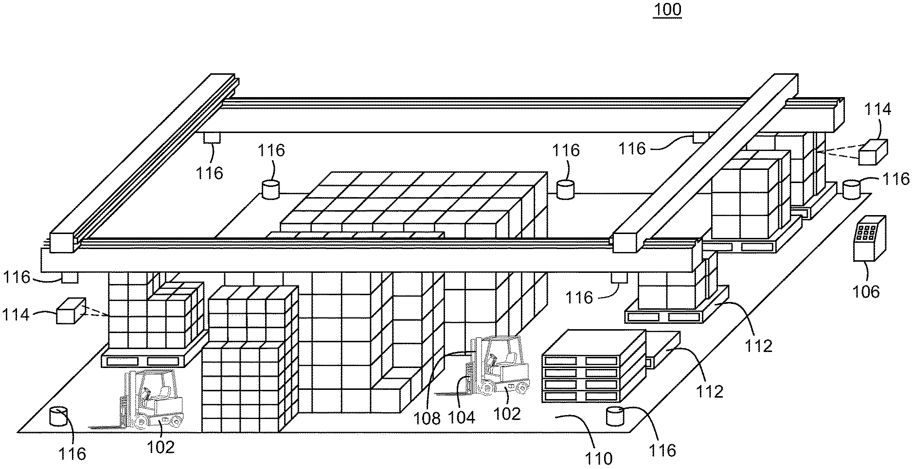
FIG. 1 is a perspective view of a physical environment comprising various embodiments of the present disclosure;
FIG. 2 illustrates a perspective view of the forklift for navigating a physical environment to perform various tasks according to one or more embodiments;
FIG. 3 is a structural block diagram of a system for using unique landmarks to position an industrial vehicle at start-up according to one or more embodiments;
FIG. 4 is a functional block diagram of a system for providing accurate localization for an industrial vehicle according to one or more embodiments;
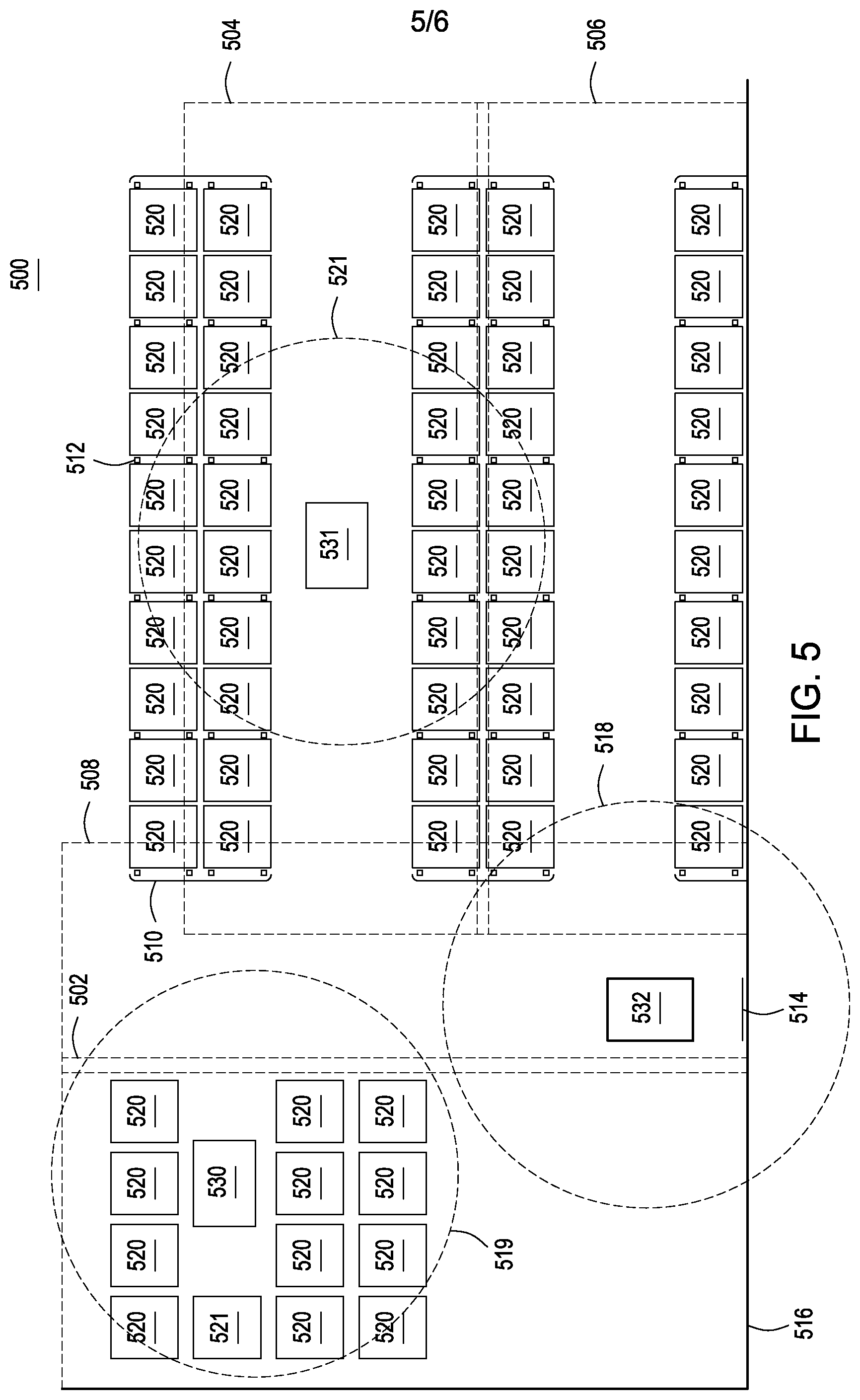
FIG. 5 is a schematic illustration of a map for a physical environment comprising unique landmarks according to one or more landmarks; and
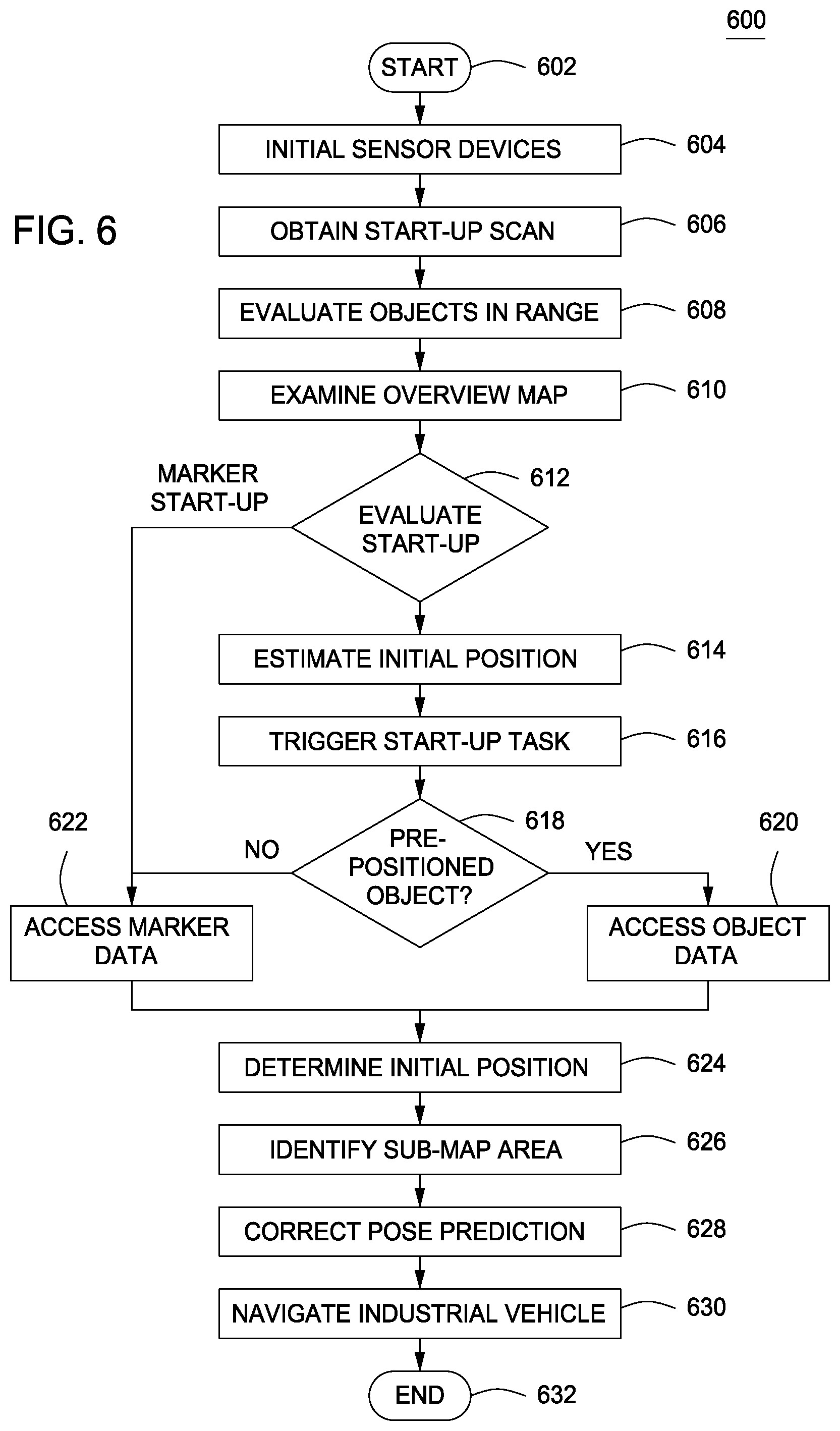
FIG. 6 is a flow diagram of a method of localizing an industrial vehicle with respect to an overview map at start-up.
DETAILED DESCRIPTION
FIG. 1 illustrates a schematic, perspective view of a physical environment 100 comprising one or more embodiments of the present invention.
In some embodiments, the physical environment 100 includes a vehicle 102 that is coupled to a mobile computer 104, a central computer 106 as well as a sensor array 108. The sensor array 108 includes a plurality of devices for analyzing various objects within the physical environment 100 and transmitting data (e.g., image data, video data, range map data, three-dimensional graph data and/or the like) to the mobile computer 104 and/or the central computer 106, as explained further below. The sensor array 108 includes various types of sensors, such as encoders, ultrasonic range finders, laser range finders, pressure transducers and/or the like.
The physical environment 100 further includes a floor 110 supporting a plurality of objects. The plurality of objects include a plurality of pallets 112, a plurality of units 114 and/or the like as explained further below. The physical environment 100 also includes various obstructions (not pictured) to the proper operation of the vehicle 102. Some of the plurality of objects may constitute as obstructions along various paths (e.g., pre-programmed or dynamically computed routes) if such objects disrupt task completion.
The physical environment 100 also includes a plurality of markers 116. The plurality of markers 116 are illustrated as objects attached to a ceiling. In some embodiments, the plurality of markers 116 are beacons, some of which are unique or provide a unique configuration, that facilitate environment based navigation as explained further below. The plurality of markers 116 as well as other objects around the physical environment 100 form environment features. The mobile computer 104 extracts the environment features and determines an accurate, current vehicle pose and the vehicle 102 is then operated based on the determined industrial vehicle pose.
The aforementioned vehicle operation may comprise one or more manual operations executed by a driver residing on the industrial vehicle, one or more automated operations executed with the assistance of a remote computer or a computer residing on the industrial vehicle, or combinations thereof. It is contemplated that the operations can be selected from a vehicle navigating operation, a vehicle positioning operation, a vehicle steering operation, a vehicle speed control operation, a load engagement operation, a lifting operation, a vehicle status alert display, or combinations thereof.
The physical environment 100 may include a warehouse or cold store for housing the plurality of units 114 in preparation for future transportation. Warehouses may include loading docks to load and unload the plurality of units from commercial vehicles, railways, airports and/or seaports. The plurality of units 114 generally include various goods, products and/or raw materials and/or the like. For example, the plurality of units 114 may be consumer goods that are placed on ISO standard pallets and loaded into pallet racks by forklifts to be distributed to retail stores. The industrial vehicle 102 facilitates such a distribution by moving the consumer goods to designated locations where commercial vehicles (e.g., trucks) load and subsequently deliver the consumer goods to one or more target destinations.
According to one or more embodiments, the vehicle 102 may be an automated guided vehicle (AGV), such as an automated forklift, which is configured to handle and/or move the plurality of units 114 about the floor 110. The vehicle 102 utilizes one or more lifting elements, such as forks, to lift one or more units 114 and then, transport these units 114 along a path to be placed at a designated location. Alternatively, the one or more units 114 may be arranged on a pallet 112 of which the vehicle 102 lifts and moves to the designated location.
Each of the plurality of pallets 112 is a flat transport structure that supports goods in a stable fashion while being lifted by the vehicle 102 and/or another jacking device (e.g., a pallet jack and/or a front loader). The pallet 112 is the structural foundation of an object load and permits handling and storage efficiencies. Various ones of the plurality of pallets 112 may be utilized within a rack system (not pictured). Within one type rack system, gravity rollers or tracks allow one or more units 114 on one or more pallets 112 to flow to the front. The one or more pallets 112 move forward until slowed or stopped by a retarding device, a physical stop or another pallet 112. In another type of rack, the pallets are placed on horizontal bars that interlock with the pallet structure. In this type of racking, the pallets on the lowest level are placed on the floor and protrude beyond the rack face, making it difficult to use the rack uprights as a navigational reference.
In some embodiments, the mobile computer 104 and the central computer 106 are computing devices that control the vehicle 102 and perform various tasks within physical environment 100. The mobile computer 104 is adapted to couple with vehicle 102 as illustrated. The mobile computer 104 may also receive and aggregate data (e.g., laser scanner data, image data, and/or any other related sensor data) that is transmitted by the sensor array 108. Various software modules within the mobile computer 104 control operation of the vehicle 102 as explained further below.
In many instances, some areas of the environment 100 are designated as block storage areas. In these areas, pallets 112 supporting a plurality of units 114 are stacked. Typically, these areas contain many rows of product, each of which is many pallets deep. Such stacked pallets are typically sufficiently high that beacons 116 or other items of fixed infrastructure are invisible to an industrial vehicle that is deep in a row of pallets.
In some embodiments, the mobile computer 104 is configured to determine a vehicle pose at start-up, which requires localization with respect to overview map without any knowledge of a previous vehicle pose. The overview map provides a-priori map data in a global coordinate system. Once the mobile computer 104 determines that a vehicle pose of the industrial vehicle 102 is unknown (e.g., when the automation system has just been started), the mobile computer 104 performs a search to determine the most likely position of the industrial vehicle 102 using various measurements extracted from sensor data, such as the geometry of the features (e.g. angles, lengths, radii). Based on the vehicle pose, the mobile computer 104 subsequently determines a path for completing a task within the physical environment 100.
In some embodiments, the mobile computer 104 uses a unique navigational beacon 116, such as a reflective barcode to determine an initial position. In other embodiments, the mobile computer recognizes a pre-placed pallet containing product and plans a path to the pre-placed product and navigates the industrial vehicle 102 such that the barcode on the product can be read. The mobile computer 104 then requests from the central computer 106 the location of the preplaced product and uses this location to determine an initial position for the vehicle. In further embodiments, the mobile computer 104 determines from various environment measurements that the industrial vehicle is located in a racking aisle and plans a path and drives the industrial vehicle to a location in the aisle, typically the end of the aisle, where sufficient unique landmarks can be measured to determine an initial position. It will be recognized by those skilled in the art that the industrial vehicle 102 requires an initial position in order to navigate successfully; however, embodiments of the invention described below use an initial position estimate to facilitate navigation when driving is required to determine a correct initial position.
As explained further below, the mobile computer 104 defines one or more sub-areas within the physical environment 100 for facilitating localization. It is appreciated, that the mobile computer 104 is not limited to performing start-up localization. Each of these sub-areas corresponds with a unique landmark, such as one of the plurality of markers 116 or one of the plurality of objects. Once the marker is recognized, the location of the sub-area associated with the marker will be used as start-up location estimate, once an initial position estimate is determined all sensor inputs are tested to ensure the sensor data is consistent with the estimated position and the position is refined to the final start-up position.
For example, and not by way of limitation, a unique landmark may include a placed item, such as one of the pallets 112 or one of the plurality of items 114 placed thereon, which can be uniquely identified (e.g. with a unique barcode, RFID, shape, or other attribute that is identifiable by the sensors of an industrial vehicle 102). In this case, when a pallet 112 and/or product load is scanned, picked-up, or otherwise engaged, the known location of such object, which can be stored, for example, in a warehouse management system database, can be used as a marker in a process for determining vehicle pose.
As another example, the plurality of markers 116 may include a plurality of beacons located at certain positions within the corresponding sub-areas arranged in a known and unique constellation. Alternatively, the unique landmark may include a reflective barcode, a visual glyph, an arrangement of light source elements that are configured to generate a unique light source signature, an arrangement of electrical, magnetic, or electromagnetic elements that are configured to generate a unique magnetic field signature, or unique painted or unpainted floor markings.
In one embodiment, the plurality of markers 116 comprise RF or other measurable wave signals that carry unique signatures and can be analyzed independently by corresponding sensor electronics on the vehicle to determine vehicle pose through triangulation.
As soon as the mobile computer 104 recognizes one of the unique landmarks, various software modules determine in which specific sub-area the industrial vehicle is located. If such a vehicle location is computed at start-up, the mobile computer 104 loads a corresponding sub-area map from a database as explained in detail further below. Alternatively, the mobile computer 104 only needs to request a specific sub-area map from the central computer 106 in order to navigate the industrial vehicle 102.
FIG. 2 illustrates a perspective view of the forklift 200 for facilitating automation of various tasks within a physical environment according to one or more embodiments of the present invention.
The forklift 200 (i.e., a lift truck, a high/low, a stacker-truck, trailer loader, sideloader, or a fork hoist) is a powered industrial truck having various load capacities and used to lift and transport various objects. In some embodiments, the forklift 200 is configured to move one or more pallets (e.g., the pallets 112 of FIG. 1) of units (e.g., the units 114 of FIG. 1) along paths within the physical environment (e.g., the physical environment 100 of FIG. 1). The paths may be pre-defined or dynamically computed as tasks are received. The forklift 200 may travel inside a storage bay that is multiple pallet positions deep to place or retrieve a pallet. Oftentimes, the forklift 200 is guided into the storage bay and places the pallet on cantilevered arms or rails. Hence, the dimensions of the forklift 200, including overall width and mast width, must be accurate when determining an orientation associated with an object and/or a target destination.
The forklift 200 typically includes two or more forks (i.e., skids or tines) for lifting and carrying units within the physical environment. Alternatively, instead of the two or more forks, the forklift 200 may include one or more metal poles (not pictured) in order to lift certain units (e.g., carpet rolls, metal coils, and/or the like). In one embodiment, the forklift 200 includes hydraulics-powered, telescopic forks that permit two or more pallets to be placed behind each other without an aisle between these pallets.
The forklift 200 may further include various mechanical, hydraulic, and/or electrically operated actuators according to one or more embodiments. In some embodiments, the forklift 200 includes one or more hydraulic actuators (not labeled) that permit lateral and/or rotational movement of two or more forks. In one embodiment, the forklift 200 includes a hydraulic actuator (not labeled) for moving the forks together and apart. In another embodiment, the forklift 200 includes a mechanical or hydraulic component for squeezing a unit (e.g., barrels, kegs, paper rolls, and/or the like) to be transported.
The forklift 200 may be coupled with the mobile computer 104, which includes software modules for operating the forklift 200 in accordance with one or more tasks. The forklift 200 is also coupled with an array comprising various sensor devices (e.g., the sensor array 108 of FIG. 1), which transmits sensor data (e.g., image data, video data, range map data, and/or three-dimensional graph data) to the mobile computer 104 for extracting information associated with environmental features. These devices may be mounted to the forklift 200 at any exterior and/or interior position or mounted at known locations around the physical environment 100. Exemplary embodiments of the sensors mounted on the forklift 200 typically include a camera 202, a planar laser scanner 204 attached to each side, and/or an encoder 206 attached to each wheel 208. In other embodiments, the forklift 200 includes only the planar laser scanner 204 and the encoder 206. In still further embodiments, the forklift 200 includes only the camera 202 and the encoder 206. The forklift 200 may use any sensor array with a field of view that extends to a current direction of motion (e.g., travel forwards, backwards, fork motion up/down, reach out/in, and/or the like). These encoders determine motion data related to vehicle movement. Externally mounted sensors may include laser scanners or cameras positioned where the rich data set available from such sensors would enhance automated operations. External sensors may include a limited set transponders and/or other active or passive means by which an automated vehicle could obtain an approximate position to seed a localization function. In some embodiments, a number of sensor devices (e.g., laser scanners, laser range finders, encoders, pressure transducers, and/or the like) as well as their position on the forklift 200 are vehicle dependent, and the position at which these sensors are mounted affects the processing of the measurement data. For example, by ensuring that all of the laser scanners are placed at a measurable position, the sensor array 108 may process the laser scan data and transpose it to a center point for the forklift 200. Furthermore, the sensor array 108 may combine multiple laser scans into a single virtual laser scan, which may be used by various software modules to control the forklift 200.
FIG. 3 is a structural block diagram of a system 300 for providing accurate start-up localization for an industrial vehicle according to one or more embodiments. In some embodiments, the system 300 includes the mobile computer 104, the central computer 106 and the sensor array 108 in which each component is coupled to each other through a network 302.
The mobile computer 104 is a type of computing device (e.g., a laptop, a desktop, a Personal Desk Assistant (PDA) and the like) that comprises a central processing unit (CPU) 304, various support circuits 306 and a memory 308. The CPU 304 may comprise one or more commercially available microprocessors or microcontrollers that facilitate data processing and storage. Various support circuits 306 facilitate operation of the CPU 304 and may include clock circuits, buses, power supplies, input/output circuits, and/or the like. The memory 308 includes a read only memory, random access memory, disk drive storage, optical storage, removable storage, and the like. The memory 308 includes various data, such as map data 310 the pose measurement data 316 pose prediction data 318, and initial pose prediction data 344. The map data includes: overview map data 350, sub-area maps 352, object feature information 312, landmark information 314, and placed (pre-positioned) object model data 342. The memory 308 includes various software packages, such as an environment based navigation module 320.
The central computer 106 is a type of computing device (e.g., a laptop computer, a desktop computer, a Personal Desk Assistant (PDA) and the like) that comprises a central processing unit (CPU) 322, various support circuits 324 and a memory 326. The CPU 322 may comprise one or more commercially available microprocessors or microcontrollers that facilitate data processing and storage. Various support circuits 324 facilitate operation of the CPU 322 and may include clock circuits, buses, power supplies, input/output circuits, and/or the like. The memory 326 includes a read only memory, random access memory, disk drive storage, optical storage, removable storage, and the like. The memory 326 includes various software packages, such as a map manager 328 and a task manager (not shown), as well as various data, such as a task 330.
The network 302 comprises a communication system that connects computing devices by wire, cable, fiber optic, and/or wireless links facilitated by various types of well-known network elements, such as hubs, switches, routers, and the like. The network 302 may employ various well-known protocols to communicate information amongst the network resources. For example, the network 302 may be part of the Internet or intranets using various communications infrastructure such as Ethernet, WiFi, WiMax, General Packet Radio Service (GPRS), and the like.
The sensor array 108 is communicably coupled to the mobile computer 104, which is attached to an automated vehicle, such as a forklift (e.g., the forklift 200 of FIG. 2). The sensor array 108 includes a plurality of devices 332 for monitoring a physical environment and capturing various data, which is stored by the mobile computer 104. In some embodiments, the sensor array 108 may include any combination of one or more laser scanners and/or one or more cameras. In some embodiments, the plurality of devices 332 may be mounted to the automated industrial vehicle. For example, a laser scanner and a camera may be attached to a lift carriage at a position above or, alternatively, below the forks.
In some embodiments, the map data 310 includes overview map data 350 which is used by the environment based navigation module 320 to evaluate the environment during start-up. The overview map data may include data identifying a variety of start-up scenarios, including the features to be observed in each scenario. For example, the overview map data may provide a generic aisle feature model, a generic blocked stack area feature model, feature models of environment walls and fixed infrastructure that may be unique, and unique navigational marker models such as a reflective beacon model. The environment based navigation module 320, when starting up, uses the overview map data to identify the start-up scenario as described further below.
In some embodiments, the map data 310 includes landmarks, which may be dynamic or static, from a physical environment, such as a shared use area for human workers and automated industrial vehicles. Each landmark is comprised of features which are sensor observable views of the associated landmarks. The map data 310 may include a vector of known observed and/or expected features. In some embodiments, the map data 310 indicates locations of objects (e.g., pre-positioned objects) throughout the physical environment. The physical environment may be segmented into a plurality of sub-areas with corresponding map data stored in the plurality of sub-area maps 352. Sub-area map generation is described in commonly assigned, U.S. patent application Ser. No. 13/159,501, filed Jun. 14, 2011, which is herein incorporated by reference in its entirety. The object feature information 312 defines features (e.g., curves, lines, and/or the like) associated with one or more infrastructure, obstacle, or pre-positioned objects. As described in further detail below, the environment based navigation module 320 may designate some of the one or more pre-positioned objects as unique landmarks that correspond to specific map sub-areas. The pre-positioned object is uniquely identifiable through the use of barcodes, RFID, specific shape, or any other unique feature that can be sensed by the sensors of an industrial vehicle. Once the object is identified, pre-positioned object data 342 may be accessed to inform the mobile computer 104 the details of the pre-positioned object, i.e., the pose of the object. If the object data for the identified object is not locally stored as data 342, the mobile computer can request the information from the central computer 106. The central computer 106 maintains placed object data 346 containing information regarding all pre-positioned objects. The pre-positioned object data 342 (i.e., pose of the pre-positioned object) is used by the mobile computer 104 to determine an accurate, initial vehicle pose.
After a pre-positioned object is used to compute an initial vehicle pose, the vehicle is capable of operating autonomously. In some embodiments, the map data 310 indicates locations for at least one landmark as defined in the landmark information 314. The landmark information 314 identifies a number of features that form each of the at least one landmark as well as other data, such as a landmark type, a location, measurement data, and/or the like. Some of the at least one landmarks are proximate to the industrial vehicle. For example, these proximate landmarks and the industrial vehicle may be co-located within a certain sub-area of the physical environment. By comparing feature information associated with the proximate landmarks with feature information associated with the unique landmarks, the environment based navigation module 320 determines an accurate vehicle pose.
In some embodiments, the pose measurement data 316 includes an aggregation of data transmitted by the plurality of devices 332. Such data indicates one or more observed features. In one embodiment, the one or more cameras transmit image data and/or video data of the physical environment that are relative to a vehicle. In another embodiment, the one or more laser scanners (e.g., three-dimensional laser scanners) analyze objects within the physical environment and capture data relating to various physical attributes, such as size and shape. The captured data can then be compared with three-dimensional object models. The laser scanner creates a point cloud of geometric samples on the surface of the subject. These points can then be used to extrapolate the shape of the subject (i.e., reconstruction). The laser scanners have a cone-shaped field of view. While the cameras record color information associated with object surfaces within each and every field of views, the laser scanners record distance information about these object surfaces.
The data produced by the laser scanner indicates a distance to each point on each object surface. Based on these distances, the environment based navigation module 320 determines a three-dimensional position of the each point in a local coordinate system relative to each laser scanner. The environment based navigation module 320 transposes each three-dimensional position to be relative to the vehicle. The laser scanners perform multiple scans from different perspectives in order to determine the points on the each and every object surface. The environment navigation module 320 normalizes the data produced by the multiple scans by aligning the distances along a common reference system, such as a global coordinate system. Then, these software modules merge the object features to create a model of the objects within a partial field of view.
In some embodiments, the pose prediction data 318 includes an estimate of vehicle position and/or orientation of which the present disclosure may refer to as the vehicle pose prediction. Initial pose prediction data 344 is available from the pre-positioned object data 342. Once a mobile computer 104 utilizes the initial pose prediction data 344, the environment based navigation module 320 produces updated estimates using a prior vehicle pose in addition to the sensor measurements to indicate an amount of movement (e.g. inertial measurement unit (IMU) or odometer). The environment based navigation module 320 may also use a process filter to estimate uncertainty and/or noise for an upcoming vehicle pose prediction and update steps. Using odometry data, for example, the environment based navigation module 320 computes the distance traveled by the industrial vehicle from a prior vehicle position, along with uncertainty of the pose given by the noise model of the odometry device. After subsequently referencing a map of the physical environment, and comparing other sensory data (e.g. laser range sensor, camera) with the map, the environment based navigation module 320 determines a more accurate estimate of a current vehicle position and update the pose uncertainty.
The environment based navigation module 320 includes processor-executable instructions for localizing the industrial vehicle 102 using unique landmarks according to some embodiments. In some embodiments, the environment based navigation module 320 designates a unique landmark (e.g., one of the plurality of items 114 or the plurality of markers 116 of FIG. 1) corresponding with a specific portion or sub-area of the physical environment. The environment based navigation module 320 may estimate an initial vehicle pose using a pre-positioned object (e.g., a placed product item or a pallet) or a placed landmark (e.g., a marker, such as a reflective navigation beacon). Using the object feature information 312, the environment based navigation module 320 updates the map data 310 to include the pre-positioned object or an empty slot that constitutes a lack of the pre-positioned object.
FIG. 4 is a functional block diagram of a system 400 for providing accurate localization for an industrial vehicle according to one or more embodiments. The system 400 includes the mobile computer 104, which couples to an industrial vehicle, such as a forklift, as well as the sensor array 108. Various software modules within the mobile computer 104 collectively form an environment based navigation module (e.g., the environment based navigation module 320 of FIG. 3).
The mobile computer 104 includes various software modules (i.e., components) for performing navigational functions, such as a localization module 402, a mapping module 404, a correction module 408, and a vehicle controller 410. The mobile computer 104 provides accurate localization for the industrial vehicle and updates map data 406 with current pose measurements. The localization module 402 also includes various components, such as a filter 414 and a feature extraction module 416. The map module 404 includes various data, such as a vehicle pose 418 and dynamic features 422. The map module 404 also includes various components, such as a feature selection module 420.
In some embodiments, the localization module 402 processes corrected sensor data from the correction module and modifies observed pose measurements therein. After comparing these pose measurements with a pose prediction, the filter 414 updates the pose prediction to account for an incorrect estimation and/or observation uncertainty. The filter 414 determines the vehicle pose 418 and communicates the pose to the mapping module 404. The vehicle pose 418, which is modeled by the filter 414, includes data (e.g., coordinates) indicating vehicle position and/or orientation. The localization module 402 communicates data associated with the vehicle pose 418 to the mapping module 404 while also communicating such data to the vehicle controller 410. Based on the vehicle position and orientation, the vehicle controller 410 navigates the industrial vehicle to a destination.
In addition to the filter 414 for calculating the vehicle pose 418, the localization module 414 also includes the feature extraction module 416 for extracting known standard features from the corrected sensor data. The feature selection module 420 compares the vehicle pose 418 with the map data to select a sub-area map (the sub-area map 352 of FIG. 3) proximate to the vehicle. The feature selection module further selects from available dynamic features 422 and static features 424 to provide the localization module 402 with a reduced number of features to examine by eliminating potentially invisible features from the feature set 422/424. The feature selection module 420 manages addition and modification of the dynamic features 422 to the map data 406. The feature selection module 420 can update the map data 406 to indicate areas recently occupied or cleared of certain features, such as known placed (pre-positioned) and picked objects.
It is appreciated that the system 400 may employ several computing devices to perform environment based navigation. Any of the software modules within the computing device 104 may be deployed on different or multiple physical hardware components, such as other computing devices. The mapping module 404, for instance, may be executed on a server computer (e.g., the central computer 106 of FIG. 1) over a network (e.g., the network 302 of FIG. 4) to connect with multiple mobile computing devices for the purpose of sharing and updating the map data 406 with a current vehicle position and orientation.
In some embodiments, the correction module 402 processes sensor input messages from disparate data sources, such as the sensor array 108, having different sample/publish rates for the vehicle pose 418 as well as different (internal) system delays. The correction module 402 extracts observed pose measurements from the sensor data within these messages. The correction module 402 examines each message separately in order to preserve the consistency of each observation. Such an examination may be performed in place of fusing the sensor data to avoid any dead reckoning errors. Notice that with different sampling periods and different system delays, the order at which the sensor data is acquired is not the same as the order at which the sensor input messages eventually became available to the computing device 104.
FIG. 5 is a schematic illustration of a map 500 for a physical environment comprising pre-positioned objects and unique landmarks according to one or more embodiments of the invention. The map 500 is partitioned into a sub-area 502, a sub-area 504, a sub-area 506, and a sub-area 508, where each sub-area presents a different start-up problem which is solved as further described below. The map 500 depicts three industrial vehicles 530/531/532 (e.g. the industrial vehicle 102 of FIG. 1) to be located in sub-areas 502/504 and 508. At start-up, the industrial vehicle 530/531/532 has no information about its pose, or which sub-area the vehicle is currently located. Sensors (e.g., laser scanners) coupled to the industrial vehicle 102 process measurement data within a range 518. The environment (e.g., the physical environment 100 of FIG. 1) also contains fixed landmarks such as walls 516, rack protectors 510, racking legs 512, and a placed unique navigational marker 514. The environment also includes a plurality of pre-positioned objects 520 and 521 for which the environment based navigation module e.g. the environment based navigation module 320 of FIG. 3) can obtain position data from the map manager (e.g., the map manager 340 of FIG. 3).
In one embodiment, during start-up, the industrial
References
D00000
D00001
D00002
D00003
D00004
D00005
D00006
XML
uspto.report is an independent third-party trademark research tool that is not affiliated, endorsed, or sponsored by the United States Patent and Trademark Office (USPTO) or any other governmental organization. The information provided by uspto.report is based on publicly available data at the time of writing and is intended for informational purposes only.
While we strive to provide accurate and up-to-date information, we do not guarantee the accuracy, completeness, reliability, or suitability of the information displayed on this site. The use of this site is at your own risk. Any reliance you place on such information is therefore strictly at your own risk.
All official trademark data, including owner information, should be verified by visiting the official USPTO website at www.uspto.gov. This site is not intended to replace professional legal advice and should not be used as a substitute for consulting with a legal professional who is knowledgeable about trademark law.