Twelve-cornered strengthening member
Tyan , et al.
U.S. patent number 10,611,409 [Application Number 15/838,148] was granted by the patent office on 2020-04-07 for twelve-cornered strengthening member. This patent grant is currently assigned to Ford Global Technologies, LLC. The grantee listed for this patent is Ford Global Technologies, LLC. Invention is credited to Yu-Kan Hu, Leonard Anthony Shaner, Tau Tyan.


| United States Patent | 10,611,409 |
| Tyan , et al. | April 7, 2020 |
Twelve-cornered strengthening member
Abstract
A strengthening member for an automotive vehicle includes a twelve-cornered cross section including sides and corners creating eight internal angles and four external angles. The strengthening member also includes four indentations extending along a length of the strengthening member. Each indentation is respectively defined by two of the eight internal angles and one if the four external angles of the strengthening member.
| Inventors: | Tyan; Tau (Northville, MI), Shaner; Leonard Anthony (New Baltimore, MI), Hu; Yu-Kan (Ypsilanti, MI) | ||||||||||
|---|---|---|---|---|---|---|---|---|---|---|---|
| Applicant: |
|
||||||||||
| Assignee: | Ford Global Technologies, LLC
(Dearborn, MI) |
||||||||||
| Family ID: | 42036885 | ||||||||||
| Appl. No.: | 15/838,148 | ||||||||||
| Filed: | December 11, 2017 |
Prior Publication Data
| Document Identifier | Publication Date | |
|---|---|---|
| US 20180099696 A1 | Apr 12, 2018 | |
Related U.S. Patent Documents
| Application Number | Filing Date | Patent Number | Issue Date | ||
|---|---|---|---|---|---|
| 14930299 | Nov 2, 2015 | 9840281 | |||
| 14010115 | Nov 3, 2015 | 9174678 | |||
| 12233808 | Sep 24, 2013 | 8539737 | |||
| Current U.S. Class: | 1/1 |
| Current CPC Class: | B60R 19/34 (20130101); B62D 29/007 (20130101); B62D 21/15 (20130101); B62D 21/152 (20130101); B62D 25/082 (20130101); F16F 7/128 (20130101); Y10T 29/49622 (20150115) |
| Current International Class: | B62D 21/15 (20060101); B60R 19/34 (20060101); B62D 25/08 (20060101); B62D 29/00 (20060101); F16F 7/12 (20060101) |
| Field of Search: | ;296/187.03,187.09,187.11,193.07,193.08,193.09,203.01,203.02,203.04,205 ;293/132,133 ;52/843 |
References Cited [Referenced By]
U.S. Patent Documents
| 1951292 | March 1934 | Cahill et al. |
| 2205893 | June 1940 | Magnus et al. |
| 2340003 | January 1944 | Mcdermott et al. |
| 2837347 | June 1958 | Bela et al. |
| 2856226 | October 1958 | Purdy et al. |
| 3092222 | June 1963 | Heinle et al. |
| 3209432 | October 1965 | Cape et al. |
| 3366530 | January 1968 | Momir et al. |
| 3412628 | November 1968 | De et al. |
| 3640798 | February 1972 | Deeds |
| 3930658 | January 1976 | Howe et al. |
| 3964527 | June 1976 | Zwart |
| 3991245 | November 1976 | Jackson |
| 4018055 | April 1977 | Le Clercq |
| 4021983 | May 1977 | Kirk, Jr. |
| 4029350 | June 1977 | Goupy et al. |
| 4056878 | November 1977 | Woodley |
| 4135018 | January 1979 | Bonin et al. |
| 4227593 | October 1980 | Bricmont et al. |
| 4249976 | February 1981 | Hudson |
| 4352484 | October 1982 | Gertz et al. |
| 4364216 | December 1982 | Koller |
| 4667530 | May 1987 | Mettler et al. |
| 4702515 | October 1987 | Kato et al. |
| 5069318 | December 1991 | Kulesha et al. |
| 5100730 | March 1992 | Lambers |
| 5242735 | September 1993 | Blankenburg et al. |
| 5271204 | December 1993 | Wolf et al. |
| 5431445 | July 1995 | Wheatley |
| 5431980 | July 1995 | McCarthy |
| 5480189 | January 1996 | Davies et al. |
| 5618633 | April 1997 | Swanson et al. |
| 5729463 | March 1998 | Koenig et al. |
| 5913565 | June 1999 | Watanabe |
| 6068330 | May 2000 | Kasuga et al. |
| 6179355 | January 2001 | Chou et al. |
| 6371540 | April 2002 | Campanella et al. |
| 6523576 | February 2003 | Imaeda et al. |
| 6588830 | July 2003 | Schmidt et al. |
| 6635202 | October 2003 | Bugg et al. |
| 6705653 | March 2004 | Gotanda et al. |
| 6752451 | June 2004 | Sakamoto et al. |
| 6799794 | October 2004 | Mochidome et al. |
| 6893065 | May 2005 | Seksaria et al. |
| 6959894 | November 2005 | Hayashi |
| 7044515 | May 2006 | Mooijman et al. |
| 7160621 | January 2007 | Chaudhari et al. |
| 7252314 | August 2007 | Tamura et al. |
| 7264274 | September 2007 | Ridgway et al. |
| 7303219 | December 2007 | Trabant et al. |
| 7350851 | April 2008 | Barvosa-Carter et al. |
| 7357445 | April 2008 | Gross et al. |
| 7407219 | August 2008 | Glasgow et al. |
| 7445097 | November 2008 | Tamura et al. |
| 7678440 | March 2010 | McKnight et al. |
| 7896411 | March 2011 | Kano et al. |
| 7926160 | April 2011 | Zifferer et al. |
| 7926865 | April 2011 | Terada et al. |
| 7988809 | August 2011 | Smith et al. |
| 8336933 | December 2012 | Nagwanshi et al. |
| 8354175 | January 2013 | Impero |
| 8438808 | May 2013 | Carlson et al. |
| 8459726 | June 2013 | Tyan et al. |
| 8469416 | June 2013 | Haneda et al. |
| 8539737 | September 2013 | Tyan et al. |
| 8573571 | November 2013 | Langhorst et al. |
| 8641129 | February 2014 | Tyan et al. |
| 8659659 | February 2014 | Bradai et al. |
| 8863634 | October 2014 | Lou |
| 9073582 | July 2015 | Tyan et al. |
| 9174678 | November 2015 | Tyan et al. |
| 9187127 | November 2015 | Tyan et al. |
| 9365245 | June 2016 | Donabedian et al. |
| 9533710 | January 2017 | Cheng et al. |
| 9789906 | October 2017 | Tyan |
| 9840281 | December 2017 | Tyan et al. |
| 9845112 | December 2017 | Tyan et al. |
| 9889887 | February 2018 | Tyan et al. |
| 9944323 | April 2018 | Tyan et al. |
| 10220881 | March 2019 | Tyan et al. |
| 10279842 | May 2019 | Tyan et al. |
| 10300947 | May 2019 | Tyan |
| 2002/0059087 | May 2002 | Wahlbin et al. |
| 2002/0153719 | October 2002 | Taguchi |
| 2003/0085592 | May 2003 | Seksaria et al. |
| 2005/0028710 | February 2005 | Carpenter et al. |
| 2006/0033363 | February 2006 | Hillekes et al. |
| 2006/0181072 | August 2006 | Tamura et al. |
| 2006/0202493 | September 2006 | Tamura et al. |
| 2006/0202511 | September 2006 | Tamura et al. |
| 2006/0249342 | November 2006 | Canot et al. |
| 2007/0056819 | March 2007 | Kano et al. |
| 2007/0114804 | May 2007 | Gross et al. |
| 2008/0012386 | January 2008 | Kano et al. |
| 2008/0014809 | January 2008 | Brown et al. |
| 2008/0030031 | February 2008 | Nilsson |
| 2008/0036242 | February 2008 | Glance et al. |
| 2008/0098601 | May 2008 | Heinz et al. |
| 2008/0106107 | May 2008 | Tan et al. |
| 2008/0164864 | July 2008 | Bjorn |
| 2008/0185852 | August 2008 | Suzuki et al. |
| 2008/0217935 | September 2008 | Braunbeck et al. |
| 2009/0026777 | January 2009 | Schmid et al. |
| 2009/0085362 | April 2009 | Terada et al. |
| 2009/0092820 | April 2009 | Lambers |
| 2009/0102234 | April 2009 | Heatherington et al. |
| 2009/0174219 | July 2009 | Foreman |
| 2009/0236166 | September 2009 | Kowaki et al. |
| 2010/0064946 | March 2010 | Watson |
| 2010/0066124 | March 2010 | Terada et al. |
| 2010/0072788 | March 2010 | Tyan et al. |
| 2010/0102592 | April 2010 | Tyan et al. |
| 2010/0164238 | July 2010 | Nakanishi et al. |
| 2011/0012389 | January 2011 | Kanaya et al. |
| 2011/0015902 | January 2011 | Cheng et al. |
| 2011/0024250 | February 2011 | Kitashiba et al. |
| 2011/0102592 | May 2011 | Bradai et al. |
| 2011/0187135 | August 2011 | Kano et al. |
| 2011/0223372 | September 2011 | Metz et al. |
| 2011/0226312 | September 2011 | Bohm et al. |
| 2012/0205927 | August 2012 | Asakawa et al. |
| 2012/0261949 | October 2012 | Tyan et al. |
| 2013/0140850 | June 2013 | Tyan et al. |
| 2013/0193699 | August 2013 | Zannier |
| 2013/0221692 | August 2013 | Wang et al. |
| 2013/0264757 | October 2013 | Rajasekaran et al. |
| 2013/0292968 | November 2013 | Tyan et al. |
| 2013/0300138 | November 2013 | Banasiak et al. |
| 2013/0341115 | December 2013 | Tyan et al. |
| 2014/0021709 | January 2014 | Hirose et al. |
| 2014/0127454 | May 2014 | Kuppers |
| 2014/0203577 | July 2014 | Nagwanshi et al. |
| 2014/0261949 | September 2014 | Marella et al. |
| 2014/0353990 | December 2014 | Ishitobi et al. |
| 2015/0001866 | January 2015 | Noyori |
| 2015/0084374 | March 2015 | Tyan et al. |
| 2015/0197206 | July 2015 | Tamura et al. |
| 2015/0247298 | September 2015 | Li et al. |
| 2015/0314743 | November 2015 | Matsushiro |
| 2016/0001725 | January 2016 | Nakanishi et al. |
| 2016/0001726 | January 2016 | Keller et al. |
| 2016/0052557 | February 2016 | Tyan et al. |
| 2016/0068194 | March 2016 | Tyan et al. |
| 2016/0129866 | May 2016 | Kamiya |
| 2016/0221521 | August 2016 | Nishimura et al. |
| 2016/0264083 | September 2016 | Ishitsuka |
| 2016/0332410 | November 2016 | Brun |
| 2016/0375935 | December 2016 | Tyan et al. |
| 2017/0106915 | April 2017 | Tyan et al. |
| 2017/0113724 | April 2017 | Tyan et al. |
| 2017/0203790 | July 2017 | Tyan et al. |
| 2017/0274933 | September 2017 | Tyan |
| 2017/0282484 | October 2017 | Dietz et al. |
| 2017/0307137 | October 2017 | Tyan et al. |
| 2017/0307138 | October 2017 | Tyan |
| 2018/0057058 | March 2018 | Tyan |
| 2018/0057060 | March 2018 | Tyan et al. |
| 2018/0057063 | March 2018 | Tyan et al. |
| 2018/0058530 | March 2018 | Tyan |
| 2018/0099475 | April 2018 | Tyan et al. |
| 2018/0100621 | April 2018 | Tyan et al. |
| 104443039 | Mar 2015 | CN | |||
| 104763772 | Jul 2015 | CN | |||
| 104890308 | Sep 2015 | CN | |||
| 105235616 | Jan 2016 | CN | |||
| 102005037055 | Feb 2007 | DE | |||
| 102009035782 | Mar 2010 | DE | |||
| 0856681 | Aug 1998 | EP | |||
| 2375496 | Jul 1978 | FR | |||
| 1123337 | Aug 1968 | GB | |||
| 8337183 | Dec 1996 | JP | |||
| 2007-023661 | Feb 2007 | JP | |||
| 3897542 | Mar 2007 | JP | |||
| 2008168745 | Jul 2008 | JP | |||
| 2008261493 | Oct 2008 | JP | |||
| 2009184417 | Aug 2009 | JP | |||
| 4371059 | Nov 2009 | JP | |||
| 2011051581 | Mar 2011 | JP | |||
| 2012107660 | Jun 2012 | JP | |||
| 2013159132 | Aug 2013 | JP | |||
| 5348910 | Nov 2013 | JP | |||
| 2014004973 | Jan 2014 | JP | |||
| 2015124784 | Jul 2015 | JP | |||
| 2246646 | Feb 2005 | RU | |||
| 92009766 | Jun 1992 | WO | |||
| 2014177132 | Nov 2014 | WO | |||
Other References
|
Non-Final Office Action dated Sep. 26, 2018, from U.S. Appl. No. 15/138,465. cited by applicant . Notice of Allowance dated Oct. 11, 2018 from U.S. Appl. No. 15/248,136. cited by applicant . Final Office Action dated Nov. 7, 2018 from U.S. Appl. No. 14/749,426. cited by applicant . Final Office Action dated Nov. 15, 2018 from U.S. Appl. No. 15/244,450. cited by applicant . Notice of Allowance dated Nov. 16, 2018 from U.S. Appl. No. 15/251,029. cited by applicant . Non-Final Office Action dated Nov. 28, 2018 from U.S. Appl. No. 15/395,524. cited by applicant . Notice of Allowance dated Dec. 20, 2018 from U.S. Appl. No. 15/138,466. cited by applicant . Non-Final Office Action dated Dec. 21, 2018 from U.S. Appl. No. 15/291,465. cited by applicant . Notice of Allowance dated Jan. 14, 2019, from U.S. Appl. No. 15/251,099. cited by applicant . Non-Final Office Action dated Jan. 18, 2019, from U.S. Appl. No. 15/291,486. cited by applicant . Notice of Allowance dated Jan. 24, 2019, from U.S. Appl. No. 14/749,426. cited by applicant . Ali Najafi et al., "Mechanics of Axial Plastic Collapse in Multi-Cell, Multi-Corner Crush Tubes," sciencedirect.com, Sep. 1, 2010. cited by applicant . Xiong Zhang et al., "Crushing Analysis of Polygonal Columns and Angle Elements," sciencedirect.com, Jun. 27, 2009. cited by applicant . Sivakumar Palanivelua et al., "Comparison of the Crushing Performance of Hollow and Foam-Filled Small-Scale Composite Tubes With Different Geometrical Shapes for Use in Sacrificial Structures," sciencedirect.com, Jun. 1, 2010. cited by applicant . Fyllingen et al., "Simulations of a Top-Hat Section Subjected to Axial Crushing Taking Into Account Material and Geometry Variations," sciencedirect.com, Jul. 31, 2008. cited by applicant . Minoru Yamashita et al., "Quasi-Static and Dynamic Axial Crushing of Various Polygonal Tubes," sciencedirect.com, Jun. 2007. cited by applicant . Comparison of Energy Absorption of Various Section Steel Tubes under Axial Compression and Bending Loading, The 21st Conference of Mechanical Engineering network of Thailand, Oct. 19, 2007. p. 590-593. cited by applicant . Yoshiaka Nakazawa et al., "Development of Crash-Box for Passenger Car With High Capability for Energy Absorption," VIII International Conference on Computation Plasticity (COMPLAS VIII), Barcelona, 2005. cited by applicant . Office Action dated Aug. 17, 2012 from U.S. Appl. No. 13/087,663. cited by applicant . Response filed Nov. 16, 2012, to Office Action dated Aug. 17, 2012 from U.S. Appl. No. 13/087,663. cited by applicant . Office Action dated Mar. 2, 2015 from U.S. Appl. No. 14/010,115. cited by applicant . Office Action dated Mar. 16, 2015 from U.S. Appl. No. 14/010,115. cited by applicant . Office Action dated Sep. 15, 2014 from U.S. Appl. No. 13/902,116. cited by applicant . Response filed Dec. 12, 2014, to Office Action dated Sep. 15, 2014 from U.S. Appl. No. 13/902,116. cited by applicant . Office Action dated Aug. 19, 2011 from U.S. Appl. No. 12/233,808. cited by applicant . Response filed Nov. 15, 2011, to Office Action dated Aug. 19, 2011 from U.S. Appl. No. 12/233,808. cited by applicant . Office Action dated Mar. 7, 2012 from U.S. Appl. No. 12/233,808. cited by applicant . Response filed Jun. 6, 2012, to Office Action dated Mar. 7, 2012 from U.S. Appl. No. 12/233,808. cited by applicant . Office Action dated Jul. 31, 2012 from U.S. Appl. No. 12/233,808. cited by applicant . Response filed Oct. 31, 2012, to Office Action dated Jul. 31, 2012 from U.S. Appl. No. 12/233,808. cited by applicant . Office Action dated Feb. 27, 2013 from U.S. Appl. No. 12/233,808. cited by applicant . Response filed Apr. 29, 2013 to Office Action dated Feb. 27, 2013 from U.S. Appl. No. 12/233,808. cited by applicant . Office Action dated Jul. 20, 2012 from U.S. Appl. No. 12/651,614. cited by applicant . Oct. 22, 2012 Response to Office Action dated Jul. 20, 2012 from U.S. Appl. No. 12/651,614. cited by applicant . Office Action dated Feb. 21, 2013 from co-pending U.S. Appl. No. 12/651,614. cited by applicant . Apr. 22, 2013 Response to Office Action dated Feb. 21, 2013 from U.S. Appl. No. 12/651,614. cited by applicant . Advisory Action dated May 6, 2013 from co-pending U.S. Appl. No. 12/651,614. cited by applicant . Office Action dated Jun. 6, 2013 from U.S. Appl. No. 12/651,614. cited by applicant . Sep. 5, 2013 Response to Office Action dated Jun. 6, 2013 from U.S. Appl. No. 12/651,614. cited by applicant . Office Action dated Jun. 28, 2013 from U.S. Appl. No. 12/891,801. cited by applicant . Sep. 27, 2013 Response to Office Action dated Jun. 28, 2013 from U.S. Appl. No. 12/891,801. cited by applicant . Office Action dated Jan. 16, 2014 from U.S. Appl. No. 12/891,801. cited by applicant . Mar. 18, 2014 Response to Office Action dated Jan. 16, 2014 from U.S. Appl. No. 12/891,801. cited by applicant . Office Action dated Apr. 25, 2014 from U.S. Appl. No. 12/891,801. cited by applicant . Jul. 23, 2014 Response to Office Action dated Apr. 25, 2014 from U.S. Appl. No. 12/891,801. cited by applicant . Office Action dated Nov. 6, 2014 from U.S. Appl. No. 12/891,801. cited by applicant . May 21, 2013 Response to Office Action dated Feb. 21, 2013 from U.S. Appl. No. 12/651,614. cited by applicant . Office Action dated Jul. 18, 2014 in U.S. Appl. No. 14/010,115. cited by applicant . Oct. 20, 2014 Response to Office Action dated Jul. 18, 2014 from U.S. Appl. No. 14/010,115. cited by applicant . Office Action dated Jan. 3, 2014 from U.S. Appl. No. 14/010,115. cited by applicant . Apr. 3, 2014 Response to Office Action dated Jan. 3, 2014 from U.S. Appl. No. 14/010,115. cited by applicant . Extended European Search Report for Application No. 15195185.2, dated May 19, 2016. cited by applicant . Office Action dated Dec. 17, 2015 from U.S. Appl. No. 12/891,801. cited by applicant . PABR filed on Mar. 17, 2016 in Response to NFOA dated Dec. 17, 2015 from U.S. Appl. No. 12/891,801. cited by applicant . Non-Final Office Action dated Feb. 22, 2017 from U.S. Appl. No. 15/078,517. cited by applicant . Notice of Allowance dated Jun. 5, 2017 from U.S. Appl. No. 15/078,517. cited by applicant . Non-Final Office Action dated Mar. 17, 2017 from U.S. Appl. No. 14/749,426. cited by applicant . Non-Final Office Action dated Feb. 7, 2017 from U.S. Appl. No. 14/923,802. cited by applicant . Non-Final Office Action dated Mar. 20, 2017 from U.S. Appl. No. 15/001,668. cited by applicant . Non-Final Office Action dated Nov. 1, 2016 from U.S. Appl. No. 14/930,299. cited by applicant . Final Office Action dated May 16, 2017 from U.S. Appl. No. 14/930,299. cited by applicant . Non-Final Office Action dated Jan. 23, 2017 from U.S. Appl. No. 14/942,385. cited by applicant . Final Office Action dated May 15, 2017 from U.S. Appl. No. 14/942,385. cited by applicant . Final Office Action dated Jul. 10, 2017 from U.S. Appl. No. 14/749,426. cited by applicant . Notice of Allowance dated Aug. 4, 2017 from U.S. Appl. No. 14/942,385. cited by applicant . Final Office Action dated Aug. 25, 2017 from U.S. Appl. No. 14/923,802. cited by applicant . Notice of Allowance dated Aug. 10, 2017 from U.S. Appl. No. 14/930,299. cited by applicant . Notice of Allowance dated Oct. 4, 2017 from U.S. Appl. No. 15/001,668. cited by applicant . Final Office Action dated Dec. 12, 2017 from U.S. Appl. No. 14/749,426. cited by applicant . Non-Final Office Action dated Nov. 30, 2017 from U.S. Appl. No. 15/248,136. cited by applicant . Notice of Allowance dated Dec. 4, 2017 from U.S. Appl. No. 14/923,802. cited by applicant . Non-Final Office Action dated Feb. 12, 2018 from U.S. Appl. No. 15/395,524. cited by applicant . Non-Final Office Action dated Mar. 27, 2018 from U.S. Appl. No. 14/749,426. cited by applicant . Non-Final Office Action dated Jun. 12, 2018 from U.S. Appl. No. 15/251,099. cited by applicant . Non-Final Office Action dated Jun. 22, 2018 from U.S. Appl. No. 15/244,450. cited by applicant . Notice of Allowance dated Jun. 22, 2018 from U.S. Appl. No. 15/248,136. cited by applicant . Non-Final Office Action dated Jul. 24, 2018, from U.S. Appl. No. 15/138,466. cited by applicant . Non-Final Office Action dated Jul. 27, 2018, from U.S. Appl. No. 14/749,426. cited by applicant . Final Office Action dated Aug. 31, 2018, from U.S. Appl. No. 15/395,524. cited by applicant . Notification of First Office Action in CN Application No. 201510812399.8 dated Jan. 2, 2019. cited by applicant . Notice of Allowance dated Mar. 21, 2019 from U.S. Appl. No. 15/138,465. cited by applicant . Notice of Allowance dated Apr. 9, 2019 from U.S. Appl. No. 15/138,466. cited by applicant . Final Office Action dated May 9, 2019, from U.S. Appl. No. 15/395,524. cited by applicant . Notice of Allowance dated May 23, 2019 from U.S. Appl. No. 15/291,465. cited by applicant . Final Office Action dated May 28, 2019, from U.S. Appl. No. 15/291,486. cited by applicant. |
Primary Examiner: Daniels; Jason S
Attorney, Agent or Firm: Coppiellie; David Hanley, Flight & Zimmerman, LLC
Parent Case Text
This application is a continuation of U.S. patent application Ser. No. 14/930,299, filed Nov. 2, 2015 (now U.S. Pat. No. 9,840,281), which is a continuation of U.S. patent application Ser. No. 14/010,115, filed Aug. 26, 2013 (now U.S. Pat. No. 9,174,678), which is a continuation of U.S. patent application Ser. No. 12/233,808, filed Sep. 19, 2008 (now U.S. Pat. No. 8,539,737), the entire content of each of which is incorporated herein by reference.
Claims
What is claimed is:
1. A strengthening member for an automotive vehicle, comprising a twelve-cornered cross section including sides and corners creating eight internal angles and four external angles, wherein the four external angles of the twelve-cornered cross section range from about 105.degree. to about 130.degree.; and four indentations extending along a length of the strengthening member, each indentation being respectively defined by two of the eight internal angles and one of the four external angles of the strengthening member.
2. The strengthening member of claim 1, wherein the eight internal angles of the twelve-cornered cross section range from about 100.degree. to about 110.degree..
3. The strengthening member of claim 1, wherein the corners of the twelve-cornered cross section have substantially the same thickness as the sides of the twelve-cornered cross section.
4. The strengthening member of claim 1, wherein the corners of the twelve-cornered cross section have substantially the same hardness as the sides of the twelve-cornered cross section.
5. The strengthening member of claim 1, wherein a thickness of the sides and corners of the twelve-cornered cross section ranges from about 0.7 mm to about 6.0 mm.
6. The strengthening member of claim 1, wherein each of the four external angles of the twelve-cornered cross section has substantially the same angular degree as the other external angles of the twelve-cornered cross section and each of the eight internal angles of the twelve-cornered cross section has substantially the same angular degree as the other internal angles of the twelve-cornered cross section.
7. The strengthening member of claim 1, wherein a length of each of the sides of the twelve-cornered cross section is the same.
8. The strengthening member of claim 1, wherein at least one of the sides of the twelve-cornered cross section differs in length from one of the other sides of the twelve-cornered cross section.
9. The strengthening member of claim 1, wherein some of the four external angles of the twelve-cornered cross section differ in angular degree.
10. The strengthening member of claim 1, wherein each of the four external angles of the twelve-cornered cross section differ in angular degree.
11. The strengthening member of claim 1, wherein the length of the strengthening member extends between a first end of the strengthening member and a second end of the strengthening member, and wherein the strengthening member tapers along at least a portion of the length.
12. The strengthening member of claim 1, wherein the strengthening member forms at least a part of one of a front rail of a motor vehicle, a side rail of the motor vehicle, a roof structure of the motor vehicle, and/or a cross member of an engine compartment of the motor vehicle.
13. A strengthening member for an automotive vehicle, comprising a twelve-cornered cross section including sides and corners creating eight internal angles and four external angles; and four indentations extending along a length of the strengthening member, each indentation being respectively defined by two of the eight internal angles and one of the four external angles of the strengthening member, wherein at least one of the four indentations differs in depth from one of the other four indentations.
14. The strengthening member of claim 13, wherein each of the four indentations differ in depth from the others of the four indentations.
15. The strengthening member of claim 13, wherein each internal angle and each external angle is greater than 90.degree..
16. The strengthening member of claim 13, wherein the length of the strengthening member extends between a first end of the strengthening member and a second end of the strengthening member, and wherein the strengthening member tapers along at least a portion of the length.
17. A strengthening member for an automotive vehicle, comprising a twelve-cornered cross section including sides and corners creating eight internal angles and four external angles; and four indentations extending along a length of the strengthening member, each indentation being respectively defined by two of the eight internal angles and one of the four external angles of the strengthening member, wherein the length of the strengthening member extends between a first end of the strengthening member and a second end of the strengthening member, and wherein the strengthening member is convoluted along the length.
18. The strengthening member of claim 17, wherein the eight internal angles of the twelve-cornered cross section range from about 100.degree. to about 110.degree. and the four external angles of the twelve-cornered cross section range from about 105.degree. to about 130.degree..
19. The strengthening member of claim 17, wherein the corners of the twelve-cornered cross section have substantially the same thickness as the sides of the twelve-cornered cross section.
20. The strengthening member of claim 17, wherein the corners of the twelve-cornered cross section have substantially the same hardness as the sides of the twelve-cornered cross section.
21. The strengthening member of claim 17, wherein each internal angle of the twelve-cornered cross section has substantially the same angular degree as the other internal angles of the twelve-cornered cross section and each external angle of the twelve-cornered cross section has substantially the same angular degree as the other external angles of the twelve-cornered cross section.
22. The strengthening member of claim 17, wherein a length of each of the sides of the twelve-cornered cross section is the same.
23. The strengthening member of claim 17, wherein at least one of the sides of the twelve-cornered cross section differs in length from one of the other sides of the twelve-cornered cross section.
24. The strengthening member of claim 17, wherein at least one of the external angles of the twelve-cornered cross section differs in angular degree from one of the other external angles of the twelve-cornered cross section.
Description
TECHNICAL FIELD
The present teachings relate generally to a strengthening member for a vehicle body or other structures. The present teachings relate more specifically to a strengthening member having a twelve-cornered cross section.
BACKGROUND
It is desirable, for vehicle strengthening members, to maximize impact energy absorption and bending resistance while minimizing mass per unit length of the strengthening member.
When a compressive force is exerted on a strengthening member, for example a force due to a front impact load on a vehicle's front rail or other strengthening member in the engine compartment, the strengthening member can crush in a longitudinal direction to absorb the energy of the collision. In addition, when a bending force is exerted on a strengthening member, for example a force due to a side impact load on a vehicle's front side sill, B-pillar or other strengthening member, the strengthening member can bend to absorb the energy of the collision.
U.S. Pat. No. 6,752,451 discloses a strengthening member having concave portions at the four corners of a basic rectangular cross section, resulting in four U-shaped portions forming an angle of 90 degrees with each other. To avoid cracks at the concave portions at the four corners and to increase strength, the concave portions have increased thickness and hardness. Increased thickness and hardness of the corner portions is disclosed to be achievable only by drawing or hydroforming, and therefore decreases manufacturing feasibility while increasing the mass per unit length of the strengthening member.
U.S. Pat. No. 6,752,451 makes reference to Japanese Unexamined Patent Publication No. H8-337183, which also discloses a strengthening member having concave portions at the four corners of a basic rectangular cross section, resulting in four U-shaped portions forming an angle of 90 degrees with each other. U.S. Pat. No. 6,752,451 states that its thickened concave portions provide improved crush resistance and flexural strength over H8-337183.
It may be desirable to provide a strengthening member configured to achieve the same or similar strength increase as provided by the thickened corners, while minimizing mass per unit length of the member and maintaining a high manufacturing feasibility.
It may further be desirable to provide a strengthening member that can achieve increased energy absorption and a more stable axial collapse when forces such as front and side impact forces are exerted on the strengthening member. Additionally, it may be desirable to provide a strengthening member that possesses improved noise-vibration-harshness performance due to work hardening on its corners.
SUMMARY
In accordance with certain embodiments, the present teachings provide a strengthening member for an automotive vehicle, comprising a twelve-cornered cross section. The strengthening member comprises a twelve-cornered cross section including sides and corners creating internal angles and external angles, wherein each internal angle ranges from about 100.degree. to about 110.degree., and each external angle ranges from about 105.degree. to about 130.degree..
In accordance with certain embodiments, the present teachings also provide a method for manufacturing a strengthening member for an automotive vehicle, the strengthening member having a twelve-cornered cross section including sides and corners creating internal angles and external angles, wherein each internal angle ranges from about 100.degree. to about 110.degree., and each external angle ranges from about 105.degree. to about 130.degree.. The method comprises stamping or pressing two or more sections of the strengthening member; and joining the two or more sections by one or more of welding, adhesion, and fastening.
Certain embodiments of the present teachings also provide a method for increasing an axial compression strength of a strengthening member without increasing a weight of the strengthening member. The method comprises providing a twelve-cornered cross section for the strengthening member, the cross section including sides and corners with internal angles ranging from about 100.degree. to about 110.degree. and external angles ranging from about 105.degree. to about 130.degree..
Additional objects and advantages will be set forth in part in the description which follows, and in part will be obvious from the description, or may be learned by practice of the present teachings. The objects and advantages of the teachings will be realized and attained by means of the elements and combinations particularly pointed out in the appended claims.
It is to be understood that both the foregoing general description and the following detailed description are exemplary and explanatory only and are not restrictive of the invention, as claimed.
The accompanying drawings, which are incorporated in and constitute a part of this specification, illustrate exemplary embodiments of the invention and together with the description, serve to explain certain principles of the teachings.
BRIEF DESCRIPTION OF THE DRAWINGS
At least some features and advantages of the present teachings will be apparent from the following detailed description of exemplary embodiments consistent therewith, which description should be considered with reference to the accompanying drawings, wherein:
FIG. 1 illustrates an exemplary embodiment of a twelve-cornered cross section for a strengthening member in accordance with the present teachings;
FIG. 2 illustrates strengthening members of varying cross sections having a substantially constant thickness and perimeter;
FIG. 3 illustrates an exemplary axial collapse of the strengthening members shown in FIG. 2;
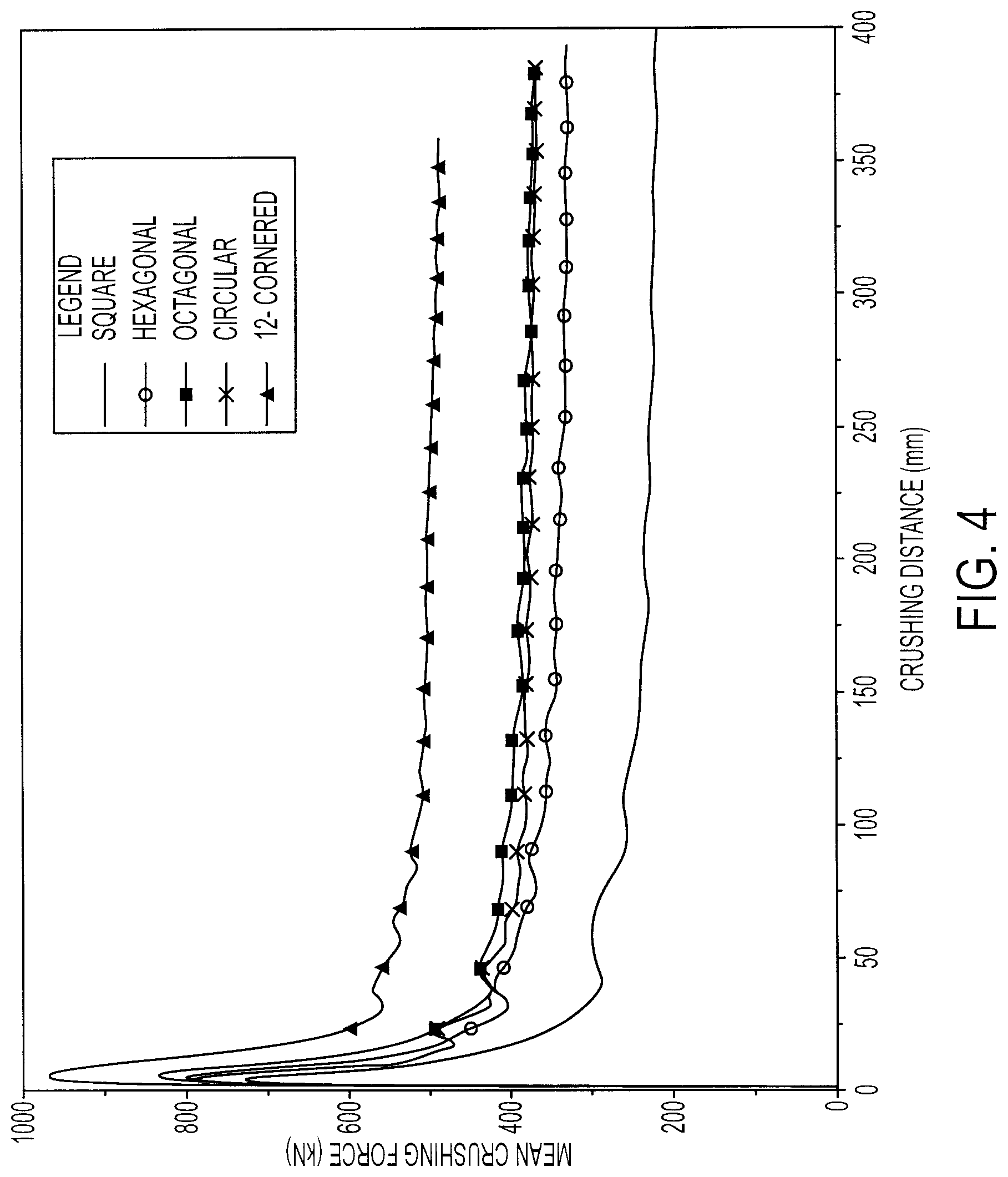
FIG. 4 is a graph of the mean crush force and associated axial crush distance for exemplary strengthening members having the cross sections shown in FIG. 2;
FIGS. 5A-5D illustrate a vehicle front rail without convolutions, having varying cross sections including twelve-cornered cross sections in accordance with the present teachings;
FIGS. 6A-6D illustrate a vehicle front rail with convolutions, having varying cross sections including twelve-cornered cross sections in accordance with the present teachings;
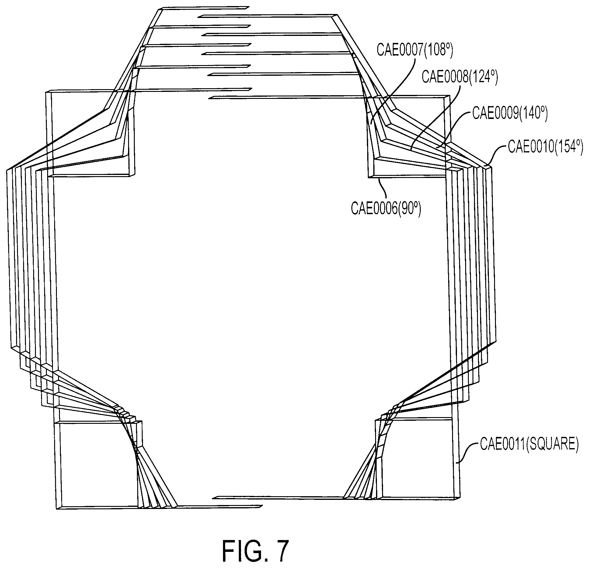
FIG. 7 illustrates geometries of twelve-cornered cross sections of varying shapes and a square cross section having the same thickness and perimeter;
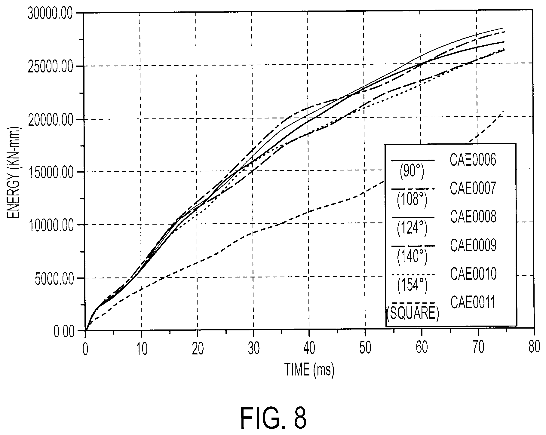
FIG. 8 shows the comparison of the crash energy absorbed (for a given force) by strengthening members having the exemplary cross sections illustrated in FIG. 7;
FIG. 9 is a perspective view of a vehicle frame, according to an exemplary embodiment;
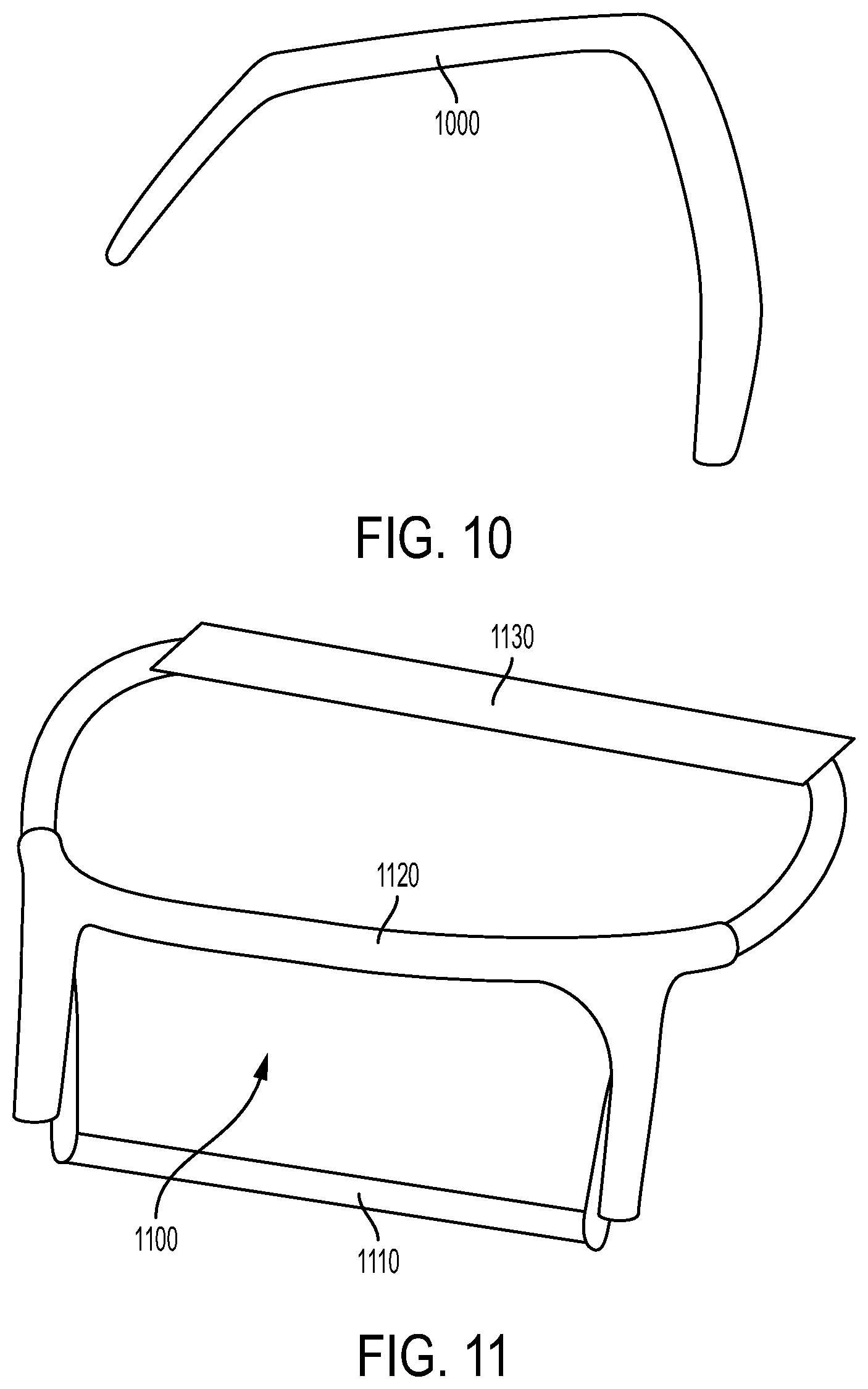
FIG. 10 is a perspective view of a roof structure, according to an exemplary embodiment; and
FIG. 11 is a perspective view of cross members for an engine compartment, according to an exemplary embodiment.
Although the following detailed description makes reference to illustrative embodiments, many alternatives, modifications, and variations thereof will be apparent to those skilled in the art. Accordingly, it is intended that the claimed subject matter be viewed broadly.
DESCRIPTION OF EXEMPLARY EMBODIMENTS
Reference will now be made in detail to various embodiments, examples of which are illustrated in the accompanying drawings. The various exemplary embodiments are not intended to limit the disclosure. To the contrary, the disclosure is intended to cover alternatives, modifications, and equivalents.
The present teachings contemplate providing a strengthening member with a twelve-cornered cross section having a substantially increased stiffness throughout the sides and corners without increasing thickness within the corners. The strengthening member can achieve increased energy absorption and a more stable axial collapse when forces such as front and side impact forces are exerted on the strengthening member. The strengthening member can also possess improved durability and noise-vibration-harshness (NVH) performance due to work hardening on the twelve corners. The degrees of the internal and external angles of the present teachings can achieve the same strength increase as thickened corners, while minimizing mass per unit length of the member and maintaining a high manufacturing feasibility because the member can be formed by bending, rolling, stamping, pressing, hydro-forming, molding, extrusion, cutting, and forging.
An exemplary embodiment of a twelve-cornered cross section for a strengthening member in accordance with the present teachings is illustrated in FIG. 1. As illustrated, the cross section comprises twelve sides having lengths S.sub.1-S.sub.12 and thicknesses T.sub.1-T.sub.12, eight internal corners with angles .sub.i1-.sub.i8 and four external corners with angles .sub.e1-.sub.e4. The internal and external angular degrees can be varied to achieve improved strength and other performance features (e.g., stability of folding pattern) compared to existing 90.degree.-angled cross sections. This improve strength obviates the need for increased corner thickness, which is an unexpected and unpredicted benefit of fine-tuning the internal and external angular degrees of a strengthening member having a twelve-sided cross section. In accordance with various embodiments of the present teachings, each internal angle can range from about 100.degree. to about 110.degree., and each external angle can range from about 105.degree. to about 130.degree.. The lengths S.sub.1-S.sub.12 and thicknesses T.sub.1-T.sub.12 of the sides can be varied to a certain degree, as would be understood by one skilled in the art, for example in accordance with available packaging space within a vehicle.
In certain embodiments of the present teachings a thickness of the sides and corners can range from about 0.7 mm to about 6.0 mm. In certain embodiments, the thickness of the sides is substantially the same as the thickness of the corners.
Conventional strengthening members having square or rectangular cross sections are widely used due to their high manufacturing feasibility. Because a strengthening member with a twelve-cornered cross section in accordance with the present teachings has substantially increased strength and stiffness without requiring thicker corner portions, it has a higher manufacturing feasibility than previously-contemplated twelve-cornered members that have thickened 90.degree. corners. While still providing a desired strength, a strengthening member in accordance with the present teachings can be formed in one or multiple sections by, for example, bending, rolling, stamping, pressing, drawing, hydro-forming, molding, extrusion, cutting, and forging. Thus-formed sections can be joined via welding, adhesive, fastening, or other known joining technologies.
In accordance with certain exemplary embodiments of the present teachings, the thickness of the strengthening member may vary, for example, within one side or from side to side to optimize the overall axial crush and bending performance. Examples of such varied thickness embodiments are illustrated in FIGS. 5D and 6D, which are described in detail below.
In comparing crash energy absorption of strengthening members of varying shapes having the same thickness and perimeter, as illustrated in FIG. 2, for example for an impact with a rigid wall at 35 mph, a twelve-cornered cross section in accordance with the present teachings demonstrated the shortest crush distance and smallest folding length. The twelve-cornered cross section in accordance with the present teachings also demonstrated the most stable axial collapse and the highest crash energy absorption. In fact, a twelve-cornered cross section in accordance with the present teachings can achieve about a 100% increase in crash energy absorption over a square cross section and a 20-30% increase in crash energy absorption over hexagonal and octagonal cross sections. FIG. 3 illustrates an exemplary axial collapse of the strengthening members shown in FIG. 2. As can be seen, the strengthening member having a twelve-cornered cross section in accordance with the present teachings exhibits the shortest crush distance and most stable folding pattern.
FIG. 4 illustrates a graph of mean crush force for an impact with a rigid wall at 35 mph, in kN, exerted axially on exemplary strengthening members having the cross sections shown in FIG. 2. As can be seen, a strengthening member having a twelve-cornered cross section in accordance with the present teachings can sustain a much higher crushing force for a given resulting crushing distance. This allows improved impact energy management while minimizing mass per unit length.
A twelve-cornered cross section in accordance with the present teachings is contemplated for use with a number of structural members such as a front rail (e.g., front rail 910 in frame 900 of FIG. 9), a side rail (e.g., side rail 920 in frame 900 of FIG. 9), a cross member (e.g., cross members 1110, 1120, 1130 for engine compartment 1100 in FIG. 11), roof structures (e.g., roof rail 1000 of FIG. 10), and other components that can benefit from increased crash energy absorption. In addition, the present teachings can be applied to both body-on-frame and unitized vehicles or other type of structures.
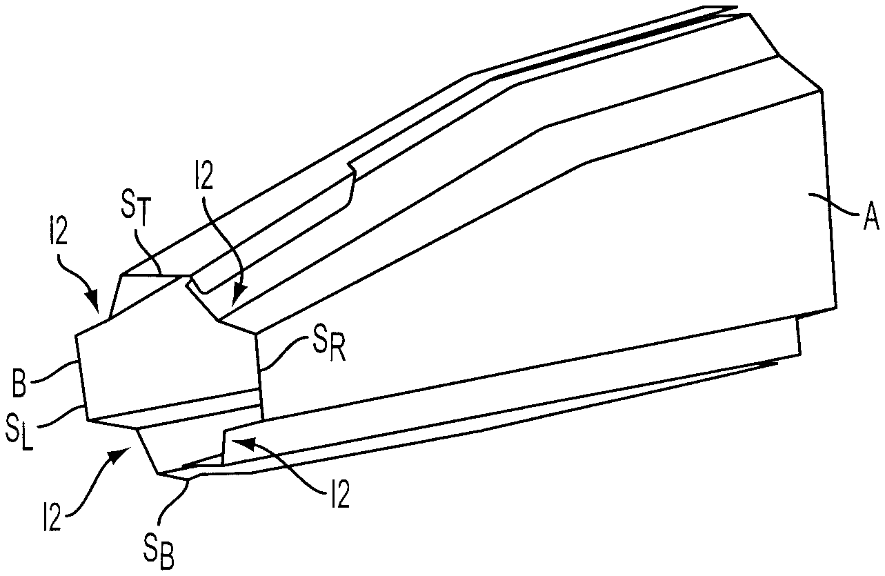
FIGS. 5A-5D illustrate exemplary embodiments of a vehicle front rail having a cross section in accordance with the present teachings. The front rail is of a type without convolutions. FIG. 5A illustrates a front rail having a known, substantially rectangular cross section with four corners 510, 512, 514, 516 of about ninety degrees, and four sides 520, 522, 524, 526. FIGS. 5B through 5D illustrate front rails having twelve-cornered cross sections in accordance with the present teachings, the corner indentations I1 in FIG. 5C being greater than the indentations I2 in FIG. 5B. In these illustrated exemplary embodiments, the rails have a two-part construction comprising pieces A and B. The present teachings contemplate rails of other construction such as one-piece or even 3-or-more piece construction, the number of pieces in FIGS. 5A through 5D being exemplary only.
The embodiments of FIGS. 5B and 5C include top and bottom sides S.sub.B and S.sub.T having substantially the same length as each other, and left and right sides S.sub.L and S.sub.R also having substantially the same length as each other. Piece A includes side S.sub.R and part of sides S.sub.B and S.sub.T. Piece B includes side S.sub.L and part of sides S.sub.B and S.sub.T. To simplify FIGS. 5B-5D, all of the sides S.sub.1 through S.sub.10, as illustrated in FIG. 1, are not labeled but are of course present. Similarly, the eight internal corners (angles: .sub.i1-.sub.i8) and four external corners (angles: .sub.e1-.sub.e4) as illustrated in FIG. 1, are not labeled but are present.
FIG. 5D illustrates a front rail having a twelve-cornered cross section, the rail being formed with different depths of indentations, for example to accommodate packaging constraints of a vehicle's engine compartment. In accordance with such an embodiment needing to have a varied shape to accommodate engine compartment constraints, to achieve optimized axial crush performance, the thicknesses of the sides, angles of the corners, and indentation depths can all be adjusted to provide optimal strength, size and shape. In the example of FIG. 5D, corner indentations I3 and I4 have the different depths, corner indentation I4 being shallower than corner indentation I3. Corner indentations I5 and I6 have substantially the same depth as each other, that depth differing from the depths of corner indentations I3 and I4. The top and bottom sides S.sub.B and S.sub.T have different lengths, with S.sub.T being longer than S.sub.B, and the left and right sides S.sub.L and S.sub.R have differing lengths, with S.sub.R being longer than S.sub.L. The internal and external angles may also differ as a result of the differing side lengths and corner indentation depths. The present teachings also contemplate a twelve-cornered cross section where each of the corner indentations has a different depth and a different angle, and each of the sides has a different length, or where some of the sides have the same length and some of the corner indentations have the same depth and perhaps the same internal and external angles .
For a front rail comprising SAE1010 material, a front rail as illustrated in FIG. 5B (with shallower indentations) can save, for example, about 17% weight compared to a square or rectangular cross section, and a front rail as illustrated in FIG. 5C (with deeper indentations) can save, for example, about 35% weight. For a front rail comprising DP600 material, a front rail as illustrated in FIG. 5B (with shallower indentations) can save, for example, about 23% weight and a front rail as illustrated in FIG. 5C (with deeper indentations) can save, for example, about 47% weight. Such weight savings are realized because the increased strength of the twelve-cornered cross section allows the use of a thinner gauge material to provide the same strength.
FIGS. 6A-6D illustrate exemplary embodiments of a vehicle front rail having a cross section in accordance with the present teachings. The front rail is of a type with convolutions. FIG. 6A illustrates a convoluted front rail having a known, substantially rectangular cross section with four corners 610, 612, 614, 616 of about ninety degrees, and four sides 620, 622, 624, and 626. FIGS. 6B through 6D illustrate convoluted front rails having twelve-cornered cross sections in accordance with the present teachings, the corner indentations I8 in FIG. 6C being greater than the indentations I7 in FIG. 6B. In these illustrated exemplary embodiments, the rails have a two-part construction with pieces C and D. As stated above, the two-piece constructions shown in FIGS. 6B through 6D are exemplary only and the present teachings contemplate rails of other construction such as one-piece or even 3-or-more piece construction.
The embodiments of FIGS. 6B and 6C include top and bottom sides S.sub.B and S.sub.T having substantially the same length as each other, and left and right sides S.sub.L and S.sub.R also having substantially the same length as each other. Piece C includes side S.sub.R and part of sides S.sub.B and S.sub.T. Piece D includes side S.sub.L and part of sides S.sub.B and S.sub.T. To simplify FIGS. 6B-6D, all of the sides S.sub.1 through S.sub.10, as illustrated in FIG. 1, are not labeled but are present. Similarly, the eight internal corners (angles: .sub.i1-.sub.i8) and four external corners (angles: .sub.e1-.sub.e4) as illustrated in FIG. 1, are not labeled but are present.
FIG. 6D illustrates a convoluted front rail having twelve-cornered cross section, the rail being formed with different depths of indentations, for example to accommodate packaging constraints of a vehicle's engine compartment. In accordance with such an embodiment needing to have a varied shape to accommodate engine compartment constraints, to achieve optimized axial crush performance, the thicknesses of the sides, angles of the corners, and indentation depths can all be adjusted to provide optimal strength, size and shape. In the example of FIG. 6D, corner indentations I9 and I10 have the different depths, with corner indentation I10 being shallower than corner indentation I9. Corner indentations I11 and I12 have substantially the same depth as each other, that depth differing from the depths of corner indentations I9 and I10. The top and bottom sides S.sub.B and S.sub.T have different lengths, with S.sub.T being longer than S.sub.B, and the left and right sides S.sub.L and S.sub.R have differing lengths, with S.sub.R being longer than S.sub.L. The internal and external angles may also differ as a result of the differing side lengths and corner indentation depths. The present teachings also contemplate a twelve-cornered cross section where each of the corner indentations has a different depth and a different angle, and each of the sides has a different length, or where some of the sides have the same length and some of the corner indentations have the same depth and perhaps the same internal and external angles .
For a convoluted front rail comprising SAE1010 material, a front rail as illustrated in FIG. 6B (with shallower indentations) can save, for example, about 20% weight compared to a square or rectangular cross section, and a front rail as illustrated in FIG. 6C (with deeper indentations) can save, for example, about 32% weight. For a convoluted front rail comprising DP600 material, a front rail as illustrated in FIG. 6B (with shallower indentations) can save, for example, about 30% weight and a front rail as illustrated in FIG. 6C (with deeper indentations) can save, for example, about 41% weight.
Strengthening members having a variety of cross sections are illustrated in FIG. 7. As can be seen, CAE006 has a twelve-cornered cross section with external angles of 90.degree.. CAE007 has a twelve-cornered cross section with external angles of 108.degree. in accordance with the present teachings. CAE008 has a twelve-cornered cross section with external angles of 124.degree. in accordance with the present teachings. CAE009 has a twelve-cornered cross section with external angles of 140.degree.. CAE010 has a twelve-cornered cross section with external angles of 154.degree.. Finally, CAE011 has a square cross section. A comparison of the axial crush strength of the illustrated square and twelve-cornered cross sections having differing external angles is illustrated in FIG. 8. As can be seen, the overall axial crush strength of the strengthening member having a twelve-cornered cross section is far greater than that of the strengthening member having a square cross section.
As can further be seen, the exemplary strengthening members with twelve-cornered cross sections having external angles of 108.degree. and 124.degree. show an overall increase in axial crush strength over twelve-cornered cross sections having external angles of 90.degree.. In fact, deviation of the angles from 90.degree. such that each internal angle is about the same as other internal angles and ranges from about 100.degree. to about 110.degree., and each external angle is about the same as other external angles and ranges from about 105.degree. to about 130.degree., increases strength without negatively affecting the stability of a crush mode of the strengthening member. Such an increase in strength obviates the need for reinforcing (e.g., thickening) the concave portions at the four corners of the strengthening member, decreasing weight and cost and increasing manufacturing feasibility.
Strengthening members in accordance with the present teachings can comprise, for example, steel, aluminum, magnesium, fiberglass, nylon, plastic, a composite or any other suitable materials.
While the present teachings have been disclosed in terms of exemplary embodiments in order to facilitate a better understanding, it should be appreciated that the present teachings can be embodied in various ways without departing from the scope thereof. Therefore, the invention should be understood to include all possible embodiments which can be embodied without departing from the scope of the invention set out in the appended claims.
For the purposes of this specification and appended claims, unless otherwise indicated, all numbers expressing quantities, percentages or proportions, and other numerical values used in the specification and claims, are to be understood as being modified in all instances by the term "about." Accordingly, unless indicated to the contrary, the numerical parameters set forth in the written description and claims are approximations that may vary depending upon the desired properties sought to be obtained by the present invention. At the very least, and not as an attempt to limit the application of the doctrine of equivalents to the scope of the claims, each numerical parameter should at least be construed in light of the number of reported significant digits and by applying ordinary rounding techniques.
It is noted that, as used in this specification and the appended claims, the singular forms "a," "an," and "the," include plural referents unless expressly and unequivocally limited to one referent. As used herein, the term "include" and its grammatical variants are intended to be non-limiting, such that recitation of items in a list is not to the exclusion of other like items that can be substituted or added to the listed items.
It will be apparent to those skilled in the art that various modifications and variations can be made to the devices and methods of the present disclosure without departing from the scope of its teachings. Other embodiments of the disclosure will be apparent to those skilled in the art from consideration of the specification and practice of the teachings disclosed herein. It is intended that the specification and embodiment described herein be considered as exemplary only.
* * * * *
D00000
D00001
D00002
D00003
D00004
D00005
D00006
D00007
D00008
D00009
P00001
XML
uspto.report is an independent third-party trademark research tool that is not affiliated, endorsed, or sponsored by the United States Patent and Trademark Office (USPTO) or any other governmental organization. The information provided by uspto.report is based on publicly available data at the time of writing and is intended for informational purposes only.
While we strive to provide accurate and up-to-date information, we do not guarantee the accuracy, completeness, reliability, or suitability of the information displayed on this site. The use of this site is at your own risk. Any reliance you place on such information is therefore strictly at your own risk.
All official trademark data, including owner information, should be verified by visiting the official USPTO website at www.uspto.gov. This site is not intended to replace professional legal advice and should not be used as a substitute for consulting with a legal professional who is knowledgeable about trademark law.