Implantable device for increasing tear production
Loudin , et al.
U.S. patent number 10,610,695 [Application Number 15/699,905] was granted by the patent office on 2020-04-07 for implantable device for increasing tear production. This patent grant is currently assigned to Oculeve, Inc.. The grantee listed for this patent is Oculeve, Inc.. Invention is credited to Douglas Michael Ackermann, Anand Doraiswamy, Manfred Franke, Daniel N. Hamilton, James Donald Loudin.


| United States Patent | 10,610,695 |
| Loudin , et al. | April 7, 2020 |
Implantable device for increasing tear production
Abstract
Described here are devices, systems, and methods for increasing tear production by stimulating the cornea, conjunctiva, and/or subconjunctiva. In some variations, the devices may be in the form of a contact lens. The contact lens may comprise a lens body and a stimulator chip, where the stimulator chip is embedded in the lens body. An external power source wirelessly transmits energy to the stimulator chip, where the stimulator chip may convert the energy to an electric waveform to stimulate the cornea, conjunctiva, and/or subconjunctiva. Stimulation may activate the lacrimal reflex to increase tear production. The devices and systems for increasing tear production may be used in methods of treating dry eye, reducing the symptoms of tired eye, increasing comfort for contact lens wearers, and extending the number of years a contact lens user can wear contacts. Also described are methods of manufacturing a contact lens.
| Inventors: | Loudin; James Donald (Alhambra, CA), Franke; Manfred (Valencia, CA), Hamilton; Daniel N. (Napa, CA), Doraiswamy; Anand (San Francisco, CA), Ackermann; Douglas Michael (Reno, NV) | ||||||||||
|---|---|---|---|---|---|---|---|---|---|---|---|
| Applicant: |
|
||||||||||
| Assignee: | Oculeve, Inc. (Madison,
NJ) |
||||||||||
| Family ID: | 55761600 | ||||||||||
| Appl. No.: | 15/699,905 | ||||||||||
| Filed: | September 8, 2017 |
Prior Publication Data
| Document Identifier | Publication Date | |
|---|---|---|
| US 20170368359 A1 | Dec 28, 2017 | |
Related U.S. Patent Documents
| Application Number | Filing Date | Patent Number | Issue Date | ||
|---|---|---|---|---|---|
| 14920847 | Oct 22, 2015 | 9764150 | |||
| 62067395 | Oct 22, 2014 | ||||
| Current U.S. Class: | 1/1 |
| Current CPC Class: | B29D 11/00038 (20130101); A61N 1/3756 (20130101); B29D 11/00826 (20130101); A61N 1/3787 (20130101); A61N 1/3606 (20130101); A61N 1/36046 (20130101); A61N 1/36121 (20130101) |
| Current International Class: | A61N 1/36 (20060101); A61N 1/378 (20060101); A61N 1/375 (20060101); B29D 11/00 (20060101) |
References Cited [Referenced By]
U.S. Patent Documents
| 2512882 | June 1950 | Truesdale |
| 2525381 | October 1950 | Tower |
| 3620219 | November 1971 | Barker |
| 3709228 | January 1973 | Barker |
| 3885550 | May 1975 | MacLeod |
| D257495 | November 1980 | Bros et al. |
| 4495676 | January 1985 | Hartmetz |
| 4520825 | June 1985 | Thompson et al. |
| 4539988 | September 1985 | Shirley et al. |
| 4590942 | May 1986 | Brenman et al. |
| 4628933 | December 1986 | Michelson |
| 4681121 | July 1987 | Kobal |
| 4684362 | August 1987 | Holt |
| 4706680 | November 1987 | Keusch et al. |
| 4735207 | April 1988 | Nambu et al. |
| 4777954 | October 1988 | Keusch et al. |
| 4780932 | November 1988 | Bowman et al. |
| 4868154 | September 1989 | Gilbard et al. |
| 4926880 | May 1990 | Claude et al. |
| 4957480 | September 1990 | Morenings |
| 4988358 | January 1991 | Eppley et al. |
| 5025807 | June 1991 | Zabara |
| 5072724 | December 1991 | Marcus |
| 5078733 | January 1992 | Eveleigh et al. |
| 5090422 | February 1992 | Dahl et al. |
| 5099829 | March 1992 | Wu |
| 5147284 | September 1992 | Fedorov et al. |
| 5324316 | June 1994 | Schulman et al. |
| 5342410 | August 1994 | Braverman |
| 5345948 | September 1994 | O'Donnell, Jr. |
| 5352445 | October 1994 | Lavaux |
| 5360438 | November 1994 | Fisher |
| 5498681 | March 1996 | Askari et al. |
| 5514131 | May 1996 | Edwards et al. |
| 5533470 | July 1996 | Rose |
| 5545617 | August 1996 | Dartt et al. |
| 5571101 | November 1996 | Ellman et al. |
| 5607461 | March 1997 | Lathrop |
| 5611970 | March 1997 | Apollonio et al. |
| 5640978 | June 1997 | Wong |
| 5683436 | November 1997 | Mendes et al. |
| 5697957 | December 1997 | Noren et al. |
| 5707400 | January 1998 | Terry et al. |
| 5713833 | February 1998 | Milligan |
| 5720773 | February 1998 | Lopez-Claros |
| 5733282 | March 1998 | Ellman et al. |
| 5735817 | April 1998 | Shantha |
| 5792100 | August 1998 | Shantha |
| 5794614 | August 1998 | Gruenke et al. |
| 5800685 | September 1998 | Perrault |
| 5843140 | December 1998 | Strojnik |
| 5900407 | May 1999 | Yerxa et al. |
| 5904658 | May 1999 | Niederauer et al. |
| 5935155 | August 1999 | Humayun et al. |
| 5948006 | September 1999 | Mann |
| 6001088 | December 1999 | Roberts et al. |
| 6020445 | February 2000 | Vanderlaan et al. |
| 6035236 | March 2000 | Jarding et al. |
| 6050999 | April 2000 | Paraschac et al. |
| 6051017 | April 2000 | Loeb et al. |
| 6083251 | July 2000 | Shindo |
| 6102847 | August 2000 | Stielau |
| 6152916 | November 2000 | Bige |
| 6200626 | March 2001 | Grobe, III et al. |
| 6205359 | March 2001 | Boveja |
| 6208902 | March 2001 | Boveja |
| 6240316 | May 2001 | Richmond et al. |
| 6246911 | June 2001 | Seligman |
| 6270796 | August 2001 | Weinstein |
| 6272382 | August 2001 | Faltys et al. |
| 6275737 | August 2001 | Mann |
| 6277855 | August 2001 | Yerxa |
| 6284765 | September 2001 | Caffrey |
| 6324429 | November 2001 | Shire et al. |
| 6327504 | December 2001 | Dolgin et al. |
| 6366814 | April 2002 | Boveja et al. |
| 6405079 | June 2002 | Ansarinia |
| 6438398 | August 2002 | Pflugfelder et al. |
| 6458157 | October 2002 | Suaning |
| 6505077 | January 2003 | Kast et al. |
| 6526318 | February 2003 | Ansarinia |
| 6535766 | March 2003 | Thompson et al. |
| 6537265 | March 2003 | Thanavala et al. |
| 6539253 | March 2003 | Thompson et al. |
| 6562036 | May 2003 | Ellman et al. |
| 6564102 | May 2003 | Boveja |
| 6578579 | June 2003 | Burnside et al. |
| 6604528 | August 2003 | Duncan |
| 6641799 | November 2003 | Goldberg |
| 6658301 | December 2003 | Loeb et al. |
| 6662052 | December 2003 | Sarwal et al. |
| 6684879 | February 2004 | Coffee et al. |
| 6701189 | March 2004 | Fang et al. |
| 6748951 | June 2004 | Schmidt |
| 6792314 | September 2004 | Byers et al. |
| 6829508 | December 2004 | Schulman et al. |
| 6853858 | February 2005 | Shalev |
| 6871099 | March 2005 | Whitehurst et al. |
| 6879859 | April 2005 | Boveja |
| 6885888 | April 2005 | Rezai |
| 6895279 | May 2005 | Loeb et al. |
| 7024241 | April 2006 | Bornzin et al. |
| 7054692 | May 2006 | Whitehurst et al. |
| 7067307 | June 2006 | Hochleitner et al. |
| 7069084 | June 2006 | Yee |
| 7117033 | October 2006 | Shalev et al. |
| 7142909 | November 2006 | Greenberg et al. |
| 7146209 | December 2006 | Gross et al. |
| 7169163 | January 2007 | Becker |
| 7190998 | March 2007 | Shalev et al. |
| 7225032 | May 2007 | Schmeling et al. |
| 7228184 | June 2007 | Heath |
| 7247692 | July 2007 | Laredo |
| 7317947 | January 2008 | Wahlstrand et al. |
| 7330762 | February 2008 | Boveja et al. |
| 7346389 | March 2008 | Newsome |
| 7346398 | March 2008 | Gross et al. |
| 7369897 | May 2008 | Boveja et al. |
| 7442191 | October 2008 | Hovda et al. |
| 7460911 | December 2008 | Cosendai et al. |
| 7477947 | January 2009 | Pines et al. |
| 7502652 | March 2009 | Gaunt et al. |
| 7547447 | June 2009 | Yiu et al. |
| 7565204 | July 2009 | Matei et al. |
| 7599737 | October 2009 | Yomtov et al. |
| 7636597 | December 2009 | Gross et al. |
| 7650186 | January 2010 | Hastings et al. |
| D613408 | April 2010 | Gausmann et al. |
| D614303 | April 2010 | Gausmann et al. |
| D614774 | April 2010 | Gausmann et al. |
| 7725176 | May 2010 | Schuler et al. |
| 7725195 | May 2010 | Lima et al. |
| D617443 | June 2010 | Grenon et al. |
| 7758190 | July 2010 | Korb et al. |
| 7778703 | August 2010 | Gross et al. |
| 7778711 | August 2010 | Ben-David et al. |
| 7792591 | September 2010 | Rooney et al. |
| 7805200 | September 2010 | Kast et al. |
| 7805202 | September 2010 | Kuzma et al. |
| 7805203 | September 2010 | Ben-David et al. |
| 7809442 | October 2010 | Bolea et al. |
| 7835794 | November 2010 | Greenberg et al. |
| 7846124 | December 2010 | Becker |
| 7860570 | December 2010 | Whitehurst et al. |
| 7873421 | January 2011 | Karell |
| 7879079 | February 2011 | Tu et al. |
| D638128 | May 2011 | Prokop et al. |
| 7981095 | July 2011 | Grenon et al. |
| 7993381 | August 2011 | Mac et al. |
| 7998202 | August 2011 | Lesh |
| 8002783 | August 2011 | Vercellotti et al. |
| 8019419 | September 2011 | Panescu et al. |
| 8019441 | September 2011 | Wallace et al. |
| 8080047 | December 2011 | Yu |
| 8083787 | December 2011 | Korb et al. |
| 8145322 | March 2012 | Yao et al. |
| 8155746 | April 2012 | Maltan et al. |
| 8165680 | April 2012 | Greenberg et al. |
| 8204591 | June 2012 | Ben-David et al. |
| 8231218 | July 2012 | Hong et al. |
| 8251983 | August 2012 | Larson et al. |
| 8295529 | October 2012 | Petersen et al. |
| 8318070 | November 2012 | Shiah et al. |
| D681839 | May 2013 | Nathanson |
| 8489189 | July 2013 | Tronnes |
| 8494641 | July 2013 | Boling et al. |
| 8521292 | August 2013 | Wei et al. |
| 8626298 | January 2014 | Simon |
| 8676324 | March 2014 | Simon et al. |
| 8728136 | May 2014 | Feldman |
| 8918181 | December 2014 | Ackermann et al. |
| 8936594 | January 2015 | Wolf et al. |
| 8986301 | March 2015 | Wolf et al. |
| 8996137 | March 2015 | Ackermann et al. |
| 9079042 | July 2015 | Tiedtke et al. |
| 9095723 | August 2015 | Ackermann et al. |
| 9265956 | February 2016 | Ackermann et al. |
| 9440065 | September 2016 | Ackermann et al. |
| 9687652 | June 2017 | Franke et al. |
| 9717627 | August 2017 | Kuzma et al. |
| 9737702 | August 2017 | Ackermann et al. |
| 9737712 | August 2017 | Franke et al. |
| 9764150 | September 2017 | Loudin et al. |
| 9770583 | September 2017 | Gupta et al. |
| 9821159 | November 2017 | Ackermann et al. |
| 9956397 | May 2018 | Loudin et al. |
| D826420 | August 2018 | Ackermann et al. |
| 10143846 | December 2018 | Ackermann et al. |
| D837396 | January 2019 | Ackermann et al. |
| 10207108 | February 2019 | Franke et al. |
| 2001/0018918 | September 2001 | Burnside et al. |
| 2001/0020177 | September 2001 | Gruzdowich et al. |
| 2002/0013594 | January 2002 | Dinger et al. |
| 2002/0035358 | March 2002 | Wang |
| 2002/0049290 | April 2002 | Vanderbilt |
| 2002/0188331 | December 2002 | Fang et al. |
| 2003/0014089 | January 2003 | Chow |
| 2003/0045909 | March 2003 | Gross et al. |
| 2003/0045911 | March 2003 | Bruchmann et al. |
| 2003/0114899 | June 2003 | Woods et al. |
| 2003/0120323 | June 2003 | Meadows et al. |
| 2003/0130809 | July 2003 | Cohen et al. |
| 2003/0139784 | July 2003 | Morimoto et al. |
| 2003/0176898 | September 2003 | Gross et al. |
| 2003/0192784 | October 2003 | Zhou |
| 2003/0229381 | December 2003 | Hochmair et al. |
| 2003/0233134 | December 2003 | Greenberg et al. |
| 2003/0233135 | December 2003 | Yee |
| 2004/0050392 | March 2004 | Tu et al. |
| 2004/0059466 | March 2004 | Block et al. |
| 2004/0098036 | May 2004 | Bergersen |
| 2004/0098067 | May 2004 | Ohta et al. |
| 2004/0127942 | July 2004 | Yomtov et al. |
| 2004/0138646 | July 2004 | Walla |
| 2004/0147973 | July 2004 | Hauser et al. |
| 2004/0151930 | August 2004 | Rouns et al. |
| 2004/0220644 | November 2004 | Shalev et al. |
| 2005/0004621 | January 2005 | Boveja et al. |
| 2005/0004625 | January 2005 | Chow |
| 2005/0010250 | January 2005 | Schuler et al. |
| 2005/0010266 | January 2005 | Bogdanowicz |
| 2005/0101967 | May 2005 | Weber |
| 2005/0101994 | May 2005 | Yamazaki et al. |
| 2005/0105046 | May 2005 | Tung |
| 2005/0137276 | June 2005 | Yahiaoui et al. |
| 2005/0159790 | July 2005 | Shalev |
| 2005/0197675 | September 2005 | David et al. |
| 2005/0251061 | November 2005 | Schuler et al. |
| 2005/0256570 | November 2005 | Azar |
| 2005/0267542 | December 2005 | David et al. |
| 2005/0268472 | December 2005 | Bourilkov et al. |
| 2006/0004423 | January 2006 | Boveja et al. |
| 2006/0018872 | January 2006 | Tew et al. |
| 2006/0074450 | April 2006 | Boveja et al. |
| 2006/0089673 | April 2006 | Schultheiss et al. |
| 2006/0095077 | May 2006 | Tronnes et al. |
| 2006/0095108 | May 2006 | Chowdhury et al. |
| 2006/0100668 | May 2006 | Ben-David et al. |
| 2006/0107958 | May 2006 | Sleeper |
| 2006/0142822 | June 2006 | Tulgar |
| 2006/0161225 | July 2006 | Sormann et al. |
| 2006/0195169 | August 2006 | Gross et al. |
| 2006/0206155 | September 2006 | Ben-David et al. |
| 2006/0206162 | September 2006 | Wahlstrand et al. |
| 2006/0216317 | September 2006 | Reinhard et al. |
| 2006/0235430 | October 2006 | Le et al. |
| 2006/0239482 | October 2006 | Hatoum et al. |
| 2006/0259098 | November 2006 | Erickson |
| 2006/0271024 | November 2006 | Gertner et al. |
| 2006/0271108 | November 2006 | Libbus et al. |
| 2006/0276738 | December 2006 | Becker |
| 2007/0031341 | February 2007 | DiMauro et al. |
| 2007/0038250 | February 2007 | He et al. |
| 2007/0038267 | February 2007 | Shodo et al. |
| 2007/0060815 | March 2007 | Martin et al. |
| 2007/0060954 | March 2007 | Cameron et al. |
| 2007/0083245 | April 2007 | Lamensdorf et al. |
| 2007/0123938 | May 2007 | Haller et al. |
| 2007/0135868 | June 2007 | Shi et al. |
| 2007/0150034 | June 2007 | Rooney et al. |
| 2007/0219600 | September 2007 | Gertner et al. |
| 2007/0237797 | October 2007 | Peyman |
| 2007/0237825 | October 2007 | Levy et al. |
| 2007/0248930 | October 2007 | Brawn |
| 2007/0250119 | October 2007 | Tyler et al. |
| 2007/0250135 | October 2007 | Bartz-Schmidt et al. |
| 2007/0255333 | November 2007 | Giftakis et al. |
| 2007/0276314 | November 2007 | Becker |
| 2007/0276451 | November 2007 | Rigaux |
| 2007/0295327 | December 2007 | Bottomley |
| 2007/0299420 | December 2007 | Peyman |
| 2007/0299462 | December 2007 | Becker |
| 2008/0009897 | January 2008 | Duran Von Arx |
| 2008/0021515 | January 2008 | Horsager et al. |
| 2008/0082057 | April 2008 | Korb et al. |
| 2008/0082131 | April 2008 | Llanos |
| 2008/0109054 | May 2008 | Hastings et al. |
| 2008/0114424 | May 2008 | Grenon et al. |
| 2008/0132933 | June 2008 | Gerber |
| 2008/0140141 | June 2008 | Ben-David et al. |
| 2008/0183242 | July 2008 | Tano et al. |
| 2008/0183243 | July 2008 | Shodo et al. |
| 2008/0208287 | August 2008 | Palermo et al. |
| 2008/0208335 | August 2008 | Blum |
| 2008/0221642 | September 2008 | Humayun et al. |
| 2008/0269648 | October 2008 | Bock |
| 2008/0288036 | November 2008 | Greenberg et al. |
| 2008/0294066 | November 2008 | Hetling et al. |
| 2009/0005835 | January 2009 | Greenberg et al. |
| 2009/0012573 | January 2009 | Karell |
| 2009/0018582 | January 2009 | Ishikawa et al. |
| 2009/0024187 | January 2009 | Erickson et al. |
| 2009/0024189 | January 2009 | Lee et al. |
| 2009/0036945 | February 2009 | Chancellor et al. |
| 2009/0043185 | February 2009 | Mcadams et al. |
| 2009/0056709 | March 2009 | Worsoff |
| 2009/0099600 | April 2009 | Moore et al. |
| 2009/0099623 | April 2009 | Bentwich |
| 2009/0099626 | April 2009 | de Juan, Jr. et al. |
| 2009/0101139 | April 2009 | Karell |
| 2009/0124965 | May 2009 | Greenberg et al. |
| 2009/0138061 | May 2009 | Stephens et al. |
| 2009/0156581 | June 2009 | Dillon et al. |
| 2009/0157142 | June 2009 | Cauller et al. |
| 2009/0157145 | June 2009 | Cauller |
| 2009/0157147 | June 2009 | Cauller et al. |
| 2009/0192571 | July 2009 | Stett et al. |
| 2009/0192575 | July 2009 | Carbunaru et al. |
| 2009/0204142 | August 2009 | Becker |
| 2009/0239235 | September 2009 | Demaria et al. |
| 2009/0241840 | October 2009 | Mills |
| 2009/0264966 | October 2009 | Blum et al. |
| 2009/0281594 | November 2009 | King et al. |
| 2009/0281596 | November 2009 | King et al. |
| 2009/0299418 | December 2009 | Shalev et al. |
| 2009/0306738 | December 2009 | Weiss et al. |
| 2009/0312818 | December 2009 | Horsager et al. |
| 2010/0030150 | February 2010 | Paques et al. |
| 2010/0076423 | March 2010 | Muller |
| 2010/0087896 | April 2010 | McCreery |
| 2010/0094280 | April 2010 | Muller |
| 2010/0100165 | April 2010 | Swanson et al. |
| 2010/0139002 | June 2010 | Walker et al. |
| 2010/0152708 | June 2010 | Li et al. |
| 2010/0161004 | June 2010 | Najafi et al. |
| 2010/0168513 | July 2010 | Pless et al. |
| 2010/0179468 | July 2010 | Becker |
| 2010/0211132 | August 2010 | Nimmagadda et al. |
| 2010/0241195 | September 2010 | Meadows et al. |
| 2010/0274164 | October 2010 | Juto |
| 2010/0274224 | October 2010 | Jain et al. |
| 2010/0274313 | October 2010 | Boling et al. |
| 2010/0280509 | November 2010 | Muller et al. |
| 2010/0288275 | November 2010 | Djupesland et al. |
| 2010/0311688 | December 2010 | Chapin et al. |
| 2010/0318159 | December 2010 | Aghassian et al. |
| 2011/0021975 | January 2011 | Covello |
| 2011/0028807 | February 2011 | Abreu |
| 2011/0028883 | February 2011 | Juan, Jr. et al. |
| 2011/0076775 | March 2011 | Stewart et al. |
| 2011/0077551 | March 2011 | Videbaek |
| 2011/0077698 | March 2011 | Tsampazis et al. |
| 2011/0081333 | April 2011 | Shantha et al. |
| 2011/0082518 | April 2011 | Filippello |
| 2011/0093043 | April 2011 | Torgerson et al. |
| 2011/0151393 | June 2011 | Frey et al. |
| 2011/0152969 | June 2011 | Zehnder et al. |
| 2011/0184490 | July 2011 | Horsager et al. |
| 2011/0202121 | August 2011 | Wen |
| 2011/0218590 | September 2011 | Degiorgio et al. |
| 2011/0234971 | September 2011 | Yeh |
| 2011/0270067 | November 2011 | Faraji |
| 2011/0270348 | November 2011 | Goetz |
| 2011/0275734 | November 2011 | Scales et al. |
| 2011/0276107 | November 2011 | Simon et al. |
| 2011/0282251 | November 2011 | Baker et al. |
| 2011/0295336 | December 2011 | Sharma et al. |
| 2011/0313330 | December 2011 | Loushin et al. |
| 2011/0313480 | December 2011 | De Vos |
| 2011/0313481 | December 2011 | De Vos |
| 2011/0313488 | December 2011 | Hincapie Ordonez et al. |
| 2012/0053648 | March 2012 | Neher et al. |
| 2012/0112903 | May 2012 | Kaib et al. |
| 2012/0130398 | May 2012 | Ackermann et al. |
| 2012/0133887 | May 2012 | Huang |
| 2012/0197338 | August 2012 | Su et al. |
| 2012/0232615 | September 2012 | Barolat et al. |
| 2012/0232618 | September 2012 | Feldman |
| 2012/0234332 | September 2012 | Shantha |
| 2012/0253249 | October 2012 | Wilson et al. |
| 2012/0298105 | November 2012 | Osorio et al. |
| 2012/0315329 | December 2012 | Ahn et al. |
| 2012/0316557 | December 2012 | Sartor et al. |
| 2012/0323214 | December 2012 | Shantha |
| 2012/0323227 | December 2012 | Wolf et al. |
| 2012/0323232 | December 2012 | Wolf et al. |
| 2012/0330376 | December 2012 | Flynn et al. |
| 2013/0006095 | January 2013 | Jenkins et al. |
| 2013/0006326 | January 2013 | Ackermann |
| 2013/0053733 | February 2013 | Korb et al. |
| 2013/0053737 | February 2013 | Scerbo |
| 2013/0065765 | March 2013 | Selifonov et al. |
| 2013/0158451 | June 2013 | Juto et al. |
| 2013/0158626 | June 2013 | Degiorgio et al. |
| 2013/0172790 | July 2013 | Badawi |
| 2013/0178937 | July 2013 | Vassallo et al. |
| 2013/0253387 | September 2013 | Bonutti et al. |
| 2013/0261706 | October 2013 | Mirro et al. |
| 2013/0270491 | October 2013 | Park et al. |
| 2013/0274824 | October 2013 | Otto et al. |
| 2013/0274831 | October 2013 | Otto et al. |
| 2013/0304154 | November 2013 | Goodman et al. |
| 2013/0310887 | November 2013 | Curtis |
| 2013/0336557 | December 2013 | Cruzat et al. |
| 2014/0012182 | January 2014 | Shantha |
| 2014/0056815 | February 2014 | Peyman |
| 2014/0081353 | March 2014 | Cook et al. |
| 2014/0088463 | March 2014 | Wolf et al. |
| 2014/0156000 | June 2014 | Campin et al. |
| 2014/0163580 | June 2014 | Tischendorf et al. |
| 2014/0214115 | July 2014 | Greiner et al. |
| 2014/0214118 | July 2014 | Greiner et al. |
| 2014/0214120 | July 2014 | Simon et al. |
| 2014/0214124 | July 2014 | Greiner et al. |
| 2014/0214125 | July 2014 | Greiner et al. |
| 2014/0257205 | September 2014 | Schaller |
| 2014/0257433 | September 2014 | Ackermann et al. |
| 2014/0277429 | September 2014 | Kuzma |
| 2014/0316310 | October 2014 | Ackermann et al. |
| 2014/0316396 | October 2014 | Wolf et al. |
| 2014/0316485 | October 2014 | Ackermann et al. |
| 2014/0362339 | December 2014 | Imafuku |
| 2014/0371565 | December 2014 | Glasser |
| 2014/0371812 | December 2014 | Ackermann et al. |
| 2015/0088156 | March 2015 | Ackermann et al. |
| 2015/0238754 | August 2015 | Loudin et al. |
| 2015/0335900 | November 2015 | Ackermann et al. |
| 2015/0362755 | December 2015 | Lee et al. |
| 2016/0022992 | January 2016 | Franke et al. |
| 2016/0058615 | March 2016 | Camras |
| 2016/0080720 | March 2016 | Fullam |
| 2016/0114163 | April 2016 | Franke et al. |
| 2016/0114172 | April 2016 | Loudin et al. |
| 2016/0121118 | May 2016 | Franke et al. |
| 2016/0158548 | June 2016 | Ackermann et al. |
| 2016/0270656 | September 2016 | Samec et al. |
| 2016/0367795 | December 2016 | Ackermann et al. |
| 2016/0367806 | December 2016 | Kahook |
| 2017/0049619 | February 2017 | Kahook |
| 2017/0157401 | June 2017 | Loudin et al. |
| 2017/0188947 | July 2017 | Connor |
| 2017/0239459 | August 2017 | Loudin et al. |
| 2017/0252563 | September 2017 | Franke et al. |
| 2017/0312521 | November 2017 | Franke et al. |
| 2017/0340884 | November 2017 | Franke et al. |
| 2017/0354536 | December 2017 | Kuzma et al. |
| 2017/0368332 | December 2017 | Ackermann et al. |
| 2017/0368333 | December 2017 | Loudin et al. |
| 2018/0064940 | March 2018 | Ackermann et al. |
| 2018/0064941 | March 2018 | Ackermann et al. |
| 2018/0064942 | March 2018 | Franke et al. |
| 2018/0153394 | June 2018 | Franke et al. |
| 2018/0154137 | June 2018 | Ackermann et al. |
| 2018/0154161 | June 2018 | Ackermann et al. |
| 2018/0161579 | June 2018 | Franke et al. |
| 2018/0280688 | October 2018 | Loudin et al. |
| 2019/0022392 | January 2019 | Franke et al. |
| 2019/0167978 | June 2019 | Ackermann et al. |
| 2019/0217095 | July 2019 | Franke et al. |
| 1488331 | Apr 2004 | CN | |||
| 101087822 | Dec 2007 | CN | |||
| 101503491 | Aug 2009 | CN | |||
| 101589085 | Nov 2009 | CN | |||
| 101939043 | Jan 2011 | CN | |||
| 102266592 | Dec 2011 | CN | |||
| 103467652 | Dec 2013 | CN | |||
| 102006048819 | Apr 2008 | DE | |||
| 0109935 | May 1984 | EP | |||
| 1 497 483 | Jan 2005 | EP | |||
| 1 651 307 | May 2006 | EP | |||
| 1 919 553 | May 2008 | EP | |||
| 1 958 661 | Aug 2008 | EP | |||
| 2 205 193 | Jul 2010 | EP | |||
| 2 205 314 | Jul 2010 | EP | |||
| 3263175 | Jan 2018 | EP | |||
| 2129690 | Mar 1987 | GB | |||
| 2456002 | Jul 2009 | GB | |||
| 2102681-0001 | Oct 2012 | HK | |||
| 2199000-0001 | Mar 2013 | HK | |||
| S60-500241 | Feb 1985 | JP | |||
| 2002-519138 | Jul 2002 | JP | |||
| 2002-325851 | Nov 2002 | JP | |||
| 2002-539859 | Nov 2002 | JP | |||
| 2004-508847 | Mar 2004 | JP | |||
| 2004-526510 | Sep 2004 | JP | |||
| 2005-502409 | Jan 2005 | JP | |||
| 2005-052461 | Mar 2005 | JP | |||
| 2005-144178 | Jun 2005 | JP | |||
| 2005-521489 | Jul 2005 | JP | |||
| 2005-528169 | Sep 2005 | JP | |||
| 2006-515900 | Jun 2006 | JP | |||
| 2006-311917 | Nov 2006 | JP | |||
| 2007-044323 | Feb 2007 | JP | |||
| 2007-528751 | Oct 2007 | JP | |||
| 2008-55000 | Mar 2008 | JP | |||
| 2008-183248 | Aug 2008 | JP | |||
| 2008-541850 | Nov 2008 | JP | |||
| 2009-506836 | Feb 2009 | JP | |||
| 2009-523503 | Jun 2009 | JP | |||
| 2010-505563 | Feb 2010 | JP | |||
| 2010-051562 | Mar 2010 | JP | |||
| 2010-506654 | Mar 2010 | JP | |||
| 2010-537777 | Dec 2010 | JP | |||
| 2011-030734 | Feb 2011 | JP | |||
| 2011-524780 | Sep 2011 | JP | |||
| 2012-100708 | May 2012 | JP | |||
| 2012-115545 | Jun 2012 | JP | |||
| 2012-200558 | Oct 2012 | JP | |||
| 2013-528416 | Jul 2013 | JP | |||
| 2338492 | Nov 2008 | RU | |||
| WO-00/01320 | Jan 2000 | WO | |||
| WO-00/56393 | Sep 2000 | WO | |||
| WO-00/62672 | Oct 2000 | WO | |||
| WO-01/85094 | Nov 2001 | WO | |||
| WO-02/078592 | Oct 2002 | WO | |||
| WO-03/023907 | Mar 2003 | WO | |||
| WO-03/082080 | Oct 2003 | WO | |||
| WO-2003/087433 | Oct 2003 | WO | |||
| WO-03/101535 | Dec 2003 | WO | |||
| WO-2004/026106 | Apr 2004 | WO | |||
| WO-2004/026106 | Apr 2004 | WO | |||
| WO-2004/043217 | May 2004 | WO | |||
| WO-2004/043217 | May 2004 | WO | |||
| WO-2004/091453 | Oct 2004 | WO | |||
| WO-2004/112893 | Dec 2004 | WO | |||
| WO-2004/112893 | Dec 2004 | WO | |||
| WO-2005/007234 | Jan 2005 | WO | |||
| WO-2005/007234 | Jan 2005 | WO | |||
| WO-2005/030025 | Apr 2005 | WO | |||
| WO-2005/030025 | Apr 2005 | WO | |||
| WO-2005/060984 | Jul 2005 | WO | |||
| WO-2006/127366 | Nov 2006 | WO | |||
| WO-2007/028003 | Mar 2007 | WO | |||
| WO-2007/079543 | Jul 2007 | WO | |||
| WO-2008/048321 | Apr 2008 | WO | |||
| WO-2008/156501 | Dec 2008 | WO | |||
| WO-2008/156501 | Dec 2008 | WO | |||
| WO-2009/035571 | Mar 2009 | WO | |||
| WO-2009/035571 | Mar 2009 | WO | |||
| WO-2009/048580 | Apr 2009 | WO | |||
| WO-2009/070709 | Jun 2009 | WO | |||
| WO-2009/154457 | Dec 2009 | WO | |||
| WO-2010/003011 | Jan 2010 | WO | |||
| WO-2010/027743 | Mar 2010 | WO | |||
| WO-2010/069317 | Jun 2010 | WO | |||
| WO-2010/099818 | Sep 2010 | WO | |||
| WO-2010/123704 | Oct 2010 | WO | |||
| WO-2011/011373 | Jan 2011 | WO | |||
| WO-2012/068247 | May 2012 | WO | |||
| WO-2012/139063 | Oct 2012 | WO | |||
| WO-2012/139063 | Oct 2012 | WO | |||
| WO-2012/155188 | Nov 2012 | WO | |||
| WO-2013/055940 | Apr 2013 | WO | |||
| WO-2013/055940 | Apr 2013 | WO | |||
| WO-2013/157320 | Oct 2013 | WO | |||
| WO-2013/162793 | Oct 2013 | WO | |||
| WO-2013/165697 | Nov 2013 | WO | |||
| WO-2013/166353 | Nov 2013 | WO | |||
| WO-2014/138709 | Sep 2014 | WO | |||
| WO-2014/165124 | Oct 2014 | WO | |||
| WO-2014/172693 | Oct 2014 | WO | |||
| WO-2014/172693 | Oct 2014 | WO | |||
| WO-2015/130707 | Sep 2015 | WO | |||
| WO-2015/130707 | Sep 2015 | WO | |||
| WO-2016/015025 | Jan 2016 | WO | |||
| WO-2016/025323 | Feb 2016 | WO | |||
| WO-2016/065211 | Apr 2016 | WO | |||
| WO-2016/065213 | Apr 2016 | WO | |||
| WO-2016/065215 | Apr 2016 | WO | |||
| WO-2017/192572 | Nov 2017 | WO | |||
| WO-2014/153218 | Sep 2019 | WO | |||
Other References
|
Olsen et al. "Human sclera: Thickness and surface area". American Journal of Ophthalmology. Feb. 1998, vol. 125, Issue 2, pp. 237-241. cited by examiner . Boberg-Ans J. (1955). "Experience in clinical examination of corneal sensitivity: corneal sensitivity and the naso-lacrimal reflex after retrobulbar anaesthesia," Br. J. Ophthalmol. 39(12):705-726. cited by applicant . Calonge (2001). "The Treatment of Dry Eye," Survey Ophth. 45(2):S227-S239. cited by applicant . Corrected Notice of Allowance dated Jun. 9, 2017, for U.S. Appl. No. 14/920,860, filed Oct. 22, 2015, 2 pages. cited by applicant . Elsby et al. (1967). "Lacrimal Secretion in the Cat," Br. J. Pharm. Chemother. 29(1):1-7. cited by applicant . Extended European Search Report received for European Patent Application No. 11842076.9, dated Oct. 10, 2014, 5 pages. cited by applicant . Extended European Search Report received for European Patent Application No. 12768458.7, dated Aug. 28, 2014, 7 pages. cited by applicant . Extended European Search Report dated Oct. 21, 2016, for EP Application No. 14 778 719.6, filed on Mar. 12, 2014, 8 pages. cited by applicant . Extended European Search Report dated Nov. 27, 2017, for EP Application No. 17 167 504.4, filed on Apr. 6, 2012, 9 pages. cited by applicant . Final Office Action for U.S. Appl. No. 13/441,806, dated Mar. 12, 2015, 10 pages. cited by applicant . Final Office Action for U.S. Appl. No. 13/441,806, dated May 20, 2016, 10 pages. cited by applicant . Final Office Action for U.S. Appl. No. 14/816,846, dated May 11, 2016, 12 pages. cited by applicant . Final Office Action received for U.S. Appl. No. 14/207,072, dated Jun. 22, 2016. cited by applicant . Final Office Action dated Sep. 23, 2016, for U.S. Appl. No. 14/809,109, filed Jul. 24, 2015, 10 pages. cited by applicant . Final Office Action dated Feb. 1, 2017, for U.S. Appl. No. 14/920,852, filed Oct. 22, 2015, 20 pages. cited by applicant . Final Office Action dated Mar. 10, 2017, for U.S. Appl. No. 14/920,847, filed Oct. 22, 2015, 12 pages. cited by applicant . Final Office Action dated May 17, 2017, for U.S. Appl. No. 13/441,806, filed Apr. 6, 2012, 5 pages. cited by applicant . Final Office Action dated Sep. 1, 2017, for U.S. Appl. No. 14/816,846, filed Aug. 3, 2015, 12 pages. cited by applicant . Final Office Action dated Dec. 20, 2017, for U.S. Appl. No. 14/920,852, filed Oct. 22, 2015, 18 pages. cited by applicant . International Search Report & Written Opinion received for PCT Patent Application No. PCT/US2011/060989, dated Feb. 23, 2012, 16 pages. cited by applicant . International Search Report & Written Opinion received for PCT Patent Application No. PCT/US2014/022158, dated Jul. 30, 2014, 8 pages. cited by applicant . International Search Report and Written Opinion received for PCT Application No. PCT/US2015/042130, dated Oct. 28, 2015. cited by applicant . International Search Report and Written Opinion received for PCT Patent Application No. PCT/US2015/057023, dated Mar. 4, 2016. cited by applicant . International Search Report and Written Opinion received for PCT Patent Application No. PCT/US2014/024496, dated Aug. 22, 2014, 11 pages. cited by applicant . International Search Report received for PCT Patent Application No. PCT/US2012/32629, dated Oct. 26, 2012, 4 pages. cited by applicant . International Search Report received for PCT Patent Application No. PCT/US2015/57021, dated Feb. 10, 2016, 4 pages. cited by applicant . International Search Report received for PCT Patent Application No. PCT/US2015/57019, dated Feb. 11, 2016, 4 pages. cited by applicant . Lora et al. (2009). "Lacrimal Nerve Stimulation by a Neurostimulator for Tear Production," Invest. Ophth. Vis. Science 50(13):172. cited by applicant . Meng, I.D. et al. (2013). "The role of corneal afferent neurons in regulating tears under normal and dry eye conditions." Exp. Eye Res. 117:79-87. cited by applicant . Non Final Office Action received for U.S. Appl. No. 13/441,806, dated Sep. 17, 2015, 11 pages. cited by applicant . Non-Final Office Action received for U.S. Appl. No. 13/298,042, dated Oct. 2, 2013, 10 pages. cited by applicant . Non-Final Office Action received for U.S. Appl. No. 13/441,806, dated Dec. 18, 2013, 9 pages. cited by applicant . Non-Final Office Action received for U.S. Appl. No. 14/201,753, dated Apr. 2, 2015, 6 pages. cited by applicant . Non-Final Office Action received for U.S. Appl. No. 14/809,109, dated Apr. 8, 2016, 8 pages. cited by applicant . Non-Final Office Action received for U.S. Appl. No. 14/816,846, dated Sep. 11, 2015, 5 pages. cited by applicant . Non-Final Office Action Received for U.S. Appl. No. 14/920,860, dated Aug. 17, 2016. cited by applicant . Non-Final Office Action Received for U.S. Appl. No. 14/920,852, dated Aug. 1, 2016. cited by applicant . Non Final Office Action received for U.S. Appl. No. 14/207,072, dated Dec. 9, 2015. cited by applicant . Non-Final Office Action dated Sep. 27, 2016, for U.S. Appl. No. 14/920,847, filed Oct. 22, 2015, 13 pages. cited by applicant . Non-Final Office Action dated Nov. 2, 2016, for U.S. Appl. No. 13/441,806, filed Apr. 6, 2012, 10pages. cited by applicant . Non-Final Office Action dated Dec. 6, 2016, for U.S. Appl. No. 14/816,846, filed Aug. 3, 2015, 13 pages. cited by applicant . Non-Final Office Action dated Jul. 17, 2017, for U.S. Appl. No. 15/598,063, filed May 17, 2017, 9 pages. cited by applicant . Non-Final Office Action dated Jul. 31, 2017, for U.S. Appl. No. 14/920,852, filed Oct. 22, 2015, 18 pages. cited by applicant . Notice of Allowance received for U.S. Appl. No. 14/201,753, dated Dec. 15, 2015, 2 pages. cited by applicant . Notice of Allowance received for U.S. Appl. No. 14/201,753, dated Oct. 15, 2015, 5 pages. cited by applicant . Notice of Allowance received for U.S. Appl. No. 13/298,042, dated Apr. 29, 2014, 5 pages. cited by applicant . Notice of Allowance received for U.S. Appl. No. 13/298,042, dated Aug. 11, 2014, 7 pages. cited by applicant . Notice of Allowance received for U.S. Appl. No. 13/298,042, dated Nov. 13, 2014, 5 pages. cited by applicant . Notice of Allowance received for U.S. Appl. No. 14/561,107, dated Mar. 31, 2015, 7 pages. cited by applicant . Notice of Allowance dated Dec. 19, 2016, for U.S. Appl. No. 14/809,109, filed Jul. 24, 2015, 8 pages. cited by applicant . Notice of Allowance dated Jan. 19, 2017, for U.S. Appl. No. 14/920,860, filed Oct. 22, 2015, 5 pages. cited by applicant . Notice of Allowance dated Mar. 21, 2017, for U.S. Appl. No. 14/809,109, filed Jul. 24, 2015, 8 pages. cited by applicant . Notice of Allowance dated Mar. 28, 2017, for U.S. Appl. No. 14/207,072, filed Mar. 12, 2014, 8 pages. cited by applicant . Notice of Allowance dated Apr. 20, 2017, for U.S. Appl. No. 14/920,860, filed Oct. 22, 2015, 5 pages. cited by applicant . Notice of Allowance dated May 30, 2017, for U.S. Appl. No. 14/920,847, filed Oct. 22, 2015, 5 pages. cited by applicant . Notice of Allowance dated Aug. 2, 2017, for U.S. Appl. No. 13/441,806, filed Apr. 6, 2012, 5 pages. cited by applicant . Roessler et al. (2009). "Implantation and Explantation of a Wireless Epiretinal Retina Implant Device: Observations During the EPIRET3 Prospective Clinical Trial," Invest. Ophthal. Visual Science 50(6):3003-3008. cited by applicant . Ruskell (2004). "Distribution of Pterygopalatine Ganglion Efferents to the Lacrimal Gland in Man," Exp. Eye Res. 78(3):329-335. cited by applicant . Velikay-Parel et al. (2011). "Perceptual Threshold and Neuronal Excitability as Long-Term Safety Evaluation in Retinal Implants," Invest. Opht. Visual Science E-Abstract 2590, 2 pages. cited by applicant . Written Opinion received for PCT Patent Application No. PCT/US2012/032629, dated Oct. 26, 2012, 8 pages. cited by applicant . Written Opinion received for PCT Patent Application No. PCT/US2015/57021, dated Feb. 10, 2016. cited by applicant . Written Opinion received for PCT Patent Application No. PCT/US2015/57019, dated Feb. 11, 2016, 6 pages. cited by applicant . "Vapor Pressure Data for H2O" (2012) Handbook of Chemistry and Physics, 73rd edition, 1 page. cited by applicant . Acar et al. (2013) "Ocular Surface Assessment in Patients with Obstructive Sleep Apnea--Hypopnea Syndrome", Sleep Breath, 17(2):583-588. Published online: Jun. 5, 2012. cited by applicant . Amparo et al. (Jun. 2013) "Topical Interleukin 1 Receptor Antagonist for Treatment of Dry Eye Disease", JAMA Ophthalmology, 131(6):715-723. cited by applicant . Anonymous (Apr. 2007) "The Epidemiology of Dry Eye Disease: Report of the Epidemiology Subcommittee of the International Dry Eye WorkShop", The Ocular Surface, 5(2):93-107. cited by applicant . Bajpai et al. (Oct. 2012) "Preparation, Characterization and Water Uptake Behavior of Polysaccharide Based Nanoparticles", Progresses in Nanotechnology and Nanomaterials, 1(1):9-17. cited by applicant . Baraniuk et al. (2007) "Nasonasal Reflexes, the Nasal Cycle, and Sneeze", Current Allergy and Asthma Reports, 7:105-111. cited by applicant . Baroody et al. (Jun. 2009) "Fluticasone Furoate Nasal Spray Reduces the Nasal-Ocular Reflex: a Mechanism for the Efficacy of Topical Steroids in Controlling Allergic Eye Symptoms", Journal of Allergy and Clinical Immunology, 123:1342-1348. cited by applicant . Baroody et al. (Mar. 2008) "Nasal Ocular Reflexes and Eye Symptoms in Patients with Allergic Rhinitis", Annals of Allergy, Asthma & Immunology, 100:194-199. cited by applicant . Cipriano et al. (2014) "Superabsorbent Hydrogels that are Robust and Highly Stretchable", American Chemical Society, 47(13):4445-4452. cited by applicant . Dart et al. (2002) "Effects of 25% Propylene Glycol Hydrogel (Solugel) on Second Intention Wound Healing in Horses", Veterinary Surgery, 31(4):309-313. cited by applicant . Drummond (1995) "Lacrimation and Cutaneous Vasodilatation in the Face Induced by Painful Stimulation of the Nasal Ala and Upper Lip", Journal of the Autonomic Nervous System, 51:109-116. cited by applicant . Eye Health (Feb. 10, 2014) "Watery Eyes in Cold Weather", Oregon Eye Specialists, PC, located at http://www.oregoneyes.net/watery-eyes-in-cold-weather/, 3 pages. cited by applicant . Friedman (2010) "Impact of Dry Eye Disease and Impact on Quality of Life", Current Opinion in Ophthalmology, 21:310-316. cited by applicant . Friedman et al. (2016) "A nonrandomized, open-label study to evaluate the effect of nasal stimulation on tear production in subjects with dry eye disease", Clinical Ophthalmology, 10:795-804. cited by applicant . Fujisawa et al. (2002) "The Effect of Nasal Mucosal Stimulation on Schirmer Tests in Sjogren's Syndrome and Dry Eye", Lacrimal Gland, Tear Film, and Dry Eye Syndromes 3, Advances in Experimental Medicine and Biology, 506:1221-1226. cited by applicant . Galor et al. (Apr. 2014) "Environmental Factors Affect the Risk of Dry Eye Syndrome in a United States Veteran Population", Ophthalmology, 121(4):972-973. cited by applicant . Gupta et al. (1997) "Nasolacrimal Stimulation of Aqueous Tear Production", Cornea, 16(6):645-648. cited by applicant . Harvard Health Publishing (Nov. 2010) "Dry Eyes and What You Can Try", Harvard Medical School, 2 pages. cited by applicant . Heigle et al. (1996) "Aqueous Tear Production in Patients with Neurotrophic Keratitis", Cornea, 15(2):135-138. cited by applicant . Holzer (1991) "Capsaicin: Cellular Targets, Mechanisms of Action, and Selectivity for Thin Sensory Neurons", Pharamalogical Reviews, 43(2):143-201. cited by applicant . Ikemura et al. (2008) "UV-VIS Spectra and Photoinitiation Behaviors of Acylphosphine Oxide and Bisacylphosphine Oxide Derivatives in unfilled, Light-Cured Dental Resins", Dental Materials Journal, 27(6):765-774. cited by applicant . Krupin et al. (Jan. 1977) "Decreased Basal Tear Production Associated with General Anesthesia", Archives of Ophthalmology, 95:107-108. cited by applicant . Loth et al. (1994) "Effect of Nasal Anaesthesia on Lacrimal Function After Nasal Allergen Challenge", Clinical & Experimental Allergy, 24:375-376. cited by applicant . Mallepally et al. (2013) "Superabsorbent Alginate Aerogels", The Journal of Supercritical Fluids, 79:1-5. cited by applicant . McDonald et al. (2009) "Hydroxypropyl Cellulose Ophthalmic Inserts (Lacrisert) Reduce the Signs and Symptoms of Dry Eye Syndrome and Improve Patient Quality of Life", Transactions of the American Ophthalmological Society, 107:214-222. cited by applicant . Pasqui et al. (2012) "Polysaccharide-Based Hydrogels: The Key Role of Water in Affecting 98. Mechanical Properties", Polymers, 4(3):1517-1534. cited by applicant . Petrov et al. (Jan. 2016) "SkQ1 Ophthalmic Solution for Dry Eye Treatment Results of a Phase 2 Safety and Efficacy Clinical Study in the Environment and During Challenge in the Controlled Adverse Environment Model", Advances in Therapy, 33(1):96-115. cited by applicant . Philip et al. (Dec. 1994) "The Human Nasal Response to Capsaicin", Journal of Allergy and Clinical Immunology, 94:1035-1045. cited by applicant . Sall et al. (Apr. 2000) "Two Multicenter, Randomized Studies of the Efficacy and Safety of Cyclosporine Ophthalmic Emulsion in Moderate to Severe Dry Eye Disease", Ophthalmology, 107(4):631-639. cited by applicant . Shaari et al. (Apr. 1995) "Rhinorrhea is Decreased in Dogs after Nasal Application of Botulinum Toxin", Otolaryngology Head and Neck Surgery, 112(4):566-571. cited by applicant . Stjernschantz et al. (1979) "Electrical Stimulation of the Fifth Cranial Nerve in Rabbits: Effects on Ocular Blood Flow, Extravascular Albumin Content and Intraocular Pressure", Experimental Eye Research, 28:229-238. cited by applicant . Stjernschantz et al. (1980) "Vasomotor Effects of Facial Nerve Stimulation: Noncholinergic Vasodilation in the Eye", Acta Physiologica Scandinavica, 109:45-50. cited by applicant . Tsubota (1991) "The Importance of the Schirmer Test with Nasal Stimulation", American Journal of Ophthalmology, 111(1):106-108. cited by applicant . Van Setten et al. (Aug. 2016) "Evidence of Seasonality and Effects of Psychrometry in Dry Eye Disease", Acta Ophthalmologica, 94:499-506. cited by applicant . Yu, et al. (Apr. 2011) "The Economic Burden of Dry Eye Disease in the United States: a Decision Tree Analysis", Cornea, 30(4):379-387. cited by applicant . Zilstorff-Pedersen (May 1965) "Quantitative Measurements of the Nasolacrimal Reflex", Archives of Otolaryngology, 81:457-462. cited by applicant . Ahmed, E. M. et al. (2013, e-published Jul. 18, 2013). "Hydrogel: Preparation, characterization, and applications: A review," Cairo University, Journal of Advanced Research (2015) 6, 105-121. cited by applicant. |
Primary Examiner: Wu; Eugene T
Attorney, Agent or Firm: Mintz Levin Cohn Ferris Glovsky and Popeo, P.C.
Parent Case Text
CROSS REFERENCE TO RELATED APPLICATIONS
This application is a divisional of U.S. patent application Ser. No. 14/920,847, filed Oct. 22, 2015, and titled "CONTACT LENS FOR INCREASING TEAR PRODUCTION," which claims priority to U.S. Provisional Patent Application Ser. No. 62/067,395, filed on Oct. 22, 2014, and titled "CONTACT LENS FOR INCREASING TEAR PRODUCTION," each of which is hereby incorporated by reference in its entirety.
Claims
The invention claimed is:
1. A method of increasing tear production in a subject, comprising: transmitting energy wirelessly from an external power source to a stimulator coupled to an implantable device body of an implantable device, wherein the implantable device is located in a subconjunctival space of an eye of the subject, and wherein the stimulator is configured to deliver a stimulus to a lacrimal nerve for increasing tear production, and wherein the stimulator comprises: a coating having a thickness that is configured to be atraumatic and non-irritating to the eye; and a photodiode for receiving the energy wirelessly and converting the energy to the stimulus; and stimulating a lacrimal nerve with the stimulus from the stimulator to cause an increase in tear production in the subject.
2. The method of claim 1, wherein the external power source comprises a light source.
3. The method of claim 2, wherein the light source comprises a laser diode.
4. The method of claim 2, wherein the light source comprises an infrared light-emitting diode.
5. The method of claim 2, further comprising moving the eye to expose the photodiode to the light source.
6. The method of claim 1, wherein the method further comprises periodically replacing the implantable device by removing the implantable device from a first location and placing a new implantable device in a second location.
7. The method of claim 1, wherein the implantable device includes one or more anchors configured to secure the implantable device in the subconjunctival space of the eye, the one or more anchors comprising one or more fixation features that are configured to be pushed into the sclera to secure the implantable device to the sclera.
8. The method of claim 7, wherein the one or more fixation features comprises a length that is between approximately 50 microns and approximately 100 microns.
9. The method of claim 7, wherein the one or more fixation features comprises one or more of an angled pick and a nail.
10. A system for increasing tear production in an eye of a subject, the system comprising: a device configured for placement in a subconjunctiva of the eye, wherein the device comprises: an implantable device body; and a stimulator coupled to the implantable device body and configured to stimulate a conjunctiva of the eye, the stimulator configured to increase tear production in the eye of the subject by delivering an electrical stimulus to a lacrimal nerve of the subject, the stimulator comprising: a coating having a thickness that is configured to be atraumatic and non-irritating to the eye; and a photodiode for receiving energy wirelessly and converting the energy to the electrical stimulus; and an external power source for transmitting the energy wirelessly to the stimulator to activate the stimulator.
11. The system of claim 10, wherein the external power source comprises a laser diode.
12. The system of claim 11, wherein the laser diode produces light comprising wavelengths between approximately 880 nm and 930 nm.
13. The system of claim 10, wherein the external power source comprises an optical modifier to produce non-collimated light.
14. The system of claim 10, wherein the external power source comprises an infrared light-emitting diode.
15. The system of claim 10, wherein the thickness of the coating is between approximately 5 microns and approximately 20 microns.
16. The system of claim 10, wherein the coating comprises a hydrogel configured to allow for ionic conduction.
Description
FIELD
The present disclosure relates generally to stimulation devices, systems, and methods of use thereof. The stimulation systems may be used to stimulate the cornea and/or conjunctiva and/or subconjunctiva of the eye to increase tear production in the treatment of one or more indications, such as dry eye.
BACKGROUND
Dry eye is a condition that affects millions of people. More than 40 million people in North America have some form of dry eye, and many millions more suffer worldwide. Dry eye results from the disruption of the natural tear film on the surface of the eye, and can result in ocular discomfort, visual disturbance and a reduction in vision-related quality of life. Activities of daily living such as driving, computer use, housework, and reading have also been shown to be negatively impacted by dry eye. Patients with severe cases of dry eye are at risk for serious ocular health deficiencies such as corneal ulceration, and can experience a quality of life deficiency comparable to that of moderate-severe angina.
Dry Eye Disease ("DED") is a clinical condition of the eye. DED is progressive in nature, and fundamentally results from insufficient tear coverage on the surface of the eye. This poor tear coverage prevents healthy gas exchange and nutrient transport for the ocular surface, promotes cellular desiccation, and creates a poor refractive surface for vision. Poor tear coverage typically results from: 1) insufficient aqueous tear production from the lacrimal glands (e.g. secondary to post-menopausal hormonal deficiency, autoimmune disease, LASIK surgery, etc.), and/or 2) excessive evaporation of aqueous tear resulting from dysfunction of the meibomian glands. Low tear volume causes a hyperosmolar environment that induces an inflamed state of the ocular surface. This inflammatory response induces apoptosis of the surface cells, which in turn prevents proper distribution of the tear film on the ocular surface so that any given tear volume is rendered less effective. This initiates a vicious cycle where more inflammation can ensue, causing more surface cell damage, etc.
External factors that are not clinically based may also contribute to dry eye. These factors can include medications, dehydration, and environmental pollutants. Contact lenses, particularly soft contact lenses, are also known to cause or exacerbate the symptoms of dry eye. The contact lenses continually absorb water from the surface of the tear film in order to keep hydrated, leading to dryness of the eye. Dry eye can also be a symptom of the condition commonly known as "tired eye." During extended periods of focused, intense use, such as heavy computer use and long distance driving, the eyes strain and blink less frequently, which can lead to insufficient lubrication of the eyes (i.e., dry eye).
There is a wide spectrum of treatments for dry eye, although without substantial efficacy for treatment of the condition. Treatment options include: artificial tear substitutes, ointments, gels, warm compresses, environmental modification, topical cyclosporine, omega-3 fatty acid supplements, punctal plugs, and moisture chamber goggles. Patients with severe disease may further be treated with punctal cautery, systemic cholinergic agonists, systemic anti-inflammatory agents, mucolytic agents, autologous serum tears, PROSE scleral contact lenses, and tarsorrhaphy. Despite these treatment options, dry eye continues to be considered one of the most poorly treated diseases in ophthalmology. Accordingly, it would be desirable to have a more effective treatment for dry eye.
BRIEF SUMMARY
Described here are devices, systems, and methods for increasing tear production by stimulating the cornea, conjunctiva, and/or subconjunctiva. Generally, the devices and systems may be configured to electrically stimulate the cornea and/or conjunctiva and/or subconjunctiva. In some variations, the devices may comprise a stimulator chip. An external power source may wirelessly transmit energy to the stimulator chip, where the stimulator chip may convert the energy transmitted to an electric waveform and electrically stimulate the cornea, conjunctiva and/or subconjunctiva. Stimulation may activate reflex pathways to increase tear production. The devices and systems for increasing tear production may be used in methods of treating dry eye, reducing the symptoms of tired eye, increasing comfort for contact lens wearers, and extending the number of years a contact lens user can wear contacts. Also described are methods of manufacturing a contact lens, where the contact lens is configured to increase tear production by stimulating the cornea, conjunctiva, and/or subconjunctiva.
In some variations, the devices described here may comprise lens devices for increasing tear production by stimulating the cornea, conjunctiva, and/or subconjunctiva of a subject. The devices may be in the form of a contact lens for placement on the cornea/conjunctiva of the eye. The contact lens may comprise a lens body and a stimulator chip, where the stimulator chip is within the lens body. Energy transmitted from the external power source to the stimulator chip may be converted to electrically stimulate the cornea, conjunctiva, and/or subconjunctiva. The lacrimal pathway may be initiated with activating sensory components in the cornea, conjunctiva, subconjunctiva, or surrounding orbital tissue. Stimulation may activate the lacrimal reflex to increase tear production.
In some variations, the devices described here may comprise implantable devices for increasing tear production by stimulating the cornea, conjunctiva, and/or subconjunctiva of a subject. In some variations, the device may be in the form of an implantable device comprising a stimulator chip. The implantable device may utilize reflex pathways to activate the lacrimal gland, and in some cases the accessory glands, such as krause, zeiss, and meibomian glands, to increase tear production and tear quality. The implantable device may be placed subconjunctivally.
In some variations, the systems described here comprise systems for increasing tear production by stimulating the cornea, conjunctiva, and/or subconjunctiva of a subject. In some variations, the system may comprise a device having a stimulator chip and an external power source. The external power source may be handheld or mountable for mounting to locations adjacent to where a patient may look for extended periods of time (e.g., a computer monitor, car windshield, television, etc.). The stimulator chip may receive wireless energy from the external power source and provide an electric stimulation waveform to the corneal and/or conjunctival innervation of the eye to increase tear production. In some variations, the external power source may be a laser diode or a light-emitting diode (LED), which may in some instances emit infrared (IR) light.
In some variations, the methods described here may comprise methods for increasing tear production in a subject. In some variations, the methods for increasing tear production may be used for treating DED caused by clinical factors, such as dysfunction of the lacrimal and/or meibomian glands. The treatment may also be for dry eye caused by external factors, such as medications, dehydration, and environmental pollutants. In some variations, the methods for increasing tear production may be for increasing comfort for contact lens wearers. In some variations, the methods for increasing tear production may be for reducing the symptoms of tired eye in patients not diagnosed as having DED. In some variations, the methods for increasing tear production may be for extending the number of years a contact lens user can wear contacts. The methods may comprise the step of stimulating the cornea, conjunctiva, and/or subconjunctiva to activate the reflex pathway and increase lacrimation.
In some variations, the methods described here comprise methods of manufacturing a contact lens configured to increase tear production by stimulating the cornea, conjunctiva, and/or subconjunctiva. The method of manufacturing a contact lens may comprise the step of embedding a stimulator chip in a lens body by sheet casting or rod casting. The method may further comprise the step of lathe cutting the casting to a desired shape. In some variations, the method of manufacturing a contact lens may comprise embedding a stimulator chip in a lens body and shaping the lens body by direct cast molding.
In some variations, the devices described here comprise a contact lens for increasing tear production in an eye of a subject. In some variations, the contact lens comprises a lens body configured for placement on a surface of the eye, and a stimulator chip configured to stimulate a cornea or a conjunctiva of the eye, where the stimulator chip is embedded within the lens body. In some variations, the lens body is a corrective lens. In some of these variations, the corrective lens is toric, aspheric, multifocal, diffractive, or scleral. In some variations, the lens body is non-corrective or non-refractive and has a zero power. In some variations, the lens body has a posterior surface configured to contact the conjunctiva of the eye, and the stimulator chip is embedded in the lens body within 20 microns of the posterior surface. In some variations, the stimulator chip is embedded in a portion of the lens body that is configured to cover an iris of the eye when the lens body is placed on the surface of the eye. In some variations, the stimulator chip is embedded in a portion of the lens body that is configured to be in front of an iris of the eye when the lens body is placed on the cornea of the eye. In some variations, the contact lens comprises a counterweight located approximately 180 degrees from the stimulator chip. In some of these variations, the counterweight is a second stimulator chip. In some variations, the contact lens comprises one or more weights for minimizing rotation of the contact lens. In some of these variations, the one or more weights is a second stimulator chip. In some variations, the stimulator chip is configured to receive energy wirelessly from an external power source and to convert the energy to a stimulation signal for electrically stimulating the cornea or the conjunctiva. In some of these variations, the stimulator chip comprises a power receiver configured to receive the energy wirelessly and to convert the energy to an electric signal. In some of these variations, the stimulator chip further comprises a signal conditioning unit configured to receive the electric signal and to modify the electric signal into an electric output. In some of these variations, modifying the electric signal comprises modifying one or more of a frequency, a shape, and an amplitude of the electric signal. In some variations, the stimulator chip further comprises electrode contacts configured to deliver the electric output to the cornea or the conjunctiva. In some of these variations, the electric output has a frequency that varies over time. In others of these variations, the electric output has a pulse width that varies over time. In some variations, the stimulator chip comprises a photodiode. In some variations, the stimulator chip comprises an integrated circuit. In some variations, the stimulator chip has a thickness between approximately 5 microns and 100 microns. In some of these variations, the thickness of the stimulator chip is approximately 20 microns.
In some variations, the systems described here are for increasing tear production in an eye of a subject. In some variations, the systems comprise a device configured for placement on a cornea, or in a subconjunctiva of the eye, where the device comprises a stimulator chip configured to stimulate the cornea or a conjunctiva of the eye, and an external power source for transmitting energy wirelessly to the stimulator chip to activate the stimulator chip. In some variations, the external power source is handheld. In other variations, the external power source is mountable. In some variations, the external power source comprises a laser diode. In some of these variations, the laser diode produces light comprising wavelengths between approximately 880 nm and 930 nm. In some variations, the external power source comprises an infrared light-emitting diode. In other variations, the external power source comprises an optical modifier to produce non-collimated light. In some of these variations, the optical modifier comprises a condenser lens and a microlens array. In some variations, the stimulator chip comprises a photodiode.
Also described here are methods of increasing tear production in a subject. In some variations, the methods comprise transmitting energy wirelessly from an external power source to a stimulator chip, where the stimulator chip is located in a subconjunctival space of an eye of the subject or is embedded in a contact lens worn by the subject, and delivering a stimulus from the stimulator chip to a conjunctiva or a cornea of the eye to produce tears. In some variations, the stimulator chip comprises a photodiode, and the external power source comprises a light source. In some of these variations, the light source comprises a laser diode. In other of these variations, the light source comprises an infrared light-emitting diode. In some variations, the method further comprises moving the eye to expose the photodiode to the light source. In some variations, the external power source is fixed to a location selected from the group consisting of a computer monitor, a car windshield, a television, and a forward face of a smart phone or a tablet. In some variations, the stimulator chip is within an implantable device located in the subconjunctival space of the eye. In some of these variations, the implantable device is secured in the subconjunctival space of the eye by one or more anchors. In some variations, the method further comprises periodically replacing the implantable device. In some of these variations, replacing the implantable device comprises removing the existing implantable device from a first location and placing a new implantable device in a second location. In some variations, the subject has dry eye, and the method of increasing tear production is used to treat the dry eye. In some variations, the subject is at an increased risk of developing dry eye, and the method of increasing tear production is used for prophylactic treatment of dry eye. In some variations, the subject has ocular allergies, and method of increasing tear production is used to treat the ocular allergies. In some variations, the subject wears contact lenses, and the method of increasing tear production is used for increasing comfort of wearing contact lenses. In some variations, the subject wears contact lenses, and the method of increasing tear production is used for extending a time period for which the subject can comfortably wear contact lenses. In some variations, the subject wears contact lenses, and the method of increasing tear production is used for extending a number of years for which the subject can wear contact lenses. In some variations, the subject has tired eye, and the method of increasing tear production is used for reducing symptoms of tired eye.
Also described here are methods for manufacturing a contact lens configured to treat dry eye. In some variations, the method comprises embedding a stimulator chip in a lens body, and shaping the lens body. In some variations, embedding comprises sheet casting. In other variations, embedding comprises rod casting. In some variations, shaping comprises lathe cutting. In some variations, the method comprises cast molding. In some variations, the contact lens has a posterior surface configured to contact a conjunctiva of an eye, and the stimulator chip is embedded in the lens body proximate to the posterior surface at a distance sufficient to allow for effective stimulation of a cornea and/or the conjunctiva of the eye by the stimulator chip.
BRIEF DESCRIPTION OF THE DRAWINGS
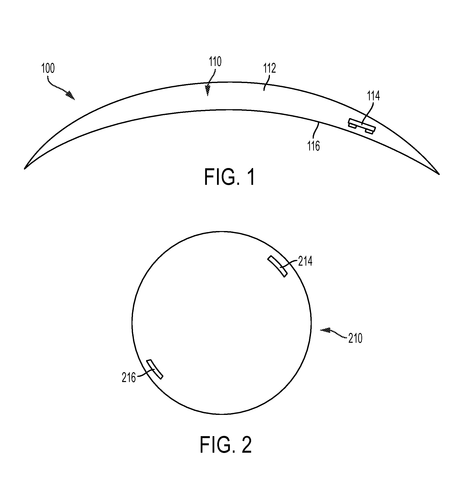
FIG. 1 shows a cut-away side view of an illustrative variation of a contact lens with a stimulator chip;
FIG. 2 shows a front view of an illustrative variation of a contact lens having a stimulator chip and a counterweight;
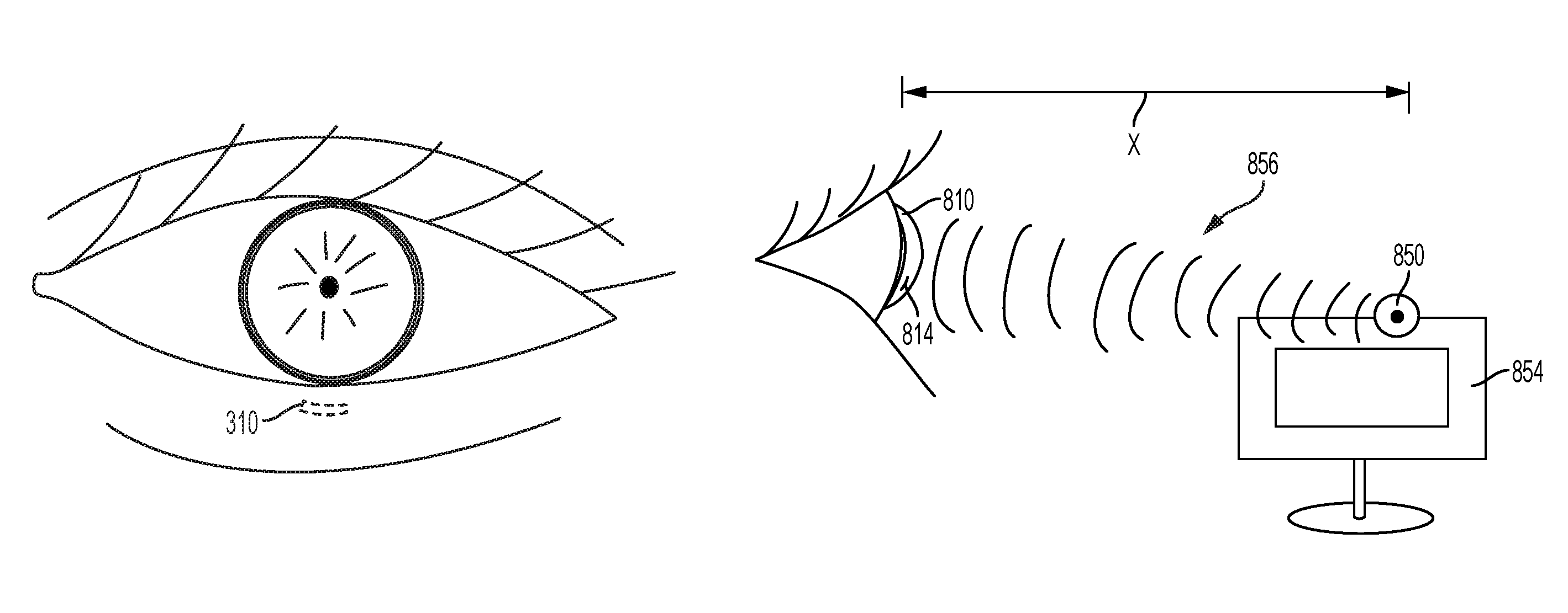
FIG. 3 shows an illustrative implantable device implanted in a position behind the lower eyelid;
FIG. 4 shows a block diagram illustrating a method of increasing tear production using a stimulator chip;
FIG. 5 shows an illustrative variation of a stimulator chip;
FIG. 6 shows an illustrative variation of the spectral response of a photodiode;
FIG. 7 shows an illustrative variation of an external power source comprising an optical modifier to produce non-collimated light;
FIG. 8 shows an illustrative variation of a system comprising a contact lens with a stimulator chip and a computer monitor-mounted external power source;
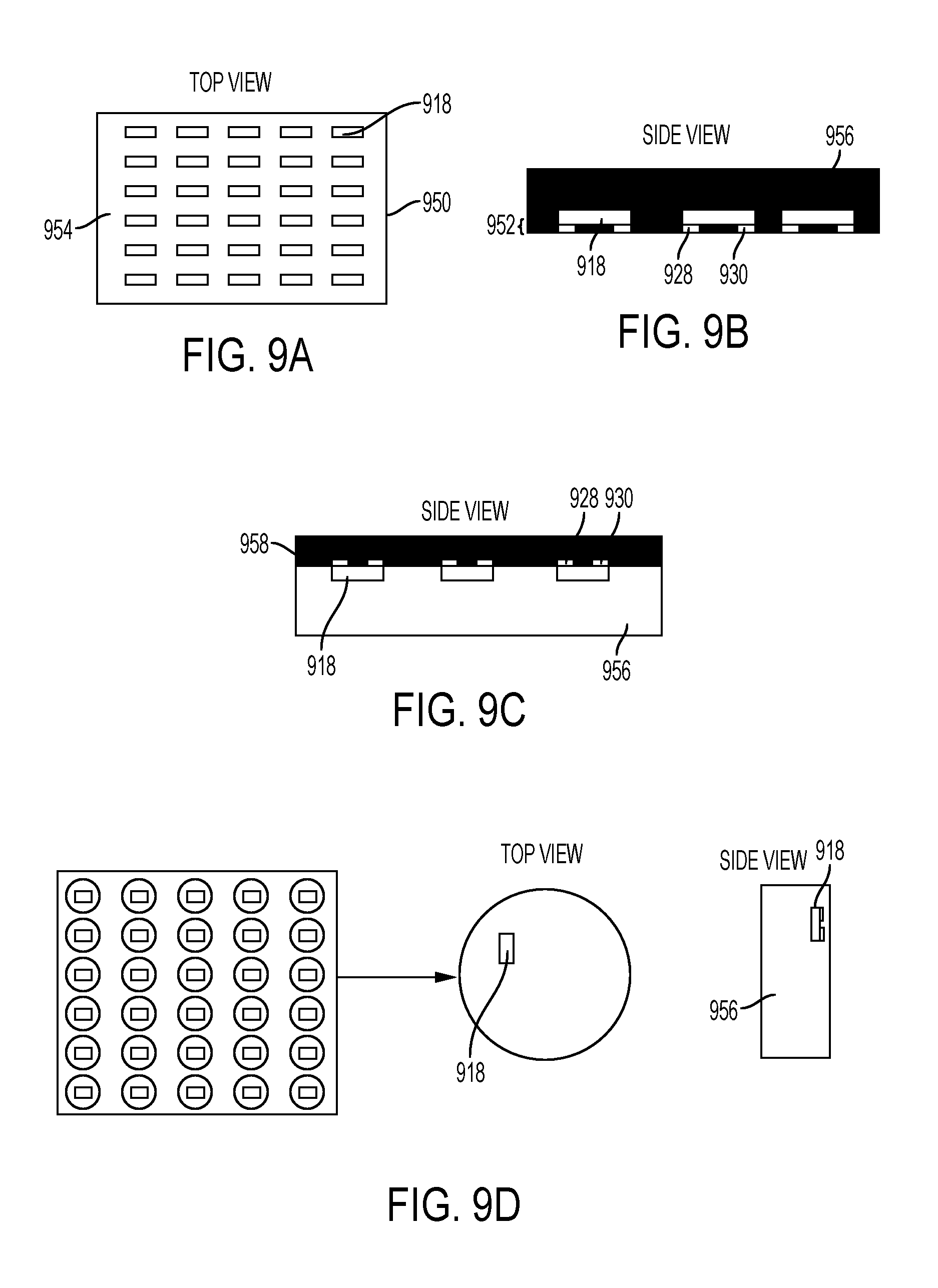
FIGS. 9A-9D show an illustrative variation of a method of manufacturing a contact lens using sheet casting;
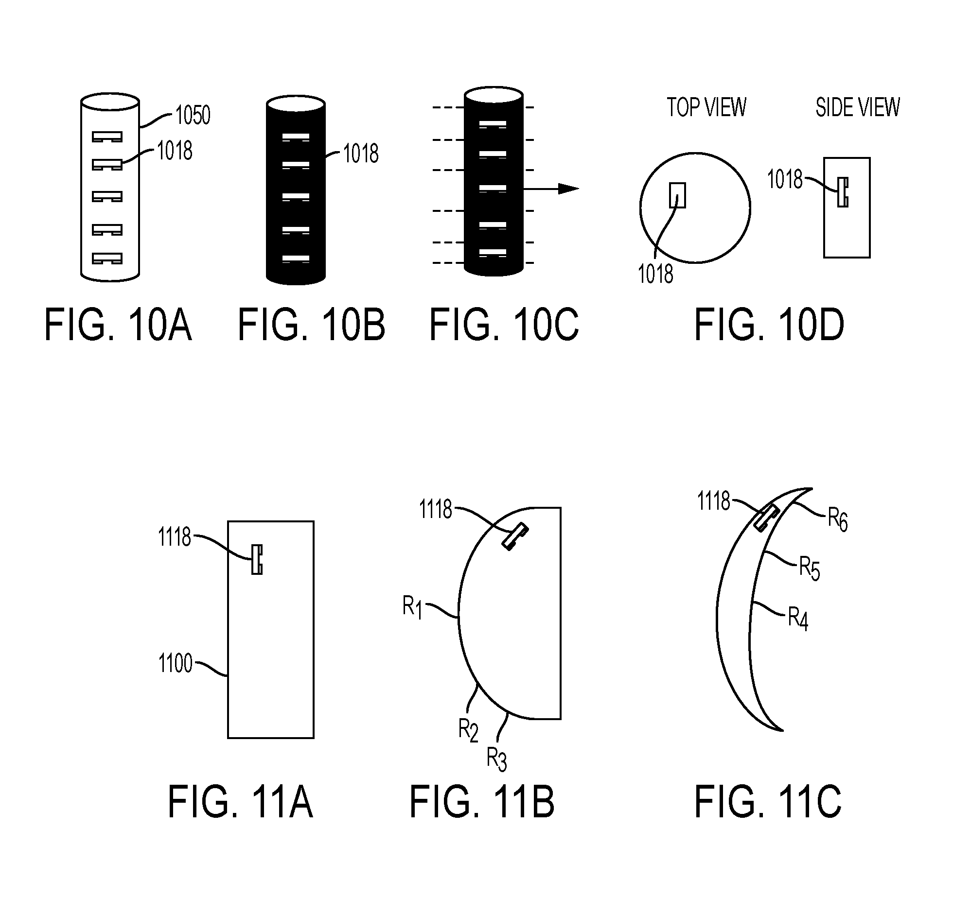
FIGS. 10A-10D show an illustrative variation of a method of manufacturing a contact lens using rod casting;
FIGS. 11A-11C show an illustrative variation of the shaping of a contact lens from button form to a meniscus lens using lathe cutting;
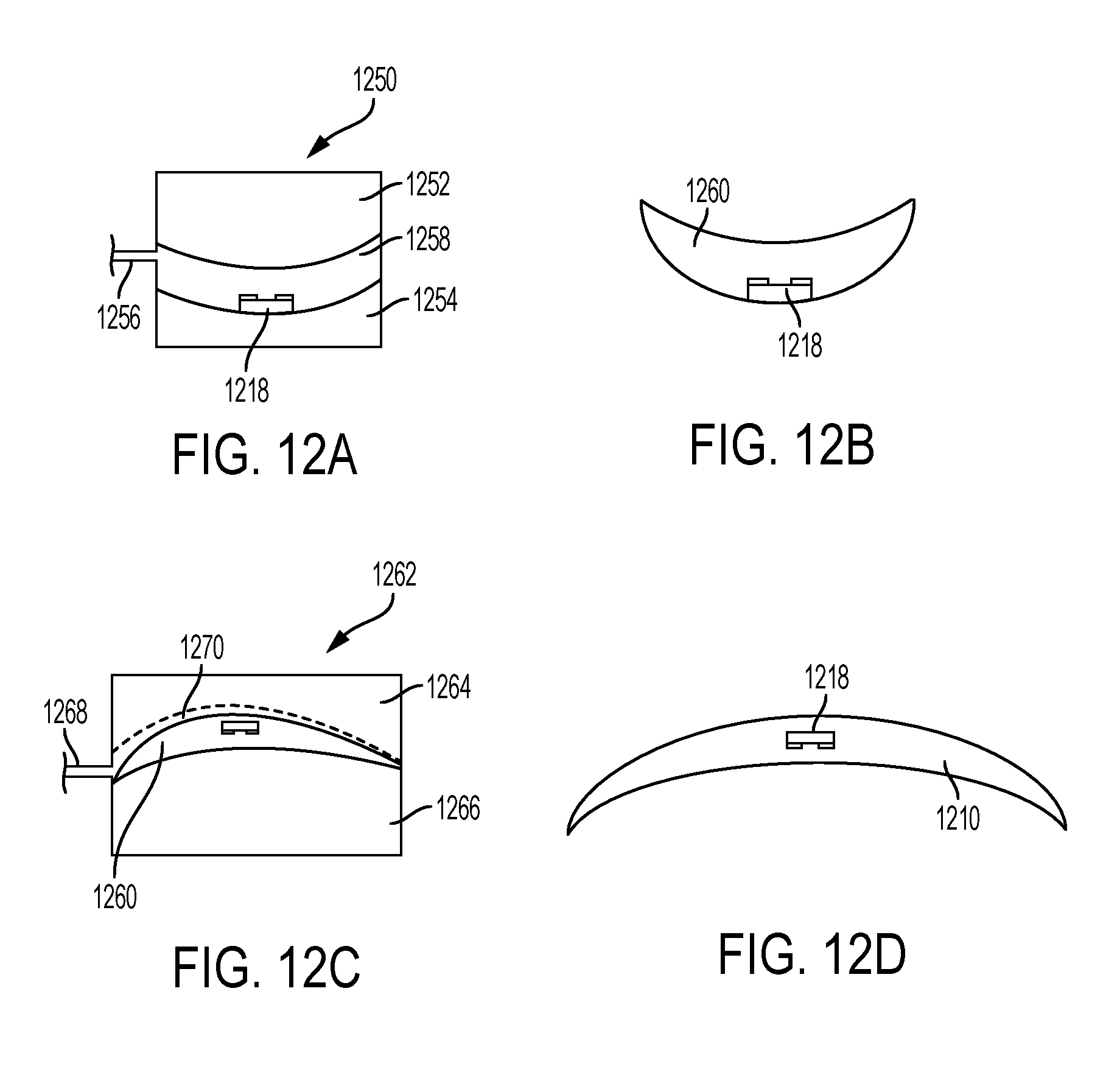
FIGS. 12A-12D show an illustrative variation of a method of manufacturing a contact lens using cast molding.
DETAILED DESCRIPTION
Described here are devices, systems, and methods for increasing tear production by stimulating the cornea, conjunctiva, and/or subconjunctiva. The device may be a contact lens or an implantable device, which may comprise a stimulator chip. The system may comprise the contact lens or implantable device and an external power source that may wirelessly transmit energy to the stimulator chip. The stimulator chip may convert the energy transmitted to an electric waveform, which may be delivered to a subject to electrically stimulate the cornea, conjunctiva, and/or subconjunctiva. This may in turn activate the reflex pathways and increase tear production.
The devices and systems for increasing tear production described here may be used in methods of treating dry eye caused by clinical and/or external factors. They may also be used in methods of reducing the symptoms of tired eye, increasing comfort for contact lens wearers, and extending the number of years a contact lens user can wear contacts. Also described are methods of manufacturing a contact lens, where the contact lens is configured to increase tear production by stimulating the cornea and/or conjunctiva.
Devices
The devices described here may be for placement on the cornea or for placement in the subconjunctiva of the eye. The devices may comprise a stimulator chip for electrically stimulating the cornea and/or conjunctiva to increase lacrimation in patients suffering from dry eye, tired eye, and other conditions.
Contact Lens
As shown in FIG. 1, device 100 is in the form a contact lens 110 for placement on the cornea/conjunctiva of the eye. The contact lens 110 has a lens body 112 made from a biomaterial. The biomaterial can be any optically clear and biologically compatible material. Classifications of acceptable biomaterials include, but are not limited to: hydrophilic acrylates, hydrophobic acrylates, rigid poly(methyl methacrylate) (PMMA), and polyurethanes. Also acceptable are hydrogel materials, including but not limited to: silicone hydrogels, silicone acrylates (SAs), fluoro-silicone acrylates, and various gas-permeable materials. The biomaterial may be ionic or non-ionic, and may have a high water content or low water content, such as ranging from about 30% to about 70%. In some variations, the contact lens may have a monoblock lens body. In other variations, the contact lens may have a hybrid lens body comprising a soft, pliable, optically clear center portion and a rigid perimeter portion made from a rigid gas permeable material.
The contact lens may be corrective having a power specific to the patient's needs. The contact lens may also be a toric, aspheric, multifocal, diffractive, scleral, or other type of corrective contact lens. Alternatively, the lens may be non-corrective/refractive (i.e., zero power) for patients who do not require corrective lenses but suffer from dry eye, tired eye, or other eye conditions. The lens also may be a bandage contact lens for protecting and healing the eye and increasing comfort for patients with damaged or compromised corneas.
Contact lens 110 comprises a stimulator chip 114 within the lens body 112. Stimulator chip 114 may be configured to convert wireless energy transmitted from an outside source to an electric waveform for electrically stimulating the cornea/conjunctiva. Stimulator chip 114 is embedded in the lens body 112 and is positioned close to the posterior surface 116 adjacent to the eye. Close proximity of the stimulator chip to the eye surface may allow for effective stimulation of the cornea and/or conjunctiva. Accordingly, in some variations, the stimulator chip may be within 5 microns, within 10 microns, or within 10-20 microns of the posterior surface of the lens. Larger stimulators may be positioned further from the posterior surface. In other variations, the stimulator chip may be within 50-100 microns of the posterior surface. In other variations, such as with hybrid lens bodies described herein, the stimulator chip may be mounted directly to the surface of the lens body. The stimulator chip may be located in a number of positions in the lens body, but it may be desirable for the stimulator chip to be located in the portion of the lens body that covers the iris of the eye when inserted, so as to avoid blocking the visual axis.
In some instances it may be desirable that the contact lens be rotationally unstable to allow repositioning of the stimulator chip when blinking. This may reduce accommodation and habituation to the stimulus. In one variation, a single stimulator chip embedded in the lens body is light enough in weight to not unbalance the contact lens or prevent repositioning. In another variation, shown in FIG. 2, a counterweight 216 is located approximately 180 degrees from a first stimulator chip 214 in order to balance the weight and prevent the first stimulator chip 214 from weighing down and inhibiting rotation of contact lens 210. The counterweight 216 may be, for example, another stimulator chip, but may also be an inactive chip or any suitable object having appropriate weight and size.
However, in other instances such rotational instability may be undesirable. For example, contact lenses used for astigmatism are generally toric lenses having different optical power and focal length in two perpendicular orientations. In these cases, rotation of the lens may negatively affect vision, and therefore may not be desirable. In some variations for addressing astigmatism, one, two, or more inactive chips, or other weights, may be placed in the lower portion of the lens body in order to help the lens find a specific orientation and minimize rotation.
Implantable Device
In another variation, the device may be in the form of an implantable device. The implantable device may comprise a stimulator chip that is implanted within the eye and may utilize reflex pathways to provide activation to the lacrimal gland to increase tear production, and in some cases to provide activation of the accessory glands.
The implantable device may in some instances be placed subconjunctivally. The implantable device may be implanted in any location in the subconjunctiva where the stimulator chip can be exposed to energy transmission from an external power source. As shown in FIG. 3, it may be preferable for an implantable device 310 to be implanted in the subconjunctiva behind an eyelid (e.g., the lower eyelid) to avoid cosmetic impact. In this location, the implantable device 310 may be hidden when the subject looks straight ahead or side-to-side, but may become exposed when looking up. In other variations, the implantable device may be implanted such that it is visible when the subject looks straight ahead or side-to-side. In these cases, the implant may be configured with a decorative shape and/or distinct color (e.g., a red heart), so as to appear to be eye jewelry.
Because the conjunctiva defines an open space between it and the cornea, an implantable device inserted in the subconjunctival space may tend to migrate. Accordingly, the implantable device may comprise one or more fixation features to secure it in place. In some variations, fixation features may include one or multiple feet extending from the device. The feet may measure approximately 50-100 microns in length. In some instances, the feet may be pushed into the sclera for anchorage. Fixation features may also include an angled pick or nail for holding the device in place, biocompatible glue for initial fixation, or any other suitable anchoring feature.
The stimulator chip may have a coating of a thickness that allows the stimulation device to be atraumatic and non-irritating when implanted in the eye, but close enough to the conjunctiva to stimulate the nerves therein. Close proximity of the stimulator chip to the eye surface may allow for effective stimulation of the cornea, conjunctiva, and/or subconjunctiva, while exposure may result in a foreign body sensation and irritation. Accordingly, in some variations, the stimulator chip may have a coating that is between about 5 microns and about 20 microns thick. In some variations, a coating may comprise a hydrogel in order to allow for ionic conduction.
Stimulator Chip
FIG. 4 shows a block diagram illustrating how tear production may be increased using a stimulator chip as described herein. Generally, an external power 401 source may transmit wireless energy to a stimulator chip 406. The stimulator chip 406 may then convert the energy to a stimulation signal E.sub.out comprising an electric waveform, which may be delivered to a subject for electrically stimulating the cornea/conjunctiva 408.
More specifically, the stimulator chip 406 may comprise a power receiver 403 and a signal conditioning unit 405. The power receiver 403 may be supplied with wireless energy from the external power source 401, and may convert the wireless energy to an electric signal E.sub.in. The signal conditioning unit 405 may receive the electric signal E.sub.in and then modify the electric signal E.sub.in into the desired electric output E.sub.out. The signal conditioning unit 405 may modify one or more of the signal's frequency, shape, and amplitude in any suitable manner (e.g., using resistive and capacitive elements, amplifiers). The electric output E.sub.out may be a desired stimulation signal and may be delivered via electrode contacts to the cornea/conjunctiva 408 to activate lacrimation. While the variation of the system described with respect to FIG. 4 comprises a signal conditioning unit to modify the signal to the desired electrical stimulus, it should appreciated that in some variations, the signal may additionally or alternatively be manipulated using the external power source (e.g., by pulsing the power source in a particular pattern). With photovoltaics, for the example, manipulation of the signal may be done entirely externally by manipulation of the external power source.
In some variations, the stimulator chip may comprise one or more photodiodes, which act as both the power receiver and the signal conditioning unit. FIG. 5 shows a variation of a stimulator chip comprising an integrated circuit 500. The integrated circuit may be formed by semiconductor fabrication techniques on any suitable substrate, such as but not limited to a silicon on insulator (SOI) substrate. FIG. 5 shows an SOI semiconductor substrate 512 having an insulator layer 514. Light pulsed at a higher irradiance than ambient light, depicted by multiple arrows, is transmitted to the stimulator chip, which comprises a photodiode in region 510. The stimulation signal (i.e., the electric output) produced may be delivered through vias 516 to electrode contacts 518, 520 for stimulating the ocular tissue. A stimulator chip comprising a single photodiode, as in FIG. 5, may produce a voltage of up to about 0.6 V, but it should be appreciated that if higher voltage is desired, multiple diodes may be formed in series on the substrate. The stimulator chip may also comprise more than two electrodes in some variations.
The electrodes may each have dimensions (e.g., a diameter) measuring between 50 microns and 150 microns, specifically between 75 microns and 125 microns, or more specifically approximately 100 microns. This may result in an area of neural activation of approximately 100 microns. The electrodes may be made from any suitable material, such as but not limited to platinum or iridium oxide films. The stimulator chip may have a length measuring between 0.5 mm and 1.5 mm, specifically between 0.75 mm and 1.25 mm, or more specifically approximately 1.0 mm. The stimulator chip may have a width measuring between 0.5 mm and 1.5 mm, specifically between 0.75 mm and 1.25 mm, or more specifically approximately 1.0 mm. The stimulator chip may have a thickness measuring between 5 microns and 100 microns, specifically between 10 microns and 50 microns, or more specifically approximately 20 microns. In some variations, the stimulator chip measures 1.0 mm.times.1.0 mm.times.20 microns. The above-mentioned dimensions are exemplary only, and are not limited to the ranges provided. The stimulation chip and components thereof may be actually be larger, as their s
References
D00000
D00001
D00002
D00003
D00004
D00005
D00006
D00007
D00008
XML
uspto.report is an independent third-party trademark research tool that is not affiliated, endorsed, or sponsored by the United States Patent and Trademark Office (USPTO) or any other governmental organization. The information provided by uspto.report is based on publicly available data at the time of writing and is intended for informational purposes only.
While we strive to provide accurate and up-to-date information, we do not guarantee the accuracy, completeness, reliability, or suitability of the information displayed on this site. The use of this site is at your own risk. Any reliance you place on such information is therefore strictly at your own risk.
All official trademark data, including owner information, should be verified by visiting the official USPTO website at www.uspto.gov. This site is not intended to replace professional legal advice and should not be used as a substitute for consulting with a legal professional who is knowledgeable about trademark law.