Optical image capturing system
Lai , et al.
U.S. patent number 10,606,033 [Application Number 15/298,986] was granted by the patent office on 2020-03-31 for optical image capturing system. This patent grant is currently assigned to ABILITY OPTO-ELECTRONICS TECHNOLOGY CO., LTD.. The grantee listed for this patent is ABILITY OPTO-ELECTRONICS TECHNOLOGY CO., LTD.. Invention is credited to Yeong-Ming Chang, Chien-Hsun Lai, Nai-Yuan Tang.


View All Diagrams
| United States Patent | 10,606,033 |
| Lai , et al. | March 31, 2020 |
Optical image capturing system
Abstract
An optical image capturing system includes, along the optical axis in order from an object side to an image side, a first lens, a second lens, a third lens, a fourth lens, a fifth lens, a sixth lens, and a seventh lens. At least one lens among the first to the sixth lenses has positive refractive force. The seventh lens can have negative refractive force, wherein both surfaces thereof are aspheric, and at least one surface thereof has an inflection point. The lenses in the optical image capturing system which have refractive power include the first to the seventh lenses. The optical image capturing system can increase aperture value and improve the imagining quality for use in compact cameras.
| Inventors: | Lai; Chien-Hsun (Taichung, TW), Tang; Nai-Yuan (Taichung, TW), Chang; Yeong-Ming (Taichung, TW) | ||||||||||
|---|---|---|---|---|---|---|---|---|---|---|---|
| Applicant: |
|
||||||||||
| Assignee: | ABILITY OPTO-ELECTRONICS TECHNOLOGY
CO., LTD. (Taichung, TW) |
||||||||||
| Family ID: | 59722108 | ||||||||||
| Appl. No.: | 15/298,986 | ||||||||||
| Filed: | October 20, 2016 |
Prior Publication Data
| Document Identifier | Publication Date | |
|---|---|---|
| US 20170254987 A1 | Sep 7, 2017 | |
Foreign Application Priority Data
| Mar 4, 2016 [TW] | 105106708 A | |||
| Current U.S. Class: | 1/1 |
| Current CPC Class: | G02B 5/208 (20130101); G02B 27/0025 (20130101); G02B 13/0045 (20130101); G02B 13/06 (20130101); G02B 9/64 (20130101); G02B 5/005 (20130101) |
| Current International Class: | G02B 13/00 (20060101); G02B 13/06 (20060101); G02B 5/00 (20060101); G02B 5/20 (20060101); G02B 9/64 (20060101); G02B 27/00 (20060101) |
| Field of Search: | ;359/755,708 |
References Cited [Referenced By]
U.S. Patent Documents
| 5493446 | February 1996 | Nakajima |
| 5946505 | August 1999 | Lee |
| 8903232 | December 2014 | Caldwell |
| 9488808 | November 2016 | Chen |
| 9690077 | June 2017 | Tang et al. |
| 9746644 | August 2017 | Tang et al. |
| 9851536 | December 2017 | Tang et al. |
| 9857561 | January 2018 | Tang et al. |
| 9857566 | January 2018 | Tang |
| 9874725 | January 2018 | Lai et al. |
| 9904014 | February 2018 | Chang et al. |
| 9958648 | May 2018 | Tang et al. |
| 9989739 | June 2018 | Lai |
| 10018807 | July 2018 | Tang et al. |
| 10078200 | September 2018 | Lai et al. |
| 2013/0286488 | October 2013 | Chae |
| 2014/0029115 | January 2014 | Liao |
| 2014/0043694 | February 2014 | Tsai |
| 2014/0204478 | July 2014 | Asami |
| 2015/0043091 | February 2015 | Bone |
| 2015/0185441 | July 2015 | Liao |
| 2016/0085055 | March 2016 | Asami |
| 2016/0109687 | April 2016 | Son |
| 2016/0116705 | April 2016 | Lee |
| 2017/0108662 | April 2017 | Lee |
| 2017/0293107 | October 2017 | Wang |
| 2018/0011296 | January 2018 | Lai et al. |
| 2018/0095245 | April 2018 | Kanzaki |
| 2018/0196226 | July 2018 | Chang et al. |
| 2018/0196234 | July 2018 | Chang et al. |
| 2018/0196239 | July 2018 | Chang et al. |
| 106483627 | Mar 2017 | CN | |||
| 106547072 | Mar 2017 | CN | |||
| 106556914 | Apr 2017 | CN | |||
| 106680968 | May 2017 | CN | |||
| 106707464 | May 2017 | CN | |||
| 106855653 | Jun 2017 | CN | |||
| 107132640 | Sep 2017 | CN | |||
| I414841 | Nov 2013 | TW | |||
| 201407187 | Feb 2014 | TW | |||
| 201510566 | Mar 2015 | TW | |||
| 201537209 | Oct 2015 | TW | |||
| 201600878 | Jan 2016 | TW | |||
Other References
|
Examination report for TW 105106708, dated Apr. 19, 2017, Total of 15 pages. cited by applicant . Search report for TW 105106708, dated Apr. 19, 2017, Total of 1 page. cited by applicant . English Abstract for TW201407187, Total of 1 page. cited by applicant . English Abstract for TW201510566, Total of 1 page. cited by applicant . English Abstract for TW201537209, Total of 1 page. cited by applicant . English Abstract for TW201600878, Total of 1 page. cited by applicant . English Abstract for TWI414841, Total of 1 page. cited by applicant . 1st Office Action for CN201611244224.2, dated Nov. 4, 2018, Total of 28 pages. cited by applicant . English Abstract for CN106483627, Total of 1 page. cited by applicant . English Abstract for CN106547072, Total of 1 page. cited by applicant . English Abstract for CN106556914, Total of 1 page. cited by applicant . English Abstract for CN106680968, Total of 1 page. cited by applicant . English Abstract for CN106707464, Total of 1 page. cited by applicant . English Abstract for CN106855653, Total of 1 page. cited by applicant . English Abstract for CN107132640, Total of 1 page. cited by applicant. |
Primary Examiner: Schwartz; Jordan M
Attorney, Agent or Firm: Wylie; R. Lynette Apex Juris, Pllc.
Claims
What is claimed is:
1. An optical image capturing system, in order along an optical axis from an object side to an image side, comprising: a first lens having negative refractive power; a second lens having refractive power; a third lens having refractive power; a fourth lens having refractive power; a fifth lens having refractive power; a sixth lens having refractive power; a seventh lens having refractive power; and an image plane; wherein the optical image capturing system has a total of the seven lenses with refractive power; the first lens is made of glass; at least five lenses among the second lens to the seventh lens is made of plastic; at least one lens among the second lens to the seventh lens has positive refractive power; each lens among the first lens to the seventh lens has an object-side surface, which faces the object side, and an image-side surface, which faces the image side; wherein the optical image capturing system satisfies: 1.0.ltoreq.f/HEP.ltoreq.10.0; 1.2.ltoreq.IN12/f.ltoreq.5.0; 0 deg<HAF.ltoreq.150 deg; and 0.9.ltoreq.2(ARE/HEP).ltoreq.1.5; where f is a focal length of the optical image capturing system; HEP is an entrance pupil diameter of the optical image capturing system; HAF is a half of a maximum field angle of the optical image capturing system; for any surface of any lens, ARE is a profile curve length measured from a start point where the optical axis passes therethrough, along a surface profile thereof, and finally to a coordinate point of a perpendicular distance where is a half of the entrance pupil diameter away from the optical axis; IN12 is a distance on the optical axis between the first lens and the second lens; wherein the optical image capturing system further satisfies: 0<IN67/f.ltoreq.0.8; where IN67 is a distance on the optical axis between the sixth lens and the seventh lens.
2. The optical image capturing system of claim 1, wherein each two neighboring lenses among the first to the seventh lenses are separated by air.
3. The optical image capturing system of claim 1, wherein the optical image capturing system further satisfies: 0.9.ltoreq.ARS/EHD.ltoreq.2.0; where, for any surface of any lens, EHD is a maximum effective half diameter thereof, ARS is a profile curve length measured from a start point where the optical axis passes therethrough, along a surface profile thereof, and finally to an end point of the maximum effective half diameter thereof.
4. The optical image capturing system of claim 1, wherein the image plane is either flat or curved.
5. The optical image capturing system of claim 1, wherein at least one lens among the first lens, the second lens, the third lens, the fourth lens, the fifth lens, the sixth lens, and the seventh lens is configured to filter out light of wavelengths shorter than 500 nm.
6. The optical image capturing system of claim 1, wherein the optical image capturing system further satisfies: 0.1.ltoreq.(TP7+IN67)/TP6.ltoreq.10; where IN67 is a distance on the optical axis between the sixth lens and the seventh lens; TP6 is a thickness of the sixth lens on the optical axis; TP7 is a thickness of the seventh lens on the optical axis.
7. The optical image capturing system of claim 1, wherein the optical image capturing system further satisfies: 0.1.ltoreq.(TP1+IN12)/TP2.ltoreq.10; where IN12 is a distance on the optical axis between the first lens and the second lens; TP1 is a thickness of the first lens on the optical axis; TP2 is a thickness of the second lens on the optical axis.
8. The optical image capturing system of claim 1, wherein the optical image capturing system further satisfies: 0<TP4/(IN34+TP4+IN45)<1; where IN34 is a distance on the optical axis between the third lens and the fourth lens; IN45 is a distance on the optical axis between the fourth lens and the fifth lens; TP4 is a thickness of the fourth lens on the optical axis.
Description
BACKGROUND OF THE INVENTION
1. Technical Field
The present invention relates generally to an optical system, and more particularly to a compact optical image capturing system for an electronic device.
2. Description of Related Art
In recent years, with the rise of portable electronic devices having camera functionalities, the demand for an optical image capturing system is raised gradually. The image sensing device of the ordinary photographing camera is commonly selected from charge coupled device (CCD) or complementary metal-oxide semiconductor sensor (CMOS Sensor). In addition, as advanced semiconductor manufacturing technology enables the minimization of the pixel size of the image sensing device, the development of the optical image capturing system towards the field of high pixels. Therefore, the requirement for high imaging quality is rapidly raised.
The conventional optical system of the portable electronic device usually has five or six lenses. However, the optical system is asked to take pictures in a dark environment, in other words, the optical system is asked to have a large aperture. The conventional optical system provides high optical performance as required.
It is an important issue to increase the quantity of light entering the lens. In addition, the modern lens is also asked to have several characters, including high image quality.
BRIEF SUMMARY OF THE INVENTION
The aspect of embodiment of the present disclosure directs to an optical image capturing system and an optical image capturing lens which use combination of refractive powers, convex and concave surfaces of seven-piece optical lenses (the convex or concave surface in the disclosure denotes the geometrical shape of an image-side surface or an object-side surface of each lens on an optical axis) to increase the quantity of incoming light of the optical image capturing system, and to improve imaging quality for image formation, so as to be applied to minimized electronic products.
The term and its definition to the lens parameter in the embodiment of the present are shown as below for further reference.
The lens parameter related to a length or a height in the lens:
A maximum height for image formation of the optical image capturing system is denoted by HOI. A height of the optical image capturing system is denoted by HOS. A distance from the object-side surface of the first lens to the image-side surface of the seventh lens is denoted by InTL. A distance from the first lens to the second lens is denoted by IN12 (instance). A central thickness of the first lens of the optical image capturing system on the optical axis is denoted by TP1 (instance).
The lens parameter related to a material in the lens:
An Abbe number of the first lens in the optical image capturing system is denoted by NA1 (instance). A refractive index of the first lens is denoted by Nd1 (instance).
The lens parameter related to a view angle in the lens:
A view angle is denoted by AF. Half of the view angle is denoted by HAF. A major light angle is denoted by MRA.
The lens parameter related to exit/entrance pupil in the lens:
An entrance pupil diameter of the optical image capturing system is denoted by HEP. For any surface of any lens, a maximum effective half diameter (EHD) is a perpendicular distance between an optical axis and a crossing point on the surface where the incident light with a maximum viewing angle of the system passing the very edge of the entrance pupil. For example, the maximum effective half diameter of the object-side surface of the first lens is denoted by EHD11, the maximum effective half diameter of the image-side surface of the first lens is denoted by EHD12, the maximum effective half diameter of the object-side surface of the second lens is denoted by EHD21, the maximum effective half diameter of the image-side surface of the second lens is denoted by EHD22, and so on.
The lens parameter related to an arc length of the shape of a surface and a surface profile:
For any surface of any lens, a profile curve length of the maximum effective half diameter is, by definition, measured from a start point where the optical axis of the belonging optical image capturing system passes through the surface of the lens, along a surface profile of the lens, and finally to an end point of the maximum effective half diameter thereof. In other words, the curve length between the aforementioned start and end points is the profile curve length of the maximum effective half diameter, which is denoted by ARS. For example, the profile curve length of the maximum effective half diameter of the object-side surface of the first lens is denoted by ARS11, the profile curve length of the maximum effective half diameter of the image-side surface of the first lens is denoted by ARS12, the profile curve length of the maximum effective half diameter of the object-side surface of the second lens is denoted by ARS21, the profile curve length of the maximum effective half diameter of the image-side surface of the second lens is denoted by ARS22, and so on.
For any surface of any lens, a profile curve length of a half of the entrance pupil diameter (HEP) is, by definition, measured from a start point where the optical axis of the belonging optical image capturing system passes through the surface of the lens, along a surface profile of the lens, and finally to a coordinate point of a perpendicular distance where is a half of the entrance pupil diameter away from the optical axis. In other words, the curve length between the aforementioned stat point and the coordinate point is the profile curve length of a half of the entrance pupil diameter (HEP), and is denoted by ARE. For example, the profile curve length of a half of the entrance pupil diameter (HEP) of the object-side surface of the first lens is denoted by ARE11, the profile curve length of a half of the entrance pupil diameter (HEP) of the image-side surface of the first lens is denoted by ARE12, the profile curve length of a half of the entrance pupil diameter (HEP) of the object-side surface of the second lens is denoted by ARE21, the profile curve length of a half of the entrance pupil diameter (HEP) of the image-side surface of the second lens is denoted by ARE22, and so on.
The lens parameter related to a depth of the lens shape:
A distance in parallel with the optical axis from a point where the optical axis passes through to an end point of the maximum effective semi diameter on the object-side surface of the seventh lens is denoted by InRS71 (the depth of the maximum effective semi diameter). A distance in parallel with the optical axis from a point where the optical axis passes through to an end point of the maximum effective semi diameter on the image-side surface of the seventh lens is denoted by InRS72 (the depth of the maximum effective semi diameter). The depth of the maximum effective semi diameter (sinkage) on the object-side surface or the image-side surface of any other lens is denoted in the same manner.
The lens parameter related to the lens shape:
A critical point C is a tangent point on a surface of a specific lens, and the tangent point is tangent to a plane perpendicular to the optical axis and the tangent point cannot be a crossover point on the optical axis. Following the above description, a distance perpendicular to the optical axis between a critical point C51 on the object-side surface of the fifth lens and the optical axis is HVT51 (instance), and a distance perpendicular to the optical axis between a critical point C52 on the image-side surface of the fifth lens and the optical axis is HVT52 (instance). A distance perpendicular to the optical axis between a critical point C61 on the object-side surface of the sixth lens and the optical axis is HVT61 (instance), and a distance perpendicular to the optical axis between a critical point C62 on the image-side surface of the sixth lens and the optical axis is HVT62 (instance). A distance perpendicular to the optical axis between a critical point on the object-side or image-side surface of other lenses, such as the seventh lens, and the optical axis is denoted in the same manner.
The object-side surface of the seventh lens has one inflection point IF711 which is nearest to the optical axis, and the sinkage value of the inflection point IF711 is denoted by SGI711 (instance). A distance perpendicular to the optical axis between the inflection point IF711 and the optical axis is HIF711 (instance). The image-side surface of the seventh lens has one inflection point IF721 which is nearest to the optical axis, and the sinkage value of the inflection point IF721 is denoted by SGI721 (instance). A distance perpendicular to the optical axis between the inflection point IF721 and the optical axis is HIF721 (instance).
The object-side surface of the seventh lens has one inflection point IF712 which is the second nearest to the optical axis, and the sinkage value of the inflection point IF712 is denoted by SGI712 (instance). A distance perpendicular to the optical axis between the inflection point IF712 and the optical axis is HIF712 (instance). The image-side surface of the seventh lens has one inflection point IF722 which is the second nearest to the optical axis, and the sinkage value of the inflection point IF722 is denoted by SGI722 (instance). A distance perpendicular to the optical axis between the inflection point IF722 and the optical axis is HIF722 (instance).
The object-side surface of the seventh lens has one inflection point IF713 which is the third nearest to the optical axis, and the sinkage value of the inflection point IF713 is denoted by SGI713 (instance). A distance perpendicular to the optical axis between the inflection point IF713 and the optical axis is HIF713 (instance). The image-side surface of the seventh lens has one inflection point IF723 which is the third nearest to the optical axis, and the sinkage value of the inflection point IF723 is denoted by SGI723 (instance). A distance perpendicular to the optical axis between the inflection point IF723 and the optical axis is HIF723 (instance).
The object-side surface of the seventh lens has one inflection point IF714 which is the fourth nearest to the optical axis, and the sinkage value of the inflection point IF714 is denoted by SGI714 (instance). A distance perpendicular to the optical axis between the inflection point IF714 and the optical axis is HIF714 (instance). The image-side surface of the seventh lens has one inflection point IF724 which is the fourth nearest to the optical axis, and the sinkage value of the inflection point IF724 is denoted by SGI724 (instance). A distance perpendicular to the optical axis between the inflection point IF724 and the optical axis is HIF724 (instance).
An inflection point, a distance perpendicular to the optical axis between the inflection point and the optical axis, and a sinkage value thereof on the object-side surface or image-side surface of other lenses is denoted in the same manner.
The lens parameter related to an aberration:
Optical distortion for image formation in the optical image capturing system is denoted by ODT. TV distortion for image formation in the optical image capturing system is denoted by TDT. Further, the range of the aberration offset for the view of image formation may be limited to 50%-100% field. An offset of the spherical aberration is denoted by DFS. An offset of the coma aberration is denoted by DFC.
Transverse aberration on an edge of an aperture is denoted by STA, which stands for STOP transverse aberration, and is used to evaluate the performance of one specific optical image capturing system. The transverse aberration of light in any field of view can be calculated with a tangential fan or a sagittal fan. More specifically, the transverse aberration caused when the longest operation wavelength (e.g., 650 nm) and the shortest operation wavelength (e.g., 470 nm) pass through the edge of the aperture can be used as the reference for evaluating performance. The coordinate directions of the aforementioned tangential fan can be further divided into a positive direction (upper light) and a negative direction (lower light). The longest operation wavelength which passes through the edge of the aperture has an imaging position on the image plane in a particular field of view, and the reference wavelength of the mail light (e.g., 555 nm) has another imaging position on the image plane in the same field of view. The transverse aberration caused when the longest operation wavelength passes through the edge of the aperture is defined as a distance between these two imaging positions. Similarly, the shortest operation wavelength which passes through the edge of the aperture has an imaging position on the image plane in a particular field of view, and the transverse aberration caused when the shortest operation wavelength passes through the edge of the aperture is defined as a distance between the imaging position of the shortest operation wavelength and the imaging position of the reference wavelength. The performance of the optical image capturing system can be considered excellent if the transverse aberrations of the shortest and the longest operation wavelength which pass through the edge of the aperture and image on the image plane in 0.7 field of view (i.e., 0.7 times the height for image formation HOI) are both less than 100 .mu.m. Furthermore, for a stricter evaluation, the performance cannot be considered excellent unless the transverse aberrations of the shortest and the longest operation wavelength which pass through the edge of the aperture and image on the image plane in 0.7 field of view are both less than 80 .mu.m.
The optical image capturing system has a maximum image height HOI on the image plane vertical to the optical axis. A transverse aberration at 0.7 HOI in the positive direction of the tangential fan after the longest operation wavelength of visible light passing through the edge of the aperture is denoted by PLTA; a transverse aberration at 0.7 HOI in the positive direction of the tangential fan after the shortest operation wavelength of visible light passing through the edge of the aperture is denoted by PSTA; a transverse aberration at 0.7 HOI in the negative direction of the tangential fan after the longest operation wavelength of visible light passing through the edge of the aperture is denoted by NLTA; a transverse aberration at 0.7 HOI in the negative direction of the tangential fan after the shortest operation wavelength of visible light passing through the edge of the aperture is denoted by NSTA; a transverse aberration at 0.7 HOI of the sagittal fan after the longest operation wavelength of visible light passing through the edge of the aperture is denoted by SLTA; a transverse aberration at 0.7 HOI of the sagittal fan after the shortest operation wavelength of visible light passing through the edge of the aperture is denoted by SSTA.
The present invention provides an optical image capturing system capable of focusing for both visible light and infrared light (i.e., dual mode) with certain performance, in which the seventh lens is provided with an inflection point at the object-side surface or at the image-side surface to adjust the incident angle of each view field and modify the ODT and the TDT. In addition, the surfaces of the seventh lens are capable of modifying the optical path to improve the imagining quality.
The optical image capturing system of the present invention includes a first lens, a second lens, a third lens, a fourth lens, a fifth lens, a sixth lens, a seventh lens, and an image plane in order along an optical axis from an object side to an image side. At least one lens among the first to the seventh lens is made of glass. At least four lenses among the first to the seventh lens are made of plastic. The first lens has refractive power. The optical image capturing system satisfies: 1.0.ltoreq.f/HEP.ltoreq.10.0; 0 deg.ltoreq.HAF.ltoreq.150 deg; and 0.9.ltoreq.2(ARE/HEP).ltoreq.1.5;
where f1, f2, f3, f4, f5, f6, and f7 are respectively the focal lengths of the first lens to the seventh lens; f is a focal length of the optical image capturing system; HEP is an entrance pupil diameter of the optical image capturing system; HOS is a distance in parallel with the optical axis between an object-side surface, which face the object side, of the first lens and the image plane; InTL is a distance between the object-side surface of the first lens and the image-side surface of the seventh lens on the optical axis; HAF is a half of the maximum field angle; ARE is a profile curve length measured from a start point where the optical axis of the belonging optical image capturing system passes through the surface of the lens, along a surface profile of the lens, and finally to a coordinate point of a perpendicular distance where is a half of the entrance pupil diameter away from the optical axis.
The present invention further provides an optical image capturing system, including a first lens, a second lens, a third lens, a fourth lens, a fifth lens, a sixth lens, a seventh lens, and an image plane in order along an optical axis from an object side to an image side. The first lens is made of glass, while at least five lenses among the second lens to the seventh lens is made of plastic. The first lens has refractive power, and an object-side surface thereof near the optical axis could be convex. The second lens has refractive power. The third lens has refractive power. The fourth lens has refractive power. The fifth lens has refractive power. The sixth lens has refractive power. The seventh lens has refractive power, wherein the object-side surface and the image-side surface thereof are both aspheric surfaces. At least one lens among the second lens to the seventh lens has positive refractive power. The optical image capturing system satisfies: 1.0.ltoreq.f/HEP.ltoreq.10.0; 0<InTL/HOS<0.9; 0 deg<HAF.ltoreq.150 deg; and 0.9.ltoreq.2(ARE/HEP).ltoreq.1.5;
where f1, f2, f3, f4, f5, f6, and f7 are respectively the focal lengths of the first lens to the seventh lens; f is a focal length of the optical image capturing system; HEP is an entrance pupil diameter of the optical image capturing system; HOS is a distance in parallel with the optical axis between an object-side surface, which face the object side, of the first lens and the image plane; InTL is a distance between the object-side surface of the first lens and the image-side surface of the seventh lens on the optical axis; HAF is a half of the maximum field angle; ARE is a profile curve length measured from a start point where the optical axis of the belonging optical image capturing system passes through the surface of the lens, along a surface profile of the lens, and finally to a coordinate point of a perpendicular distance where is a half of the entrance pupil diameter away from the optical axis.
The present invention further provides an optical image capturing system, including a first lens, a second lens, a third lens, a fourth lens, a fifth lens, a sixth lens, a seventh lens, and an image plane, in order along an optical axis from an object side to an image side. The number of the lenses having refractive power in the optical image capturing system is seven. Five lenses among the first to the seventh lenses are made of plastic, while the other two lenses are made of glass. The first lens has negative refractive power, and the second lens has refractive power. The third lens has refractive power. The fourth lens has refractive power. The fifth lens has refractive power. The sixth lens has refractive power. The seventh lens has refractive power. The optical image capturing system satisfies: 1.0.ltoreq.f/HEP.ltoreq.6.0; 0<InTL/HOS<0.9; 0 deg<HAF.ltoreq.150 deg; and 0.9.ltoreq.2(ARE/HEP).ltoreq.1.5;
where f1, f2, f3, f4, f5, f6, and f7 are respectively the focal lengths of the first lens to the seventh lens; f is a focal length of the optical image capturing system; HEP is an entrance pupil diameter of the optical image capturing system; HOS is a distance in parallel with the optical axis between an object-side surface, which face the object side, of the first lens and the image plane; InTL is a distance between the object-side surface of the first lens and the image-side surface of the seventh lens on the optical axis; HAF is a half of the maximum field angle; ARE is a profile curve length measured from a start point where the optical axis of the belonging optical image capturing system passes through the surface of the lens, along a surface profile of the lens, and finally to a coordinate point of a perpendicular distance where is a half of the entrance pupil diameter away from the optical axis.
For any surface of any lens, the profile curve length within the effective half diameter affects the ability of the surface to correct aberration and differences between optical paths of light in different fields of view. With longer profile curve length, the ability to correct aberration is better. However, the difficulty of manufacturing increases as well. Therefore, the profile curve length within the effective half diameter of any surface of any lens has to be controlled. The ratio between the profile curve length (ARS) within the effective half diameter of one surface and the thickness (TP) of the lens, which the surface belonged to, on the optical axis (i.e., ARS/TP) has to be particularly controlled. For example, the profile curve length of the maximum effective half diameter of the object-side surface of the first lens is denoted by ARS11, the thickness of the first lens on the optical axis is TP1, and the ratio between these two parameters is ARS11/TP1; the profile curve length of the maximum effective half diameter of the image-side surface of the first lens is denoted by ARS12, and the ratio between ARS12 and TP1 is ARS12/TP1. The profile curve length of the maximum effective half diameter of the object-side surface of the second lens is denoted by ARS21, the thickness of the second lens on the optical axis is TP2, and the ratio between these two parameters is ARS21/TP2; the profile curve length of the maximum effective half diameter of the image-side surface of the second lens is denoted by ARS22, and the ratio between ARS22 and TP2 is ARS22/TP2. For any surface of other lenses in the optical image capturing system, the ratio between the profile curve length of the maximum effective half diameter thereof and the thickness of the lens which the surface belonged to is denoted in the same manner.
For any surface of any lens, the profile curve length within a half of the entrance pupil diameter (HEP) affects the ability of the surface to correct aberration and differences between optical paths of light in different fields of view. With longer profile curve length, the ability to correct aberration is better. However, the difficulty of manufacturing increases as well. Therefore, the profile curve length within a half of the entrance pupil diameter (HEP) of any surface of any lens has to be controlled. The ratio between the profile curve length (ARE) within a half of the entrance pupil diameter (HEP) of one surface and the thickness (TP) of the lens, which the surface belonged to, on the optical axis (i.e., ARE/TP) has to be particularly controlled. For example, the profile curve length of a half of the entrance pupil diameter (HEP) of the object-side surface of the first lens is denoted by ARE11, the thickness of the first lens on the optical axis is TP1, and the ratio between these two parameters is ARE11/TP1; the profile curve length of a half of the entrance pupil diameter (HEP) of the image-side surface of the first lens is denoted by ARE12, and the ratio between ARE12 and TP1 is ARE12/TP1. The profile curve length of a half of the entrance pupil diameter (HEP) of the object-side surface of the second lens is denoted by ARE21, the thickness of the second lens on the optical axis is TP2, and the ratio between these two parameters is ARE21/TP2; the profile curve length of a half of the entrance pupil diameter (HEP) of the image-side surface of the second lens is denoted by ARE22, and the ratio between ARE22 and TP2 is ARE22/TP2. For any surface of other lenses in the optical image capturing system, the ratio between the profile curve length of a half of the entrance pupil diameter (HEP) thereof and the thickness of the lens which the surface belonged to is denoted in the same manner.
In an embodiment, a height of the optical image capturing system (HOS) can be reduced if |f1|>|f7|.
In an embodiment, when |f2|+|f3|+|f4|+|f5|+|f6| and |f1|+|f7| of the lenses satisfy the aforementioned conditions, at least one lens among the second to the sixth lenses could have weak positive refractive power or weak negative refractive power. Herein the weak refractive power means the absolute value of the focal length of one specific lens is greater than 10. When at least one lens among the second to the sixth lenses has weak positive refractive power, it may share the positive refractive power of the first lens, and on the contrary, when at least one lens among the second to the sixth lenses has weak negative refractive power, it may fine turn and correct the aberration of the system.
In an embodiment, the seventh lens could have negative refractive power, and an image-side surface thereof is concave, it may reduce back focal length and size. Besides, the seventh lens can have at least an inflection point on at least a surface thereof, which may reduce an incident angle of the light of an off-axis field of view and correct the aberration of the off-axis field of view.
BRIEF DESCRIPTION OF THE SEVERAL VIEWS OF THE DRAWINGS
The present invention will be best understood by referring to the following detailed description of some illustrative embodiments in conjunction with the accompanying drawings, in which
FIG. 1A is a schematic diagram of a first embodiment of the present invention;
FIG. 1B shows curve diagrams of longitudinal spherical aberration, astigmatic field, and optical distortion of the optical image capturing system in the order from left to right of the first embodiment of the present application;
FIG. 1C shows a tangential fan and a sagittal fan of the optical image capturing system of the first embodiment of the present application, and a transverse aberration diagram at 0.7 field of view when a longest operation wavelength and a shortest operation wavelength pass through an edge of an aperture;
FIG. 2A is a schematic diagram of a second embodiment of the present invention;
FIG. 2B shows curve diagrams of longitudinal spherical aberration, astigmatic field, and optical distortion of the optical image capturing system in the order from left to right of the second embodiment of the present application;
FIG. 2C shows a tangential fan and a sagittal fan of the optical image capturing system of the second embodiment of the present application, and a transverse aberration diagram at 0.7 field of view when a longest operation wavelength and a shortest operation wavelength pass through an edge of an aperture;
FIG. 3A is a schematic diagram of a third embodiment of the present invention;
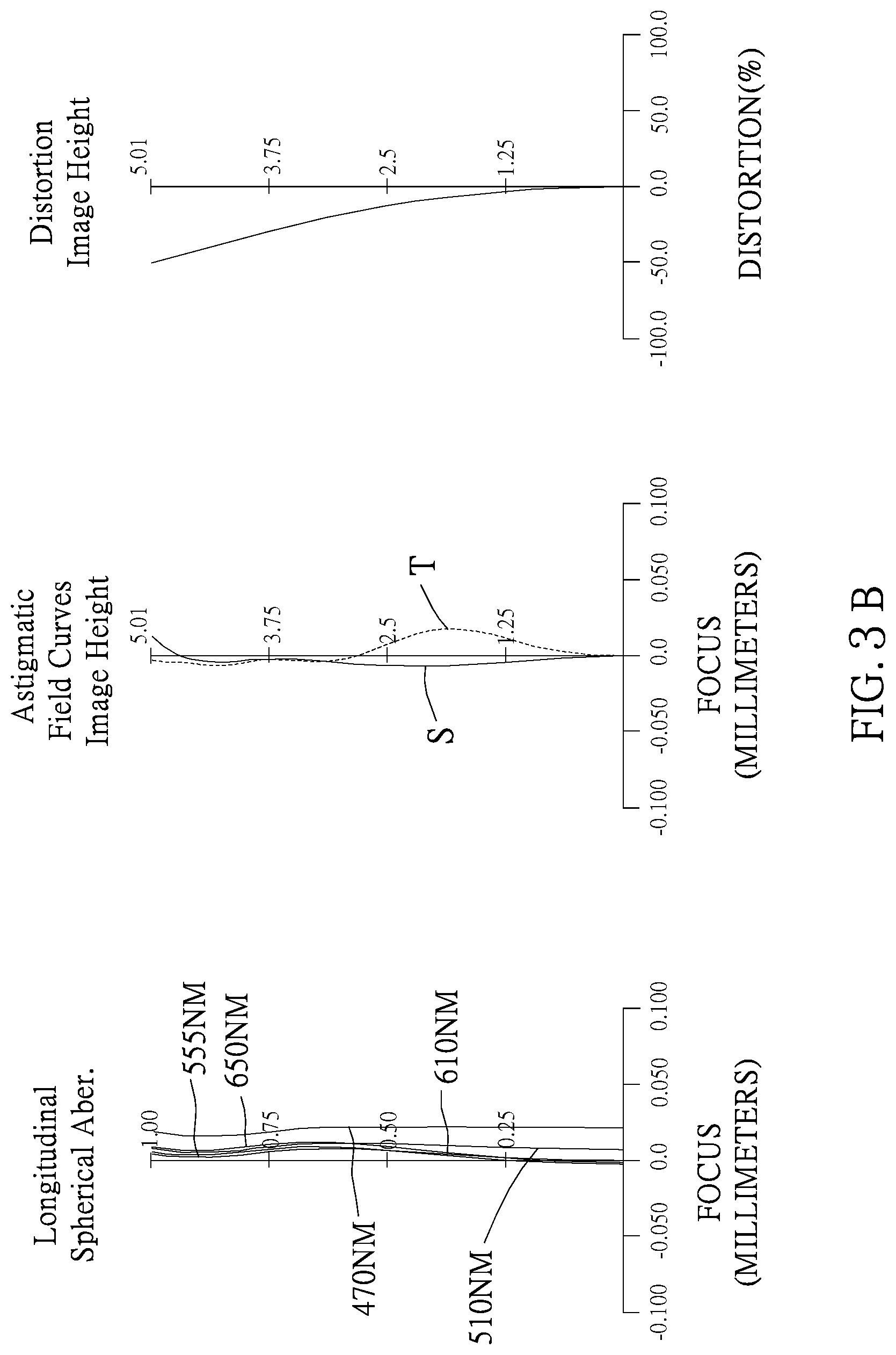
FIG. 3B shows curve diagrams of longitudinal spherical aberration, astigmatic field, and optical distortion of the optical image capturing system in the order from left to right of the third embodiment of the present application;
FIG. 3C shows a tangential fan and a sagittal fan of the optical image capturing system of the third embodiment of the present application, and a transverse aberration diagram at 0.7 field of view when a longest operation wavelength and a shortest operation wavelength pass through an edge of an aperture;
FIG. 4A is a schematic diagram of a fourth embodiment of the present invention;
FIG. 4B shows curve diagrams of longitudinal spherical aberration, astigmatic field, and optical distortion of the optical image capturing system in the order from left to right of the fourth embodiment of the present application;
FIG. 4C shows a tangential fan and a sagittal fan of the optical image capturing system of the fourth embodiment of the present application, and a transverse aberration diagram at 0.7 field of view when a longest operation wavelength and a shortest operation wavelength pass through an edge of an aperture;
FIG. 5A is a schematic diagram of a fifth embodiment of the present invention;
FIG. 5B shows curve diagrams of longitudinal spherical aberration, astigmatic field, and optical distortion of the optical image capturing system in the order from left to right of the fifth embodiment of the present application;
FIG. 5C shows a tangential fan and a sagittal fan of the optical image capturing system of the fifth embodiment of the present application, and a transverse aberration diagram at 0.7 field of view when a longest operation wavelength and a shortest operation wavelength pass through an edge of an aperture;
FIG. 6A is a schematic diagram of a sixth embodiment of the present invention;
FIG. 6B shows curve diagrams of longitudinal spherical aberration, astigmatic field, and optical distortion of the optical image capturing system in the order from left to right of the sixth embodiment of the present application;
FIG. 6C shows a tangential fan and a sagittal fan of the optical image capturing system of the sixth embodiment of the present application, and a transverse aberration diagram at 0.7 field of view when a longest operation wavelength and a shortest operation wavelength pass through an edge of an aperture;
FIG. 7A is a schematic diagram of a seventh embodiment of the present invention;
FIG. 7B shows curve diagrams of longitudinal spherical aberration, astigmatic field, and optical distortion of the optical image capturing system in the order from left to right of the seventh embodiment of the present application;
FIG. 7C shows a tangential fan and a sagittal fan of the optical image capturing system of the seventh embodiment of the present application, and a transverse aberration diagram at 0.7 field of view when a longest operation wavelength and a shortest operation wavelength pass through an edge of an aperture;
FIG. 8A is a schematic diagram of a eighth embodiment of the present invention;
FIG. 8B shows curve diagrams of longitudinal spherical aberration, astigmatic field, and optical distortion of the optical image capturing system in the order from left to right of the eighth embodiment of the present application; and
FIG. 8C shows a tangential fan and a sagittal fan of the optical image capturing system of the eighth embodiment of the present application, and a transverse aberration diagram at 0.7 field of view when a longest operation wavelength and a shortest operation wavelength pass through an edge of an aperture.
DETAILED DESCRIPTION OF THE INVENTION
An optical image capturing system of the present invention includes a first lens, a second lens, a third lens, a fourth lens, a fifth lens, a sixth lens, a seventh lens, and an image plane from an object side to an image side. The optical image capturing system further is provided with an image sensor at an image plane, wherein the image heights of the following embodiments are all around 3.91 mm.
The optical image capturing system can work in three wavelengths, including 486.1 nm, 587.5 nm, and 656.2 nm, wherein 587.5 nm is the main reference wavelength and is the reference wavelength for obtaining the technical characters. The optical image capturing system can also work in five wavelengths, including 470 nm, 510 nm, 555 nm, 610 nm, and 650 nm wherein 555 nm is the main reference wavelength, and is the reference wavelength for obtaining the technical characters.
The optical image capturing system of the present invention satisfies 0.5.ltoreq..SIGMA.PPR/|.SIGMA.NPR|.ltoreq.15, and a preferable range is 1.ltoreq..SIGMA.PPR/|.SIGMA.NPR|.ltoreq.3.0, where PPR is a ratio of the focal length f of the optical image capturing system to a focal length fp of each of lenses with positive refractive power; NPR is a ratio of the focal length f of the optical image capturing system to a focal length fn of each of lenses with negative refractive power; .SIGMA.PPR is a sum of the PPRs of each positive lens; and .SIGMA.NPR is a sum of the NPRs of each negative lens. It is helpful for control of an entire refractive power and an entire length of the optical image capturing system.
The image sensor is provided on the image plane. The optical image capturing system of the present invention satisfies HOS/HOI.ltoreq.10; and 0.5.ltoreq.HOS/f.ltoreq.10, and a preferable range is 1.ltoreq.HOS/HOI.ltoreq.5; and 1.ltoreq.HOS/f.ltoreq.7, where HOI is a half of a diagonal of an effective sensing area of the image sensor, i.e., the maximum image height, and HOS is a height of the optical image capturing system, i.e. a distance on the optical axis between the object-side surface of the first lens and the image plane. It is helpful for reduction of the size of the system for used in compact cameras.
The optical image capturing system of the present invention further is provided with an aperture to increase image quality.
In the optical image capturing system of the present invention, the aperture could be a front aperture or a middle aperture, wherein the front aperture is provided between the object and the first lens, and the middle is provided between the first lens and the image plane. The front aperture provides a long distance between an exit pupil of the system and the image plane, which allows more elements to be installed. The middle could enlarge a view angle of view of the system and increase the efficiency of the image sensor. The optical image capturing system satisfies 0.2.ltoreq.InS/HOS.ltoreq.1.1, where InS is a distance between the aperture and the image-side surface of the sixth lens. It is helpful for size reduction and wide angle.
The optical image capturing system of the present invention satisfies 0.1.ltoreq..SIGMA.TP/InTL.ltoreq.0.9, where InTL is a distance between the object-side surface of the first lens and the image-side surface of the seventh lens, and .SIGMA.TP is a sum of central thicknesses of the lenses on the optical axis. It is helpful for the contrast of image and yield rate of manufacture and provides a suitable back focal length for installation of other elements.
The optical image capturing system of the present invention satisfies 0.001.ltoreq.|R1/R2|.ltoreq.20, and a preferable range is 0.01.ltoreq.|R1/R2|<10, where R1 is a radius of curvature of the object-side surface of the first lens, and R2 is a radius of curvature of the image-side surface of the first lens. It provides the first lens with a suitable positive refractive power to reduce the increase rate of the spherical aberration.
The optical image capturing system of the present invention satisfies -7<(R13-R14)/(R13+R14)<50, where R13 is a radius of curvature of the object-side surface of the seventh lens, and R14 is a radius of curvature of the image-side surface of the seventh lens. It may modify the astigmatic field curvature.
The optical image capturing system of the present invention satisfies IN12/f.ltoreq.3.0, where IN12 is a distance on the optical axis between the first lens and the second lens. It may correct chromatic aberration and improve the performance.
The optical image capturing system of the present invention satisfies IN67/f.ltoreq.0.8, where IN67 is a distance on the optical axis between the sixth lens and the seventh lens. It may correct chromatic aberration and improve the performance.
The optical image capturing system of the present invention satisfies 0.1.ltoreq.(TP1+IN12)/TP2.ltoreq.10, where TP1 is a central thickness of the first lens on the optical axis, and TP2 is a central thickness of the second lens on the optical axis. It may control the sensitivity of manufacture of the system and improve the performance.
The optical image capturing system of the present invention satisfies 0.1.ltoreq.(TP7+IN67)/TP6.ltoreq.10, where TP6 is a central thickness of the sixth lens on the optical axis, TP7 is a central thickness of the seventh lens on the optical axis, and IN67 is a distance between the sixth lens and the seventh lens. It may control the sensitivity of manufacture of the system and improve the performance.
The optical image capturing system of the present invention satisfies 0.1.ltoreq.TP4/(IN34+TP4+IN45)<1, where TP3 is a central thickness of the third lens on the optical axis, TP4 is a central thickness of the fourth lens on the optical axis, TP5 is a central thickness of the fifth lens on the optical axis, IN34 is a distance on the optical axis between the third lens and the fourth lens, IN45 is a distance on the optical axis between the fourth lens and the fifth lens, and InTL is a distance between the object-side surface of the first lens and the image-side surface of the seventh lens. It may fine tune and correct the aberration of the incident rays layer by layer, and reduce the height of the system.
The optical image capturing system satisfies 0 mm.ltoreq.HVT71.ltoreq.3 mm; 0 mm<HVT72.ltoreq.6 mm; 0.ltoreq.HVT71/HVT72; 0 mm.ltoreq.|SGC71|.ltoreq.0.5 mm; 0 mm<|SGC72|.ltoreq.2 mm; and 0<|SGC72|/(|SGC72|+TP7).ltoreq.0.9, where HVT71 a distance perpendicular to the optical axis between the critical point C71 on the object-side surface of the seventh lens and the optical axis; HVT72 a distance perpendicular to the optical axis between the critical point C72 on the image-side surface of the seventh lens and the optical axis; SGC71 is a distance in parallel with the optical axis between an point on the object-side surface of the seventh lens where the optical axis passes through and the critical point C71; SGC72 is a distance in parallel with the optical axis between an point on the image-side surface of the seventh lens where the optical axis passes through and the critical point C72. It is helpful to correct the off-axis view field aberration.
The optical image capturing system satisfies 0.2.ltoreq.HVT72/HOI.ltoreq.0.9, and preferably satisfies 0.3.ltoreq.HVT72/HOI.ltoreq.0.8. It may help to correct the peripheral aberration.
The optical image capturing system satisfies 0.ltoreq.HVT72/HOS.ltoreq.0.5, and preferably satisfies 0.2.ltoreq.HVT72/HOS.ltoreq.0.45. It may help to correct the peripheral aberration.
The optical image capturing system of the present invention satisfies 0<SGI711/(SGI711+TP7).ltoreq.0.9; 0<SGI721/(SGI721+TP7).ltoreq.0.9, and it is preferable to satisfy 0.1.ltoreq.SGI711/(SGI711+TP7).ltoreq.0.6; 0.1.ltoreq.SGI721/(SGI721+TP7).ltoreq.0.6, where SGI711 is a displacement in parallel with the optical axis, from a point on the object-side surface of the seventh lens, through which the optical axis passes, to the inflection point on the object-side surface, which is the closest to the optical axis, and SGI721 is a displacement in parallel with the optical axis, from a point on the image-side surface of the seventh lens, through which the optical axis passes, to the inflection point on the image-side surface, which is the closest to the optical axis.
The optical image capturing system of the present invention satisfies 0<SGI712/(SGI712+TP7).ltoreq.0.9; 0<SGI722/(SGI722+TP7).ltoreq.0.9, and it is preferable to satisfy 0.1.ltoreq.SGI712/(SGI712+TP7).ltoreq.0.6; 0.1.ltoreq.SGI722/(SGI722+TP7).ltoreq.0.6, where SGI712 is a displacement in parallel with the optical axis, from a point on the object-side surface of the seventh lens, through which the optical axis passes, to the inflection point on the object-side surface, which is the second closest to the optical axis, and SGI722 is a displacement in parallel with the optical axis, from a point on the image-side surface of the seventh lens, through which the optical axis passes, to the inflection point on the image-side surface, which is the second closest to the optical axis.
The optical image capturing system of the present invention satisfies 0.001 mm.ltoreq.|HIF711|.ltoreq.5 mm; 0.001 mm.ltoreq.|HIF721|.ltoreq.5 mm, and it is preferable to satisfy 0.1 mm.ltoreq.|HIF711|.ltoreq.3.5 mm; 1.5 mm.ltoreq.|HIF721|.ltoreq.3.5 mm, where HIF711 is a distance perpendicular to the optical axis between the inflection point on the object-side surface of the seventh lens, which is the closest to the optical axis, and the optical axis; HIF721 is a distance perpendicular to the optical axis between the inflection point on the image-side surface of the seventh lens, which is the closest to the optical axis, and the optical axis.
The optical image capturing system of the present invention satisfies 0.001 mm.ltoreq.|HIF712|.ltoreq.5 mm; 0.001 mm.ltoreq.|HIF722|.ltoreq.5 mm, and it is preferable to satisfy 0.1 mm.ltoreq.|HIF722|.ltoreq.3.5 mm; 0.1 mm.ltoreq.|HIF712|.ltoreq.3.5 mm, where HIF712 is a distance perpendicular to the optical axis between the inflection point on the object-side surface of the seventh lens, which is the second closest to the optical axis, and the optical axis; HIF722 is a distance perpendicular to the optical axis between the inflection point on the image-side surface of the seventh lens, which is the second closest to the optical axis, and the optical axis.
The optical image capturing system of the present invention satisfies 0.001 mm.ltoreq.|HIF713|.ltoreq.5 mm; 0.001 mm.ltoreq.|HIF723|.ltoreq.5 mm, and it is preferable to satisfy 0.1 mm.ltoreq.|HIF723|.ltoreq.3.5 mm; 0.1 mm.ltoreq.|HIF713|S3.5 mm, where HIF713 is a distance perpendicular to the optical axis between the inflection point on the object-side surface of the seventh lens, which is the third closest to the optical axis, and the optical axis; HIF723 is a distance perpendicular to the optical axis between the inflection point on the image-side surface of the seventh lens, which is the third closest to the optical axis, and the optical axis.
The optical image capturing system of the present invention satisfies 0.001 mm.ltoreq.|HIF714|.ltoreq.5 mm; 0.001 mm.ltoreq.|HIF724|.ltoreq.5 mm, and it is preferable to satisfy 0.1 mm.ltoreq.|HIF724|.ltoreq.3.5 mm; 0.1 mm.ltoreq.|HIF714|.ltoreq.3.5 mm, where HIF714 is a distance perpendicular to the optical axis between the inflection point on the object-side surface of the seventh lens, which is the fourth closest to the optical axis, and the optical axis; HIF724 is a distance perpendicular to the optical axis between the inflection point on the image-side surface of the seventh lens, which is the fourth closest to the optical axis, and the optical axis.
In an embodiment, the lenses of high Abbe number and the lenses of low Abbe number are arranged in an interlaced arrangement that could be helpful for correction of aberration of the system.
An equation of aspheric surface is z=ch.sup.2/[1+[1(k+1)c.sup.2h.sup.2].sup.0.5]+A4h.sup.4+A6h.sup.6+A8h.sup- .8+A10h.sup.10+A12h.sup.12+A14h.sup.14+A16h.sup.16+A18h.sup.18+A20h.sup.20- + (1)
where z is a depression of the aspheric surface; k is conic constant; c is reciprocal of the radius of curvature; and A4, A6, A8, A10, A12, A14, A16, A18, and A20 are high-order aspheric coefficients.
In the optical image capturing system, the lenses could be made of plastic or glass. The plastic lenses may reduce the weight and lower the cost of the system, and the glass lenses may control the thermal effect and enlarge the space for arrangement of the refractive power of the system. In addition, the opposite surfaces (object-side surface and image-side surface) of the first to the seventh lenses could be aspheric that can obtain more control parameters to reduce aberration. The number of aspheric glass lenses could be less than the conventional spherical glass lenses, which is helpful for reduction of the height of the system.
When the lens has a convex surface, which means that the surface is convex around a position, through which the optical axis passes, and when the lens has a concave surface, which means that the surface is concave around a position, through which the optical axis passes.
The optical image capturing system of the present invention could be applied in a dynamic focusing optical system. It is superior in the correction of aberration and high imaging quality so that it could be allied in lots of fields.
The optical image capturing system of the present invention could further include a driving module to meet different demands, wherein the driving module can be coupled with the lenses to move the lenses. The driving module can be a voice coil motor (VCM), which is used to move the lens for focusing, or can be an optical image stabilization (OIS) component, which is used to lower the possibility of having the problem of image blurring which is caused by subtle movements of the lens while shooting.
To meet different requirements, at least one lens among the first lens to the seventh lens of the optical image capturing system of the present invention can be a light filter, which filters out light of wavelength shorter than 500 nm. Such effect can be achieved by coating on at least one surface of the lens, or by using materials capable of filtering out short waves to make the lens.
To meet different requirements, the image plane of the optical image capturing system in the present invention can be either flat or curved. If the image plane is curved (e.g., a sphere with a radius of curvature), the incidence angle required for focusing light on the image plane can be decreased, which is not only helpful to shorten the length of the system (TTL), but also helpful to increase the relative illuminance.
We provide several embodiments in conjunction with the accompanying drawings for the best understanding, which are:
First Embodiment
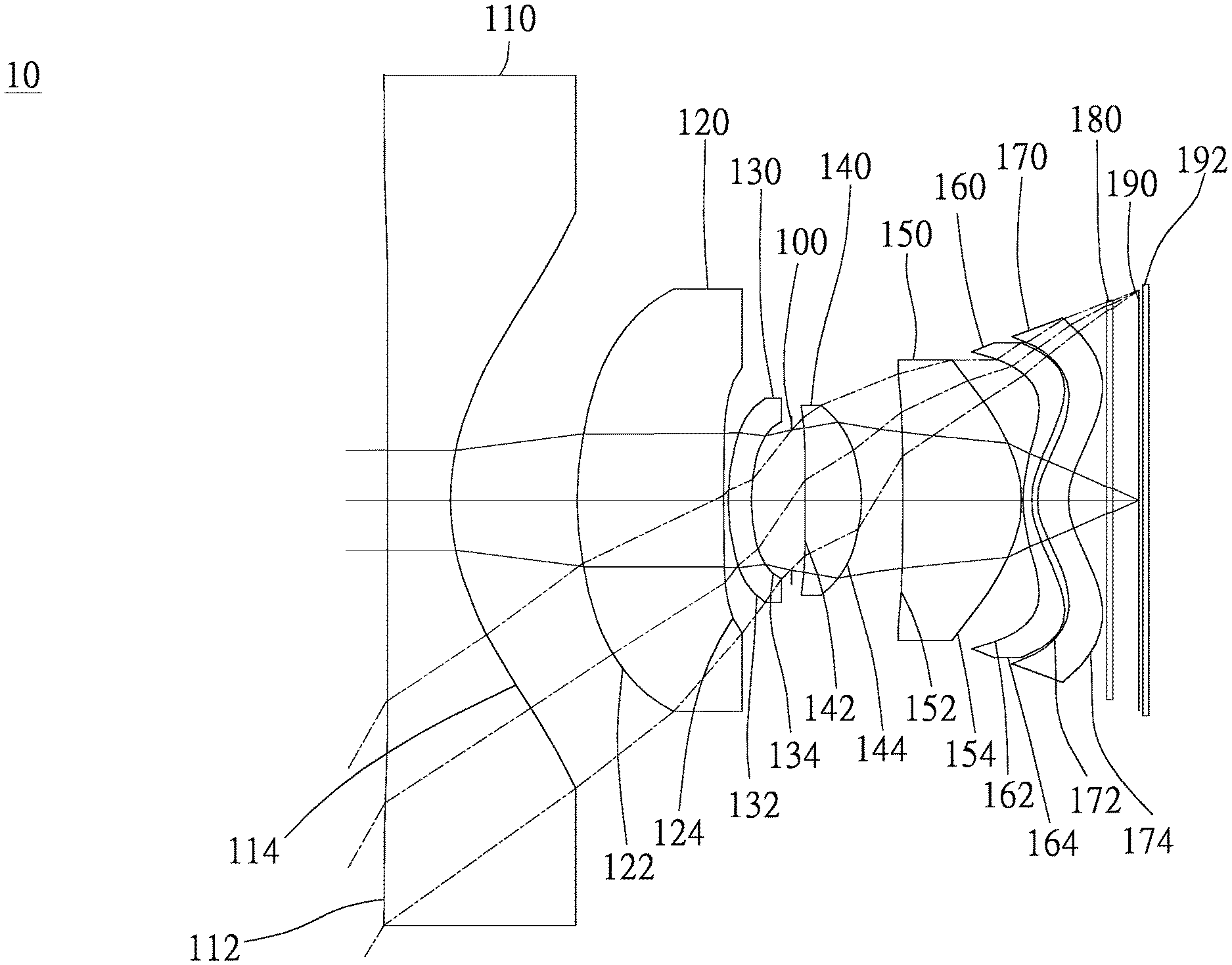
As shown in FIG. 1A and FIG. 1B, an optical image capturing system 10 of the first embodiment of the present invention includes, along an optical axis from an object side to an image side, a first lens 110, an aperture 100, a second lens 120, a third lens 130, a fourth lens 140, a fifth lens 150, a sixth lens 160, a seventh lens 170, an infrared rays filter 180, an image plane 190, and an image sensor 192. FIG. 1C shows a tangential fan and a sagittal fan of the optical image capturing system 10 of the first embodiment of the present application, and a transverse aberration diagram at 0.7 field of view when a longest operation wavelength and a shortest operation wavelength pass through an edge of the aperture 100.
The first lens 110 has negative refractive power and is made of plastic. An object-side surface 112 thereof, which faces the object side, is a concave aspheric surface, and an image-side surface 114 thereof, which faces the image side, is a concave aspheric surface. The object-side surface 112 has an inflection point, and the image-side surface 114 has two inflection points. A profile curve length of the maximum effective half diameter of an object-side surface of the first lens 110 is denoted by ARS11, and a profile curve length of the maximum effective half diameter of the image-side surface of the first lens 110 is denoted by ARS12. A profile curve length of a half of an entrance pupil diameter (HEP) of the object-side surface of the first lens 110 is denoted by ARE11, and a profile curve length of a half of the entrance pupil diameter (HEP) of the image-side surface of the first lens 110 is denoted by ARE12. A thickness of the first lens 110 on the optical axis is TP1.
The first lens 110 satisfies SGI111=-0.1110 mm; SGI121=2.7120 mm; TP1=2.2761 mm; |SGI111|/(|SGI111|+TP1)=0.0465; |SGI121|/(|SGI121|+TP1)=0.5437, where a displacement in parallel with the optical axis from a point on the object-side surface of the first lens, through which the optical axis passes, to the inflection point on the image-side surface, which is the closest to the optical axis is denoted by SGI111, and a displacement in parallel with the optical axis from a point on the image-side surface of the first lens, through which the optical axis passes, to the inflection point on the image-side surface, which is the closest to the optical axis is denoted by SGI121.
The first lens 110 satisfies SGI112=0 mm; SGI122=4.2315 mm; |SGI112|/(|SGI112|+TP1)=0; |SGI122|/(|SGI122|+TP1)=0.6502, where a displacement in parallel with the optical axis from a point on the object-side surface of the first lens, through which the optical axis passes, to the inflection point on the image-side surface, which is the second closest to the optical axis is denoted by SGI112, and a displacement in parallel with the optical axis from a point on the image-side surface of the first lens, through which the optical axis passes, to the inflection point on the image-side surface, which is the second closest to the optical axis is denoted by SGI122.
The first lens 110 satisfies HIF111=12.8432 mm; HIF111/HOI=1.7127; HIF121=7.1744 mm; HIF121/HOI=0.9567, where a displacement perpendicular to the optical axis from a point on the object-side surface of the first lens, through which the optical axis passes, to the inflection point, which is the closest to the optical axis is denoted by HIF111, and a displacement perpendicular to the optical axis from a point on the image-side surface of the first lens, through which the optical axis passes, to the inflection point, which is the closest to the optical axis is denoted by HIF121.
The first lens 110 satisfies HIF112=0 mm; HIF112/HOI=0; HIF122=9.8592 mm; HIF122/HOI=1.3147, where a displacement perpendicular to the optical axis from a point on the object-side surface of the first lens, through which the optical axis passes, to the inflection point, which is the second closest to the optical axis is denoted by HIF112, and a displacement perpendicular to the optical axis from a point on the image-side surface of the first lens, through which the optical axis passes, to the inflection point, which is the second closest to the optical axis is denoted by HIF122.
The second lens 120 has positive refractive power and is made of plastic. An object-side surface 122 thereof, which faces the object side, is a convex aspheric surface, and an image-side surface 124 thereof, which faces the image side, is a concave aspheric surface. A profile curve length of the maximum effective half diameter of an object-side surface of the second lens 120 is denoted by ARS21, and a profile curve length of the maximum effective half diameter of the image-side surface of the second lens 120 is denoted by ARS22. A profile curve length of a half of an entrance pupil diameter (HEP) of the object-side surface of the second lens 120 is denoted by ARE21, and a profile curve length of a half of the entrance pupil diameter (HEP) of the image-side surface of the second lens 120 is denoted by ARE22. A thickness of the second lens 120 on the optical axis is TP2.
For the second lens 120, a displacement in parallel with the optical axis from a point on the object-side surface of the second lens, through which the optical axis passes, to the inflection point on the image-side surface, which is the closest to the optical axis is denoted by SGI211, and a displacement in parallel with the optical axis from a point on the image-side surface of the second lens, through which the optical axis passes, to the inflection point on the image-side surface, which is the closest to the optical axis is denoted by SGI221.
For the second lens, a displacement perpendicular to the optical axis from a point on the object-side surface of the second lens, through which the optical axis passes, to the inflection point, which is the closest to the optical axis is denoted by HIF211, and a displacement perpendicular to the optical axis from a point on the image-side surface of the second lens, through which the optical axis passes, to the inflection point, which is the closest to the optical axis is denoted by HIF221.
The third lens 130 has negative refractive power and is made of plastic. An object-side surface 132, which faces the object side, is a convex aspheric surface, and an image-side surface 134, which faces the image side, is a concave aspheric surface. A profile curve length of the maximum effective half diameter of an object-side surface of the third lens 130 is denoted by ARS31, and a profile curve length of the maximum effective half diameter of the image-side surface of the third lens 130 is denoted by ARS32. A profile curve length of a half of an entrance pupil diameter (HEP) of the object-side surface of the third lens 130 is denoted by ARE31, and a profile curve length of a half of the entrance pupil diameter (HEP) of the image-side surface of the third lens 130 is denoted by ARE32. A thickness of the third lens 130 on the optical axis is TP3.
For the third lens 130, SGI311 is a displacement in parallel with the optical axis, from a point on the object-side surface of the third lens, through which the optical axis passes, to the inflection point on the object-side surface, which is the closest to the optical axis, and SGI321 is a displacement in parallel with the optical axis, from a point on the image-side surface of the third lens, through which the optical axis passes, to the inflection point on the image-side surface, which is the closest to the optical axis.
For the third lens 130, SGI312 is a displacement in parallel with the optical axis, from a point on the object-side surface of the third lens, through which the optical axis passes, to the inflection point on the object-side surface, which is the second closest to the optical axis, and SGI322 is a displacement in parallel with the optical axis, from a point on the image-side surface of the third lens, through which the optical axis passes, to the inflection point on the object-side surface, which is the second closest to the optical axis.
For the third lens 130, HIF311 is a distance perpendicular to the optical axis between the inflection point on the object-side surface of the third lens, which is the closest to the optical axis, and the optical axis; HIF321 is a distance perpendicular to the optical axis between the inflection point on the image-side surface of the third lens, which is the closest to the optical axis, and the optical axis.
For the third lens 130, HIF312 is a distance perpendicular to the optical axis between the inflection point on the object-side surface of the third lens, which is the second closest to the optical axis, and the optical axis; HIF322 is a distance perpendicular to the optical axis between the inflection point on the image-side surface of the third lens, which is the second closest to the optical axis, and the optical axis.
The fourth lens 140 has positive refractive power and is made of plastic. An object-side surface 142, which faces the object side, is a convex aspheric surface, and an image-side surface 144, which faces the image side, is a convex aspheric surface. The object-side surface 142 has an inflection point. A profile curve length of the maximum effective half diameter of an object-side surface of the fourth lens 140 is denoted by ARS41, and a profile curve length of the maximum effective half diameter of the image-side surface of the fourth lens 140 is denoted by ARS42. A profile curve length of a half of an entrance pupil diameter (HEP) of the object-side surface of the fourth lens 140 is denoted by ARE41, and a profile curve length of a half of the entrance pupil diameter (HEP) of the image-side surface of the fourth lens 140 is denoted by ARE42. A thickness of the fourth lens 140 on the optical axis is TP4.
The fourth lens 140 satisfies SGI411=0.0018 mm; |SGI411|/(|SGI411|+TP4)=0.0009, where SGI411 is a displacement in parallel with the optical axis, from a point on the object-side surface of the fourth lens, through which the optical axis passes, to the inflection point on the object-side surface, which is the closest to the optical axis, and SGI421 is a displacement in parallel with the optical axis, from a point on the image-side surface of the fourth lens, through which the optical axis passes, to the inflection point on the image-side surface, which is the closest to the optical axis.
For the fourth lens 140, SGI412 is a displacement in parallel with the optical axis, from a point on the object-side surface of the fourth lens, through which the optical axis passes, to the inflection point on the object-side surface, which is the second closest to the optical axis, and SGI422 is a displacement in parallel with the optical axis, from a point on the image-side surface of the fourth lens, through which the optical axis passes, to the inflection point on the object-side surface, which is the second closest to the optical axis.
The fourth lens 140 further satisfies HIF411=0.7191 mm; HIF411/HOI=0.0959, where HIF411 is a distance perpendicular to the optical axis between the inflection point on the object-side surface of the fourth lens, which is the closest to the optical axis, and the optical axis; HIF421 is a distance perpendicular to the optical axis between the inflection point on the image-side surface of the fourth lens, which is the closest to the optical axis, and the optical axis.
For the fourth lens 140, HIF412 is a distance perpendicular to the optical axis between the inflection point on the object-side surface of the fourth lens, which is the second closest to the optical axis, and the optical axis; HIF422 is a distance perpendicular to the optical axis between the inflection point on the image-side surface of the fourth lens, which is the second closest to the optical axis, and the optical axis.
The fifth lens 150 has positive refractive power and is made of plastic. An object-side surface 152, which faces the object side, is a concave aspheric surface, and an image-side surface 154, which faces the image side, is a convex aspheric surface. The object-side surface 152 and the image-side surface 154 both have an inflection point. A profile curve length of the maximum effective half diameter of an object-side surface of the fifth lens 150 is denoted by ARS51, and a profile curve length of the maximum effective half diameter of the image-side surface of the fifth lens 150 is denoted by ARS52. A profile curve length of a half of an entrance pupil diameter (HEP) of the object-side surface of the fifth lens 150 is denoted by ARE51, and a profile curve length of a half of the entrance pupil diameter (HEP) of the image-side surface of the fifth lens 150 is denoted by ARE52. A thickness of the fifth lens 150 on the optical axis is TP5.
The fifth lens 150 satisfies SGI511=-0.1246 mm; SGI521=-2.1477 mm; |SGI511|/(|SGI511|+TP5)=0.0284; |SGI521|/(|SGI521|+TP5)=0.3346, where SGI511 is a displacement in parallel with the optical axis, from a point on the object-side surface of the fifth lens, through which the optical axis passes, to the inflection point on the object-side surface, which is the closest to the optical axis, and SGI521 is a displacement in parallel with the optical axis, from a point on the image-side surface of the fifth lens, through which the optical axis passes, to the inflection point on the image-side surface, which is the closest to the optical axis.
For the fifth lens 150, SGI512 is a displacement in parallel with the optical axis, from a point on the object-side surface of the fifth lens, through which the optical axis passes, to the inflection point on the object-side surface, which is the second closest to the optical axis, and SGI522 is a displacement in parallel with the optical axis, from a point on the image-side surface of the fifth lens, through which the optical axis passes, to the inflection point on the object-side surface, which is the second closest to the optical axis.
The fifth lens 150 further satisfies HIF511=3.8179 mm; HIF521=4.5480 mm; HIF511/HOI=0.5091; HIF521/HOI=0.6065, where HIF511 is a distance perpendicular to the optical axis between the inflection point on the object-side surface of the fifth lens, which is the closest to the optical axis, and the optical axis; HIF521 is a distance perpendicular to the optical axis between the inflection point on the image-side surface of the fifth lens, which is the closest to the optical axis, and the optical axis.
For the fifth lens 150, HIF512 is a distance perpendicular to the optical axis between the inflection point on the object-side surface of the fifth lens, which is the second closest to the optical axis, and the optical axis; HIF522 is a distance perpendicular to the optical axis between the inflection point on the image-side surface of the fifth lens, which is the second closest to the optical axis, and the optical axis.
The sixth lens 160 has negative refractive power and is made of plastic. An object-side surface 162, which faces the object side, is a convex surface, and an image-side surface 164, which faces the image side, is a concave surface. The object-side surface 162 and the image-side surface 164 both have an inflection point. Whereby, incident angle of each field of view for the sixth lens can be effectively adjusted to improve aberration. A profile curve length of the maximum effective half diameter of an object-side surface of the sixth lens 160 is denoted by ARS61, and a profile curve length of the maximum effective half diameter of the image-side surface of the sixth lens 160 is denoted by ARS62. A profile curve length of a half of an entrance pupil diameter (HEP) of the object-side surface of the sixth lens 160 is denoted by ARE61, and a profile curve length of a half of the entrance pupil diameter (HEP) of the image-side surface of the sixth lens 160 is denoted by ARE62. A thickness of the sixth lens 160 on the optical axis is TP6.
The sixth lens 160 satisfies SGI611=0.3208 mm; SGI621=0.5937 mm; |SGI611|/(|SGI611|+TP6)=0.5167; |SGI621|/(|SGI621|+TP6)=0.6643, where SGI611 is a displacement in parallel with the optical axis, from a point on the object-side surface of the sixth lens, through which the optical axis passes, to the inflection point on the object-side surface, which is the closest to the optical axis, and SGI621 is a displacement in parallel with the optical axis, from a point on the image-side surface of the sixth lens, through which the optical axis passes, to the inflection point on the image-side surface, which is the closest to the optical axis.
The sixth lens 160 further satisfies HIF611=1.9655 mm; HIF621=2.0041 mm; HIF611/HOI=0.2621; HIF621/HOI=0.2672, where HIF611 is a distance perpendicular to the optical axis between the inflection point on the object-side surface of the sixth lens, which is the closest to the optical axis, and the optical axis; HIF621 is a distance perpendicular to the optical axis between the inflection point on the image-side surface of the sixth lens, which is the closest to the optical axis, and the optical axis.
The seventh lens 170 has positive refractive power and is made of plastic. An object-side surface 172, which faces the object side, is a convex surface, and an image-side surface 174, which faces the image side, is a concave surface. Whereby, it is helpful to shorten the focal length behind the seventh lens for miniaturization. The object-side surface 172 and the image-side surface 174 both have an inflection point. A profile curve length of the maximum effective half diameter of an object-side surface of the seventh lens 170 is denoted by ARS71, and a profile curve length of the maximum effective half diameter of the image-side surface of the seventh lens 170 is denoted by ARS72. A profile curve length of a half of an entrance pupil diameter (HEP) of the object-side surface of the seventh lens 170 is denoted by ARE71, and a profile curve length of a half of the entrance pupil diameter (HEP) of the image-side surface of the seventh lens 170 is denoted by ARE72. A thickness of the seventh lens 170 on the optical axis is TP7.
The seventh lens 170 satisfies SGI711=0.5212 mm; SGI721=0.5668 mm; |SGI711|/(|SGI711|+TP7)=0.3179; |SGI721|/(|SGI721|+TP7)=0.3364, where SGI711 is a displacement in parallel with the optical axis, from a point on the object-side surface of the seventh lens, through which the optical axis passes, to the inflection point on the object-side surface, which is the closest to the optical axis, and SGI721 is a displacement in parallel with the optical axis, from a point on the image-side surface of the seventh lens, through which the optical axis passes, to the inflection point on the image-side surface, which is the closest to the optical axis.
The seventh lens 170 further satisfies HIF711=1.6707 mm; HIF721=1.8616 mm; HIF711/HOI=0.2228; HIF721/HOI=0.2482, where HIF711 is a distance perpendicular to the optical axis between the inflection point on the object-side surface of the seventh lens, which is the closest to the optical axis, and the optical axis; HIF721 is a distance perpendicular to the optical axis between the inflection point on the image-side surface of the seventh lens, which is the closest to the optical axis, and the optical axis.
The features related to the inflection points in the present embodiment described below are obtained with the main reference wavelength 555 nm.
The infrared rays filter 180 is made of glass and between the seventh lens 170 and the image plane 190. The infrared rays filter 180 gives no contribution to the focal length of the system.
The optical image capturing system 10 of the first embodiment has the following parameters, which are f=4.3019 mm; f/HEP=1.2; HAF=59.9968; and tan(HAF)=1.7318, where f is a focal length of the system; HAF is a half of the maximum field angle; and HEP is an entrance pupil diameter.
The parameters of the lenses of the first embodiment are f1=-14.5286 mm; |f/f1|=0.2961; f7=8.2933; |f1|>f7; and |f1/f7|=1.7519, where f1 is a focal length of the first lens 110; and f7 is a focal length of the seventh lens 170.
The first embodiment further satisfies |f2|+|f3|+|f4|+|f5|+|f6|=144.7494; |f1|+|f7|=22.8219 and |f2|+|f3|+|f4|+|f5|+|f6|>|f1|+|f7|, where f2 is a focal length of the second lens 120, f3 is a focal length of the third lens 130, f4 is a focal length of the fourth lens 140, f5 is a focal length of the fifth lens 150, f6 is a focal length of the sixth lens 160, and f7 is a focal length of the seventh lens 170.
The optical image capturing system 10 of the first embodiment further satisfies .SIGMA.PPR=f/f2+f/f4+f/f5+f/f7=1.7384; .SIGMA.NPR=f/f1+f/f3+f/f6=-0.9999; .SIGMA.PPR/|.SIGMA.NPR|=1.7386; |f/f2|=0.1774; |f/f3|=0.0443; |f/f4|=0.4411; |f/f5|=0.6012; |f/f6|=0.6595; |f/f7|=0.5187, where PPR is a ratio of a focal length f of the optical image capturing system to a focal length fp of each of the lenses with positive refractive power; and NPR is a ratio of a focal length f of the optical image capturing system to a focal length fn of each of lenses with negative refractive power.
The optical image capturing system 10 of the first embodiment further satisfies InTL+BFL=HOS; HOS=26.9789 mm; HOI=7.5 mm; HOS/HOI=3.5977; HOS/f=6.2715; InS=12.4615 mm; and InS/HOS=0.4619, where InTL is a distance between the object-side surface 112 of the first lens 110 and the image-side surface 174 of the seventh lens 170; HOS is a height of the image capturing system, i.e. a distance between the object-side surface 112 of the first lens 110 and the image plane 190; InS is a distance between the aperture 100 and the image plane 190; HOI is a half of a diagonal of an effective sensing area of the image sensor 192, i.e., the maximum image height; and BFL is a distance between the image-side surface 174 of the seventh lens 170 and the image plane 190.
The optical image capturing system 10 of the first embodiment further satisfies .SIGMA.TP=16.0446 mm; and .SIGMA.TP/InTL=0.6559, where .SIGMA.TP is a sum of the thicknesses of the lenses 110-170 with refractive power. It is helpful for the contrast of image and yield rate of manufacture and provides a suitable back focal length for installation of other elements.
The optical image capturing system 10 of the first embodiment further satisfies |R1/R2|=129.9952, where R1 is a radius of curvature of the object-side surface 112 of the first lens 110, and R2 is a radius of curvature of the image-side surface 114 of the first lens 110. It provides the first lens with a suitable positive refractive power to reduce the increase rate of the spherical aberration.
The optical image capturing system 10 of the first embodiment further satisfies (R13-R14)/(R13+R14)=-0.0806, where R13 is a radius of curvature of the object-side surface 172 of the seventh lens 170, and R14 is a radius of curvature of the image-side surface 174 of the seventh lens 170. It may modify the astigmatic field curvature.
The optical image capturing system 10 of the first embodiment further satisfies .SIGMA.PP=f2+f4+f5+f7=49.4535 mm; and f4/(f2+f4+f5+f7)=0.1972, where .SIGMA.PP is a sum of the focal lengths fp of each lens with positive refractive power. It is helpful to share the positive refractive power of the fourth lens 140 to other positive lenses to avoid the significant aberration caused by the incident rays.
The optical image capturing system 10 of the first embodiment further satisfies .SIGMA.NP=f1+f3+f6=-118.1178 mm; and f1/(f1+f3+f6)=0.1677, where .SIGMA.NP is a sum of the focal lengths fn of each lens with negative refractive power. It is helpful to share the negative refractive power of the first lens 110 to other negative lenses, which avoids the significant aberration caused by the incident rays.
The optical image capturing system 10 of the first embodiment further satisfies IN12=4.5524 mm; IN12/f=1.0582, where IN12 is a distance on the optical axis between the first lens 110 and the second lens 120. It may correct chromatic aberration and improve the performance.
The optical image capturing system 10 of the first embodiment further satisfies TP1=2.2761 mm; TP2=0.2398 mm; and (TP1+IN12)/TP2=1.3032, where TP1 is a central thickness of the first lens 110 on the optical axis, and TP2 is a central thickness of the second lens 120 on the optical axis. It may control the sensitivity of manufacture of the system and improve the performance.
The optical image capturing system 10 of the first embodiment further satisfies TP6=0.3000 mm; TP7=1.1182 mm; and (TP7+IN67)/TP6=4.4322, where TP6 is a central thickness of the sixth lens 160 on the optical axis, TP7 is a central thickness of the seventh lens 170 on the optical axis, and IN67 is a distance on the optical axis between the sixth lens 160 and the seventh lens 170. It may control the sensitivity of manufacture of the system and lower the total height of the system.
The optical image capturing system 10 of the first embodiment further satisfies TP3=0.8369 mm; TP4=2.0022 mm; TP5=4.2706 mm; IN34=1.9268 mm; IN45=1.5153 mm; and TP4/(IN34+TP4+IN45)=0.3678, where TP3 is a central thickness of the third lens 130 on the optical axis, TP4 is a central thickness of the fourth lens 140 on the optical axis, TP5 is a central thickness of the fifth lens 150 on the optical axis, IN34 is a distance on the optical axis between the third lens 130 and the fourth lens 140, and IN45 is a distance on the optical axis between the fourth lens 140 and the fifth lens 150. It may control the sensitivity of manufacture of the system and lower the total height of the system.
The optical image capturing system 10 of the first embodiment further satisfies InRS61=-0.7823 mm; InRS62=-0.2166 mm; and .parallel.nRS62|/TP6=0.722, where InRS61 is a displacement in parallel with the optical axis from a point on the object-side surface 162 of the sixth lens 160, through which the optical axis passes, to a point at the maximum effective semi diameter of the object-side surface 162 of the sixth lens; InRS62 is a displacement in parallel with the optical axis from a point on the image-side surface 164 of the sixth lens 160, through which the optical axis passes, to a point at the maximum effective semi diameter of the image-side surface 164 of the sixth lens 160; and TP6 is a central thickness of the sixth lens 160 on the optical axis. It is helpful for manufacturing and shaping of the lenses and is helpful to reduce the size.
The optical image capturing system 10 of the first embodiment further satisfies HVT61=3.3498 mm; HVT62=3.9860 mm; and HVT61/HVT62=0.8404, where HVT61 a distance perpendicular to the optical axis between the critical point on the object-side surface 162 of the sixth lens 160 and the optical axis; and HVT62 a distance perpendicular to the optical axis between the critical point on the image-side surface 164 of the sixth lens 160 and the optical axis.
The optical image capturing system 10 of the first embodiment further satisfies InRS71=-0.2756 mm; InRS72=-0.0938 mm; and .parallel.nRS72|/TP7=0.0839, where InRS71 is a displacement in parallel with the optical axis from a point on the object-side surface 172 of the seventh lens 170, through which the optical axis passes, to a point at the maximum effective semi diameter of the object-side surface 172 of the seventh lens 170; InRS72 is a displacement in parallel with the optical axis from a point on the image-side surface 174 of the seventh lens 170, through which the optical axis passes, to a point at the maximum effective semi diameter of the image-side surface 174 of the seventh lens 170; and TP7 is a central thickness of the seventh lens 170 on the optical axis. It is helpful for manufacturing and shaping of the lenses and is helpful to reduce the size.
The optical image capturing system 10 of the first embodiment satisfies HVT71=3.6822 mm; HVT72=4.0606 mm; and HVT71/HVT72=0.9068, where HVT71 a distance perpendicular to the optical axis between the critical point on the object-side surface 172 of the seventh lens 170 and the optical axis; and HVT72 a distance perpendicular to the optical axis between the critical point on the image-side surface 174 of the seventh lens 170 and the optical axis.
The optical image capturing system 10 of the first embodiment satisfies HVT72/HOI=0.5414. It is helpful for correction of the aberration of the peripheral view field of the optical image capturing system.
The optical image capturing system 10 of the first embodiment satisfies HVT72/HOS=0.1505. It is helpful for correction of the aberration of the peripheral view field of the optical image capturing system.
The second lens 120, the third lens 130, and the seventh lens 170 have negative refractive power. The optical image capturing system 10 of the first embodiment further satisfies1.ltoreq.NA7/NA2, where NA2 is an Abbe number of the second lens 120; and NA7 is an Abbe number of the seventh lens 170. It may correct the aberration of the optical image capturing system.
The optical image capturing system 10 of the first embodiment further satisfies |TDT|=2.5678%; |ODT|=2.1302%, where TDT is TV distortion; and ODT is optical distortion.
For the fifth lens 150 of the optical image capturing system 10 in the first embodiment, a transverse aberration at 0.7 field of view in the positive direction of the tangential fan after the shortest operation wavelength of visible light passing through the edge of the aperture 100 is denoted by PSTA, and is 0.00040 mm; a transverse aberration at 0.7 field of view in the positive direction of the tangential fan after the longest operation wavelength of visible light passing through the edge of the aperture 100 is denoted by PLTA, and is -0.009 mm; a transverse aberration at 0.7 field of view in the negative direction of the tangential fan after the shortest operation wavelength of visible light passing through the edge of the aperture 100 is denoted by NSTA, and is -0.002 mm; a transverse aberration at 0.7 field of view in the negative direction of the tangential fan after the longest operation wavelength of visible light passing through the edge of the aperture 100 is denoted by NLTA, and is -0.016 mm; a transverse aberration at 0.7 field of view of the sagittal fan after the shortest operation wavelength of visible light passing through the edge of the aperture 100 is denoted by SSTA, and is 0.018 mm; a transverse aberration at 0.7 field of view of the sagittal fan after the longest operation wavelength of visible light passing through the edge of the aperture 100 is denoted by SLTA, and is 0.016 mm.
The parameters of the lenses of the first embodiment are listed in Table 1 and Table 2.
TABLE-US-00001 TABLE 1 f = 4.3019 mm; f/HEP = 1.2; HAF = 59.9968 deg Focal Radius of curvature Thickness Refractive Abbe length Surface (mm) (mm) Material index number (mm) 0 Object plane infinity 1 1.sup.st lens -1079.499964 2.276 plastic 1.565 58.00 -14.53 2 8.304149657 4.552 3 2.sup.nd lens 14.39130913 5.240 plastic 1.650 21.40 24.25 4 130.0869482 0.162 5 3.sup.rd lens 8.167310118 0.837 plastic 1.650 21.40 -97.07 6 6.944477468 1.450 7 Aperture plane 0.477 8 4.sup.th lens 121.5965254 2.002 plastic 1.565 58.00 9.75 9 -5.755749302 1.515 10 5.sup.th lens -86.27705938 4.271 plastic 1.565 58.00 7.16 11 -3.942936258 0.050 12 6.sup.th lens 4.867364751 0.300 plastic 1.650 21.40 -6.52 13 2.220604983 0.211 14 7.sup.th lens 1.892510651 1.118 plastic 1.650 21.40 8.29 15 2.224128115 1.400 16 Infrared plane 0.200 BK_7 1.517 64.2 rays filter 17 plane 0.917 18 Image plane plane Reference wavelength (d-line): 555 nm.
TABLE-US-00002 TABLE 2 Coefficients of the aspheric surfaces Surface 1 2 3 4 5 6 8 k 2.500000E+01 -4.711931E-01 1.531617E+00 -1.153034E+01 -2.915013E+00 4.886991E+00 -3.459463E+01 A4 5.236918E-06 -2.117558E-04 7.146736E-05 4.353586E-04 5.793768E-04 -3.75- 6697E-04 -1.292614E-03 A6 -3.014384E-08 -1.838670E-06 2.334364E-06 1.400287E-05 2.112652E-04 3.901218E-04 -1.602- 381E-05 A8 -2.487400E-10 9.605910E-09 -7.479362E-08 -1.688929E-07 -1.344586E-05 -4.925422E-05 -8.452359E-06 A10 1.170000E-12 -8.256000E-11 1.701570E-09 3.829807E-08 1.000482E-06 4.13- 9741E-06 7.243999E-07 A12 0.000000E+00 0.000000E+00 0.000000E+00 0.000000E+00 0.000000E+00 0.000000E+00 0.000000E+00 A14 0.000000E+00 0.000000E+00 0.000000E+00 0.000000E+00 0.000000E+00 0.000000E+00 0.000000E+00 Surface 9 10 11 12 13 14 15 k -7.549291E+00 -5.000000E+01 -1.740728E+00 -4.709650E+00 -4.509781E+00 -3.427137E+00 -3.215123E+00 A4 -5.583548E-03 1.240671E-04 6.467538E-04 -1.872317E-03 -8.967310E-04 -3.- 189453E-03 -2.815022E-03 A6 1.947110E-04 -4.949077E-05 -4.981838E-05 -1.523141E-05 -2.688331E-05 -1.058126E-05 1.884580E-05 A8 -1.486947E-05 2.088854E-06 9.129031E-07 -2.169414E-06 -8.324958E-07 1.760103E-06 -1.017223E-08 A10 -6.501246E-08 -1.438383E-08 7.108550E-09 -2.308304E-08 -6.184250E-09 -4.730294E-08 3.660000E-12 A12 0.000000E+00 0.000000E+00 0.000000E+00 0.000000E+00 0.000000E+00 0.000000E+00 0.000000E+00 A14 0.000000E+00 0.000000E+00 0.000000E+00 0.000000E+00 0.000000E+00 0.000000E+00 0.000000E+00
The figures related to the profile curve lengths obtained based on Table 1 and Table 2 are listed in the following table:
TABLE-US-00003 First embodiment (Reference wavelength: 555 nm) ARE ARE - 1/2 2(ARE/ ARE/ ARE 1/2(HEP) value (HEP) HEP) % TP TP (%) 11 1.792 1.792 -0.00044 99.98% 2.276 78.73% 12 1.792 1.806 0.01319 100.74% 2.276 79.33% 21 1.792 1.797 0.00437 100.24% 5.240 34.29% 22 1.792 1.792 -0.00032 99.98% 5.240 34.20% 31 1.792 1.808 0.01525 100.85% 0.837 216.01% 32 1.792 1.819 0.02705 101.51% 0.837 217.42% 41 1.792 1.792 -0.00041 99.98% 2.002 89.50% 42 1.792 1.825 0.03287 101.83% 2.002 91.16% 51 1.792 1.792 -0.00031 99.98% 4.271 41.96% 52 1.792 1.845 0.05305 102.96% 4.271 43.21% 61 1.792 1.818 0.02587 101.44% 0.300 606.10% 62 1.792 1.874 0.08157 104.55% 0.300 624.67% 71 1.792 1.898 0.10523 105.87% 1.118 169.71% 72 1.792 1.885 0.09273 105.17% 1.118 168.59% ARS ARS - (ARS/ ARS/ ARS EHD value EHD EHD) % TP TP (%) 11 15.095 15.096 0.001 100.01% 2.276 663.24% 12 10.315 11.377 1.062 110.29% 2.276 499.86% 21 7.531 8.696 1.166 115.48% 5.240 165.96% 22 4.759 4.881 0.122 102.56% 5.240 93.15% 31 3.632 4.013 0.382 110.51% 0.837 479.55% 32 2.815 3.159 0.344 112.23% 0.837 377.47% 41 2.967 2.971 0.004 100.13% 2.002 148.38% 42 3.402 3.828 0.426 112.53% 2.002 191.20% 51 4.519 4.523 0.004 100.10% 4.271 105.91% 52 5.016 5.722 0.706 114.08% 4.271 133.99% 61 5.019 5.823 0.805 116.04% 0.300 1941.14% 62 5.629 6.605 0.976 117.34% 0.300 2201.71% 71 5.634 6.503 0.869 115.43% 1.118 581.54% 72 6.488 7.152 0.664 110.24% 1.118 639.59%
The detail parameters of the first embodiment are listed in Table 1, in which the unit of the radius of curvature, thickness, and focal length are millimeter, and surface 0-10 indicates the surfaces of all elements in the system in sequence from the object side to the image side. Table 2 is the list of coefficients of the aspheric surfaces, in which A1-A20 indicate the coefficients of aspheric surfaces from the first order to the twentieth order of each aspheric surface. The following embodiments have the similar diagrams and tables, which are the same as those of the first embodiment, so we do not describe it again.
Second Embodiment
As shown in FIG. 2A and FIG. 2B, an optical image capturing system 20 of the second embodiment of the present invention includes, along an optical axis from an object side to an image side, a first lens 210, a second lens 220, a third lens 230, an aperture 200, a fourth lens 240, a fifth lens 250, a sixth lens 260, a seven lens 270, an infrared rays filter 280, an image plane 290, and an image sensor 292. FIG. 2C is a transverse aberration diagram at 0.7 field of view of the second embodiment of the present application.
The first lens 210 has negative refractive power and is made of glass. An object-side surface 212 thereof, which faces the object side, is a convex surface, and an image-side surface 214 thereof, which faces the image side, is a concave surface.
The second lens 220 has negative refractive power and is made of glass. An object-side surface 222 thereof, which faces the object side, is a concave surface, and an image-side surface 224 thereof, which faces the image side, is a concave surface.
The third lens 230 has positive refractive power and is made of plastic. An object-side surface 232, which faces the object side, is a convex aspheric surface, and an image-side surface 234, which faces the image side, is a convex aspheric surface.
The fourth lens 240 has positive refractive power and is made of plastic. An object-side surface 242, which faces the object side, is a convex aspheric surface, and an image-side surface 244, which faces the image side, is a convex aspheric surface. The image-side surface 244 has two inflection points.
The fifth lens 250 has negative refractive power and is made of plastic. An object-side surface 252, which faces the object side, is a convex aspheric surface, and an image-side surface 254, which faces the image side, is a concave aspheric surface. The object-side surface 252 has an inflection point.
The sixth lens 260 has positive refractive power and is made of plastic. An object-side surface 262, which faces the object side, is a convex aspheric surface, and an image-side surface 264, which faces the image side, is a convex aspheric surface. The image-side surface 264 has an inflection point. Whereby, incident angle of each field of view for the sixth lens can be effectively adjusted to improve aberration.
The seventh lens 270 has negative refractive power and is made of plastic. An object-side surface 272, which faces the object side, is a convex surface, and an image-side surface 274, which faces the image side, is a concave surface. It may help to shorten the back focal length to keep small in size. In addition, the object-side surface 272 and the image-side surface 274 both have an inflection point, which may reduce an incident angle of the light of an off-axis field of view and correct the aberration of the off-axis field of view.
The infrared rays filter 280 is made of glass and between the seventh lens 270 and the image plane 290. The infrared rays filter 280 gives no contribution to the focal length of the system.
The parameters of the lenses of the second embodiment are listed in Table 3 and Table 4.
TABLE-US-00004 TABLE 3 f = 2.5840 mm; f/HEP = 1.2; HAF = 100 deg Focal Radius of curvature Thickness Refractive Abbe length Surface (mm) (mm) Material index number (mm) 0 Object 1E+18 1E+18 1 1.sup.st lens 98.54233146 8.047 glass 1.834 37.16 -18.733 2 13.03803836 8.545 3 2.sup.nd lens -63.14471825 2.816 glass 1.497 81.61 -19.248 4 11.47206375 3.122 5 3.sup.rd lens 49.99533973 7.110 plastic 1.661 20.40 41.165 6 -57.4026272 15.535 7 Aperture 1E+18 0.276 8 4.sup.th lens 8.224850411 4.835 plastic 1.565 58.00 7.874 9 -7.681153484 0.682 10 5.sup.th lens 18.6012531 2.423 plastic 1.661 20.40 -6.473 11 3.320632709 1.376 12 6.sup.th lens 8.650237652 6.075 plastic 1.565 58.00 5.784 13 -3.937994762 0.050 14 7.sup.th lens 7.919737432 1.981 plastic 1.661 20.40 -19.192 15 4.402750994 1.000 16 Infrared 1E+18 0.300 BK_7 1.517 64.2 rays filter 17 1E+18 0.293 18 Image 1E+18 0.012 plane Reference wavelength (d-line): 555 nm.
TABLE-US-00005 TABLE 4 Coefficients of the aspheric surfaces Surface 1 2 3 4 5 6 8 k 0.000000E+00 0.000000E+00 0.000000E+00 0.000000E+00 -9.793388E-01 2.973766E+01 -1.282558E+00 A4 0.000000E+00 0.000000E+00 0.000000E+00 0.000000E+00 1.600884E-04 7.6274- 11E-05 3.434528E-04 A6 0.000000E+00 0.000000E+00 0.000000E+00 0.000000E+00 -6.759980E-07 -9.003446E-07 4.838355E-06 A8 0.000000E+00 0.000000E+00 0.000000E+00 0.000000E+00 -1.513934E-09 6.883603E-10 -7.241633E-08 A10 0.000000E+00 0.000000E+00 0.000000E+00 0.000000E+00 8.856071E-12 2.075- 482E-11 2.415549E-09 A12 0.000000E+00 0.000000E+00 0.000000E+00 0.000000E+00 0.000000E+00 0.000- 000E+00 0.000000E+00 A14 0.000000E+00 0.000000E+00 0.000000E+00 0.000000E+00 0.000000E+00 0.000- 000E+00 0.000000E+00 A16 0.000000E+00 0.000000E+00 0.000000E+00 0.000000E+00 0.000000E+00 0.000- 000E+00 0.000000E+00 Surface 9 10 11 12 13 14 15 k -1.082510E+01 -2.713995E+00 -3.089713E+00 -8.674479E+00 -2.994548E+00 -1.384385E+01 -7.048734E+00 A4 2.131522E-04 -1.338022E-03 7.116467E-04 8.630247E-04 -7.673225E-05 -3.692189E-04 -3.735106E-03 A6 4.028433E-06 -5.103150E-06 -4.937205E-05 5.221615E-06 -9.294062E-07 -5.110795E-05 7.429126E-06 A8 -2.510669E-07 -3.450694E-07 1.099474E-06 -6.434929E-07 2.043935E-07 -8.617002E-07 1.681013E-06 A10 2.063084E-09 1.103283E-09 -5.600144E-09 1.153576E-08 9.372014E-10 -4.741607E-08 -4.222700E-08 A12 0.000000E+00 0.000000E+00 0.000000E+00 0.000000E+00 0.000000E+00 0.000000E+00 0.000000E+00 A14 0.000000E+00 0.000000E+00 0.000000E+00 0.000000E+00 0.000000E+00 0.000000E+00 0.000000E+00 A16 0.000000E+00 0.000000E+00 0.000000E+00 0.000000E+00 0.000000E+00 0.000000E+00 0.000000E+00
An equation of the aspheric surfaces of the second embodiment is the same as that of the first embodiment, and the definitions are the same as well.
The exact parameters of the second embodiment based on Table 3 and Table 4 are listed in the following table:
TABLE-US-00006 Second embodiment (Reference wavelength: 555 nm) |f/f1| |f/f2| |f/f3| |f/f4| |f/f5| |f/f6| 0.1379 0.1342 0.0628 0.3282 0.3992 0.4467 |f/f7| .SIGMA.PPR .SIGMA.NPR .SIGMA.PPR/|.SIGMA.NPR| IN12/f IN67/f 0.1346 0.9723 0.6714 1.4482 3.3070 0.0193 |f1/f2| |f2/f3| (TP1 + IN12)/TP2 (TP7 + IN67)/TP6 0.9732 0.4676 5.8916 0.3343 HOS InTL HOS/HOI InS/HOS ODT % TDT % 64.4768 62.8722 12.8954 0.2994 -134.1300 102.4620 HVT11 HVT12 HVT21 HVT22 HVT31 HVT32 0.0000 0.0000 0.0000 0.0000 0.0000 0.0000 HVT61 HVT62 HVT71 HVT72 HVT72/HOI HVT72/HOS 0.0000 0.0000 3.3219 2.9266 0.5853 0.0454 PSTA PLTA NSTA NLTA SSTA SLTA 0.010 mm 0.008 mm 0.025 mm -0.013 mm 0.009 mm 0.010 mm
The figures related to the profile curve lengths obtained based on Table 3 and Table 4 are listed in the following table:
TABLE-US-00007 Second embodiment (Reference wavelength: 555 nm) ARE ARE - 1/2 2(ARE/ ARE/ ARE 1/2(HEP) value (HEP) HEP) % TP TP (%) 11 1.077 1.076 -0.00064 99.94% 8.047 13.37% 12 1.077 1.077 0.00056 100.05% 8.047 13.39% 21 1.077 1.076 -0.00061 99.94% 2.816 38.21% 22 1.077 1.078 0.00092 100.09% 2.816 38.26% 31 1.077 1.076 -0.00058 99.95% 7.110 15.13% 32 1.077 1.076 -0.00060 99.94% 7.110 15.13% 41 1.077 1.079 0.00244 100.23% 4.835 22.32% 42 1.077 1.079 0.00246 100.23% 4.835 22.32% 51 1.077 1.077 -0.00015 99.99% 2.423 44.43% 52 1.077 1.093 0.01601 101.49% 2.423 45.09% 61 1.077 1.079 0.00203 100.19% 6.075 17.76% 62 1.077 1.088 0.01154 101.07% 6.075 17.91% 71 1.077 1.079 0.00218 100.20% 1.981 54.47% 72 1.077 1.084 0.00730 100.68% 1.981 54.73% ARS ARS - (ARS/ ARS/ ARS EHD value EHD EHD) % TP TP (%) 11 24.497 24.756 0.259 101.06% 8.047 307.65% 12 11.650 14.409 2.759 123.68% 8.047 179.07% 21 11.459 11.523 0.064 100.56% 2.816 409.16% 22 9.072 10.464 1.391 115.34% 2.816 371.55% 31 9.104 9.291 0.187 102.06% 7.110 130.68% 32 8.848 8.902 0.054 100.61% 7.110 125.21% 41 4.851 5.220 0.368 107.59% 4.835 107.96% 42 4.718 4.796 0.078 101.66% 4.835 99.20% 51 4.404 4.428 0.024 100.54% 2.423 182.74% 52 4.497 4.962 0.465 110.33% 2.423 204.77% 61 5.152 5.470 0.318 106.18% 6.075 90.04% 62 5.210 5.701 0.491 109.42% 6.075 93.86% 71 4.733 5.035 0.302 106.37% 1.981 254.23% 72 5.324 5.845 0.521 109.79% 1.981 295.14%
The results of the equations of the second embodiment based on Table 3 and Table 4 are listed in the following table:
TABLE-US-00008 Values related to the inflection points of the second embodiment (Reference wavelength: 555 nm) HIF421 3.3410 HIF421/HOI 0.6682 SGI421 -0.5114 |SGI421|/(|SGI421| + TP4) 0.0957 HIF422 4.5580 HIF422/HOI 0.9116 SGI422 -0.7798 |SGI422|/(|SGI422| + TP4) 0.1389 HIF511 1.7724 HIF511/HOI 0.3545 SGI511 0.0707 |SGI511|/(|SGI511| + TP5) 0.0284 HIF621 4.1717 HIF621/HOI 0.8343 SGI621 -1.5864 |SGI621|/(|SGI621| + TP6) 0.2071 HIF711 2.0427 HIF711/HOI 0.4085 SGI711 0.2126 |SGI711|/(|SGI711| + TP7) 0.0969 HIF721 1.5165 HIF721/HOI 0.3033 SGI721 0.2065 |SGI721|/(|SGI721| + TP7) 0.0944
Third Embodiment
As shown in FIG. 3A and FIG. 3B, an optical image capturing system of the third embodiment of the present invention includes, along an optical axis from an object side to an image side, a first lens 310, a second lens 320, a third lens 330, an aperture 300, a fourth lens 340, a fifth lens 350, a sixth lens 360, a seventh lens 370, an infrared rays filter 380, an image plane 390, and an image sensor 392. FIG. 3C is a transverse aberration diagram at 0.7 field of view of the third embodiment of the present application.
The first lens 310 has negative refractive power and is made of glass. An object-side surface 312 thereof, which faces the object side, is a convex surface, and an image-side surface 314 thereof, which faces the image side, is a concave surface.
The second lens 320 has negative refractive power and is made of glass. An object-side surface 322 thereof, which faces the object side, is a concave surface, and an image-side surface 324 thereof, which faces the image side, is a concave surface.
The third lens 330 has positive refractive power and is made of plastic. An object-side surface 332 thereof, which faces the object side, is a convex aspheric surface, and an image-side surface 334 thereof, which faces the image side, is a convex aspheric surface.
The fourth lens 340 has positive refractive power and is made of plastic. An object-side surface 342, which faces the object side, is a convex aspheric surface, and an image-side surface 344, which faces the image side, is a convex aspheric surface.
The fifth lens 350 has negative refractive power and is made of plastic. An object-side surface 352, which faces the object side, is a concave aspheric surface, and an image-side surface 354, which faces the image side, is a concave aspheric surface. The image-side surface 354 has an inflection point.
The sixth lens 360 has positive refractive power and is made of plastic. An object-side surface 362, which faces the object side, is a convex surface, and an image-side surface 364, which faces the image side, is a convex surface. The image-side surface 364 has an inflection point. The image-side surface 364 has an inflection point. Whereby, incident angle of each field of view for the sixth lens can be effectively adjusted to improve aberration.
The seventh lens 370 has positive refractive power and is made of plastic. An object-side surface 372, which faces the object side, is a convex surface, and an image-side surface 374, which faces the image side, is a concave surface. It may help to shorten the back focal length to keep small in size. In addition, the object-side surface 372 and the image-side surface 374 both have an inflection point, which may reduce an incident angle of the light of an off-axis field of view and correct the aberration of the off-axis field of view.
The infrared rays filter 380 is made of glass and between the seventh lens 370 and the image plane 390. The infrared rays filter 390 gives no contribution to the focal length of the system.
The parameters of the lenses of the third embodiment are listed in Table 5 and Table 6.
TABLE-US-00009 TABLE 5 f = 3.7004 mm; f/HEP = 1.2; HAF = 70.0003 deg Radius of curvature Thickness Refractive Abbe Focal length Surface (mm) (mm) Material index number (mm) 0 Object 1E+18 1E+18 1 1.sup.st lens 33.9458289 6.763 glass 1.497 81.61 -35.421 2 10.8405598 6.930 3 2.sup.nd lens -66.97315291 4.236 glass 1.497 81.61 -10.711 4 5.919261013 8.213 5 3.sup.rd lens 20.24799947 5.315 plastic 1.565 54.50 9.832 6 -6.960408704 -1.233 7 Aperture 1E+18 2.239 8 4.sup.th lens 12.13055189 3.990 plastic 1.565 58.00 11.722 9 -12.94165934 0.104 10 5.sup.th lens -35.63020232 1.161 plastic 1.661 20.40 -6.155 11 4.699316236 0.670 12 6.sup.th lens 5.545669865 3.709 plastic 1.565 58.00 8.516 13 -28.21381415 1.250 14 7.sup.th lens 9.280768369 1.524 plastic 1.661 20.40 -126.918 15 7.814031928 1.000 16 Infrared 1E+18 0.300 BK_7 1.517 64.2 rays filter 17 1E+18 0.220 18 Image 1E+18 0.004 plane Reference wavelength (d-line): 555 nm.
TABLE-US-00010 TABLE 6 Coefficients of the aspheric surfaces Surface 1 2 3 4 5 6 8 k 0.000000E+00 0.000000E+00 0.000000E+00 0.000000E+00 -1.621510E+01 -3.205- 843E-01 -3.949323E+00 A4 0.000000E+00 0.000000E+00 0.000000E+00 0.000000E+00 -1.852939E-04 5.921- 411E-04 2.986636E-04 A6 0.000000E+00 0.000000E+00 0.000000E+00 0.000000E+00 -2.358871E-06 -1.07- 9554E-06 2.117306E-05 A8 0.000000E+00 0.000000E+00 0.000000E+00 0.000000E+00 -7.757225E-09 -2.12- 5122E-07 -3.015400E-07 A10 0.000000E+00 0.000000E+00 0.000000E+00 0.000000E+00 8.671595E-09 1.070195E-08 7.441789E-09 A12 0.000000E+00 0.000000E+00 0.000000E+00 0.000000E+00 0.000000E+00 0.000000E+00 0.000000E+00 A14 0.000000E+00 0.000000E+00 0.000000E+00 0.000000E+00 0.000000E+00 0.000000E+00 0.000000E+00 A16 0.000000E+00 0.000000E+00 0.000000E+00 0.000000E+00 0.000000E+00 0.000000E+00 0.000000E+00 Surface 9 10 11 12 13 14 15 k 3.405073E+00 4.384252E+01 -3.791675E+00 -4.569282E+00 2.754744E+01 2.200788E+00 -5.881090E+00 A4 5.091138E-04 3.717279E-06 9.868087E-04 1.287730E-03 -7.359233E-04 -5.075236E-03 -2.194556E-03 A6 -2.656989E-05 -7.027377E-05 -4.854722E-05 4.963414E-05 1.664292E-04 -6.448258E-05 -9.316784E-05 A8 3.838327E-07 2.308340E-07 -2.115132E-06 -2.274142E-06 -2.439957E-06 8.434158E-06 5.831964E-07 A10 1.106316E-08 4.774476E-08 8.591432E-08 6.341487E-08 2.079774E-07 -5.32- 7453E-07 5.216406E-08 A12 0.000000E+00 0.000000E+00 0.000000E+00 0.000000E+00 0.000000E+00 0.000- 000E+00 0.000000E+00 A14 0.000000E+00 0.000000E+00 0.000000E+00 0.000000E+00 0.000000E+00 0.000- 000E+00 0.000000E+00 A16 0.000000E+00 0.000000E+00 0.000000E+00 0.000000E+00 0.000000E+00 0.000- 000E+00 0.000000E+00
An equation of the aspheric surfaces of the third embodiment is the same as that of the first embodiment, and the definitions are the same as well.
The exact parameters of the third embodiment based on Table 5 and Table 6 are listed in the following table:
TABLE-US-00011 Third embodiment (Reference wavelength: 555 nm) |f/f1| |f/f2| |f/f3| |f/f4| |f/f5| |f/f6| 0.1045 0.3455 0.3764 0.3157 0.6012 0.4345 |f/f7| .SIGMA.PPR .SIGMA.NPR .SIGMA.PPR/|.SIGMA.NPR| IN12/f IN67/f 0.0292 1.1557 1.0511 1.0995 1.8727 0.3379 |f1/f2| |f2/f3| (TP1 + IN12)/TP2 (TP7 + IN67)/TP6 3.3069 1.0894 3.2323 0.7481 HOS InTL HOS/HOI InS/HOS ODT % TDT % 46.3961 44.8723 9.2792 0.3486 -50.8268 32.4748 HVT11 HVT12 HVT21 HVT22 HVT31 HVT32 0.0000 0.0000 0.0000 0.0000 0.0000 0.0000 HVT61 HVT62 HVT71 HVT72 HVT72/HOI HVT72/HOS 0.0000 2.8708 2.3870 2.8135 0.5627 0.0606 PSTA PLTA NSTA NLTA SSTA SLTA -0.001 mm 0.012 mm 0.005 mm -0.007 mm 0.012 mm 0.006 mm
The figures related to the profile curve lengths obtained based on Table 5 and Table 6 are listed in the following table:
TABLE-US-00012 Third embodiment (Reference wavelength: 555 nm) ARE ARE - 1/2 2(ARE/ ARE/ ARE 1/2(HEP) value (HEP) HEP) % TP TP (%) 11 1.542 1.542 -0.00031 99.98% 6.763 22.79% 12 1.542 1.546 0.00440 100.29% 6.763 22.86% 21 1.542 1.541 -0.00070 99.95% 4.236 36.38% 22 1.542 1.559 0.01712 101.11% 4.236 36.80% 31 1.542 1.542 0.00051 100.03% 5.315 29.02% 32 1.542 1.553 0.01134 100.74% 5.315 29.22% 41 1.542 1.545 0.00338 100.22% 3.990 38.73% 42 1.542 1.545 0.00270 100.18% 3.990 38.71% 51 1.542 1.542 -0.00030 99.98% 1.161 132.74% 52 1.542 1.565 0.02350 101.52% 1.161 134.78% 61 1.542 1.560 0.01770 101.15% 3.709 42.05% 62 1.542 1.542 0.00005 100.00% 3.709 41.57% 71 1.542 1.545 0.00325 100.21% 1.524 101.36% 72 1.542 1.548 0.00624 100.40% 1.524 101.56% ARS ARS - (ARS/ ARS/ ARS EHD value EHD EHD) % TP TP (%) 11 20.150 21.573 1.423 107.06% 6.763 318.98% 12 9.784 12.200 2.416 124.70% 6.763 180.39% 21 9.711 9.744 0.034 100.35% 4.236 230.02% 22 5.267 6.491 1.224 123.24% 4.236 153.22% 31 4.765 4.786 0.020 100.42% 5.315 90.04% 32 4.330 4.554 0.224 105.17% 5.315 85.68% 41 5.231 5.600 0.370 107.07% 3.990 140.36% 42 4.953 5.102 0.148 103.00% 3.990 127.86% 51 4.722 4.880 0.158 103.34% 1.161 420.15% 52 4.518 4.776 0.258 105.71% 1.161 411.24% 61 4.743 5.524 0.782 116.48% 3.709 148.94% 62 4.111 4.227 0.117 102.84% 3.709 113.98% 71 4.085 4.359 0.274 106.70% 1.524 285.95% 72 4.772 5.074 0.301 106.32% 1.524 332.84%
The results of the equations of the third embodiment based on Table 5 and Table 6 are listed in the following table:
TABLE-US-00013 Values related to the inflection points of the third embodiment (Reference wavelength: 555 nm) HIF521 3.1279 HIF521/HOI 0.6256 SGI521 0.8716 |SGI521|/(|SGI521| + TP5) 0.4287 HIF621 2.0372 HIF621/HOI 0.4074 SGI621 -0.0778 |SGI621|/(|SGI621| + TP6) 0.0205 HIF711 1.3794 HIF711/HOI 0.2759 SGI711 0.0857 |SGI711|/(|SGI711| + TP7) 0.0532 HIF721 1.6728 HIF721/HOI 0.3346 SGI721 0.1508 |SGI721|/(|SGI721| + TP7) 0.0900
Fourth Embodiment
As shown in FIG. 4A and FIG. 4B, an optical image capturing system 40 of the fourth embodiment of the present invention includes, along an optical axis from an object side to an image side, a first lens 410, a second lens 420, a third lens 430, an aperture 400, a fourth lens 440, a fifth lens 450, a sixth lens 460, a seventh lens 470, an infrared rays filter 480, an image plane 490, and an image sensor 492. FIG. 4C is a transverse aberration diagram at 0.7 field of view of the fourth embodiment of the present application.
The first lens 410 has negative refractive power and is made of glass. An object-side surface 412 thereof, which faces the object side, is a convex surface, and an image-side surface 414 thereof, which faces the image side, is a concave surface.
The second lens 420 has negative refractive power and is made of glass. An object-side surface 422 thereof, which faces the object side, is a convex surface, and an image-side surface 424 thereof, which faces the image side, is a concave surface.
The third lens 430 has positive refractive power and is made of plastic. An object-side surface 432 thereof, which faces the object side, is a convex aspheric surface, and an image-side surface 434 thereof, which faces the image side, is a convex aspheric surface.
The fourth lens 440 has positive refractive power and is made of plastic. An object-side surface 442, which faces the object side, is a convex aspheric surface, and an image-side surface 444, which faces the image side, is a convex aspheric surface.
The fifth lens 450 has negative refractive power and is made of plastic. An object-side surface 452, which faces the object side, is a concave aspheric surface, and an image-side surface 454, which faces the image side, is a concave aspheric surface. The image-side surface 454 has an inflection point.
The sixth lens 460 has positive refractive power and is made of plastic. An object-side surface 462, which faces the object side, is a convex aspheric surface, and an image-side surface 464, which faces the image side, is a concave aspheric surface. The object-side surface 462 has an inflection point. Whereby, incident angle of each field of view for the sixth lens can be effectively adjusted to improve aberration.
The seventh lens 470 has positive refractive power and is made of plastic. An object-side surface 472, which faces the object side, is a convex surface, and an image-side surface 474, which faces the image side, is a concave surface. It may help to shorten the back focal length to keep small in size. In addition, the image-side surface 474 has an inflection point, which may reduce an incident angle of the light of an off-axis field of view and correct the aberration of the off-axis field of view.
The infrared rays filter 480 is made of glass and between the seventh lens 470 and the image plane 490. The infrared rays filter 480 gives no contribution to the focal length of the system.
The parameters of the lenses of the fourth embodiment are listed in Table 7 and Table 8.
TABLE-US-00014 TABLE 7 f = 3.3456 mm; f/HEP = 1.4; HAF = 86.8332 deg Focal Radius of curvature Thickness Refractive Abbe length Surface (mm) (mm) Material index number (mm) 0 Object 1E+18 1E+18 1 1.sup.st lens 46.54000753 1.542 glass 1.497 81.61 -20.046 2 8.130670042 4.052 3 2.sup.nd lens 42.6600462 1.174 glass 1.497 81.61 -11.859 4 5.141353862 4.530 5 3.sup.rd lens -16.18068305 7.110 plastic 1.583 30.20 21.476 6 -8.232796061 -0.007 7 Aperture 1E+18 1.334 8 4.sup.th lens 10.48046817 3.934 plastic 1.565 58.00 7.828 9 -6.6487022 0.807 10 5.sup.th lens -19.37453025 1.268 plastic 1.661 20.40 -5.220 11 4.35425175 0.337 12 6.sup.th lens 9.015757257 2.638 plastic 1.565 58.00 12.651 13 -31.31763855 0.050 14 7.sup.th lens 6.823404226 3.175 plastic 1.565 54.50 11.412 15 -103.6560564 1.000 16 Infrared 1E+18 0.300 BK_7 1.517 64.2 rays filter 17 1E+18 3.212 18 Image 1E+18 -0.003 plane Reference wavelength (d-line): 555 nm.
TABLE-US-00015 TABLE 8 Coefficients of the aspheric surfaces Surface 1 2 3 4 5 6 8 k 0.000000E+00 0.000000E+00 0.000000E+00 0.000000E+00 -2.640315E+01 -5.005242E+00 -4.876867E+00 A4 0.000000E+00 0.000000E+00 0.000000E+00 0.000000E+00 -1.340098E-03 -9.149564E-04 6.710561E-04 A6 0.000000E+00 0.000000E+00 0.000000E+00 0.000000E+00 2.940553E-05 3.1857- 17E-05 8.992586E-07 A8 0.000000E+00 0.000000E+00 0.000000E+00 0.000000E+00 -8.525750E-07 -9.181561E-07 2.733277E-07 A10 0.000000E+00 0.000000E+00 0.000000E+00 0.000000E+00 1.682904E-08 1.707- 379E-08 -1.482143E-08 A12 0.000000E+00 0.000000E+00 0.000000E+00 0.000000E+00 0.000000E+00 0.000- 000E+00 0.000000E+00 A14 0.000000E+00 0.000000E+00 0.000000E+00 0.000000E+00 0.000000E+00 0.000- 000E+00 0.000000E+00 A16 0.000000E+00 0.000000E+00 0.000000E+00 0.000000E+00 0.000000E+00 0.000- 000E+00 0.000000E+00 Surface 9 10 11 12 13 14 15 k -1.110891E+01 1.404491E+01 -7.093979E+00 -2.633995E+01 1.544760E+01 -1.255719E-01 5.000000E+01 A4 -6.687328E-04 -7.323605E-04 4.233795E-04 1.573706E-03 2.359075E-04 -1.315572E-04 1.432773E-03 A6 1.651346E-05 1.732376E-06 -6.767011E-06 1.268394E-05 4.645380E-06 9.747473E-06 4.487692E-05 A8 -1.890263E-07 -2.454137E-07 7.110177E-07 -1.370408E-06 -3.187194E-07 8.207641E-07 4.352468E-07 A10 -9.801202E-09 2.942279E-08 -2.290236E-08 7.631760E-09 -1.442624E-09 -1.917849E-08 8.983065E-08 A12 0.000000E+00 0.000000E+00 0.000000E+00 0.000000E+00 0.000000E+00 0.00- 0000E+00 0.000000E+00 A14 0.000000E+00 0.000000E+00 0.000000E+00 0.000000E+00 0.000000E+00 0.00- 0000E+00 0.000000E+00 A16 0.000000E+00 0.000000E+00 0.000000E+00 0.000000E+00 0.000000E+00 0.00- 0000E+00 0.000000E+00
An equation of the aspheric surfaces of the fourth embodiment is the same as that of the first embodiment, and the definitions are the same as well.
The exact parameters of the fourth embodiment based on Table 7 and Table 8 are listed in the following table:
TABLE-US-00016 Fourth embodiment (Reference wavelength: 555 nm) |f/f1| |f/f2| |f/f3| |f/f4| |f/f5| |f/f6| 0.1669 0.2821 0.1558 0.4274 0.6409 0.2645 |f/f7| .SIGMA.PPR .SIGMA.NPR .SIGMA.PPR/|.SIGMA.NPR| IN12/f IN67/f 0.2932 1.1408 1.0899 1.0467 1.2112 0.0149 |f1/f2| |f2/f3| (TP1 + IN12)/TP2 (TP7 + IN67)/TP6 1.6903 0.5522 4.7672 1.2226 HOS InTL HOS/HOI InS/HOS ODT % TDT % 36.4540 31.9449 7.5163 0.4952 -91.9792 63.5487 HVT11 HVT12 HVT21 HVT22 HVT31 HVT32 0.0000 0.0000 0.0000 0.0000 0.0000 0.0000 HVT61 HVT62 HVT71 HVT72 HVT72/HOI HVT72/HOS 0.0000 0.0000 0.0000 1.2532 0.2584 0.0344 PSTA PLTA NSTA NLTA SSTA SLTA 0.010 mm 0.010 mm 0.006 mm -0.005 mm 0.005 mm 0.004 mm
The figures related to the profile curve lengths obtained based on Table 7 and Table 8 are listed in the following table:
TABLE-US-00017 Fourth embodiment (Reference wavelength: 555 nm) ARE ARE - 1/2 2(ARE/ ARE/ ARE 1/2(HEP) value (HEP) HEP) % TP TP (%) 11 1.195 1.194 -0.00073 99.94% 1.542 77.43% 12 1.195 1.198 0.00348 100.29% 1.542 77.71% 21 1.195 1.194 -0.00070 99.94% 1.174 101.76% 22 1.195 1.205 0.01014 100.85% 1.174 102.68% 31 1.195 1.195 0.00030 100.02% 7.110 16.81% 32 1.195 1.198 0.00332 100.28% 7.110 16.85% 41 1.195 1.197 0.00177 100.15% 3.934 30.42% 42 1.195 1.200 0.00469 100.39% 3.934 30.49% 51 1.195 1.195 0.00000 100.00% 1.268 94.26% 52 1.195 1.206 0.01105 100.92% 1.268 95.13% 61 1.195 1.197 0.00222 100.19% 2.638 45.37% 62 1.195 1.194 -0.00058 99.95% 2.638 45.27% 71 1.195 1.200 0.00527 100.44% 3.175 37.79% 72 1.195 1.194 -0.00085 99.93% 3.175 37.60% ARS ARS - (ARS/ ARS/ ARS EHD value EHD EHD) % TP TP (%) 11 13.665 13.869 0.204 101.49% 1.542 899.38% 12 7.336 9.145 1.809 124.66% 1.542 592.99% 21 7.267 7.302 0.035 100.48% 1.174 622.19% 22 4.639 5.782 1.143 124.65% 1.174 492.70% 31 4.319 4.418 0.099 102.28% 7.110 62.13% 32 3.975 4.119 0.144 103.62% 7.110 57.94% 41 4.861 5.102 0.241 104.97% 3.934 129.69% 42 4.899 5.115 0.216 104.41% 3.934 130.03% 51 4.515 4.679 0.164 103.63% 1.268 369.16% 52 4.838 5.126 0.288 105.95% 1.268 404.40% 61 4.938 5.196 0.259 105.24% 2.638 196.97% 62 5.032 5.052 0.020 100.39% 2.638 191.48% 71 5.134 5.927 0.794 115.46% 3.175 186.66% 72 4.425 4.800 0.376 108.49% 3.175 151.16%
The results of the equations of the fourth embodiment based on Table 7 and Table 8 are listed in the following table:
TABLE-US-00018 Values related to the inflection points of the fourth embodiment (Reference wavelength: 555 nm) HIF521 4.5653 HIF521/HOI 0.9413 SGI521 1.43479 |SGI521|/(|SGI521| + TP5) 0.5309 HIF611 4.5629 HIF611/HOI 0.9408 SGI611 1.18695 |SGI611|/(|SGI611| + TP6) 0.3103 HIF721 0.7351 HIF721/HOI 0.1516 SGI721 -0.0022 |SGI721|/(|SGI721| + TP7) 0.0007
Fifth Embodiment
As shown in FIG. 5A and FIG. 5B, an optical image capturing system of the fifth embodiment of the present invention includes, along an optical axis from an object side to an image side, a first lens 510, a second lens 520, a third lens 530, an aperture 500, a fourth lens 540, a fifth lens 550, a sixth lens 560, a seventh lens 570, an infrared rays filter 580, an image plane 590, and an image sensor 592. FIG. 5C is a transverse aberration diagram at 0.7 field of view of the fifth embodiment of the present application.
The first lens 510 has negative refractive power and is made of glass. An object-side surface 512, which faces the object side, is a convex surface, and an image-side surface 514, which faces the image side, is a concave surface.
The second lens 520 has negative refractive power and is made of plastic. An object-side surface 522 thereof, which faces the object side, is a concave aspheric surface, and an image-side surface 524 thereof, which faces the image side, is a concave aspheric surface.
The third lens 530 has positive refractive power and is made of glass. An object-side surface 532, which faces the object side, is a convex surface, and an image-side surface 534, which faces the image side, is a convex surface.
The fourth lens 540 has positive refractive power and is made of plastic. An object-side surface 542, which faces the object side, is a convex aspheric surface, and an image-side surface 544, which faces the image side, is a convex aspheric surface.
The fifth lens 550 has negative refractive power and is made of plastic. An object-side surface 552, which faces the object side, is a convex aspheric surface, and an image-side surface 554, which faces the image side, is a concave aspheric surface. The object-side surface 552 has an inflection point.
The sixth lens 560 can have positive refractive power and is made of plastic. An object-side surface 562, which faces the object side, is a convex aspheric surface, and an image-side surface 564, which faces the image side, is a concave aspheric surface. Whereby, incident angle of each field of view for the sixth lens 560 can be effectively adjusted to improve aberration.
The seventh lens 570 has positive refractive power and is made of plastic. An object-side surface 572, which faces the object side, is a convex aspheric surface, and an image-side surface 574, which faces the image side, is a concave aspheric surface. It may help to shorten the back focal length to keep small in size. In addition, the object-side surface 572 has an inflection point, and the image-side surface 574 has two inflection points. It may help to shorten the back focal length to keep small in size.
The infrared rays filter 580 is made of glass and between the seventh lens 570 and the image plane 590. The infrared rays filter 580 gives no contribution to the focal length of the system.
The parameters of the lenses of the fifth embodiment are listed in Table 9 and Table 10.
TABLE-US-00019 TABLE 9 f = 3.3159 mm; f/HEP = 1.4; HAF = 87.3705 deg Focal Radius of curvature Thickness Refractive Abbe length Surface (mm) (mm) Material index number (mm) 0 Object 1E+18 1E+18 1 1.sup.st lens 79.29254245 1.990 glass 1.639 44.87 -17.709 2 9.844238877 6.296 3 2.sup.nd lens -164.7285033 2.485 plastic 1.565 58.00 -9.138 4 5.376385792 5.734 5 3.sup.rd lens 23.47040742 7.110 glass 1.648 33.79 16.217 6 -16.90359516 6.481 7 Aperture 1E+18 1.169 8 4.sup.th lens 8.685880265 4.789 plastic 1.565 58.00 11.778 9 -23.09032051 0.050 10 5.sup.th lens 15.44890532 1.272 plastic 1.661 20.40 -7.922 11 3.806876475 0.166 12 6.sup.th lens 5.162390835 4.364 plastic 1.565 58.00 10.462 13 27.70469458 1.991 14 7.sup.th lens 6.965522462 4.028 plastic 1.565 58.00 14.193 15 41.08239212 1.000 16 Infrared 1E+18 0.300 BK_7 1.517 64.2 rays filter 17 1E+18 0.771 18 Image 1E+18 0.005 plane Reference wavelength (d-line): 555 nm.
TABLE-US-00020 TABLE 10 Coefficients of the aspheric surfaces Surface 1 2 3 4 5 6 8 k 0.000000E+00 0.000000E+00 1.281030E+01 -6.469935E-01 0.000000E+00 0.0000- 00E+00 -8.696638E-01 A4 0.000000E+00 0.000000E+00 1.523645E-05 -4.295288E-05 0.000000E+00 0.000- 000E+00 2.899050E-04 A6 0.000000E+00 0.000000E+00 -2.352972E-06 -1.056579E-05 0.000000E+00 0.000000E+00 5.466115E-06 A8 0.000000E+00 0.000000E+00 2.775410E-08 7.161477E-08 0.000000E+00 0.000000E+00 -1.002115E-07 A10 0.000000E+00 0.000000E+00 -1.440192E-10 -8.171101E-10 0.000000E+00 0.000000E+00 4.763860E-09 A12 0.000000E+00 0.000000E+00 0.000000E+00 0.000000E+00 0.000000E+00 0.000000E+00 0.000000E+00 A14 0.000000E+00 0.000000E+00 0.000000E+00 0.000000E+00 0.000000E+00 0.000000E+00 0.000000E+00 A16 0.000000E+00 0.000000E+00 0.000000E+00 0.000000E+00 0.000000E+00 0.000000E+00 0.000000E+00 Surface 9 10 11 12 13 14 15 k 7.740431E+00 -5.000000E+01 -2.827263E+00 -1.446874E+00 -4.256547E+01 -3.515176E+00 4.254684E+01 A4 1.881134E-04 -2.122113E-03 -6.220064E-04 -5.007680E-04 -6.188593E-04 1.863859E-04 1.061026E-04 A6 -3.750480E-05 1.258015E-05 2.393570E-05 3.235235E-06 4.045809E-05 -9.260614E-06 -3.546982E-05 A8 1.464635E-06 2.174555E-07 -6.219053E-07 1.233229E-06 -9.174470E-08 -2.717066E-07 -1.854888E-07 A10 -1.817766E-08 6.305449E-10 2.194549E-08 -1.914610E-08 3.374409E-08 7.858183E-09 2.087855E-08 A12 0.000000E+00 0.000000E+00 0.000000E+00 0.000000E+00 0.000000E+00 0.000- 000E+00 0.000000E+00 A14 0.000000E+00 0.000000E+00 0.000000E+00 0.000000E+00 0.000000E+00 0.000- 000E+00 0.000000E+00 A16 0.000000E+00 0.000000E+00 0.000000E+00 0.000000E+00 0.000000E+00 0.000- 000E+00 0.000000E+00
An equation of the aspheric surfaces of the fifth embodiment is the same as that of the first embodiment, and the definitions are the same as well.
The exact parameters of the fifth embodiment based on Table 9 and Table 10 are listed in the following table:
TABLE-US-00021 Fifth embodiment (Reference wavelength: 555 nm) |f/f1| |f/f2| |f/f3| |f/f4| |f/f5| |f/f6| 0.1872 0.3629 0.2045 0.2815 0.4186 0.3170 |f/f7| .SIGMA.PPR .SIGMA.NPR .SIGMA.PPR/|.SIGMA.NPR| IN12/f IN67/f 0.2336 1.0366 0.9687 1.0701 1.8988 0.6004 |f1/f2| |f2/f3| (TP1 + IN12)/TP2 (TP7 + IN67)/TP6 1.9380 0.5635 3.3350 1.3794 HOS InTL HOS/HOI InS/HOS ODT % TDT % 49.9999 47.9238 10.1833 0.3981 -93.1996 67.6830 HVT11 HVT12 HVT21 HVT22 HVT31 HVT32 0.0000 0.0000 0.0000 0.0000 0.0000 0.0000 HVT61 HVT62 HVT71 HVT72 HVT72/HOI HVT72/HOS 0.0000 0.0000 0.0000 3.6891 0.7513 0.0738 PSTA PLTA NSTA NLTA SSTA SLTA 0.038 mm -0.001 mm -0.005 mm 0.001 mm 0.007 mm 0.001 mm
The figures related to the profile curve lengths obtained based on Table 9 and Table 10 are listed in the following table:
TABLE-US-00022 Fifth embodiment (Reference wavelength: 555 nm) ARE ARE - 1/2 2(ARE/ ARE/ ARE 1/2(HEP) value (HEP) HEP) % TP TP (%) 11 1.184 1.184 -0.00022 99.98% 1.990 59.51% 12 1.184 1.187 0.00261 100.22% 1.990 59.65% 21 1.184 1.184 -0.00025 99.98% 2.485 47.66% 22 1.184 1.194 0.00932 100.79% 2.485 48.04% 31 1.184 1.185 0.00024 100.02% 7.110 16.66% 32 1.184 1.185 0.00071 100.06% 7.110 16.67% 41 1.184 1.188 0.00347 100.29% 4.789 24.80% 42 1.184 1.185 0.00025 100.02% 4.789 24.74% 51 1.184 1.185 0.00052 100.04% 1.272 93.14% 52 1.184 1.201 0.01655 101.40% 1.272 94.40% 61 1.184 1.194 0.00973 100.82% 4.364 27.36% 62 1.184 1.184 0.00005 100.00% 4.364 27.14% 71 1.184 1.189 0.00523 100.44% 4.028 29.53% 72 1.184 1.184 -0.00009 99.99% 4.028 29.40% ARS ARS - (ARS/ ARS/ ARS EHD value EHD EHD) % TP TP (%) 11 15.611 15.714 0.102 100.66% 1.990 789.77% 12 8.878 11.063 2.185 124.61% 1.990 556.02% 21 8.839 8.889 0.051 100.57% 2.485 357.79% 22 6.974 8.495 1.521 121.80% 2.485 341.91% 31 7.514 7.648 0.134 101.78% 7.110 107.56% 32 7.457 7.722 0.265 103.56% 7.110 108.60% 41 5.376 5.919 0.543 110.11% 4.789 123.61% 42 5.027 5.096 0.070 101.38% 4.789 106.43% 51 4.899 4.999 0.101 102.06% 1.272 393.02% 52 4.733 5.166 0.432 109.14% 1.272 406.10% 61 5.021 5.638 0.616 112.28% 4.364 129.19% 62 4.657 4.741 0.084 101.81% 4.364 108.64% 71 5.220 5.455 0.234 104.48% 4.028 135.40% 72 5.182 5.190 0.008 100.15% 4.028 128.83%
The results of the equations of the fifth embodiment based on Table 9 and Table 10 are listed in the following table:
TABLE-US-00023 Values related to the inflection points of the fifth embodiment (Reference wavelength: 555 nm) HIF511 1.2943 HIF511/HOI 0.2636 SGI511 0.0443 |SGI511|/(|SGI511| + TP5) 0.0337 HIF711 4.0913 HIF711/HOI 0.8333 SGI711 1.0132 |SGI711|/(|SGI711| + TP7) 0.2010 HIF721 2.4675 HIF721/HOI 0.5026 SGI721 0.0731 |SGI721|/(|SGI721| + TP7) 0.0178 HIF722 4.8965 HIF722/HOI 0.9973 SGI722 0.0370 |SGI722|/(|SGI722| + TP7) 0.0091
Sixth Embodiment
As shown in FIG. 6A and FIG. 6B, an optical image capturing system of the sixth embodiment of the present invention includes, along an optical axis from an object side to an image side, a first lens 610, a second lens 620, a third lens 630, an aperture 600, a fourth lens 640, a fifth lens 650, a seventh lens 660, a seventh lens 670, an infrared rays filter 680, an image plane 690, and an image sensor 692. FIG. 6C is a transverse aberration diagram at 0.7 field of view of the sixth embodiment of the present application.
The first lens 610 has negative refractive power and is made of plastic. An object-side surface 612, which faces the object side, is a convex aspheric surface, and an image-side surface 614, which faces the image side, is a concave aspheric surface.
The second lens 620 has negative refractive power and is made of glass. An object-side surface 622 thereof, which faces the object side, is a concave surface, and an image-side surface 624 thereof, which faces the image side, is a concave surface.
The third lens 630 has positive refractive power and is made of glass. An object-side surface 632, which faces the object side, is a convex surface, and an image-side surface 634, which faces the image side, is a convex surface.
The fourth lens 640 has positive refractive power and is made of plastic. An object-side surface 642, which faces the object side, is a convex aspheric surface, and an image-side surface 644, which faces the image side, is a convex aspheric surface. The object-side surface 642 has an inflection point.
The fifth lens 650 has negative refractive power and is made of plastic. An object-side surface 652, which faces the object side, is a concave aspheric surface, and an image-side surface 654, which faces the image side, is a concave aspheric surface.
The sixth lens 660 can have positive refractive power and is made of plastic. An object-side surface 662, which faces the object side, is a convex surface, and an image-side surface 664, which faces the image side, is a convex surface. The image-side surface 664 has an inflection point. Whereby, incident angle of each field of view for the sixth lens 660 can be effectively adjusted to improve aberration.
The seventh lens 670 has negative refractive power and is made of plastic. An object-side surface 672, which faces the object side, is a convex aspheric surface, and an image-side surface 674, which faces the image side, is a concave aspheric surface. The object-side surface 672 and the image-side surface 674 both have an inflection point. It may help to shorten the back focal length to keep small in size. In addition, it may reduce an incident angle of the light of an off-axis field of view and correct the aberration of the off-axis field of view.
The infrared rays filter 680 is made of glass and between the seventh lens 670 and the image plane 690. The infrared rays filter 680 gives no contribution to the focal length of the system.
The parameters of the lenses of the sixth embodiment are listed in Table 11 and Table 12.
TABLE-US-00024 TABLE 11 f = 2.9357 mm; f/HEP = 1.4; HAF = 87.8988 deg Focal Radius of curvature Thickness Refractive Abbe length Surface (mm) (mm) Material index number (mm) 0 Object 1E+18 1E+18 1 1.sup.st lens 69.71267258 1.745 plastic 1.565 58.00 -19.063 2 9.270067826 5.806 3 2.sup.nd lens -51.85977487 3.210 glass 1.497 81.61 -11.657 4 6.673018801 9.752 5 3.sup.rd lens 26.29692654 6.976 glass 1.518 58.96 17.241 6 -12.36279678 -0.044 7 Aperture 1E+18 2.199 8 4.sup.th lens 10.13972299 5.903 plastic 1.565 58.00 9.193 9 -8.460758726 1.188 10 5.sup.th lens -21.33414366 1.279 plastic 1.661 20.40 -5.192 11 4.231422687 0.821 12 6.sup.th lens 6.517515126 6.335 plastic 1.565 58.00 5.866 13 -4.400108588 0.426 14 7.sup.th lens 14.32042164 1.720 plastic 1.661 20.40 -34.616 15 8.412891426 1.000 16 Infrared 1E+18 0.300 BK_7 1.517 64.2 rays filter 17 1E+18 0.078 18 Image 1E+18 -0.010 plane Reference wavelength (d-line): 555 nm.
TABLE-US-00025 TABLE 12 Coefficients of the aspheric surfaces Surface 1 2 3 4 5 6 8 k 0.000000E+00 0.000000E+00 0.000000E+00 0.000000E+00 0.000000E+00 0.00000- 0E+00 5.111588E-01 A4 3.433933E-06 -1.452185E-04 0.000000E+00 0.000000E+00 0.000000E+00 0.000000E+00 -1.345456E-04 A6 5.609725E-09 -1.594589E-07 0.000000E+00 0.000000E+00 0.000000E+00 0.000000E+00 -8.855242E-06 A8 1.541678E-11 6.636487E-09 0.000000E+00 0.000000E+00 0.000000E+00 0.0000- 00E+00 2.397949E-07 A10 -9.804783E-14 -1.254856E-10 0.000000E+00 0.000000E+00 0.000000E+00 0.000000E+00 -1.529222E-08 A12 0.000000E+00 0.000000E+00 0.000000E+00 0.000000E+00 0.000000E+00 0.000- 000E+00 0.000000E+00 A14 0.000000E+00 0.000000E+00 0.000000E+00 0.000000E+00 0.000000E+00 0.000- 000E+00 0.000000E+00 A16 0.000000E+00 0.000000E+00 0.000000E+00 0.000000E+00 0.000000E+00 0.000- 000E+00 0.000000E+00 Surface 9 10 11 12 13 14 15 k -1.371205E+01 9.665421E+00 -5.113418E+00 -8.120128E+00 -3.137365E+00 -3.550208E+01 -1.899907E+01 A4 -2.389682E-04 -7.479551E-04 7.749378E-04 1.084045E-03 -1.098578E-04 -2.157951E-03 -2.728863E-03 A6 -1.243576E-05 -6.626993E-06 -4.001418E-05 -2.069454E-05 2.236554E-05 4.148424E-05 2.435592E-06 A8 -4.111459E-07 -4.123902E-08 1.461897E-06 1.011778E-07 -1.297320E-06 -3.273827E-06 6.742245E-07 A10 9.407077E-09 1.126886E-08 -2.185525E-08 5.510130E-09 2.259613E-08 -7.747960E-09 -1.989825E-08 A12 0.000000E+00 0.000000E+00 0.000000E+00 0.000000E+00 0.000000E+00 0.000000E+00 0.000000E+00 A14 0.000000E+00 0.000000E+00 0.000000E+00 0.000000E+00 0.000000E+00 0.000000E+00 0.000000E+00 A16 0.000000E+00 0.000000E+00 0.000000E+00 0.000000E+00 0.000000E+00 0.000000E+00 0.000000E+00
An equation of the aspheric surfaces of the sixth embodiment is the same as that of the first embodiment, and the definitions are the same as well.
The exact parameters of the sixth embodiment based on Table 11 and Table 12 are listed in the following table:
TABLE-US-00026 Sixth embodiment (Reference wavelength: 555nm) |f/f1| |f/f2| |f/f3| |f/f4| |f/f5| |f/f6| 0.1540 0.2519 0.1703 0.3193 0.5655 0.5005 |f/f7| .SIGMA.PPR .SIGMA.NPR .SIGMA.PPR/|.SIGMA.NPR| IN12/f IN67/f 0.0848 1.0749 0.9713 1.1067 1.9778 0.1452 |f1/f2| |f2/f3| (TP1 + IN12)/TP2 (TP7 + IN67)/TP6 1.6354 0.6761 2.3524 0.3388 HOS InTL HOS/HOI InS/HOS ODT % TDT % 48.6838 47.3160 9.8750 0.4362 -93.8387 76.0219 HVT11 HVT12 HVT21 HVT22 HVT31 HVT32 0.0000 0.0000 0.0000 0.0000 0.0000 0.0000 HVT61 HVT62 HVT71 HVT72 HVT72/HOI HVT72/HOS 0.0000 0.0000 2.4625 2.6031 0.5280 0.0535 PSTA PLTA NSTA NLTA SSTA SLTA 0.006 mm 0.003 mm 0.014 mm -0.008 mm 0.008 mm 0.006 mm
The figures related to the profile curve lengths obtained based on Table 11 and Table 12 are listed in the following table:
TABLE-US-00027 Sixth embodiment (Reference wavelength: 555 nm) ARE ARE - 1/2 2(ARE/ ARE/ ARE 1/2(HEP) value (HEP) HEP) % TP TP (%) 11 1.048 1.048 -0.00044 99.96% 1.745 60.06% 12 1.048 1.050 0.00175 100.17% 1.745 60.18% 21 1.048 1.048 -0.00041 99.96% 3.210 32.65% 22 1.048 1.052 0.00388 100.37% 3.210 32.78% 31 1.048 1.048 -0.00020 99.98% 6.976 15.03% 32 1.048 1.049 0.00078 100.07% 6.976 15.04% 41 1.048 1.050 0.00139 100.13% 5.903 17.78% 42 1.048 1.050 0.00195 100.19% 5.903 17.79% 51 1.048 1.048 -0.00001 100.00% 1.279 82.00% 52 1.048 1.057 0.00895 100.85% 1.279 82.70% 61 1.048 1.052 0.00374 100.36% 6.335 16.61% 62 1.048 1.057 0.00871 100.83% 6.335 16.69% 71 1.048 1.049 0.00023 100.02% 1.720 60.97% 72 1.048 1.050 0.00156 100.15% 1.720 61.05% ARS ARS - (ARS/ ARS/ ARS EHD value EHD EHD) % TP TP (%) 11 14.598 14.743 0.145 100.99% 1.745 844.87% 12 8.563 10.251 1.688 119.71% 1.745 587.42% 21 8.221 8.256 0.035 100.42% 3.210 257.19% 22 5.376 6.249 0.874 116.25% 3.210 194.68% 31 4.778 4.805 0.026 100.55% 6.976 68.88% 32 4.104 4.182 0.079 101.91% 6.976 59.96% 41 4.797 4.936 0.139 102.90% 5.903 83.61% 42 5.040 5.277 0.237 104.69% 5.903 89.38% 51 4.488 4.624 0.136 103.03% 1.279 361.62% 52 4.680 5.019 0.339 107.25% 1.279 392.52% 61 5.370 5.776 0.406 107.56% 6.335 91.18% 62 5.360 5.839 0.479 108.93% 6.335 92.16% 71 4.747 5.156 0.409 108.62% 1.720 299.75% 72 5.373 5.877 0.504 109.39% 1.720 341.71%
The results of the equations of the sixth embodiment based on Table 11 and Table 12 are listed in the following table:
TABLE-US-00028 Values related to the inflection points of the sixth embodiment (Reference wavelength: 555 nm) HIF411 4.1152 HIF411/HOI 0.8347 SGI411 0.8116 |SGI411|/(|SGI411| + TP4) 0.1209 HIF621 4.9360 HIF621/HOI 1.0012 SGI621 -1.9006 |SGI621|/(|SGI621| + TP6) 0.2308 HIF711 1.3794 HIF711/HOI 0.2798 SGI711 0.0543 |SGI711|/(|SGI711| + TP7) 0.0306 HIF721 1.4085 HIF721/HOI 0.2857 SGI721 0.0952 |SGI721|/(|SGI721| + TP7) 0.0524
Seventh Embodiment
As shown in FIG. 7A and FIG. 7B, an optical image capturing system of the seventh embodiment of the present invention includes, along an optical axis from an object side to an image side, a first lens 710, a second lens 720, a third lens 730, an aperture 700, a fourth lens 740, a fifth lens 750, a seventh lens 760, a seventh lens 770, an infrared rays filter 780, an image plane 790, and an image sensor 792. FIG. 7C is a transverse aberration diagram at 0.7 field of view of the seventh embodiment of the present application.
The first lens 710 has negative refractive power and is made of plastic. An object-side surface 712, which faces the object side, is a convex aspheric surface, and an image-side surface 714, which faces the image side, is a concave aspheric surface.
The second lens 720 has negative refractive power and is made of glass. An object-side surface 722 thereof, which faces the object side, is a concave surface, and an image-side surface 724 thereof, which faces the image side, is a concave surface.
The third lens 730 has positive refractive power and is made of plastic. An object-side surface 732, which faces the object side, is a convex aspheric surface, and an image-side surface 734, which faces the image side, is a convex aspheric surface. The image-side surface 734 has an inflection point.
The fourth lens 740 has positive refractive power and is made of glass. An object-side surface 742, which faces the object side, is a convex surface, and an image-side surface 744, which faces the image side, is a convex surface.
The fifth lens 750 has negative refractive power and is made of plastic. An object-side surface 752, which faces the object side, is a concave aspheric surface, and an image-side surface 754, which faces the image side, is a concave aspheric surface.
The sixth lens 760 can have positive refractive power and is made of plastic. An object-side surface 762, which faces the object side, is a convex aspheric surface, and an image-side surface 764, which faces the image side, is a convex aspheric surface. Whereby, incident angle of each field of view for the sixth lens 760 can be effectively adjusted to improve aberration.
The seventh lens 770 has positive refractive power and is made of plastic. An object-side surface 772, which faces the object side, is a convex aspheric surface, and an image-side surface 774, which faces the image side, is a concave aspheric surface. It may help to shorten the back focal length to keep small in size. In addition, it may reduce an incident angle of the light of an off-axis field of view and correct the aberration of the off-axis field of view.
The infrared rays filter 780 is made of glass and between the seventh lens 770 and the image plane 790. The infrared rays filter 780 gives no contribution to the focal length of the system.
The parameters of the lenses of the sixth embodiment are listed in Table 13 and Table 14.
TABLE-US-00029 TABLE 13 f = 2.5180 mm; f/HEP = 1.4; HAF = 86.1688 deg Focal Radius of curvature Thickness Refractive Abbe length Surface (mm) (mm) Material index number (mm) 0 Object 1E+18 1E+18 1 1.sup.st lens 57.46106742 2.933 plastic 1.565 58.00 -14.705 2 7.144136312 9.590 3 2.sup.nd lens -81.5058405 2.459 glass 1.497 81.61 -15.006 4 8.31193114 4.544 5 3.sup.rd lens 49.83082264 7.105 plastic 1.661 20.40 26.817 6 -26.29827455 7.073 7 Aperture 1E+18 -0.758 8 4.sup.th lens 7.927292779 1.660 glass 1.569 56.04 10.018 9 -18.94808747 2.199 10 5.sup.th lens -5.084173604 0.717 plastic 1.661 20.40 -6.690 11 38.454899 0.509 12 6.sup.th lens 9.427076631 2.984 plastic 1.565 58.00 9.985 13 -12.53917791 0.050 14 7.sup.th lens 6.654595892 5.808 plastic 1.565 58.00 13.596 15 33.37864334 1.000 16 Infrared 1E+18 0.300 BK_7 1.517 64.2 rays filter 17 1E+18 1.836 18 Image 1E+18 -0.010 plane Reference wavelength (d-line): 555 nm.
TABLE-US-00030 TABLE 14 Coefficients of the aspheric surfaces Surface 1 2 3 4 5 6 8 k -2.222275E+00 -6.424766E-01 0.000000E+00 0.000000E+00 -4.973990E+01 8.158745E+00 0.000000E+00 A4 -1.090534E-06 -8.505061E-05 0.000000E+00 0.000000E+00 -1.602406E-04 -3.075227E-05 0.000000E+00 A6 -3.000016E-09 -1.203890E-06 0.000000E+00 0.000000E+00 3.128798E-06 5.52- 7740E-06 0.000000E+00 A8 4.811053E-12 1.068873E-08 0.000000E+00 0.000000E+00 -4.128080E-08 -1.018747E-07 0.000000E+00 A10 -1.919476E-15 -8.819398E-11 0.000000E+00 0.000000E+00 8.925120E-10 2.0- 39615E-09 0.000000E+00 A12 0.000000E+00 0.000000E+00 0.000000E+00 0.000000E+00 0.000000E+00 0.000000E+00 0.000000- E+00 A14 0.000000E+00 0.000000E+00 0.000000E+00 0.000000E+00 0.000000E+00 0.000000E+00 0.000000- E+00 A16 0.000000E+00 0.000000E+00 0.000000E+00 0.000000E+00 0.000000E+00 0.000000E+00 0.000000- E+00 Surface 9 10 11 12 13 14 15 k 0.000000E+00 -7.513252E+00 3.496845E+01 -2.851481E+01 -3.260594E+00 -2.325107E-01 4.712648E+01 A4 0.000000E+00 -9.229179E-04 9.286060E-04 -3.662859E-04 -3.185289E-04 -9.173294E-05 1.862068E-03 A6 0.000000E+00 7.708407E-05 8.410021E-06 1.982948E-05 -9.087385E-06 2.649562E-06 4.399537E-06 A8 0.000000E+00 -2.597611E-06 1.573835E-06 1.257166E-07 2.867497E-07 -8.076566E-09 -8.715171E-07 A10 0.000000E+00 -6.247813E-09 -7.163839E-08 -1.053601E-08 -1.264714E-08 -5.504247E-12 7.757432E-08 A12 0.000000E+00 0.000000E+00 0.000000E+00 0.000000E+00 0.000000E+00 0.000000E+00 0.000000E+00 A14 0.000000E+00 0.000000E+00 0.000000E+00 0.000000E+00 0.000000E+00 0.000000E+00 0.000000E+00 A16 0.000000E+00 0.000000E+00 0.000000E+00 0.000000E+00 0.000000E+00 0.000000E+00 0.000000E+00
An equation of the aspheric surfaces of the seventh embodiment is the same as that of the first embodiment, and the definitions are the same as well.
The exact parameters of the seventh embodiment based on Table 13 and Table 14 are listed in the following table:
TABLE-US-00031 Seventh embodiment (Reference wavelength: 555 nm) |f/f1| |f/f2| |f/f3| |f/f4| |f/f5| |f/f6| 0.1712 0.1678 0.0939 0.2513 0.3764 0.2522 |f/f7| .SIGMA.PPR .SIGMA.NPR .SIGMA.PPR/|.SIGMA.NPR| IN12/f IN67/f 0.1852 0.7826 0.7154 1.0939 3.8086 0.0199 |f1/f2| |f2/f3| (TP1 + IN12)/TP2 (TP7 + IN67)/TP6 0.9799 0.5596 5.0921 1.9632 HOS InTL HOS/HOI InS/HOS ODT % TDT % 50.0000 46.8741 10.3306 0.3259 -87.1264 73.8566 HVT11 HVT12 HVT21 HVT22 HVT31 HVT32 0.0000 0.0000 0.0000 0.0000 0.0000 0.0000 HVT61 HVT62 HVT71 HVT72 HVT72/HOI HVT72/HOS 0.0000 0.0000 0.0000 0.0000 0.0000 0.0000 PSTA PLTA NSTA NLTA SSTA SLTA 0.015 mm 0.001 mm -0.006 mm 0.001 mm 0.008 mm 0.003 mm
The figures related to the profile curve lengths obtained based on Table 13 and Table 14 are listed in the following table:
TABLE-US-00032 Seventh embodiment (Reference wavelength: 555 nm) ARE ARE - 1/2 2(ARE/ ARE/ ARE 1/2(HEP) value (HEP) HEP) % TP TP (%) 11 0.899 0.899 -0.00026 99.97% 2.933 30.65% 12 0.899 0.901 0.00207 100.23% 2.933 30.73% 21 0.899 0.899 -0.00028 99.97% 2.459 36.55% 22 0.899 0.901 0.00147 100.16% 2.459 36.62% 31 0.899 0.899 -0.00025 99.97% 7.105 12.65% 32 0.899 0.899 -0.00012 99.99% 7.105 12.66% 41 0.899 0.901 0.00164 100.18% 1.660 54.26% 42 0.899 0.899 0.00004 100.00% 1.660 54.16% 51 0.899 0.903 0.00394 100.44% 0.717 125.97% 52 0.899 0.899 -0.00020 99.98% 0.717 125.39% 61 0.899 0.900 0.00087 100.10% 2.984 30.17% 62 0.899 0.900 0.00048 100.05% 2.984 30.16% 71 0.899 0.902 0.00245 100.27% 5.808 15.53% 72 0.899 0.899 -0.00016 99.98% 5.808 15.48% ARS ARS - (ARS/ ARS/ ARS EHD value EHD EHD) % TP TP (%) 11 19.467 19.748 0.281 101.45% 2.933 673.21% 12 10.498 13.706 3.207 130.55% 2.933 467.22% 21 9.496 9.518 0.021 100.22% 2.459 386.99% 22 6.696 7.784 1.088 116.25% 2.459 316.49% 31 6.565 6.575 0.010 100.15% 7.105 92.54% 32 5.806 5.844 0.038 100.66% 7.105 82.26% 41 3.471 3.592 0.121 103.49% 1.660 216.31% 42 3.521 3.541 0.020 100.56% 1.660 213.23% 51 3.589 3.717 0.129 103.59% 0.717 518.44% 52 3.978 4.041 0.063 101.58% 0.717 563.56% 61 4.552 4.597 0.044 100.98% 2.984 154.06% 62 4.967 5.193 0.227 104.57% 2.984 174.06% 71 5.754 6.727 0.973 116.91% 5.808 115.84% 72 4.407 4.743 0.336 107.62% 5.808 81.67%
The results of the equations of the seventh embodiment based on Table 13 and Table 14 are listed in the following table:
TABLE-US-00033 Values related to the inflection points of the seventh embodiment (Reference wavelength: 555 nm) HIF321 4.8777 HIF321/HOI 1.0078 SGI321 -0.4551 |SGI321|/(|SGI321| + TP3) 0.0602
Eighth Embodiment
As shown in FIG. 8A and FIG. 8B, an optical image capturing system of the eighth embodiment of the present invention includes, along an optical axis from an object side to an image side, a first lens 810, a second lens 820, a third lens 830, an aperture 800, a fourth lens 840, a fifth lens 850, a seventh lens 860, a seventh lens 870, an infrared rays filter 880, an image plane 890, and an image sensor 892. FIG. 8C is a transverse aberration diagram at 0.7 field of view of the eighth embodiment of the present application.
The first lens 810 has negative refractive power and is made of plastic. An object-side surface 812, which faces the object side, is a convex aspheric surface, and an image-side surface 814, which faces the image side, is a concave aspheric surface. The object-side surface 812 and the image-side surface 814 both have an inflection point.
The second lens 820 has negative refractive power and is made of plastic. An object-side surface 822 thereof, which faces the object side, is a convex aspheric surface, and an image-side surface 824 thereof, which faces the image side, is a concave aspheric surface. The object-side surface 822 and the image-side surface 824 both have an inflection point.
The third lens 830 has positive refractive power and is made of plastic. An object-side surface 832, which faces the object side, is a convex aspheric surface, and an image-side surface 834, which faces the image side, is a convex aspheric surface. The object-side surface 832 and the image-side surface 834 both have an inflection point.
The fourth lens 840 has positive refractive power and is made of plastic. An object-side surface 842, which faces the object side, is a convex aspheric surface, and an image-side surface 844, which faces the image side, is a convex aspheric surface.
The fifth lens 850 has negative refractive power and is made of plastic. An object-side surface 852, which faces the object side, is a concave aspheric surface, and an image-side surface 854, which faces the image side, is a concave aspheric surface.
The sixth lens 860 can have positive refractive power and is made of plastic. An object-side surface 862, which faces the object side, is a concave surface, and an image-side surface 864, which faces the image side, is a convex surface. The object-side surface 862 and the image-side surface 864 both have an inflection point. Whereby, incident angle of each field of view for the sixth lens 860 can be effectively adjusted to improve aberration.
The seventh lens 870 has positive refractive power and is made of plastic. An object-side surface 872, which faces the object side, is a convex surface, and an image-side surface 874, which faces the image side, is a concave surface. The image-side surface 874 has an inflection point. It may help to shorten the back focal length to keep small in size. In addition, it may reduce an incident angle of the light of an off-axis field of view and correct the aberration of the off-axis field of view.
The infrared rays filter 880 is made of glass and between the seventh lens 870 and the image plane 890. The infrared rays filter 880 gives no contribution to the focal length of the system.
In the eighth embodiment, the optical image capturing system of the seventh embodiment further satisfies .SIGMA.PP=76.7754 mm; and f3/.SIGMA.PP=0.2346, where .SIGMA.PP is a sum of the focal lengths of each positive lens. It is helpful to share the positive refractive power of one single lens to other positive lenses to avoid the significant aberration caused by the incident rays.
The optical image capturing system of the eighth embodiment further satisfies .SIGMA.NP=-29.9308 mm; and f1/.SIGMA.NP=0.4139, where .SIGMA.NP is a sum of the focal lengths of each negative lens. It is helpful to share the negative refractive power of one single lens to the other negative lenses to avoid the significant aberration caused by the incident rays.
The parameters of the lenses of the sixth embodiment are listed in Table 15 and Table 16.
TABLE-US-00034 TABLE 15 f = 3.2022 mm; f/HEP = 2.8; HAF = 70 deg Focal Radius of curvature Thickness Refractive Abbe length Surface (mm) (mm) Material index number (mm) 0 Object plane plane 1 1.sup.st lens 45.25194153 1.179 plastic 1.565 58.00 -13.615 2 6.530553663 2.979 3 2.sup.nd lens 28.45048651 0.890 plastic 1.565 58.00 -12.389 4 5.567945123 2.258 5 3.sup.rd lens 16.86317406 13.161 plastic 1.550 56.50 18.014 6 -17.49057142 0.000 7 Aperture plane 0.050 8 4.sup.th lens 3.821831971 2.811 plastic 1.565 58.00 4.229 9 -4.7192252 0.686 10 5.sup.th lens -3.886344092 0.300 plastic 1.650 21.40 -3.927 11 7.853851213 0.493 12 6.sup.th lens -16.45040823 0.331 plastic 1.607 26.60 35.403 13 -9.416243867 0.050 14 7.sup.th lens 10.04814497 0.521 plastic 1.565 58.00 19.129 15 134.658046 1.000 16 Infrared plane 0.300 BK_7 1.517 64.2 rays filter 17 plane 2.991 18 Image plane 0.000 plane Reference wavelength (d-line): 555 nm.
TABLE-US-00035 TABLE 16 Coefficients of the aspheric surfaces Surface 1 2 3 4 5 6 8 k 4.758702E+00 -5.889217E-02 -6.943469E+00 -5.931587E-02 -1.196153E+01 -2.- 846770E+01 -6.483847E-02 A4 6.227544E-06 -4.117326E-04 -2.236683E-06 7.492048E-05 -2.173923E-04 8.200135E-04 -2.077686E-04 A6 3.084494E-08 -3.728783E-06 -2.602700E-08 -3.594973E-06 -1.336542E-06 2.- 531078E-04 1.819755E-05 A8 2.405824E-10 -1.816585E-08 -1.089998E-09 -2.096298E-07 -6.065276E-09 -1- .249497E-06 -1.055843E-05 A10 1.681390E-12 7.136442E-11 2.869754E-12 -1.256432E-08 -1.755005E-09 5.139796E-06 -5.651390E-06 A12 5.933250E-15 1.326333E-12 -4.974101E-12 -6.643498E-10 1.305674E-10 4.327953E-20 -3.032302E-16 A14 -7.538093E-17 -2.740915E-13 -8.537290E-14 -7.544791E-12 -2.655221E-12 8.231837E-25 -7.- 192269E-24 A16 0.000000E+00 0.000000E+00 0.000000E+00 0.000000E+00 0.000000E+00 0.000000E+00 0.000000E+00 Surface 9 10 11 12 13 14 15 k -1.615455E-01 -1.254414E+00 3.463610E+00 2.303942E+01 -1.893896E+01 -2.877868E+00 5.000000E+01 A4 -5.897570E-04 2.278000E-04 5.564271E-04 -4.933293E-04 1.732535E-03 -1.952076E-04 5.340317E-04 A6 -1.825644E-04 -6.332738E-04 2.397167E-04 1.095835E-04 1.847862E-04 5.07- 5190E-06 9.227855E-05 A8 2.019382E-07 -1.577314E-04 -8.070753E-06 8.942415E-05 1.970939E-05 6.130407E-06 1.629776E-05 A10 -5.333494E-06 6.144598E-07 7.661629E-06 1.242952E-05 5.071654E-06 4.969750E-07 -7.50411- 7E-07 A12 -2.606537E-17 -3.647167E-16 -1.006614E-16 -4.105671E-09 2.954683E-09 7.578220E-09 3.011747E-09 A14 8.064118E-25 -2.699251E-24 2.566758E-22 -5.014763E-22 1.332088E-18 7.114791E-12 -5.940679E-12 A16 0.000000E+00 0.000000E+00 0.000000E+00 0.000000E+00 0.000000E+00 0.000000E+00 0.000000- E+00
An equation of the aspheric surfaces of the eighth embodiment is the same as that of the first embodiment, and the definitions are the same as well.
The exact parameters of the eighth embodiment based on Table 15 and Table 16 are listed in the following table:
TABLE-US-00036 Eighth embodiment (Reference wavelength: 555 nm) |f/f1| |f/f2| |f/f3| |f/f4| |f/f5| |f/f6| 0.2352 0.2585 0.1778 0.7572 0.8155 0.0905 |f/f7| .SIGMA.PPR .SIGMA.NPR .SIGMA.PPR/|.SIGMA.NPR| IN12/f IN67/f 0.1674 1.1928 1.3092 0.9111 0.9302 0.0156 |f1/f2| |f2/f3| (TP1 + IN12)/TP2 (TP7 + IN67)/TP6 1.0990 0.6877 4.6700 1.7262 HOS InTL HOS/HOI InS/HOS ODT % TDT % 30.0000 25.7092 6.0000 0.3178 -43.1697 27.8256 HVT11 HVT12 HVT21 HVT22 HVT31 HVT32 0.0000 0.0000 0.0000 0.0000 0.0000 0.0000 HVT61 HVT62 HVT71 HVT72 HVT72/HOI HVT72/HOS 1.9821 2.0599 0.0000 0.0000 0.0000 0.0000 PSTA PLTA NSTA NLTA SSTA SLTA 0.003 mm 0.008 mm 0.002 mm -0.002 mm 0.001 mm 0.002 mm
The figures related to the profile curve lengths obtained based on Table 15 and Table 16 are listed in the following table:
TABLE-US-00037 Eighth embodiment (Reference wavelength: 555 nm) ARE ARE - 1/2 2(ARE/ ARE/ ARE 1/2(HEP) value (HEP) HEP) % TP TP (%) 11 0.572 0.571 -0.00081 99.86% 1.179 48.45% 12 0.572 0.572 -0.00010 99.98% 1.179 48.51% 21 0.572 0.571 -0.00079 99.86% 0.890 64.15% 22 0.572 0.572 0.00018 100.03% 0.890 64.26% 31 0.572 0.571 -0.00072 99.87% 13.161 4.34% 32 0.572 0.571 -0.00073 99.87% 13.161 4.34% 41 0.572 0.573 0.00131 100.23% 2.811 20.39% 42 0.572 0.572 0.00058 100.10% 2.811 20.36% 51 0.572 0.573 0.00121 100.21% 0.300 191.01% 52 0.572 0.572 -0.00031 99.95% 0.300 190.50% 61 0.572 0.571 -0.00071 99.88% 0.331 172.62% 62 0.572 0.571 -0.00050 99.91% 0.331 172.69% 71 0.572 0.571 -0.00052 99.91% 0.521 109.63% 72 0.572 0.571 -0.00083 99.86% 0.521 109.58% ARS ARS - (ARS/ ARS/ ARS EHD value EHD EHD) % TP TP (%) 11 10.175 10.311 0.137 101.34% 1.179 874.87% 12 6.299 7.531 1.232 119.55% 1.179 639.00% 21 6.256 6.292 0.036 100.58% 0.890 706.81% 22 4.813 5.551 0.738 115.33% 0.890 623.56% 31 4.719 4.741 0.023 100.48% 13.161 36.03% 32 1.569 1.570 0.001 100.08% 13.161 11.93% 41 1.830 1.904 0.075 104.08% 2.811 67.74% 42 1.990 2.061 0.071 103.59% 2.811 73.33% 51 1.872 1.960 0.087 104.67% 0.300 653.23% 52 2.041 2.077 0.036 101.78% 0.300 692.35% 61 2.095 2.098 0.003 100.14% 0.331 634.24% 62 2.204 2.208 0.005 100.20% 0.331 667.46% 71 2.583 2.611 0.028 101.10% 0.521 501.09% 72 2.658 2.664 0.006 100.22% 0.521 511.22%
The results of the equations of the seventh embodiment based on Table 15 and Table 16 are listed in the following table:
TABLE-US-00038 Values related to the inflection points of the eighth embodiment (Reference wavelength: 555 nm) HIF211 5.4022 HIF211/HOI 1.0804 SGI211 0.4801 |SGI211|/(|SGI211| + TP2) 0.3504 HIF221 4.5661 HIF221/HOI 0.9132 SGI221 2.1748 |SGI221|/(|SGI221| + TP2) 0.7096 HIF311 3.3316 HIF311/HOI 0.6663 SGI311 0.2711 |SGI311|/(|SGI311| + TP3) 0.0202 HIF321 1.3338 HIF321/HOI 0.2668 SGI321 -0.0449 |SGI321|/|SGI321| + TP3) 0.0034 HIF611 1.4885 HIF611/HOI 0.2977 SGI611 -0.0694 |SGI611|/(|SGI611| + TP6) 0.1735 HIF621 1.3418 HIF621/HOI 0.2684 SGI621 -0.0812 |SGI621|/(|SGI621| + TP6) 0.1971
It must be pointed out that the embodiments described above are only some embodiments of the present invention. All equivalent structures which employ the concepts disclosed in this specification and the appended claims should fall within the scope of the present invention.
* * * * *
D00000
D00001
D00002
D00003
D00004
D00005
D00006
D00007
D00008
D00009
D00010
D00011
D00012

D00013

D00014
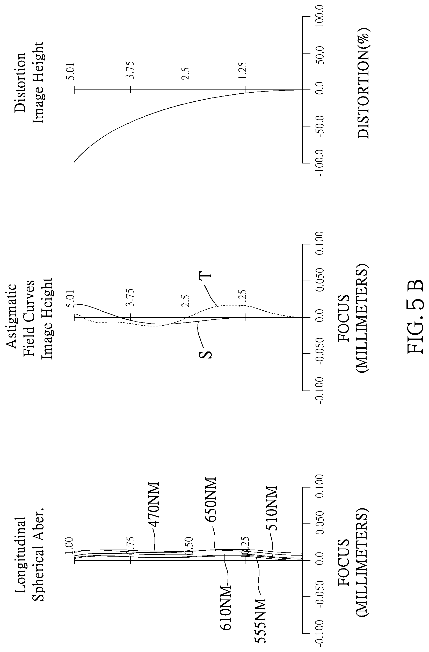
D00015
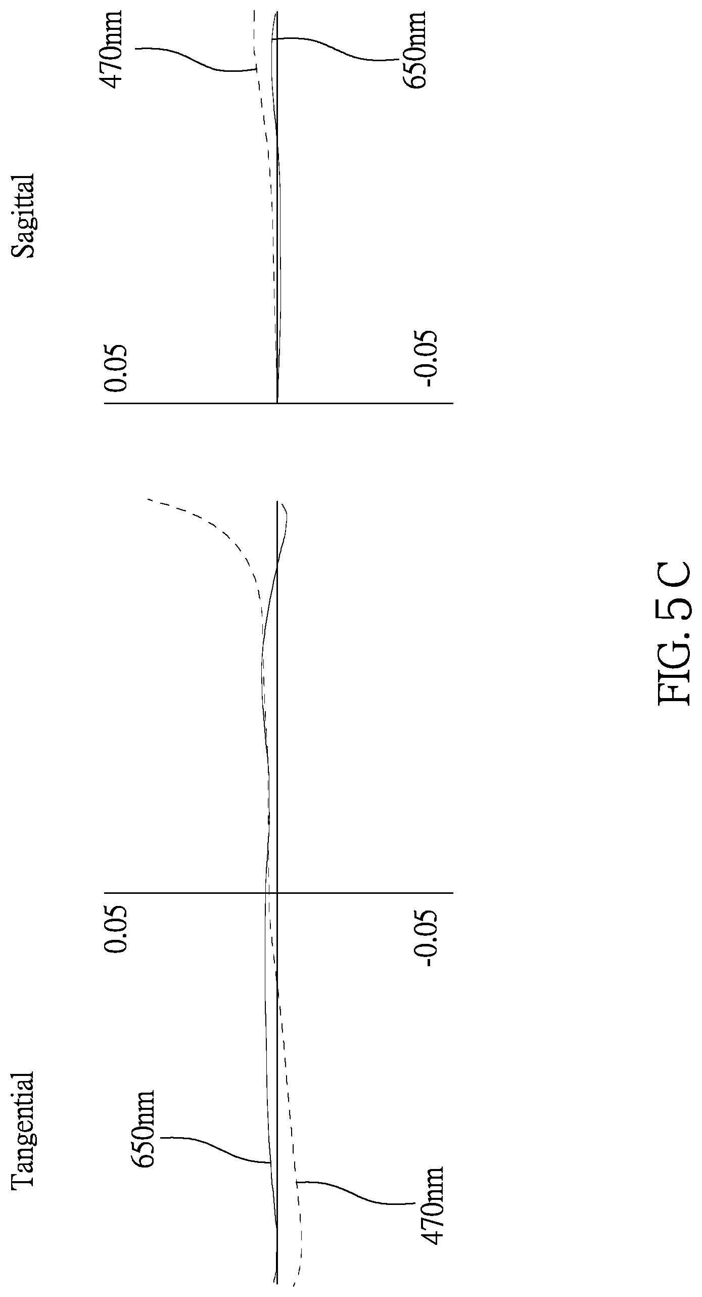
D00016

D00017

D00018
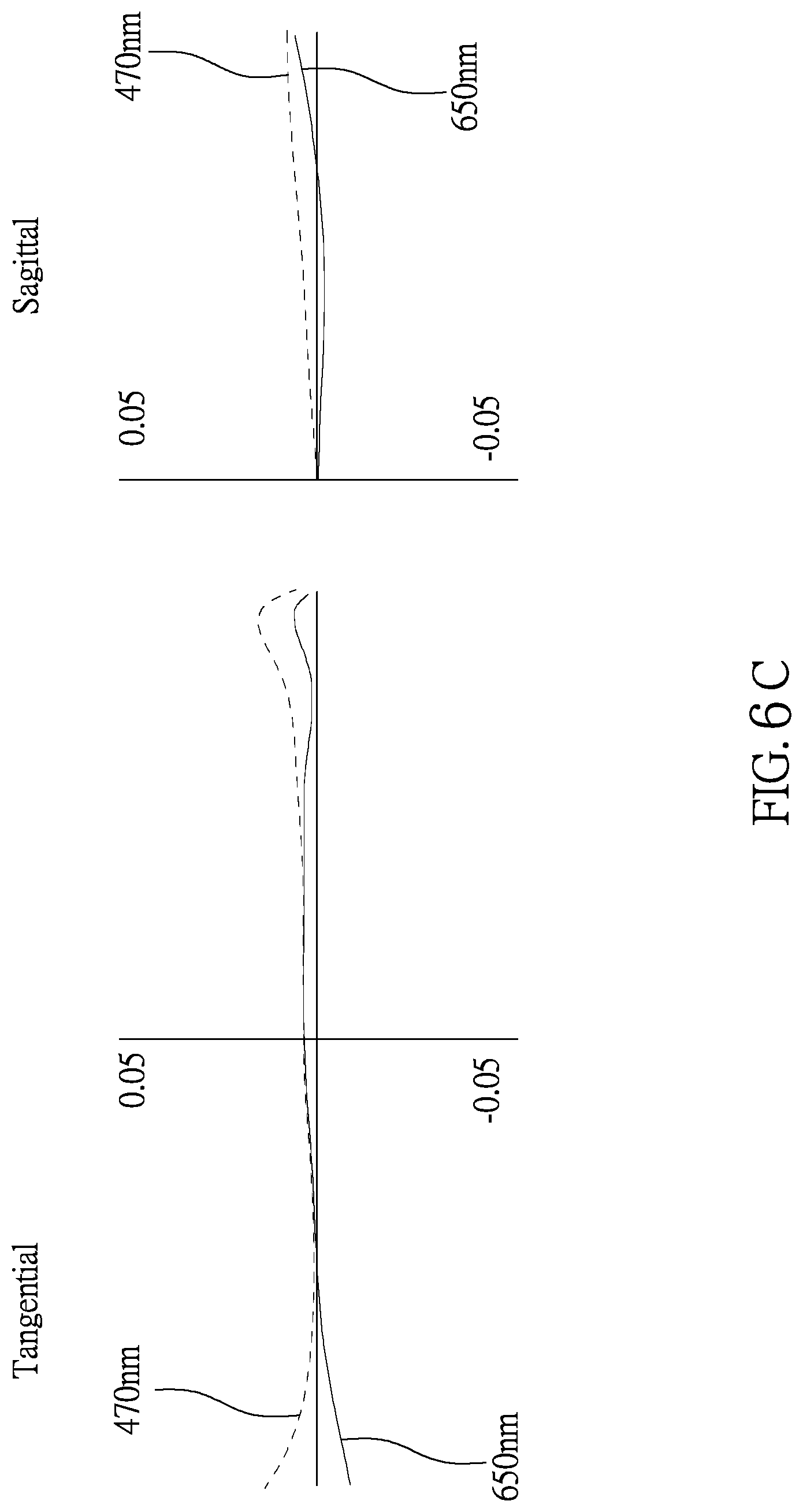
D00019

D00020

D00021

D00022
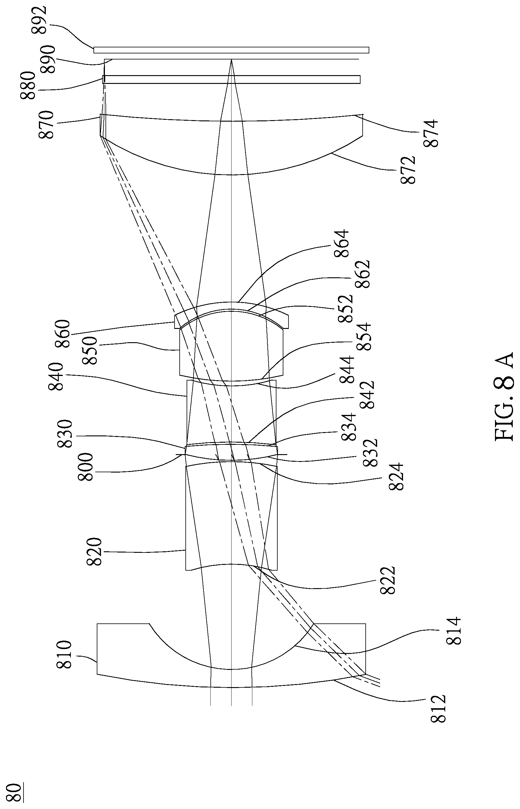
D00023

D00024
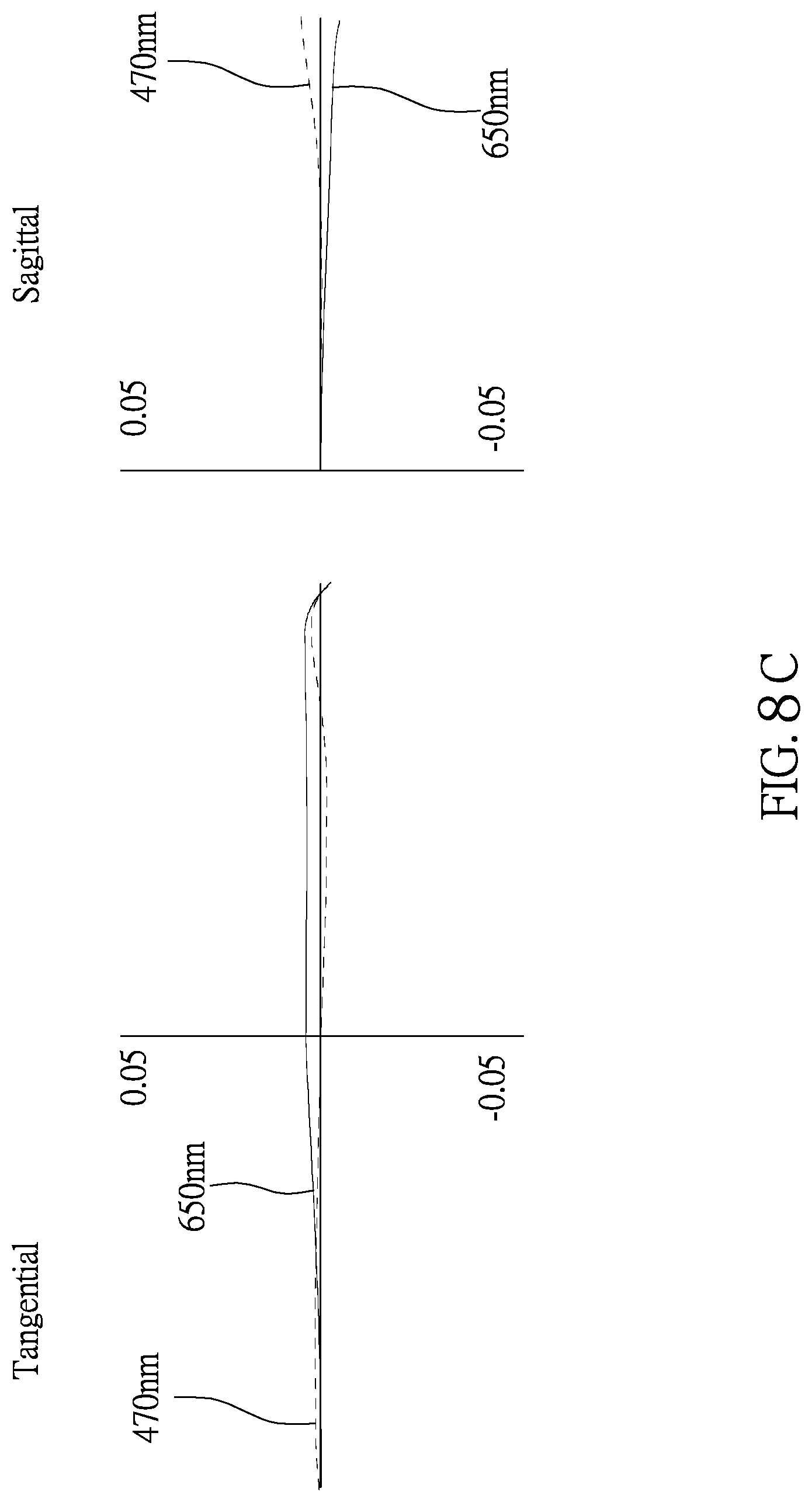
XML
uspto.report is an independent third-party trademark research tool that is not affiliated, endorsed, or sponsored by the United States Patent and Trademark Office (USPTO) or any other governmental organization. The information provided by uspto.report is based on publicly available data at the time of writing and is intended for informational purposes only.
While we strive to provide accurate and up-to-date information, we do not guarantee the accuracy, completeness, reliability, or suitability of the information displayed on this site. The use of this site is at your own risk. Any reliance you place on such information is therefore strictly at your own risk.
All official trademark data, including owner information, should be verified by visiting the official USPTO website at www.uspto.gov. This site is not intended to replace professional legal advice and should not be used as a substitute for consulting with a legal professional who is knowledgeable about trademark law.