Fiber optic payout assembly including cable spool
Kowalczyk , et al.
U.S. patent number 10,606,015 [Application Number 16/153,421] was granted by the patent office on 2020-03-31 for fiber optic payout assembly including cable spool. This patent grant is currently assigned to CommScope Technologies LLC. The grantee listed for this patent is CommScope Technologies LLC. Invention is credited to Jonathan Walter Coan, Jonathan R. Kaml, Scott C. Kowalczyk.


View All Diagrams
| United States Patent | 10,606,015 |
| Kowalczyk , et al. | March 31, 2020 |
Fiber optic payout assembly including cable spool
Abstract
A fiber optic enclosure assembly includes a housing having an interior region and a bearing mount disposed in the interior region of the housing. A cable spool is connectedly engaged with the bearing mount such that the cable spool selectively rotates within the housing. A termination module disposed on the cable spool so that the termination module rotates in unison with the cable spool. A method of paying out a fiber optic cable from a fiber optic enclosure includes rotating a cable spool, which has a subscriber cable coiled around a spooling portion of the cable spool, about an axis of a housing of the fiber optic enclosure until a desired length of subscriber cable is paid out. A termination module is disposed on the cable spool.
| Inventors: | Kowalczyk; Scott C. (Savage, MN), Coan; Jonathan Walter (Savage, MN), Kaml; Jonathan R. (Shakopee, MN) | ||||||||||
|---|---|---|---|---|---|---|---|---|---|---|---|
| Applicant: |
|
||||||||||
| Assignee: | CommScope Technologies LLC
(Hickory, NC) |
||||||||||
| Family ID: | 40454555 | ||||||||||
| Appl. No.: | 16/153,421 | ||||||||||
| Filed: | October 5, 2018 |
Prior Publication Data
| Document Identifier | Publication Date | |
|---|---|---|
| US 20190041598 A1 | Feb 7, 2019 | |
Related U.S. Patent Documents
| Application Number | Filing Date | Patent Number | Issue Date | ||
|---|---|---|---|---|---|
| 15875605 | Jan 19, 2018 | ||||
| 15470311 | Mar 27, 2017 | ||||
| 14979870 | Mar 28, 2017 | 9606319 | |||
| 14539459 | Feb 16, 2016 | 9261666 | |||
| 14132691 | Nov 18, 2014 | 8891931 | |||
| 13924191 | Apr 22, 2014 | 8705929 | |||
| 13479015 | Jul 23, 2013 | 8494333 | |||
| 13032337 | May 29, 2012 | 8189984 | |||
| 12793556 | Feb 22, 2011 | 7894701 | |||
| 12182705 | Jul 13, 2010 | 7756379 | |||
| 61029248 | Feb 15, 2008 | ||||
| 60954214 | Aug 6, 2007 | ||||
| Current U.S. Class: | 1/1 |
| Current CPC Class: | G02B 6/4446 (20130101); G02B 6/4454 (20130101); G02B 6/445 (20130101); G02B 6/4453 (20130101); G02B 6/3897 (20130101); G02B 6/46 (20130101); G02B 6/4452 (20130101); G02B 6/4471 (20130101); G02B 6/4441 (20130101); G02B 6/4457 (20130101) |
| Current International Class: | G02B 6/44 (20060101); G02B 6/46 (20060101); G02B 6/38 (20060101) |
References Cited [Referenced By]
U.S. Patent Documents
| 1276825 | August 1918 | Swope |
| 1442999 | January 1923 | Boyle |
| 1446410 | February 1923 | Bennett et al. |
| 1474580 | November 1923 | Clark et al. |
| RE20995 | February 1939 | Beasley |
| 2282156 | May 1942 | Benes |
| 2502496 | April 1950 | Wickman |
| 2521226 | September 1950 | Keller |
| 2727703 | December 1955 | Bonnett |
| 2767426 | October 1956 | Grupp |
| 3131729 | May 1964 | Leysinger |
| 3346705 | October 1967 | Slinkard et al. |
| 3433579 | March 1969 | Runnion |
| 3612424 | October 1971 | Friedel |
| 3657491 | April 1972 | Ryder et al. |
| 3667417 | June 1972 | Clinkenbeard |
| 3837448 | September 1974 | Hagstrom |
| 3920308 | November 1975 | Murray |
| 3940086 | February 1976 | Stoqulet |
| 3983977 | October 1976 | Crabb |
| 4053118 | October 1977 | Aikins |
| 4081258 | March 1978 | Goell et al. |
| 4143746 | March 1979 | Lowery |
| 4201278 | May 1980 | Balde |
| 4379615 | April 1983 | Toda et al. |
| 4384688 | May 1983 | Smith |
| 4470558 | September 1984 | Stamper |
| 4520239 | May 1985 | Schwartz |
| 4587801 | May 1986 | Missout et al. |
| 4635875 | January 1987 | Apple |
| 4657140 | April 1987 | Zagar et al. |
| 4666237 | May 1987 | Mallinson |
| 4767073 | August 1988 | Malzacher |
| 4869437 | September 1989 | Berz et al. |
| 4883337 | November 1989 | Dahlgren |
| 4913369 | April 1990 | Lia et al. |
| 4939798 | July 1990 | Last |
| 4940859 | July 1990 | Peterson |
| 4953194 | August 1990 | Hansen et al. |
| 4953810 | September 1990 | Stadig |
| 4968929 | November 1990 | Hauck et al. |
| 4978310 | December 1990 | Shichida |
| 5016554 | May 1991 | Harris, Jr. et al. |
| 5052940 | October 1991 | Bengal |
| 5066149 | November 1991 | Wheeler et al. |
| 5066256 | November 1991 | Ward, Sr. |
| 5069523 | December 1991 | Finzel et al. |
| 5071211 | December 1991 | Debortoli et al. |
| 5074863 | December 1991 | Dines |
| 5100221 | March 1992 | Carney et al. |
| 5107532 | April 1992 | Hansen et al. |
| 5124606 | June 1992 | Eisenbeis |
| 5161988 | November 1992 | Krupka |
| 5166970 | November 1992 | Ward |
| 5167001 | November 1992 | Debortoli et al. |
| 5172841 | December 1992 | Friedman |
| 5185843 | February 1993 | Aberson et al. |
| 5222164 | June 1993 | Bass, Sr. et al. |
| 5246377 | September 1993 | Kawahara et al. |
| 5265187 | November 1993 | Morin et al. |
| 5265815 | November 1993 | Soyka et al. |
| 5280861 | January 1994 | Corriveau |
| 5305405 | April 1994 | Emmons et al. |
| 5310356 | May 1994 | Obata et al. |
| 5317663 | May 1994 | Beard et al. |
| 5326040 | July 1994 | Kramer |
| 5335874 | August 1994 | Shrum et al. |
| 5353367 | October 1994 | Czosnowski et al. |
| 5393249 | February 1995 | Morgenstern et al. |
| 5394503 | February 1995 | Dietz, Jr. et al. |
| 5413494 | May 1995 | Dewey et al. |
| 5418334 | May 1995 | Williams |
| 5419717 | May 1995 | Abendschein et al. |
| 5434944 | July 1995 | Kerry et al. |
| 5448015 | September 1995 | Jamet et al. |
| 5448675 | September 1995 | Leone et al. |
| 5467062 | November 1995 | Burroughs et al. |
| 5473715 | December 1995 | Schofield et al. |
| 5483467 | January 1996 | Krupka et al. |
| 5490229 | February 1996 | Ghandeharizadeh et al. |
| 5494234 | February 1996 | Kramer |
| 5494446 | February 1996 | DeLucia et al. |
| 5497444 | March 1996 | Wheeler |
| 5519275 | May 1996 | Scott et al. |
| 5522561 | June 1996 | Koyamatsu et al. |
| 5528453 | June 1996 | Berman et al. |
| 5544836 | August 1996 | Pera |
| 5551545 | September 1996 | Gelfman |
| 5613030 | March 1997 | Hoffer et al. |
| 5638481 | June 1997 | Arnett |
| 5657412 | August 1997 | Caudrelier |
| 5685741 | November 1997 | Dewey et al. |
| 5703990 | December 1997 | Robertson et al. |
| 5709347 | January 1998 | Hoffmann et al. |
| 5712942 | January 1998 | Jennings et al. |
| 5717810 | February 1998 | Wheeler |
| 5718397 | February 1998 | Stevens |
| 5734774 | March 1998 | Morrell |
| 5749148 | May 1998 | White, III et al. |
| 5773757 | June 1998 | Kenney et al. |
| 5787219 | July 1998 | Mueller et al. |
| 5821510 | October 1998 | Cohen et al. |
| 5854824 | December 1998 | Bengal et al. |
| 5915640 | June 1999 | Wagter et al. |
| 5957401 | September 1999 | O'Donnell |
| 5987203 | November 1999 | Abel et al. |
| 5987207 | November 1999 | Hoke |
| 5992787 | November 1999 | Burke |
| 6002331 | December 1999 | Laor |
| 6035032 | March 2000 | Daoud |
| 6077108 | June 2000 | Lorscheider et al. |
| 6095837 | August 2000 | David et al. |
| 6116961 | September 2000 | Henneberger et al. |
| 6135254 | October 2000 | Liao |
| 6176559 | January 2001 | Tiramani et al. |
| 6195494 | February 2001 | Abbott et al. |
| 6215938 | April 2001 | Reitmeier et al. |
| 6220413 | April 2001 | Walters et al. |
| 6220762 | April 2001 | Kanai et al. |
| 6222908 | April 2001 | Bartolutti et al. |
| 6222975 | April 2001 | Gilbert et al. |
| 6223675 | May 2001 | Watt et al. |
| 6234830 | May 2001 | Ensz et al. |
| 6238235 | May 2001 | Shavit et al. |
| 6285293 | September 2001 | German et al. |
| 6286777 | September 2001 | Black |
| 6300877 | October 2001 | Schannach et al. |
| 6315598 | November 2001 | Elliot et al. |
| 6330148 | December 2001 | Won et al. |
| 6330307 | December 2001 | Bloch et al. |
| 6349893 | February 2002 | Daoud |
| 6350148 | February 2002 | Bartolutti et al. |
| 6361360 | March 2002 | Hwang et al. |
| 6367347 | April 2002 | Blaschke et al. |
| 6419175 | July 2002 | Rankin, VI |
| 6421322 | July 2002 | Koziy et al. |
| 6424710 | July 2002 | Bartolutti et al. |
| 6427045 | July 2002 | Matthes et al. |
| 6427781 | August 2002 | Buhler et al. |
| 6433274 | August 2002 | Doss et al. |
| 6456768 | September 2002 | Boncek et al. |
| D466479 | December 2002 | Pein et al. |
| 6494396 | December 2002 | Sugata |
| 6499861 | December 2002 | German et al. |
| 6511009 | January 2003 | Harrison et al. |
| 6511231 | January 2003 | Lampert et al. |
| 6522737 | February 2003 | Bartolutti et al. |
| 6522826 | February 2003 | Gregory |
| 6533205 | March 2003 | Kles |
| 6533216 | March 2003 | Bumgarner et al. |
| 6554221 | April 2003 | Hinds |
| 6554484 | April 2003 | Lampert |
| 6574586 | June 2003 | David et al. |
| 6591051 | July 2003 | Solheid et al. |
| 6616080 | September 2003 | Edwards et al. |
| 6626697 | September 2003 | Martin et al. |
| 6636152 | October 2003 | Schannach et al. |
| 6643443 | November 2003 | Holman et al. |
| 6669129 | December 2003 | Shah |
| 6684179 | January 2004 | David |
| 6702077 | March 2004 | Skowronski |
| 6711339 | March 2004 | Puetz et al. |
| 6715619 | April 2004 | Kim et al. |
| 6721484 | April 2004 | Blankenship et al. |
| 6725177 | April 2004 | David et al. |
| 6743044 | June 2004 | Musolf et al. |
| 6745971 | June 2004 | Renzoni |
| 6758314 | July 2004 | Woodruff |
| 6760530 | July 2004 | Mandry |
| 6793408 | September 2004 | Levy et al. |
| 6795633 | September 2004 | Joseph, II |
| 6819854 | September 2004 | Young et al. |
| 6802735 | October 2004 | Pepe et al. |
| 6808116 | October 2004 | Eslambolchi et al. |
| 6814624 | November 2004 | Clark et al. |
| 6834517 | December 2004 | Sheehy, Jr. |
| 6845207 | January 2005 | Schray |
| 6850685 | February 2005 | Tinucci et al. |
| 6856748 | February 2005 | Elkins, II et al. |
| 6885799 | April 2005 | Lee |
| 6889701 | May 2005 | Kovacik et al. |
| 6898368 | May 2005 | Colombo et al. |
| 6901200 | May 2005 | Schray |
| 6905363 | June 2005 | Musolf et al. |
| 6915058 | July 2005 | Pons |
| 6932517 | August 2005 | Swayze et al. |
| 6933441 | August 2005 | Fuller et al. |
| 6937725 | August 2005 | Liao |
| D510068 | September 2005 | Haggay et al. |
| 6944387 | September 2005 | Howell et al. |
| 6948680 | September 2005 | Ganster |
| 6961675 | November 2005 | David |
| 6971895 | December 2005 | Sago et al. |
| 6976867 | December 2005 | Navarro et al. |
| 6997410 | February 2006 | Huang |
| 7000863 | February 2006 | Bethea et al. |
| 7011538 | March 2006 | Chang |
| 7016590 | March 2006 | Tanaka et al. |
| 7017721 | March 2006 | Bradford et al. |
| 7027704 | April 2006 | Frohlich et al. |
| 7036601 | May 2006 | Berg et al. |
| 7050041 | May 2006 | Smith et al. |
| 7052281 | May 2006 | Meyberg et al. |
| 7065282 | June 2006 | Sasaki et al. |
| 7077710 | July 2006 | Haggay et al. |
| 7081808 | July 2006 | Colombo et al. |
| 7112090 | September 2006 | Caveney et al. |
| 7120349 | October 2006 | Elliott |
| 7123810 | October 2006 | Parrish |
| 7139461 | November 2006 | Puetz et al. |
| 7142764 | November 2006 | Allen et al. |
| 7153142 | December 2006 | Shifris et al. |
| 7165728 | January 2007 | Durrant et al. |
| 7193422 | March 2007 | Velleca et al. |
| 7210858 | May 2007 | Sago et al. |
| 7220144 | May 2007 | Elliot et al. |
| 7226217 | June 2007 | Benton et al. |
| 7234944 | June 2007 | Nordin et al. |
| 7297018 | November 2007 | Caveney et al. |
| 7306101 | December 2007 | Murry |
| 7312715 | December 2007 | Shalts et al. |
| D559186 | January 2008 | Kelmer |
| 7315224 | January 2008 | Gurovich et al. |
| 7315681 | January 2008 | Kewitsch |
| 7346253 | March 2008 | Bloodsworth et al. |
| 7352289 | April 2008 | Harris |
| 7364108 | April 2008 | Kim et al. |
| 7369739 | May 2008 | Kline et al. |
| 7370106 | May 2008 | Caveney |
| 7397997 | July 2008 | Ferris et al. |
| 7400814 | July 2008 | Hendrickson et al. |
| 7406242 | July 2008 | Braga |
| 7477829 | January 2009 | Kaplan |
| 7479032 | January 2009 | Hoath et al. |
| 7493003 | February 2009 | Kowalczyk |
| 7519000 | April 2009 | Caveney et al. |
| 7522806 | April 2009 | Hendrickson et al. |
| 7533841 | May 2009 | Harrison et al. |
| 7534137 | May 2009 | Caveney et al. |
| 7546018 | June 2009 | Hendrickson et al. |
| 7552872 | June 2009 | Tokita et al. |
| 7570861 | August 2009 | Smrha et al. |
| 7591667 | September 2009 | Gatnau Navarro et al. |
| 7676136 | March 2010 | Wakileh et al. |
| 7697811 | April 2010 | Murano et al. |
| 7711233 | May 2010 | Mahoney |
| 7715679 | May 2010 | Kowalczyk et al. |
| 7751672 | July 2010 | Smith et al. |
| 7756379 | July 2010 | Kowalczyk et al. |
| 7809234 | October 2010 | Smith et al. |
| 7811119 | October 2010 | Caveney et al. |
| 7869426 | January 2011 | Hough et al. |
| 7869682 | January 2011 | Kowalczyk et al. |
| 7872738 | January 2011 | Abbott |
| 7885505 | February 2011 | Zimmel |
| 7894701 | February 2011 | Kowalczyk et al. |
| 8081857 | December 2011 | Nair et al. |
| 8131126 | March 2012 | Kowalczyk et al. |
| 8157582 | April 2012 | Frey et al. |
| 8189984 | May 2012 | Kowalczyk et al. |
| 8229267 | July 2012 | Kowalczyk et al. |
| 8254740 | August 2012 | Smith et al. |
| 8265447 | September 2012 | Loeffelholz et al. |
| 8326107 | December 2012 | Cooke et al. |
| 8380035 | February 2013 | Kowalczyk et al. |
| 8422847 | April 2013 | Kowalczyk et al. |
| 8428419 | April 2013 | LeBlanc |
| 8494333 | July 2013 | Kowalczyk et al. |
| 8494334 | July 2013 | Kowalczyk et al. |
| 8565572 | October 2013 | Krampotich |
| 8705929 | April 2014 | Kowalczyk |
| 8774588 | July 2014 | Kowalczyk |
| 8818157 | August 2014 | Burek et al. |
| RE45153 | September 2014 | Hendrickson et al. |
| 8891931 | November 2014 | Kowalczyk |
| 8929706 | January 2015 | Teymouri |
| 8938147 | January 2015 | Krampotich et al. |
| 9097870 | August 2015 | Torman |
| 9170392 | October 2015 | Krampotich et al. |
| 9223103 | December 2015 | Kachmar |
| 9261663 | February 2016 | Loeffelholz et al. |
| 9261666 | February 2016 | Kowalczyk et al. |
| 9310578 | April 2016 | Vastmans et al. |
| 9341802 | May 2016 | Krampotich et al. |
| 9429728 | August 2016 | Puetz et al. |
| 9453971 | September 2016 | Anderson et al. |
| 9459424 | October 2016 | Smith |
| 9563032 | February 2017 | Kowalczyk |
| 9606319 | March 2017 | Kowalczyk et al. |
| 9618720 | April 2017 | Sayres |
| 9664871 | May 2017 | Galvan Mijangos |
| 9684142 | June 2017 | Collart |
| 9703063 | July 2017 | Van Baelen et al. |
| 9766414 | September 2017 | Marcouiller et al. |
| 9885846 | February 2018 | Kowalczyk et al. |
| 9995898 | June 2018 | Krampotich et al. |
| RE47307 | March 2019 | Allen |
| 10234648 | March 2019 | Kowalczyk et al. |
| 2001/0019002 | September 2001 | Walters et al. |
| 2001/0048044 | December 2001 | Sugata |
| 2002/0003186 | January 2002 | Hinds |
| 2002/0023814 | February 2002 | Poutiatine |
| 2002/0023984 | February 2002 | Oppmann et al. |
| 2002/0083538 | July 2002 | Silverman et al. |
| 2002/0126980 | September 2002 | Holman et al. |
| 2002/0164121 | November 2002 | Brennan, III et al. |
| 2002/0171002 | November 2002 | Krestsch et al. |
| 2003/0037480 | February 2003 | Davis |
| 2003/0042348 | March 2003 | Salentine et al. |
| 2003/0142817 | July 2003 | Liao |
| 2003/0223724 | December 2003 | Puetz |
| 2003/0230667 | December 2003 | Ganster |
| 2004/0052498 | March 2004 | Colombo et al. |
| 2004/0065443 | April 2004 | Berg et al. |
| 2004/0084271 | May 2004 | Woodruff |
| 2004/0170369 | September 2004 | Pons |
| 2004/0200332 | October 2004 | Chen |
| 2004/0209505 | October 2004 | Wade et al. |
| 2004/0240807 | December 2004 | Frohlich et al. |
| 2004/0244430 | December 2004 | Sheehy, Jr. |
| 2004/0258384 | December 2004 | Trebesch et al. |
| 2005/0002633 | January 2005 | Solheid |
| 2005/0062881 | March 2005 | Caci et al. |
| 2005/0103515 | May 2005 | Fuller et al. |
| 2005/0128769 | June 2005 | Gozum et al. |
| 2005/0145522 | July 2005 | Bloodworth et al. |
| 2005/0184186 | August 2005 | Tsoi et al. |
| 2005/0185910 | August 2005 | Zimmel |
| 2005/0213920 | September 2005 | Tanaka et al. |
| 2005/0247136 | November 2005 | Cross et al. |
| 2005/0258203 | November 2005 | Weaver |
| 2005/0258411 | November 2005 | Zeitler |
| 2005/0277829 | December 2005 | Tsonton et al. |
| 2006/0028198 | February 2006 | Hoopengarner |
| 2006/0045458 | March 2006 | Sasaki et al. |
| 2006/0054760 | March 2006 | Murry |
| 2006/0148279 | July 2006 | German et al. |
| 2006/0153516 | July 2006 | Napiorkowski et al. |
| 2006/0160395 | July 2006 | Macauley et al. |
| 2006/0163403 | July 2006 | Dickson |
| 2006/0169856 | August 2006 | Dorenkamp et al. |
| 2006/0183362 | August 2006 | Mullaney et al. |
| 2006/0185953 | August 2006 | Gieseke |
| 2006/0186255 | August 2006 | Rooker |
| 2006/0187696 | August 2006 | Lanni |
| 2006/0210230 | September 2006 | Kline et al. |
| 2006/0231672 | October 2006 | Eastwood et al. |
| 2006/0264094 | November 2006 | Young |
| 2006/0266605 | November 2006 | Caamano et al. |
| 2006/0280418 | December 2006 | Mahoney |
| 2007/0023559 | February 2007 | Scapillato et al. |
| 2007/0025675 | February 2007 | Kramer |
| 2007/0036506 | February 2007 | Kewitsch |
| 2007/0096538 | May 2007 | Niemi et al. |
| 2007/0108333 | May 2007 | Kuramoto |
| 2007/0165995 | July 2007 | Reagan et al. |
| 2007/0176045 | August 2007 | Chen |
| 2007/0189691 | August 2007 | Barth et al. |
| 2007/0237470 | October 2007 | Aronson et al. |
| 2008/0011990 | January 2008 | Kostet et al. |
| 2008/0013893 | January 2008 | Zheng et al. |
| 2008/0013909 | January 2008 | Kostet et al. |
| 2008/0035778 | February 2008 | Belden et al. |
| 2008/0037945 | February 2008 | Gniadek et al. |
| 2008/0093187 | April 2008 | Roberts et al. |
| 2008/0100467 | May 2008 | Downie et al. |
| 2008/0116312 | May 2008 | Eastwood et al. |
| 2008/0170831 | July 2008 | Hendrickson et al. |
| 2008/0011514 | August 2008 | Zheng et al. |
| 2008/0199139 | August 2008 | Henderson |
| 2008/0218947 | September 2008 | Atkinson |
| 2008/0236209 | October 2008 | Conti et al. |
| 2008/0292261 | November 2008 | Kowalczyk et al. |
| 2008/0315030 | December 2008 | Hendrickson et al. |
| 2009/0057085 | March 2009 | Caamano et al. |
| 2009/0060441 | March 2009 | Kowalczyk et al. |
| 2009/0074370 | March 2009 | Kowalczyk |
| 2009/0097846 | April 2009 | Kozischek et al. |
| 2009/0098763 | April 2009 | Below et al. |
| 2009/0166404 | July 2009 | German et al. |
| 2009/0190894 | July 2009 | Nhep et al. |
| 2009/0215310 | August 2009 | Hoath et al. |
| 2009/0257726 | October 2009 | Redmann et al. |
| 2009/0317047 | December 2009 | Smith et al. |
| 2010/0054680 | March 2010 | Lochkovic et al. |
| 2010/0054682 | March 2010 | Cooke |
| 2010/0054684 | March 2010 | Cooke et al. |
| 2010/0074587 | March 2010 | Loeffelholz et al. |
| 2010/0090830 | April 2010 | Conti et al. |
| 2010/0166376 | July 2010 | Nair et al. |
| 2010/0211664 | August 2010 | Raza et al. |
| 2010/0211665 | August 2010 | Raza et al. |
| 2010/0211697 | August 2010 | Raza et al. |
| 2010/0215049 | August 2010 | Raza et al. |
| 2010/0322583 | December 2010 | Cooke et al. |
| 2011/0044599 | February 2011 | Kowalczyk et al. |
| 2011/0092100 | April 2011 | Coffey et al. |
| 2011/0094274 | April 2011 | Conti et al. |
| 2011/0103761 | May 2011 | LeBlanc et al. |
| 2011/0158598 | June 2011 | LeBlanc et al. |
| 2013/0094828 | April 2013 | Loeffelholz et al. |
| 2013/0170810 | July 2013 | Badar et al. |
| 2013/0170811 | July 2013 | Kowalczyk et al. |
| 2013/0242866 | September 2013 | Lin et al. |
| 2014/0010512 | January 2014 | Kowalczyk et al. |
| 2014/0010513 | January 2014 | Kowalczyk et al. |
| 2014/0219622 | August 2014 | Coan |
| 2015/0063770 | March 2015 | Kowalczyk et al. |
| 2015/0093088 | April 2015 | Matz et al. |
| 2017/0199344 | July 2017 | Kowalczyk et al. |
| 2017/0235079 | August 2017 | Kowalczyk et al. |
| 1799296 | Jul 2006 | CN | |||
| 42 26 368 | Feb 1994 | DE | |||
| 102 44 304 | Mar 2004 | DE | |||
| 1 107 031 | Jun 2001 | EP | |||
| 2 618 195 | Jul 2013 | EP | |||
| 2 566 997 | Jan 1986 | FR | |||
| 2 236 398 | Apr 1991 | GB | |||
| 1-123203 | May 1989 | JP | |||
| 9-236709 | Sep 1997 | JP | |||
| 11-87006 | Mar 1999 | JP | |||
| 11-349230 | Dec 1999 | JP | |||
| 2003-114339 | Apr 2003 | JP | |||
| 2005-73365 | Mar 2005 | JP | |||
| 2005-249858 | Sep 2005 | JP | |||
| 2007-121609 | May 2007 | JP | |||
| 2007121598 | May 2007 | JP | |||
| WO 2009/048680 | Apr 2009 | WO | |||
| WO 2010/001400 | Jan 2010 | WO | |||
| WO 2010/081186 | Jul 2010 | WO | |||
| WO 2010/121639 | Oct 2010 | WO | |||
Other References
|
7 Inch Modules, ADC Telecommunications, Inc, .COPYRGT. 1998, "7 Inch Connector Module with IFC", pp. 127. cited by applicant . Answer, CommScope Technologies LLC v. Clearfield, Inc., Case No. 0:17-cv-00307-PJS-BRT, 27 pages (Apr. 24, 2017). cited by applicant . Australian Examination Report for Application No. 2015205930; dated Jul. 13, 2016; 4 pages. cited by applicant . Australian Office Action (Appln. No. 2008247361), dated Nov. 8, 2013. cited by applicant . Avaya's Enhanced SYSTIMAX.RTM. iPatch System Enables IT Managers to Optimise Network Efficiency and Cut Downtime, Press Release, May 20, 2003, obtained from http://www.avaya.com/usa/about-avaya/newsroom/news-releases/2003/pr-03052- 0 on Jan. 7, 2009. cited by applicant . Description of Admitted Prior Art, 30 pages. cited by applicant . European Search Report for Application No. 13163032.9 dated Jul. 4, 2013. cited by applicant . European Search Report for Application No. 15182271.5 dated Dec. 2, 2015. cited by applicant . F3DF Modules, ADC Telecommunications, Inc. .COPYRGT. 1995, "Individual 12-Pack Assemblies", pp. 90. cited by applicant . Fiber Cable Management Products, Third Edition, ADC Telecommunications, Inc., .COPYRGT. 1995, 1998. cited by applicant . Fiber Distribution Frame, Pre-Terminated Rear Load Connector Module, Installation Instructions, ADC Telecommunications, Inc., .COPYRGT. 2000. cited by applicant . Fiber Main Distribution Frame (FMDF), Fiber Terminal Block, Installation Instructions, ADC Telecommunications, Inc., .COPYRGT. 2001. cited by applicant . Fiber Panel Products--Cable Management Tray Panels, ADC Telecommunications, Inc., .COPYRGT. 1994, 1996 "72 Fiber Distribution Module (FDM) with Intrafacility Fiber Cable", pp. 56. cited by applicant . Fiber Panel Products, Second Edition, ADC Telecommunications, Inc., .COPYRGT. 1994, 1996. cited by applicant . FL2000 Products--Preconfigured Panels, ADC Telecommunications, Inc., .COPYRGT. 2000 "Rack or Cabinet Mount Termination Panel with Multifiber Cable", pp. 13. cited by applicant . FL2000 Products, ADC Telecommunications, Inc., .COPYRGT. 1994, 1996. cited by applicant . FL2000 Products, ADC Telecommunications, Inc., .COPYRGT. 1994, 1996, "Rack Mount Panel with Intrafacility Fiber Cable", pp. 16. cited by applicant . IFC Style Frame Modules, ADC Telecommunications, Inc., .COPYRGT. 1995, "Connector Module Equipped with IFC", pp. 27. cited by applicant . Intelligent patching systems carving out a `large` niche, Cabling Installation & Maintenance, vol. 12, Issue 7, Jul. 2004 (5 pages). cited by applicant . IntelliMAC: The intelligent way to make Moves, Adds or Changes! NORDX/CDT .COPYRGT.2003 (6 pages). cited by applicant . International Search Report and Written Opinion for PCT/US2008/062764 dated Aug. 8, 2008. cited by applicant . International Search Report and Written Opinion for PCT/US2008/075196 dated Nov. 18, 2008. cited by applicant . International Search Report and Written Opinion for PCT/US2008/072218 dated Mar. 18, 2009. cited by applicant . International Search Report and Written Opinion for PCT/US2010/052872 dated Jan. 12, 2011. cited by applicant . International Search Report and Written Opinion for PCT/US2011/041605 dated Feb. 24, 2012. cited by applicant . Meredith, L., "Managers missing point of intelligent patching," Daa Center News, Jun. 21, 2005, obtained Dec. 2, 2008 from http://searchdatacenter.techtarget.com/news/article/0,289142,sid80_gci109- 9991,00.html. cited by applicant . Next Generation Frame (NGF), Product Family Ordering Guide, ADC Telecommunications, Inc., .COPYRGT. 1996, 1999, 2000, "Fiber Termination Blocks (FTB) Preterminated", pp. 8. cited by applicant . Next Generation Frame (NGF), Product Family Ordering Guide, ADC Telecommunications, Inc., .COPYRGT. 1996, 1999, 2000. cited by applicant . Next Generation Frames--Fiber Termination Blocks, ADC Telecommunication, Inc., .COPYRGT. 1998, "Fiber Termination Blocks (FTB) Preterminated" pp. 6. cited by applicant . Notice of Allowance for U.S. Appl. No. 13/924,191 dated Dec. 3, 2013. cited by applicant . Ohtsuki, F. et al., "Design of Optical Connectors with ID Modules," Electronics and Communications in Japan, Part 1, vol. 77, No. 2, pp. 94-105 (Feb. 1994). cited by applicant . Supplemental Notice of Allowability for U.S. Appl. No. 13/924,191 dated Mar. 10, 2014. cited by applicant . Supplemental Notice of Allowability for U.S. Appl. No. 13/924,191 dated Mar. 14, 2014. cited by applicant . SYSTIMAX.RTM. iPatch System Wins Platinum Network of the Year Award, Press Release, Jan. 30, 2003, obtained from http://www.avaya.com/usa/about-avaya/newsroom/news-releases/2003/pr-03013- 0a on Jan. 7, 2009. cited by applicant . TrueNet; TFP Series Rack Mount Fiber Panels, Spec Sheet; May 2008; 8 pages. cited by applicant . Value-Added Module System, ADC Telecommunications, Inc., .COPYRGT. 1993, 1194, 1998, "12-Pack Module Assemblies", pp. 30-31. cited by applicant . Complaint relating to Civil Action No. 5:11-cv-02509-JS, ADC Telecommunications, Inc v. Opterna Am, Inc. filed Apr. 11, 2011 (14 pages). cited by applicant . Plaintiff's Notice of Dismissal relating to Civil Action No. 5:11-cv-02509-JS, ADC Telecommunications, Inc v. Opterna Am, Inc. filed Jul. 12, 2011 (1 page). cited by applicant . Complaint relating to Civil Action No. 1:11cv-735 (GBL-IDD), ADC Telecommunications, Inc v. Opterna Am, Inc. filed Jul. 12, 2011 (5 pages). cited by applicant . Complaint, CommScope Technologies LLC v. Clearfield, Inc., Case No. 0:17-cv-00307, 77 pages (Jan. 31, 2017). cited by applicant . Complaint Exhibit G, CommScope Technologies LLC v. Clearfield, Inc., Case No. 0:17-cv-00307-PJS-BRT, 3 pages (Jan. 31, 2017) . cited by applicant . Complaint Exhibit H, CommScope Technologies LLC v. Clearfield, Inc., Case No. 0:17-cv-00307-PJS-BRT, 3 pages (Jan. 31, 2017). cited by applicant . Defendant Clearfield Inc. 's Preliminary Invalidity Claim Charts and Disclosures, CommScope Technologies LLC v. Clearfield, Inc., Case No. 0:17-cv-00307-PJS-BRT, 62 pages (Oct. 6, 2017). cited by applicant . Defendant Clearfield Inc. 's Invalidity Claim Chart Exhibit 10, CommScope Technologies LLC v. Clearfield, Inc., Case No. 0:17-cv-00307-PJS-BRT, 36 pages (Oct. 6, 2017). cited by applicant . Defendant Clearfield Inc. 's Invalidity Claim Chart Exhibit 11, CommScope Technologies LLC v. Clearfield, Inc., Case No. 0:17-cv-00307-PJS-BRT, 60 pages (Oct. 6, 2017). cited by applicant . Defendant Clearfield Inc. 's Invalidity Claim Chart Table D, CommScope Technologies LLC v. Clearfield, Inc., Case No. 0:17-cv-00307-PJS-BRT, 7 pages (Oct. 6, 2017). cited by applicant . Defendant Clearfield Inc. 's Invalidity Claim Chart Table E, CommScope Technologies LLC v. Clearfield, Inc., Case No. 0:17-cv-00307-PJS-BRT, 7 pages (Oct. 6, 2017). cited by applicant . Plantiff CommScope Technologies LLC's Memorandum in Support of Motion to Compel Discovery, CommScope Technologies LLC v. Clearfield, Inc., Case No. 0:17-cv-00307-PJS-BRT, 21 pages (Oct. 9, 2017). cited by applicant . Plaintiff CommScope Technologies LLC's Response to Defendant's First Set of Interrogatories to Plaintiff (Nos. 1-15), CommScope Technologies LLC v. Clearfield, Inc., Case No. 0:17-cv-00307-PJS-BRT, 26 pages (Oct. 9, 2017) cited by applicant . Plaintiff CommScope Technologies LLC's Supplemental Response to Defendant's Interrogatory No. 2, CommScope Technologies LLC v. Clearfield, Inc., Case No. 0:17-cv-00307-PJS-BRT, 5 pages (Oct. 9, 2017) cited by applicant . Plantiff CommScope'Initial Claim Charts including Exhibits J and K, CommScope Technologies LLC v. Clearfield, Inc., Case No. 0:17-cv-00307-PJS-BRT, 28 pages (Oct. 9, 2017). cited by applicant . Defendant Clearfield Inc. 's Revised Preliminary Invalidity Claim Charts and Disclosures, Civil Action No. 17-cv-00307-PJS-BRT, 51 pages (Dec. 11, 2017) cited by applicant . Defendant Clearfield Inc. 's Revised Invalidity Claim Chart Exhibit 10, CommScope Technologies LLC v. Clearfield, Inc., Case No. 0:17-cv-00307-PJS-BRT, 38 pages (Dec. 11, 2017) cited by applicant . Defendant Clearfield Inc. 's Revised Invalidity Claim Chart Exhibit 11, CommScope Technologies LLC v. Clearfield, Inc., Case No. 0:17-cv-00307-PJS-BRT, 39 pages (Dec. 11, 2017) cited by applicant . Defendant Clearfield Inc. 's Revised Invalidity Claim Chart Table D, CommScope Technologies LLC v. Clearfield, Inc., Case No. 0:17-cv-00307-PJS-BRT, 7 pages (Dec. 11, 2017). cited by applicant . Defendant Clearfield Inc. 's Revised Invalidity Claim Chart Table E, CommScope Technologies LLC v. Clearfield, Inc., Case No. 0:17-cv-00307-PJS-BRT, 6 pages (Dec. 11, 2017). cited by applicant . Defendant Clearfield Inc. 's Second Revised Preliminary Invalidity Claim Charts and Disclosures, Civil Action No. 17-cv-00307-PJS-BRT, 65 pages (Jan. 12, 2018) cited by applicant . Exhibit 10 to Second Revised Preliminary Invalidity Claim Charts and Disclosures, Civil Action No. 17-cv-00307-PJS-BRT, 43 pages (Jan. 12, 2018). cited by applicant . Exhibit 11 to Second Revised Preliminary Invalidity Claim Charts and Disclosures, Civil Action No. 17-00307-PJS-BRT, 47 pages (Jan. 12, 2018). cited by applicant . Commscope's Response to Clearfield's Second Revised Invalidity Claim Charts and Disclosure, Civil Action No. 17-CV-00307-PJS-BRT, 105 pages (Jan. 19, 2018) cited by applicant . Exhibit J to Second Revised Preliminary Invalidity Claim Charts and Disclosures, Civil Action No. 17-cv-00307-PJS-BRT, 21 pages (Jan. 19, 2018). cited by applicant . Exhibit K to Second Revised Preliminary Invalidity Claim Charts and Disclosures, Civil Action No. 17-cv-00307-PJS-BRT, 19 pages (Jan. 19, 2018). cited by applicant . Joint Status Report, CommScope Technologies LLC v. Clearfield, Inc., Case No. 0:17-cv-00307-PJS-BRT, 11 pages (Feb. 9, 2018. cited by applicant . Joint Status Report Exhibit A, CommScope Technologies LLC v. Clearfield, Inc., Case No. 0:17-cv-00307-PJS-BRT, 33 pages (Feb. 9, 2018). cited by applicant . Joint Status Report Exhibit B, CommScope Technologies LLC v. Clearfield, Inc., Case No. 0:17-cv-00307-PJS-BRT, 21 pages (Feb. 9, 2018). cited by applicant . Stipulation of Dismissal, CommScope Technologies LLC v. Clearfield, Inc., Case No. 0:17-cv-00307-PJS-BRT, 2 pages (Feb. 19, 2018). cited by applicant . Order of Dismissal, CommScope Technologies LLC v. Clearfield, Inc., Case No. 0:17-cv-00307-PJS-BRT, 1 page (Feb. 20, 2018). cited by applicant . Petition for Inter Partes Review of U.S. Pat. No. 8,705,929, Clearfield Inc. v. CommScope Technologies LLC, Case No. IPR2017-02122, 67 pages (Sep. 15, 2017). cited by applicant . Inter Partes Review Case No. IPR2017-02122, Ex. 1003--Declaration of Dr. Michael Lebby, 141 pages (Sep. 15, 2017). cited by applicant . Inter Partes Review Case No. IPR2017-02122, Ex. 1004--U.S. Pat. No. 6,220,413 B1. cited by applicant . Inter Partes Review Case No. IPR2017-02122, Ex. 1005--U.S. Pat. No. 6,933,441 B2. cited by applicant . Inter Partes Review Case No. IPR2017-02122, Ex. 1006--U.S. Pat. No. 4,201,278. cited by applicant . Inter Partes Review Case No. IPR2017-02122, Ex. 1007--Prosecution History of U.S. Appl. No. 12/182,705, filed Jul. 30, 2008., 332 pages. cited by applicant . Inter Partes Review Case No. IPR2017-02122, Ex. 1008--PCT Patent No. WO 2009/048680 A1. cited by applicant . Inter Partes Review Case No. IPR2017-02122, Ex. 1009--European Patent No. 2 618 195 A2. cited by applicant . Inter Partes Review Case No. IPR2017-02122, Ex. 1010--File Wrapper of EP App. No. 13163032.9, downloaded from European Patent Office on Aug. 10, 2017, 222 pages. cited by applicant . Inter Partes Review Case No. IPR2017-02122, Ex. 1011--U.S. Pat. No. 4,657,140. cited by applicant . Inter Partes Review Case No. IPR2017-02122, Ex. 1012--USConec MTP.RTM. Brand Connectors Data Sheet (.COPYRGT. 2014), 2 pages. cited by applicant . Inter Partes Review Case No. IPR2017-02122, Ex. 1013--Katsuki Suematsu et al., "Super Low-Loss, Super High-Density Multi-Fiber Optical Connectors," Furukawa Review (n. 23), 2003 ("Suematsu"). cited by applicant . Inter Partes Review Case No. IPR2017-02122, Ex. 1014--U.S. Pat. No. 6,885,799 B2. cited by applicant . Preliminary Response by Patent Owner Under 37 C.F.R. .sctn. 42.107, Case IPR2017-02122, Paper No. 6, 71 pages (Dec. 22, 2017). cited by applicant . Ex. 2001--Declaration of Casimer DeCusatis in Support of Patent Owner's Preliminary Response, Case IPR2017-02122. cited by applicant . Ex. 2002--Office Action dated Jun. 19, 2009 in connection with U.S. Appl. No. 12/182,705. cited by applicant . Ex. 2003--Response to Jun. 19, 2009 Office Action in connection with U.S. Appl. No. 12/182,705. cited by applicant . Ex. 2004--U.S. Patent Application Publication No. 2006/021 0230 ("Kline"). cited by applicant . Ex. 2005--Excerpts from the Merriam-Webster's Collegiate Dictionary (Tenth Edition) (2000). cited by applicant . Ex. 2006--Excerpts from the New Oxford American Dictionary (Third Edition) (2010). cited by applicant. |
Primary Examiner: Ullah; Akm E
Attorney, Agent or Firm: Merchant & Gould P.C.
Parent Case Text
CROSS-REFERENCE TO RELATED APPLICATIONS
This application is a continuation of application Ser. No. 15/875,605, filed Jan. 19, 2018, which is a continuation of application Ser. No. 15/470,311, filed Mar. 27, 2017, which is a continuation of application Ser. No. 14/979,870, filed Dec. 28, 2015, now U.S. Pat. No. 9,606,319, which is a continuation of application Ser. No. 14/539,459, filed Nov. 12, 2014, now U.S. Pat. No. 9,261,666, which is a continuation of application Ser. No. 14/132,691, filed Dec. 18, 2013, now U.S. Pat. No. 8,891,931, which is a continuation of application Ser. No. 13/924,191, filed Jun. 21, 2013, now U.S. Pat. No. 8,705,929, which is a continuation of application Ser. No. 13/479,015, filed May 23, 2012, now U.S. Pat. No. 8,494,333, which is a continuation of application Ser. No. 13/032,337, filed Feb. 22, 2011, now U.S. Pat. No. 8,189,984, which is a continuation of application Ser. No. 12/793,556, filed Jun. 3, 2010, now U.S. Pat. No. 7,894,701, which is a continuation of application Ser. No. 12/182,705, filed Jul. 30, 2008, now U.S. Pat. No. 7,756,379, which application claims the benefit of provisional application Ser. Nos. 61/029,248, filed Feb. 15, 2008 and 60/954,214, filed Aug. 6, 2007, which applications are incorporated herein by reference in their entirety.
Claims
What is claimed is:
1. A fiber optic payout assembly comprising: a fiber optic cable including a plurality of optical fibers, the fiber optic cable including a first portion in which the optical fibers are collectively contained within a jacket and a second portion in which the optical fibers are broken out into individual optical fibers having connectorized ends; a cable spool arrangement including first and second separate spool sections, wherein the first portion of the fiber optic cable is wrapped about the first spool section, wherein the second portion of the fiber optic cable is wrapped about the second spool section, and wherein the cable spool arrangement is adapted to rotate about an axis to allow the first portion of the fiber optic cable to be paid out from the first spool section of the cable spool arrangement; a plurality of fiber optic adapters that receive the connectorized ends of the individual optical fibers, wherein the plurality of fiber optic adapters are carried with the cable spool arrangement when the cable spool arrangement is rotated about the axis to allow the first portion of the fiber optic cable to be paid out from the cable spool arrangement; a base relative to which the cable spool arrangement is rotatable about the axis, the base being positioned behind the cable spool arrangement; and first and second side surfaces that extend outwardly from the base on opposite sides of the cable spool arrangement.
2. The fiber optic payout assembly of claim 1, further comprising a front piece that can be positioned to extend from the first side surface to the second side surface across a front of the cable spool arrangement.
3. The fiber optic payout assembly of claim 1, further comprising a front piece that can be positioned to extend from the first side surface to the second side surface across the fiber optic adapters.
4. The fiber optic payout assembly of claim 1, further comprising a front piece that can be positioned to extend from the first side surface to the second side surface with the fiber optic adapters located between the front piece and the base.
5. The fiber optic payout assembly of claim 4, wherein the base, the first side surface, and the second side surface define a housing, and wherein the front piece is a cover that is selectively movable relative to the housing.
6. The fiber optic payout assembly of claim 1, wherein the base, the first side surface, and the second side surface at least partially surround the cable spool arrangement.
7. The fiber optic payout assembly of claim 1, wherein the base, the first side surface, and the second side surface at least partially enclose the cable spool arrangement.
8. The fiber optic payout assembly of claim 1, wherein the base, the first side surface, and the second side surface define an interior region, and wherein the cable spool arrangement occupies at least a portion of the interior region.
9. The fiber optic payout assembly of claim 1, wherein the connectorized ends of the individual optical fibers are located at a first end of the fiber optic cable and a multi-fiber connector is mounted at an opposite second end of the fiber optic cable.
10. The fiber optic payout assembly of claim 1, wherein the fiber optic adapters are slideable relative to the cable spool arrangement.
11. The fiber optic payout assembly of claim 1, wherein the cable spool arrangement includes first and second spool flanges that are axially spaced apart along the axis with the second spool flange being positioned in front of the first spool flange, wherein the first spool section is positioned axially between the first and second spool flanges, and wherein the second spool section is positioned in front of the second spool flange.
12. The fiber optic payout assembly of claim 1, wherein the cable spool arrangement includes a cable guide wall at a front of the cable spool arrangement, the cable guide wall having a length and a height, the height extending in a rear-to-front orientation, and the cable guide wall having at least a portion that curves in an orientation extending along the length of the cable guide wall.
13. The fiber optic payout assembly of claim 1, wherein the fiber optic payout assembly has a locked configuration in which the cable spool arrangement is prevented from rotating relative to the base and an unlocked configuration in which the cable spool arrangement is allowed to rotate relative to the base, and wherein the fiber optic payout assembly can be set in the locked configuration independent of a position of the fiber optic adapters relative to the cable spool arrangement and independent of an amount of the fiber optic cable remaining on the cable spool arrangement.
14. The fiber optic payout assembly of claim 13, further comprising a front piece, wherein when the fiber optic payout assembly is set in the locked configuration the front piece can be positioned to engage the first and second side surfaces and to extend across the fiber optic adapters, and wherein the base is configured to be mounted to a wall.
15. The fiber optic payout assembly of claim 1, wherein the fiber optic payout assembly has a locked configuration in which the cable spool arrangement is prevented from rotating relative to the base and an unlocked configuration in which the cable spool arrangement is allowed to rotate relative to the base, and wherein the fiber optic payout assembly is configured to be set in the locked configuration while: a) a deployable length of the fiber optic cable remains coiled on the cable spool arrangement; and b) the fiber optic adapters are mounted to a front of the cable spool arrangement.
16. The fiber optic payout assembly of claim 15, further comprising a front piece, wherein when the fiber optic payout assembly is set in the locked configuration the front piece can be positioned to extend from the first side surface to the second side surface and directly in front of the fiber optic adapters, and wherein the base is configured to be mounted in a vertical orientation to a vertical mounting location.
17. The fiber optic payout assembly of claim 1, wherein the cable spool arrangement is lockable so that the cable spool arrangement is rotatable relative to the base when unlocked and is rotationally fixed relative to the base when locked, and wherein the fiber optic payout assembly includes a manual lock configured to lock the cable spool arrangement with varying amounts of the fiber optic cable paid off the cable spool arrangement, the manual lock being lockable without moving the fiber optic adapters relative to the cable spool arrangement.
18. The fiber optic payout assembly of claim 17, wherein the manual lock is adapted to engage a front of the cable spool arrangement.
19. The fiber optic payout assembly of claim 17, further comprising a front piece, wherein when the fiber optic payout assembly is locked the front piece can be positioned to extend across the fiber optic adapters as the front piece extends from the first side surface to the second side surface, and wherein the base defines mounting openings that extend through the base in an orientation along the axis of the cable spool arrangement.
20. The fiber optic payout assembly of claim 19, wherein the mounting openings are located at corners of the base.
21. A fiber optic payout assembly comprising: a fiber optic cable including a plurality of optical fibers, the fiber optic cable including a first section in which the optical fibers are collectively contained within a jacket and a second section in which the optical fibers are broken out into individual optical fibers having connectorized ends; a cable management and connection assembly including: a first spooling location at which the first section of the fiber optic cable is coiled; a second spooling location at which the second section of the fiber optic cable is coiled, the second spooling location being separate from the first spooling location; and a plurality of fiber optic adapters that receive the connectorized ends of the individual optical fibers of the second section of the fiber optic cable; a rear mounting base and sidewalls that project forwardly from the rear mounting base on opposite sides of the cable management and connection assembly, the rear mounting base being configured to mount to a surface; a front piece that can be secured between the sidewalls in a position in which the front piece extends directly in front of the fiber optic adapters and also extends from a first of the sidewalls to a second of the sidewalls; and wherein the first spooling location, the second spooling location, and the fiber optic adapters rotate about an axis of rotation relative to the rear mounting base and the sidewalls to allow the first section of the fiber optic cable to be paid out from the cable management and connection assembly.
22. The fiber optic payout assembly of claim 21, wherein the rear mounting base and the sidewalls at least partially surround the cable management and connection assembly.
23. The fiber optic payout assembly of claim 21, wherein the rear mounting base and the sidewalls at least partially enclose the cable management and connection assembly.
24. The fiber optic payout assembly of claim 21, wherein the fiber optic adapters are slideable relative to the first spooling location.
25. The fiber optic payout assembly of claim 21, wherein the cable management and connection assembly includes first and second spool flanges that are axially spaced apart along an axis of rotation of the first spooling location with the second spool flange being positioned in front of the first spool flange, wherein the first spooling location is positioned axially between the first and second spool flanges, and wherein the second spooling location is positioned in front of the second spool flange.
26. The fiber optic payout assembly of claim 21, wherein the cable management and connection assembly includes a cable guide wall at a front of the cable management and connection assembly, the cable guide wall having a length and a height, the height extending in a rear-to-front orientation, and the cable guide wall having at least a portion that curves in an orientation extending along the length of the cable guide wall.
27. The fiber optic payout assembly of claim 21, wherein the fiber optic payout assembly has a locked configuration in which the cable management and connection assembly is prevented from rotating relative to the rear mounting base and an unlocked configuration in which the cable management and connection assembly is allowed to rotate relative to the rear mounting base, and wherein the fiber optic payout assembly can be set in the locked configuration independent of a position of the fiber optic adapters relative to the cable management and connection assembly and independent of an amount of the fiber optic cable remaining on the cable management and connection assembly.
28. The fiber optic payout assembly of claim 21, wherein the fiber optic payout assembly has a locked configuration in which the cable management and connection assembly is prevented from rotating relative to the rear mounting base and an unlocked configuration in which the cable management and connection assembly is allowed to rotate relative to the rear mounting base, and wherein the fiber optic payout assembly is configured to be set in the locked configuration while: a) a deployable length of the fiber optic cable remains coiled on the cable management and connection assembly; and b) the fiber optic adapters are mounted to a front of the cable management and connection assembly.
29. The fiber optic payout assembly of claim 21, wherein the fiber optic payout assembly is lockable so that the cable management and connection assembly is rotatable relative to the rear mounting base when unlocked and is rotationally fixed relative to the rear mounting base when locked, and wherein the fiber optic payout assembly includes a manual lock configured to lock the cable management and connection assembly with varying amounts of the fiber optic cable paid off the cable management and connection assembly, the manual lock being lockable without moving the fiber optic adapters relative to the cable management and connection assembly.
30. A fiber optic payout assembly comprising: a bearing; a cable spool engaged with the bearing such that the cable spool is selectively rotatable about an axis, the cable spool including a first spool flange and second spool flange axially spaced along the axis that extends in a rear-to-front orientation, the cable spool defining a first spooling portion between the first and second spool flanges, the second spool flange being positioned in front of the first spool flange; a plurality of fiber optic adapters disposed in front of the cable spool, the plurality of fiber optic adapters being mounted to rotate in unison with the cable spool when the cable spool is rotated about the axis; a second spooling portion positioned in front of the second spool flange; a fiber optic cable coiled about the first spooling portion, the fiber optic cable having an end portion including connectorized ends, the end portion being routed around the second spooling portion and routed to the plurality of fiber optic adapters; and a base and first and second oppositely disposed sidewalls that extend forwardly from the base on opposite sides of the cable spool, wherein the bearing allows the cable spool to rotate about the axis relative to the base and the first and second oppositely disposed sidewalls.
31. The fiber optic payout assembly of claim 30, further comprising a front wall that can be positioned to extend across the fiber optic adapters from the first sidewall to the second sidewall.
32. The fiber optic payout assembly of claim 30, wherein the fiber optic adapters are slideable relative to the cable spool.
33. The fiber optic payout assembly of claim 30, further comprising a cable guide wall in front of the first spooling portion, the cable guide wall having a length and a height, the height extending in a rear-to-front orientation, and the cable guide wall having at least a portion that curves in an orientation extending along the length of the cable guide wall.
34. The fiber optic payout assembly of claim 30, wherein the fiber optic payout assembly has a locked configuration in which the cable spool is prevented from rotating relative to the base and an unlocked configuration in which the cable spool is allowed to rotate relative to the base, and wherein the fiber optic payout assembly can be set in the locked configuration independent of a position of the fiber optic adapters relative to the cable spool and independent of an amount of the fiber optic cable remaining on the cable spool.
35. The fiber optic payout assembly of claim 30, wherein the fiber optic payout assembly has a locked configuration in which the cable spool is prevented from rotating relative to the base and an unlocked configuration in which the cable spool is allowed to rotate relative to the base, and wherein the fiber optic payout assembly is configured to be set in the locked configuration while: a) a deployable length of the fiber optic cable remains coiled on the cable spool; and b) the fiber optic adapters are supported on the cable spool.
36. The fiber optic payout assembly of claim 30, wherein the cable spool is lockable so that the cable spool is rotatable relative to the base when unlocked and is rotationally fixed relative to the base when locked, and wherein the fiber optic payout assembly includes a manual lock configured to lock the cable spool with varying amounts of the fiber optic cable paid off the cable spool, the manual lock being lockable without moving the fiber optic adapters relative to the cable spool.
37. A fiber optic payout assembly comprising: a base and sidewalls that project forwardly from the base; a cable spooling device positioned in front of the base, the cable spooling device being mounted to rotate about an axis relative to the base and the sidewalls, the sidewalls being positioned on opposite sides of the cable spooling device, the axis extending in a rear-to-front orientation, the cable spooling device including a flange oriented perpendicular relative to the axis, the cable spooling device also including a first spooling portion positioned behind the flange and a second spooling portion positioned in front of the flange; a plurality of fiber optic adapters disposed at a front end of the cable spooling device, the plurality of fiber optic adapters being mounted to rotate in unison with the cable spooling device when the cable spooling device is rotated about the axis; a fiber optic cable coiled about the first spooling portion, the fiber optic cable including a plurality of optical fibers having connectorized end portions routed to the plurality of fiber optic adapters and managed by the second spooling portion; and a front piece moveable relative to the sidewalls and the base, the front piece being securable in a position in which the front piece engages the sidewalls and extends directly in front of the plurality of fiber optic adapters; the cable spooling device being capable of being manually locked and unlocked, the cable spooling device being rotatable relative to the base about the axis when unlocked and being rotationally fixed relative to the base when locked, wherein the fiber optic payout assembly includes a manual lock configured to lock the cable spooling device with varying amounts of the fiber optic cable paid off the cable spooling device, and the manual lock being lockable without moving the fiber optic adapters relative to the cable spooling device.
38. The fiber optic payout assembly of claim 37, wherein the base is configured to be mounted to a wall of a facility.
39. The fiber optic payout assembly of claim 37, further comprising a cable guide wall integrated with the front end of the cable spooling device, the cable guide wall having a length and a height, the height extending in the rear-to-front orientation, and the cable guide wall having at least a portion that curves in an orientation extending along the length of the cable guide wall.
40. The fiber optic payout assembly of claim 37, wherein the fiber optic adapters are slideable relative to the cable spooling device.
41. The fiber optic payout assembly of claim 37, wherein the flange defines at least one cable routing passage that extends through the flange from a rear side of the flange to a front side of the flange.
Description
TECHNICAL FIELD
The present disclosure relates to fiber optic enclosure, and more particularly, to a fiber optic enclosure with cable payout.
BACKGROUND
As demand for telecommunications increases, fiber optic networks are being extended in more and more areas. In facilities such as multiple dwelling units, apartments, condominiums, businesses, etc., fiber optic enclosures are used to provide a subscriber access point to the fiber optic network. These fiber optic enclosures are connected to the fiber optic network through subscriber cables connected to a network hub. However, the length of subscriber cable needed between the fiber optic enclosure and the network hub varies depending upon the location of the fiber optic enclosure with respect to the network hub. As a result, there is a need for a fiber optic enclosure that can effectively manage varying lengths of subscriber cable.
SUMMARY
An aspect of the present disclosure relates to a fiber optic enclosure assembly for enclosing optical fiber connections. The fiber optic enclosure assembly includes a housing having an interior region and a bearing mount disposed in the interior region of the housing. A cable spool is connectedly engaged with the bearing mount such that the cable spool selectively rotates within the housing. A termination module is disposed on the cable spool so that the termination module rotates in unison with the cable spool.
Another aspect of the present disclosure relates to a method of paying out a fiber optic cable from a fiber optic enclosure. The method includes rotating a cable spool, which has a subscriber cable coiled around a spooling portion of the cable spool, about an axis of a housing of the fiber optic enclosure until a desired length of subscriber cable is paid out. The cable spool is disposed in an interior region of the fiber optic enclosure and a termination module is disposed on the cable spool.
A variety of additional aspects will be set forth in the description that follows. These aspects can relate to individual features and to combinations of features. It is to be understood that both the foregoing general description and the following detailed description are exemplary and explanatory only and are not restrictive of the broad concepts upon which the embodiments disclosed herein are based.
DESCRIPTION OF THE DRAWINGS
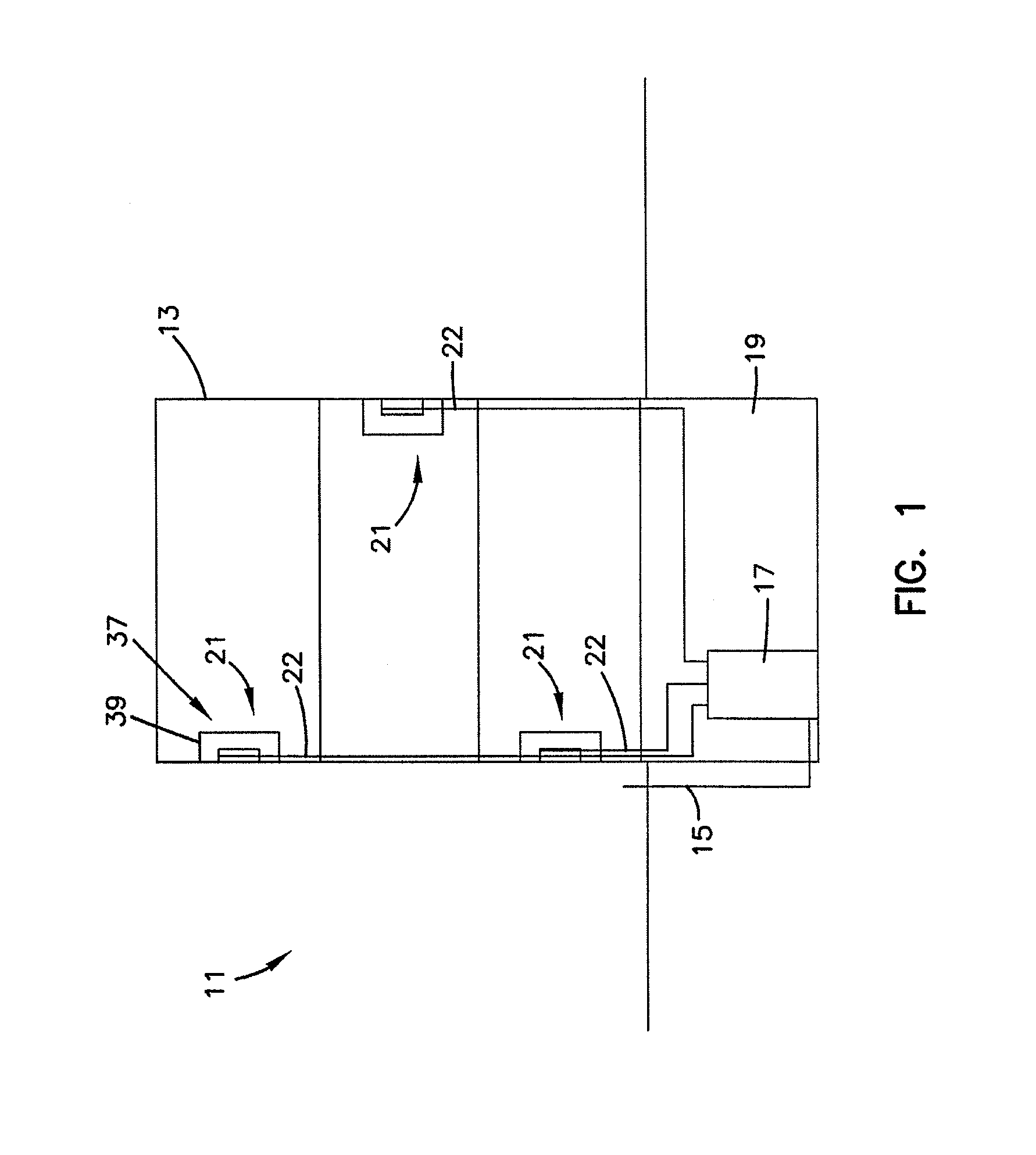
FIG. 1 is a schematic representation of a fiber optic network that includes a fiber optic enclosure having features that are examples of inventive aspects in accordance with the principles of the present disclosure.
FIG. 2 is an isometric view of the fiber optic enclosure of FIG. 1.
FIG. 3 is an isometric view of the fiber optic enclosure of FIG. 2 with a cover in an open position.
FIG. 4 is a front view of the fiber optic enclosure of FIG. 2 with the cover in the open position.
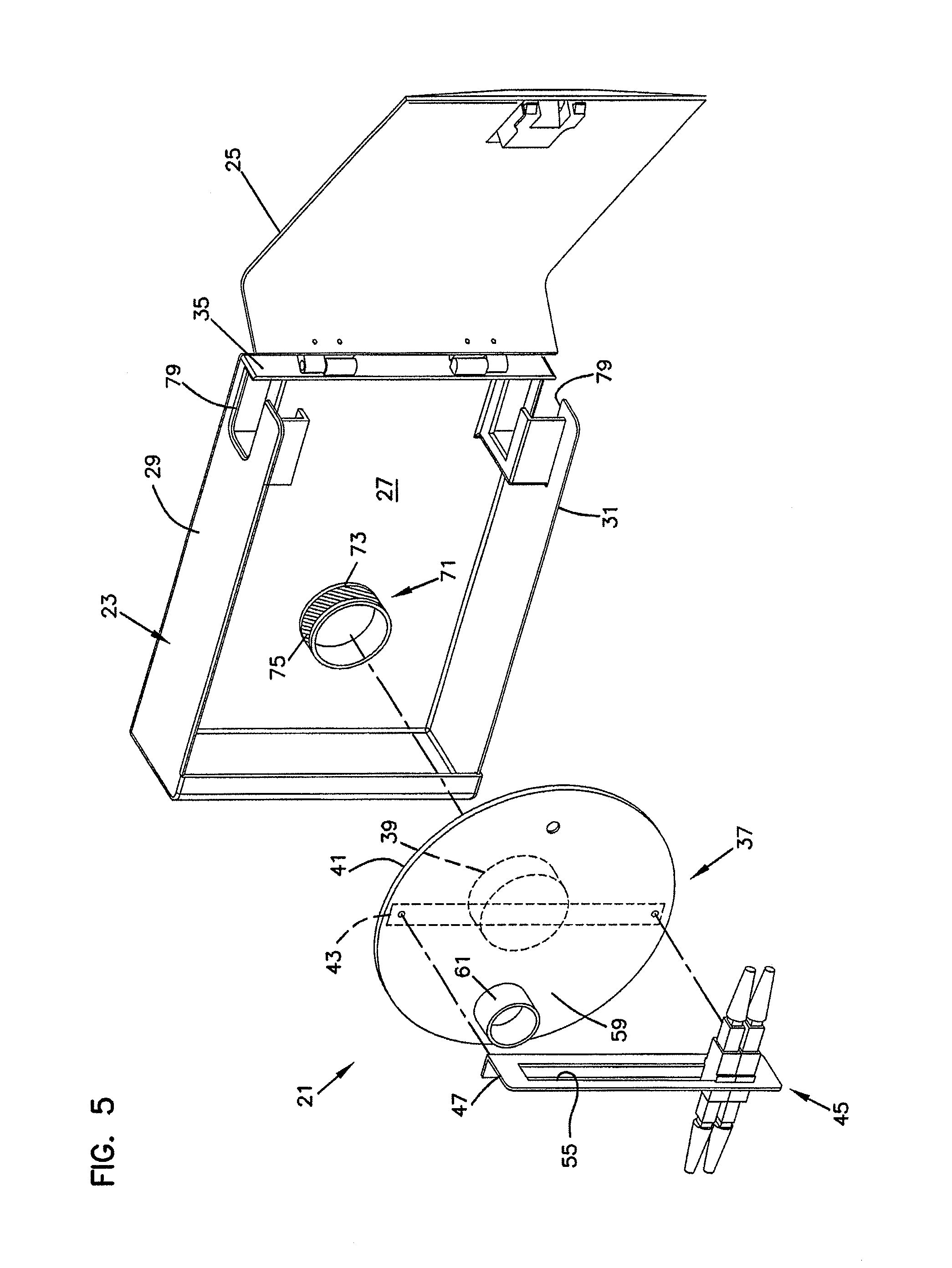
FIG. 5 is an exploded isometric view of the fiber optic enclosure of FIG. 2.
FIG. 6 is a perspective view of a fiber optic adapter suitable for use within the fiber optic enclosure of FIG. 2.
FIG. 7 is a cross-sectional view of the fiber optic adapter taken on line 7-7 of FIG. 6.
FIG. 8 is an isometric view of another embodiment of a fiber optic enclosure.
FIG. 9 is a front view of the fiber optic enclosure of FIG. 8.
FIG. 10 is a top view of the fiber optic enclosure of FIG. 8.
FIG. 11 is a side view of the fiber optic enclosure of FIG. 8.
FIG. 12 is an isometric view of the fiber optic enclosure of FIG. 8, showing cables entering and exiting the enclosure.
FIG. 13 is an isometric view of the fiber optic enclosure of FIG. 12 without the cover.
FIG. 14 is a front view of the fiber optic enclosure of FIG. 13.
FIG. 15 is an exploded isometric view of the fiber optic enclosure of FIG. 13.
FIG. 16 is an isometric view of the cable spool of the fiber optic enclosure of FIG. 13.
FIG. 17 is a further isometric view of the fiber optic enclosure of FIG. 12, with the cover in the pivoted open position.
FIG. 18 is an exploded view of a shipping container in which is disposed the fiber optic enclosure of FIG. 8.
DETAILED DESCRIPTION
Reference will now be made in detail to the exemplary aspects of the present disclosure that are illustrated in the accompanying drawings. Wherever possible, the same reference numbers will be used throughout the drawings to refer to the same or like structure.
Referring now to FIG. 1, a schematic representation of a fiber optic network, generally designated 11, in a facility 13 (e.g. individual residence, apartment, condominium, business, etc.) is shown. The fiber optic network 11 includes a feeder cable 15 from a central office (not shown). The feeder cable 15 enters a feeder cable input location 17 (e.g., a fiber distribution hub, a network interface device, etc.) having one or more optical splitters (e.g., 1-to-8 splitters, 1-to-16 splitters, or 1-to-32 splitters) that generate a number of individual fibers. In the subject embodiment, and by way of example only, the fiber distribution hub 17 is located on a lower level 19 of the facility 13. Each unit in the facility 13 includes a fiber optic enclosure, generally designated 21, with a subscriber cable 22 extending from each of the fiber optic enclosures 21 to the fiber distribution hub 17. The subscriber cable 22 extending between the fiber distribution hub 17 and the fiber optic enclosure 21 typically includes multiple optical fibers.
Referring now to FIGS. 2-5, the fiber optic enclosure 21 will now be described. The fiber optic enclosure 21 includes a housing, generally designated 23, having a cover 25.
The housing 23 includes a base 27, a first sidewall 29, and an oppositely disposed second sidewall 31. The first and second sidewalls 29, 31 extend outwardly from the base 27 such that the base 27 and the first and second sidewalls 29, 31 cooperatively define an interior region 33. In the subject embodiment, the cover 25 is hingedly engaged with a sidewall 35 that is connected to the base 27 and the first and second sidewalls 29, 31. It will be understood, however, that the scope of the present disclosure is not limited to the cover 25 being hingedly engaged the sidewall 35.
A cable spool, generally designated 37, is disposed in the interior region 33 of the fiber optic enclosure 21. The cable spool 37 includes a spooling portion 39, around which subscriber cable 22 is coiled (shown schematically in FIG. 1). The cable spool 37 further includes an axial end 41.
In the subject embodiment, the axial end 41 of the cable spool 37 defines a termination area 43 (shown as a dashed line in FIG. 5). Disposed in the termination area 43 is a termination module, generally designated 45. The termination module 45 of the fiber optic enclosure 21 serves as the dividing line between the incoming fibers and the outgoing fibers.
In the subject embodiment, the termination module 45 includes an adapter plate 47. The adapter plate 47 is an L-shaped bracket having a first side 49 (shown in FIG. 4) and a second side 51. The first side 49 defines a plurality of mounting holes 53 while the second side 51 defines an adapter slot 55. It will be understood, however, that the scope of the present disclosure is not limited to the adapter plate 47 being an L-shaped bracket. The first side 49 of the adapter plate 47 is rigidly mounted (i.e., non-rotatable) to the axial end 41 of the cable spool 37 through a plurality of fasteners 57 (e.g., bolts, screws, rivets, etc.) which are inserted through the mounting holes 53 in the first side 49 and in connected engagement with the axial end 41 of the cable spool 37.
The adapter slot 55 in the second side 51 of the adapter plate 47 is adapted to receive a plurality of adapters, generally designated 401. In the subject embodiment, the adapters 401 are SC-type adapters 401, although it will be understood that the scope of the present disclosure is not limited to the use of SC-type adapters 401. Similar SC-type adapters 401 have been described in detail in commonly owned U.S. Pat. No. 5,317,663, the disclosure of which is incorporated herein by reference.
Referring now to FIGS. 6 and 7, the SC-type adapter 401 includes a main body 403 with a pair of tabs 405, 407 located on the exterior of the main body 403. The tabs 405, 407 serve to support the adapter 401 in the adapter slot 55. The adapter 401 further includes a pair of retaining clips 409, 411, with one retaining clip 409, 411 associated with each tab 405, 407. A front side 413 of the adapter 401 is inserted into the adapter slot 55. As the adapter 401 is inserted through the adapter slot 55, the retaining clips 409, 411 compress against the main body 403. The adapter 401 is inserted into the adapter slot 55 until the tabs 405, 407 abut the adapter plate 47.
With the tabs 405, 407 abutting the adapter plate 47, the retaining clips 409, 411 decompress on the opposite side of the adapter plate 47, thereby retaining the adapter plate 47 between the retaining clips 409, 411 and the tabs 405, 407.
In an alternate embodiment, the termination module includes a plurality of sliding adapter modules. Similar sliding adapter modules have been described in detail in commonly owned U.S. Pat. Nos. 5,497,444; 5,717,810, 6,591,051 and U.S. Pat. Pub. No. 2007/0025675, the disclosures of which are incorporated herein by reference.
Referring now to FIGS. 3-5, the axial end 41 of the cable spool 37 further defines a slack storage area 59. The slack storage area 59 includes a cable management spool 61 disposed on the axial end 41 of the cable spool 37. The cable management spool 61 is sized such that an outer radius of the cable management spool 61 is larger than the minimum bend radius of the optical fibers so as to avoid attenuation damage to the optical fibers during storage.
The cable management spool 61 and the axial end 41 of the cable spool 37 cooperatively define a cable passage 63 that extends axially through the cable management spool 61 and through the axial end 41 of the cable spool 37. The cable passage 63 allows connectorized ends of incoming optical fibers to pass from the spooling portion 39 of the cable spool 37 to the slack storage area 59. The connectorized ends of the incoming optical fibers are then routed from the slack storage area 59 to the front sides 413 of the adapters 401 in the termination area 43.
Referring now to FIG. 5, the fiber optic enclosure 21 further includes a bearing mount, generally designated 71. In the subject embodiment, the bearing mount 71 is disposed on the base 27 of the housing 23. An outer surface 73 of the bearing mount 71 is adapted for a bearing 75 (shown as cross-hatching). In the subject embodiment, the bearing 75 is a needle bearing. However, it will be understood that the scope of the present disclosure is not limited to the bearing 75 being a needle bearing as the bearing 75 could also include a bushing, low-friction coating, etc.
In one embodiment, the bearing 75 is engaged with an inner diameter of a central hole of the cable spool 37. In another embodiment, a rotary plain bearing is formed between the outer surface 73 of the bearing mount 71 and the inner diameter of the central hole of the cable spool 37. In this embodiment, the outer diameter of the bearing mount 71 is sized to fit within an inner diameter of a central hole of the spooling portion 39. The engagement of the bearing mount 71 and the spooling portion 39 of the cable spool 37 allows the cable spool 37 to rotate about the central axis 77 of the bearing mount 71.
Referring now to FIGS. 1 and 5, the subscriber cable 22, which includes multiple optical fibers, is coiled around the spooling portion 39 of the cable spool 37. In order to protect the subscriber cable 22 from attenuation resulting from the coiling of the subscriber cable 22 around the spooling portion 39, the cable spool 37 has an outer circumferential surface having a radius that is greater than the minimum bend radius of the subscriber cable 22. The subscriber cable 22 includes a first end having connectorized ends, which are inserted through the cable passage 63 and connectedly engaged with the first ends 413 of the adapters 401. A second end of the subscriber cable 22 is configured for connectivity with the fiber distribution hub 17. However, as shown in FIG. 1, the length of subscriber cable 22 needed between each of the fiber optic enclosures 21 in the facility 13 and the fiber distribution hub 17 will vary depending upon the location of each fiber optic enclosure 21 with respect to the fiber distribution hub 17.
A method of installing and using the fiber optic enclosure 21 to account for the varying lengths of subscriber cable 22 needed between the fiber optic enclosure 21 and the fiber distribution hub 17 will now be described. The fiber optic enclosure 21 provides dual functionality by serving as a storage location for the subscriber cable 22 and by selectively paying out a desired length of the subscriber cable 22.
A first length of subscriber cable 22 is stored in the fiber optic enclosure 21 by coiling the length of subscriber cable 22 around the cable spool 37. The first length of subscriber cable 22 includes an installation length, which is sufficiently long to extend from the mounting location of the enclosure 28 to the fiber distribution hub 17, and an excess length, which is the length of subscriber cable 22 remaining on the cable spool 37 after the installation length has been paid out. In one embodiment, the first length is greater than or equal to about 100 feet. In another embodiment, the first length of subscriber cable 22 is greater than or equal to about 200 feet. In another embodiment, the first length of subscriber cable 22 is greater than or equal to about 300 feet. In another embodiment, the first length of subscriber cable 22 is greater than or equal to about 400 feet. In another embodiment, the first length of subscriber cable 22 is greater than or equal to about 500 feet. In another embodiment, the first length of subscriber cable 22 is in the range of about 100 to about 2,000 feet. In another embodiment, the first length of subscriber cable 22 is in the range of about 100 to about 1,500 feet. In another embodiment, the first length of subscriber cable 22 is in the range of about 500 to about 1,500 feet. In a preferred embodiment, the first length of subscriber cable 22, which is coiled around the cable spool 89, is in the range of 100 to 500 feet.
In one embodiment, a second length, or the excess length, of subscriber cable 22 is stored around the cable spool 37 after the first length of subscriber cable 22 has been paid out. If the first length of subscriber cable 22 is greater than the installation length of subscriber cable 22, the second length, or excess length, is stored around the cable spool 37.
The second function of the fiber optic enclosure 21 involves the selective payout of the subscriber cable 22. With the cable spool 37 mounted to the bearing mount 71, the first end of the subscriber cable 22 in connected engagement with the front sides 413 of the adapters 401 and the outgoing optical fibers disengaged from the back sides of the adapters 401, the subscriber cable 22 can be paid out through fiber ports 79 disposed in the first and second sidewalls 29, 31. The subscriber cable 22 is paid out of the fiber optic enclosure 21 by selectively rotating the cable spool 37 with respect to the housing 23 about the central axis 77 of the bearing mount 71. As the termination module 45 is disposed on the axial end 41 of the cable spool 37, the selective rotation of the cable spool 37 with respect to the housing 23 results in the selective rotation of the termination module 45. Since the termination module 45 rotates unitarily with or in unison with the cable spool 37, the second end of the subscriber cable 22 can be paid out without the first end of the subscriber cable 22 being pulled out of the termination module 45.
Once the desired length of subscriber cable 22 has been paid out, the rotation of the cable spool 37 is ceased. At this point, the position of the cable spool 37 can be fixed such that it does not rotate relative to the housing 23. In one embodiment, a pin is inserted through an opening in the axial end 41 of the cable spool 37 and through a corresponding opening in the base 27 of the housing 23 to fix the position of the cable spool 37 with respect to the housing 23. It will be understood, however, that the scope of th
References
D00000
D00001
D00002
D00003
D00004
D00005
D00006
D00007
D00008
D00009
D00010
D00011
D00012

D00013

D00014

XML
uspto.report is an independent third-party trademark research tool that is not affiliated, endorsed, or sponsored by the United States Patent and Trademark Office (USPTO) or any other governmental organization. The information provided by uspto.report is based on publicly available data at the time of writing and is intended for informational purposes only.
While we strive to provide accurate and up-to-date information, we do not guarantee the accuracy, completeness, reliability, or suitability of the information displayed on this site. The use of this site is at your own risk. Any reliance you place on such information is therefore strictly at your own risk.
All official trademark data, including owner information, should be verified by visiting the official USPTO website at www.uspto.gov. This site is not intended to replace professional legal advice and should not be used as a substitute for consulting with a legal professional who is knowledgeable about trademark law.