Modular rail and step system
Stanesic , et al.
U.S. patent number 10,604,077 [Application Number 16/536,021] was granted by the patent office on 2020-03-31 for modular rail and step system. This patent grant is currently assigned to LUND, INC.. The grantee listed for this patent is Lund, Inc.. Invention is credited to William Franklin Bibb, VI, Brian T. Johnson, John Matthew Stanesic, John A. Wargo.


View All Diagrams
| United States Patent | 10,604,077 |
| Stanesic , et al. | March 31, 2020 |
Modular rail and step system
Abstract
A modular side rail and removable step system for a vehicle is disclosed. In one aspect, the kit includes first, second, and third removable steps that may be mounted to the side rail. In one aspect, the side rail main body has a channel-shape defining a longitudinal opening between an adjacent first side and an adjacent second side. A plurality of step attachment arrangements may be provided on the first side of the side rail main body to allow the first, second, and third steps to be mounted to the side rail main body in various configurations. For example the plurality of step attachment arrangements may be arranged and configured to provide attachment locations for mounting the first and third removable steps in a first step assembly configuration and for mounting the second removable step in a second step assembly configuration.
| Inventors: | Stanesic; John Matthew (Dacula, GA), Bibb, VI; William Franklin (Buford, GA), Johnson; Brian T. (Lawrenceville, GA), Wargo; John A. (Atlanta, GA) | ||||||||||
|---|---|---|---|---|---|---|---|---|---|---|---|
| Applicant: |
|
||||||||||
| Assignee: | LUND, INC. (Buford,
GA) |
||||||||||
| Family ID: | 52739363 | ||||||||||
| Appl. No.: | 16/536,021 | ||||||||||
| Filed: | August 8, 2019 |
Prior Publication Data
| Document Identifier | Publication Date | |
|---|---|---|
| US 20200031287 A1 | Jan 30, 2020 | |
Related U.S. Patent Documents
| Application Number | Filing Date | Patent Number | Issue Date | ||
|---|---|---|---|---|---|
| 15726171 | Oct 5, 2017 | 10391944 | |||
| 14875003 | Nov 7, 2017 | 9809172 | |||
| 14039659 | Oct 13, 2015 | 9156406 | |||
| Current U.S. Class: | 1/1 |
| Current CPC Class: | H04N 19/91 (20141101); G06T 1/20 (20130101); H04N 19/436 (20141101); H04N 19/433 (20141101); B60R 3/007 (20130101); B60R 3/002 (20130101); G06T 1/60 (20130101); H04N 19/40 (20141101); Y10T 29/49904 (20150115) |
| Current International Class: | B60R 3/00 (20060101); G06T 1/20 (20060101); G06T 1/60 (20060101); H04N 19/436 (20140101); H04N 19/40 (20140101); H04N 19/433 (20140101); H04N 19/91 (20140101) |
References Cited [Referenced By]
U.S. Patent Documents
| 7591 | August 1850 | Burdett |
| 752031 | February 1904 | Chadwick |
| 955658 | April 1910 | Mitchell et al. |
| 1250604 | December 1917 | Lorenc |
| 1449031 | March 1923 | Blake |
| 1471972 | October 1923 | Miller |
| 2041640 | May 1936 | Goss |
| 2122040 | June 1938 | Machovec |
| 2125085 | July 1938 | Pool |
| 2436961 | March 1948 | Gabriel |
| 2487921 | November 1949 | Culver |
| 2492068 | December 1949 | Schofield et al. |
| 2566401 | September 1951 | Bustin |
| 2575615 | November 1951 | Crump |
| 2583894 | January 1952 | Shuck |
| 2669613 | February 1954 | Despard |
| 2678832 | May 1954 | Wright |
| 2764422 | September 1956 | McDonald |
| 2925876 | February 1960 | Wagner |
| 3039562 | June 1962 | Wagner |
| 3095216 | June 1963 | Browne |
| 3172499 | March 1965 | Stairs |
| 3329443 | July 1967 | Lowder et al. |
| 3392990 | July 1968 | Wolf |
| 3488066 | January 1970 | Hansen |
| 3494634 | February 1970 | De Paula |
| 3522396 | July 1970 | Norden |
| 3528574 | September 1970 | Denner et al. |
| 3572754 | March 1971 | Fowler |
| 3608957 | September 1971 | Maneck |
| 3671058 | June 1972 | Kent |
| 3762742 | October 1973 | Bucklen |
| 3807757 | April 1974 | Carpenter et al. |
| 3833240 | September 1974 | Weiler |
| 3865399 | February 1975 | Way |
| 3887217 | June 1975 | Thomas |
| 3889997 | June 1975 | Schoneck |
| 3891261 | June 1975 | Finneman |
| 3957284 | May 1976 | Wright |
| 3961809 | June 1976 | Clugston |
| 3980319 | September 1976 | Kirkpatrick |
| 3981515 | September 1976 | Rosborough |
| 4020920 | May 1977 | Abbott |
| 4068542 | January 1978 | Brand et al. |
| 4073502 | February 1978 | Frank et al. |
| 4089538 | May 1978 | Eastridge |
| 4106790 | August 1978 | Weiler |
| 4110673 | August 1978 | Nagy et al. |
| 4116457 | September 1978 | Nerem et al. |
| 4164292 | August 1979 | Karkau |
| 4174021 | November 1979 | Barlock |
| 4180143 | December 1979 | Clugston |
| 4185849 | January 1980 | Jaeger |
| 4188889 | February 1980 | Favrel |
| 4231583 | November 1980 | Learn |
| 4312515 | January 1982 | Allori |
| 4424751 | January 1984 | Blochlinger |
| 4440364 | April 1984 | Cone et al. |
| 4462486 | July 1984 | Dignan |
| 4536004 | August 1985 | Brynielsson et al. |
| 4542805 | September 1985 | Hamlin et al. |
| 4570962 | February 1986 | Chavira |
| 4623160 | November 1986 | Trudell |
| D287001 | December 1986 | Jarvie et al. |
| 4679810 | July 1987 | Kimball |
| D292904 | November 1987 | Bielby |
| 4720116 | January 1988 | Williams et al. |
| 4733752 | March 1988 | Sklar |
| 4909700 | March 1990 | Fontecchio et al. |
| 4982974 | January 1991 | Guidry |
| 5005667 | April 1991 | Anderson |
| 5005850 | April 1991 | Baughman |
| 5039119 | August 1991 | Baughman |
| 5085450 | February 1992 | DeHart, Sr. |
| 5137294 | August 1992 | Martin |
| 5154125 | October 1992 | Renner et al. |
| 5195609 | March 1993 | Ham et al. |
| 5199731 | April 1993 | Martin |
| 5228707 | July 1993 | Yoder |
| 5228761 | July 1993 | Huebschen et al. |
| 5238300 | August 1993 | Slivon et al. |
| D340905 | November 1993 | Orth et al. |
| 5257847 | November 1993 | Yonehara |
| 5284349 | February 1994 | Bruns et al. |
| 5286049 | February 1994 | Khan |
| 5342073 | August 1994 | Poole |
| 5358268 | October 1994 | Hawkins |
| 5375864 | December 1994 | McDaniel |
| 5423463 | June 1995 | Weeks |
| 5439342 | August 1995 | Hall et al. |
| 5462302 | October 1995 | Leitner |
| 5478124 | December 1995 | Warrington |
| 5498012 | March 1996 | McDaniel et al. |
| 5501475 | March 1996 | Bundy |
| 5505476 | April 1996 | Maccabee |
| 5513866 | May 1996 | Sisson |
| 5538100 | July 1996 | Hedley |
| 5538265 | July 1996 | Chen et al. |
| 5538269 | July 1996 | McDaniel et al. |
| 5547040 | August 1996 | Hanser et al. |
| 5584493 | December 1996 | Demski et al. |
| 5601300 | February 1997 | Fink et al. |
| 5697623 | December 1997 | Bermes et al. |
| 5697626 | December 1997 | McDaniel |
| 5727840 | March 1998 | Ochiai et al. |
| 5779208 | July 1998 | McGraw |
| 5842709 | December 1998 | Maccabee |
| 5897125 | April 1999 | Bundy |
| 5941342 | August 1999 | Lee |
| 5957237 | September 1999 | Tigner |
| 6042052 | March 2000 | Smith et al. |
| 6055780 | May 2000 | Yamazaki |
| 6082751 | July 2000 | Hanes et al. |
| 6112152 | August 2000 | Tuttle |
| 6149172 | November 2000 | Pascoe et al. |
| 6168176 | January 2001 | Mueller |
| 6179312 | January 2001 | Paschke et al. |
| 6203040 | March 2001 | Hutchins |
| 6213486 | April 2001 | Kunz et al. |
| 6264222 | July 2001 | Johnston et al. |
| 6270099 | August 2001 | Farkash |
| 6325397 | December 2001 | Pascoe |
| 6352295 | March 2002 | Leitner |
| 6375207 | April 2002 | Dean et al. |
| 6412799 | July 2002 | Schrempf |
| 6422342 | July 2002 | Armstrong et al. |
| 6425572 | July 2002 | Lehr |
| 6430164 | August 2002 | Jones et al. |
| 6435534 | August 2002 | Stone |
| 6439342 | August 2002 | Boykin |
| 6460915 | October 2002 | Bedi et al. |
| 6511086 | January 2003 | Schlicht |
| 6513821 | February 2003 | Heil |
| 6533303 | March 2003 | Watson |
| 6588783 | July 2003 | Fichter |
| 6641158 | November 2003 | Leitner |
| 6659484 | December 2003 | Knodle et al. |
| 6663125 | December 2003 | Cheng |
| 6746033 | June 2004 | McDaniel |
| 6769704 | August 2004 | Cipolla |
| 6810995 | November 2004 | Warford |
| 6812466 | November 2004 | O'Connor et al. |
| 6830257 | December 2004 | Leitner |
| 6834875 | December 2004 | Leitner |
| 6840526 | January 2005 | Anderson et al. |
| 6874801 | April 2005 | Fichter |
| 6880843 | April 2005 | Greer, Jr. |
| 6912912 | July 2005 | Reichinger et al. |
| 6918624 | July 2005 | Miller et al. |
| 6926295 | August 2005 | Berkebile et al. |
| 6938909 | September 2005 | Leitner |
| 6942233 | September 2005 | Leitner et al. |
| 6942272 | September 2005 | Livingston |
| 6948903 | September 2005 | Ablabutyan et al. |
| 6951357 | October 2005 | Armstrong et al. |
| 6955370 | October 2005 | Fabiano et al. |
| 6959937 | November 2005 | Schneider et al. |
| 6966597 | November 2005 | Tegtmeier |
| 6971652 | December 2005 | Bobbert et al. |
| 6997469 | February 2006 | Lanoue et al. |
| 7000932 | February 2006 | Heil et al. |
| 7007961 | March 2006 | Leitner |
| 7017927 | March 2006 | Henderson et al. |
| 7055839 | June 2006 | Leitner |
| 7070194 | July 2006 | Garland et al. |
| 7090276 | August 2006 | Bruford et al. |
| 7111858 | September 2006 | Manser et al. |
| 7111859 | September 2006 | Kim et al. |
| 7118120 | October 2006 | Lee et al. |
| 7118150 | October 2006 | Bruford et al. |
| 7163221 | January 2007 | Leitner |
| 7185904 | March 2007 | Jones |
| 7219911 | May 2007 | Sukonthapanich et al. |
| 7258386 | August 2007 | Leitner |
| 7287770 | October 2007 | Drabant et al. |
| 7287771 | October 2007 | Lee et al. |
| 7311320 | December 2007 | Kuntze et al. |
| 7318596 | January 2008 | Scheuring, III et al. |
| 7360779 | April 2008 | Crandall |
| 7367574 | May 2008 | Leitner |
| 7377531 | May 2008 | Fabiano et al. |
| 7380807 | June 2008 | Leitner |
| 7398985 | July 2008 | Leitner et al. |
| 7413204 | August 2008 | Leitner |
| 7413205 | August 2008 | Watson |
| 7413233 | August 2008 | Jung |
| 7416202 | August 2008 | Fichter |
| 7434825 | October 2008 | Williams |
| 7438305 | October 2008 | Schulz |
| 7441790 | October 2008 | Lechkun |
| 7445221 | November 2008 | Kobayashi |
| 7469916 | December 2008 | Watson |
| 7487986 | February 2009 | Leither et al. |
| 7513520 | April 2009 | Okuyama |
| 7513565 | April 2009 | Watson |
| 7516703 | April 2009 | Tazreiter |
| 7530619 | May 2009 | Bruford et al. |
| 7566064 | July 2009 | Leitner et al. |
| 7584975 | September 2009 | Leitner |
| 7585033 | September 2009 | Holt |
| 7594672 | September 2009 | Piotrowski |
| 7621546 | November 2009 | Ross et al. |
| 7635247 | December 2009 | Collins |
| 7637519 | December 2009 | Leitner et al. |
| 7673892 | March 2010 | Kuntze et al. |
| 7703784 | April 2010 | Plavetich |
| 7712755 | May 2010 | Yang et al. |
| 7717444 | May 2010 | Fichter |
| D618148 | June 2010 | Hoppert |
| 7731212 | June 2010 | Storer |
| 7740260 | June 2010 | VanBelle et al. |
| 7740261 | June 2010 | Leitner et al. |
| 7766357 | August 2010 | Arvanites |
| 7775536 | August 2010 | Shumway |
| 7793596 | September 2010 | Hirtenlehner |
| 7823896 | November 2010 | VanBelle |
| 7874565 | January 2011 | Duncan |
| D634687 | March 2011 | Vukel |
| 7900944 | March 2011 | Watson |
| 7909344 | March 2011 | Bundy |
| 7934737 | May 2011 | Okada |
| 7976042 | July 2011 | Watson et al. |
| 8038164 | October 2011 | Stahl et al. |
| 8042821 | October 2011 | Yang |
| D649100 | November 2011 | Cheng |
| 8052162 | November 2011 | Yang et al. |
| 8056913 | November 2011 | Kuntze et al. |
| 8070173 | December 2011 | Watson |
| 8136826 | March 2012 | Watson |
| 8157277 | April 2012 | Leitner et al. |
| 8177247 | May 2012 | Carr |
| 8205901 | June 2012 | Yang et al. |
| D665713 | August 2012 | Pochurek et al. |
| 8262113 | September 2012 | Chafey et al. |
| 8297635 | October 2012 | Agoncillo et al. |
| D671874 | December 2012 | Kekich et al. |
| 8342550 | January 2013 | Stickles et al. |
| 8342551 | January 2013 | Watson et al. |
| 8360455 | January 2013 | Leitner et al. |
| D676368 | February 2013 | Cover |
| 8366129 | February 2013 | Salmon |
| 8382132 | February 2013 | Kowalski |
| 8408571 | April 2013 | Leitner et al. |
| 8419034 | April 2013 | Leitner et al. |
| 8448967 | May 2013 | Storer |
| 8448968 | May 2013 | Grote et al. |
| 8463953 | June 2013 | Davis et al. |
| 8469380 | June 2013 | Yang et al. |
| 8602431 | December 2013 | May |
| 8641068 | February 2014 | Bundy |
| 8662512 | March 2014 | May |
| 8668217 | March 2014 | Ziaylek |
| 8696005 | April 2014 | Kim |
| 8827293 | September 2014 | Bundy |
| 8827294 | September 2014 | Leitner et al. |
| 8833782 | September 2014 | Huotari |
| 8844957 | September 2014 | Leitner et al. |
| D720674 | January 2015 | Stanesic et al. |
| 8936266 | January 2015 | Leitner et al. |
| 8944451 | February 2015 | Leitner et al. |
| 8985606 | March 2015 | Fichter |
| 9156406 | October 2015 | Stanesic et al. |
| 9272667 | March 2016 | Smith |
| 9302626 | April 2016 | Leitner et al. |
| 9308870 | April 2016 | Yang |
| 9346404 | May 2016 | Bundy |
| 9346405 | May 2016 | Leitner et al. |
| 9434317 | September 2016 | Nania |
| 9452713 | September 2016 | Stickles |
| 9511717 | December 2016 | Smith |
| 9522634 | December 2016 | Smith |
| 9527449 | December 2016 | Smith |
| 9550458 | January 2017 | Smith et al. |
| 9561751 | February 2017 | Leitner et al. |
| 9656609 | May 2017 | Du et al. |
| 9669766 | June 2017 | Du et al. |
| 9669767 | June 2017 | Du et al. |
| 9688205 | June 2017 | Du et al. |
| 9701249 | July 2017 | Leitner et al. |
| 9809172 | November 2017 | Stanesic |
| 9834147 | December 2017 | Smith |
| 9902328 | February 2018 | Mazur |
| 9944231 | April 2018 | Leitner et al. |
| 10053017 | August 2018 | Leitner et al. |
| 10065486 | September 2018 | Smith et al. |
| 10077016 | September 2018 | Smith et al. |
| 10081302 | September 2018 | Frederick et al. |
| 10106069 | October 2018 | Rasekhi |
| 10106086 | October 2018 | Eckstein et al. |
| 10106087 | October 2018 | Stojkovic et al. |
| 10106088 | October 2018 | Smith |
| 10118557 | November 2018 | Pribisic |
| 10124839 | November 2018 | Povinelli et al. |
| 10144345 | December 2018 | Stinson et al. |
| 10150419 | December 2018 | Derbis et al. |
| 10155474 | December 2018 | Salter et al. |
| 10173595 | January 2019 | Ulrich |
| 10183623 | January 2019 | Krishnan et al. |
| 10183624 | January 2019 | Leitner et al. |
| 10189517 | January 2019 | Povinelli et al. |
| 10195997 | February 2019 | Smith |
| 10207598 | February 2019 | Reynolds et al. |
| 10214963 | February 2019 | Simula et al. |
| 10246019 | April 2019 | Carr |
| 10246137 | April 2019 | Ngo |
| 10272841 | April 2019 | Wymore |
| 10272842 | April 2019 | Du et al. |
| 10322677 | June 2019 | Leitner et al. |
| 10336260 | July 2019 | Salter et al. |
| 10336378 | July 2019 | Marchlewski et al. |
| 10343610 | July 2019 | Long et al. |
| 10351182 | July 2019 | Zielinski et al. |
| 10391944 | August 2019 | Stanesic et al. |
| 2002/0109446 | August 2002 | Arnold |
| 2002/0130531 | September 2002 | Leitner |
| 2003/0090081 | May 2003 | Oakley |
| 2003/0094781 | May 2003 | Jaramillo et al. |
| 2003/0200700 | October 2003 | Leitner |
| 2004/0207224 | October 2004 | Miller et al. |
| 2005/0117969 | June 2005 | Byrne |
| 2005/0146157 | July 2005 | Leitner |
| 2005/0263974 | December 2005 | Mulder |
| 2006/0208449 | September 2006 | Kuo et al. |
| 2008/0034552 | February 2008 | Nguyen |
| 2008/0084045 | April 2008 | Filias et al. |
| 2008/0224438 | September 2008 | Okada |
| 2009/0072507 | March 2009 | Storer |
| 2009/0203247 | August 2009 | Fifelski et al. |
| 2009/0308688 | December 2009 | Tayar |
| 2010/0176607 | July 2010 | Hardy et al. |
| 2010/0194070 | August 2010 | Stauffer et al. |
| 2012/0025485 | February 2012 | Yang et al. |
| 2012/0228848 | September 2012 | Fichter |
| 2013/0221632 | August 2013 | Higgs et al. |
| 2015/0321612 | November 2015 | Leitner et al. |
| 2015/0321613 | November 2015 | Leitner et al. |
| 2016/0039346 | February 2016 | Yang |
| 2016/0288718 | October 2016 | Hayes et al. |
| 2017/0008459 | January 2017 | Leitner et al. |
| 2017/0036607 | February 2017 | Du et al. |
| 2017/0190308 | June 2017 | Smith |
| 2017/0246993 | August 2017 | Smith |
| 2017/0267182 | September 2017 | Leitner |
| 2017/0355315 | December 2017 | Leitner |
| 2018/0257572 | September 2018 | Du et al. |
| 2018/0281687 | October 2018 | Derbis et al. |
| 2018/0326911 | November 2018 | Leitner |
| 2019/0009725 | January 2019 | Stojkovic et al. |
| 2019/0047477 | February 2019 | Crandall |
| 2019/0071021 | March 2019 | Pribisic |
| 2019/0071042 | March 2019 | Smith |
| 2019/0084482 | March 2019 | Long et al. |
| 2019/0084628 | March 2019 | Povinelli et al. |
| 2019/0118720 | April 2019 | Otacioglu et al. |
| 2019/0118750 | April 2019 | Bosco |
| 2019/0126832 | May 2019 | Knichel |
| 2019/0126835 | May 2019 | Leitner |
| 2019/0126870 | May 2019 | Rife et al. |
| 2019/0152542 | May 2019 | Povinelli et al. |
| 2019/0176709 | June 2019 | Leitner |
| 2019/0193639 | June 2019 | Smith |
| 2 082 177 | May 1994 | CA | |||
| 2 332 193 | Sep 2001 | CA | |||
| 2174368 | Aug 1994 | CN | |||
| 201280106 | Jul 2009 | CN | |||
| 100545005 | Sep 2009 | CN | |||
| 202758405 | Feb 2013 | CN | |||
| 202847566 | Apr 2013 | CN | |||
| 103149915 | Jun 2013 | CN | |||
| 108791086 | Nov 2018 | CN | |||
| 208232903 | Dec 2018 | CN | |||
| 208325054 | Jan 2019 | CN | |||
| 208344082 | Jan 2019 | CN | |||
| 109318812 | Feb 2019 | CN | |||
| 109318813 | Feb 2019 | CN | |||
| 109383384 | Feb 2019 | CN | |||
| 109383386 | Feb 2019 | CN | |||
| 109383388 | Feb 2019 | CN | |||
| 109383390 | Feb 2019 | CN | |||
| 109383392 | Feb 2019 | CN | |||
| 208452901 | Feb 2019 | CN | |||
| 208559193 | Mar 2019 | CN | |||
| 208731206 | Apr 2019 | CN | |||
| 109795418 | May 2019 | CN | |||
| 208896972 | May 2019 | CN | |||
| 31 51 621 | Jul 1983 | DE | |||
| 39 32 142 | Apr 1990 | DE | |||
| 89 10 933 | Oct 1990 | DE | |||
| 0 066 493 | Dec 1982 | EP | |||
| 1 116 840 | Jul 2001 | EP | |||
| 3 002 157 | Apr 2016 | EP | |||
| 3 176 038 | Jan 2019 | EP | |||
| 3 237 254 | Feb 2019 | EP | |||
| 3 461 713 | Apr 2019 | EP | |||
| 1 350 593 | Dec 1963 | FR | |||
| 2 225 612 | Aug 1974 | FR | |||
| 934387 | Aug 1963 | GB | |||
| 936846 | Sep 1963 | GB | |||
| 2 045 699 | Nov 1980 | GB | |||
| 2 129 378 | May 1984 | GB | |||
| 2 201 511 | Sep 1988 | GB | |||
| 2 288 014 | Oct 1994 | GB | |||
| 201741011829 | Oct 2018 | IN | |||
| 201737025141 | Mar 2019 | IN | |||
| 201741038321 | May 2019 | IN | |||
| 63-255144 | Oct 1988 | JP | |||
| 04-339040 | Nov 1992 | JP | |||
| 04-342629 | Nov 1992 | JP | |||
| 05-310061 | Nov 1993 | JP | |||
| 05-310081 | Nov 1993 | JP | |||
| 8-132967 | May 1996 | JP | |||
| 2018-177089 | Nov 2018 | JP | |||
| 2019-001222 | Jan 2019 | JP | |||
| 6509607 | Apr 2019 | JP | |||
| 2019-069634 | May 2019 | JP | |||
| 2017001699 | Jun 2018 | MX | |||
| 2017001700 | Jun 2018 | MX | |||
| 2017006328 | Jun 2018 | MX | |||
| 2017008032 | Sep 2018 | MX | |||
| 2017010183 | Sep 2018 | MX | |||
| 2018000509 | Nov 2018 | MX | |||
| 403594 | Nov 1972 | SU | |||
| M296187 | Aug 2006 | TW | |||
| M318551 | Sep 2007 | TW | |||
| WO 2001/000441 | Jan 2001 | WO | |||
| WO 2003/039910 | May 2003 | WO | |||
| WO 2003/039920 | May 2003 | WO | |||
| WO 2003/066380 | Aug 2003 | WO | |||
| WO 2003/069294 | Aug 2003 | WO | |||
| WO 2006/050297 | May 2006 | WO | |||
| WO 2009/103163 | Aug 2009 | WO | |||
| WO 2017/020527 | Feb 2017 | WO | |||
| WO 2017/140081 | Aug 2017 | WO | |||
| WO 2017/176226 | Oct 2017 | WO | |||
| WO 2018/148643 | Aug 2018 | WO | |||
| WO 2018/197393 | Nov 2018 | WO | |||
| WO 2019/009131 | Jan 2019 | WO | |||
| WO 2019/034493 | Feb 2019 | WO | |||
Other References
|
N-FAB Catalog, 2013 Collection, Version 2.1, front page, pp. 24, 25, 28, 29, back page (2013). cited by applicant . Rampage Products Catalog, front page, pp. 21 and back page (2013). cited by applicant. |
Primary Examiner: Walters; John D
Assistant Examiner: Triggs; James J
Attorney, Agent or Firm: Knobbe Martens Olson & Bear LLP
Claims
What is claimed is:
1. A modular rail and step system for a vehicle, the system comprising: a side rail main body extending from a forward end to a rearward end and having a top surface, a bottom surface, and an outer surface, the side rail main body configured to extend at least partially along a length of the vehicle; a plurality of mounting brackets configured for mounting the side rail main body to the vehicle in a position beneath one or more doors of the vehicle; and a removable step comprising: a forward mounting portion configured to be removably coupled to the bottom surface of the side rail main body; a rearward mounting portion configured to be removably coupled to the bottom surface of the side rail main body; a support portion extending from the forward mounting portion to the rearward mounting portion, the support portion comprising a forward portion that extends downward and rearward from the forward mounting portion and a rearward portion that extends downward and forward from the rearward mounting portion; and a step portion attached to the support portion, the step portion positioned to be spaced apart from the side rail main body and extend parallel to the length of the vehicle when the forward mounting portion and the rearward mounting portion are coupled to the bottom surface of the side rail main body.
2. The modular rail and step system of claim 1, wherein the support portion of the removable step comprises a round bar extending from the forward mounting portion to the rearward mounting portion.
3. The modular rail and step system of claim 1, wherein the forward mounting portion and the rearward mounting portion each comprise a channel shape.
4. The modular rail and step system of claim 1, wherein the forward portion of the support portion further extends outward from the forward mounting portion, and the rearward portion of the support portion further extends outward from the rearward mounting portion.
5. The modular rail and step system of claim 1, wherein the step portion comprises a stepping surface having a plurality of openings passing therethrough.
6. The modular rail and step system of claim 1, wherein the step portion is attached to a top surface of the support portion.
7. The modular rail and step system of claim 1, wherein the forward mounting portion and the rearward mounting portion each comprise a mounting slot for coupling the removable step to the bottom surface of the side rail main body, the mounting slot extending along a first direction.
8. The modular rail and step system of claim 7, wherein the bottom surface of the side rail main body comprises a plurality of mounting slots configured to couple to the mounting slots of the removable step using fasteners, the plurality of mounting slots of the side rail extending along a second direction.
9. The modular rail and step system of claim 8, wherein the first direction is perpendicular to the second direction.
10. The modular rail and step system of claim 1, wherein the forward mounting portion and the rearward mounting portion each comprise a plurality of mounting slots for coupling the removable step to the bottom surface of the side rail main body.
11. The modular rail and step system of claim 1, wherein a length of the removable step is at least two-thirds a length of the side rail main body.
12. The modular rail and step system of claim 1, further comprising a second removable step configured to be removably coupled to the bottom surface of the side rail main body.
13. A vehicle comprising: a first modular rail and step system attached to a first side of the vehicle, the system comprising: a side rail main body extending from a forward end to a rearward end and having a top surface, a bottom surface, and an outer surface, the side rail main body extending at least partially along a length of the vehicle; a plurality of mounting brackets that mount the side rail main body to the first side of the vehicle in a position beneath one or more doors of the vehicle; and a removable step comprising: a forward mounting portion removably coupled to the bottom surface of the side rail main body; a rearward mounting portion removably coupled to the bottom surface of the side rail main body; a support portion extending from the forward mounting portion to the rearward mounting portion, the support portion comprising a forward portion that extends downward and rearward from the forward mounting portion and a rearward portion that extends downward and forward from the rearward mounting portion; and a step portion attached to the support portion, the step portion spaced apart from the side rail main body and extending parallel to the length of the vehicle.
14. The vehicle of claim 13, further comprising a second modular rail and step system attached to a second side of the vehicle.
15. The vehicle of claim 13, wherein the support portion of the removable step comprises a round bar extending from the forward mounting portion to the rearward mounting portion.
16. The vehicle of claim 13, wherein the forward mounting portion and the rearward mounting portion each comprise a channel shape.
17. The vehicle of claim 13, wherein the forward portion of the support portion further extends outward from the forward mounting portion, and the rearward portion of the support portion further extends outward from the rearward mounting portion.
18. The vehicle of claim 13, wherein the step portion comprises a stepping surface having a plurality of openings passing therethrough.
19. The vehicle of claim 13, wherein the forward mounting portion and the rearward mounting portion each comprise a mounting slot extending along a first direction, the bottom surface of the side rail main body comprises a plurality of mounting slots extending along a second direction, and the first direction is perpendicular to the second direction.
20. The vehicle of claim 13, wherein a length of the removable step is at least two-thirds a length of the side rail main body.
Description
INCORPORATION BY REFERENCE TO ANY PRIORITY APPLICATIONS
Any and all applications for which a foreign or domestic priority claim is identified in the Application Data Sheet as filed with the present application are hereby incorporated by reference under 37 CFR 1.57.
TECHNICAL FIELD
This disclosure relates to a modular side rail and step system for a motor vehicle, a motor vehicle including a modular side rail and step system, and a method for installing a modular side rail to a motor vehicle.
BACKGROUND
Many types of vehicles, including sport utility vehicles (e.g. JEEP.RTM. brand vehicles), pickup trucks, and vans, are raised off the ground farther than normal passenger automobiles. The increased height of the floor of the passenger cab from the ground makes it difficult to enter and exit these vehicles. In addition, if the vehicles are driven over rough terrain, their lower body panels and door panels are susceptible to being scratched, dented, or otherwise damaged by rocks or other ground debris. To address these issues, side rails can be mounted to the vehicle to provide a stepping surface to assist the driver and passengers in entering and exiting these vehicles. In addition, side rails can function to protect the body of the vehicles from being damaged from below. As different types and models of vehicles can have different numbers and locations of doors, it is often necessary to manufacture a number of different side rails and steps that will properly fit each specific type of vehicle. Improvements are desired.
SUMMARY
A modular side rail and removable step system for a vehicle is disclosed. In one aspect, the kit includes a first removable step having a first length and a second removable step having a second length greater than the first length. The kit may also include a third removable step having a third length that is about equal to the first length. In another aspect, the kit includes a side rail main body extending between a first end and a second end wherein the side rail main body has a channel-shape defining a longitudinal opening between an adjacent first side rail member and an adjacent second side rail member. A plurality of spaced mounting brackets can also be provided that are configured for mounting the side rail main body to the vehicle. In one embodiment, each of the plurality of mounting brackets extend through the main body longitudinal opening and are secured to the main body, for example by welding. A plurality of step attachment arrangements may also be provided on the second side rail member of the side rail main body that are offset from the locations of the plurality of mounting brackets. The plurality of step attachment arrangements may also be arranged and configured to provide attachment locations for mounting the first and third removable steps in a first step assembly configuration and for mounting the second removable step in a second step assembly configuration. In one embodiment, at least one of the plurality of step attachment arrangements is configured to provide an attachment location for both the first step and the second steps.
The above described modular side rail and removable step system can be installed on a vehicle having a first door by mounting the side rail to the vehicle below the first door via the mounting brackets. The first and/or second removable steps can be mounted to the side rail main body either before or after the side rail is mounted to the vehicle. If a different step configuration is desired, the first and/or second removable steps can be removed from the side rail main body and replaced with a third removable step. It is noted that the steps can installed and removed in any order to change from one configuration to any other desired configuration.
DESCRIPTION OF THE DRAWINGS
Non-limiting and non-exhaustive embodiments are described with reference to the following figures, which are not necessarily drawn to scale, wherein like reference numerals refer to like parts throughout the various views unless otherwise specified.
FIG. 1 is a perspective view of a motor vehicle provided with a modular side rail and step system in a first step assembly configuration having features that are examples of aspects in accordance with the principles of the present disclosure.
FIG. 2 is a side view of the motor vehicle provided with the modular side rail and step system in the first step assembly configuration of FIG. 1.
FIG. 3 is an enlarged perspective view of a portion of the vehicle provided with the modular side rail and step system in the first step assembly configuration of FIG. 1, as identified at A1 in FIG. 1.
FIG. 4 is an enlarged perspective view of a portion of the vehicle provided with the modular side rail and step system in the first step assembly configuration of FIG. 1, as identified at A2 in FIG. 1.
FIG. 5 is a perspective view of the modular side rail and step system in the first step assembly configuration of FIG. 1.
FIG. 6 is a top view of the modular side rail and step system in the first step assembly configuration of FIG. 1.
FIG. 7 is a side view of the modular side rail and step system in the first step assembly configuration of FIG. 1.
FIG. 8 is a bottom view of the modular side rail and step system in the first step assembly configuration of FIG. 1.
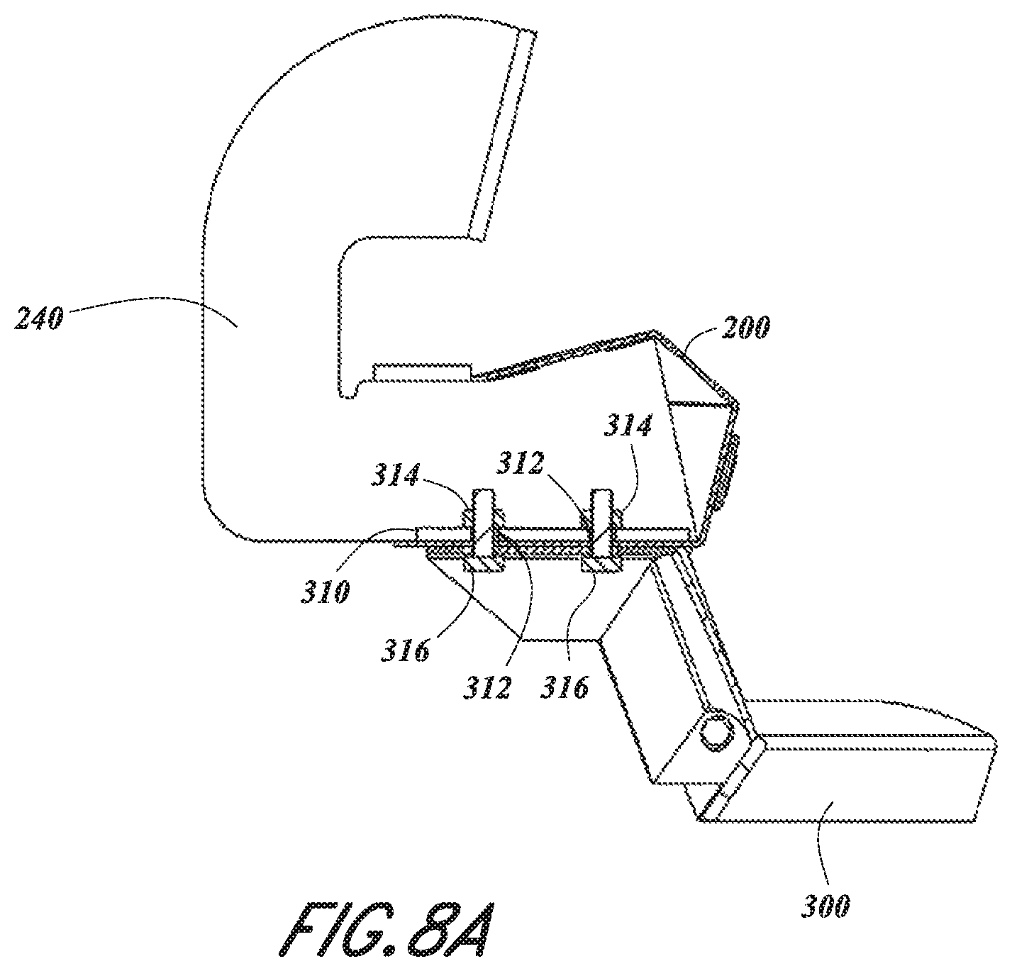
FIG. 8A is a cross-sectional view of the modular side rail and step system in the first step assembly configuration of FIG. 1, taken at a location where a step attaches to the side rail.
FIG. 9 is a perspective view of the modular side rail and brackets of the system shown in FIG. 1.
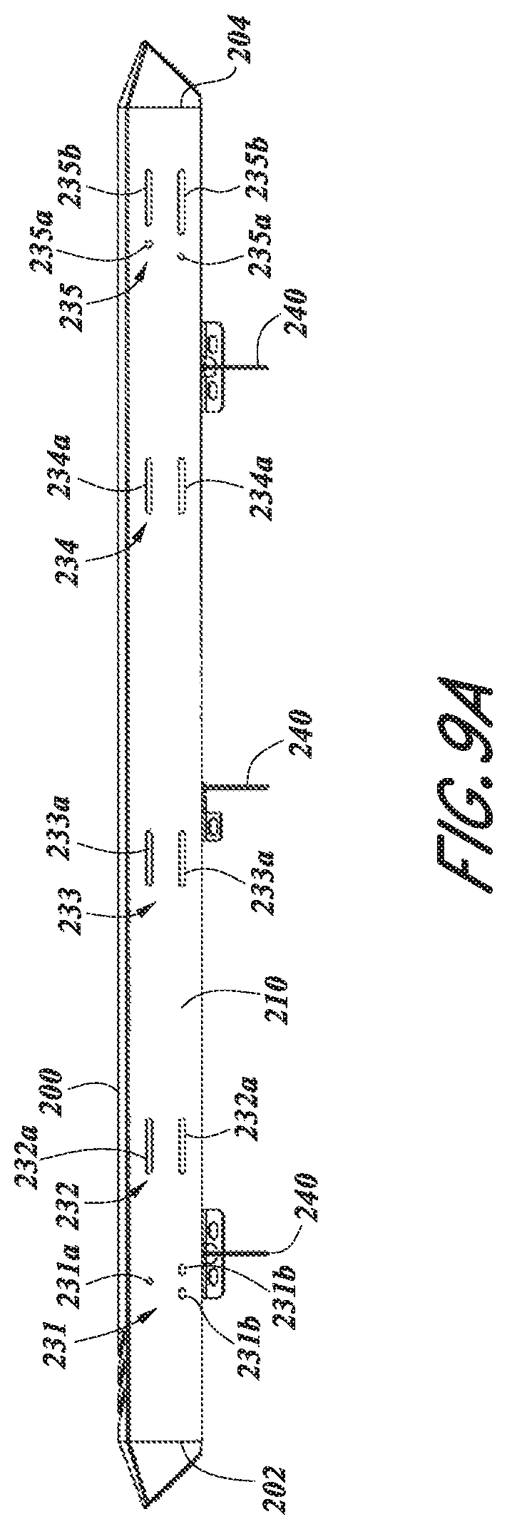
FIG. 9A is a bottom view of the modular side rail and brackets of FIG. 9.
FIG. 10 is a side view of the modular side rail and brackets of FIG. 9.
FIG. 11 is a perspective rear view of a portion of the modular side rail and brackets of FIG. 9.
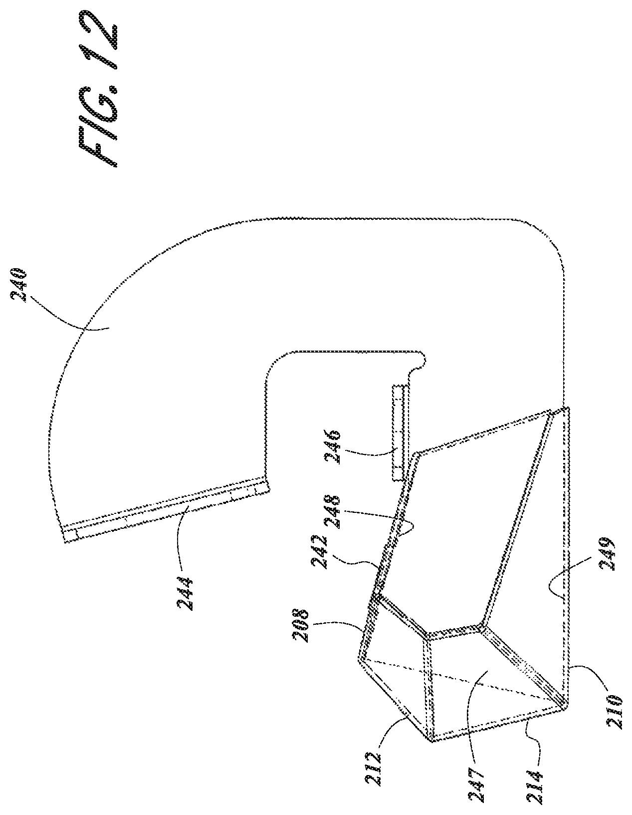
FIG. 12 is an end view of the modular side rail and brackets of FIG. 9.
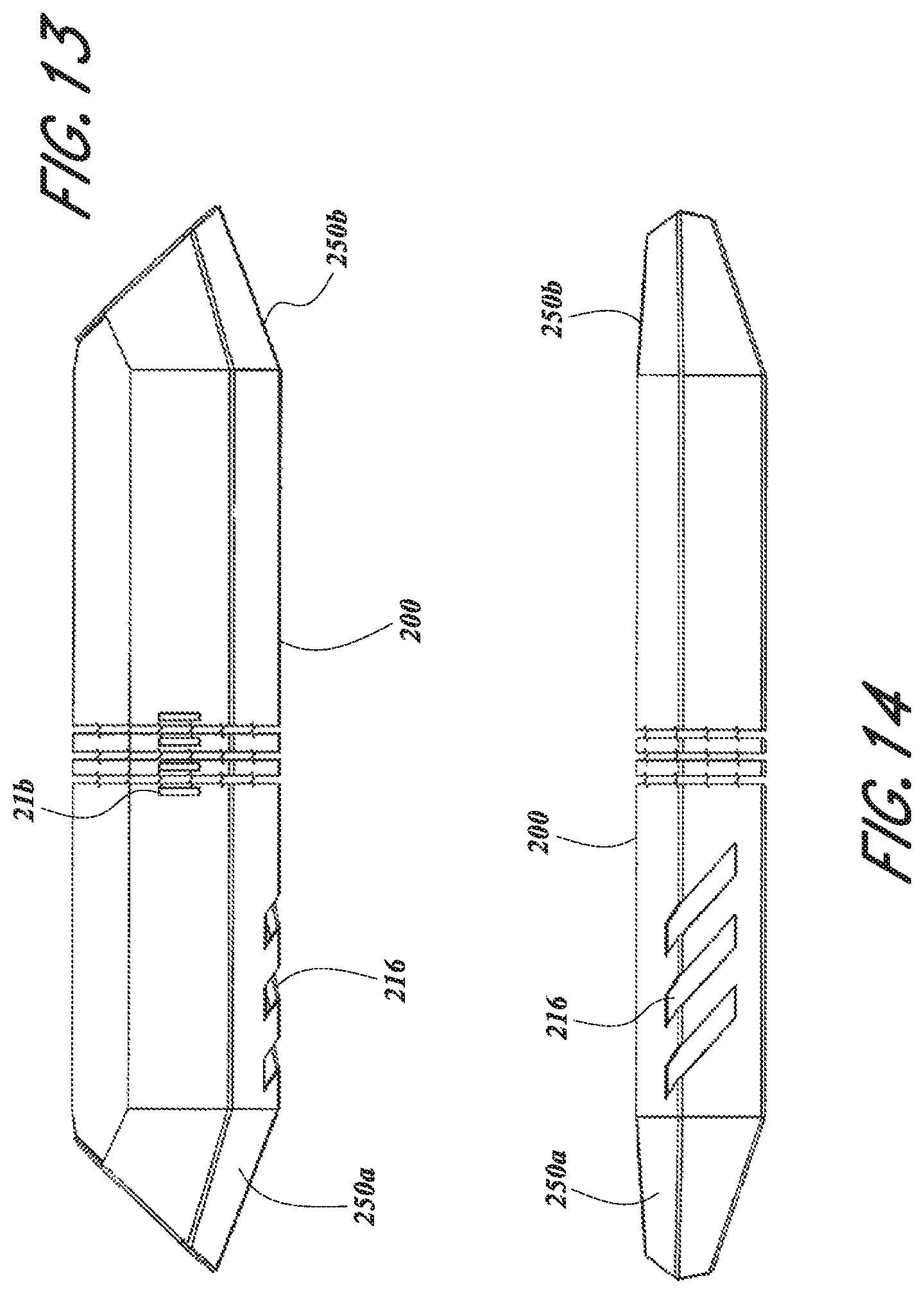
FIG. 13 is a top view of the modular side rail of the system shown in FIG. 1.
FIG. 14 is a side view of the modular side rail of FIG. 13.
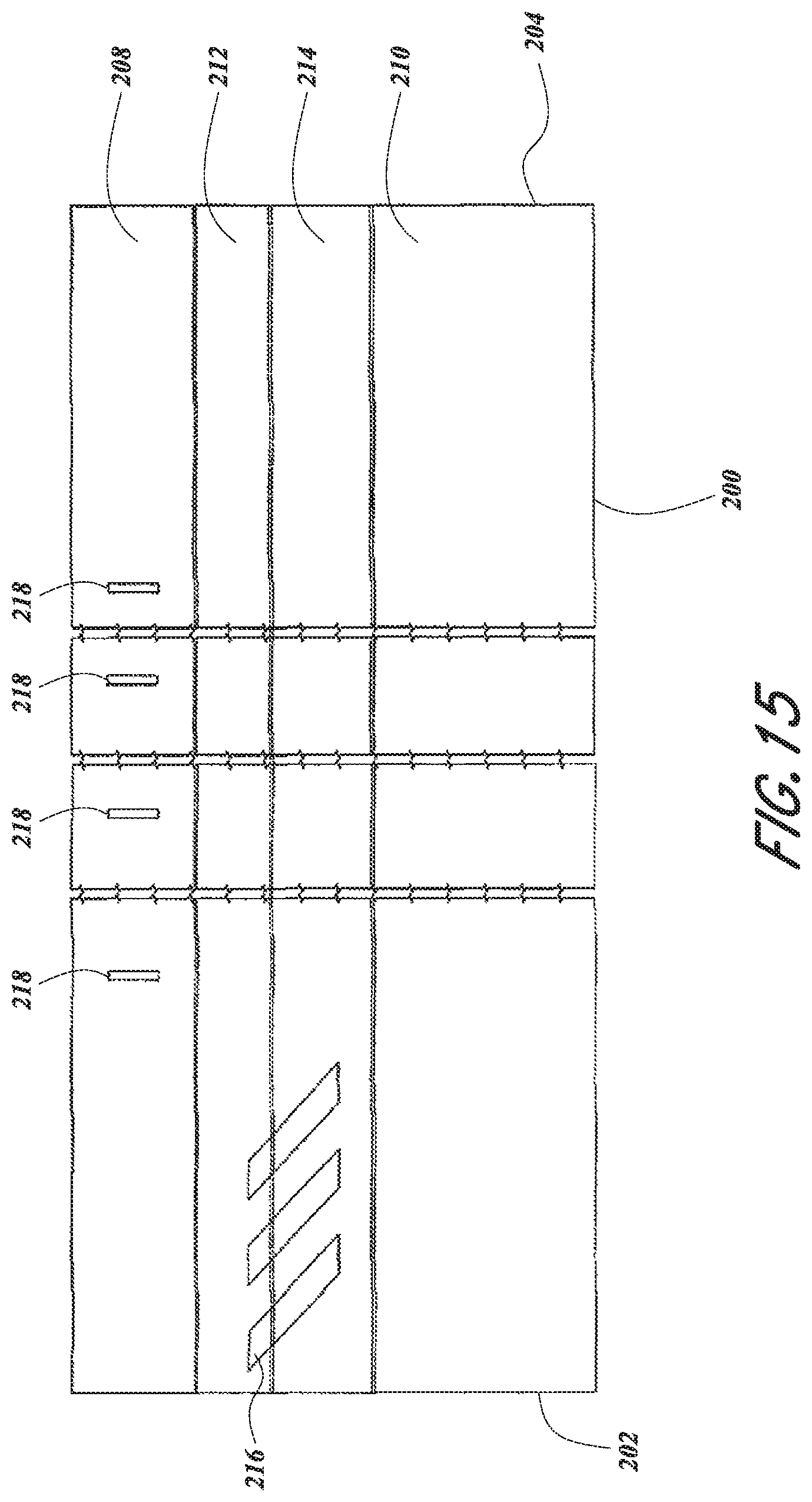
FIG. 15 is a top view of a flat sheet that can be folded to form the modular side rail of FIG. 13.
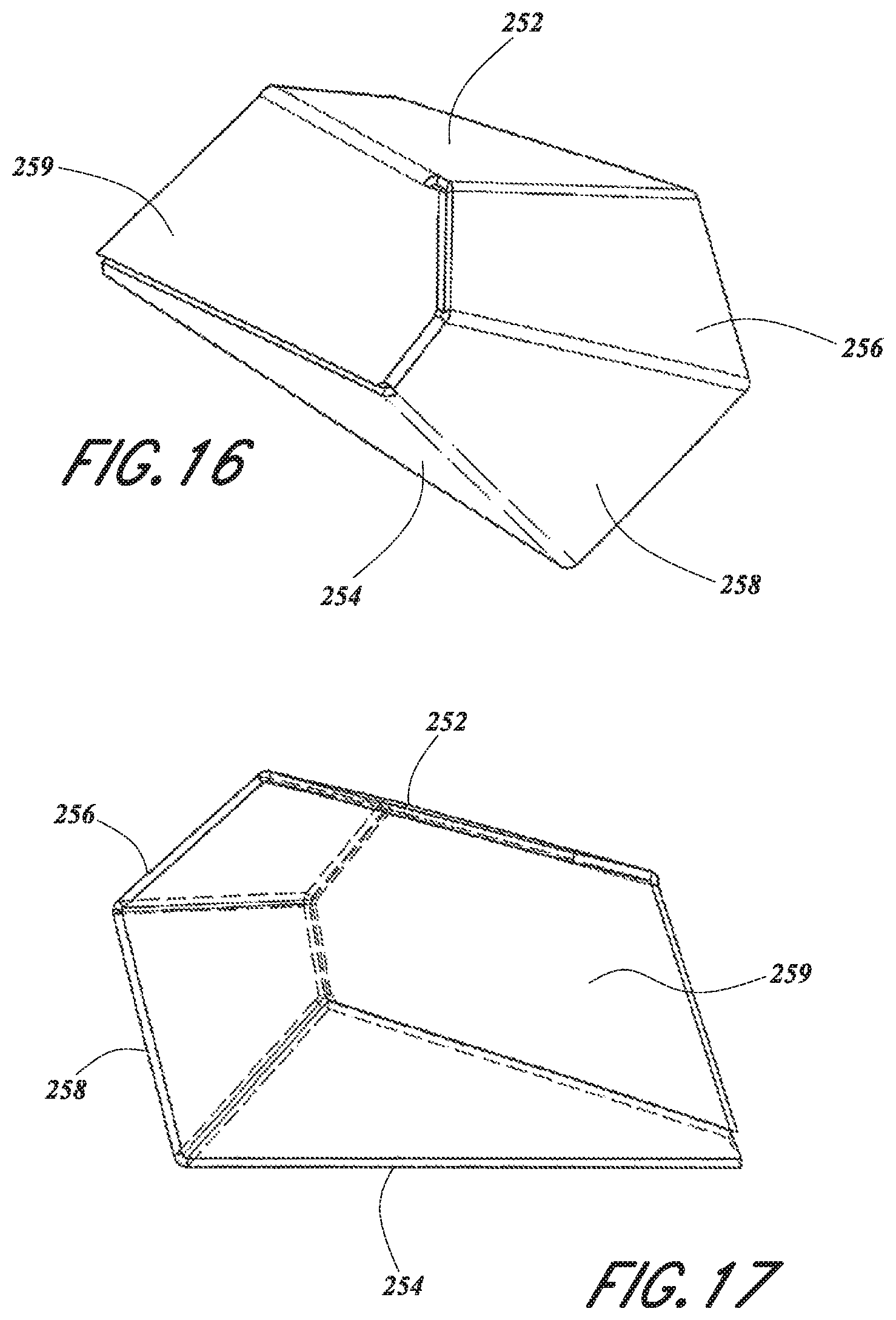
FIG. 16 is a perspective view of an end cap of the modular side rail of FIG. 13.
FIG. 17 is an end view of the end cap of FIG. 16.
FIG. 18 is a top view of a flat sheet that can be folded to form the end cap of FIG. 16.
FIG. 19 is a first side view of the bracket of the system shown in FIG. 1.
FIG. 20 is a top view of the bracket of the system of FIG. 19.
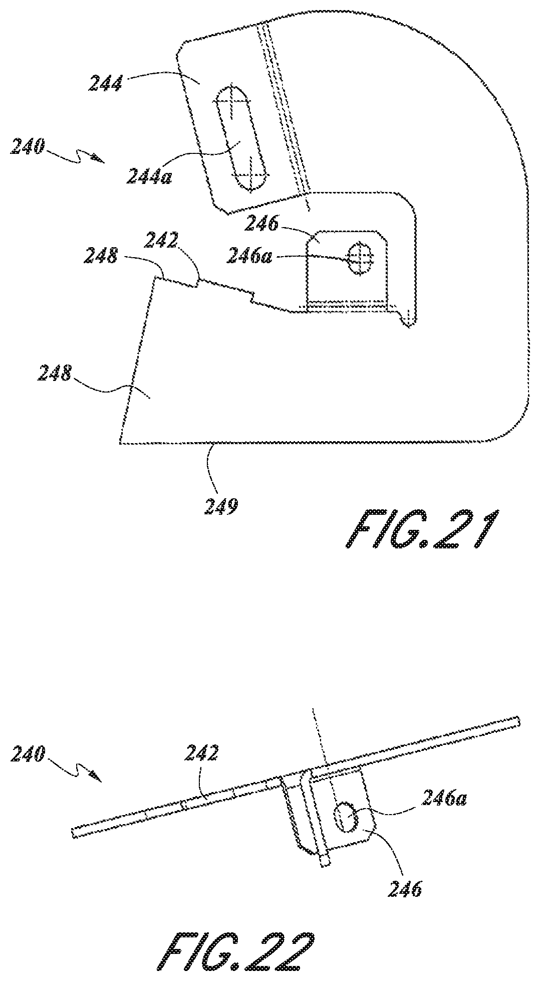
FIG. 21 is a view of a flat sheet that can be folded to form the bracket of the system of FIG. 19.
FIG. 22 is a bottom view of the bracket of the system of FIG. 19.
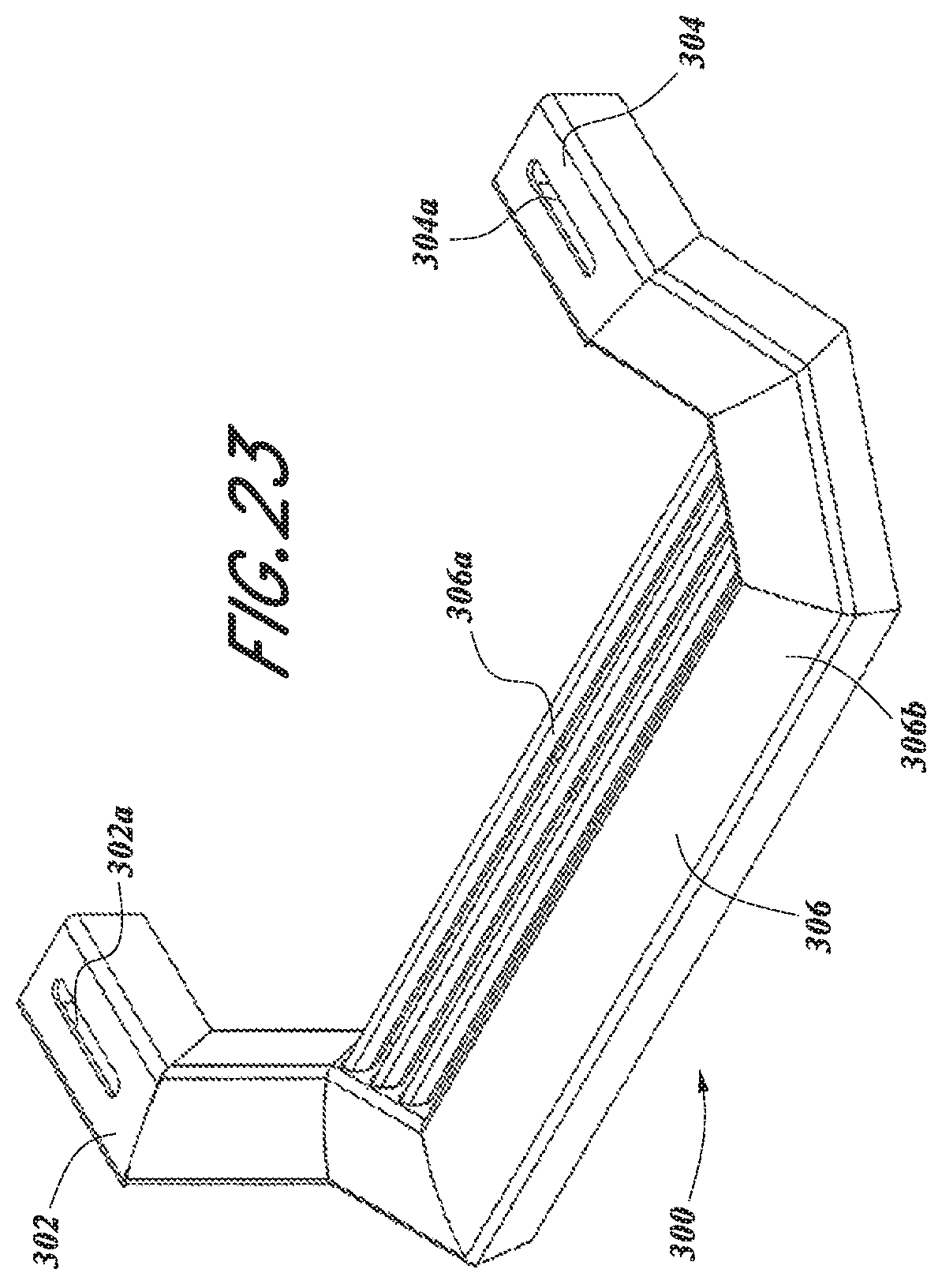
FIG. 23 is a perspective view of one of the step assemblies of the system shown in FIG. 1.
FIG. 24 is a top view of the step assembly of the system shown in FIG. 23.
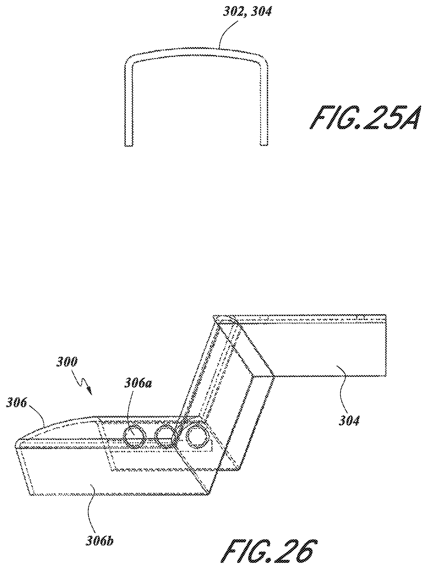
FIG. 25 is a side view of the step assembly of the system shown in FIG. 23.
FIG. 25a is a side view of an arm of the step assembly shown in FIG. 23.
FIG. 26 is an end view of the step assembly of the system shown in FIG. 23.
FIG. 27 is a perspective view of the motor vehicle provided with the modular side rail and step system of FIG. 1 in a second step assembly configuration.
FIG. 28 is a side view of the motor vehicle provided with the modular side rail and step system in the second step assembly configuration of FIG. 27.
FIG. 29 is an enlarged perspective view of a portion of the vehicle provided with the modular side rail and step system in the first step assembly configuration of FIG. 1, as identified at A3 in FIG. 27.
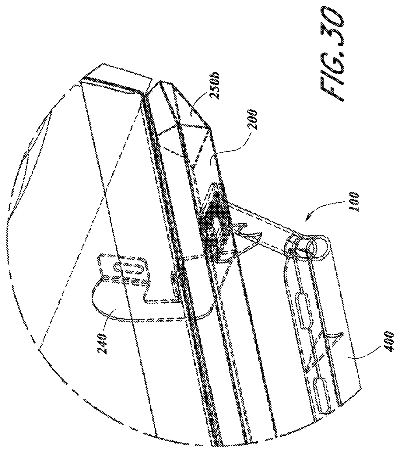
FIG. 30 is an enlarged perspective view of a portion of the vehicle provided with the modular side rail and step system in the second step assembly configuration of FIG. 27, as identified at A4 in FIG. 27.
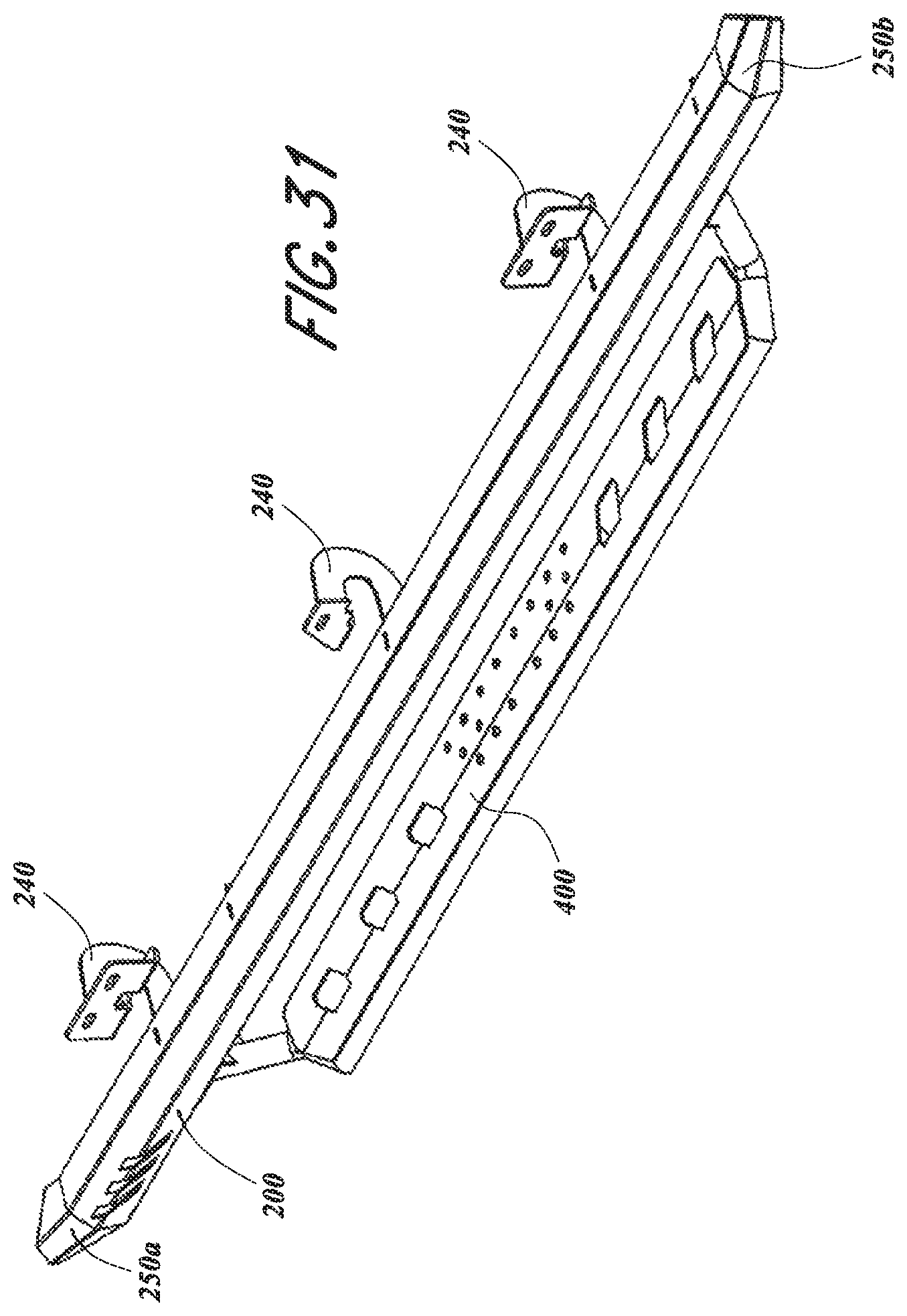
FIG. 31 is a perspective view of the modular side rail and step system in the second step assembly configuration of FIG. 27.
FIG. 32 is a top view of the modular side rail and step system in the second step assembly configuration of FIG. 27.
FIG. 33 is a side view of the modular side rail and step system in the second step assembly configuration of FIG. 27.
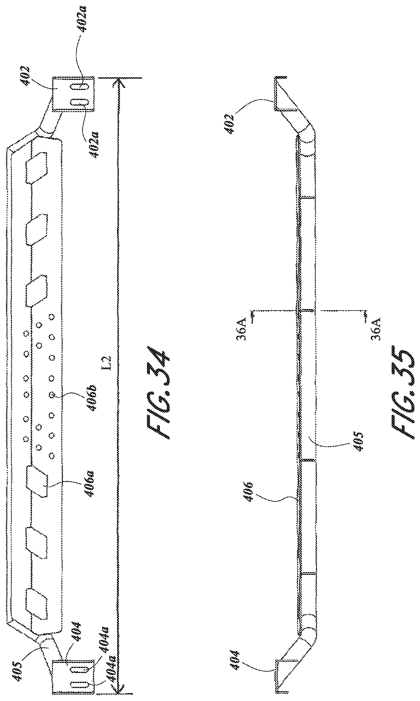
FIG. 34 is a top view of the step assembly of the system shown in FIG. 27.
FIG. 35 is a side view of the step assembly of the system shown in FIG. 34.
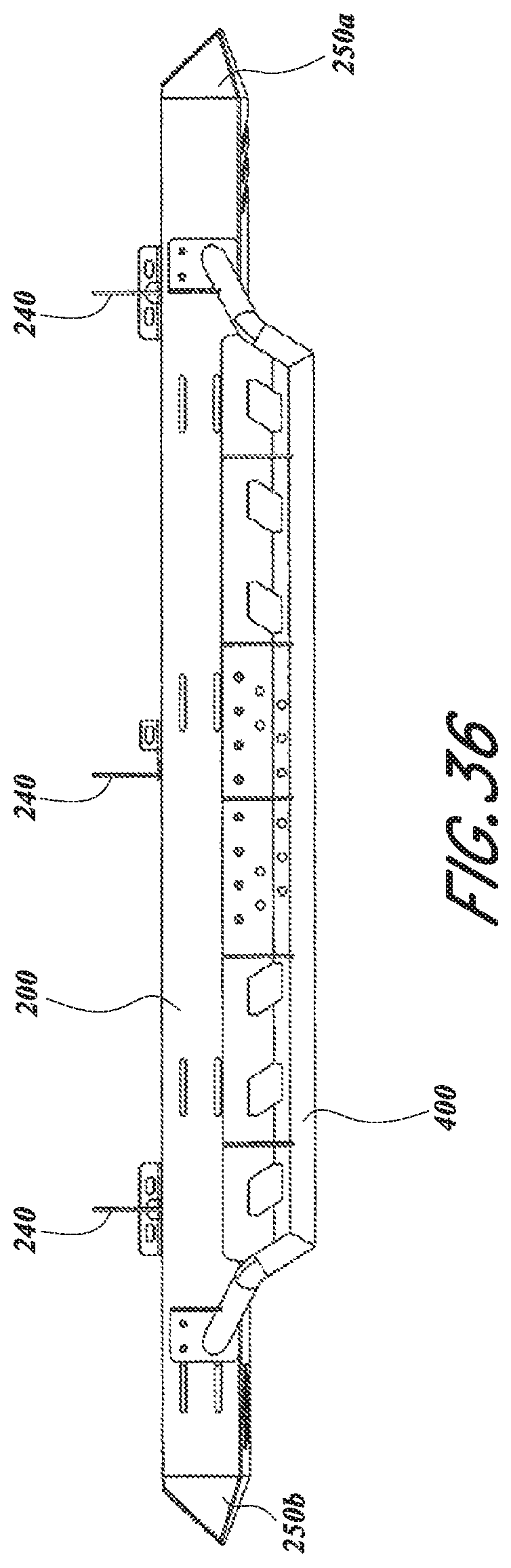
FIG. 36 is a bottom view of the step assembly of the system shown in FIG. 34.
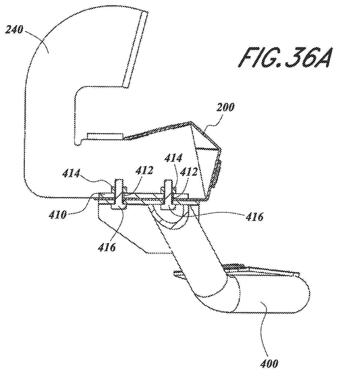
FIG. 36A is a cross-sectional view of the modular side rail and step system in the second step assembly configuration of FIG. 34, taken at a location where a step attaches to the side rail.
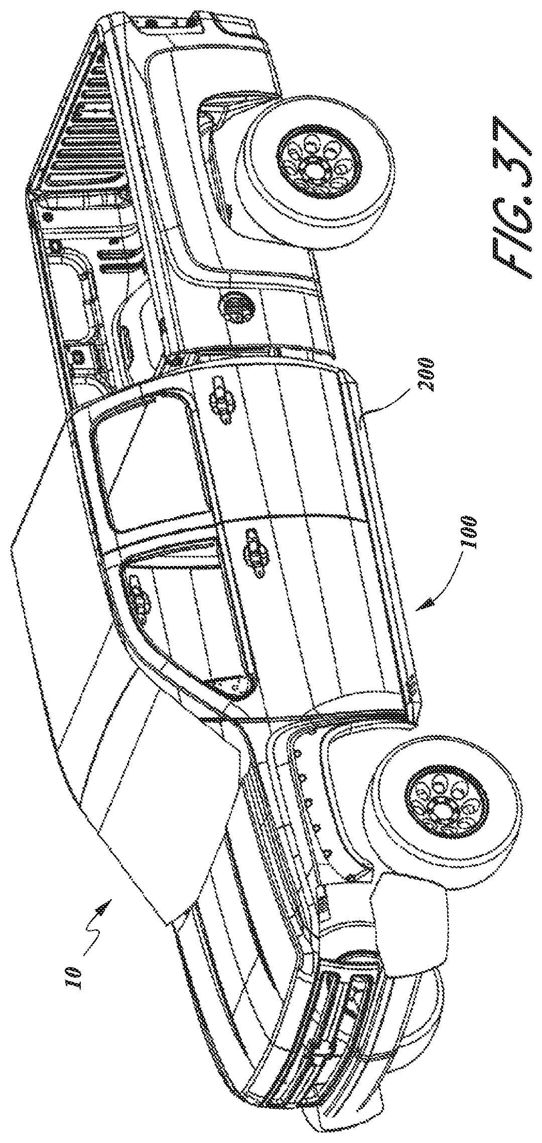
FIG. 37 is a perspective view of the motor vehicle provided with the modular side rail and step system of FIGS. 1 and 27, but without any of the step assemblies installed.
DETAILED DESCRIPTION
Various embodiments will be described in detail with reference to the drawings, wherein like reference numerals represent like parts and assemblies throughout the several views. Reference to various embodiments does not limit the scope of the claims attached hereto. Additionally, any examples set forth in this specification are not intended to be limiting and merely set forth some of the many possible embodiments for the appended claims.
With reference to the Figures, a modular side rail and removable step system 100 for a vehicle 10. As shown, vehicle 10 is a quad-cab pickup truck. However, the system 100 is usable with many other types of vehicles, for example standard cab pickup trucks, extended cab pickup trucks, and sport utility vehicles such as JEEP.RTM. brand vehicles. In one aspect, the modular side rail and removable step system 100 includes a side rail main body 200 configured for mounting to vehicle 10 via mounting brackets 240. In turn, the side rail main body 200 is configured to support one or more removable steps (300, 400) that can be placed in a number of different step assembly configurations. For example, FIG. 1 shows two steps 300a, 300b (collectively referenced as 300) mounted to the side rail main body 200 while FIG. 27 shows an alternative arrangement in which a single, longer step 400 is mounted to the same side rail main body 200. Referring to FIG. 37, a configuration is presented in which no steps are mounted on the side rail main body 200, such as may be desired when additional ground clearance is desired. As, the disclosed modular side rail and removable step system 100 can be provided in a multitude of configurations, a portion or all of the same system 100 may be used on a variety of vehicles. Additionally, the modularity of the system 100 allows a vehicle owner to purchase components of the system separately in order to spread out costs. For example, a vehicle owner may initially purchase only the side rail main body 200 and then later purchase the removable steps 300 or 400. Various aspects of the modular side rail and removable step system 100 are discussed further herein.
The side rail main body 200 may also be provided with one or more apertures or slots 216 for aesthetic purposes and/or to allow for improved mud shedding and easier cleaning. As shown, the side rail main body 200 slots 216 extend across the third and fourth side rail members 212, 214 of the side rail main body 200.
Referring to FIG. 15, it can be seen that the side rail main body 200 may be formed from an initially flat sheet, for example a flat sheet of about 11 gage steel. Other sheet thicknesses may also be used. The side rail main body 200 may be formed by other processes as well, for example by stamping, casting, or extrusion.
The side rail main body 200 may also be provided with apertures or slots 218 configured to receive a tab portion 242 of the mounting brackets 240. As configured, the tab portion 242 extends through the slot 218 at which point the tab portion 242 can be welded to the side rail main body 200 at the point of the slot 218. Other aspects of the mounting brackets 240 and their connection to the side rail main body 200 are discussed in later paragraphs.
In one aspect, the side rail main body 200 extends between a first end 202 and a second end 204 and is formed to have a channel-shape defining a longitudinal opening 206 extending between the first and second ends 202, 204. As shown, the channel shape of the main body 200 is defined by a first side rail member 208, a second side rail member 210, a third side rail member 212, and a fourth side rail member 214, wherein the first and second side rail members 208, 210 define the longitudinal opening 206. While the side rail main body 200 is shown as having four sides 208, 210, 212, 214, more or fewer sides may be used to form the main body 200, for example two sides, three sides, five sides, and six sides.
In one aspect, the first side rail member 208 of the side rail main body 200 is disposed at an obtuse angle with respect to the adjacent third side rail member 212, the third side rail member 212 is disposed at an obtuse angle with respect to the adjacent fourth side rail member 214, the fourth side rail member 214 is disposed at an obtuse angle with respect to the adjacent second side rail member 210, and the first side rail member 208 is disposed at an acute angle with respect to the opposite second side rail member 210. Additionally, when mounted to the vehicle 10, the second side rail member 210 is generally parallel to the ground. However, it should be understood that other angles may be utilized without departing from the concepts presented herein.
As shown, the side rail main body 200 may be provided with a first end cap 250a connected to the first end 202 of the side rail main body 200 and a second end cap 250b connected to the second end 204 of the side rail main body 200. In one aspect, the end caps 250a, 250b (collectively referred to as 250) are mirror images of each other and are shaped to match the cross-sectional profile of the side rail main body. With reference to FIGS. 16-18, each end cap 250 is provided with a first side 252, a second side 254, a third side 256, and a fourth side 258 that correspond to the first through fourth side rail members 208, 210, 212, 214 of the side rail main body 200. Each end cap 250 is additionally provided with a fifth side 259 extending between the first through fourth sides 252, 254, 256, 258 to form a closed structure once the end caps 250a, 250b are attached to the side rail main body 200. In the embodiment shown, the end caps 250 are welded to the side rail main body 200. However, other connections means are certainly possible, such as the use of fasteners. Referring to FIG. 18, it can be seen that the end cap 250 may be formed from an initially flat sheet, for example a flat sheet of 11 gage steel. Other sheet thicknesses may also be used.
As most easily seen at FIG. 8, the second side rail member 210 of the side rail main body 200 is provided with a plurality of step attachment arrangements 230, for example a first step attachment arrangement 231, a second step attachment arrangement 232, a third step attachment arrangement 233, a fourth step attachment arrangement 234, and a fifth step attachment arrangement 235 (collectively and/or generically referred to as step attachment arrangements 230). The step attachment arrangements 230 are arranged and configured to provide attachment locations for enabling removable steps to be mounted in various assembly configurations. In the exemplary embodiment shown, the plurality of attachment arrangements 230 enable the first and second removable steps 300, 400 to be mounted in the first and second step assembly configurations shown in FIGS. 1 and 27, respectively.
Notably, the locations of the step attachment arrangements 230 are offset from the locations of the slots 218, and thus offset from the mounting brackets 240. This arrangement allows for the side bar main body 200 to be mounted to the vehicle 10 while still allowing for the steps 300, 400 to be mounted in a desired position with respect to the vehicle 10. For example, the mounting locations of the step attachment arrangements 230 allow the steps 300, 400 to be positioned and centered below the doors 12, 14 of the vehicle.
As shown, the step attachment arrangements 230 include a number of differently configured mounting apertures that function as through holes for fasteners (not shown) for securing the steps 300, 400 to the side rail main body 200 in the various step assembly configurations. For example, the first step attachment arrangement 231 is provided with a mounting aperture 231a presented as a circular hole and two mounting apertures 231b presented as short slots. The second, third, and fourth step attachment arrangements 232, 233, 234 are shown as being provided as a pair of mounting apertures 232a, 233a, 234a, respectively, in the form of parallel longitudinally extending slots. The fifth step arrangement 235 is shown as including mounting apertures 235a, 235b presented as circular holes and parallel longitudinally extending slots, respectively. Other numbers and shapes of mounting apertures may be utilized for the step attachment arrangements without departing from the concepts presented herein.
In one aspect, the second and third step attachment arrangements 232, 233 are configured to provide attachment locations for the removable step 300a while the fourth and fifth step attachment arrangements 234, 235 provide attachment locations for the removable step 300b in a first step assembly configuration. In another aspect, the first and fifth step attachment arrangements 231, 235 are configured to provide attachment locations for the removable step 400 in a second step assembly configuration. Many other configurations between steps and/or attachment arrangements to result in additional step assembly configurations are possible without departing from the concepts presented herein.
As identified previously, the side rail main body 200 may be mounted to the vehicle 10 by a plurality of spaced mounting brackets 240. The brackets 240 are shown in greater detail at FIGS. 12 and 19-22. As shown, each mounting bracket 240 includes a first and second mounting arrangement 244, 246 including mounting apertures 244a, 246a, respectively. The mounting arrangements 244, 246 are configured to mate with portions of the vehicle body (not shown) and secure the bracket 240 in both a vertical direction and a horizontal direction with respect to the ground. The mounting apertures 244a, 246a are configured to receive fasteners (not shown) that mount to the vehicle 10 to secure the bracket 240 to the vehicle 10. It is noted that the configuration of the first and second mounting arrangements 244, 246 can be adjusted to match the mounting requirements of a particular vehicle.
Each mounting bracket 240 is further provided with an extension portion 247 having a first side 248 and a second side 249. The previously discussed tab portion 242 extends along the first side 248. In one aspect, the extension portion 247 extends through the longitudinal opening 206 of the side bar main body 200 such that the bracket first side 248 is adjacent to the side bar main body first side rail member 208 and such that the tab portion 242 extends through the slot 218 of the main body 200. Additionally, the bracket second side 249 is adjacent to the side bar main body second side rail member 210. Once assembled, the bracket 240 can be secured to the main body 200 by welding or other means along the first side 248, the second side 249, and/or the tab portion 242 of the bracket 240. Accordingly, the brackets 240 are an integral structural component of the side rail assembly such that the brackets 240 and the side bar main body 200 together form a unitary structure. It is noted that the addition of the brackets 240 to the side bar main body 200 significantly increases the stiffness of the main body 200. Because the second side 249 of each bracket 240 is adjacent to and secured to the side bar main body second side rail member 210, the stiffness at the second side rail member 210 is sufficient to allow the side bar main body 200 to function as a true rock rail to protect the vehicle 10 from impacts from below. This construction also allows for sufficient stiffness to support the weight of a person standing on the step during vehicle entry and exiting. The brackets 240 could also be secured to the main body 200 by means other than welding, for example with fasteners such as rivets or bolts.
Referring to FIGS. 23-26, the removable step 300 is shown in further detail. In one aspect, the removable step 300 has a length L1 defined by a first arm 302 and a second arm 304 between which a step portion 306 is presented. As configured, the first arm 302 is provided with a mounting aperture 302a while the second arm 304 is provided with a mounting aperture 304a. The mounting apertures 302a, 302b are presented as extending slots and are configured to align with the step arrangements 230 of the side bar main body 200. In the embodiment shown, the mounting aperture slots 302a, 302b extend in a direction that is orthogonal to the direction of the slots associated with the second, third, fourth and fifth attachment arrangements 232, 233, 234, 235 which allows for the step to be adjusted in two directions: a direction parallel to the length of the side bar main body 200 and a direction orthogonal to the length of the side bar main body 200.
As mentioned previously, the removable step 300 can be removably mounted to the side bar main body 200 via removable fasteners 316, such as bolts. A pinch plate 310 may also be utilized to clamp the second side rail member 210 of the side bar main body 200 on the opposite side of the first and second arms 302, 304 to strengthen the connection between the step 300 and the main body 200, as shown at FIG. 8A. In the embodiment shown, the pinch plate 310 includes apertures 312 that can be aligned with the mounting apertures of the step attachment arrangements such that the fasteners 316 may pass through both the side rail main body 200 and the pinch plate 310. In one aspect, the pinch plate 310 includes a threaded member 314 at each aperture 312, shown herein as a threaded nut welded to the pinch plate, for engaging the fasteners 316.
To further strengthen the step 300, the first and second arms 302, 304 can be provided with a channel-shape, as most easily seen at FIG. 25a. To improve mud shedding and/or aesthetics of the step 300, the step portion 306 may be formed with individually spaced bars 306a extending between a support portion 306b.
Referring to FIGS. 34-35, the removable step 400 is shown in further detail. In one aspect, the removable step 400 has a length L2 defined by a first mounting plate 402 and a second mounting plate 404. A support bar 405 is also provided with step 400 that extends between the mounting plates 402, 404 and also serves to support a step portion 406. As presented, the length L1 of the removable step 300 is less than the length L2 of the removable step 400. As configured, the first arm 402 is provided with mounting apertures 402a while the second arm 404 is provided with mounting apertures 404a. The mounting apertures 402a, 402b are presented as parallel extending slots and are configured to align with the step arrangements 230 of the side bar main body 200. In the embodiment shown, the mounting aperture slots 402a, 402b extend in a direction that is orthogonal to the direction of the slots associated with the first and fifth attachment arrangements 231, 235 which allows for the step to be adjusted in two directions: a direction parallel to the length of the side bar main body 200 and a direction orthogonal to the length of the side bar main body 200. However, adjustment in the direction parallel to the length of the side mar main body 200 of the step 400 is limited where mounting apertures 231a and/or 235a are utilized, as is shown in the drawings.
As mentioned previously, the removable step 400 can be removably mounted to the side bar main body 200 via removable fasteners 416, such as bolts. A pinch plate 410 may also be utilized to clamp the second side rail member 210 of the side bar main body 200 on the opposite side of the first and second mounting plates 402, 404 to strengthen the connection between the step 400 and the main body 200, as shown at FIG. 36A. In the embodiment shown, the pinch plate 410 includes apertures 412 that can be aligned with the mounting apertures of the step attachment arrangements such that the fasteners 416 may pass through both the side rail main body 200 and the pinch plate 410. In one aspect, the pinch plate 410 includes a threaded member 414 at each aperture 412, shown herein as a threaded nut welded to the pinch plate, for engaging the fasteners 416.
To improve mud shedding and/or aesthetics of the step 400, the step portion 406 may be formed with various openings 406a, 406b. As shown, the step portion 406 is welded to the support arm 405. To further strengthen the step 400, the first and second mounting plates 402, 404 can be provided with a channel-shape, as most easily seen at FIG. 35. To improve mud shedding and/or aesthetics of the step 300, the step portion 306 may be formed with individually spaced bars 306a extending between a support portion 306b.
The various embodiments described above are provided by way of illustration only and should not be construed to limit the claims attached hereto. Those skilled in the art will readily recognize various modifications and changes that may be made without following the example embodiments and applications illustrated and described herein, and without departing from the true spirit and scope of the disclosure.
* * * * *
D00000
D00001
D00002
D00003
D00004
D00005
D00006
D00007
D00008
D00009
D00010
D00011
D00012

D00013

D00014
D00015
D00016
D00017
D00018

D00019

D00020
D00021
D00022

D00023
D00024

D00025

D00026

D00027
D00028
D00029

D00030
D00031
D00032
D00033
XML
uspto.report is an independent third-party trademark research tool that is not affiliated, endorsed, or sponsored by the United States Patent and Trademark Office (USPTO) or any other governmental organization. The information provided by uspto.report is based on publicly available data at the time of writing and is intended for informational purposes only.
While we strive to provide accurate and up-to-date information, we do not guarantee the accuracy, completeness, reliability, or suitability of the information displayed on this site. The use of this site is at your own risk. Any reliance you place on such information is therefore strictly at your own risk.
All official trademark data, including owner information, should be verified by visiting the official USPTO website at www.uspto.gov. This site is not intended to replace professional legal advice and should not be used as a substitute for consulting with a legal professional who is knowledgeable about trademark law.