Method of increasing thickness of tube and increased thickness tube
Yamamoto , et al.
U.S. patent number 10,603,712 [Application Number 15/556,747] was granted by the patent office on 2020-03-31 for method of increasing thickness of tube and increased thickness tube. This patent grant is currently assigned to NIPPON STEEL & SUMKIN STAINLESS STEEL CORPORATION. The grantee listed for this patent is NIPPON STEEL & SUMIKIN STAINLESS STEEL CORPORATION. Invention is credited to Mitsuhiro Fujinaga, Junichi Hamada, Atsuhisa Yakawa, Shuji Yamamoto.


| United States Patent | 10,603,712 |
| Yamamoto , et al. | March 31, 2020 |
Method of increasing thickness of tube and increased thickness tube
Abstract
A method of increasing the thickness of a tube which increases a thickness of an end part of a tube without a burr being formed, comprising placing a tube 21 between a die 25 and mandrel 22 in the state with a space for increasing the thickness between a small diameter part 22a of the mandrel 22 and a first end part 21a of a tube 21 and between a large diameter hole part 25C of the die 25 and a second end part 21b of the tube 21, using a first upsetting punch 23 and a second upsetting punch 24 to respectively process the first end part 21a and the second end part 21b of the tube 21, pulling out the mandrel 22 from the tube 31 in the state with the second upsetting punch 24 constraining the second end part 31b of the tube 31, and using the first upsetting punch 23 to push up the first end part 31a of the tube 31 to take out the tube 31 from the die 25.
| Inventors: | Yamamoto; Shuji (Tokyo, JP), Hamada; Junichi (Tokyo, JP), Yakawa; Atsuhisa (Tokyo, JP), Fujinaga; Mitsuhiro (Tokyo, JP) | ||||||||||
|---|---|---|---|---|---|---|---|---|---|---|---|
| Applicant: |
|
||||||||||
| Assignee: | NIPPON STEEL & SUMKIN STAINLESS
STEEL CORPORATION (Tokyo, JP) |
||||||||||
| Family ID: | 56880498 | ||||||||||
| Appl. No.: | 15/556,747 | ||||||||||
| Filed: | March 8, 2016 | ||||||||||
| PCT Filed: | March 08, 2016 | ||||||||||
| PCT No.: | PCT/JP2016/057192 | ||||||||||
| 371(c)(1),(2),(4) Date: | September 08, 2017 | ||||||||||
| PCT Pub. No.: | WO2016/143791 | ||||||||||
| PCT Pub. Date: | September 15, 2016 |
Prior Publication Data
| Document Identifier | Publication Date | |
|---|---|---|
| US 20180056370 A1 | Mar 1, 2018 | |
Foreign Application Priority Data
| Mar 10, 2015 [JP] | 2015-047475 | |||
| Current U.S. Class: | 1/1 |
| Current CPC Class: | B21D 41/026 (20130101); B21J 5/08 (20130101) |
| Current International Class: | B21J 5/00 (20060101); B21J 5/08 (20060101); B21D 41/02 (20060101) |
| Field of Search: | ;72/370.01,370.02,370.03,370.1,370.13,370.14,370.15 |
References Cited [Referenced By]
U.S. Patent Documents
| 1104088 | July 1914 | Wales |
| 4213322 | July 1980 | Barnes, Jr. |
| 5956988 | September 1999 | Beste et al. |
| 7644601 | January 2010 | Brochheuser |
| 2007/0204668 | September 2007 | Shiokawa |
| 102010015834 | Oct 2011 | DE | |||
| 10-507410 | Jul 1998 | JP | |||
| 11-333537 | Dec 1999 | JP | |||
| 2007-275896 | Oct 2007 | JP | |||
Other References
|
Chinese Office Action and Search Report, dated Mar. 1, 2019, for corresponding Chinese Application No. 201680014301.7. cited by applicant . English translation of Chinese Office Action dated Mar. 1, 2019 for Application No. 201680014301.7. cited by applicant . International Search Report for PCT/JP2016/057192 dated Apr. 19, 2016. cited by applicant . Written Opinion of the International Searching Authority for PCT/JP2016/057192 (PCT/ISA/237) dated Apr. 19, 2016. cited by applicant. |
Primary Examiner: Sullivan; Debra M
Assistant Examiner: Kresse; Matthew
Attorney, Agent or Firm: Birch, Stewart, Kolasch & Birch, LLP
Claims
The invention claimed is:
1. A method of increasing a thickness of both end parts of a tube which increases a thickness of an end part of a tube having a first end part and a second end part, said method of increasing the thickness comprising performing: a step of using a mandrel having a small diameter part, a slanted surface part expanded in diameter continuing from said small diameter part, and a large diameter part continuing from said slanted surface part, a die having a small diameter hole part, a slanted hole surface part expanded in hole diameter continuing from said small diameter hole part, and a large diameter hole part continuing from said slanted hole surface part, a first upsetting punch arranged along said small diameter part of said mandrel and said small diameter hole part of said die, and a second upsetting punch arranged along said large diameter part of said mandrel and said large diameter hole part of said die thereby inserting a tube workpiece between said die and said mandrel, swaging said first end part of the tube by said first upsetting punch, and further, swaging said second end part of the tube by said second upsetting punch to increase the thickness of the first end part and the second end part, a step of pulling out said mandrel from said tube in a state with the second upsetting punch constraining the second end part of the tube, and a step of using said first upsetting punch to push up said first end part of said tube to take out said tube from said die to thereby form an increased thickness tube with said first end part increased in thickness to an inner surface side of the tube and with said second end part increased in thickness to an outer surface side of the tube.
Description
TECHNICAL FIELD
The present invention relates to a method of increasing the thickness of a tube which increases the thickness of an end part of a tube and to an increased thickness tube increased in thickness by this.
BACKGROUND ART
As prior art for increasing the thickness of an end part of a tube, for example, there is the one disclosed in PLT 1. In the method of PLT 1, as shown in FIG. 1A, a tube 1 is placed in the middle of an upper die 2 and a lower die 3, then an upsetting punch 4 is pushed against this in the arrow direction to increase the thickness of an end part of the tube 1 as shown in FIG. 1B.
CITATION LIST
Patent Literature
PLT 1: Japanese Patent Publication No. 59-88210A
SUMMARY OF INVENTION
Technical Problem
With the method of PLT 1, two split dies 2 and 3 are used, so after increasing the thicknesses of the two ends, the tube can be removed from the dies 2 and 3 and upsetting punch 4. However, as shown in FIG. 1C, the dies 2 and 3 are formed with chamfered parts 2a and 3a considering the fact that the outer surface of the tube 1 enters into the clearance between the upper die 2 and lower die 3 when increasing the thickness, but there is the problem that a burr is formed at the boundary part of the split dies 2 and 3.
The present invention was made in consideration of the above situation and has as its object to enable an increase of thickness of an end part of a tube without a burr being formed.
Solution to Problem
To achieve the above object, the gist of the method of increasing the thickness of a tube of the present invention is as follows:
A method of increasing the thickness of a tube which increases a thickness of an end part of a tube having a first end part and a second end part, the method of increasing the thickness of a tube comprising using a mandrel having a small diameter part, a slanted surface part expanded in diameter continuing from the small diameter part, and a large diameter part continuing from the slanted surface part, a die having a small diameter hole part, a slanted hole surface part expanded in hole diameter following the small diameter hole part, and a large diameter hole part following the slanted hole surface part, a first upsetting punch arranged along the small diameter part of the mandrel and the small diameter hole part of the die, and a second upsetting punch arranged along the large diameter part of the mandrel and the large diameter hole part of the die so as to place the tube between the die and the mandrel, process the first end part of the tube by the first upsetting punch, and, further, process the second end part of the tube by the second upsetting punch to increase the thickness; pulling out the mandrel from the tube in the state using the second upsetting punch to constrain the second end part of the tube; and using the first upsetting punch to push up the first end part of the tube to take out the tube from the die.
Further, the increased thickness tube of the present invention is an increased thickness tube produced by the method of increasing the thickness of a tube of the present invention, the increased thickness tube characterized by having an end part increased in thickness to an inner surface side and an end part increased in thickness to an outer surface side.
Advantageous Effects of Invention
According to the present invention, it is possible to increase the thickness of an end part of a tube without a burr being formed.
BRIEF DESCRIPTION OF DRAWINGS
FIGS. 1A to 1C are views showing a conventional press die, wherein FIG. 1A is a cross-sectional view showing the state before increasing the thickness, FIG. 1B is a cross-sectional view showing the state after increasing the thickness, and FIG. 1C is a cross-sectional view along the line X-X of FIG. 1A.
FIG. 2 is a cross-sectional view showing the state of a press die according to an embodiment before increasing the thickness.
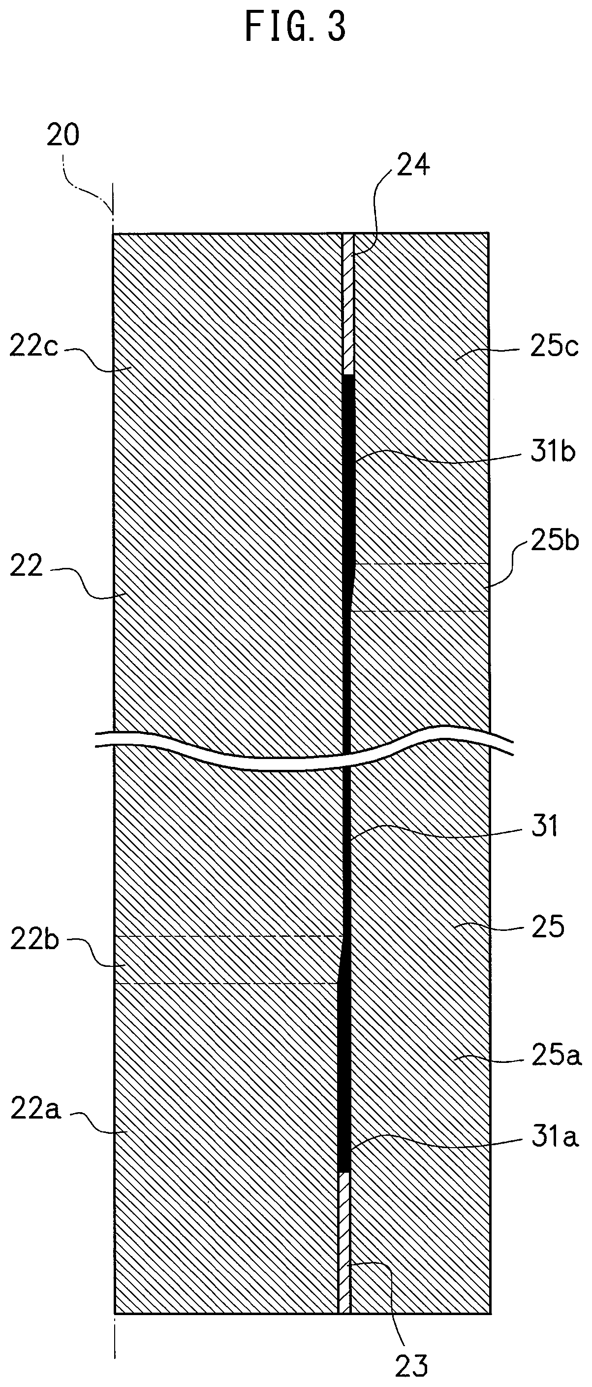
FIG. 3 is a cross-sectional view showing the state of a press die according to an embodiment after increasing the thickness of an end part of a tube.
FIG. 4 is a cross-sectional view showing the state of a press die according to an embodiment after pulling out a mandrel from a tube.
FIG. 5 is a cross-sectional view showing the state of a press die according to an embodiment after pulling out a tube from the die.
DESCRIPTION OF EMBODIMENT
Below, referring to the attached drawings, a preferred embodiment of the present invention will be explained.
FIG. 2 to FIG. 5 are cross-sectional views showing the general outlines of a press die according to the embodiment. The press die is placed in a press machine. Note that the side cross-section of the press die is axially symmetric, so in the figures, only one side part from the center axis 20 is shown.
The press die is comprised of a mandrel 22, first upsetting punch 23, second upsetting punch 24, and die 25 with center axes 20 arranged coaxially. The mandrel 22, first upsetting punch 23, and second upsetting punch 24 are movable types able to be raised and lowered by a not shown lift mechanism, while the die 25 is a fixed type. For the lift mechanism, hydraulics, a servo motor, etc. may be used.
The tube 21 is a tube which has a first end part 21a and a second end part 21b and is constant in wall thickness from one end to the other end. For the tube 21, ordinary steel, stainless steel, aluminum, titanium, or other plastically formable material may be used.
The mandrel 22 has a small diameter part 22a, a slanted surface part 22b of a substantially frustoconical side shape with an expanding diameter continuing from the small diameter part 22a, and a large diameter part 22c continuing from the slanted surface part 22b. The outside diameter of the large diameter part 22c is substantially equal to the inside diameter of the tube 21. The outside diameter of the small diameter part 22a is smaller than the outside diameter of the large diameter part 22c for increasing the thickness of the first end part 21a of the tube 21.
The die 25 has a small diameter hole part 25a, a slanted hole surface part 25b of a substantially frustoconical side shape with an expanding hole diameter continuing from the small diameter hole part 25a, and a large diameter hole part 25c continuing from the slanted hole surface part 25b. The inside diameter of the small diameter hole part 25a is substantially equal to the outside diameter of the tube 21. The inside diameter of the large diameter hole part 25c is larger than the inside diameter of the small diameter hole part 25a for increasing the thickness of the second end part 21b of the tube 21.
The first upsetting punch 23 is arranged along the small diameter part 22a of the mandrel 22 and the small diameter hole part 25a of the die 25 and is substantially cylindrical in shape. The inside diameter of the first upsetting punch 23 is substantially equal to the outside diameter of the small diameter part 22a of the mandrel 22. The outside diameter of the first upsetting punch 23 is substantially equal to the inside diameter of the small diameter hole part 25a of the die 25.
The second upsetting punch 24 is arranged along the large diameter part 22c of the mandrel 22 and the large diameter hole part 25c of the die 25 and is substantially cylindrical in shape. The inside diameter of the second upsetting punch 24 is substantially equal to the outside diameter of the large diameter part 22c of the mandrel 22. The outside diameter of the second upsetting punch 24 is substantially equal to the inside diameter of the large diameter hole part 25c of the die 25.
Below, the operation of increasing the thickness of the tube 21 by the press die according to the present embodiment will be explained.
As shown in FIG. 2, the tube 21 is placed between the die 25 and the mandrel 22. In this state, there are spaces for increasing the thickness between the small diameter part 22a of the mandrel 22 and the first end part 21a of the tube 21 and between the large diameter hole part 25C of the die 25 and the second end part 21b of the tube 21.
Next, as shown in FIG. 3, the first upsetting punch 23 and the second upsetting punch 24 are used to upset the first end part 21a and the second end part 21b of the tube 21 and increase the thickness. The tube after being increased in thickness is assigned reference numeral 31. At the tube 31, the first end part 31a is increased in thickness to the inner surface side, while the second end part 31b is increased in thickness to the outer surface side.
In this case, the first upsetting punch 23 may be used to process the first end part 21a of the tube 21, then the second upsetting punch 24 may be used to process the second end part 21b of the tube 21. Alternatively, the second upsetting punch 24 may be used to process the second end part 21b of the tube 21, then the first upsetting punch 23 may be used to process the end part 21a of the tube 21. Alternatively, the two punches 23 and 24 may be used to simultaneously process the two end parts 21a and 21b of the tube 21.
Next, as shown in FIG. 4, the mandrel 22 is pulled out from the tube 31 in the state with the second upsetting punch 24 constraining the second end part 31b of the tube 31. The second end part 31b of the tube 31 is increased in thickness to the outer surface side (that is, the die 25 side), but is not increased in thickness to the inner surface side (that is, the mandrel 22 side), so the mandrel 22 can be pulled out from the tube 31.
Next, as shown in FIG. 5, the first upsetting punch 23 is used to push up the first end part 31a of the tube 31 to take out the tube 31 from the die 25.
As explained above, by increasing the thickness of one end part to the inner surface side and increasing the thickness of the other end part to the outer surface side, even if using a single-piece die, it becomes possible to take out the tube from the press die after increasing the thickness. When using a single-piece die to increase the thickness of the two ends of the tube to just one of the inner surface side or the outer surface side, it is not possible to take out the tube from the press die after increasing the thickness.
Further, since a single-piece die is used, it is possible to increase the thickness of an end part of the tube without a burr being formed.
The increased thickness tube obtained using the present invention is not particularly limited in application. In particular, the invention is effective when applied to a steel tube used at an exhaust part (for example, a center tube of an exhaust system) of an internal combustion engine (engine) mounted in an automobile, motorcycle, etc. A part used for an automobile or motorcycle is required to be lightened in weight from the viewpoint of the fuel economy efficiency, thermal efficiency, etc. The exhaust tube from the exhaust manifold to the muffler in the parts used for an automobile or motorcycle carries high temperature exhaust gas, so a stainless steel tube excellent in heat resistance and corrosion resistance has been used. Usually, these parts are formed by bending, expanding, or otherwise shaping a steel tube constant in wall thickness, then joining it with other parts. However, from the viewpoint of the heat resistance, corrosion resistance, and structure, each part does not necessarily have to be a steel tube with a constant wall thickness.
Above, the present invention was explained together with an embodiment. The above embodiment only shows a specific example of working the present invention. The technical scope of the present invention must not be interpreted in a limited manner due to these. That is, the present invention can be worked in various ways without departing from its technical idea or main features.
In the above embodiment, an example of increasing the thickness of the two ends of a tube was shown. The present invention also includes increasing the thickness of only one end part to the inner surface side or outer surface side. Further, after increasing the thickness, it is also possible to perform heat treatment or other post-treatment as needed.
REFERENCE SIGNS LIST
20. center axis 21. tube 21a. first end part of tube 21b. second end part of tube 22. mandrel 22a. small diameter part 22b. slanted surface part 22c. large diameter part 23. first upsetting punch 24. second upsetting punch 25. die 25a. small diameter hole part 25b. slanted surface part 25c. large diameter hole part 31. tube after increase of thickness 31a. first end part of tube after increase of thickness 31b. second end part of tube after increase of thickness
* * * * *
D00000
D00001
D00002
D00003
D00004
D00005
XML
uspto.report is an independent third-party trademark research tool that is not affiliated, endorsed, or sponsored by the United States Patent and Trademark Office (USPTO) or any other governmental organization. The information provided by uspto.report is based on publicly available data at the time of writing and is intended for informational purposes only.
While we strive to provide accurate and up-to-date information, we do not guarantee the accuracy, completeness, reliability, or suitability of the information displayed on this site. The use of this site is at your own risk. Any reliance you place on such information is therefore strictly at your own risk.
All official trademark data, including owner information, should be verified by visiting the official USPTO website at www.uspto.gov. This site is not intended to replace professional legal advice and should not be used as a substitute for consulting with a legal professional who is knowledgeable about trademark law.