Handheld electromechanical surgical system
Zergiebel , et al.
U.S. patent number 10,603,128 [Application Number 14/863,558] was granted by the patent office on 2020-03-31 for handheld electromechanical surgical system. This patent grant is currently assigned to COVIDIEN LP. The grantee listed for this patent is Covidien LP. Invention is credited to Matthew Chowaniec, Earl M. Zergiebel.


View All Diagrams
| United States Patent | 10,603,128 |
| Zergiebel , et al. | March 31, 2020 |
Handheld electromechanical surgical system
Abstract
A hand-held electromechanical surgical device configured to selectively connect with a surgical accessory, is provided and includes a handle assembly having a power pack with a core assembly. The core assembly includes a plurality of motors, with each motor having a rotatable drive shaft extending therefrom, wherein each drive shaft is parallel to one another; a processor connected to and configured to control each motor; and a battery electrically connected to the processor and each motor. The power pack includes an inner housing encasing at least the plurality of motors, the processor, and the battery. The handle assembly includes an outer shell housing configured to selectively encase substantially the entire power pack therein, wherein a rotation from each rotatable drive shaft of each motor is transmitted through the inner housing and the outer shell housing.
| Inventors: | Zergiebel; Earl M. (Guilford, CT), Chowaniec; Matthew (Middletown, CT) | ||||||||||
|---|---|---|---|---|---|---|---|---|---|---|---|
| Applicant: |
|
||||||||||
| Assignee: | COVIDIEN LP (Mansfield,
MA) |
||||||||||
| Family ID: | 54260696 | ||||||||||
| Appl. No.: | 14/863,558 | ||||||||||
| Filed: | September 24, 2015 |
Prior Publication Data
| Document Identifier | Publication Date | |
|---|---|---|
| US 20160095585 A1 | Apr 7, 2016 | |
Related U.S. Patent Documents
| Application Number | Filing Date | Patent Number | Issue Date | ||
|---|---|---|---|---|---|
| 62060734 | Oct 7, 2014 | ||||
| Current U.S. Class: | 1/1 |
| Current CPC Class: | A61B 34/74 (20160201); A61B 17/07207 (20130101); A61B 2017/00017 (20130101); A61B 2017/00526 (20130101); A61B 2017/00907 (20130101); A61B 2017/0046 (20130101); A61B 2017/00199 (20130101); A61B 2090/0811 (20160201); A61B 2017/00734 (20130101); A61B 2017/00398 (20130101); A61B 2017/00464 (20130101); A61B 2090/0813 (20160201); A61B 2034/742 (20160201) |
| Current International Class: | A61B 17/072 (20060101); A61B 34/00 (20160101); A61B 17/00 (20060101); A61B 90/00 (20160101) |
References Cited [Referenced By]
U.S. Patent Documents
| 2777340 | January 1957 | Hettwer et al. |
| 2957353 | October 1960 | Babacz |
| 3111328 | November 1963 | Di Rito et al. |
| 3695058 | October 1972 | Keith, Jr. |
| 3734515 | May 1973 | Dudek |
| 3759336 | September 1973 | Marcovitz et al. |
| 4162399 | July 1979 | Hudson |
| 4606343 | August 1986 | Conta et al. |
| 4705038 | November 1987 | Sjostrom et al. |
| 4722685 | February 1988 | de Estrada et al. |
| 4823807 | April 1989 | Russell et al. |
| 4874181 | October 1989 | Hsu |
| 5129118 | July 1992 | Walmesley |
| 5129570 | July 1992 | Schulze et al. |
| 5152744 | October 1992 | Krause et al. |
| 5301061 | April 1994 | Nakada et al. |
| 5312023 | May 1994 | Green et al. |
| 5326013 | July 1994 | Green et al. |
| 5350355 | September 1994 | Sklar |
| 5383874 | January 1995 | Jackson et al. |
| 5383880 | January 1995 | Hooven |
| 5389098 | February 1995 | Tsuruta et al. |
| 5395033 | March 1995 | Byrne et al. |
| 5400267 | March 1995 | Denen et al. |
| 5411508 | May 1995 | Bessler et al. |
| 5413267 | May 1995 | Solyntjes et al. |
| 5427087 | June 1995 | Ito et al. |
| 5433721 | July 1995 | Hooven et al. |
| 5467911 | November 1995 | Tsuruta et al. |
| 5476379 | December 1995 | Disel |
| 5487499 | January 1996 | Sorrentino et al. |
| 5518163 | May 1996 | Hooven |
| 5518164 | May 1996 | Hooven |
| 5526822 | June 1996 | Burbank et al. |
| 5529235 | June 1996 | Boiarski et al. |
| 5535934 | July 1996 | Boiarski et al. |
| 5535937 | July 1996 | Boiarski et al. |
| 5540375 | July 1996 | Bolanos et al. |
| 5540706 | July 1996 | Aust et al. |
| 5542594 | August 1996 | McKean et al. |
| 5549637 | August 1996 | Crainich |
| 5553675 | September 1996 | Pitzen et al. |
| 5562239 | October 1996 | Boiarski et al. |
| 5564615 | October 1996 | Bishop et al. |
| 5609560 | March 1997 | Ichikawa et al. |
| 5626587 | May 1997 | Bishop et al. |
| 5632432 | May 1997 | Schulze et al. |
| 5645209 | July 1997 | Green et al. |
| 5647526 | July 1997 | Green et al. |
| 5653374 | August 1997 | Young et al. |
| 5658300 | August 1997 | Bito et al. |
| 5662662 | September 1997 | Bishop et al. |
| 5667517 | September 1997 | Hooven |
| 5693042 | December 1997 | Boiarski et al. |
| 5704534 | January 1998 | Huitema et al. |
| 5713505 | February 1998 | Huitema |
| 5762603 | June 1998 | Thompson |
| 5779130 | July 1998 | Alesi et al. |
| 5782396 | July 1998 | Mastri et al. |
| 5782397 | July 1998 | Koukline |
| 5792573 | August 1998 | Pitzen et al. |
| 5797536 | August 1998 | Smith et al. |
| 5820009 | October 1998 | Melling et al. |
| 5863159 | January 1999 | Lasko |
| 5908427 | June 1999 | McKean et al. |
| 5954259 | September 1999 | Viola et al. |
| 5964774 | October 1999 | McKean et al. |
| 5993454 | November 1999 | Longo |
| 6010054 | January 2000 | Johnson et al. |
| 6017354 | January 2000 | Culp et al. |
| 6032849 | March 2000 | Mastri et al. |
| 6045560 | April 2000 | McKean et al. |
| 6090123 | July 2000 | Culp et al. |
| 6126651 | October 2000 | Mayer |
| 6129547 | October 2000 | Cise et al. |
| 6165169 | December 2000 | Panescu et al. |
| 6239732 | May 2001 | Cusey |
| 6241139 | June 2001 | Milliman et al. |
| 6264086 | July 2001 | McGuckin, Jr. |
| 6264087 | July 2001 | Whitman |
| 6302311 | October 2001 | Adams et al. |
| 6315184 | November 2001 | Whitman |
| 6321855 | November 2001 | Barnes |
| 6329778 | December 2001 | Culp et al. |
| 6343731 | February 2002 | Adams et al. |
| 6348061 | February 2002 | Whitman |
| 6368324 | April 2002 | Dinger et al. |
| 6371909 | April 2002 | Hoeg et al. |
| 6434507 | August 2002 | Clayton et al. |
| 6443973 | September 2002 | Whitman |
| 6461372 | October 2002 | Jensen et al. |
| 6488197 | December 2002 | Whitman |
| 6491201 | December 2002 | Whitman |
| 6533157 | March 2003 | Whitman |
| 6537280 | March 2003 | Dinger et al. |
| 6610066 | August 2003 | Dinger et al. |
| 6611793 | August 2003 | Burnside et al. |
| 6645218 | November 2003 | Cassidy et al. |
| 6654999 | December 2003 | Stoddard et al. |
| 6698643 | March 2004 | Whitman |
| 6699177 | March 2004 | Wang et al. |
| 6716233 | April 2004 | Whitman |
| 6743240 | June 2004 | Smith et al. |
| 6783533 | August 2004 | Green et al. |
| 6792390 | September 2004 | Burnside et al. |
| 6793652 | September 2004 | Whitman et al. |
| 6817508 | November 2004 | Racenet et al. |
| 6830174 | December 2004 | Hillstead et al. |
| 6846308 | January 2005 | Whitman et al. |
| 6846309 | January 2005 | Whitman et al. |
| 6849071 | February 2005 | Whitman et al. |
| 6860892 | March 2005 | Tanaka et al. |
| 6899538 | May 2005 | Matoba |
| 6905057 | June 2005 | Swayze et al. |
| 6959852 | November 2005 | Shelton, IV et al. |
| 6964363 | November 2005 | Wales et al. |
| 6981628 | January 2006 | Wales |
| 6981941 | January 2006 | Whitman et al. |
| 6986451 | January 2006 | Mastri et al. |
| 6988649 | January 2006 | Shelton, IV et al. |
| 7032798 | April 2006 | Whitman et al. |
| RE39152 | June 2006 | Aust et al. |
| 7055731 | June 2006 | Shelton, IV et al. |
| 7059508 | June 2006 | Shelton, IV et al. |
| 7077856 | July 2006 | Whitman |
| 7111769 | September 2006 | Wales et al. |
| 7122029 | October 2006 | Koop et al. |
| 7140528 | November 2006 | Shelton, IV |
| 7141049 | November 2006 | Stern et al. |
| 7143923 | December 2006 | Shelton, IV et al. |
| 7143925 | December 2006 | Shelton, IV et al. |
| 7143926 | December 2006 | Shelton, IV et al. |
| 7147138 | December 2006 | Shelton, IV |
| 7172104 | February 2007 | Scirica et al. |
| 7225964 | June 2007 | Mastri et al. |
| 7238021 | July 2007 | Johnson |
| 7246734 | July 2007 | Shelton, IV |
| 7252660 | August 2007 | Kunz |
| 7328828 | February 2008 | Ortiz et al. |
| 7364061 | April 2008 | Swayze et al. |
| 7380695 | June 2008 | Doll et al. |
| 7380696 | June 2008 | Shelton, IV et al. |
| 7404508 | July 2008 | Smith et al. |
| 7407078 | August 2008 | Shelton, IV et al. |
| 7416101 | August 2008 | Shelton, IV et al. |
| 7419080 | September 2008 | Smith et al. |
| 7422139 | September 2008 | Shelton, IV et al. |
| 7431189 | October 2008 | Shelton, IV et al. |
| 7441684 | October 2008 | Shelton, IV et al. |
| 7448525 | November 2008 | Shelton, IV et al. |
| 7464846 | December 2008 | Shelton, IV et al. |
| 7464847 | December 2008 | Viola et al. |
| 7464849 | December 2008 | Shelton, IV et al. |
| 7481347 | January 2009 | Roy |
| 7481824 | January 2009 | Boudreaux et al. |
| 7487899 | February 2009 | Shelton, IV et al. |
| 7549564 | June 2009 | Boudreaux |
| 7565993 | July 2009 | Milliman et al. |
| 7568603 | August 2009 | Shelton, IV et al. |
| 7575144 | August 2009 | Ortiz et al. |
| 7588175 | September 2009 | Timm et al. |
| 7588176 | September 2009 | Timm et al. |
| 7637409 | December 2009 | Marczyk |
| 7641093 | January 2010 | Doll et al. |
| 7644848 | January 2010 | Swayze et al. |
| 7670334 | March 2010 | Hueil et al. |
| 7673780 | March 2010 | Shelton, IV et al. |
| 7699835 | April 2010 | Lee et al. |
| 7721931 | May 2010 | Shelton, IV et al. |
| 7738971 | June 2010 | Swayze et al. |
| 7740159 | June 2010 | Shelton, IV et al. |
| 7743960 | June 2010 | Whitman et al. |
| 7758613 | July 2010 | Whitman |
| 7766210 | August 2010 | Shelton, IV et al. |
| 7770773 | August 2010 | Whitman et al. |
| 7770775 | August 2010 | Shelton, IV et al. |
| 7793812 | September 2010 | Moore et al. |
| 7799039 | September 2010 | Shelton, IV et al. |
| 7802712 | September 2010 | Milliman et al. |
| 7803151 | September 2010 | Whitman |
| 7822458 | October 2010 | Webster, III et al. |
| 7845534 | December 2010 | Viola et al. |
| 7845537 | December 2010 | Shelton, IV et al. |
| 7857185 | December 2010 | Swayze et al. |
| 7870989 | January 2011 | Viola et al. |
| 7900805 | March 2011 | Shelton, IV et al. |
| 7905897 | March 2011 | Whitman et al. |
| 7918230 | April 2011 | Whitman et al. |
| 7922061 | April 2011 | Shelton, IV et al. |
| 7922719 | April 2011 | Ralph et al. |
| 7947034 | May 2011 | Whitman |
| 7951071 | May 2011 | Whitman et al. |
| 7954682 | June 2011 | Giordano et al. |
| 7959051 | June 2011 | Smith et al. |
| 7963433 | June 2011 | Whitman et al. |
| 7967178 | June 2011 | Scirica et al. |
| 7967179 | June 2011 | Olson et al. |
| 7992758 | August 2011 | Whitman et al. |
| 8011550 | September 2011 | Aranyi et al. |
| 8016178 | September 2011 | Olson et al. |
| 8016855 | September 2011 | Whitman et al. |
| 8020743 | September 2011 | Shelton, IV |
| 8025199 | September 2011 | Whitman et al. |
| 8035487 | October 2011 | Malackowski |
| 8052024 | November 2011 | Viola et al. |
| 8114118 | February 2012 | Knodel et al. |
| 8127975 | March 2012 | Olson et al. |
| 8132705 | March 2012 | Viola et al. |
| 8152516 | April 2012 | Harvey et al. |
| 8157150 | April 2012 | Viola et al. |
| 8157151 | April 2012 | Ingmanson et al. |
| 8182494 | May 2012 | Yencho et al. |
| 8186555 | May 2012 | Shelton, IV et al. |
| 8186587 | May 2012 | Zmood et al. |
| 8189043 | May 2012 | Schneider |
| 8220367 | July 2012 | Hsu |
| 8235273 | August 2012 | Olson et al. |
| 8241322 | August 2012 | Whitman et al. |
| 8272554 | September 2012 | Whitman et al. |
| 8292150 | October 2012 | Bryant |
| 8292888 | October 2012 | Whitman |
| 8342379 | January 2013 | Whitman et al. |
| 8348130 | January 2013 | Shah et al. |
| 8348855 | January 2013 | Hillely et al. |
| 8353440 | January 2013 | Whitman et al. |
| 8357144 | January 2013 | Whitman et al. |
| 8365633 | February 2013 | Simaan et al. |
| 8365972 | February 2013 | Aranyi et al. |
| 8371492 | February 2013 | Aranyi et al. |
| 8372057 | February 2013 | Cude et al. |
| 8391957 | March 2013 | Carlson et al. |
| 8403926 | March 2013 | Nobis et al. |
| 8418904 | April 2013 | Wenchell et al. |
| 8424739 | April 2013 | Racenet et al. |
| 8454585 | June 2013 | Whitman |
| 8505802 | August 2013 | Viola et al. |
| 8517241 | August 2013 | Nicholas et al. |
| 8523043 | September 2013 | Ullrich et al. |
| 8551076 | October 2013 | Duval et al. |
| 8561871 | October 2013 | Rajappa et al. |
| 8561874 | October 2013 | Scirica |
| 8602287 | December 2013 | Yates et al. |
| 8623000 | January 2014 | Humayun et al. |
| 8627995 | January 2014 | Smith et al. |
| 8632463 | January 2014 | Drinan et al. |
| 8636766 | January 2014 | Milliman et al. |
| 8647258 | February 2014 | Aranyi et al. |
| 8652121 | February 2014 | Quick et al. |
| 8657174 | February 2014 | Yates et al. |
| 8657177 | February 2014 | Scirica et al. |
| 8672206 | March 2014 | Aranyi et al. |
| 8696552 | April 2014 | Whitman |
| 8708213 | April 2014 | Shelton, IV et al. |
| 8715306 | May 2014 | Faller et al. |
| 8758391 | June 2014 | Swayze et al. |
| 8806973 | August 2014 | Ross et al. |
| 8808311 | August 2014 | Heinrich et al. |
| 8820605 | September 2014 | Shelton, IV |
| 8851355 | October 2014 | Aranyi et al. |
| 8858571 | October 2014 | Shelton, IV et al. |
| 8875972 | November 2014 | Weisenburgh, II et al. |
| 8888762 | November 2014 | Whitman |
| 8893946 | November 2014 | Boudreaux et al. |
| 8899462 | December 2014 | Kostrzewski et al. |
| 8905289 | December 2014 | Patel et al. |
| 8919630 | December 2014 | Milliman |
| 8931680 | January 2015 | Milliman |
| 8939344 | January 2015 | Olson et al. |
| 8950646 | February 2015 | Viola |
| 8960519 | February 2015 | Whitman et al. |
| 8961396 | February 2015 | Azarbarzin et al. |
| 8967443 | March 2015 | McCuen |
| 8968276 | March 2015 | Zemlok et al. |
| 8968337 | March 2015 | Whitfield et al. |
| 8992422 | March 2015 | Spivey et al. |
| 9016545 | April 2015 | Aranyi et al. |
| 9023014 | May 2015 | Chowaniec et al. |
| 9033868 | May 2015 | Whitman et al. |
| 9055943 | June 2015 | Zemlok et al. |
| 9064653 | June 2015 | Prest et al. |
| 9072515 | July 2015 | Hall et al. |
| 9113847 | August 2015 | Whitman et al. |
| 9113875 | August 2015 | Viola et al. |
| 9113876 | August 2015 | Zemlok et al. |
| 9113899 | August 2015 | Garrison et al. |
| 9216013 | December 2015 | Scirica et al. |
| 9282961 | March 2016 | Whitman et al. |
| 9282963 | March 2016 | Bryant |
| 9295522 | March 2016 | Kostrzewski |
| 9307986 | April 2016 | Hall et al. |
| 2001/0031975 | October 2001 | Whitman et al. |
| 2002/0049454 | April 2002 | Whitman et al. |
| 2002/0165541 | November 2002 | Whitman |
| 2003/0038938 | February 2003 | Jung et al. |
| 2003/0165794 | September 2003 | Matoba |
| 2004/0111012 | June 2004 | Whitman |
| 2004/0133189 | July 2004 | Sakurai |
| 2004/0153124 | August 2004 | Whitman |
| 2004/0176751 | September 2004 | Weitzner et al. |
| 2004/0193146 | September 2004 | Lee et al. |
| 2005/0125027 | June 2005 | Knodel et al. |
| 2005/0131442 | June 2005 | Yachia et al. |
| 2006/0142656 | June 2006 | Malackowski et al. |
| 2006/0142740 | June 2006 | Sherman et al. |
| 2006/0142744 | June 2006 | Boutoussov |
| 2006/0259073 | November 2006 | Miyamoto et al. |
| 2006/0278680 | December 2006 | Viola et al. |
| 2006/0284730 | December 2006 | Schmid et al. |
| 2007/0023476 | February 2007 | Whitman et al. |
| 2007/0023477 | February 2007 | Whitman et al. |
| 2007/0029363 | February 2007 | Popov |
| 2007/0084897 | April 2007 | Shelton et al. |
| 2007/0102472 | May 2007 | Shelton |
| 2007/0152014 | July 2007 | Gillum et al. |
| 2007/0175947 | August 2007 | Ortiz et al. |
| 2007/0175949 | August 2007 | Shelton et al. |
| 2007/0175950 | August 2007 | Shelton et al. |
| 2007/0175951 | August 2007 | Shelton et al. |
| 2007/0175955 | August 2007 | Shelton et al. |
| 2007/0175961 | August 2007 | Shelton et al. |
| 2007/0270784 | November 2007 | Smith et al. |
| 2008/0029570 | February 2008 | Shelton et al. |
| 2008/0029573 | February 2008 | Shelton et al. |
| 2008/0029574 | February 2008 | Shelton et al. |
| 2008/0029575 | February 2008 | Shelton et al. |
| 2008/0058801 | March 2008 | Taylor et al. |
| 2008/0109012 | May 2008 | Falco et al. |
| 2008/0110958 | May 2008 | McKenna et al. |
| 2008/0147089 | June 2008 | Loh et al. |
| 2008/0167736 | July 2008 | Swayze et al. |
| 2008/0185419 | August 2008 | Smith et al. |
| 2008/0188841 | August 2008 | Tomasello et al. |
| 2008/0197167 | August 2008 | Viola et al. |
| 2008/0208195 | August 2008 | Shores et al. |
| 2008/0237296 | October 2008 | Boudreaux et al. |
| 2008/0251561 | October 2008 | Eades et al. |
| 2008/0255413 | October 2008 | Zemlok et al. |
| 2008/0255607 | October 2008 | Zemlok |
| 2008/0262654 | October 2008 | Omori et al. |
| 2008/0308603 | December 2008 | Shelton et al. |
| 2009/0012533 | January 2009 | Barbagli et al. |
| 2009/0090763 | April 2009 | Zemlok et al. |
| 2009/0099876 | April 2009 | Whitman |
| 2009/0138006 | May 2009 | Bales et al. |
| 2009/0171147 | July 2009 | Lee et al. |
| 2009/0182193 | July 2009 | Whitman et al. |
| 2009/0209990 | August 2009 | Yates et al. |
| 2009/0254094 | October 2009 | Knapp et al. |
| 2009/0299141 | December 2009 | Downey et al. |
| 2010/0023022 | January 2010 | Zeiner et al. |
| 2010/0069942 | March 2010 | Shelton, IV |
| 2010/0193568 | August 2010 | Scheib et al. |
| 2010/0211053 | August 2010 | Ross et al. |
| 2010/0225073 | September 2010 | Porter et al. |
| 2011/0071508 | March 2011 | Duval et al. |
| 2011/0077673 | March 2011 | Grubac et al. |
| 2011/0121049 | May 2011 | Malinouskas et al. |
| 2011/0125138 | May 2011 | Malinouskas |
| 2011/0139851 | June 2011 | McCuen |
| 2011/0155783 | June 2011 | Rajappa et al. |
| 2011/0155786 | June 2011 | Shelton, IV |
| 2011/0172648 | July 2011 | Jeong |
| 2011/0174099 | July 2011 | Ross et al. |
| 2011/0184245 | July 2011 | Xia et al. |
| 2011/0204119 | August 2011 | McCuen |
| 2011/0218522 | September 2011 | Whitman |
| 2011/0276057 | November 2011 | Conlon et al. |
| 2011/0290854 | December 2011 | Timm et al. |
| 2011/0295242 | December 2011 | Spivey et al. |
| 2011/0295269 | December 2011 | Swensgard et al. |
| 2012/0000962 | January 2012 | Racenet et al. |
| 2012/0074199 | March 2012 | Olson et al. |
| 2012/0089131 | April 2012 | Zemlok et al. |
| 2012/0104071 | May 2012 | Bryant |
| 2012/0116368 | May 2012 | Viola |
| 2012/0143002 | June 2012 | Aranyi et al. |
| 2012/0172924 | July 2012 | Allen, IV |
| 2012/0211542 | August 2012 | Racenet |
| 2012/0223121 | September 2012 | Viola et al. |
| 2012/0245428 | September 2012 | Smith et al. |
| 2012/0253329 | October 2012 | Zemlok et al. |
| 2012/0310220 | December 2012 | Malkowski et al. |
| 2012/0323226 | December 2012 | Chowaniec et al. |
| 2012/0330285 | December 2012 | Hartoumbekis et al. |
| 2013/0018361 | January 2013 | Bryant |
| 2013/0093149 | April 2013 | Saur et al. |
| 2013/0181035 | July 2013 | Milliman |
| 2013/0184704 | July 2013 | Beardsley et al. |
| 2013/0184730 | July 2013 | Beardsley |
| 2013/0214025 | August 2013 | Zemlok et al. |
| 2013/0274722 | October 2013 | Kostrzewski et al. |
| 2013/0282052 | October 2013 | Aranyi et al. |
| 2013/0292451 | November 2013 | Viola et al. |
| 2013/0313304 | November 2013 | Shelton, IV et al. |
| 2013/0317486 | November 2013 | Nicholas et al. |
| 2013/0319706 | December 2013 | Nicholas et al. |
| 2013/0324978 | December 2013 | Nicholas et al. |
| 2013/0324979 | December 2013 | Nicholas et al. |
| 2013/0334281 | December 2013 | Williams |
| 2014/0012236 | January 2014 | Williams et al. |
| 2014/0012237 | January 2014 | Pribanic et al. |
| 2014/0012289 | January 2014 | Snow et al. |
| 2014/0025046 | January 2014 | Williams et al. |
| 2014/0110455 | April 2014 | Ingmanson et al. |
| 2014/0207125 | July 2014 | Applegate et al. |
| 2014/0207182 | July 2014 | Zergiebel et al. |
| 2014/0207185 | July 2014 | Goble et al. |
| 2014/0236173 | August 2014 | Scirica et al. |
| 2014/0236174 | August 2014 | Williams et al. |
| 2014/0276932 | September 2014 | Williams et al. |
| 2014/0299647 | October 2014 | Scirica et al. |
| 2014/0303668 | October 2014 | Nicholas et al. |
| 2014/0358129 | December 2014 | Zergiebel et al. |
| 2014/0361068 | December 2014 | Aranyi et al. |
| 2014/0365235 | December 2014 | DeBoer et al. |
| 2014/0373652 | December 2014 | Zergiebel et al. |
| 2015/0014392 | January 2015 | Williams et al. |
| 2015/0048144 | February 2015 | Whitman |
| 2015/0076205 | March 2015 | Zergiebel |
| 2015/0080912 | March 2015 | Sapre |
| 2015/0112381 | April 2015 | Richard |
| 2015/0122870 | May 2015 | Zemlok et al. |
| 2015/0133224 | May 2015 | Whitman et al. |
| 2015/0133957 | May 2015 | Kostrzewski |
| 2015/0150547 | June 2015 | Ingmanson et al. |
| 2015/0150574 | June 2015 | Richard et al. |
| 2015/0157320 | June 2015 | Zergiebel et al. |
| 2015/0157321 | June 2015 | Zergiebel et al. |
| 2015/0164502 | June 2015 | Richard et al. |
| 2015/0201931 | July 2015 | Zergiebel et al. |
| 2015/0272577 | October 2015 | Zemlok et al. |
| 2015/0297199 | October 2015 | Nicholas et al. |
| 2015/0303996 | October 2015 | Calderoni |
| 2015/0320420 | November 2015 | Penna et al. |
| 2015/0327850 | November 2015 | Kostrzewski |
| 2015/0342601 | December 2015 | Williams et al. |
| 2015/0342603 | December 2015 | Zergiebel et al. |
| 2015/0374366 | December 2015 | Zergiebel et al. |
| 2015/0374370 | December 2015 | Zergiebel et al. |
| 2015/0374371 | December 2015 | Richard et al. |
| 2015/0374372 | December 2015 | Zergiebel et al. |
| 2015/0374449 | December 2015 | Chowaniec et al. |
| 2015/0380187 | December 2015 | Zergiebel et al. |
| 2016/0095585 | April 2016 | Zergiebel et al. |
| 2016/0095596 | April 2016 | Scirica et al. |
| 2016/0106406 | April 2016 | Cabrera et al. |
| 2016/0113648 | April 2016 | Zergiebel et al. |
| 2016/0113649 | April 2016 | Zergiebel et al. |
| 2451558 | Jan 2003 | CA | |||
| 2824590 | Apr 2014 | CA | |||
| 102247177 | Nov 2011 | CN | |||
| 102247182 | Nov 2011 | CN | |||
| 103230284 | Aug 2013 | CN | |||
| 102008053842 | May 2010 | DE | |||
| 0705571 | Apr 1996 | EP | |||
| 1769754 | Apr 2007 | EP | |||
| 2055243 | May 2009 | EP | |||
| 2316345 | May 2011 | EP | |||
| 2333509 | Jun 2011 | EP | |||
| 2668910 | Dec 2013 | EP | |||
| 2759268 | Jul 2014 | EP | |||
| 2333509 | Feb 2010 | ES | |||
| 08-038488 | Feb 1996 | JP | |||
| 2005-125075 | May 2005 | JP | |||
| 2011218164 | Nov 2011 | JP | |||
| 2013144108 | Jul 2013 | JP | |||
| 2014140749 | Aug 2014 | JP | |||
| 20120022521 | Mar 2012 | KR | |||
| 2007/014355 | Feb 2007 | WO | |||
| 2011/108840 | Sep 2011 | WO | |||
| 2012/040984 | Apr 2012 | WO | |||
Other References
|
Extended European Search Report corresponding to counterpart Int'l Appln. No. EP 15 18 8539.9, dated Feb. 17, 2016. cited by applicant . Extended European Search Report corresponding to International Application No. EP 15 15 1076.5 dated Apr. 22, 2015. cited by applicant . Japanese Office Action corresponding to International Application No. JP 2011-084092 dated Jan. 14, 2016. cited by applicant . Extended European Search Report corresponding to International Application No. EP 12 19 7970.2 dated Jan. 28, 2016. cited by applicant . Chinese Office Action corresponding to International Application No. CN 201210560638.1 dated Oct. 21, 2015. cited by applicant . European Office Action corresponding to International Application No. EP 14 15 9056.2 dated Oct. 26, 2015. cited by applicant . Australian Examination Report No. 1 corresponding to International Application No. AU 2015200153 dated Dec. 11, 2015. cited by applicant . Australian Examination Report No. 1 corresponding to International Application No. AU 2014204542 dated Jan. 7, 2016. cited by applicant . Chinese Office Action corresponding to International Application No. CN 201310125449.6 dated Feb. 3, 2016. cited by applicant . Extended European Search Report corresponding to International Application No. EP 15 19 0245.9 dated Jan. 28, 2016. cited by applicant . Extended European Search Report corresponding to International Application No. EP 15 16 7793.7 dated Apr. 5, 2016. cited by applicant . European Office Action corresponding to International Application No. EP 14 18 4882.0 dated Apr. 25, 2016. cited by applicant . Extended European Search Report corresponding to International Application No. EP 14 19 6704.2 dated Sep. 24, 2015. cited by applicant . Extended European Search Report corresponding to International Application No. EP 14 19 7563.1 dated Aug. 5, 2015. cited by applicant . Partial European Search Report corresponding to International Application No. EP 15 19 0643.5 dated Feb. 26, 2016. cited by applicant . Extended European Search Report corresponding to International Application No. EP 15 16 6899.3 dated Feb. 3, 2016. cited by applicant . Extended European Search Report corresponding to International Application No. EP 14 19 9783.3 dated Dec. 22, 2015. cited by applicant . Extended European Search Report corresponding to International Application No. EP 15 17 3807.7 dated Nov. 24, 2015. cited by applicant . Extended European Search Report corresponding to International Application No. EP 15 19 0760.7 dated Apr. 1, 2016. cited by applicant . Extended European Search Report corresponding to International Application No. EP 15 17 3803.6 dated Nov. 24, 2015. cited by applicant . Extended European Search Report corresponding to International Application No. EP 15 17 3804.4 dated Nov. 24, 2015. cited by applicant . Extended European Search Report corresponding to International Application No. EP 15 17 3910.9 dated Nov. 13, 2015. cited by applicant . European Office Action corresponding to International Application No. EP 14 15 2236.7 dated Aug. 11, 2015. cited by applicant . Extended European Search Report corresponding to International Application No. EP 15 18 4915.5 dated Jan. 5, 2016. cited by applicant . International Search Report and Written Opinion corresponding to counterpart Int'l Appn. No. PCT/US2015/051837, dated Dec. 21, 2015. cited by applicant . European Communication dated May 3, 2017, corresponding to European Application No. 15 188 539.9; 5 total pages. cited by applicant . Extended European Search Report corresponding to counterpart International Application No. EP 14 18 4882.0 dated May 12, 2015. cited by applicant . Canadian Office Action corresponding to counterpart International Application No. CA 2640399 dated May 7, 2015. cited by applicant . Japanese Office Action corresponding to counterpart International Application No. JP 2011-197365 dated Mar. 23, 2015. cited by applicant . Japanese Office Action corresponding to counterpart International Application No. JP 2011-084092 dated May 20, 2015. cited by applicant . Japanese Office Action corresponding to counterpart International Application No. JP 2014-148482 dated Jun. 2, 2015. cited by applicant . Extended European Search Report corresponding to counterpart International Application No. EP 14 18 9358.6 dated Jul. 8, 2015. cited by applicant . Extended European Search Report corresponding to counterpart International Application No. EP 14 19 6148.2 dated Apr. 23, 2015. cited by applicant . Partial European Search Report corresponding to counterpart International Application No. EP 14 19 6704.2 dated May 11, 2015. cited by applicant . Australian Office Action corresponding to counterpart International Application No. AU 2010241367 dated Aug. 20, 2015. cited by applicant . Partial European Search Report corresponding to counterpart International Application No. EP 14 19 9783.3 dated Sep. 3, 2015. cited by applicant . Extended European Search Report corresponding to counterpart International Application No. EP 15 16 9962.6 dated Sep. 14, 2015. cited by applicant . European Search Report, dated Apr. 5, 2018, corresponding to European Application No. 18151691.5; 10 pages. cited by applicant . Chinese Office Action dated Dec. 5, 2018 (with English translation), corresponding to Chinese Application No. 201510807574.4; 17 total pages. cited by applicant . Jung et al., "Protection DX suppresses hepatic gluconeogenesis through AMPK-HO-1-mediated inhibition of ER stress," Cellular Signalling, (2017), vol. 24; pp. 133-140. cited by applicant . Japanese Office Action (with English translation), dated Apr. 25, 2019, corresponding to counterpart Japanese Application No. 2015-198207; 7 total pages. cited by applicant . Australian Examination Report dated May 20, 2019, corresponding to counterpart Australian Application No. 2015234382; 3 pages. cited by applicant. |
Primary Examiner: Kahelin; Michael W
Assistant Examiner: Sahand; Sana
Attorney, Agent or Firm: Carter, DeLuca & Farrell, LLP
Parent Case Text
CROSS-REFERENCE TO RELATED APPLICATIONS
This application claims the benefit of and priority to U.S. Provisional Patent Application No. 62/060,734 filed Oct. 7, 2014, the entire disclosure of which is incorporated by reference herein.
Claims
What is claimed is:
1. A hand-held electromechanical surgical device configured to selectively connect with a surgical accessory, the electromechanical surgical device, comprising: a handle assembly including: a power pack including: a core assembly having a plurality of motors, with each motor having a rotatable drive shaft extending therefrom, wherein each drive shaft is parallel to one another; and an inner housing encasing at least the plurality of motors and including at least one control interface actuatable to control a functionality of at least one of the plurality of motors; an outer shell housing including first and second sections cooperatively defining a cavity configured to selectively receive the power pack therein, the second section having a connecting portion, the connecting portion having a wall and inner side surfaces that cooperatively define a recess for receipt of a drive coupling assembly of an adapter assembly; and a barrier plate assembly disposed proximally of the wall of the connecting portion of the second section of the outer shell housing and distally of the inner housing of the power pack, wherein a rotation from each rotatable drive shaft of each motor is transmitted through the inner housing and the outer shell via the barrier plate assembly, and wherein the outer shell housing includes at least one control button in operative registration with each control interface of the power pack; wherein actuation of the at least one control button acts on the at least one control interface that is in operative registration therewith to control the functionality of the at least one of the plurality of motors.
2. The electromechanical surgical device according to claim 1, further comprising: an adapter assembly selectively connectable to the handle assembly, the adapter assembly including: a housing configured and adapted to be in operative communication with each rotatable drive shaft; an outer tube having a proximal end supported by the housing and a distal end configured and adapted for selective connection with a loading unit, wherein the distal end of the outer tube is in operative communication at least one axially translatable drive member of the loading unit; and at least one drive shaft configured to interconnect a respective one drive shaft of the handle assembly and a respective one axially translatable drive member of the loading unit.
3. The electromechanical surgical device according to claim 1, wherein the barrier plate assembly includes and supports at least one rotatable coupling shaft; each coupling shaft including a proximal end configured to receive rotative forces from a respective rotatable drive shaft of the handle assembly, and a distal end projecting from the handle assembly.
4. The electromechanical surgical device according to claim 1, wherein the handle assembly supports at least one electrical connector that is in electrical communication with a processor of the core assembly.
5. The electromechanical surgical device according to claim 4, wherein the barrier plate assembly overlies the at least one electrical connector of the handle assembly when the power pack is encased in the outer shell housing.
6. The electromechanical surgical device according to claim 5, wherein the barrier plate assembly includes and supports a pass-through electrical connector, wherein the pass-through electrical connector interfaces with the at least one electrical connector of the handle assembly when the power pack is encased in the outer shell housing.
7. The electromechanical surgical device according to claim 6, wherein the pass-through electrical connector of the barrier plate assembly is received in a window formed in the outer shell housing when the barrier plate assembly is positioned in the outer shell housing.
8. The electromechanical surgical device according to claim 1, wherein at least an outer surface of the outer shell housing is sterile.
9. The electromechanical surgical device according to claim 1, wherein the barrier plate assembly is sterile.
10. The electromechanical surgical device according to claim 3, further comprising: an adapter assembly selectively connectable to the handle assembly, the adapter assembly including: a housing configured and adapted to be in operative communication with each rotatable drive shaft; an outer tube having a proximal end supported by the housing and a distal end configured and adapted for selective connection with a loading unit, wherein the distal end of the outer tube is in operative communication at least one axially translatable drive member of the loading unit; and at least one drive shaft for interconnecting the distal end of a respective one rotatable coupling shaft of the barrier plate assembly.
11. The electromechanical surgical device according to claim 10, wherein the at least one drive shaft of the adapter assembly interconnects with a respective coupling shaft of the barrier plate assembly when the adapter assembly is connected to the handle assembly.
12. The electromechanical surgical device according to claim 11, wherein the handle assembly supports at least one electrical connector that is in electrical communication with a processor of the core assembly.
13. The electromechanical surgical device according to claim 12, wherein the barrier plate assembly overlies the at least one electrical connector of the handle assembly when the power pack is encased in the outer shell housing.
14. The electromechanical surgical device according to claim 13, wherein the barrier plate assembly includes and supports a pass-through electrical connector, wherein the pass-through electrical connector interfaces with the at least one electrical connector of the handle assembly when the power pack is encased in the outer shell housing.
15. The electromechanical surgical device according to claim 14, wherein the adapter assembly includes an electrical assembly having a plurality of electrical contact blades for electrical connection to the pass-through connector of the barrier plate assembly when the adapter assembly is connected to the handle assembly.
16. The electromechanical surgical device according to claim 14, wherein the pass-through electrical connector of the barrier plate assembly is received in a window formed in the outer shell housing when the barrier plate assembly is positioned in the outer shell housing.
17. The electromechanical surgical device according to claim 10, wherein at least an outer surface of the outer shell housing is sterile.
18. The electromechanical surgical device according to claim 17, wherein the barrier plate assembly is sterile.
19. The electromechanical surgical device according to claim 1, wherein the handle assembly includes an electrical display electrically connected to a processor of the core assembly.
20. The electromechanical surgical device according to claim 19, wherein the inner housing includes a window through which the electrical display is visible.
21. The electromechanical surgical device according to claim 19, wherein at least a portion of the inner housing is transparent, wherein the transparent portion of the inner housing is in visual registration with the electrical display.
22. The electromechanical surgical device according to claim 20, wherein the outer shell housing includes a window through which the electrical display is visible, when the handle assembly is encased in the outer shell housing.
23. The electromechanical surgical device according to claim 22, wherein at least a portion of the outer shell housing is transparent, wherein the transparent portion of the outer shell housing is in visual registration with the electrical display.
24. The electromechanical surgical device according to claim 1, wherein the power pack further includes a control plate disposed adjacent to the barrier plate assembly.
25. The electromechanical surgical device according to claim 24, wherein the barrier plate assembly further includes a plate supporting the at least one coupling shaft.
26. The electromechanical surgical device according to claim 25, wherein the at least one coupling shaft extends through the plate.
27. The electromechanical surgical device according to claim 26, wherein the at least one coupling shaft extends within the connecting portion.
Description
BACKGROUND
1. Technical Field
The present disclosure relates to surgical devices. More specifically, the present disclosure relates to handheld electromechanical surgical systems for performing surgical procedures.
2. Background of Related Art
One type of surgical device is a linear clamping, cutting and stapling device. Such a device may be employed in a surgical procedure to resect a cancerous or anomalous tissue from a gastro-intestinal tract. Conventional linear clamping, cutting and stapling instruments include a pistol grip-styled structure having an elongated shaft and distal portion. The distal portion includes a pair of scissors-styled gripping elements, which clamp the open ends of the colon closed. In this device, one of the two scissors-styled gripping elements, such as the anvil portion, moves or pivots relative to the overall structure, whereas the other gripping element remains fixed relative to the overall structure. The actuation of this scissoring device (the pivoting of the anvil portion) is controlled by a grip trigger maintained in the handle.
In addition to the scissoring device, the distal portion also includes a stapling mechanism. The fixed gripping element of the scissoring mechanism includes a staple cartridge receiving region and a mechanism for driving the staples up through the clamped end of the tissue against the anvil portion, thereby sealing the previously opened end. The scissoring elements may be integrally formed with the shaft or may be detachable such that various scissoring and stapling elements may be interchangeable.
A number of surgical device manufacturers have developed product lines with proprietary powered drive systems for operating and/or manipulating the surgical device. In many instances the surgical devices include a powered handle assembly, which is reusable, and a disposable end effector or the like that is selectively connected to the powered handle assembly prior to use and then disconnected from the end effector following use in order to be disposed of or in some instances sterilized for re-use.
Many of the existing end effectors for use with many of the existing powered surgical devices and/or handle assemblies are driven by a linear force. For examples, end effectors for performing endo-gastrointestinal anastomosis procedures, end-to-end anastomosis procedures and transverse anastomosis procedures, each typically require a linear driving force in order to be operated. As such, these end effectors are not compatible with surgical devices and/or handle assemblies that use a rotary motion to deliver power or the like.
In order to make the linear driven end effectors compatible with powered surgical devices and/or handle assemblies that use a rotary motion to deliver power, a need exists for adapters and/or adapter assemblies to interface between and interconnect the linear driven end effectors with the powered rotary driven surgical devices and/or handle assemblies.
It is desirable for these adapters and/or adapter assemblies to selectively connect/re-connect with the underlying powered surgical devices and/or handle assemblies via a quick-connect/quick-disconnect mechanism.
Accordingly, a need exists for adapters and/or adapter assemblies, and underlying powered surgical devices and/or handle assemblies including complementary quick-connect/quick-disconnect mechanisms.
SUMMARY
The present disclosure relates to electromechanical surgical devices for performing surgical procedures.
According to an aspect of the present disclosure, a hand-held electromechanical surgical device configured to selectively connect with a surgical accessory, is provided. The electromechanical surgical device includes a handle assembly. The handle assembly includes a power pack having a core assembly. The core assembly includes a plurality of motors, with each motor having a rotatable drive shaft extending therefrom, wherein each drive shaft is parallel to one another; a processor connected to and configured to control each motor; and a battery electrically connected to the processor and each motor.
The power pack includes an inner housing encasing at least the plurality of motors, the processor, and the battery, the inner housing including at least one control interface actuatable to control a functionality of at least one of the plurality of motors.
The handle assembly includes an outer shell housing configured to selectively encase substantially the entire power pack therein, wherein a rotation from each rotatable drive shaft of each motor is transmitted through the inner housing and the outer shell housing, and wherein the outer shell housing includes at least one control button in operative registration with each control interface of the power pack.
In use, actuation of the at least one control button acts on the at least one control interface that is in operative registration therewith to control the functionality of the at least one of the plurality of motors.
The electromechanical surgical device may further include an adapter assembly selectively connectable to the handle assembly. The adapter assembly may include a housing configured and adapted for connection with the surgical device and to be in operative communication with each rotatable drive shaft; an outer tube having a proximal end supported by the housing and a distal end configured and adapted for selective connection with a loading unit, wherein the distal end of the outer tube is in operative communication at least one axially translatable drive member of the loading unit; and at least one force/rotation transmitting/converting assembly for interconnecting a respective one drive shaft of the surgical device and a respective one axially translatable drive member of the loading unit.
The electromechanical surgical device may further include a barrier plate assembly interposed between the power pack and the outer shell housing. The barrier plate assembly may include and may support at least one rotatable coupling shaft. Each coupling shaft may include a proximal end configured to receive rotative forces from a respective rotatable drive shaft, and a distal end projecting from the handle assembly.
The at least one force/rotation transmitting/converting assembly of the adapter assembly may interconnect with a respective coupling shaft of the barrier plate assembly when the adapter assembly is connected to the handle assembly.
The handle assembly may support at least one electrical connector that is in electrical communication with the processor.
The barrier plate assembly may overlie the electrical connector of the handle assembly when the power pack is encased in the outer shell housing.
The barrier plate assembly may include and may support a pass-through electrical connector, wherein the pass-through electrical connector may interface with the electrical connector of the handle assembly when the power pack is encased in the outer shell housing.
The adapter assembly may include an electrical assembly having a plurality of electrical contact blades for electrical connection to the pass-through connector of the barrier plate assembly when the adapter assembly is connected to the handle assembly.
The pass-through electrical connector of the barrier plate assembly may be received in a window formed in the outer shell housing when the barrier plate assembly is positioned in the outer shell housing.
At least an outer surface of the outer shell housing may be sterile. The barrier plate assembly may be sterile.
The electromechanical surgical device may further include an adapter assembly selectively connectable to the handle assembly. The adapter assembly may include a housing configured and adapted for connection with the surgical device and to be in operative communication with each rotatable drive shaft; an outer tube having a proximal end supported by the housing and a distal end configured and adapted for selective connection with a loading unit, wherein the distal end of the outer tube is in operative communication at least one axially translatable drive member of the loading unit; and at least one force/rotation transmitting/converting assembly for interconnecting the distal end of a respective one rotatable coupling shaft of the barrier plate assembly.
The at least one force/rotation transmitting/converting assembly of the adapter assembly may interconnect with a respective coupling shaft of the barrier plate assembly when the adapter assembly is connected to the handle assembly.
The handle assembly may support at least one electrical connector that is in electrical communication with the processor.
The barrier plate assembly may overlie the electrical connector of the handle assembly when the power pack is encased in the outer shell housing.
The barrier plate assembly may include and may support a pass-through electrical connector, wherein the pass-through electrical connector interfaces with the electrical connector of the handle assembly when the power pack is encased in the outer shell housing.
The adapter assembly may include an electrical assembly having a plurality of electrical contact blades for electrical connection to the pass-through connector of the barrier plate assembly when the adapter assembly is connected to the handle assembly.
The pass-through electrical connector of the barrier plate assembly may be received in a window formed in the outer shell housing when the barrier plate assembly is positioned in the outer shell housing.
At least an outer surface of the outer shell housing may be sterile. The barrier plate assembly may be sterile.
The handle assembly may include an electrical display electrically connected to the processor.
The inner housing may include a window through which the electrical display is visible. At least a portion of the inner housing may be transparent. The transparent portion of the inner housing may be in visual registration with the electrical display.
The outer shell housing may include a window through which the electrical display is visible, when the handle assembly is encased in the outer shell housing. At least a portion of the outer shell housing may be transparent. The transparent portion of the outer shell housing may be in visual registration with the electrical display.
According to a further aspect of the present disclosure, a method of assembling a handheld electromechanical surgical device is provided. The method includes providing a hand-held electromechanical surgical device. The surgical device includes providing a handle assembly including a power pack including a core assembly having a plurality of motors, with each motor having a rotatable drive shaft extending therefrom, wherein each drive shaft is parallel to one another; a processor connected to and configured to control each motor; and a battery electrically connected to the processor and each motor. The power pack further includes an inner housing encasing at least the plurality of motors, the processor, and the battery, the inner housing including at least one control interface actuatable to control a functionality of at least one of the plurality of motors.
The method further includes providing a sterile outer shell housing configured to selectively encase substantially the entire power pack therein, wherein a rotation from each rotatable drive shaft of each motor is transmitted through the inner housing and the outer shell housing, and wherein the outer shell housing includes at least one control button for operative registration with each control interface of the power pack.
The method further includes inserting the handle assembly into a receiving cavity of the sterile outer shell housing while maintaining a sterility of the outer shell housing; and closing the outer shell housing to encase the handle assembly.
The method may further include providing an adapter assembly configured and adapted for connection with the surgical device and to be in operative communication with each rotatable drive shaft. The adapter assembly may include at least one force/rotation transmitting/converting assembly for interconnecting a respective one drive shaft of the surgical device and a respective one axially translatable drive member of a loading unit. The method may further include connecting the adapter assembly to the handle assembly, wherein rotatable connectors of the adapter assembly are in operative connection with a drive shaft of a respective motor to receive rotational forces from the respective motor.
The method may further include providing a surgical loading unit configured and adapted for selective connection to a distal end of the adapter assembly, the surgical loading unit including at least one force receiving member for actuating a function of the surgical loading unit. The method may further include connecting the surgical loading unit to the distal end of the adapter assembly, wherein the at least one force/rotation transmitting/converting assembly of the adapter assembly is in operative connection with a respective force receiving member of the loading unit.
The method may further include establishing an electrical connection between the processor of the handle assembly and an electrical assembly of the adapter assembly upon a connection of the adapter assembly to the handle assembly.
The method may further include establishing electrical connection between electrical contacts of the surgical loading unit and electrical contact of the adapter assembly upon a connection of the surgical loading unit to the adapter assembly.
BRIEF DESCRIPTION OF THE DRAWINGS
Embodiments of the present disclosure are described herein with reference to the accompanying drawings, wherein:
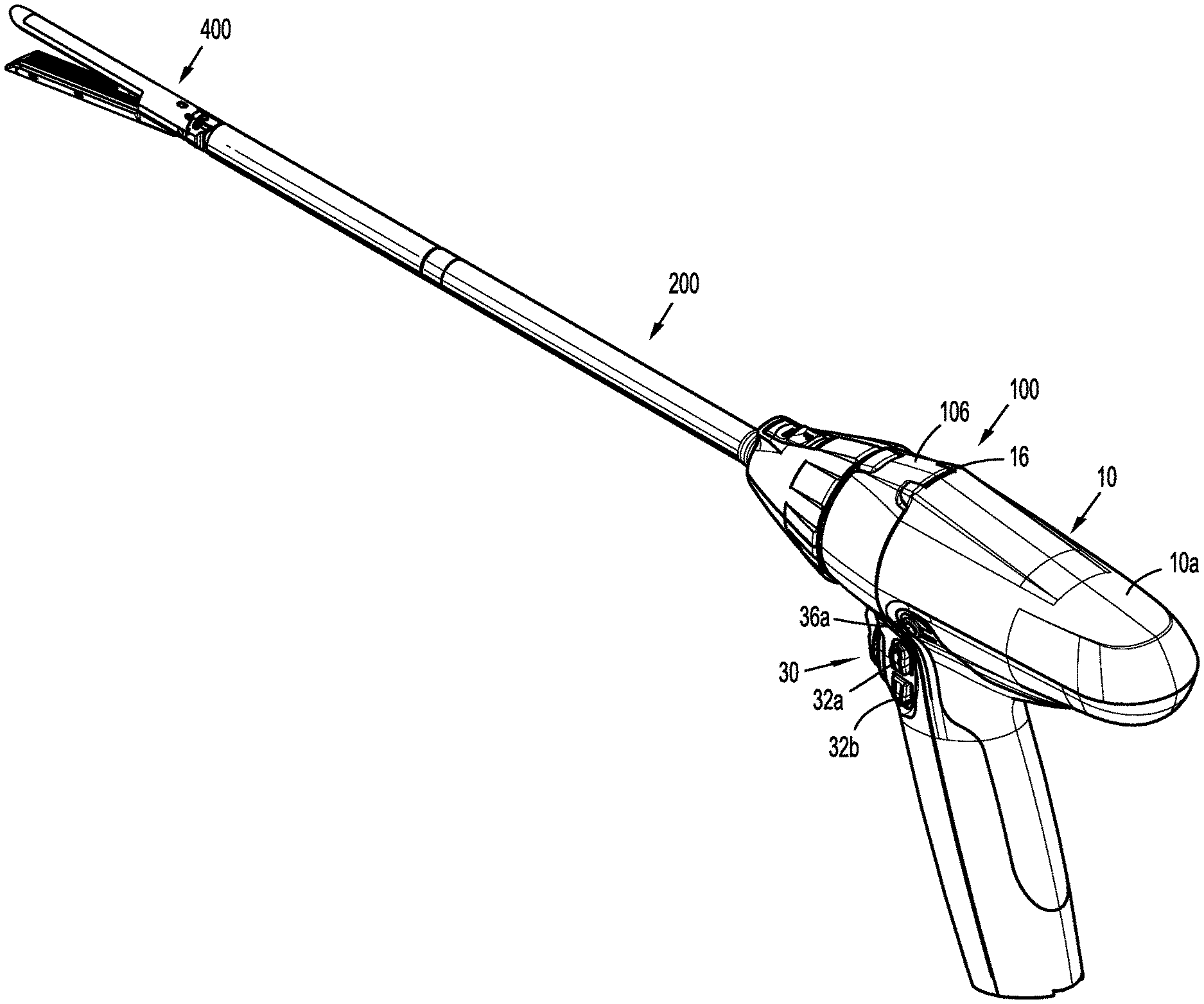
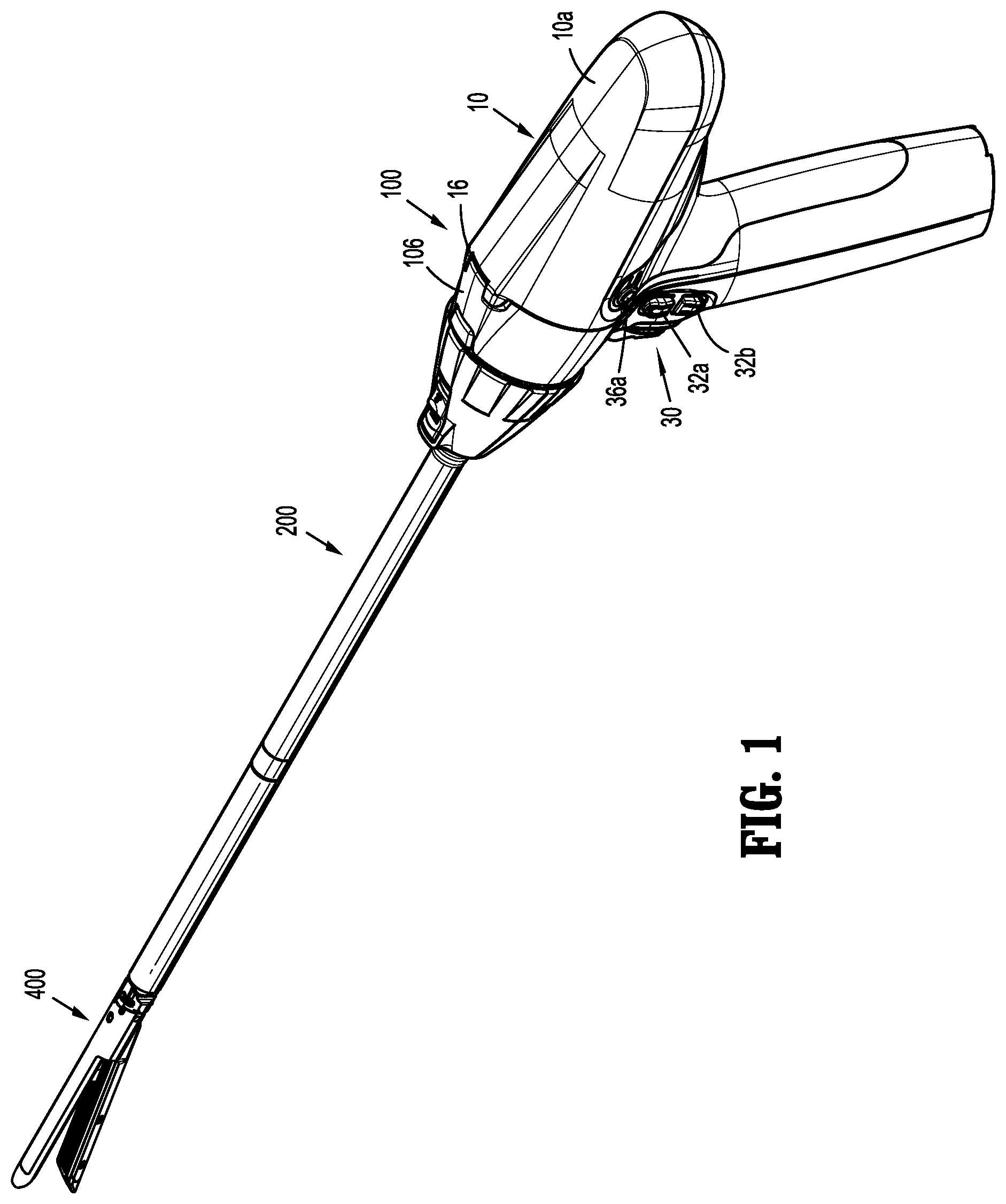
FIG. 1 is a perspective view of a handheld surgical device and adapter assembly, in accordance with an embodiment of the present disclosure, illustrating a connection thereof with an end effector;
FIG. 2 is a perspective view of the handheld surgical device of FIG. 1;
FIG. 3 is a front perspective view, with parts separated, of the handheld surgical device of FIGS. 1 and 2;
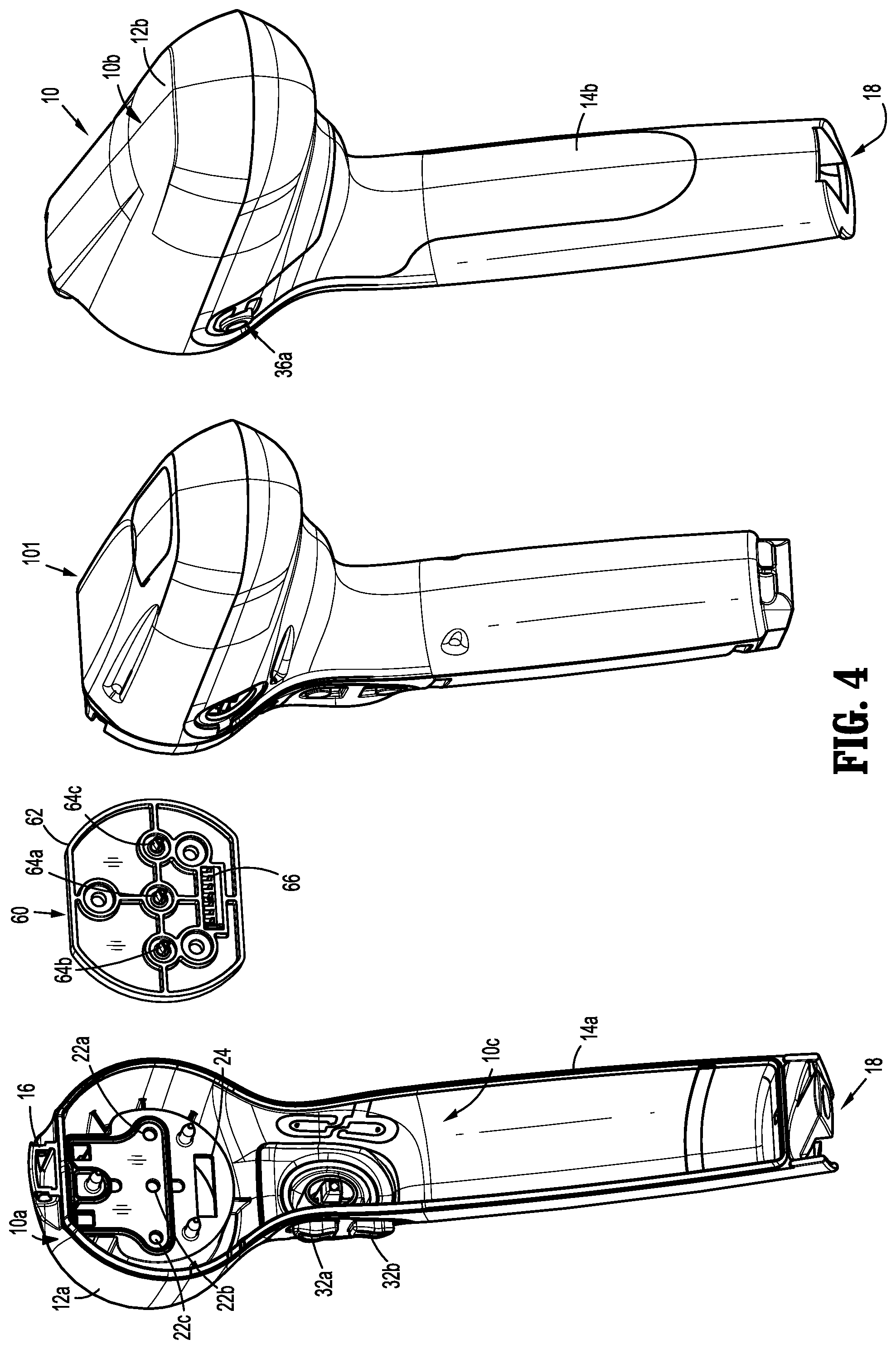
FIG. 4 is a rear perspective view, with parts separated, of the handheld surgical device of FIGS. 1 and 2;
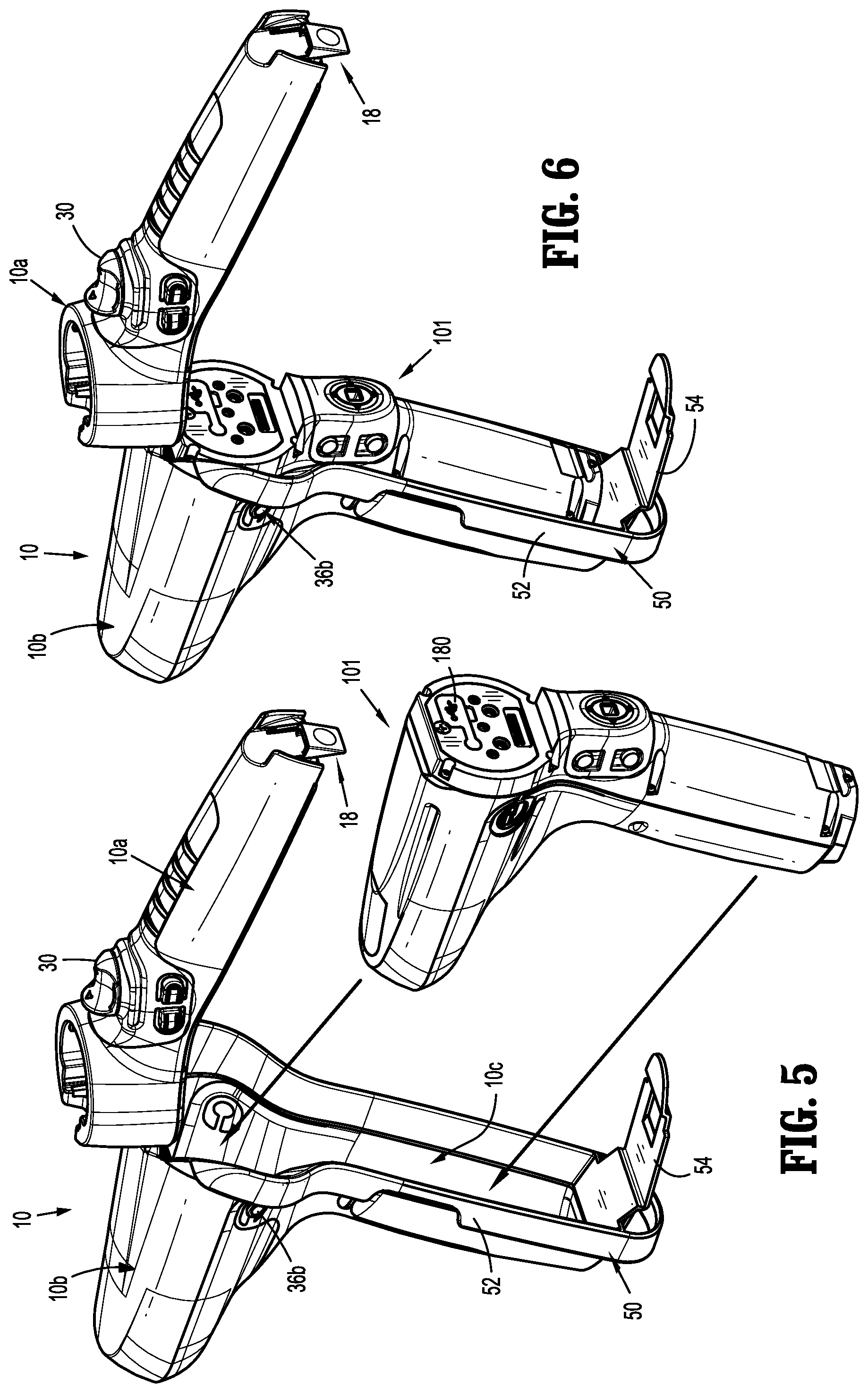
FIG. 5 is a perspective view illustrating insertion of a power-pack into an outer shell housing of the handheld surgical device;
FIG. 6 is a perspective view illustrating the power-pack nested into the outer shell housing of the handheld surgical device;
FIG. 7 is a side elevational view of the outer shell housing of the handheld surgical device;
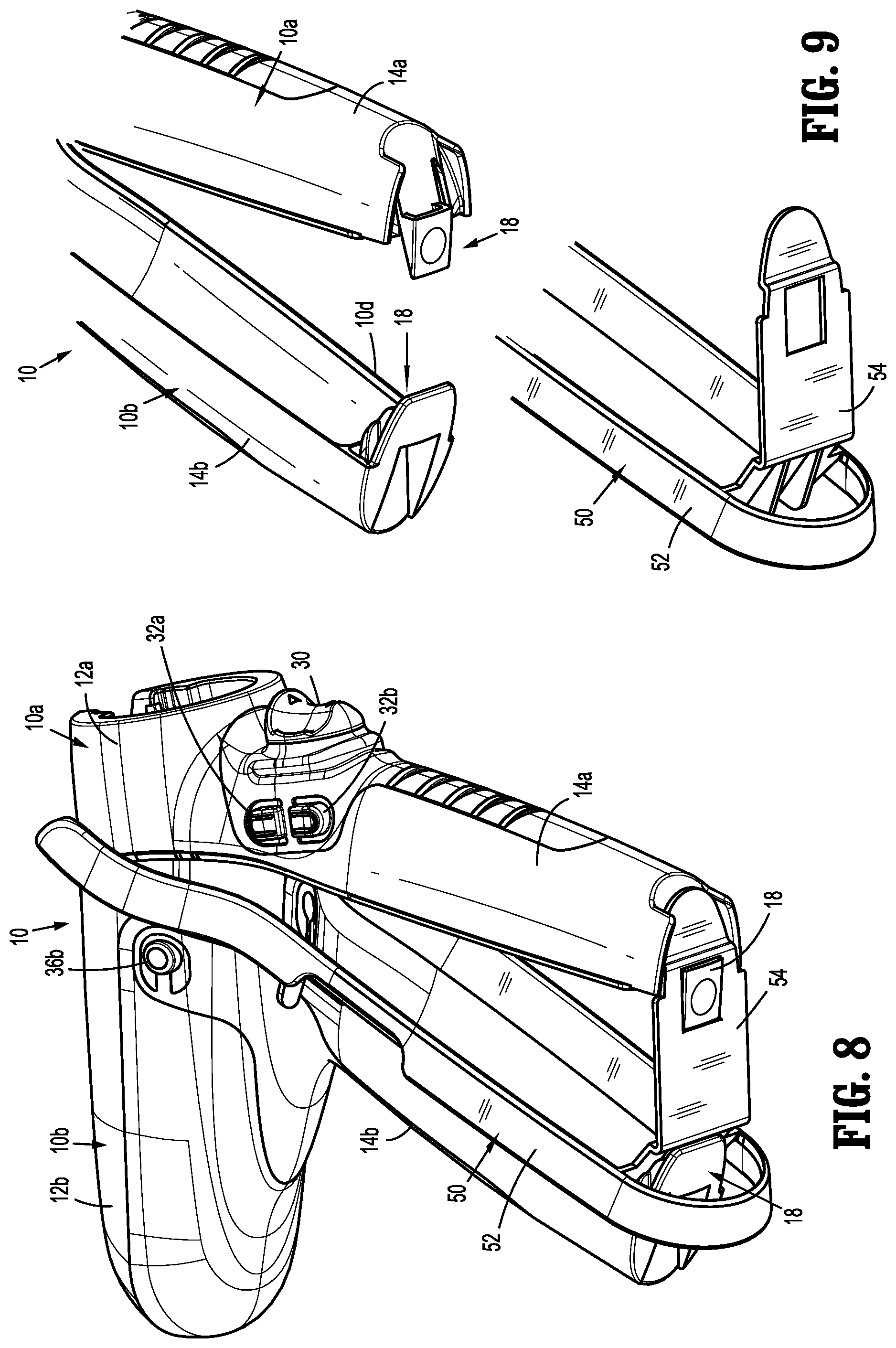
FIG. 8 is a bottom perspective view of the outer shell housing of the handheld surgical device, and an insertion guide thereof;
FIG. 9 is an enlarged, bottom perspective view of the outer shell housing of the handheld surgical device with the insertion guide separated therefrom;
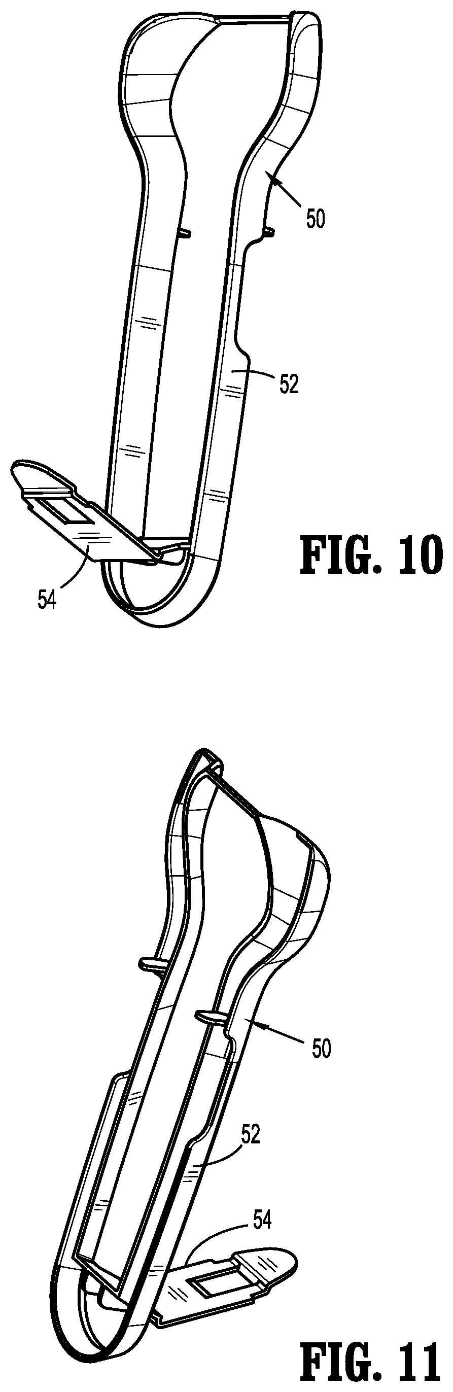
FIG. 10 is a first perspective view of the insertion guide;
FIG. 11 is a second perspective view of the insertion guide;
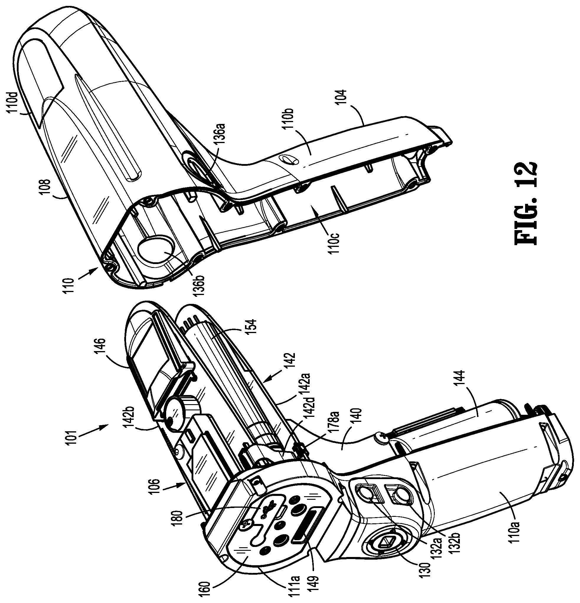
FIG. 12 is a front, perspective view of the power-pack with an inner rear housing separated therefrom;
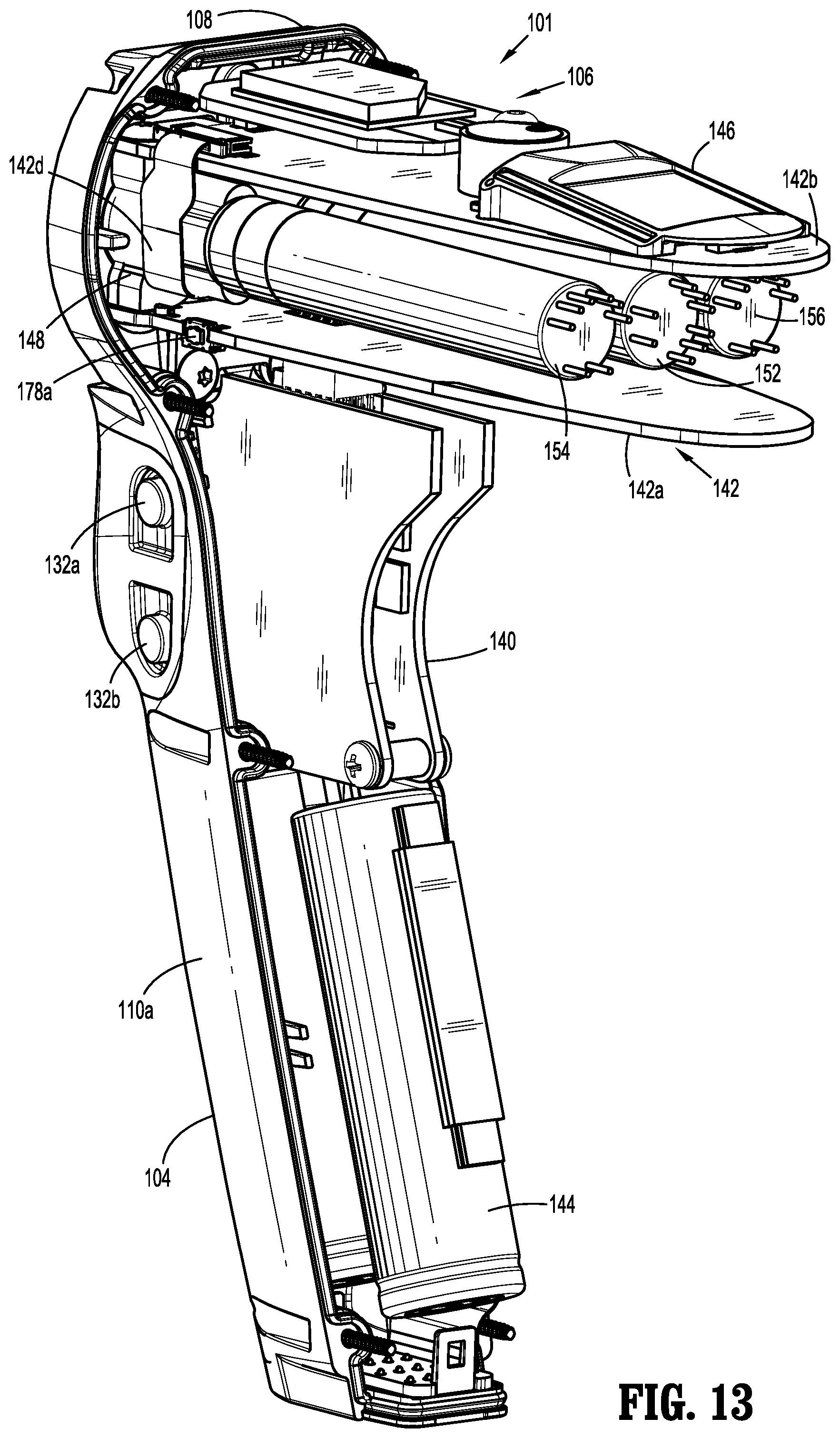
FIG. 13 is a rear, perspective view of the power-pack with the inner rear housing removed therefrom;
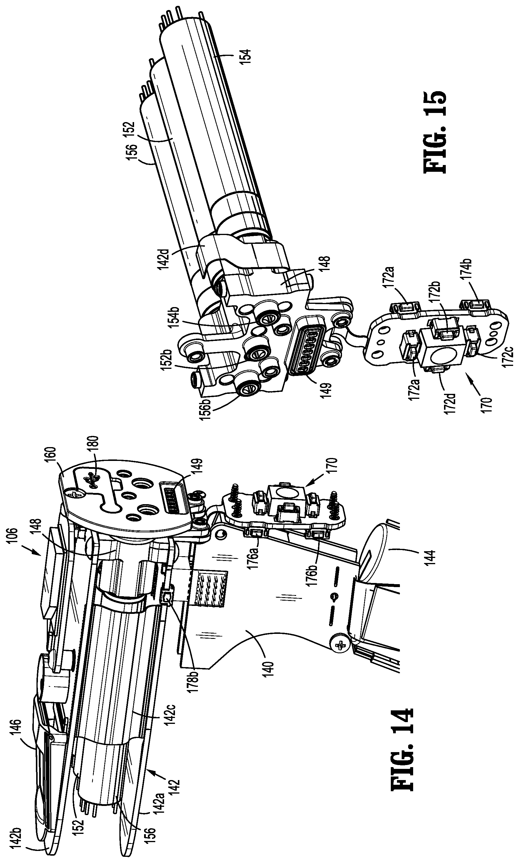
FIG. 14 is a perspective view of a power-pack core assembly of the power-pack;
FIG. 15 is a front, perspective view of a motor assembly and a control assembly of the power-pack core assembly of FIG. 14;
FIG. 16 is a rear, perspective view, with parts separated, of the motor assembly and the control assembly of FIG. 15;
FIG. 17 is a longitudinal, cross-sectional view of the handheld surgical device of FIG. 2;
FIG. 18 is an enlarged view of the indicated area of detail of FIG. 17;
FIG. 19 is a cross-sectional view of the handheld surgical device as taken through 19-19 of FIG. 17;
FIG. 20 is a front, perspective view of the adapter assembly of FIG. 1;
FIG. 21 is a rear, perspective view of the adapter assembly of FIGS. 1 and 20;
FIG. 22 is a perspective view illustrating a connection of the adapter assembly and the handheld surgical device;
FIG. 23 is a top, plan view of the adapter assembly of FIGS. 1 and 20-22;
FIG. 24 is a side, elevational view of the adapter assembly of FIGS. 1 and 20-23;
FIG. 25 is a perspective view, with parts separated, of the adapter assembly of FIGS. 1 and 20-24;
FIG. 26 is a rear, perspective view of the adapter assembly of FIGS. 1 and 20-25, with most parts thereof separated;
FIG. 27 is a perspective view of an articulation assembly of the adapter assembly of FIGS. 1 and 20-26;
FIG. 28 is an enlarged, perspective view, with parts separated, of the articulation assembly of FIG. 27;
FIG. 29 is a perspective view of the articulation assembly of FIG. 27, shown in a first orientation;
FIG. 30 is a perspective view of the articulation assembly of FIG. 27, shown in a second orientation;
FIG. 31 is a cross-sectional view of the articulation assembly of FIG. 29;
FIG. 32 is a perspective view of an electrical assembly of the adapter assembly of FIGS. 1 and 20-26;
FIG. 33 is a perspective view of the electrical assembly shown supported on a proximal inner housing assembly;
FIG. 34 is a perspective view of a slip ring cannula or sleeve of the adapter assembly of FIGS. 1 and 20-26;
FIG. 35 is a cross-sectional view as taken along section line 35-35 of FIG. 33;
FIG. 36 is a longitudinal, cross-sectional view of the adapter assembly of FIGS. 1 and 20-26;
FIG. 37 is an enlarged view of the indicated area of detail of FIG. 21;
FIG. 38 is a rear, perspective view of the inner housing assembly of the adapter assembly of FIGS. 1 and 20-26, with an outer knob housing half-section and a proximal cap removed therefrom;
FIG. 39 is a rear, perspective view of the inner housing assembly of the adapter assembly of FIGS. 1 and 20-26, with the outer knob housing, the proximal cap and a bushing plate removed therefrom;
FIG. 40 is a rear, perspective view of the inner housing assembly of the adapter assembly of FIGS. 1 and 20-26, with the outer knob housing, the proximal cap, the bushing plate and an inner housing removed therefrom;
FIG. 41 is an enlarged view of the indicated area of detail of FIG. 36;
FIG. 42 is an enlarged view of the indicated area of detail of FIG. 36, illustrating a lock button being actuated in a proximal direction;
FIG. 43 is a cross-sectional view as taken along section line 43-43 of FIG. 37;
FIG. 44 is a longitudinal, cross-sectional view of the inner and outer knob housing of the adapter assembly, illustrating actuation of the articulation assembly in a distal direction;
FIG. 45 is a cross-sectional view as taken along section line 45-45 of FIG. 44;
FIG. 46 is a cross-sectional view as taken along section line 46-46 of FIG. 44;
FIG. 47 is a cross-sectional view as taken along section line 47-47 of FIG. 44;
FIG. 48 is a cutaway view of a distal portion of the adapter assembly shown of FIGS. 1 and 20-26, without a loading unit engaged therewith;
FIG. 49 is a perspective view of an annular member of the adapter assembly of FIGS. 1 and 20-26;
FIG. 50 is a perspective view of the annular member shown in FIG. 49 electrically connected to a switch of the adapter assembly of FIGS. 1 and 20-26;
FIG. 51 is an enlarged view of the distal portion of the adapter assembly of FIGS. 1 and 20-26, including the annular member and the switch assembled therein;
FIG. 52 is another cutaway view of the distal portion of the adapter assembly of FIGS. 1 and 20-26, without a loading unit engaged therewith;
FIG. 53 is a perspective view of the loading unit of FIG. 1;
FIG. 54 is a perspective view, with parts separated, of the loading unit of FIGS. 1 and 53;
FIGS. 55 and 56 are alternate perspective views of an inner housing of the loading unit shown in FIGS. 1 and 53-54;
FIGS. 57 and 58 are alternate cutaway views of the loading unit shown in FIGS. 1 and 53-54, with the inner and outer housings assembled;
FIGS. 59 and 60 are alternate cutaway views of an outer housing of the loading unit shown in FIGS. 1 and 53-54;
FIGS. 61 and 62 are alternate cutaway views of the distal portion of the adapter assembly of FIGS. 1 and 20-26 engaged with the loading unit, illustrating the annular member in a first orientation and a sensor link in a non-locking configuration;
FIGS. 63 and 64 are alternate cutaway views of the distal portion of the adapter assembly of FIGS. 1 and 20-26 engaged with the loading unit, illustrating the annular member in a second orientation and the sensor link in a locking configuration;
FIG. 65 is an enlarged cutaway view of the distal portion of the adapter assembly of FIGS. 1 and 20-26;
FIG. 66 is a cutaway view of the loading unit of FIGS. 1 and 53-54 inserted into the annular member shown in FIG. 49;
FIG. 67 is a cross-sectional view of the loading unit of FIGS. 1 and 53-54, taken along line 67-67 of FIG. 66; and
FIG. 68 is a cross-sectional view of the loading unit of FIGS. 1 and 53-54, taken along line 68-68 of FIG. 66.
DETAILED DESCRIPTION OF EMBODIMENTS
Embodiments of the presently disclosed surgical devices, and adapter assemblies for surgical devices and/or handle assemblies are described in detail with reference to the drawings, in which like reference numerals designate identical or corresponding elements in each of the several views. As used herein the term "distal" refers to that portion of the adapter assembly or surgical device, or component thereof, farther from the user, while the term "proximal" refers to that portion of the adapter assembly or surgical device, or component thereof, closer to the user.
A surgical device, in accordance with an embodiment of the present disclosure, is generally designated as 100, and is in the form of a powered hand held electromechanical instrument configured for selective attachment thereto of a plurality of different end effectors that are each configured for actuation and manipulation by the powered hand held electromechanical surgical instrument.
As illustrated in FIG. 1, surgical device is configured for selective connection with an adapter 200, and, in turn, adapter 200 is configured for selective connection with end effectors or single use loading units ("SULU's") 400.
As illustrated in FIGS. 1-11, surgical device 100 includes a power-pack 101, and an outer shell housing 10 configured to selectively receive and substantially encase power-pack 101. Outer shell housing 10 includes a distal half-section 10a and a proximal half-section 10b pivotably connected to distal half-section 10a by a hinge 16 located along an upper edge of distal half-section 10a and proximal half-section 10b. When joined, distal and proximal half-sections 10a, 10b define a shell cavity 10c therein in which power-pack 101 is selectively situated.
Distal and proximal half-sections 10a, 10b are divided along a plane that traverses a longitudinal axis "X" of adapter 200.
Each of distal and proximal half-sections 10a, 10b includes a respective upper shell portion 12a, 12b, and a respective lower shell portion 14a, 14b. Lower shell portions 12a, 12b define a snap closure feature 18 for selectively securing lower shell portions 12a, 12b to one another and for maintaining shell housing 10 in a closed condition.
Distal half-section 10a of shell housing 10 defines a connecting portion 20 configured to accept a corresponding drive coupling assembly 210 of adapter 200. Specifically, distal half-section 10a of shell housing 10 has a recess 20 that receives a portion of drive coupling assembly 210 of adapter 200 when adapter 200 is mated to surgical device 100.
Connecting portion 20 of distal half-section 10a defines a pair of axially extending guide rails 20a, 20b projecting radially inward from inner side surfaces thereof. Guide rails 20a, 20b assist in rotationally orienting adapter 200 relative to surgical device 100 when adapter 200 is mated to surgical device 100.
Connecting portion 20 of distal half-section 10a defines three apertures 22a, 22b, 22c formed in a distally facing surface thereof and which are arranged in a common plane or line with one another. Connecting portion 20 of distal half-section 10a also defines an elongate slot 24 (to contain connector 66, see FIG. 3) also formed in the distally facing surface thereof.
Connecting portion 20 of distal half-section 10a further defines a female connecting feature 26 (see FIG. 2) formed in a surface thereof. Female connecting feature 26 selectively engages with a male connecting feature of adapter 200, as will be described in greater detail below.
Distal half-section 10a of shell housing 10 supports a distal facing toggle control button 30. Toggle control button 30 is capable of being actuated in a left, right, up and down direction upon application of a corresponding force thereto or a depressive force thereto.
Distal half-section 10a of shell housing 10 supports a right-side pair of control buttons 32a, 32b; and a left-side pair of control button 34a, 34b. Right-side control buttons 32a, 32b and left-side control buttons 34a, 34b are capable of being actuated upon application of a corresponding force thereto or a depressive force thereto.
Proximal half-section 10b of shell housing 10 supports a right-side control button 36a and a left-side control button 36b. Right-side control button 36a and left-side control button 36b are capable of being actuated upon application of a corresponding force thereto or a depressive force thereto.
Distal half-section 10a and proximal half-section 10b of shell housing 10 are fabricated from a polycarbonate or similar polymer, and are clear or transparent or may be overmolded.
With reference to FIGS. 5-11, surgical device 100 includes an insertion guide 50 that is configured and shaped to seat on and entirely surround a distal facing edge 10d (FIGS. 3 and 9) of proximal half-section 10b. Insertion guide 50 includes a body portion 52 having a substantially U-shaped transverse cross-sectional profile, and a stand-off 54 extending from a bottom of body portion 52. Stand-off 54 is configured to engage snap closure feature 18 of each of lower shell portions 12a, 12b of respective distal and proximal half-sections 10a, 10b of shell housing 10.
In use, when body portion 52 of insertion guide 50 is seated on distal facing edge 10d of proximal half-section 10b, snap closure feature 18 of lower shell portion 12a of distal half-section 10a engages a first end of stand-off 54, and snap closure feature 18 of lower shell portion 12b of proximal half-section 10b engages a first end of stand-off 54.
With reference to FIGS. 2-4, shell housing 10 includes a sterile barrier plate assembly 60 selectively supported in distal half-section 10a. Specifically, sterile barrier plate assembly 60 is disposed behind connecting portion 20 of distal half-section 10a and within shell cavity 10c of shell housing 10. Plate assembly 60 includes a plate 62 rotatably supporting three coupling shafts 64a, 64b, 64c. Each coupling shaft 64a, 64b, 64c extends from opposed sides of plate 62 and has a tri-lobe transverse cross-sectional profile. Each coupling shaft 64a, 64b, 64c extends through a respective aperture 22a, 22b, 22c of connecting portion 20 of distal half-section 10a when sterile barrier plate assembly 60 is disposed within shell cavity 10c of shell housing 10.
Plate assembly 60 further includes an electrical pass-through connector 66 supported on plate 62. Pass-through connector 66 extends from opposed sides of plate 62. Each coupling shaft 64a, 64b, 64c extends through aperture 24 of connecting portion 20 of distal half-section 10a when sterile barrier plate assembly 60 is disposed within shell cavity 10c of shell housing 10. Pass-through connector 66 defines a plurality of contact paths each including an electrical conduit for extending an electrical connection across plate 62.
When plate assembly 60 is disposed within shell cavity 10c of shell housing 10, distal ends of coupling shaft 64a, 64b, 64c and a distal end of pass-through connector 66 are disposed or situated within connecting portion 20 of distal half-section 10a of shell housing 10, and electrically and/or mechanically engage respective corresponding features of adapter 200, as will be described in greater detail below.
In operation, with a new and/or sterile shell housing 10 in an open configuration (i.e., distal half-section 10a separated from proximal half-section 10b, about hinge 16), and with insertion guide 50 in place against the distal edge of proximal half-section 10b of shell housing 10, power-pack 101 is inserted into shell cavity 10c of shell housing 10. With power-pack 101 inserted into shell cavity 10c of shell housing 10, insertion guide 50 is removed from proximal half-section 10b and distal half-section 10a is pivoted, about hinge 16, to a closed configuration for shell housing 10. In the closed configuration, snap closure feature 18 of lower shell portion 12a of distal half-section 10a engages snap closure feature 18 of lower shell portion 12b of proximal half-section 10b.
In operation, following a surgical procedure, snap closure feature 18 of lower shell portion 12a of distal half-section 10a is disengaged from snap closure feature 18 of lower shell portion 12b of proximal half-section 10b, and distal half-section 10a is pivoted, about hinge 16, away from proximal half-section 10b to open shell housing 10. With shell housing 10 open, power-pack 101 is removed from shell cavity 10c of shell housing 10 (specifically from proximal half-section 10b of shell housing 10), and shell housing 10 is discarded.
Power-pack 101 is then disinfected and cleaned. Power-pack 101 is not to be submerged or sterilized.
Referring to FIGS. 3-6 and FIGS. 12-19, surgical device 100 includes a power-pack 101. Power-pack 101 includes an inner handle housing 110 having a lower housing portion 104 and an upper housing portion 108 extending from and/or supported on lower housing portion 104. Lower housing portion 104 and upper housing portion 108 are separated into a distal half-section 110a and a proximal half-section 110b connectable to distal half-section 110a by a plurality of fasteners. When joined, distal and proximal half-sections 110a, 110b define an inner handle housing 110 having an inner housing cavity 110c therein in which a power-pack core assembly 106 is situated.
Power-pack core assembly 106 is configured to control the various operations of surgical device 100, as will be set forth in additional detail below.
Distal half-section 110a of inner handle housing 110 defines a distal opening 111a therein which is configured and adapted to support a control plate 160 of power-pack core assembly 106. Control plate 160 of power-pack 101 abuts against a rear surface of plate 62 of sterile barrier plate assembly 60 of shell housing 10 when power-pack 101 is disposed within shell housing 10.
With reference to FIG. 12, distal half-section 110a of inner handle housing 110 supports a distal toggle control interface 130 that is in operative registration with distal toggle control button 30 of shell housing 10. In use, when power-pack 101 is disposed within shell housing 10, actuation of toggle control button 30 exerts a force on toggle control interface 130.
Distal half-section 110a of inner handle housing 110 also supports a right-side pair of control interfaces 132a, 132b, and a left-side pair of control interfaces 134a, 134b. In use, when power-pack 101 is disposed within shell housing 10, actuation of one of the right-side pair of control buttons 32a, 32b or the left-side pair of control button 34a, 34b of distal half-section 10a of shell housing 10 exerts a force on a respective one of the right-side pair of control interfaces 132a, 132b or the left-side pair of control interfaces 134a, 134b of distal half-section 110a of inner handle housing 110.
In use, right-side pair of control interfaces 132a, 132b or the left-side pair of control interfaces 134a, 134b of distal half-section 110a of inner handle housing 110 will be deactived or fail to function unless shell housing 10 has been validated.
Proximal half-section 110b of inner handle housing 110 defines a right-side control aperture 136a and a left-side control aperture 136b. In use, when power-pack 101 is disposed within shell housing 10, actuation of one of the right-side control button 36a or the left-side control button 36b of proximal half-section 10b of shell housing 10 extends the right-side control button 36a or the left-side control button 36b into and across the right-side control aperture 136a or the left-side control aperture 136b of the proximal half-section 110b of inner handle housing 110.
With reference to FIGS. 12-19, inner handle housing 110 provides a housing in which power-pack core assembly 106 is situated. Power-pack core assembly 106 includes a battery circuit 140, a controller circuit board 142 and a rechargeable battery 144 configured to supply power to any of the electrical components of surgical device 100. Controller circuit board 142 includes a motor controller circuit board 142a, a main controller circuit board 142b, and a first ribbon cable 142c interconnecting motor controller circuit board 142a and main controller circuit board 142b.
Power-pack core assembly 106 further includes a display screen 146 supported on main controller circuit board 142b. Display screen 146 is visible through a clear or transparent window 110d (see FIGS. 12 and 17) provided in proximal half-section 110b of inner handle housing 110. It is contemplated that at least a portion of inner handle housing 110 may be fabricated from a transparent rigid plastic or the like. It is further contemplated that shell housing 10 may either include a window formed therein (in visual registration with display screen 146 and with window 110d of proximal half-section 110b of inner handle housing 110, and/or shell housing 10 may be fabricated from a transparent rigid plastic or the like.
Power-pack core assembly 106 further includes a first motor 152, a second motor 154, and a third motor 156 each electrically connected to controller circuit board 142 and battery 144. Motors 152, 154, 156 are disposed between motor controller circuit board 142a and main controller circuit board 142b. Each motor 152, 154, 156 includes a respective motor shaft 152a, 154a, 156a extending therefrom. Each motor shaft 152a, 154a, 156a has a tri-lobe transverse cross-sectional profile for transmitting rotative forces or torque.
Each motor 152, 154, 156 is controlled by a respective motor controller. The motor controllers are disposed on motor controller circuit board 142a and are, for example, A3930/31K motor drivers from Allegro Microsystems, Inc. The A3930/31K motor drivers are designed to control a 3-phase brushless DC (BLDC) motor with N-channel external power MOSFETs, such as the motors 152, 154, 156. Each of the motor controllers is coupled to a main controller disposed on the main controller circuit board 142b. The main controller is also coupled to memory, which is also disposed on the main controller circuit board 142b. The main controller is, for example, an ARM Cortex M4 processor from Freescale Semiconductor, Inc, which includes 1024 kilobytes of internal flash memory. The main controller communicates with the motor controllers through an FPGA, which provides control logic signals (e.g., coast, brake, etc.). The control logic of the motor controllers then outputs corresponding energization signals to their respective motors 152, 154, 156 using fixed-frequency pulse width modulation (PWM).
Each motor 152, 154, 156 is supported on a motor bracket 148 such that motor shaft 152a, 154a, 156a are rotatably disposed within respective apertures of motor bracket 148. As illustrated in FIGS. 16 and 19, motor bracket 148 rotatably supports three rotatable drive connector sleeves 152b, 154b, 156b that are keyed to respective motor shafts 152a, 154a, 156a of motors 152, 154, 156. Drive connector sleeves 152b, 154b, 156b non-rotatably receive proximal ends of respective coupling shaft 64a, 64b, 64c of plate assembly 60 of shell housing 10, when power-pack 101 is disposed within shell housing 10. Drive connector sleeves 152b, 154b, 156b are each spring biased away from respective motors 152, 154, 156.
Rotation of motor shafts 152a, 154a, 156a by respective motors 152, 154, 156 function to drive shafts and/or gear components of adapter 200 in order to perform the various operations of surgical device 100. In particular, motors 152, 154, 156 of power-pack core assembly 106 are configured to drive shafts and/or gear components of adapter 200 in order to selectively move tool assembly 404 of SULU 400 relative to proximal body portion 402 of SULU 400, to rotate SULU 400 about a longitudinal axis "X", to move cartridge assembly 408 relative to anvil assembly 406 of SULU 400, and/or to fire staples from within cartridge assembly 408 of SULU 400.
Motor bracket 148 also supports an electrical receptacle 149. Electrical receptacle 149 is in electrical connection with main controller circuit board 142b by a second ribbon cable 142d. Electrical receptacle 149 defines a plurality of electrical slots for receiving respective electrical contacts or blades extending from pass-through connector 66 of plate assembly 60 of shell housing 10.
In use, when adapter 200 is mated to surgical device 100, each of coupling shaft 64a, 64b, 64c of plate assembly 60 of shell housing 10 of surgical device 100 couples with a corresponding rotatable connector sleeves 218, 220, 222 of adapter 200 (see FIG. 22). In this regard, the interface between corresponding first coupling shaft 64a and first connector sleeve 218, the interface between corresponding second coupling shaft 64b and second connector sleeve 220, and the interface between corresponding third coupling shaft 64c and third connector sleeve 222 are keyed such that rotation of each of coupling shafts 64a, 64b, 64c of surgical device 100 causes a corresponding rotation of the corresponding connector sleeve 218, 220, 222 of adapter 200.
The mating of coupling shafts 64a, 64b, 64c of surgical device 100 with connector sleeves 218, 220, 222 of adapter 200 allows rotational forces to be independently transmitted via each of the three respective connector interfaces. The coupling shafts 64a, 64b, 64c of surgical device 100 are configured to be independently rotated by respective motors 152, 154, 156.
Since each of coupling shafts 64a, 64b, 64c of surgical device 100 has a keyed and/or substantially non-rotatable interface with respective connector sleeves 218, 220, 222 of adapter 200, when adapter 200 is coupled to surgical device 100, rotational force(s) are selectively transferred from motors 152, 154, 156 of surgical device 100 to adapter 200.
The selective rotation of coupling shaft(s) 64a, 64b, 64c of surgical device 100 allows surgical device 100 to selectively actuate different functions of SULU 400. As will be discussed in greater detail below, selective and independent rotation of first coupling shaft 64a of surgical device 100 corresponds to the selective and independent opening and closing of tool assembly 404 of SULU 400, and driving of a stapling/cutting component of tool assembly 404 of SULU 400. Also, the selective and independent rotation of second coupling shaft 64b of surgical device 100 corresponds to the selective and independent articulation of tool assembly 404 of SULU 400 transverse to longitudinal axis "X" (see FIG. 21). Additionally, the selective and independent rotation of third coupling shaft 64c of surgical device 100 corresponds to the selective and independent rotation of SULU 400 about longitudinal axis "X" (see FIG. 21) relative to surgical device 100.
With reference to FIGS. 12-19, power-pack core assembly 106 further includes a switch assembly 170 supported within distal half-section 110a of inner handle housing 110, at a location beneath and in registration with toggle control interface 130, the right-side pair of control interfaces 132a, 132b, and the left-side pair of control interfaces 134a, 134b. Switch assembly 170 includes a first set of four push-button switches 172a-172d arranged around stem 30a of toggle control button 30 of outer shell housing 10 when power-pack 101 is disposed within outer shell housing 10. Switch assembly 170 also includes a second pair of push-button switches 174a, 174b disposed beneath right-side pair of control interfaces 132a, 132b of distal half-section 110a of inner handle housing 110 when power-pack 101 is disposed within outer shell housing 10. Switch assembly 170 further includes a third pair of push-button switches 176a, 176b disposed beneath left-side pair of control interfaces 134a, 134b of distal half-section 110a of inner handle housing 110 when power-pack 101 is disposed within outer shell housing 10.
Power-pack core assembly 106 includes a single right-side push-button switch 178a disposed beneath right-side control aperture 136a of proximal half-section 110b of inner handle housing 110, and a single left-side push-button switch 178b disposed beneath left-side control aperture 136b of proximal half-section 110b of inner handle housing 110. Push-button switches 178a, 178b are supported on controller circuit board 142. Push-button switches 178a, 178b are disposed beneath right-side control button 36a and left-side control button 36b of proximal half-section 10b of shell housing 10 when power-pack 101 is disposed within outer shell housing 10.
The actuation of push button switch 172c, corresponding to a downward actuation of toggle control button 30, causes controller circuit board 142 to provide appropriate signals to motor 152 to close a tool assembly 404 of SULU 400 and/or to fire staples from within cartridge assembly 408 of SULU 400.
The actuation of push button switch 172a, corresponding to an upward actuation of toggle control button 30, causes controller circuit board 142 to provide appropriate signals to motor 152 to retract a staple sled and open tool assembly 404 of SULU 400.
The actuation of push button 172d, corresponding to an actuation of toggle control button 30 to the right, causes controller circuit board 142 to provide appropriate signals to motor 152 to articulate tool assembly 404 to the right relative to body portion 402 of SULU 400. Similarly, the actuation of push button 172b, corresponding to an actuation of toggle control button 30 to the left, causes controller circuit board 142 to provide appropriate signals to motor 152 to articulate tool assembly 404 to the left relative to body portion 402 of SULU 400.
The actuation of switches 174a, 174b (by right-hand thumb of user) or switches 176a, 176b (by left-hand thumb of user), corresponding to respective actuation of right-side pair of control buttons 32a, 32b or left-side pair of control button 34a, 34b, causes controller circuit board 142 to provide appropriate signals to motor 154 to rotate SULU 400 relative to surgical device 100. Specifically, actuation of control button 32a or 34a causes SULU 400 to rotate relative to surgical device 100 in a first direction, while actuation of control button 32b or 34b causes SULU 400 to rotate relative to surgical device 100 in an opposite, e.g., second, direction.
In use, tool assembly 404 of SULU 400 is actuated between opened and closed conditions as needed and/or desired. In order to fire SULU 400, to expel fasteners therefrom, when tool assembly 404 of SULU 400 is in a closed condition, safety switch 178a or 178b is depressed thereby instructing surgical device 100 that SULU 400 is ready to expel fasteners therefrom.
With reference to FIGS. 12 and 14, power-pack core assembly 106 of surgical device 100 includes a USB connector 180 supported on main controller circuit board 142b of controller circuit board 142. USB connector 180 is accessible through control plate 160 of power-pack core assembly 106. When power-pack 101 is disposed within outer shell housing 10, USB connector 180 is covered by plate 62 of sterile barrier plate assembly 60 of shell housing 10.
As illustrated in FIG. 1 and FIGS. 20-52, surgical device 100 is configured for selective connection with adapter 200, and, in turn, adapter 200 is configured for selective connection with SULU 400.
Adapter 200 is configured to convert a rotation of either of drive connector sleeve 152b or 156b of surgical device 100 into axial translation useful for operating a drive assembly 460 and an articulation link 466 of SULU 400, as illustrated in FIG. 54, and as will be discussed in greater detail below.
Adapter 200 includes a first drive transmitting/converting assembly for interconnecting first drive connector sleeve 152a of surgical device 100 and a first axially translatable drive member of SULU 400, wherein the first drive transmitting/converting assembly converts and transmits a rotation of first drive connector sleeve 152a of surgical device 100 to an axial translation of the first axially translatable drive assembly 460 of SULU 400 for firing.
Adapter 200 includes a second drive transmitting/converting assembly for interconnecting third drive connector sleeve 156b of surgical device 100 and a second axially translatable drive member of SULU 400, wherein the second drive transmitting/converting assembly converts and transmits a rotation of third drive connector sleeve 156b of surgical device 100 to an axial translation of articulation link 466 of SULU 400 for articulation.
Turning now to FIGS. 21-47, adapter 200 includes an outer knob housing 202 and an outer tube 206 extending from a distal end of knob housing 202. Knob housing 202 and outer tube 206 are configured and dimensioned to house the components of adapter assembly 200. Outer tube 206 is dimensioned for endoscopic insertion, in particular, that outer tube is passable through a typical trocar port, cannula or the like. Knob housing 202 is dimensioned to not enter the trocar port, cannula of the like. Knob housing 202 is configured and adapted to connect to connecting portion 108 of handle housing 102 of surgical device 100.
Adapter 200 is configured to convert a rotation of either of first or second coupling shafts 64a, 64b of surgical device 100 into axial translation useful for operating a drive assembly 460 and an articulation link 466 of SULU 400, as illustrated in FIG. 54 and as will be described in greater detail below. As illustrated in FIGS. 26 and 38-47, adapter 200 includes a proximal inner housing assembly 204 rotatably supporting a first rotatable proximal drive shaft 212, a second rotatable proximal drive shaft 214, and a third rotatable proximal drive shaft 216 therein. Each proximal drive shaft 212, 214, 216 functions as a rotation receiving member to receive rotational forces from respective coupling shafts 64a, 64b and 64c of surgical device 100, as described in greater detail below.
As described briefly above, drive coupling assembly 210 of adapter 200 is also configured to rotatably support first, second and third connector sleeves 218, 222 and 220, respectively, arranged in a common plane or line with one another. Each of connector sleeves 218, 222, 220 is configured to mate with respective first, second and third coupling shafts 64a, 64c and 64b of surgical device 100, as described above. Each of connector sleeves 218, 222, 220 is further configured to mate with a proximal end of respective first, second and third proximal drive shafts 212, 214, 216 of adapter 200.
Drive coupling assembly 210 of adapter 200 also includes, as illustrated in FIGS. 26, 38 and 41-44, a first, a second and a third biasing member 224, 226 and 228 disposed distally of respective first, second and third connector sleeves 218, 220, 222. Each of biasing members 224, 226 and 228 is disposed about respective first, second and third rotatable proximal drive shaft 212, 214 and 216. Biasing members 224, 226 and 228 act on respective connector sleeves 218, 222 and 220 to help maintain connector sleeves 218, 222 and 220 engaged with the distal end of respective coupling shafts 64a, 64c and 64b of surgical device 100 when adapter 200 is connected to surgical device 100.
In particular, first, second and third biasing members 224, 226 and 228 function to bias respective connector sleeves 218, 222 and 220 in a proximal direction. In this manner, during connection of surgical device 100 when adapter 200 to surgical device 100, if first, second and or third connector sleeves 218, 222 and/or 220 is/are misaligned with coupling shafts 64a, 64c and 64b of surgical device 100, first, second and/or third biasing member(s) 224, 226 and/or 228 are compressed. Thus, when surgical device 100 is operated, coupling shafts 64a, 64c and 64b of surgical device 100 will rotate and first, second and/or third biasing member(s) 224, 226 and/or 228 will cause respective first, second and/or third connector sleeve(s) 218, 222 and/or 220 to slide back proximally, effectively connecting coupling shafts 64a, 64c and 64b of surgical device 100 to first, second and/or third proximal drive shaft(s) 212, 214 and 216 of drive coupling assembly 210.
Adapter 200 includes a plurality of force/rotation transmitting/converting assemblies, each disposed within inner housing assembly 204 and outer tube 206. Each force/rotation transmitting/converting assembly is configured and adapted to transmit/convert a speed/force of rotation (e.g., increase or decrease) of first, second and third rotatable coupling shafts 64a, 64c and 64b of surgical device 100 before transmission of such rotational speed/force to SULU 400.
Specifically, as illustrated in FIG. 26, adapter 200 includes a first, a second and a third force/rotation transmitting/converting assembly 240, 250, 260, respectively, disposed within inner housing assembly 204 and outer tube 206. Each force/rotation transmitting/converting assembly 240, 250, 260 is configured and adapted to transmit or convert a rotation of a first, second and third coupling shafts 64a, 64c and 64b of surgical device 100 into axial translation of articulation bar 258 of adapter 200, to effectuate articulation of SULU 400; a rotation of a ring gear 266 of adapter 200, to effectuate rotation of adapter 200; or axial translation of a distal drive member 248 of adapter 200 to effectuate closing, opening and firing of SULU 400.
As shown in FIGS. 26 and 41-45, first force/rotation transmitting/converting assembly 240 includes first rotatable proximal drive shaft 212, which, as described above, is rotatably supported within inner housing assembly 204. First rotatable proximal drive shaft 212 includes a non-circular or shaped proximal end portion configured for connection with first connector 218 which is connected to respective first coupling shaft 64a of surgical device 100. First rotatable proximal drive shaft 212 includes a distal end portion 212b having a threaded outer profile or surface.
First force/rotation transmitting/converting assembly 240 further includes a drive coupling nut 244 rotatably coupled to threaded distal end portion 212b of first rotatable proximal drive shaft 212, and which is slidably disposed within outer tube 206. Drive coupling nut 244 is slidably keyed within proximal core tube portion of outer tube 206 so as to be prevented from rotation as first rotatable proximal drive shaft 212 is rotated. In this manner, as first rotatable proximal drive shaft 212 is rotated, drive coupling nut 244 is translated along threaded distal end portion 212b of first rotatable proximal drive shaft 212 and, in turn, through and/or along outer tube 206.
First force/rotation transmitting/converting assembly 240 further includes a distal drive member 248 that is mechanically engaged with drive coupling nut 244, such that axial movement of drive coupling nut 244 results in a corresponding amount of axial movement of distal drive member 248. The distal end portion of distal drive member 248 supports a connection member 247 configured and dimensioned for selective engagement with a drive member 474 of drive assembly 460 of SULU 400 (FIG. 54). Drive coupling nut 244 and/or distal drive member 248 function as a force transmitting member to components of SULU 400, as described in greater detail below.
In operation, as first rotatable proximal drive shaft 212 is rotated, due to a rotation of first connector sleeve 218, as a result of the rotation of first coupling shaft 64a of surgical device 100, drive coupling nut 244 is caused to be translated axially along first distal drive shaft 242. As drive coupling nut 244 is caused to be translated axially along first distal drive shaft 242, distal drive member 248 is caused to be translated axially relative to outer tube 206. As distal drive member 248 is translated axially, with connection member 247 connected thereto and engaged with drive member 474 of drive assembly 460 of SULU 400 (FIG. 54), distal drive member 248 causes concomitant axial translation of drive member 474 of SULU 400 to effectuate a closure of tool assembly 404 and a firing of tool assembly 404 of SULU 400.
With reference to FIGS. 26-31, 45 and 46, second drive converter assembly 250 of adapter 200 includes second proximal drive shaft 214 rotatably supported within inner housing assembly 204. Second rotatable proximal drive shaft 214 includes a non-circular or shaped proximal end portion configured for connection with second connector or coupler 222 which is connected to respective second coupling shaft 64c of surgical device 100. Second rotatable proximal drive shaft 214 further includes a distal end portion 214b having a threaded outer profile or surface.
Distal end portion 214a of proximal drive shaft 214 is threadably engaged with an articulation bearing housing 252a of an articulation bearing assembly 252. Articulation bearing assembly 252 includes a housing 252a supporting an articulation bearing 253 having an inner race 253b that is independently rotatable relative to an outer race 253a. Articulation bearing housing 252a has a non-circular outer profile, for example tear-dropped shaped, that is slidably and non-rotatably disposed within a complementary bore 204c (FIGS. 45 and 46) of inner housing hub 204a.
Second drive converter assembly 250 of adapter 200 further includes an articulation bar 258 having a proximal portion 258a secured to inner race 253b of articulation bearing 253. A distal portion 258b of articulation bar 258 includes a slot 258c therein, which is configured to accept a flag of the articulation link 466 (FIG. 54) of SULU 400. Articulation bar 258 functions as a force transmitting member to components of SULU 400, as described in greater detail below.
With further regard to articulation bearing assembly 252, articulation bearing assembly 252 is both rotatable and longitudinally translatable. Additionally, it is envisioned that articulation bearing assembly 252 allows for free, unimpeded rotational movement of SULU 400 when its jaw members 406, 408 are in an approximated position and/or when jaw members 406, 408 are articulated.
In operation, as second proximal drive shaft 214 is rotated due to a rotation of second connector sleeve 222, as a result of the rotation of the second coupling shaft 64c of surgical device 100, articulation bearing assembly 252 is caused to be translated axially along threaded distal end portion 214b of second proximal drive shaft 214, which in turn causes articulation bar 258 to be axially translated relative to outer tube 206. As articulation bar 258 is translated axially, articulation bar 258, being coupled to articulation link 466 of SULU 400, causes concomitant axial translation of articulation link 466 of SULU 400 to effectuate an articulation of tool assembly 404. Articulation bar 258 is secured to inner race 253b of articulation bearing 253 and is thus free to rotate about the longitudinal axis X-X relative to outer race 253a of articulation bearing 253.
As illustrated in FIGS. 26, 38, 39, 43, 44 and 47, and as described, adapter 200 includes a third force/rotation transmitting/converting assembly 260 supported in inner housing assembly 204. Third force/rotation transmitting/converting assembly 260 includes a rotation ring gear 266 fixedly supported in and connected to outer knob housing 202. Ring gear 266 defines an internal array of gear teeth 266a (FIG. 26). Ring gear 266 includes a pair of diametrically opposed, radially extending protrusions 266b (FIG. 26) projecting from an outer edge thereof. Protrusions 266b are disposed within recesses defined in outer knob housing 202, such that rotation of ring gear 266 results in rotation of outer knob housing 202, and vice a versa.
Third force/rotation transmitting/converting assembly 260 further includes third rotatable proximal drive shaft 216 which, as described above, is rotatably supported within inner housing assembly 204. Third rotatable proximal drive shaft 216 includes a non-circular or shaped proximal end portion configured for connection with third connector 220 which is connected to respective third connector 122 of surgical device 100. Third rotatable proximal drive shaft 216 includes a spur gear 216a keyed to a distal end thereof. A reversing spur gear 264 inter-engages spur gear 216a of third rotatable proximal drive shaft 216 to gear teeth 266a of ring gear 266.
In operation, as third rotatable proximal drive shaft 216 is rotated, due to a rotation of third connector sleeve 220, as a result of the rotation of the third coupling shaft 64b of surgical device 100, spur gear 216a of third rotatable proximal drive shaft 216 engages reversing gear 264 causing reversing gear 264 to rotate. As reversing gear 264 rotates, ring gear 266 also rotates thereby causing outer knob housing 202 to rotate. As outer knob housing 202 is rotated, outer tube 206 is caused to be rotated about longitudinal axis "X" of adapter 200. As outer tube 206 is rotated, SULU 400, that is connected to a distal end portion of adapter 200, is also caused to be rotated about a longitudinal axis of adapter 200.
Adapter 200 further includes, as seen in FIGS. 22-25, an attachment/detachment button 272 supported thereon. Specifically, button 272 is supported on a stem 273 (FIGS. 25, 26, 41 and 42) projecting from drive coupling assembly 210 of adapter 200, and is biased by a biasing member 274, disposed within or around stem 273, to an un-actuated condition. Button 272 includes a lip or ledge 272a formed therewith that is configured to snap behind a corresponding lip or ledge 108b defined along recess 108a of connecting portion 108 of handle housing 102 of surgical device 100. While stem 273 is illustrated as having a relatively longer length to improve/increase stability of button 272 during actuation, it is envisioned that stem 273 may have a relatively shorter length than the length depicted.
In use, when adapter 200 is connected to surgical device 100, lip 272a of button 272 is disposed behind lip 108b of connecting portion 108 of handle housing 102 of surgical device 100 to secure and retain adapter 200 and surgical device 100 with one another. In order to permit disconnection of adapter 200 and surgical device 100 from one another, button 272 is depressed or actuated, against the bias of biasing member 274, to disengage lip 272a of button 272 and lip 108b of connecting portion 108 of handle housing 102 of surgical device 100.
With reference to FIGS. 23-25 and 48-52, adapter 200 further includes a lock mechanism 280 for fixing the axial position of distal drive member 248. Lock mechanism 280 includes a button 282 slidably supported on outer knob housing 202. Lock button 282 is connected to an actuation bar 284 that extends longitudinally through outer tube 206. Actuation bar 284 moves upon a movement of lock button 282.
In operation, in order to lock the position and/or orientation of distal drive member 248, a user moves lock button 282 from a distal position to a proximal position (FIGS. 25 and 41), thereby causing the lock out (not shown) to move proximally such that a distal face of the lock out moves out of contact with camming member 288, which causes camming member 288 to cam into recess 249 of distal drive member 248. In this manner, distal drive member 248 is prevented from distal and/or proximal movement. When lock button 282 is moved from the proximal position to the distal position, the distal end of actuation bar 284 moves distally into the lock out (not shown), against the bias of a biasing member (not shown), to force camming member 288 out of recess 249, thereby allowing unimpeded axial translation and radial movement of distal drive member 248.
With reference to FIGS. 32-39, adapter 200 includes an electrical assembly 290 supported on and in outer knob housing 202 and inner housing assembly 204. Electrical assembly 290 includes a plurality of electrical contact blades 292, supported on a circuit board 294, for electrical connection to pass-through connector 66 of plate assembly 60 of shell housing 10 of surgical device 100. Electrical assembly 290 serves to allow for calibration and communication information (i.e., life-cycle information, system information, force information) to the circuit board of surgical device 100 via electrical receptacle 149 of power-pack core assembly 106 of surgical device 100.
Electrical assembly 290 further includes a strain gauge 296 electrically connected to circuit board 294. Strain gauge 296 is provided with a notch 296a which is configured and adapted to receive stem 204d of hub 204a of inner housing assembly 204. Stem 204d of hub 204a functions to restrict rotational movement of strain gauge 296. As illustrated in FIGS. 32, 35 and 39, first rotatable proximal drive shaft 212 extends through strain gauge 296. Strain gauge 296 provides a closed-loop feedback to a firing/clamping load exhibited by first rotatable proximal drive shaft 212.
Electrical assembly 290 also includes a slip ring 298 non-rotatably and slidably disposed along drive coupling nut 244 of outer tube 206. Slip ring 298 is in electrical connection with circuit board 294. Slip ring 298 functions to permit rotation of first rotatable proximal drive shaft 212 and axial translation of drive coupling nut 244 while still maintaining electrical contact of electrical contact rings 298a thereof with at least another electrical component within adapter 200, and while permitting the other electrical components to rotate about first rotatable proximal drive shaft 212 and drive coupling nut 244.
Electrical assembly 290 may include a slip ring cannula or sleeve 299 positioned about drive coupling nut 244 to protect and/or shield any wires extending from slip ring 298.
Turning now to FIGS. 26, 33 and 35, inner housing assembly 204 includes a hub 204a having a distally oriented annular wall 204b defining a substantially circular outer profile, and defining a substantially tear-drop shaped inner recess or bore 204c. Bore 204c of hub 204a is shaped and dimensioned to slidably receive articulation bearing assembly 252 therewithin.
Inner housing assembly 204 includes a ring plate 254a (FIG. 26) secured to a distal face of distally oriented annular wall 204b of hub 204a. Plate 254a defines an aperture 254e therethrough that is sized and formed therein so as to be aligned with second proximal drive shaft 214 and to rotatably receive a distal tip 214c of second proximal drive shaft 214. In this manner, distal tip 214c of second proximal drive shaft 214 is supported and prevented from moving radially away from a longitudinal rotational axis of second proximal drive shaft 214 as second proximal drive shaft 214 is rotated to axially translate articulation bearing assembly 252.
As illustrated in FIG. 35, hub 204a defines a feature (e.g., a stem or the like) 204d projecting therefrom which functions to engage notch 296a of strain gauge 296 of electrical assembly 290 to measure forces experienced by shaft 212 as surgical device 100 is operated.
With reference to FIGS. 26 and 38, a plate bushing 230 of inner housing assembly 204 is shown and described. Plate bushing 230 extends across hub 204a of inner housing assembly 204 and is secured to hub 204a by fastening members. Plate bushing 230 defines three apertures 230a, 230b, 230c that are aligned with and rotatably receive respective first, second and third proximal drive shafts 212, 214, 216 therein. Plate bushing 230 provides a surface against which first, second and third biasing members 224, 226 and 228 come into contact or rest against.
With reference to FIGS. 48-52, adapter 200 includes a distal cap 208 extending distally from distal portion 206b of outer tube 206. Adapter 200 further includes a switch 320, a sensor link or switch actuator 340, an annular member 360, and actuation bar 284, each being disposed within outer tube 206. Switch 320 is configured to toggle in response to a coupling of SULU 400 to distal portion 206b of outer tube 206. Switch 320 is configured to couple to a memory (not shown) of SULU 400. The memory of SULU 400 is configured to store data pertaining to SULU 400 and is configured to provide the data to a controller circuit board 142 of surgical device 100 in response to SULU 400 being coupled to distal portion 206b of outer tube 206. Switch 320 is disposed within distal portion 206b of outer tube 206 and is oriented in a proximal direction. Switch 320 is mounted on a printed circuit board 322 that is electrically connected with controller circuit board 142 of surgical device 100, such that upon toggling of switch 320, switch 320 communicates to surgical device 100 that SULU 400 is engaged to distal portion 206b of outer tube 206 or that SULU 400 is disengaged from distal portion 206b of outer tube 206, as described in further detail below.
Adapter 200 includes, as illustrated in FIGS. 48 and 51, a switch actuator 340 slidingly disposed within distal portion 206b of outer tube 206. Switch actuator 340 is longitudinally movable between a proximal position, as shown in FIGS. 48 and 51, and a distal position, as shown in FIG. 63. The switch actuator 340 toggles switch 320 during movement between proximal and distal positions.
Switch actuator 340 has a proximal end portion 342a and a distal end portion 342b. Proximal end portion 342a of switch actuator 340 includes an inner surface 344 that defines an elongated opening 346 having a coil spring 348 disposed therein. Coil spring 348 is secured within opening 346 between a distal end 344a of inner surface 344 and a projection 350 of inner housing 314, which projects through opening 346.
Distal end portion 342b of switch actuator 340 includes an extension 352 having a tapered portion 352a. Extension 352 is engaged to a first surface feature 376a of annular member 360 when annular member 360 is in a selected orientation relative to extension 352, such that switch actuator 340 is maintained in the proximal position. Switch actuator 340 further includes a tab 354 extending from an intermediate portion 356 thereof. Coil spring 348 resiliently biases switch actuator 340 toward the distal position, as shown in FIGS. 48, 61 and 63, in which tab 354 actuates or depresses switch 320.
With reference to FIGS. 48-52, adapter 200 includes an annular member 360, which is rotatably disposed within inner housing 314 of outer tube 206. Annular member 360 extends from a proximal end 362a to a distal end 362b and defines a cylindrical passageway 364 therethrough configured for disposal of an inner housing 410b of SULU 400, as described in greater detail below. Annular member 360 includes a longitudinal bar 366 defining an elongated slot 368 along a length thereof configured for sliding disposal of a fin 420 of inner housing 410b (FIG. 66-68) of SULU 400. Proximal end 362a includes a first ring 370a and distal end 362b includes a second ring 370b, spaced from first ring 370a along longitudinal bar 366. First ring 370a includes a pair of electrical contacts 372 electrically coupled to switch 320 via wires 374. Electrical contacts 372 are configured to engage corresponding electrical contacts 430 of SULU 400, such that switch 320 and annular member 360 are capable of transferring data pertaining to SULU 400 therebetween, as described in greater detail below. It is contemplated that a portion of annular member 360 is ring-shaped.
With specific reference to FIGS. 51 and 52, annular member 360 also includes a first surface feature 376a, and a second surface feature or tab 376b, each extending from second ring 370b. Surface feature 376a of annular member 360 is configured to interface with a first surface feature or first lug 412a (FIGS. 61-64) of SULU 400, such that annular member 360 is rotatable by and with SULU 400. Specifically, surface feature 376a defines a cavity 378 therein having a squared configuration configured for mating engagement with correspondingly shaped first lug 412a of SULU 400. Cavity 378 is shaped and dimensioned to capture first lug 412a (FIGS. 57 and 58) of SULU 400 upon insertion of SULU 400 into adapter 200, such that annular member 360 is rotatable with and by SULU 400. Surface feature 376a of annular member 360 is also configured to abut extension 352 of switch actuator 340 to maintain switch actuator 340 in the proximal position.
Annular member 360 is rotatable between a first orientation and a second orientation. In the first orientation, as shown in FIGS. 51 and 52, surface feature 376a of annular member 360 is captured between a proximal lip 208a of distal cap 208 and extension 352 of switch actuator 340. In this configuration, the surface feature 376a prevents distal movement of switch actuator 340 from the proximal position to the distal position, thereby maintaining tab 354 of switch actuator 340 out of engagement with switch 320. Accordingly, surface feature 376a of annular member 360 has a dual function for both maintaining switch actuator 340 in the proximal position, out of engagement with switch 320, and capturing first lug 412a of SULU 400 in cavity 378 to provide an interface between SULU 400 and annular member 360.
In use, SULU 400 is inserted within the distal end of outer tube 206 of adapter 200 to mate first lug 412a of SULU 400 with first surface feature 376a of annular member 360, as shown in FIG. 61. SULU 400 is rotated, in a direction indicated by arrow "C" (FIG. 63), to drive a rotation of annular member 360 from the first orientation to the second orientation. Rotation of annular member 360 from the first orientation to the second orientation disengages surface feature 376a of annular member 360 from extension 352 of switch actuator 340 such that coil spring 348 of switch actuator 340 biases switch actuator 340 toward the distal position, in which switch 320 is toggled, as shown in FIG. 63.
With continued reference to FIG. 52, annular member 360 further includes a projection or tab 376b extending from second ring 370b. Tab 376b has a planar configuration and is configured to resist and/or prevent inadvertent rotation of annular member 360 within inner housing 314 when SULU 400 is not engaged to adapter 200. With specific reference to FIG. 52, when annular member 360 is in the first orientation, tab 376b is secured between a projection 208b of distal cap 208 and a distal end 284a of actuation bar 284. Rotation of annular member 360 from the first orientation to the second orientation is resisted and/or prevented until actuation bar 284 is moved to a second configuration, as described below. In this way, tab 376b ensures that first surface feature 376a of annular member 360 is maintained in abutment with extension 352 of switch actuator 340 thereby maintaining switch actuator 340 in the proximal position until SULU 400 is engaged to adapter 200.
With reference to FIGS. 52, 62 and 64, and as discussed briefly above, adapter 200 further includes a lock mechanism 280 having a button 282 slidably supported on outer knob housing 202, and an actuation bar 284 extending from button 282. Actuation bar 284 extends longitudinally through outer tube 206. Specifically, actuation bar 284 is slidingly disposed within or along inner housing 314 of adapter 200 and is resiliently biased toward a first configuration, as shown in FIG. 64. In the first configuration, a distal end or extension 284a of actuation bar 284 is engaged with distal cap 208. Extension 284a of actuation bar 284 is configured for engagement with a second lug 412b (FIG. 64) of SULU 400 upon insertion and rotation of SULU 400 into adapter 200. As shown in FIG. 62, SULU 400 engages adapter 200 and actuation bar 284 in the first configuration, second lug 412b of SULU 400 is captured in an enclosure 286 defined by extension 284a of actuation bar 284 and distal cap 208.
As illustrated in FIGS. 1 and 54-56, SULU is designated as 400. SULU 400 includes a proximal body portion 402 and a tool assembly 404. Proximal body portion 402 is releasably attached to a distal cap 208 of adapter 200 and tool assembly 404 is pivotally attached to a distal end of proximal body portion 402. Tool assembly 404 includes an anvil assembly 406 and a cartridge assembly 408. Cartridge assembly 408 is pivotal in relation to anvil assembly 406 and is movable between an open or unclamped position and a closed or clamped position for insertion through a cannula of a trocar. Proximal body portion 402 includes at least a drive assembly 460 and an articulation link 466.
Referring to FIG. 54, drive assembly 460 includes a flexible drive beam 464 having a distal end and a proximal engagement section. A proximal end of the engagement section includes diametrically opposed inwardly extending fingers that engage a hollow drive member 474 to fixedly secure drive member 474 to the proximal end of beam 464. Drive member 474 defines a proximal porthole which receives connection member 247 of drive tube 246 of first drive converter assembly 240 of adapter 200 when SULU 400 is attached to distal cap 208 of adapter 200.
Proximal body portion 402 of SULU 400 includes an articulation link 466 having a hooked proximal end which extends from a proximal end of SULU 400.
As illustrated in FIG. 54, cartridge assembly 408 of tool assembly 404 includes a staple cartridge removably supported in a carrier. The staple cartridge defines a central longitudinal slot, and three linear rows of staple retention slots positioned on each side of the longitudinal slot. Each of the staple retention slots receives a single staple and a portion of a staple pusher. During operation of surgical device 100, drive assembly 460 abuts an actuation sled and pushes actuation sled through the cartridge. As the actuation sled moves through the cartridge, cam wedges of the actuation sled sequentially engage the staple pushers to move the staple pushers vertically within the staple retention slots and sequentially eject a single staple therefrom for formation against an anvil plate of anvil assembly 406.
To fully disengage SULU 400 from adapter 200, SULU 400 is axially translated, in a distal direction, through distal cap 208, and out of outer tube 206 of adapter 200. It is contemplated that upon surgical device 100 detecting that SULU 400 is not engaged to adapter 200, power may be cut off from adapter 200, and alarm (e.g., audio and/or visual indication) may be issued, and combinations thereof.
With reference to FIGS. 54-60, SULU 400 further includes an outer housing 410a and an inner housing 410b disposed within outer housing 410b. First and second lugs 412a, 412b are each disposed on an outer surface of a proximal end 414 of outer housing 410a. First lug 412a has a substantially rectangular cross-section corresponding to cavity 378 of surface feature 376a of annular member 360 of adapter 200. Second lug 412b has a substantially rectangular cross-section corresponding to inner groove 208c of distal cap 208 of adapter 200. Proximal end 414 of outer housing 410a is sized and dimensioned to be inserted through distal cap 208 to engage adapter 200.
Outer housing 410a defines a first notch 416a and a second notch 416b in a proximal-most edge thereof. First notch 416a is configured for sliding receipt of a tapered fin 420 extending from inner housing 410b. At least a portion of fin 420 is configured for disposal in slot 468 defined in longitudinal bar 366 of annular member 360 to facilitate insertion of inner housing 410b into annular member 360. Second notch 416b is configured for a snap fit engagement with a pair of parallel, resilient fingers 422 of inner housing 410b. Second notch 416b generally has a rectangular configuration with a pair of grooves 418 defined therein. Each finger 422 has a mating part 424 configured for mating engagement with one respective groove 418 of second notch 416b. Outer housing 410a further defines a pair of channels 426 defined in an interior surface 428 thereof and disposed on either side of first notch 416a. Each channel 426 of outer housing 410a is configured for disposal of a portion of an electrical contact 430 of inner housing 410b, as described in greater detail below.
In use, fin 420 and fingers 422 of inner housing 410b are aligned with first and second notches 416a, 416b of outer housing 410a, respectively, and inner housing 410b is axially translated within outer housing 410a, until mating parts 424 of fingers 422 are captured in grooves 418 of second notch 416b to capture inner housing 410b within outer housing 410a.
SULU 400 further includes a memory 432 disposed within or on inner housing 410b. Memory 432 includes a memory chip 434 and a pair of electrical contacts 430 electrically connected to memory chip 434. Memory chip 434 is configured to store one or more parameters relating to SULU 400. The parameter includes a serial number of a loading unit, a type of loading unit, a size of loading unit, a staple size, information identifying whether the loading unit has been fired, a length of a loading unit, maximum number of uses of a loading unit, and combinations thereof. Memory chip 434 is configured to communicate to surgical device 100 a presence of SULU 400 and one or more of the parameters of SULU 400 described herein, via electrical contacts 430, upon engagement of SULU 400 with adapter 200.
Electrical contacts 430 are disposed on an outer surface of inner housing 410b and are configured to engage electrical contacts 372 of annular member 360 upon insertion of SULU 400 into adapter 200. A proximal end of each electrical contact 430 has a bent portion 436 extending beyond a proximal-most edge of outer housing 410a of SULU 400 when inner housing 410b is secured within outer housing 410a, as shown in FIGS. 57 and 58. Bent portions 436 of electrical contacts 430 of SULU 400 engage electrical contacts 372 of annular member 360 upon insertion of SULU 400 within annular member 360 of adapter 200. This connection between the contacts 372 and 430 allows for communication between memory chip 434 of SULU 400 and controller circuit board 142 of surgical device 100. In particular, controller circuit board 142 of surgical device 100 receives one or more parameters pertaining to SULU 400 and that SULU 400 is engaged to adapter 200.
In operation, SULU 400 is inserted into distal end 206b of outer tube 206 of adapter 200 to matingly engage first lug 412a of SULU 400 within cavity 378 of surface feature 376a of annular member 360, as shown in FIGS. 61-65. The insertion of SULU 400 within adapter 200 also engages second lug 412b with extension 284a of actuation bar 284 to move actuation bar 284 in a proximal direction, as shown in the direction indicated by arrow "B" in FIG. 62, to the second configuration, and out of abutment with tab 376b of annular member 360. In this way, extension 284a of actuation bar 284 no longer prevents annular member 360 from rotating. With SULU 400 in this initial insertion position within adapter 200, switch actuator 340 remains in the proximal position out of engagement with switch 320.
To engage SULU 400 with adapter 200, SULU 400 is rotated, in a direction indicated by arrow "C" in FIG. 63, to drive a rotation of annular member 360, via the mating engagement between first lug 412a of SULU 400 and surface feature 376a of annular member 360, from the first orientation to the second orientation. The rotation of annular member 360 from the first orientation to the second orientation displaces surface feature 376a of annular member 360 away from extension 352 of switch actuator 340. With surface feature 376a out of engagement with extension 352 of switch actuator 340, switch actuator 340 moves from the proximal position, as shown in FIGS. 48 and 51, to the distal position, as shown in FIG. 63, via coil spring 348. As switch actuator 340 moves to the distal position, tab 354 of switch actuator 340 toggles switch 320, e.g., by depressing switch 320, as shown in FIG. 63. Depressing or actuating switch 320 communicates to surgical device 100 that SULU 400 is engaged with adapter 200 and is ready for operation.
The rotation of SULU 400 also moves second lug 412b of SULU 400 into an inner groove 208c defined in distal cap 208 of adapter 200 and out of engagement with extension 284a of actuation bar 284. The resilient bias of actuation bar 284 drives an axial translation of actuation bar 284, in a direction indicated by arrow "D" in FIG. 64, to dispose actuation bar 284 into the first configuration. With actuation bar 284 in the first configuration, second lug 412b of SULU 400 is captured within enclosure 286 defined by extension 284a of actuation bar 284 and inner groove 208c of distal cap 208 of adapter 200. SULU 400 is prevented from moving distally out of enclosure 286 due to an inner ledge 208d of inner groove 208c of distal cap 208 of adapter 200, and is prevented from rotating, in a direction indicated by arrow "E" shown in FIG. 64, due to extension 284a of actuation bar 284. Therefore, SULU 400 is releasably, engaged to adapter 200.
To selectively release SULU 400 from adapter 200, a practitioner translates or pulls actuation bar 284 in a proximal direction, such that extension 284a of actuation bar 284 is no longer blocking second lug 412b of SULU 400 and SULU 400 can be rotated. SULU 400 is rotated, in a direction indicated by arrow "F" in FIG. 63, to move second lug 412b of SULU 400 out of abutment with inner ledge 208d of distal cap 208. The rotation of SULU 400 also drives the rotation of annular member 360 from the second orientation to the first orientation via the mating engagement of first lug 412a of SULU 400 and surface feature 376a of annular member 360. As annular member 360 rotates, surface feature 376a rides along tapered portion 352a of extension 352 of switch actuator 340 to drive switch actuator 340 in a proximal direction until annular member 360 is in the first orientation and switch actuator 340 is in the proximal position, out of engagement with switch 320. Upon tab 354 of switch actuator 340 disengaging switch 320, switch 320 is toggled, which communicates to surgical device 100 that SULU 400 may be pulled out of adapter 200.
In operation, SULU 400, with inner housing 410b disposed within outer housing 410a, is manipulated to align fin 420 of inner housing 410b and electrical contacts 430 of inner housing 410b with longitudinal bar 366 of annular member 360 and electrical contacts 372 of annular member 360, respectively. SULU 400 is inserted within the distal end of adapter 200 thereby engaging first lug 412a of outer housing 410a within surface feature 376a of annular member 360 and forming a wiping contact between electrical contacts 430 of inner housing 410b and electrical contacts 372 of annular member 360, as shown in FIGS. 63 and 64.
As described above with reference to FIGS. 61 and 62, upon the initial insertion of SULU 400 into adapter 200, switch actuator 340 remains disengaged from switch 320. With switch 320 in the unactuated state, there is no electrical connection established between memory chip 434 of SULU 400 and controller circuit board 142 of surgical device 100. As discussed above, upon a rotation of SULU 400, SULU 400 engages adapter 200 and switch actuator 340 toggles switch 320 to actuate switch 320. With switch 320 in the actuated state, an electrical connection is established between memory chip 434 and controller circuit board 142 of surgical device 100, through which information about SULU 400 is communicated to controller circuit board 142 of surgical device 100. Upon both the actuation of switch 320 and the establishment of a wiping contact between electrical contacts 430 of inner housing 410b and electrical contacts 372 of annular member 360, surgical device 100 is able to detect that SULU 400 has been engaged to adapter 200 and to identify one or more parameters of SULU 400.
It will be understood that various modifications may be made to the embodiments of the presently disclosed adapter assemblies. Therefore, the above description should not be construed as limiting, but merely as exemplifications of embodiments. Those skilled in the art will envision other modifications within the scope and spirit of the present disclosure.
* * * * *
D00000
D00001
D00002
D00003
D00004
D00005
D00006
D00007
D00008
D00009
D00010
D00011
D00012
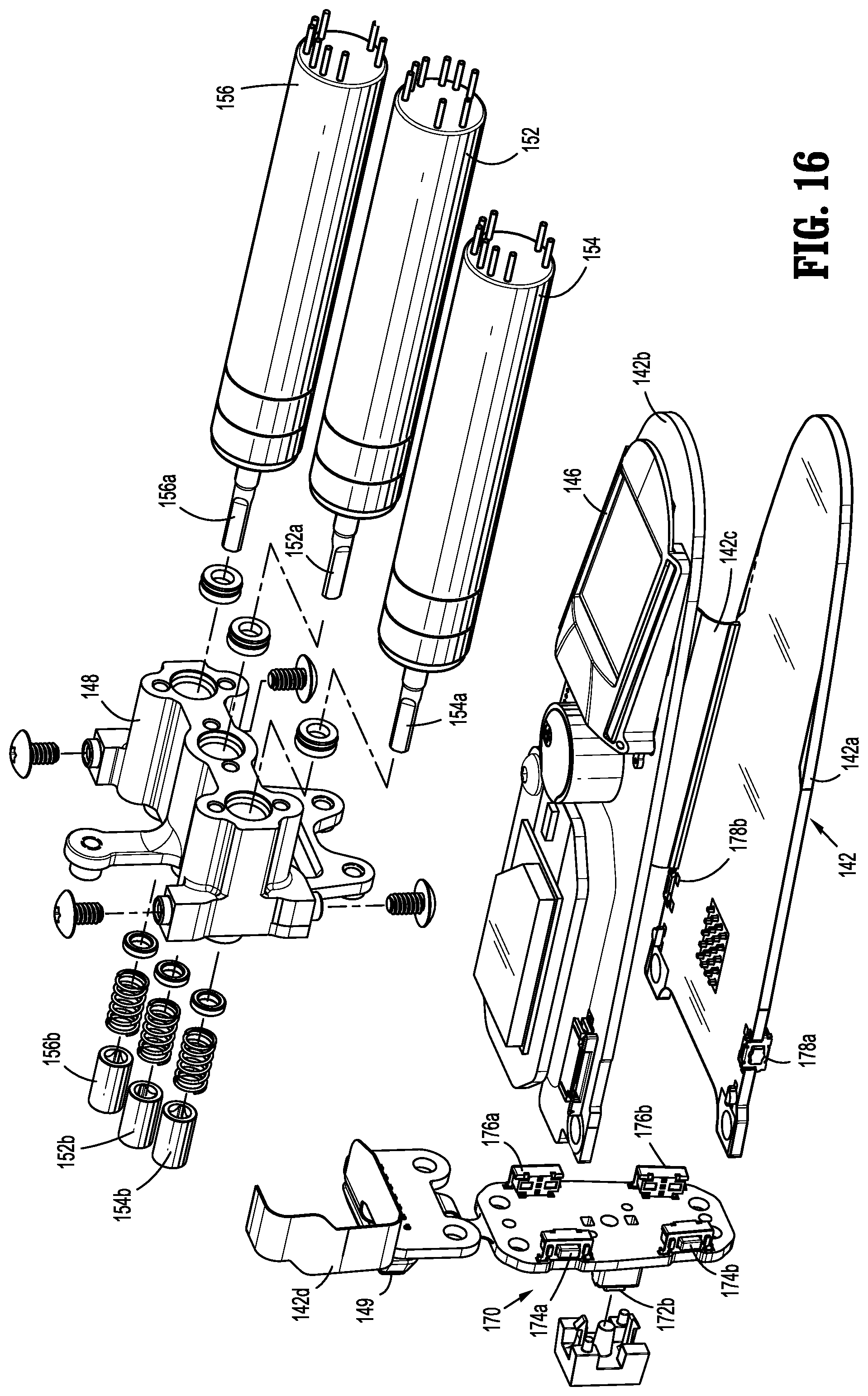
D00013
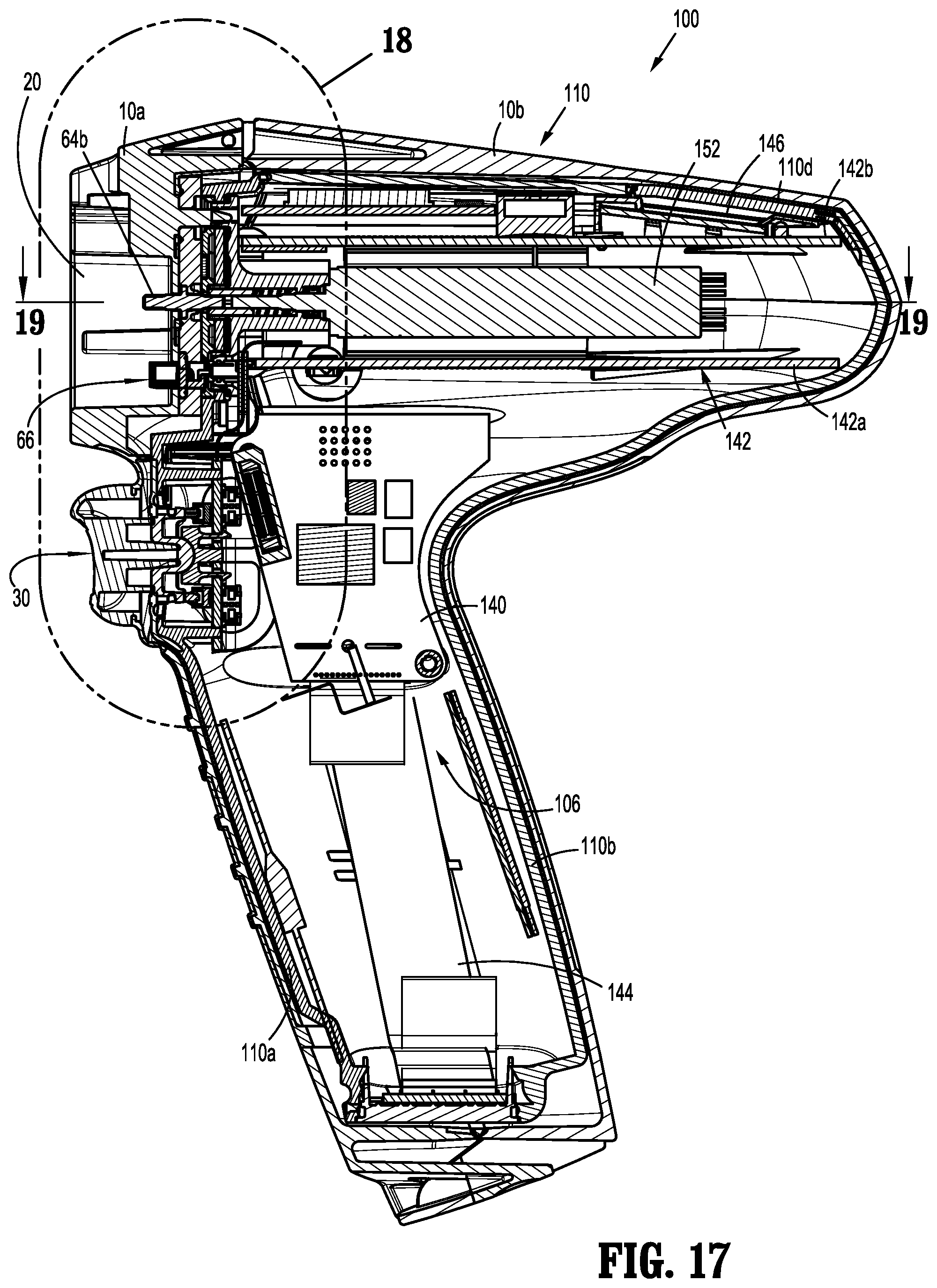
D00014

D00015
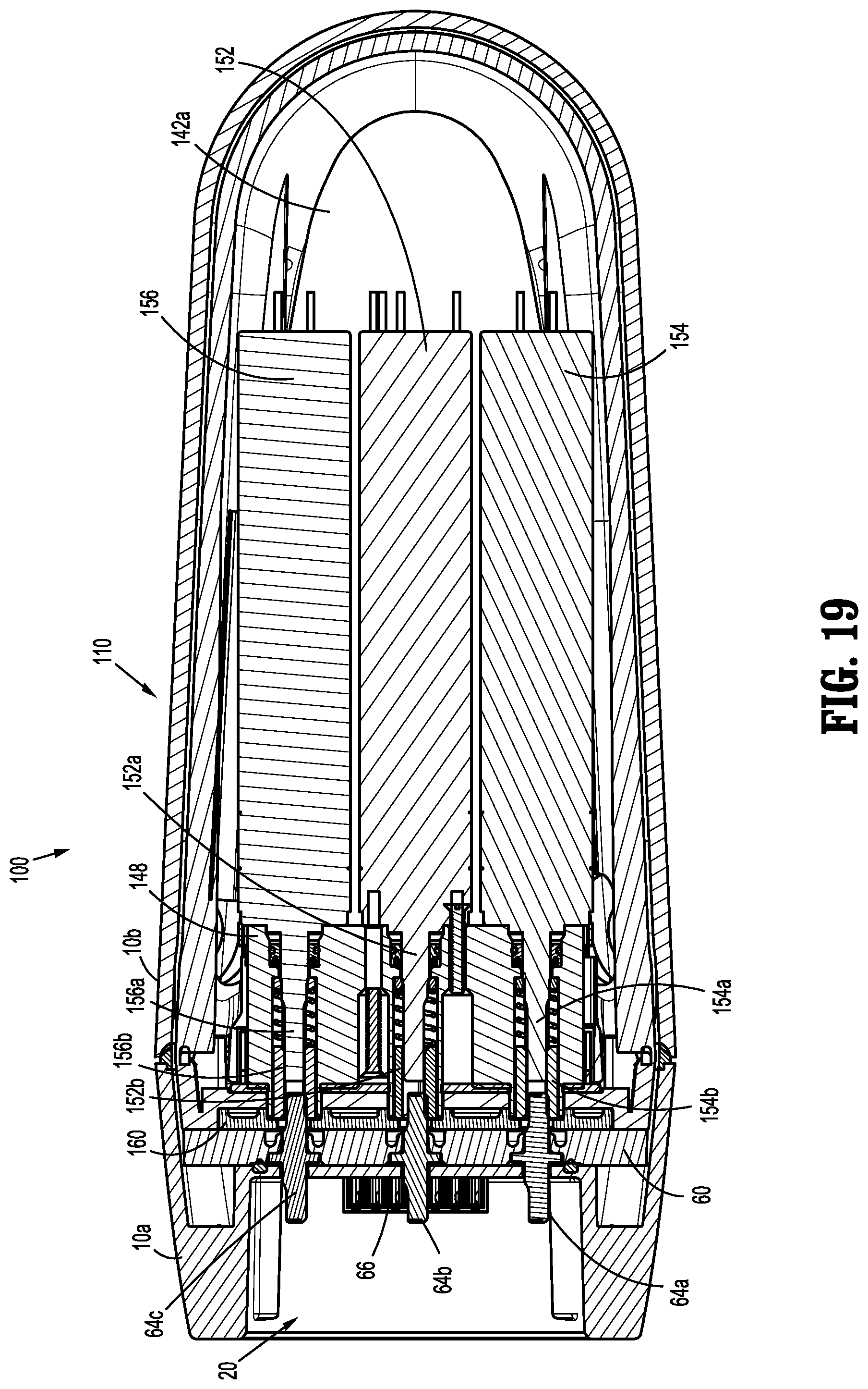
D00016
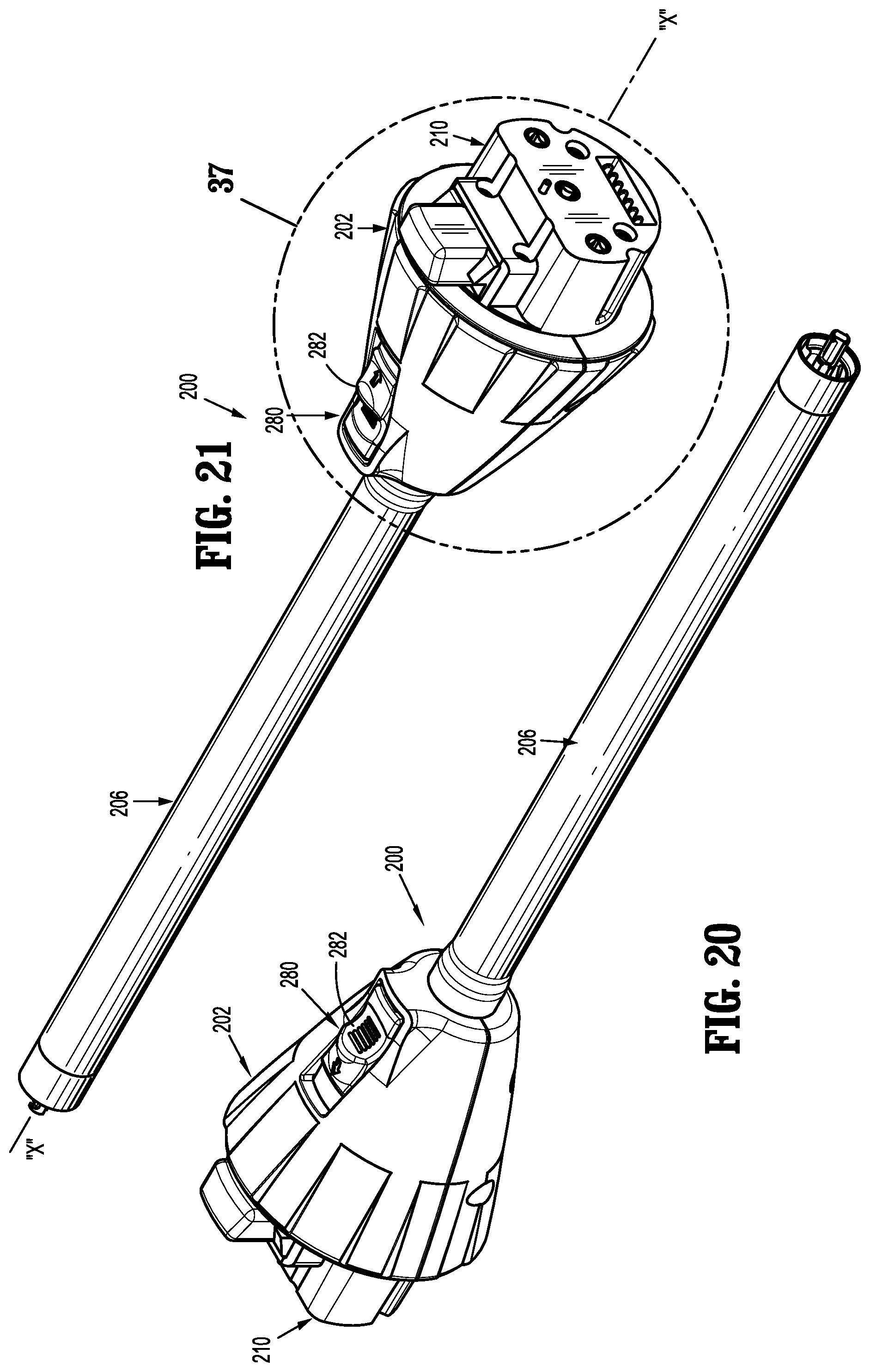
D00017
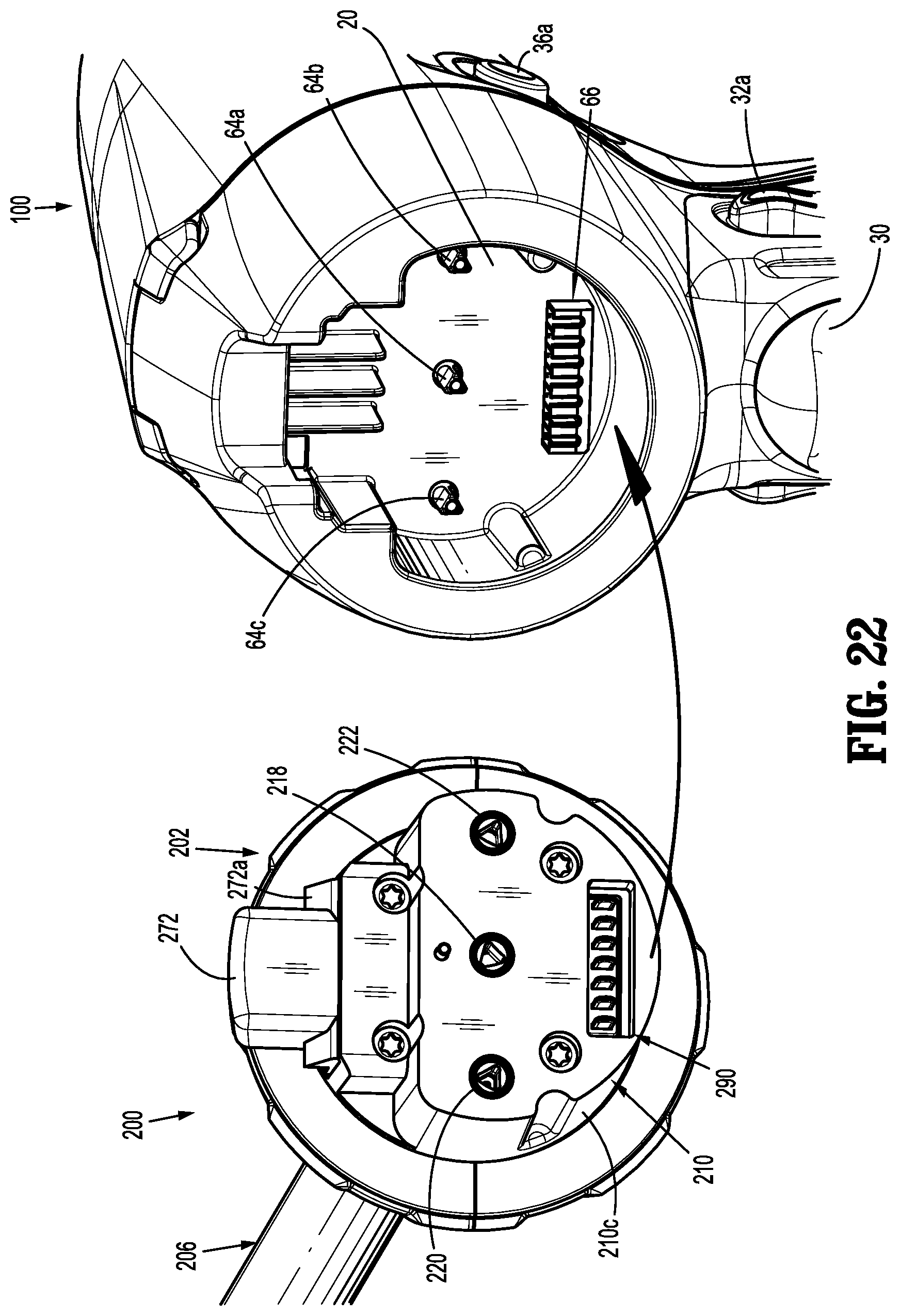
D00018
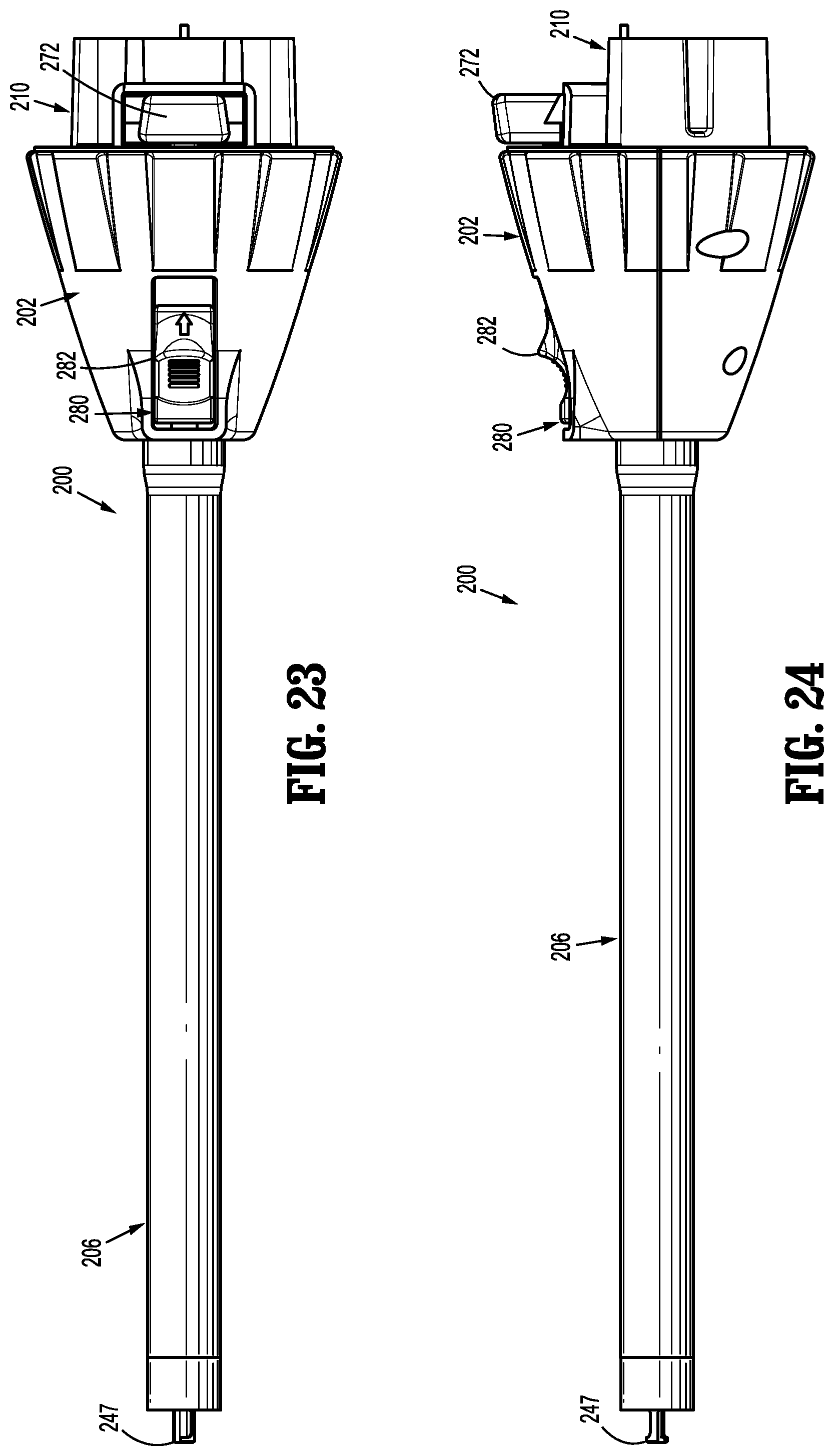
D00019
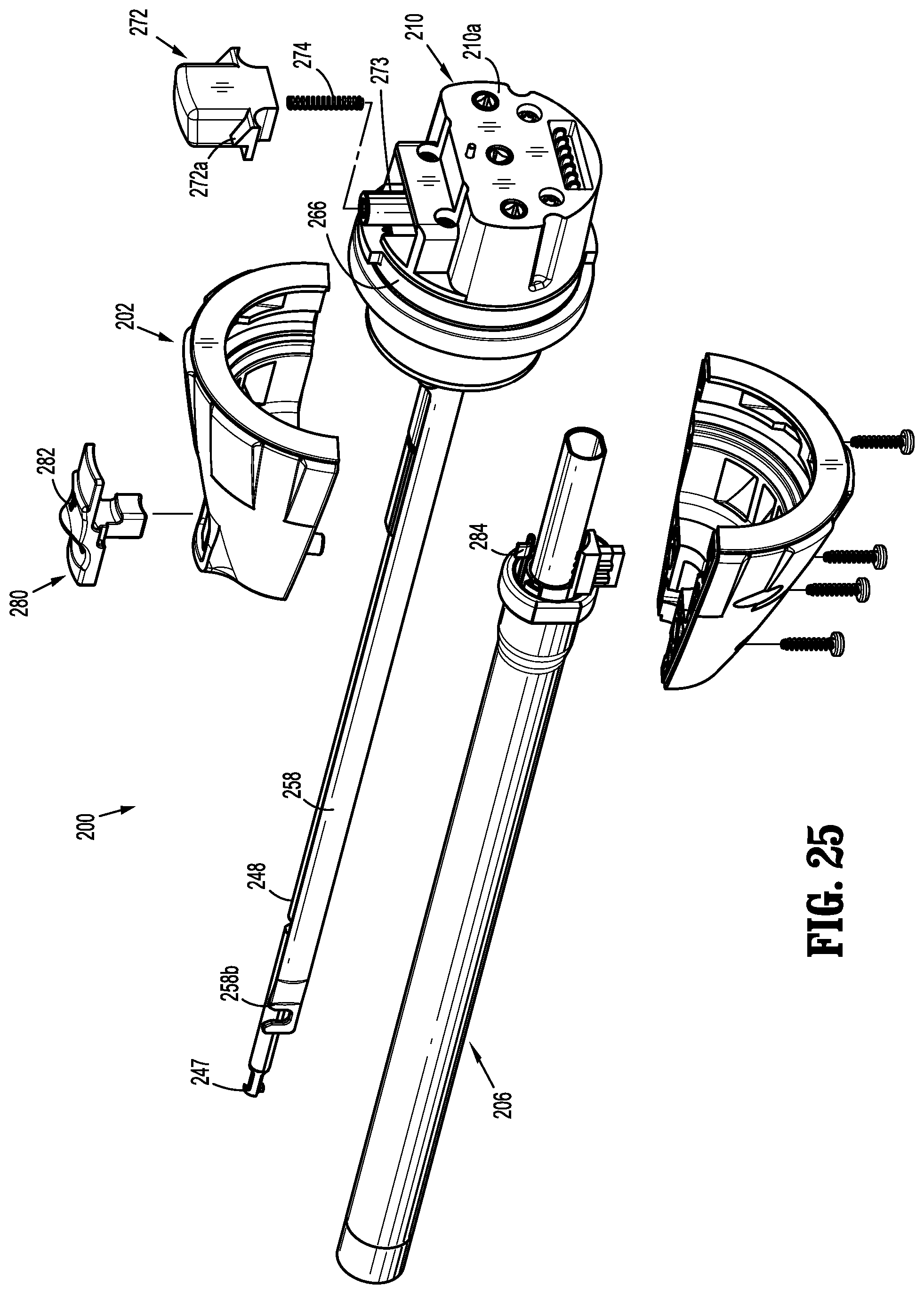
D00020
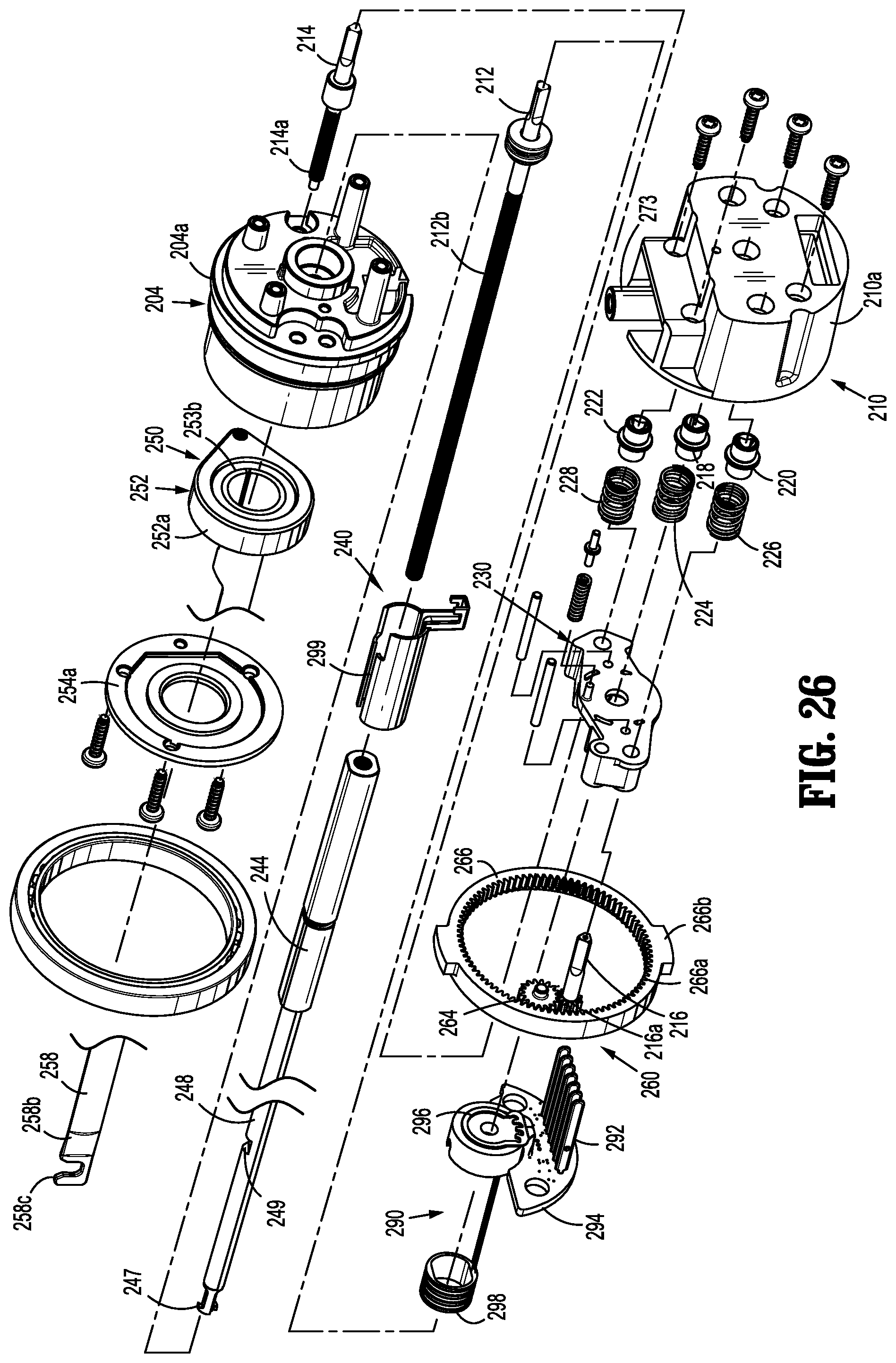
D00021
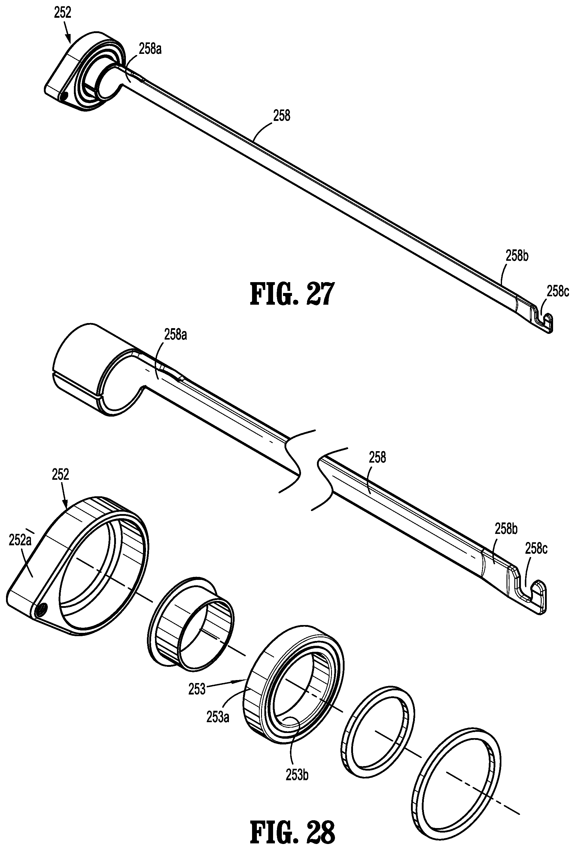
D00022
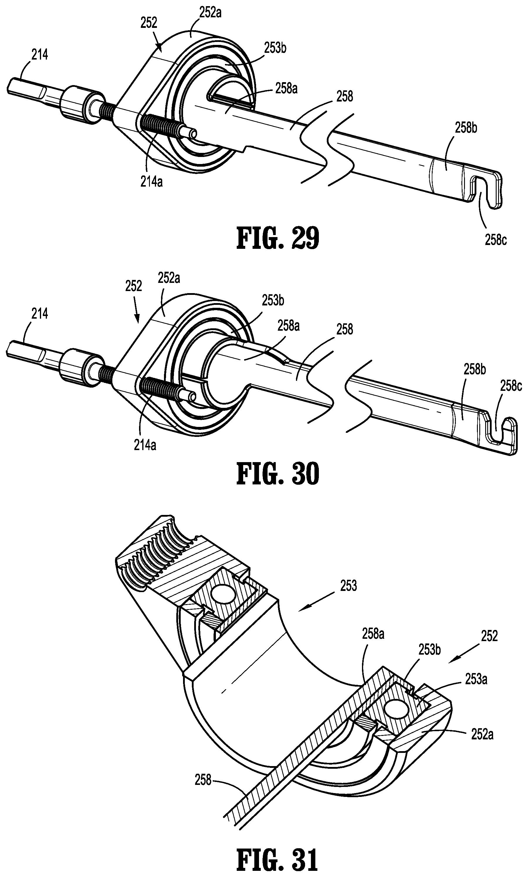
D00023
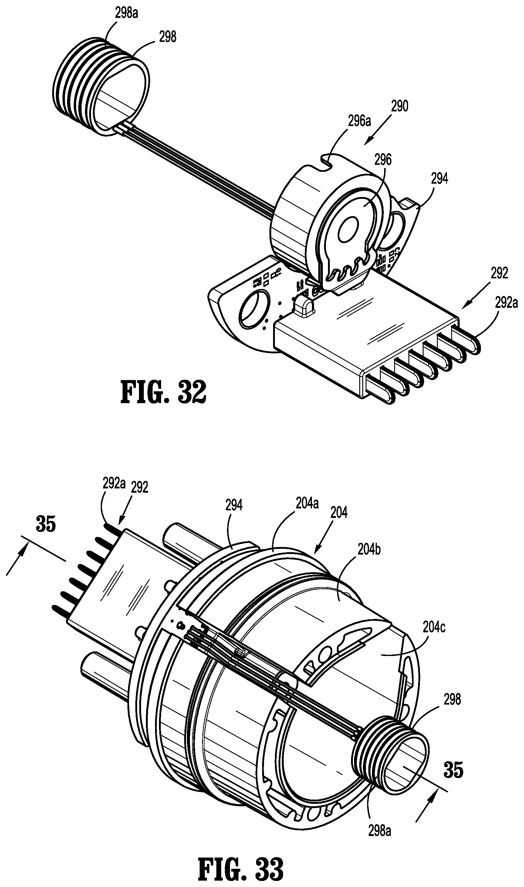
D00024
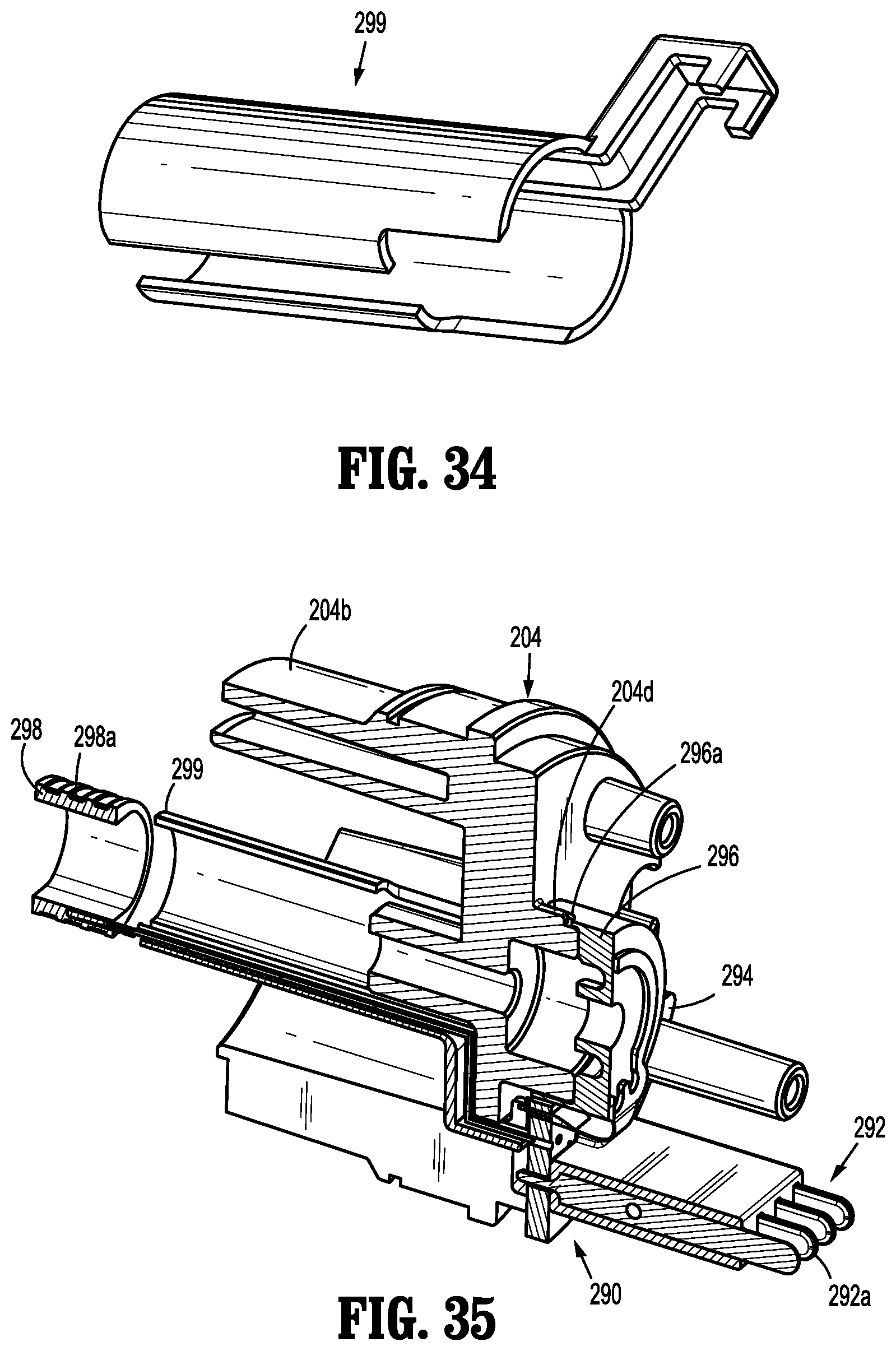
D00025
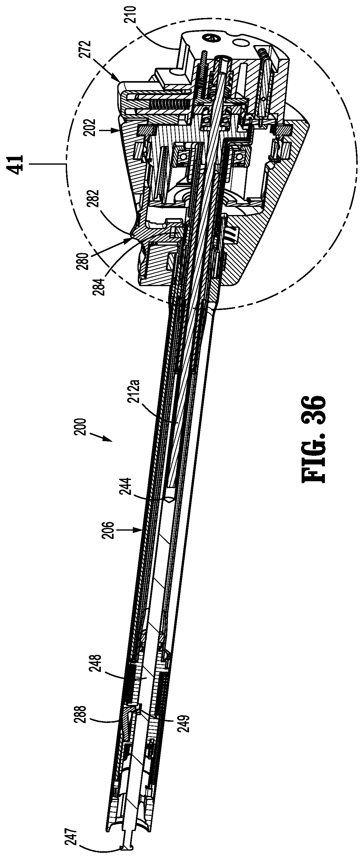
D00026

D00027
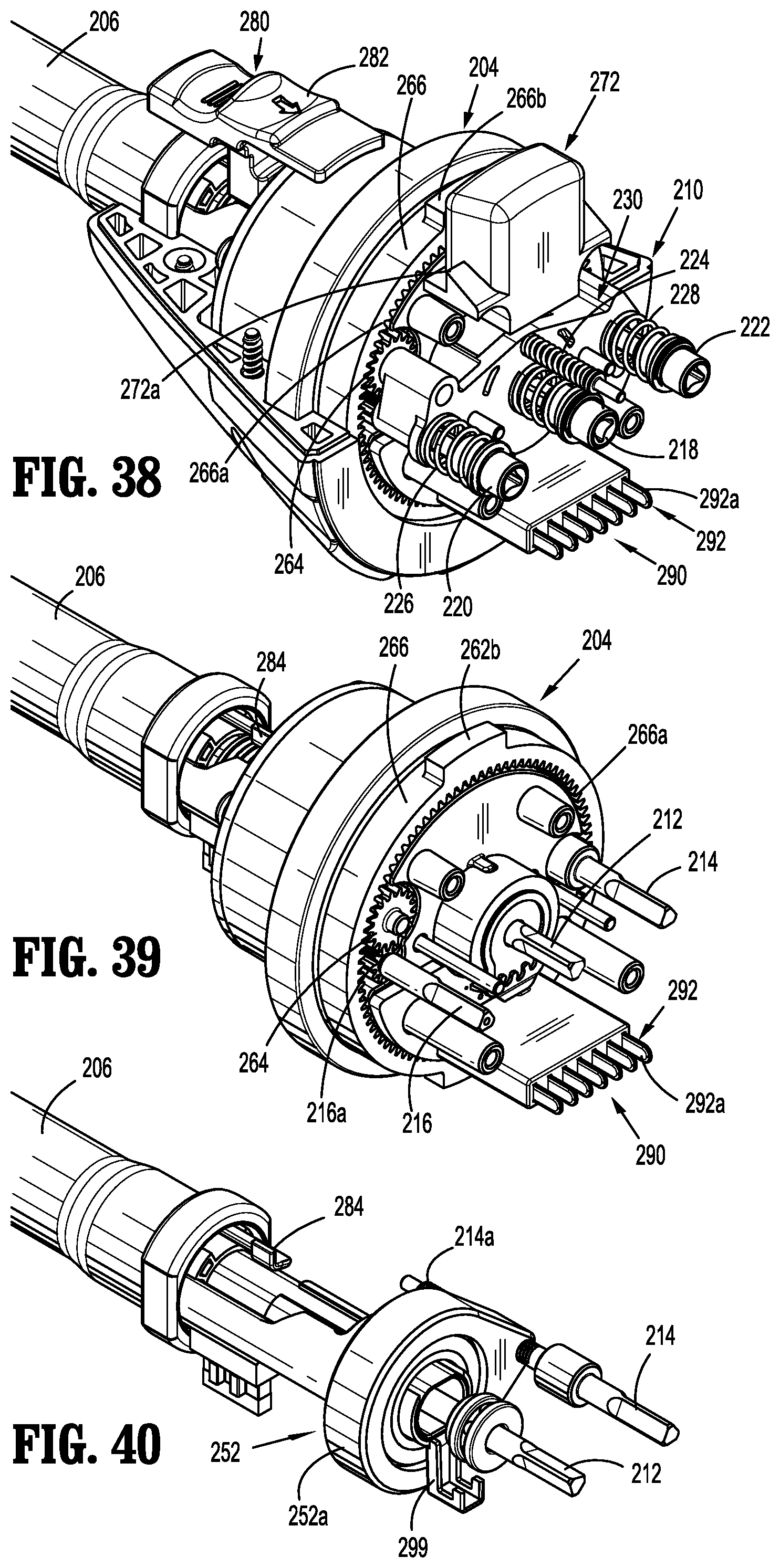
D00028
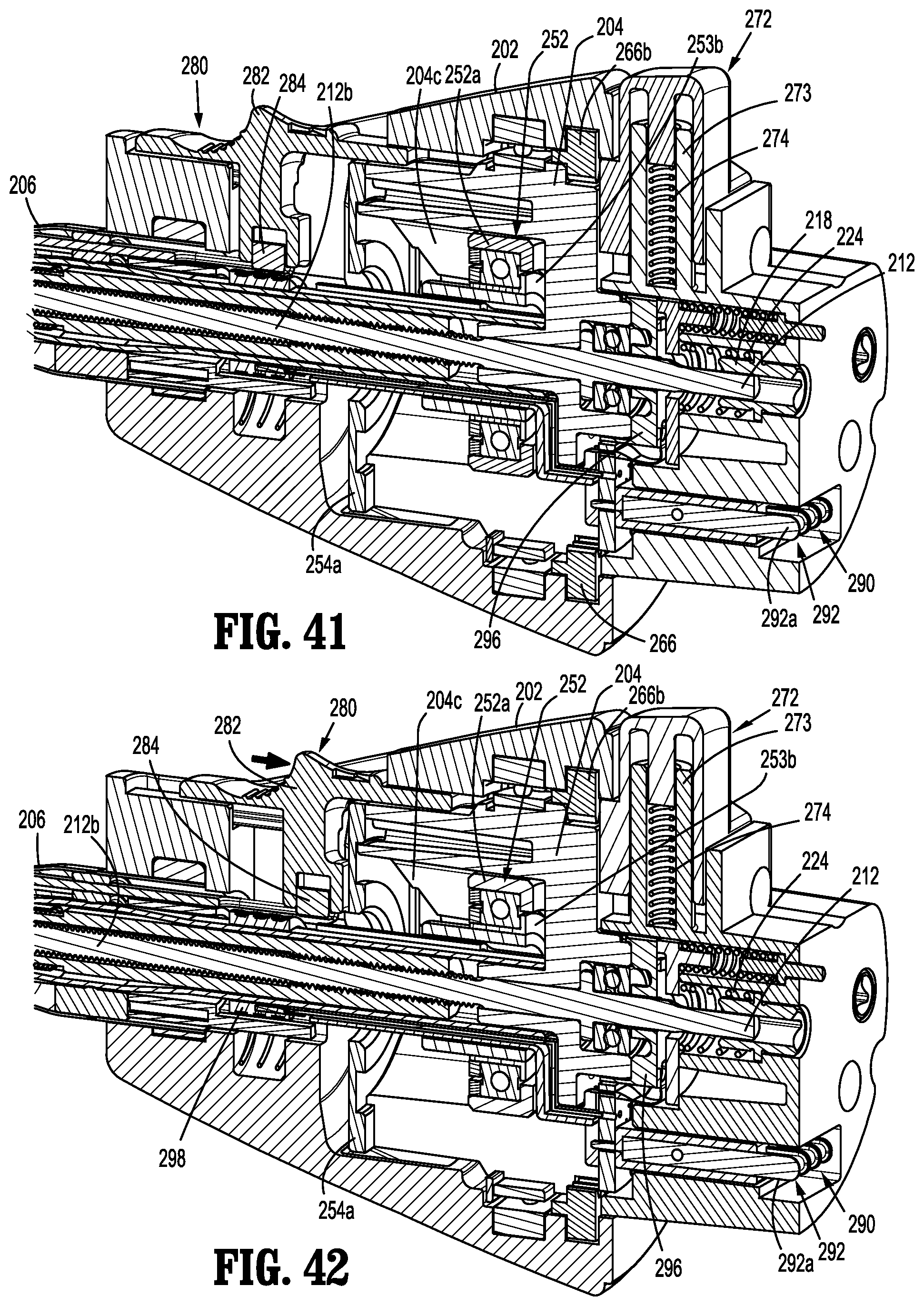
D00029
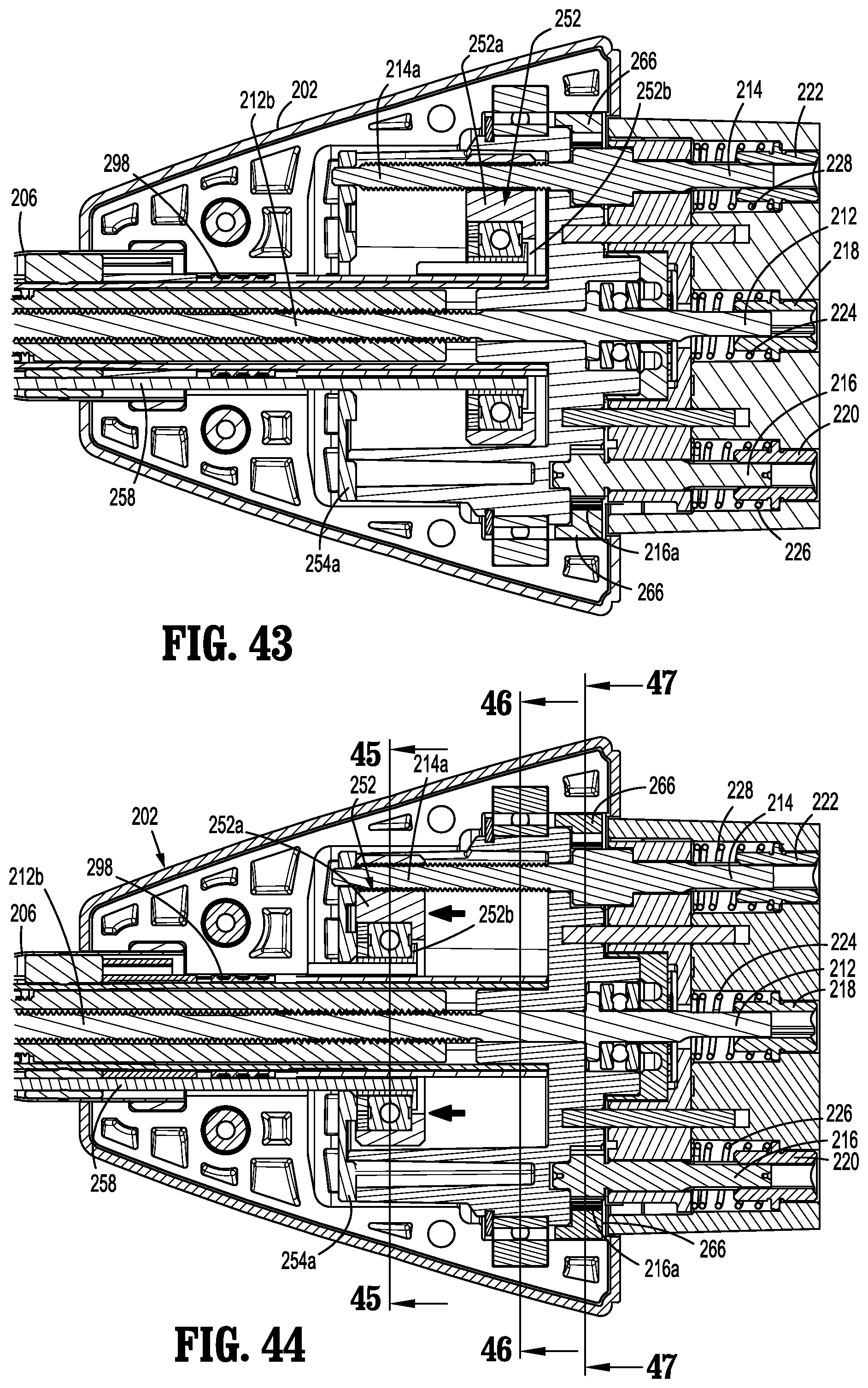
D00030

D00031
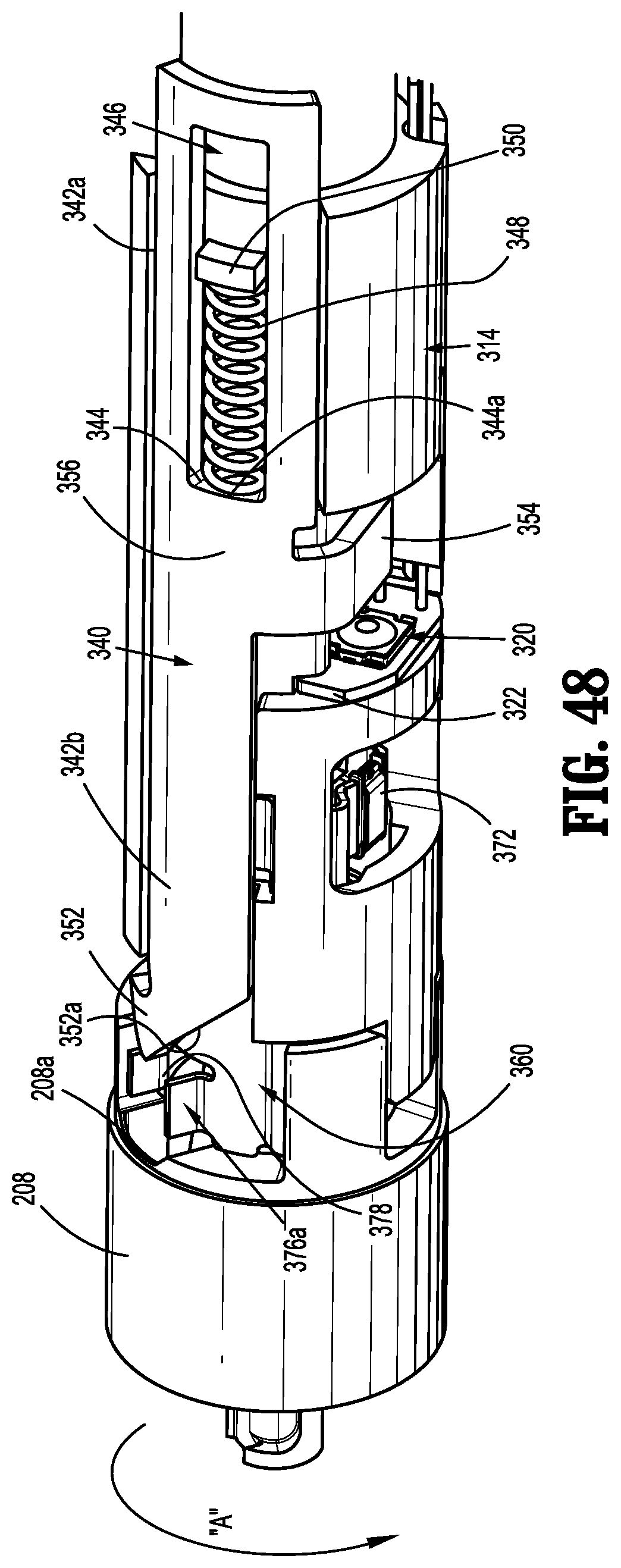
D00032

D00033
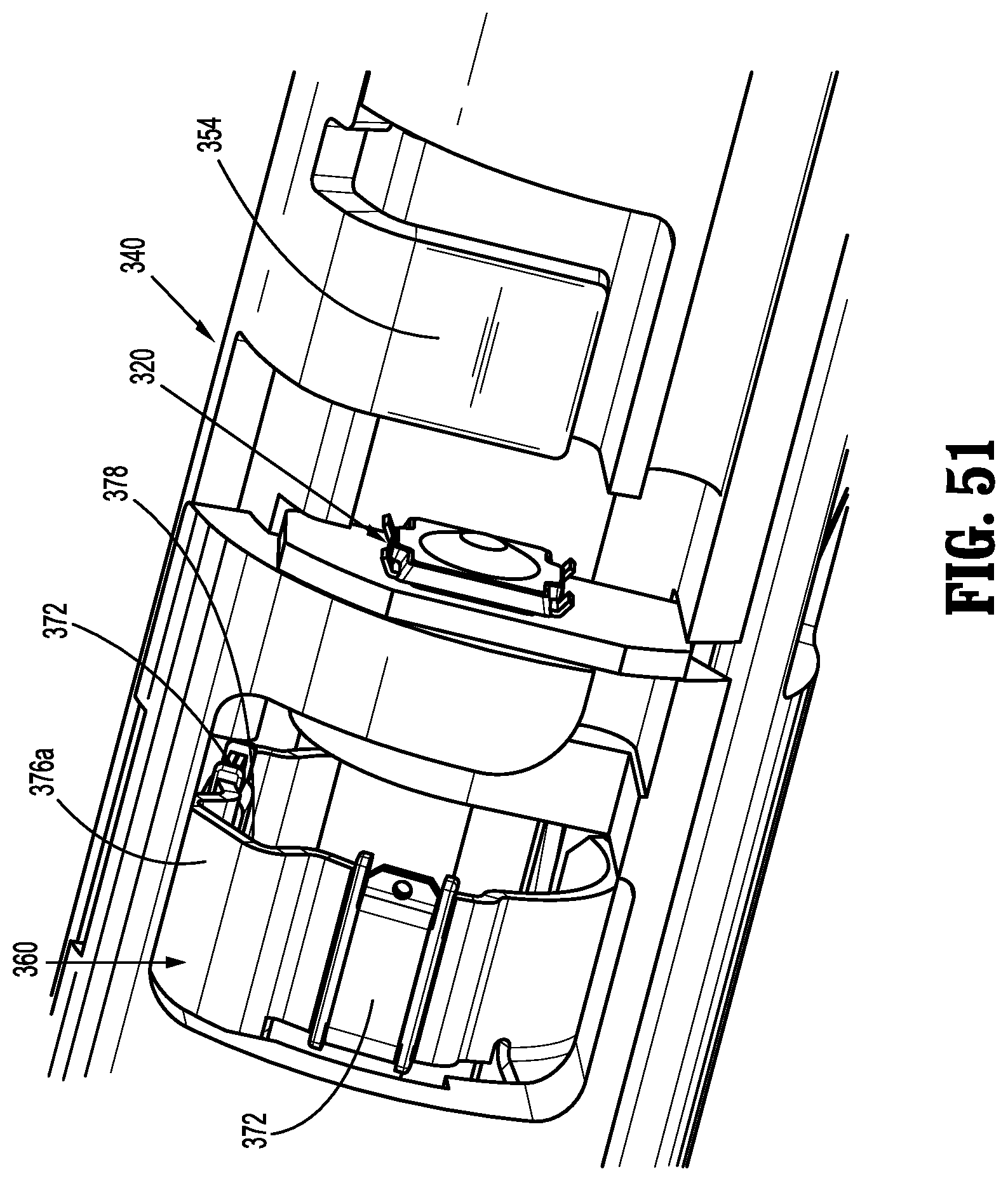
D00034
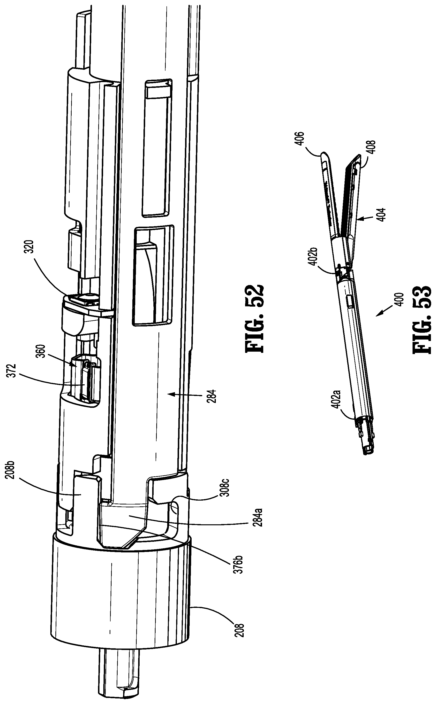
D00035
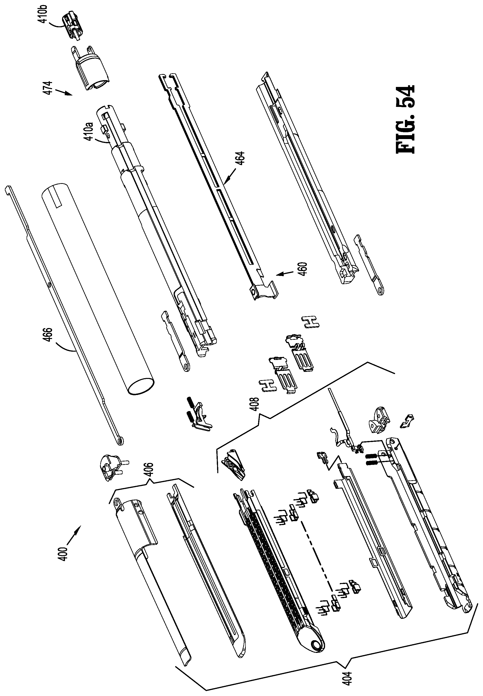
D00036
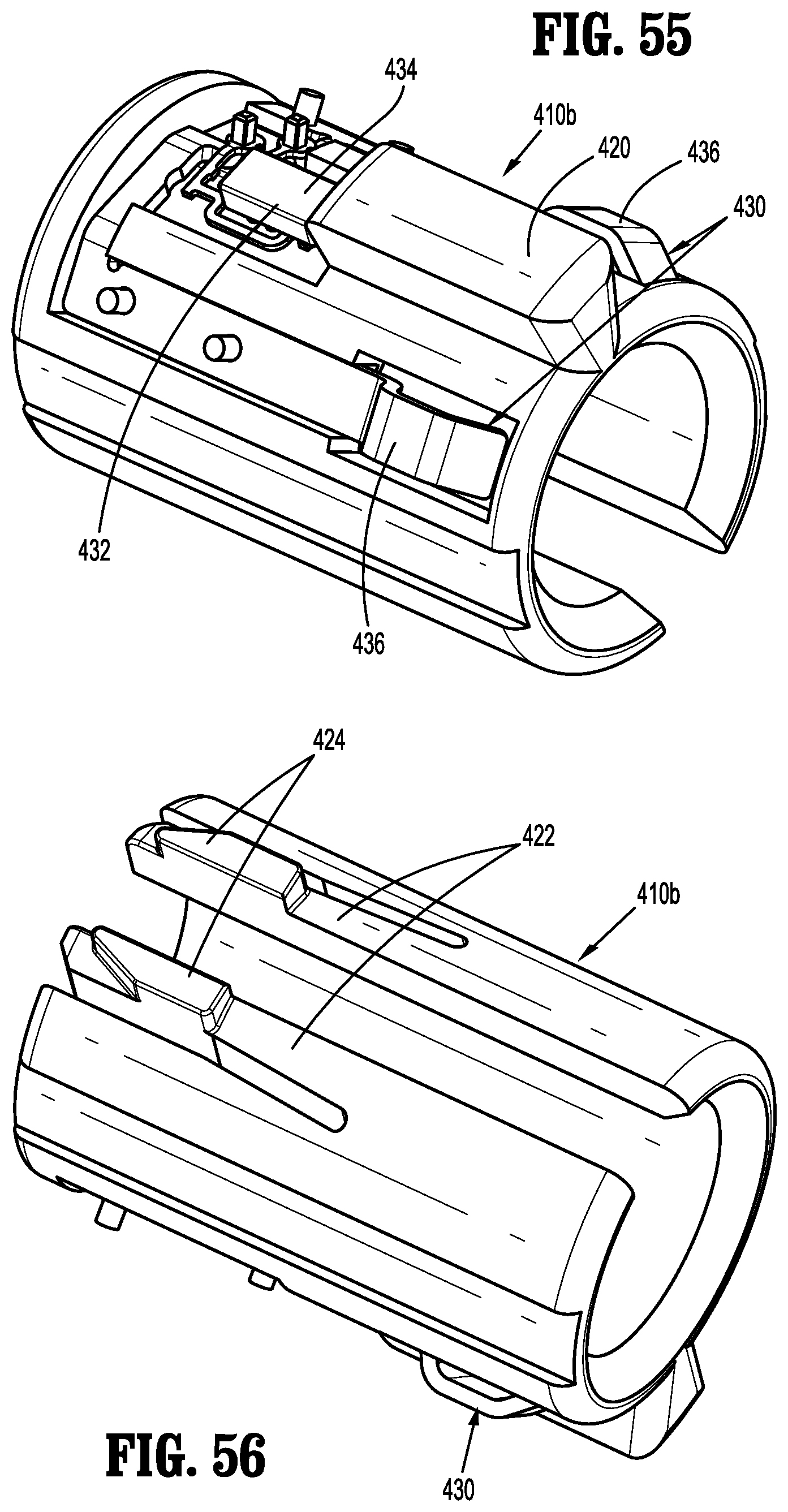
D00037
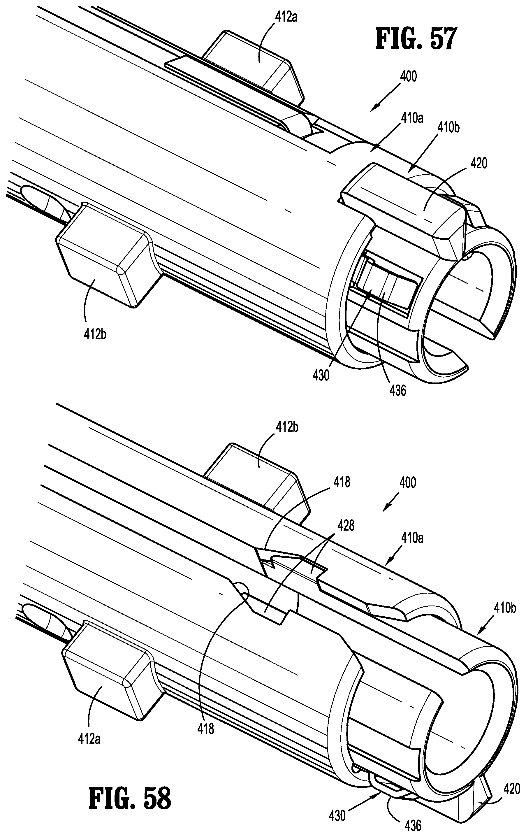
D00038
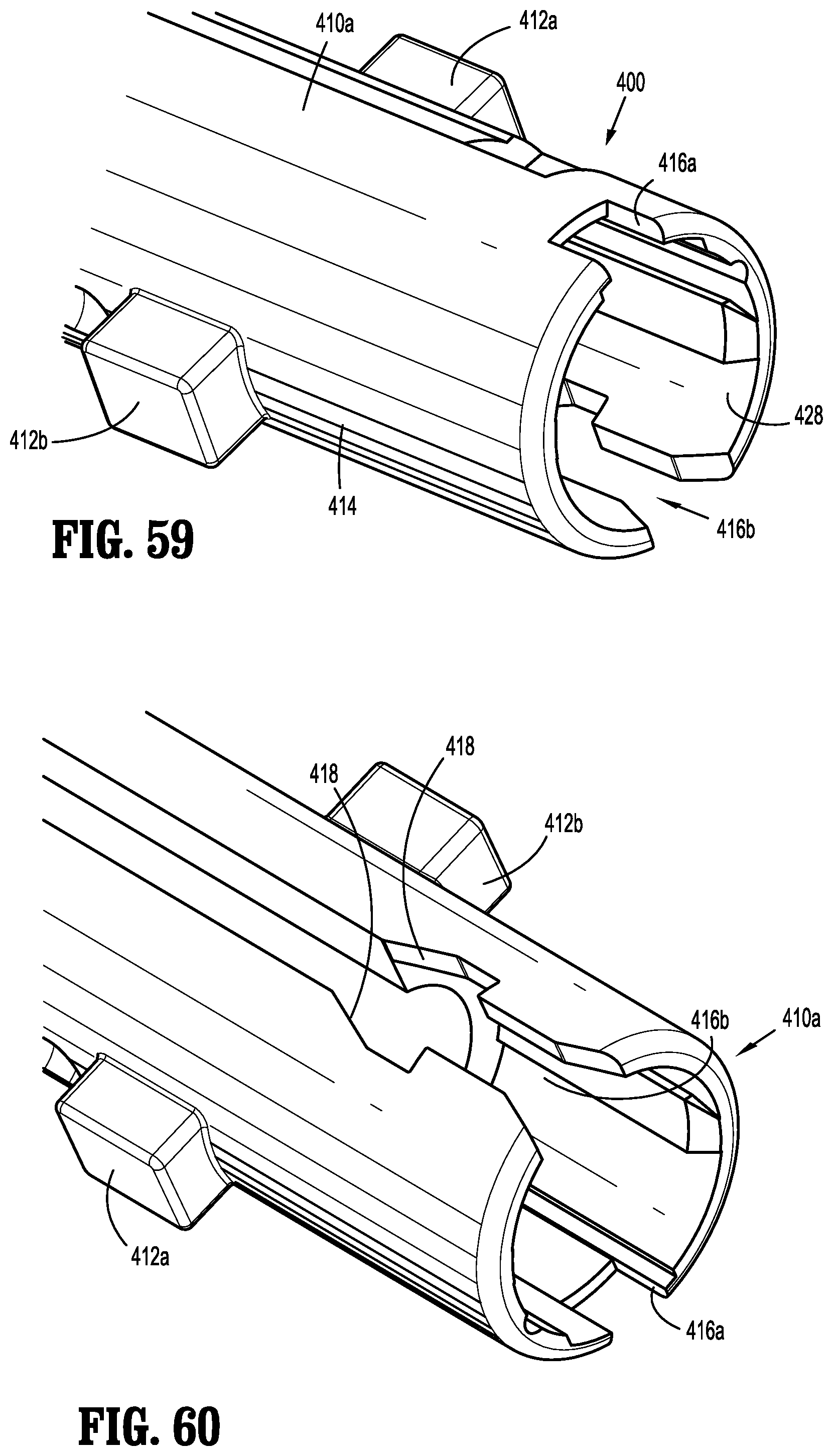
D00039
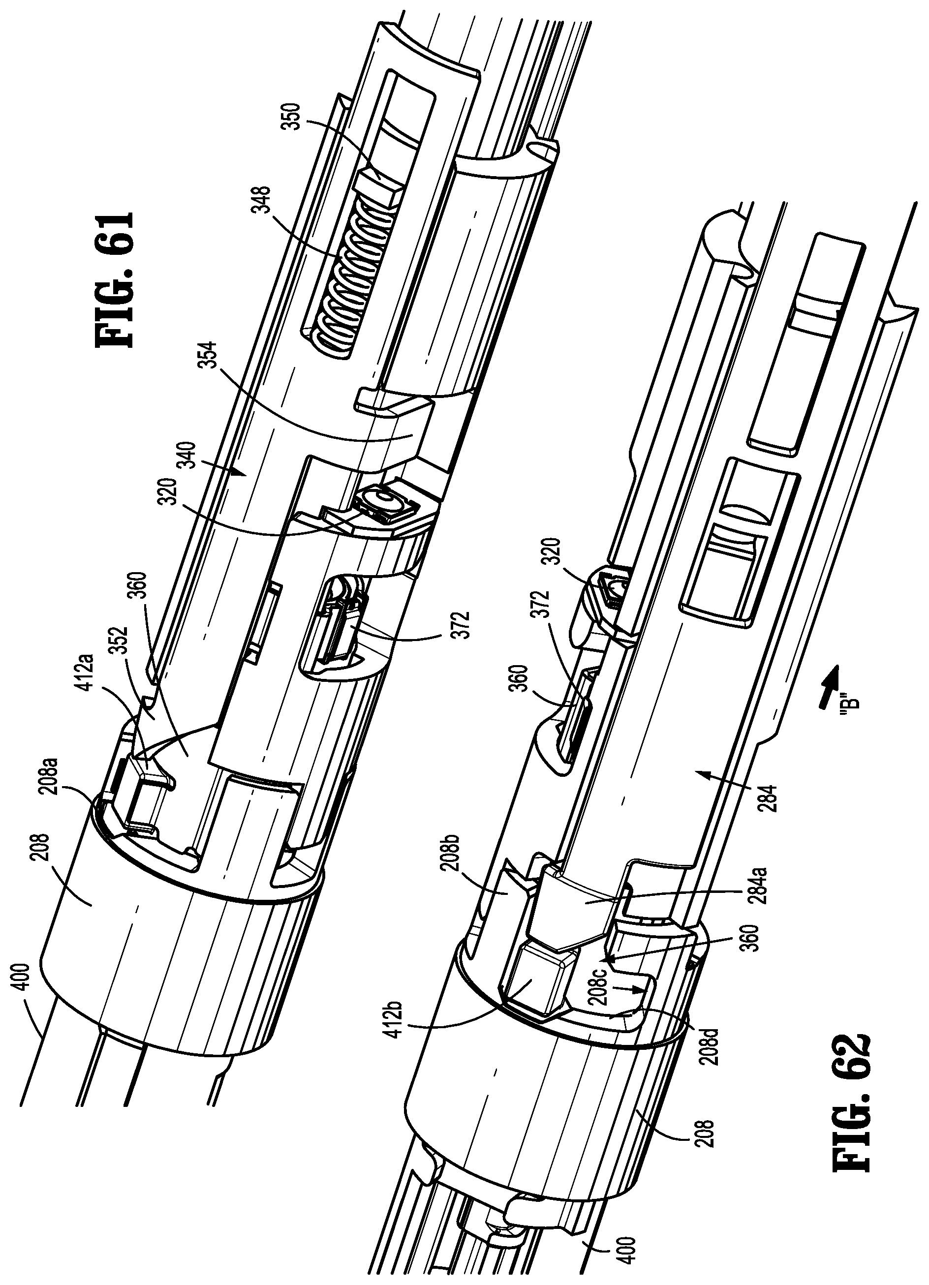
D00040
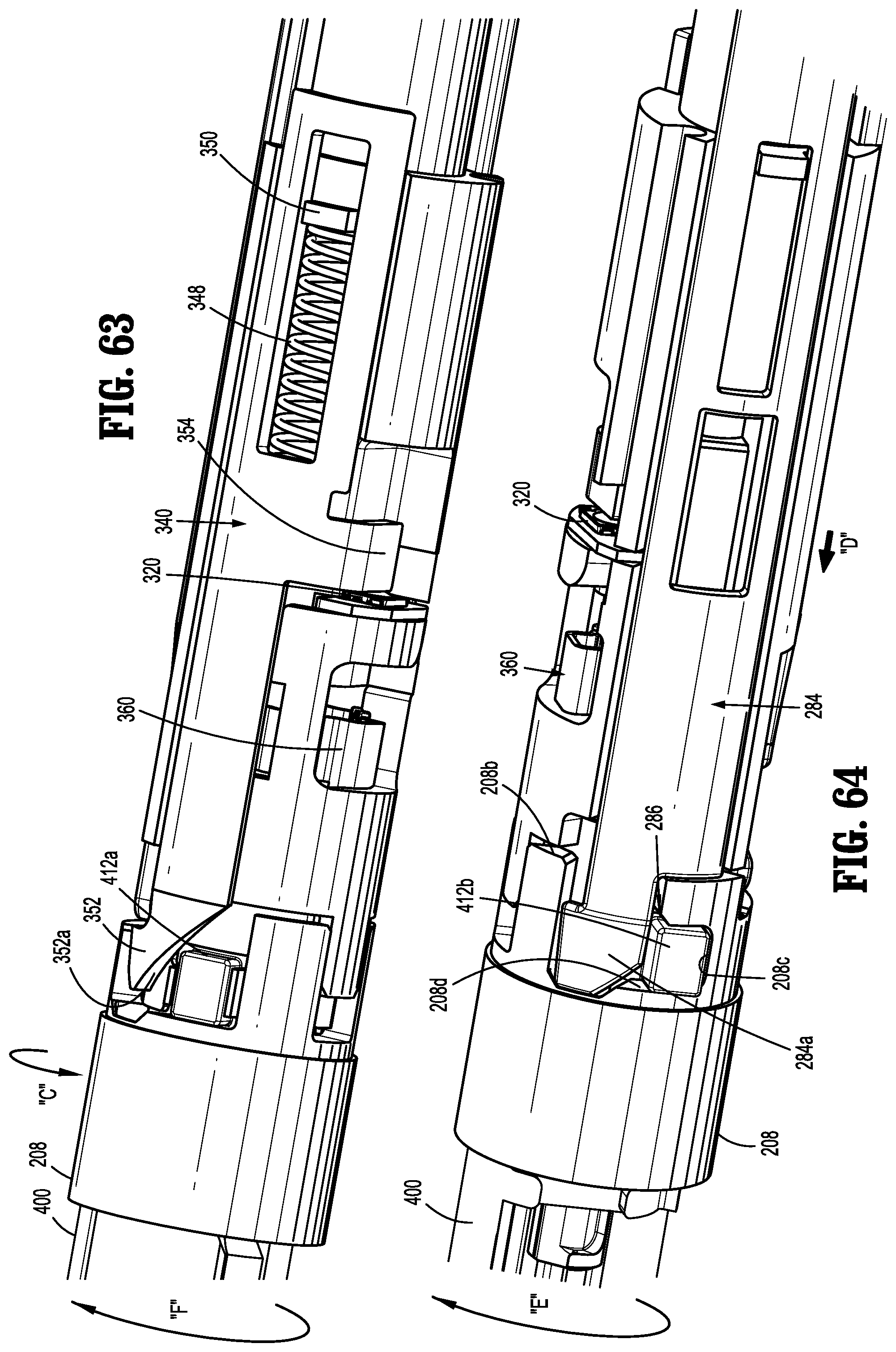
D00041
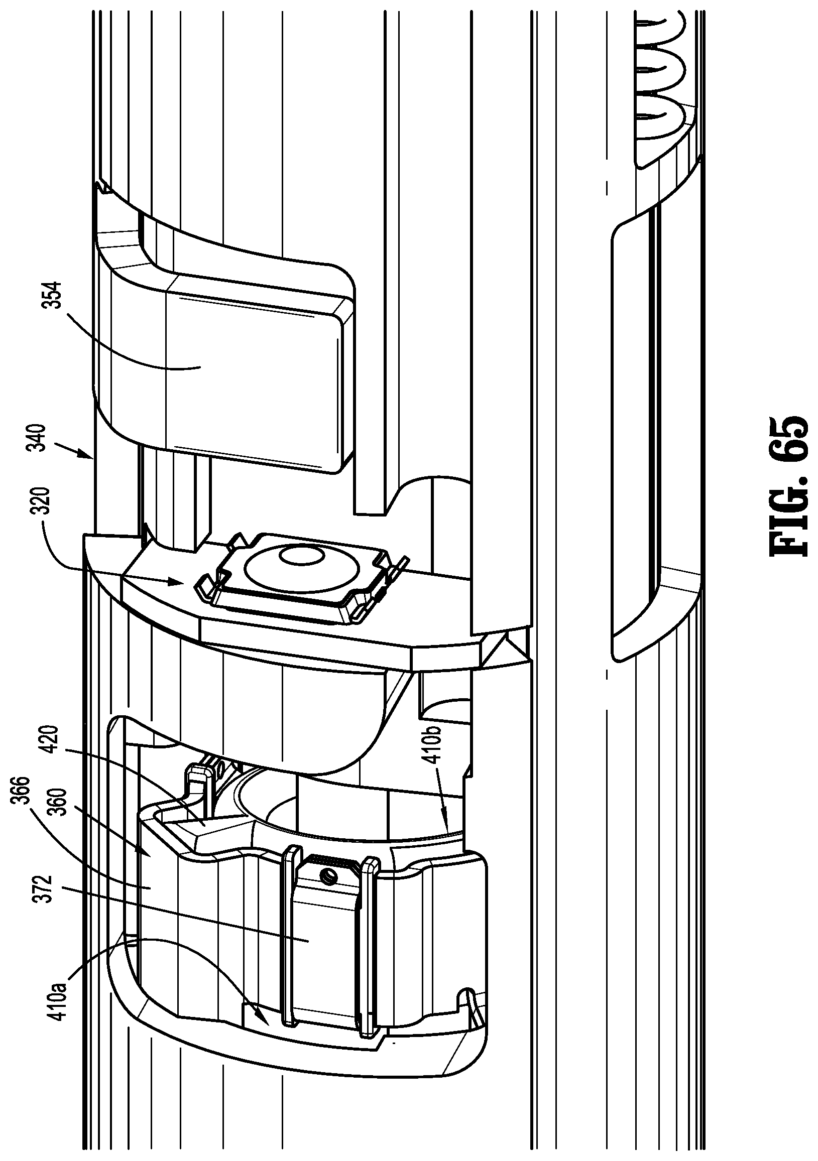
D00042

XML
uspto.report is an independent third-party trademark research tool that is not affiliated, endorsed, or sponsored by the United States Patent and Trademark Office (USPTO) or any other governmental organization. The information provided by uspto.report is based on publicly available data at the time of writing and is intended for informational purposes only.
While we strive to provide accurate and up-to-date information, we do not guarantee the accuracy, completeness, reliability, or suitability of the information displayed on this site. The use of this site is at your own risk. Any reliance you place on such information is therefore strictly at your own risk.
All official trademark data, including owner information, should be verified by visiting the official USPTO website at www.uspto.gov. This site is not intended to replace professional legal advice and should not be used as a substitute for consulting with a legal professional who is knowledgeable about trademark law.