Medical devices with a flexible electrode assembly coupled to an ablation tip
Cheung , et al.
U.S. patent number 10,603,105 [Application Number 14/922,023] was granted by the patent office on 2020-03-31 for medical devices with a flexible electrode assembly coupled to an ablation tip. This patent grant is currently assigned to Boston Scientific Scimed Inc. The grantee listed for this patent is Boston Scientific Scimed Inc.. Invention is credited to Desmond Cheung, Isaac J. Kim, Andrew T. Marecki, Mark D. Mirigian, John C. Potosky.


View All Diagrams
| United States Patent | 10,603,105 |
| Cheung , et al. | March 31, 2020 |
Medical devices with a flexible electrode assembly coupled to an ablation tip
Abstract
Medical devices and methods for making and using medical devices are disclosed. An example medical device may include a catheter for use in cardiac mapping and/or ablation. The catheter may include an elongate catheter shaft having a distal ablation electrode region capable of ablating tissue. An electrode assembly may be coupled to the distal ablation electrode region. The electrode assembly may include a flexible circuit having one or more electrodes disposed thereon.
| Inventors: | Cheung; Desmond (San Jose, CA), Potosky; John C. (San Jose, CA), Marecki; Andrew T. (Shrewsbury, MA), Kim; Isaac J. (San Jose, CA), Mirigian; Mark D. (San Jose, CA) | ||||||||||
|---|---|---|---|---|---|---|---|---|---|---|---|
| Applicant: |
|
||||||||||
| Assignee: | Boston Scientific Scimed Inc
(Maple Grove, MN) |
||||||||||
| Family ID: | 54364774 | ||||||||||
| Appl. No.: | 14/922,023 | ||||||||||
| Filed: | October 23, 2015 |
Prior Publication Data
| Document Identifier | Publication Date | |
|---|---|---|
| US 20160113712 A1 | Apr 28, 2016 | |
Related U.S. Patent Documents
| Application Number | Filing Date | Patent Number | Issue Date | ||
|---|---|---|---|---|---|
| 62068334 | Oct 24, 2014 | ||||
| Current U.S. Class: | 1/1 |
| Current CPC Class: | A61B 5/6852 (20130101); A61B 5/6859 (20130101); A61B 5/0422 (20130101); A61B 18/1492 (20130101); A61B 2018/00642 (20130101); A61B 2018/00351 (20130101); A61B 2018/1495 (20130101); A61B 2018/1465 (20130101); A61B 2562/166 (20130101); A61B 2018/00577 (20130101); A61B 2017/00526 (20130101); A61B 2018/00839 (20130101) |
| Current International Class: | A61B 18/14 (20060101); A61B 5/042 (20060101); A61B 5/00 (20060101); A61B 17/00 (20060101); A61B 18/00 (20060101) |
References Cited [Referenced By]
U.S. Patent Documents
| 3773401 | November 1973 | Douklias et al. |
| 4466443 | August 1984 | Utsugi |
| 4602624 | July 1986 | Naples et al. |
| 4633882 | January 1987 | Matsuo et al. |
| 4732149 | March 1988 | Sutter |
| 4745928 | May 1988 | Webler et al. |
| 4763660 | August 1988 | Kroll et al. |
| 4966145 | October 1990 | Kikumoto et al. |
| 5019076 | May 1991 | Yamanashi et al. |
| 5029588 | July 1991 | Yock et al. |
| 5114423 | May 1992 | Kasprzyk et al. |
| 5178150 | January 1993 | Silverstein et al. |
| 5217460 | June 1993 | Knoepfler |
| 5238004 | August 1993 | Sahatjian et al. |
| 5240003 | August 1993 | Lancee et al. |
| 5242441 | September 1993 | Avitall |
| 5254088 | October 1993 | Lundquist et al. |
| 5277201 | January 1994 | Stern |
| 5295482 | March 1994 | Clare et al. |
| 5318589 | June 1994 | Lichtman |
| 5324284 | June 1994 | Imran |
| 5331966 | July 1994 | Bennett et al. |
| 5334193 | August 1994 | Nardella |
| 5341807 | August 1994 | Nardella |
| 5377685 | January 1995 | Kazi et al. |
| 5383874 | January 1995 | Jackson et al. |
| 5385146 | January 1995 | Goldreyer |
| 5385148 | January 1995 | Lesh et al. |
| 5391199 | February 1995 | Ben-Haim |
| 5398683 | March 1995 | Edwards et al. |
| 5415654 | May 1995 | Daikuzono |
| 5417689 | May 1995 | Fine |
| 5423811 | June 1995 | Imran et al. |
| 5447529 | September 1995 | Marchlinski et al. |
| 5456682 | October 1995 | Edwards et al. |
| 5462521 | October 1995 | Brucker et al. |
| 5482054 | January 1996 | Slater et al. |
| 5485849 | January 1996 | Panescu et al. |
| 5494042 | February 1996 | Panescu et al. |
| 5500012 | March 1996 | Brucker et al. |
| 5520683 | May 1996 | Subramaniam et al. |
| 5571088 | November 1996 | Lennox et al. |
| 5573535 | November 1996 | Viklund |
| 5575772 | November 1996 | Lennox |
| 5579764 | December 1996 | Goldreyer |
| 5582609 | December 1996 | Swanson et al. |
| 5647870 | July 1997 | Kordis et al. |
| 5718701 | February 1998 | Shai et al. |
| 5722402 | March 1998 | Swanson et al. |
| 5735846 | April 1998 | Panescu et al. |
| 5762067 | June 1998 | Dunham et al. |
| 5788636 | August 1998 | Curley |
| 5792064 | August 1998 | Panescu et al. |
| 5800482 | September 1998 | Pomeranz et al. |
| 5820568 | October 1998 | Willis |
| 5830213 | November 1998 | Panescu et al. |
| 5833621 | November 1998 | Panescu et al. |
| 5836990 | November 1998 | Li |
| 5868735 | February 1999 | Lafontaine |
| 5871483 | February 1999 | Jackson et al. |
| 5871526 | February 1999 | Gibbs et al. |
| 5876336 | March 1999 | Swanson et al. |
| 5885278 | March 1999 | Fleischman |
| 5913856 | June 1999 | Chia et al. |
| 5916213 | June 1999 | Haissaguerre et al. |
| 5957850 | September 1999 | Marian et al. |
| 6004269 | December 1999 | Crowley et al. |
| 6027500 | February 2000 | Buckles et al. |
| 6050267 | April 2000 | Nardella et al. |
| 6050994 | April 2000 | Sherman |
| 6059778 | May 2000 | Sherman |
| 6063078 | May 2000 | Wittkampf |
| 6064905 | May 2000 | Webster, Jr. et al. |
| 6068629 | May 2000 | Haissaguerre et al. |
| 6070094 | May 2000 | Swanson et al. |
| 6071281 | June 2000 | Burnside |
| 6083170 | July 2000 | Ben-Haim |
| 6083222 | July 2000 | Klein et al. |
| 6099524 | August 2000 | Lipson et al. |
| 6101409 | August 2000 | Swanson et al. |
| 6116027 | September 2000 | Smith et al. |
| 6120476 | September 2000 | Fung et al. |
| 6165123 | December 2000 | Thompson |
| 6171305 | January 2001 | Sherman |
| 6200314 | March 2001 | Sherman |
| 6206831 | March 2001 | Suorsa et al. |
| 6210337 | April 2001 | Dunham et al. |
| 6216027 | April 2001 | Willis et al. |
| 6224557 | May 2001 | Ziel et al. |
| 6233491 | May 2001 | Kordis et al. |
| 6241754 | June 2001 | Swanson et al. |
| 6270493 | August 2001 | Lalonde et al. |
| 6290697 | September 2001 | Tu et al. |
| 6352534 | March 2002 | Paddock et al. |
| 6395325 | May 2002 | Hedge et al. |
| 6400981 | June 2002 | Govari |
| 6423002 | July 2002 | Hossack |
| 6475213 | November 2002 | Whayne et al. |
| 6488678 | December 2002 | Sherman |
| 6491710 | December 2002 | Satake |
| 6500174 | December 2002 | Maguire et al. |
| 6508767 | January 2003 | Burns et al. |
| 6508769 | January 2003 | Bonnefous |
| 6508803 | January 2003 | Horikawa et al. |
| 6514249 | February 2003 | Maguire et al. |
| 6516667 | February 2003 | Broad et al. |
| 6517533 | February 2003 | Swaminathan |
| 6517534 | February 2003 | McGovern et al. |
| 6537271 | March 2003 | Murray et al. |
| 6544175 | April 2003 | Newman |
| 6546270 | April 2003 | Goldin et al. |
| 6547788 | April 2003 | Maguire et al. |
| 6569160 | May 2003 | Goldin et al. |
| 6572547 | June 2003 | Miller et al. |
| 6575966 | June 2003 | Lane et al. |
| 6575969 | June 2003 | Rittman et al. |
| 6579278 | June 2003 | Bencini |
| 6582372 | June 2003 | Poland |
| 6584345 | June 2003 | Govari |
| 6589182 | July 2003 | Loftman et al. |
| 6592525 | July 2003 | Miller et al. |
| 6602242 | August 2003 | Fung et al. |
| 6620103 | September 2003 | Bruce et al. |
| 6632179 | October 2003 | Wilson et al. |
| 6638222 | October 2003 | Chandrasekaran et al. |
| 6640120 | October 2003 | Swanson et al. |
| 6647281 | November 2003 | Morency |
| 6656174 | December 2003 | Hegde et al. |
| 6658279 | December 2003 | Swanson et al. |
| 6663573 | December 2003 | Goldin |
| 6666862 | December 2003 | Jain et al. |
| 6673067 | January 2004 | Peyman |
| 6676606 | January 2004 | Simpson et al. |
| 6692441 | February 2004 | Poland et al. |
| 6705992 | March 2004 | Gatzke |
| 6709396 | March 2004 | Flesch et al. |
| 6711429 | March 2004 | Gilboa et al. |
| 6719756 | April 2004 | Muntermann |
| 6723094 | April 2004 | Desinger |
| 6735465 | May 2004 | Panescu |
| 6736814 | May 2004 | Manna et al. |
| 6743174 | June 2004 | Ng et al. |
| 6773402 | August 2004 | Govari et al. |
| 6776758 | August 2004 | Peszynski et al. |
| 6796979 | September 2004 | Lentz |
| 6796980 | September 2004 | Hall |
| 6804545 | October 2004 | Fuimaono et al. |
| 6811550 | November 2004 | Holland et al. |
| 6824517 | November 2004 | Salgo et al. |
| 6837884 | January 2005 | Woloszko |
| 6845257 | January 2005 | Fuimaono et al. |
| 6845264 | January 2005 | Skladnev et al. |
| 6917834 | July 2005 | Koblish et al. |
| 6922579 | July 2005 | Taimisto et al. |
| 6923808 | August 2005 | Taimisto |
| 6932811 | August 2005 | Hooven et al. |
| 6945938 | September 2005 | Grunwald |
| 6950689 | September 2005 | Willis et al. |
| 6952615 | October 2005 | Satake |
| 6958040 | October 2005 | Oliver et al. |
| 7001383 | February 2006 | Keidar |
| 7037264 | May 2006 | Poland |
| 7047068 | May 2006 | Haissaguerre |
| 7097643 | August 2006 | Cornelius et al. |
| 7099711 | August 2006 | Fuimaono et al. |
| 7105122 | September 2006 | Karason |
| 7112198 | September 2006 | Satake |
| 7115122 | October 2006 | Swanson et al. |
| 7123951 | October 2006 | Fuimaono et al. |
| 7131947 | November 2006 | Demers |
| 7166075 | January 2007 | Varghese et al. |
| 7181262 | February 2007 | Fuimaono et al. |
| 7220233 | May 2007 | Nita et al. |
| 7232433 | June 2007 | Schlesinger et al. |
| 7247155 | July 2007 | Hoey et al. |
| 7270634 | September 2007 | Scampini et al. |
| 7288088 | October 2007 | Swanson |
| 7291142 | November 2007 | Eberl et al. |
| 7306561 | December 2007 | Sathyanarayana |
| 7335052 | February 2008 | D'Sa |
| 7347820 | March 2008 | Bonnefous |
| 7347821 | March 2008 | Dkyba et al. |
| 7347857 | March 2008 | Anderson et al. |
| 7361144 | April 2008 | Levrier et al. |
| 7422591 | September 2008 | Phan |
| 7438714 | October 2008 | Phan |
| 7455669 | November 2008 | Swanson |
| 7488289 | February 2009 | Suorsa et al. |
| 7507205 | March 2009 | Borovsky et al. |
| 7519410 | April 2009 | Taimisto et al. |
| 7529393 | May 2009 | Peszynski et al. |
| 7534207 | May 2009 | Shehada et al. |
| 7544164 | June 2009 | Knowles et al. |
| 7549988 | June 2009 | Eberl et al. |
| 7569052 | August 2009 | Phan et al. |
| 7578791 | August 2009 | Rafter |
| 7582083 | September 2009 | Swanson |
| 7585310 | September 2009 | Phan et al. |
| 7610073 | October 2009 | Fuimaono et al. |
| 7648462 | January 2010 | Jenkins et al. |
| 7697972 | April 2010 | Verard et al. |
| 7704208 | April 2010 | Thiele |
| 7720420 | May 2010 | Kajita |
| 7727231 | June 2010 | Swanson |
| 7736362 | June 2010 | Eberl et al. |
| 7740629 | June 2010 | Anderson et al. |
| 7758508 | July 2010 | Thiele et al. |
| 7766833 | August 2010 | Lee et al. |
| 7776033 | August 2010 | Swanson |
| 7785324 | August 2010 | Eberl |
| 7794398 | September 2010 | Salgo |
| 7796789 | September 2010 | Salgo et al. |
| 7799025 | September 2010 | Wellman |
| 7815572 | October 2010 | Loupas |
| 7819863 | October 2010 | Eggers et al. |
| 7837624 | November 2010 | Hossack et al. |
| 7859170 | December 2010 | Knowles et al. |
| 7862561 | January 2011 | Swanson et al. |
| 7862562 | January 2011 | Eberl |
| 7879029 | February 2011 | Jimenez |
| 7892228 | February 2011 | Landis et al. |
| 7894871 | February 2011 | Wittkampf et al. |
| 7918850 | April 2011 | Govari et al. |
| 7957817 | June 2011 | Gillespie et al. |
| 7996085 | August 2011 | Levin |
| 8016822 | September 2011 | Swanson |
| 8048028 | November 2011 | Horn et al. |
| 8103327 | January 2012 | Harlev et al. |
| 8128617 | March 2012 | Bencini et al. |
| 8160690 | April 2012 | Wilfley et al. |
| 8162935 | April 2012 | Paul et al. |
| 8265745 | September 2012 | Hauck et al. |
| 8267926 | September 2012 | Paul et al. |
| 8290578 | October 2012 | Schneider |
| 8317783 | November 2012 | Cao et al. |
| 8369922 | February 2013 | Paul |
| 8400164 | March 2013 | Osadchy et al. |
| 8403925 | March 2013 | Miller et al. |
| 8406866 | March 2013 | Deno et al. |
| 8414579 | April 2013 | Kim et al. |
| 8449535 | May 2013 | Deno et al. |
| 8454538 | June 2013 | Wittkampf et al. |
| 8454589 | June 2013 | Deno et al. |
| 8489184 | July 2013 | Wilfley et al. |
| 8579889 | November 2013 | Bencini |
| 8583215 | November 2013 | Lichtenstein |
| 8603084 | December 2013 | Fish et al. |
| 8603085 | December 2013 | Jimenez |
| 8644950 | February 2014 | Hauck |
| 8657814 | February 2014 | Werneth et al. |
| 8672936 | March 2014 | Thao et al. |
| 8679109 | March 2014 | Paul et al. |
| 8728077 | May 2014 | Paul et al. |
| 8740900 | June 2014 | Kim et al. |
| 8755860 | June 2014 | Paul et al. |
| 8771343 | July 2014 | Weber et al. |
| 8876817 | November 2014 | Avitall et al. |
| 8894643 | November 2014 | Watson et al. |
| 8906011 | December 2014 | Gelbart et al. |
| 8945015 | February 2015 | Rankin et al. |
| 8998890 | April 2015 | Paul et al. |
| 9089340 | July 2015 | Hastings et al. |
| 9125565 | September 2015 | Hauck |
| 9125668 | September 2015 | Subramaniam et al. |
| 9168004 | October 2015 | Gliner et al. |
| 9173586 | November 2015 | Deno et al. |
| 9211156 | December 2015 | Kim et al. |
| 9241687 | January 2016 | McGee |
| 9241761 | January 2016 | Rankin et al. |
| 9254163 | February 2016 | Paul et al. |
| 9265434 | February 2016 | Merschon et al. |
| 9271782 | March 2016 | Paul et al. |
| 9283026 | March 2016 | Paul et al. |
| 9370329 | June 2016 | Tun et al. |
| 9393072 | July 2016 | Kim et al. |
| 9463064 | October 2016 | Subramaniam et al. |
| 9603659 | March 2017 | Subramaniam et al. |
| 9757191 | September 2017 | Avitall et al. |
| 2001/0029371 | October 2001 | Kordis |
| 2001/0034518 | October 2001 | Edwards et al. |
| 2002/0007180 | January 2002 | Wittenberger et al. |
| 2002/0087208 | July 2002 | Koblish et al. |
| 2002/0165448 | November 2002 | Ben-Haim et al. |
| 2002/0183735 | December 2002 | Edwards et al. |
| 2002/0198521 | December 2002 | Maguire |
| 2003/0004505 | January 2003 | Bencini et al. |
| 2003/0004506 | January 2003 | Messing |
| 2003/0013958 | January 2003 | Govari et al. |
| 2003/0014095 | January 2003 | Kramer et al. |
| 2003/0088240 | May 2003 | Saadat |
| 2003/0158548 | August 2003 | Phan et al. |
| 2003/0158549 | August 2003 | Swanson |
| 2003/0229286 | December 2003 | Lenker |
| 2004/0006268 | January 2004 | Gilboa et al. |
| 2004/0082860 | April 2004 | Haissaguerre |
| 2004/0092806 | May 2004 | Sagon et al. |
| 2004/0116793 | June 2004 | Taimisto et al. |
| 2004/0147920 | July 2004 | Keidar |
| 2004/0158238 | August 2004 | Lalonde et al. |
| 2004/0162556 | August 2004 | Swanson |
| 2004/0186467 | September 2004 | Swanson et al. |
| 2004/0210136 | October 2004 | Varghese et al. |
| 2004/0215177 | October 2004 | Swanson |
| 2004/0215186 | October 2004 | Cornelius et al. |
| 2005/0033331 | February 2005 | Burnett et al. |
| 2005/0059862 | March 2005 | Phan |
| 2005/0059962 | March 2005 | Phan et al. |
| 2005/0059963 | March 2005 | Phan et al. |
| 2005/0059965 | March 2005 | Eberl et al. |
| 2005/0065506 | March 2005 | Phan |
| 2005/0065508 | March 2005 | Johnson et al. |
| 2005/0070894 | March 2005 | McClurken |
| 2005/0090817 | April 2005 | Phan |
| 2005/0119545 | June 2005 | Swanson |
| 2005/0119648 | June 2005 | Swanson |
| 2005/0119649 | June 2005 | Swanson |
| 2005/0119653 | June 2005 | Swanson |
| 2005/0119654 | June 2005 | Swanson et al. |
| 2005/0124881 | June 2005 | Kanai et al. |
| 2005/0165391 | July 2005 | Maguire et al. |
| 2005/0187544 | August 2005 | Swanson et al. |
| 2005/0203597 | September 2005 | Yamazaki et al. |
| 2005/0228286 | October 2005 | Messerly et al. |
| 2005/0228504 | October 2005 | Demarais |
| 2005/0273060 | December 2005 | Levy et al. |
| 2005/0288667 | December 2005 | Thompson et al. |
| 2006/0030919 | February 2006 | Mrva et al. |
| 2006/0089634 | April 2006 | Anderson et al. |
| 2006/0100522 | May 2006 | Yuan et al. |
| 2006/0161146 | July 2006 | Cornelius et al. |
| 2006/0224153 | October 2006 | Fischell et al. |
| 2006/0247607 | November 2006 | Cornelius et al. |
| 2006/0247683 | November 2006 | Danek et al. |
| 2006/0253028 | November 2006 | Lam et al. |
| 2006/0253116 | November 2006 | Avitall et al. |
| 2007/0003811 | January 2007 | Zerfass et al. |
| 2007/0016054 | January 2007 | Yuan et al. |
| 2007/0016059 | January 2007 | Morimoto et al. |
| 2007/0016228 | January 2007 | Salas |
| 2007/0021744 | January 2007 | Creighton |
| 2007/0049925 | March 2007 | Phan et al. |
| 2007/0055225 | March 2007 | Dodd, III et al. |
| 2007/0073135 | March 2007 | Lee et al. |
| 2007/0088345 | April 2007 | Larson et al. |
| 2007/0165916 | July 2007 | Cloutier et al. |
| 2007/0167813 | July 2007 | Lee et al. |
| 2007/0181139 | August 2007 | Hauck |
| 2007/0225610 | September 2007 | Mickley et al. |
| 2007/0238997 | October 2007 | Camus |
| 2007/0270794 | November 2007 | Anderson et al. |
| 2008/0009733 | January 2008 | Saksena |
| 2008/0015568 | January 2008 | Paul et al. |
| 2008/0025145 | January 2008 | Peszynski et al. |
| 2008/0051841 | February 2008 | Swerdlow et al. |
| 2008/0058836 | March 2008 | Moll et al. |
| 2008/0086073 | April 2008 | McDaniel |
| 2008/0091109 | April 2008 | Abraham |
| 2008/0140065 | June 2008 | Rioux et al. |
| 2008/0161705 | July 2008 | Podmore et al. |
| 2008/0161795 | July 2008 | Wang et al. |
| 2008/0161796 | July 2008 | Cao et al. |
| 2008/0195089 | August 2008 | Thiagalingam et al. |
| 2008/0228111 | September 2008 | Nita |
| 2008/0243214 | October 2008 | Koblish |
| 2008/0275428 | November 2008 | Tegg et al. |
| 2008/0281322 | November 2008 | Sherman et al. |
| 2008/0287803 | November 2008 | Li et al. |
| 2008/0300454 | December 2008 | Goto |
| 2008/0312521 | December 2008 | Solomon |
| 2008/0312713 | December 2008 | Wilfley et al. |
| 2009/0005771 | January 2009 | Lieber et al. |
| 2009/0030312 | January 2009 | Hadjicostis |
| 2009/0048591 | February 2009 | Ibrahim et al. |
| 2009/0056344 | March 2009 | Poch |
| 2009/0062790 | March 2009 | Malchano et al. |
| 2009/0062795 | March 2009 | Vakharia et al. |
| 2009/0076390 | March 2009 | Lee et al. |
| 2009/0093810 | April 2009 | Subramaniam et al. |
| 2009/0093811 | April 2009 | Koblish et al. |
| 2009/0099472 | April 2009 | Remmert et al. |
| 2009/0131932 | May 2009 | Vakharia et al. |
| 2009/0163904 | June 2009 | Miller et al. |
| 2009/0171341 | July 2009 | Pope et al. |
| 2009/0171345 | July 2009 | Miller et al. |
| 2009/0177069 | July 2009 | Razavi |
| 2009/0177111 | July 2009 | Miller et al. |
| 2009/0182316 | July 2009 | Bencini |
| 2009/0209950 | August 2009 | Starksen |
| 2009/0216125 | August 2009 | Lenker |
| 2009/0240247 | September 2009 | Rioux et al. |
| 2009/0259274 | October 2009 | Simon et al. |
| 2009/0275827 | November 2009 | Aiken et al. |
| 2009/0281541 | November 2009 | Ibrahim et al. |
| 2009/0287202 | November 2009 | Ingle et al. |
| 2009/0292209 | November 2009 | Hadjicostis |
| 2009/0299355 | December 2009 | Bencini et al. |
| 2009/0299360 | December 2009 | Ormsby |
| 2009/0306643 | December 2009 | Pappone et al. |
| 2010/0010487 | January 2010 | Phan et al. |
| 2010/0030204 | February 2010 | Stein et al. |
| 2010/0057072 | March 2010 | Roman et al. |
| 2010/0076402 | March 2010 | Mazzone et al. |
| 2010/0076426 | March 2010 | de la Rama |
| 2010/0094274 | April 2010 | Narayan et al. |
| 2010/0106155 | April 2010 | Anderson et al. |
| 2010/0113938 | May 2010 | Park et al. |
| 2010/0114092 | May 2010 | Eisele et al. |
| 2010/0145221 | June 2010 | Brunnett et al. |
| 2010/0152728 | June 2010 | Park et al. |
| 2010/0168557 | July 2010 | Deno et al. |
| 2010/0168568 | July 2010 | Sliwa |
| 2010/0168570 | July 2010 | Sliwa et al. |
| 2010/0168831 | July 2010 | Korivi et al. |
| 2010/0241117 | September 2010 | Paul et al. |
| 2010/0249599 | September 2010 | Hastings et al. |
| 2010/0249603 | September 2010 | Hastings et al. |
| 2010/0249604 | September 2010 | Hastings et al. |
| 2010/0268217 | October 2010 | Habib |
| 2010/0298826 | November 2010 | Leo et al. |
| 2010/0331658 | December 2010 | Kim et al. |
| 2011/0028820 | February 2011 | Lau et al. |
| 2011/0034915 | February 2011 | Ibrahim et al. |
| 2011/0071400 | March 2011 | Hastings et al. |
| 2011/0071401 | March 2011 | Hastings et al. |
| 2011/0112569 | May 2011 | Friedman et al. |
| 2011/0125143 | May 2011 | Gross et al. |
| 2011/0130648 | June 2011 | Beeckler et al. |
| 2011/0137153 | June 2011 | Govari et al. |
| 2011/0144491 | June 2011 | Sliwa et al. |
| 2011/0144524 | June 2011 | Fish et al. |
| 2011/0160584 | June 2011 | Paul et al. |
| 2011/0237933 | September 2011 | Cohen |
| 2011/0282249 | November 2011 | Tsoref et al. |
| 2011/0319782 | December 2011 | Sweeney et al. |
| 2012/0004547 | January 2012 | Harks et al. |
| 2012/0029504 | February 2012 | Afonso et al. |
| 2012/0071870 | March 2012 | Salahieh |
| 2012/0095347 | April 2012 | Adam et al. |
| 2012/0101398 | April 2012 | Ramanathan et al. |
| 2012/0116537 | May 2012 | Liebetanz |
| 2012/0136346 | May 2012 | Condie et al. |
| 2012/0136348 | May 2012 | Condie et al. |
| 2012/0136351 | May 2012 | Weekamp et al. |
| 2012/0172698 | July 2012 | Hastings et al. |
| 2012/0172727 | July 2012 | Hastings et al. |
| 2012/0172871 | July 2012 | Hastings et al. |
| 2012/0238897 | September 2012 | Wilfley et al. |
| 2012/0310064 | December 2012 | McGee |
| 2012/0330304 | December 2012 | Vegesna et al. |
| 2013/0023784 | January 2013 | Schneider et al. |
| 2013/0023897 | January 2013 | Wallace |
| 2013/0060245 | March 2013 | Grunewald et al. |
| 2013/0066312 | March 2013 | Subramaniam et al. |
| 2013/0066315 | March 2013 | Subramaniam et al. |
| 2013/0079763 | March 2013 | Heckel et al. |
| 2013/0165926 | June 2013 | Mathur et al. |
| 2013/0172715 | July 2013 | Just et al. |
| 2013/0172742 | July 2013 | Rankin et al. |
| 2013/0172875 | July 2013 | Govari et al. |
| 2013/0184706 | July 2013 | Gelbart et al. |
| 2013/0190747 | July 2013 | Koblish et al. |
| 2013/0197363 | August 2013 | Rankin et al. |
| 2013/0226169 | August 2013 | Miller et al. |
| 2013/0274582 | October 2013 | Afonso et al. |
| 2013/0331739 | December 2013 | Gertner |
| 2013/0345537 | December 2013 | Thakur et al. |
| 2014/0012251 | January 2014 | Himmelstein et al. |
| 2014/0058375 | February 2014 | Koblish |
| 2014/0066764 | March 2014 | Subramaniam et al. |
| 2014/0073893 | March 2014 | Bencini |
| 2014/0075753 | March 2014 | Haarer et al. |
| 2014/0081111 | March 2014 | Tun et al. |
| 2014/0081112 | March 2014 | Kim et al. |
| 2014/0081113 | March 2014 | Cohen et al. |
| 2014/0081262 | March 2014 | Koblish et al. |
| 2014/0100563 | April 2014 | Govari et al. |
| 2014/0107453 | April 2014 | Maskara et al. |
| 2014/0107636 | April 2014 | Bencini |
| 2014/0128757 | May 2014 | Banet et al. |
| 2014/0142393 | May 2014 | Piskun |
| 2014/0194867 | July 2014 | Fish et al. |
| 2014/0200429 | July 2014 | Spector et al. |
| 2014/0200430 | July 2014 | Spector |
| 2014/0214028 | July 2014 | Gelbart et al. |
| 2014/0228713 | August 2014 | Thao et al. |
| 2014/0243917 | August 2014 | Morley et al. |
| 2014/0261985 | September 2014 | Selkee |
| 2014/0275916 | September 2014 | Nabutovsky et al. |
| 2014/0276052 | September 2014 | Rankin et al. |
| 2014/0276811 | September 2014 | Koblish et al. |
| 2014/0330150 | November 2014 | Thakur et al. |
| 2014/0336518 | November 2014 | Shuros et al. |
| 2014/0358137 | December 2014 | Hu |
| 2014/0364715 | December 2014 | Hauck |
| 2014/0364843 | December 2014 | Paul et al. |
| 2014/0364848 | December 2014 | Heimbecher et al. |
| 2015/0005624 | January 2015 | Hauck et al. |
| 2015/0011995 | January 2015 | Avitall et al. |
| 2015/0018813 | January 2015 | Gliner |
| 2015/0133914 | May 2015 | Koblish |
| 2015/0133920 | May 2015 | Rankin et al. |
| 2015/0265341 | September 2015 | Koblish |
| 2015/0265348 | September 2015 | Avitall et al. |
| 2015/0342672 | December 2015 | Bencini et al. |
| 2015/0374252 | December 2015 | de la Rama et al. |
| 2015/0374436 | December 2015 | Subramaniam et al. |
| 2016/0008065 | January 2016 | Gliner et al. |
| 2016/0100884 | April 2016 | Fay et al. |
| 2682055 | Oct 2008 | CA | |||
| 2847846 | Mar 2013 | CA | |||
| 2848053 | Mar 2013 | CA | |||
| 1269708 | Oct 2000 | CN | |||
| 1455655 | Nov 2003 | CN | |||
| 1674836 | Sep 2005 | CN | |||
| 1942145 | Apr 2007 | CN | |||
| 102271607 | Dec 2011 | CN | |||
| 102573966 | Jul 2012 | CN | |||
| 103917185 | Jul 2014 | CN | |||
| 103987336 | Aug 2014 | CN | |||
| 104039257 | Sep 2014 | CN | |||
| 104244810 | Dec 2014 | CN | |||
| 104254368 | Dec 2014 | CN | |||
| 104619259 | May 2015 | CN | |||
| 104640513 | May 2015 | CN | |||
| 104661609 | May 2015 | CN | |||
| 1343426 | Sep 2003 | EP | |||
| 1343427 | Sep 2003 | EP | |||
| 1502542 | Feb 2005 | EP | |||
| 1547537 | Jun 2005 | EP | |||
| 0985423 | Apr 2006 | EP | |||
| 1717601 | Nov 2006 | EP | |||
| 1935332 | Jun 2008 | EP | |||
| 2755587 | Jul 2014 | EP | |||
| 2755588 | Jul 2014 | EP | |||
| 2136702 | Jul 2015 | EP | |||
| 2897545 | Jul 2015 | EP | |||
| H07100214 | Apr 1995 | JP | |||
| 2000000242 | Jan 2000 | JP | |||
| 200083918 | Mar 2000 | JP | |||
| 2000504242 | Apr 2000 | JP | |||
| 2002528039 | Aug 2002 | JP | |||
| 2003504090 | Feb 2003 | JP | |||
| 2004503335 | Feb 2004 | JP | |||
| 2006239414 | Sep 2006 | JP | |||
| 2007163559 | Jun 2007 | JP | |||
| 2007244857 | Sep 2007 | JP | |||
| 2009142653 | Dec 2008 | JP | |||
| 2009518150 | May 2009 | JP | |||
| 2010522623 | Jul 2010 | JP | |||
| 2011142995 | Jul 2011 | JP | |||
| 2011525842 | Sep 2011 | JP | |||
| 2012531967 | Dec 2012 | JP | |||
| 5336465 | Nov 2013 | JP | |||
| 2014012174 | Jan 2014 | JP | |||
| 2014531244 | Nov 2014 | JP | |||
| 2015501162 | Jan 2015 | JP | |||
| 2015509027 | Mar 2015 | JP | |||
| 20100021401 | Feb 2010 | KR | |||
| 101490374 | Feb 2015 | KR | |||
| WO199221278 | Dec 1992 | WO | |||
| WO9413358 | Jun 1994 | WO | |||
| WO9604860 | Feb 1996 | WO | |||
| WO199725916 | Jul 1997 | WO | |||
| WO199725917 | Jul 1997 | WO | |||
| WO199736541 | Oct 1997 | WO | |||
| 1997045156 | Dec 1997 | WO | |||
| WO199858681 | Dec 1998 | WO | |||
| 1999009879 | Mar 1999 | WO | |||
| WO1999027862 | Jun 1999 | WO | |||
| WO9953853 | Oct 1999 | WO | |||
| WO2000029062 | May 2000 | WO | |||
| WO200158372 | Aug 2001 | WO | |||
| WO2001064145 | Sep 2001 | WO | |||
| WO2001068173 | Sep 2001 | WO | |||
| WO0174252 | Oct 2001 | WO | |||
| WO0180755 | Nov 2001 | WO | |||
| WO0205868 | Jan 2002 | WO | |||
| WO2002005868 | Jan 2002 | WO | |||
| WO2002009599 | Feb 2002 | WO | |||
| WO2002019934 | Mar 2002 | WO | |||
| WO200247569 | Jun 2002 | WO | |||
| WO2002102234 | Dec 2002 | WO | |||
| WO2003039338 | May 2003 | WO | |||
| WO2007079278 | Jul 2007 | WO | |||
| 2008003058 | Jan 2008 | WO | |||
| WO2008046031 | Apr 2008 | WO | |||
| WO2008118992 | Oct 2008 | WO | |||
| WO2009032421 | Mar 2009 | WO | |||
| 2009048824 | Apr 2009 | WO | |||
| 2009048943 | Apr 2009 | WO | |||
| 2010054409 | May 2010 | WO | |||
| WO2010056771 | May 2010 | WO | |||
| 2010082146 | Jul 2010 | WO | |||
| 2011008444 | Jan 2011 | WO | |||
| 2011033421 | Mar 2011 | WO | |||
| WO2011024133 | Mar 2011 | WO | |||
| WO2011089537 | Jul 2011 | WO | |||
| 2011101778 | Aug 2011 | WO | |||
| WO2011095937 | Aug 2011 | WO | |||
| 2012001595 | Jan 2012 | WO | |||
| WO2012001595 | Jan 2012 | WO | |||
| WO2012049621 | Apr 2012 | WO | |||
| WO2012066430 | May 2012 | WO | |||
| 2012135703 | Oct 2012 | WO | |||
| 2012161880 | Nov 2012 | WO | |||
| WO2012151301 | Nov 2012 | WO | |||
| 2012166239 | Dec 2012 | WO | |||
| 2013040201 | Mar 2013 | WO | |||
| 2013040297 | Mar 2013 | WO | |||
| 2014036439 | Mar 2014 | WO | |||
| 2014058375 | Apr 2014 | WO | |||
| 2014072879 | May 2014 | WO | |||
| 2014152575 | Sep 2014 | WO | |||
| 2015143061 | Sep 2015 | WO | |||
| 2015183635 | Dec 2015 | WO | |||
Other References
|
International Preliminary Report on Patentability issued in PCT/US2015/021300 dated Sep. 29, 2016, 7 pages. cited by applicant . International Search Report and Written Opinion issued in PCT/US2015/066874, dated Apr. 1, 2016, 11 pages. cited by applicant . Extended European Search Report issued in EP Application 16182627.6, dated Nov. 8, 2016, 5 pages. cited by applicant . International Preliminary Report on Patentability issued in PCT/US2015/031591, dated Dec. 6, 2016, 7 pages. cited by applicant . International Search Report and Written Opinion issued in PCT/US2016/028006 dated Jul. 12, 2016, 12 pages. cited by applicant . International Preliminary Report on Patentability issued in PCT/US2015/055173, dated Apr. 27, 2017, 7 pages. cited by applicant . International Preliminary Report on Patentability issued in PCT/US2015/066874, dated Jun. 29, 2017, 7 pages. cited by applicant . Extended European Search Report issued in EP Application No. 15174537.9, dated Mar. 2, 2016, 7 pages. cited by applicant . Goldberg, S. Nahum et al., "Variables Affecting Proper System Grounding for Radiofrequency Ablation in an Animal Model", JVIR, vol. 11, No. 8, Sep. 2000, pp. 1069-1075. cited by applicant . Haverkamp, W., et. al. Coagulation of Ventricular Myocardium Using Radiofrequency Alternating Current: Bio-Physical Aspects and Experimental Findings. PACE, 12:187-195, Jan. 1989, Part II. cited by applicant . International Preliminary Examination Report issued in PCT/US2013/060612, completed Mar. 24, 2015, 10 pages. cited by applicant . International Preliminary Report on Patentability issued in PCT/US2008/058324, dated Sep. 29, 2009, 9 pages. cited by applicant . International Preliminary Report on Patentability issued in PCT/US2012/055155, dated Mar. 18, 2014, 11 pages. cited by applicant . International Preliminary Report on Patentability issued in PCT/US2012/055309, dated Mar. 18, 2014, 8 pages. cited by applicant . International Preliminary Report on Patentability issued in PCT/US2013/056211, completed Feb. 24, 2015, 5 pages. cited by applicant . International Preliminary Report on Patentability issued in PCT/US2013/058105, completed Mar. 10, 2015. cited by applicant . International Preliminary Report on Patentability issued in PCT/US2013/060194, dated Mar. 24, 2015, 6 pages. cited by applicant . International Preliminary Report on Patentability issued in PCT/US2014/027491, dated Sep. 24, 2015, 12 pages. cited by applicant . International Preliminary Report on Patentablity issued in PCT/US2013/060183, dated Mar. 24, 2015, 6 pages. cited by applicant . International Search Report and Written Opinion issued in PCT/US2008/058324, dated Aug. 18, 2008, 11 pages. cited by applicant . International Search Report and Written Opinion issued in PCT/US2012/031819, dated Sep. 27, 2012, 16 pages. cited by applicant . International Search Report and Written Opinion issued in PCT/US2012/055155, dated Mar. 11, 2013, 19 pages. cited by applicant . International Search Report and Written Opinion issued in PCT/US2012/055309, dated Nov. 19, 2012, 13 pages. cited by applicant . International Search Report and Written Opinion issued in PCT/US2012/072061, dated Mar. 21, 2013, 9 pages. cited by applicant . International Search Report and Written Opinion issued in PCT/US2013/020503, dated Mar. 20, 2013, 10 pages. cited by applicant . International Search Report and Written Opinion issued in PCT/US2013/021013, dated Apr. 5, 2013, 14 pages. cited by applicant . International Search Report and Written Opinion issued in PCT/US2013/056211, dated Jan. 20, 2014. cited by applicant . International Search Report and Written Opinion issued in PCT/US2013/058105, dated Nov. 22, 2013, 16 pages. cited by applicant . International Search Report and Written Opinion issued in PCT/US2013/060183, dated Jan. 27, 2014, 10 pages. cited by applicant . International Search Report and Written Opinion issued in PCT/US2013/060194, dated Jan. 29, 2014. cited by applicant . International Search Report and Written Opinion issued in PCT/US2013/060194, dated Jan. 29, 2014, 10 pages. cited by applicant . International Search Report and Written Opinion issued in PCT/US2013/060612, dated Feb. 28, 2014, 16 pages. cited by applicant . International Search Report and Written Opinion issued in PCT/US2014/027491, dated Sep. 23, 2014, 17 pages. cited by applicant . International Search Report and Written Opinion issued in PCT/US2015/021300, dated Jun. 9, 2015, 11 pages. cited by applicant . International Search Report and Written Opinion issued in PCT/US2015/055173, dated Jan. 18, 2016, 11 pages. cited by applicant . International Search Report and Written Opinion issued in PCT/US2015/057242, dated Jan. 15, 2016, 11 pages. cited by applicant . International Search Report and Written Opinion issued in PCTUS2015/031591, dated Aug. 17, 2015, 11 pages. cited by applicant . Invitation to Pay Additional Fees and Partial International Search Report issued in PCT/US2014/027491, dated Jul. 28, 2014, 5 pages. cited by applicant . Machi MD, Junji, "Prevention of Dispersive Pad Skin Burns During RFA by a Simple Method", Editorial Comment, Surg Laparosc Endosc Percutan Tech, vol. 13, No. 6, Dec. 2003, pp. 372-373. cited by applicant . Neufeld, Gordon R. et al., "Electrical Impedance Properties of the Body and the Problem of Alternate-site Burns During Electrosurgery", Medical Instrumentation, vol. 19, No. 2, Mar.-Apr. 1985, pp. 83-87. cited by applicant . Partial International Search Report issued in PCT/US2012/055155, dated Dec. 20, 2012, 7 pages. cited by applicant . Patriciu, A. et al., "Detecting Skin Burns Induced by Surface Electrodes", published in Engineering in Medicine and Biology Society, 2001. Proceedings of the 23rd Annual International Conference of the IEEE, vol. 3, pp. 3129-3131. cited by applicant . Piorkowski, Christopher et al., "First in Human Validation of Impedance-Based Catheter Tip-to-Tissue Contact Assessment in the Left Atrium", Journal of Cardiovascular Electrophysiology, vol. 20, No. 12, Dec. 1, 2009, pp. 1366-1373. cited by applicant . Pires, L. A., et al. Temperature-guided Radiofrequency Catheter Ablation of Closed-Chest Ventricular Myocardium with a Novel Thermistor-Tipped Catheter. American Heart Journal, 127(6):1614-1618, Jun. 1994. cited by applicant . Price, Adam et al., "Novel Ablation Catheter Technology that Improves Mapping Resolution and Monitoring of Lesion Maturation", The Journal of Innovations in Cardiac Rhythm Management, vol. 3, 2002, pp. 599-609. cited by applicant . Price, Adam et al., "PO3-39 Pin Electrodes Improve Resolution: Enhanced Monitoring of Radiofrequency Lesions in the Voltage and Frequency Domains", Heart Rhythm 2010, 31st Annual Scientific Sessions, May 12-15 in Denver Colorado. cited by applicant . Ring, E. R., et. al. Catheter Ablation of the Ventricular Septum with Radiofrequency Energy. American Heart Journal, 117(6):1233-1240, Jun. 1989. cited by applicant . Steinke, Karin et al., "Dispersive Pad Site burns With Modern Radiofrequency Ablation Equipment", Surg Laparosc Endosc Percutan Tech, vol. 13, No. 6, Dec. 2003, pp. 366-371. cited by applicant . Zachary, J.M. et al., "PO4-86 Pin Electrodes Provide Enhanced Resolution Enabling Titration of Radiofrequency Duration to Lesion Maturation", Heart Rhythm 2011, 32 Annual Scientific Sessions, May 4-7, San Francisco, CA. cited by applicant . International Preliminary Report on Patentability issued in PCT/US2015/057242, dated May 4, 2017, 7 pages. cited by applicant . Partial European Search Report issued in EP Application 18177491.0, dated Jul. 16, 2018, 11 pages. cited by applicant . Extended European Search Report issued in EP18177491.0, dated Oct. 26, 2018, 10 pages. cited by applicant. |
Primary Examiner: Peffley; Michael F
Assistant Examiner: Ouyang; Bo
Attorney, Agent or Firm: Faegre Drinker Biddle & Reath LLP
Parent Case Text
CROSS-REFERENCE TO RELATED APPLICATION
This application claims priority to Provisional Application No. 62/068,334, filed Oct. 24, 2014, which is herein incorporated by reference in its entirety.
Claims
We claim:
1. A catheter for use in cardiac mapping and/or ablation, the catheter comprising: an elongate catheter shaft having a distal ablation electrode configured to contact and provide ablation energy to tissue, wherein the distal ablation electrode comprises a plurality of openings extending through an exterior surface of the distal ablation tip; an electrode assembly releasably coupled to the distal ablation electrode, wherein the electrode assembly comprises a plurality of members, wherein each member of the plurality of members passes through a respective opening of the plurality of openings to fix the electrode assembly relative to the distal ablation electrode when the electrode assembly is coupled to the distal ablation electrode; and wherein the electrode assembly includes a flexible circuit having one or more electrodes disposed thereon.
2. The catheter of claim 1, wherein the electrode assembly includes a region that is disposed along a distal end of the distal ablation electrode.
3. The catheter of claim 1, wherein the plurality of members comprises wherein each member of the plurality of members includes at least one electrode.
4. The catheter of claim 3, wherein the electrode assembly includes three or more members.
5. The catheter of claim 3, wherein the electrode assembly includes four or more members.
6. The catheter of claim 1, wherein each member has an arrow shape.
7. The catheter of claim 1, wherein each member has relief cutouts.
8. The catheter of claim 1, wherein the catheter shaft includes an inner channel, wherein the distal ablation electrode region includes a first opening, and wherein the electrode assembly extends along the inner channel, through the first opening.
9. The catheter of claim 1, wherein the electrode assembly is adhesively bonded to the distal ablation electrode.
10. The catheter of claim 1, wherein the electrode assembly includes one or more electrode regions and one or more electrically insulated regions.
11. The catheter of claim 1, wherein the electrode assembly extends circumferentially around the distal ablation electrode.
12. The catheter of claim 1, wherein the electrode assembly is designed to bow radially outward from the distal ablation electrode.
13. The catheter of claim 1, wherein the distal ablation electrode includes a platinum ablation tip electrode.
14. The catheter of claim 1, wherein each member has a rounded shape.
15. A method for manufacturing a medical device, the method comprising: inserting an electrode assembly into a channel formed within a distal ablation tip of a catheter, the distal ablation tip configured to contact and provide ablation energy to tissue; wherein the electrode assembly includes a flexible circuit having one or more electrodes disposed thereon, wherein the electrode assembly comprises a plurality of members; wherein the distal ablation tip includes a first opening and a second opening extending through an exterior surface of the distal ablation tip; and extending electrode assembly through the first opening, along an outer surface of the distal ablation tip, and a member of the plurality of members through the second opening to couple and fix the electrode assembly relative to the distal ablation tip.
16. A catheter for use in cardiac mapping and/or ablation, the catheter comprising: an elongate catheter shaft having an inner channel and a distal end region; a distal ablation tip configured to ablate tissue disposed near the distal end region; an electrode assembly releasably coupled to the distal ablation tip; wherein the electrode assembly includes a flexible circuit having a plurality of arm regions, wherein each arm region includes one or more electrodes disposed thereon; wherein the distal ablation electrode region includes a first opening and a second opening extending through an exterior surface of the distal ablation tip; wherein the electrode assembly extends along the inner channel, through the first opening, and wherein an arm region of the plurality of arm regions extends along an outer surface of the distal ablation tip and through the second opening to mechanically secure the electrode assembly to the distal ablation tip.
17. The catheter of claim 16, wherein the electrode assembly includes a region that is disposed along a distal end of the distal ablation tip.
18. The catheter of claim 16, wherein each arm region has an arrow shape.
19. The catheter of claim 16, wherein each arm region has relief cutouts.
20. The catheter of claim 16, wherein each member has a rounded shape.
Description
TECHNICAL FIELD
The present disclosure pertains to medical devices, and methods for manufacturing medical devices. More particularly, the present disclosure pertains to for cardiac mapping and/or ablation.
BACKGROUND
A wide variety of intracorporeal medical devices have been developed for medical use, for example, intravascular use. Some of these devices include guidewires, catheters, and the like. These devices are manufactured by any one of a variety of different manufacturing methods and may be used according to any one of a variety of methods. Of the known medical devices and methods, each has certain advantages and disadvantages. There is an ongoing need to provide alternative medical devices as well as alternative methods for manufacturing and using medical devices.
SUMMARY
This disclosure provides design, material, manufacturing method, and use alternatives for medical devices. An example catheter may include a catheter for use in cardiac mapping and/or ablation. The catheter comprises: an elongate catheter shaft having a distal ablation electrode region; an electrode assembly coupled to the distal ablation electrode region; and wherein the electrode assembly includes a flexible circuit having one or more electrodes disposed thereon.
Alternatively or additionally to any of the embodiments above, the distal ablation electrode region has an opening formed therein and wherein the electrode assembly extends through the opening.
Alternatively or additionally to any of the embodiments above, the electrode assembly includes a region that is disposed along a distal end of the distal ablation electrode region.
Alternatively or additionally to any of the embodiments above, the electrode assembly includes a plurality of arm regions and wherein each of the arm regions includes at least one electrode.
Alternatively or additionally to any of the embodiments above, the electrode assembly includes three or more arm regions.
Alternatively or additionally to any of the embodiments above, the electrode assembly includes four or more arm regions.
Alternatively or additionally to any of the embodiments above, the electrode assembly includes a mechanical locking end region that is capable of mechanically securing the electrode assembly to the distal ablation electrode region.
Alternatively or additionally to any of the embodiments above, the distal ablation electrode region has an opening formed therein and wherein the mechanical locking end region extends through the opening.
Alternatively or additionally to any of the embodiments above, the catheter shaft includes an inner channel, wherein the distal ablation electrode region includes a first opening and a second opening, and wherein the electrode assembly extends along the inner channel, through the first opening, along an outer surface of the distal ablation electrode region, and through the second opening.
Alternatively or additionally to any of the embodiments above, the electrode assembly is adhesively bonded to the distal ablation electrode region.
Alternatively or additionally to any of the embodiments above, the electrode assembly includes one or more electrode regions and one or more electrically insulated regions.
Alternatively or additionally to any of the embodiments above, the electrode assembly extends circumferentially around the distal ablation electrode region.
Alternatively or additionally to any of the embodiments above, the electrode assembly is designed to bow radially outward from the distal ablation electrode region.
Alternatively or additionally to any of the embodiments above, the distal ablation electrode region includes a platinum ablation tip electrode.
Methods for manufacturing a medical device are also disclosed. The methods may comprise: inserting an electrode assembly into a channel formed within a distal ablation tip of a catheter; wherein the electrode assembly includes a flexible circuit having one or more electrodes disposed thereon; wherein the distal ablation tip includes a first opening and a second opening; and extending the electrode assembly extends through the first opening, along an outer surface of the distal ablation tip, and through the second opening.
Another embodiment of a catheter for use in cardiac mapping and/or ablation may comprise: an elongate catheter shaft having an inner channel and a distal end region; a distal ablation tip capable of ablating tissue disposed at the distal end region; an electrode assembly coupled to the distal ablation tip; wherein the electrode assembly includes a flexible circuit having one or more electrodes disposed thereon; wherein the distal ablation electrode region includes a first opening and a second opening; wherein the electrode assembly extends along the inner channel, through the first opening, along an outer surface of the distal ablation tip, and through the second opening.
Alternatively or additionally to any of the embodiments above, the electrode assembly includes a region that is disposed along a distal end of the distal ablation tip.
Alternatively or additionally to any of the embodiments above, the electrode assembly includes a plurality of arm regions and wherein each of the arm regions includes at least one electrode.
Alternatively or additionally to any of the embodiments above, the electrode assembly includes a mechanical locking end region that is capable of mechanically securing the electrode assembly to the distal ablation tip.
Alternatively or additionally to any of the embodiments above, the mechanical locking end region extends through the first opening, the second opening, or both.
The above summary of some embodiments is not intended to describe each disclosed embodiment or every implementation of the present disclosure. The Figures, and Detailed Description, which follow, more particularly exemplify these embodiments.
While multiple embodiments are disclosed, still other embodiments of the present invention will become apparent to those skilled in the art from the following detailed description, which shows and describes illustrative embodiments of the invention. Accordingly, the drawings and detailed description are to be regarded as illustrative in nature and not restrictive.
BRIEF DESCRIPTION OF THE DRAWINGS
The disclosure may be more completely understood in consideration of the following detailed description in connection with the accompanying drawings, in which:
FIG. 1 is a plan view of an example cardiac mapping and/or ablation system;
FIG. 2 is a partially cutaway perspective view of a portion of an example cardiac mapping and/or ablation system;
FIG. 3 is a perspective view of an example electrode assembly;
FIGS. 4-6 illustrate an example method for securing an electrode assembly to a cardiac mapping and/or ablation system;
FIG. 7 is a side view of an example electrode assembly;
FIG. 8 is a partially cutaway perspective view of a portion of an example cardiac mapping and/or ablation system;
FIG. 9 is a side view of an example electrode assembly;
FIG. 10 is a partially cutaway perspective view of a portion of an example cardiac mapping and/or ablation system;
FIG. 11 is a side view of an example electrode assembly;
FIG. 12 is a partially cutaway perspective view of a portion of an example cardiac mapping and/or ablation system;
FIG. 13 is a side view of an example electrode assembly;
FIG. 14 is a partially cutaway perspective view of a portion of an example cardiac mapping and/or ablation system;
FIG. 15 is a side view of an example electrode assembly;
FIG. 16 is a perspective view of an example electrode assembly in a cylindrical configuration;
FIG. 17 is a side view of a portion of an example cardiac mapping and/or ablation system;
FIG. 18 is a side view of an example electrode assembly;
FIG. 19 is a perspective view of an example electrode assembly in a cylindrical configuration;
FIG. 20 is a side view of a portion of an example cardiac mapping and/or ablation system;
FIG. 21 is a perspective view of an example electrode assembly;
FIG. 22 is a partially cutaway perspective view of a portion of an example cardiac mapping and/or ablation system;
FIG. 23 is a perspective view of an example electrode assembly;
FIG. 24 is a partially cutaway perspective view of a portion of an example cardiac mapping and/or ablation system;
FIG. 25 is a perspective view of an example electrode assembly;
FIG. 26 is a partially cutaway perspective view of a portion of an example cardiac mapping and/or ablation system;
FIG. 27 is a side view of a portion of an example cardiac mapping and/or ablation system;
FIG. 28 is a cross-sectional view taken through line 28-28;
FIG. 29 is an alternative cross-sectional view taken through line 28-28;
FIG. 30 is a side view of a portion of an example cardiac mapping and/or ablation system;
FIG. 31 is a side view of a portion of an example cardiac mapping and/or ablation system;
FIG. 32 is a side view of a portion of an example cardiac mapping and/or ablation system;
FIG. 33 is an end view of the example cardiac mapping and/or ablation system shown in FIG. 32;
FIG. 34 is a side view of a portion of an example cardiac mapping and/or ablation system;
FIG. 35 is an end view of an example cardiac mapping and/or ablation system shown;
FIG. 36 is a side view of a portion of an example cardiac mapping and/or ablation system; and
FIG. 37 is a side view of a portion of an example cardiac mapping and/or ablation system.
While the disclosure is amenable to various modifications and alternative forms, specifics thereof have been shown by way of example in the drawings and will be described in detail. It should be understood, however, that the intention is not to limit the invention to the particular embodiments described. On the contrary, the intention is to cover all modifications, equivalents, and alternatives falling within the spirit and scope of the disclosure.
DETAILED DESCRIPTION
For the following defined terms, these definitions shall be applied, unless a different definition is given in the claims or elsewhere in this specification.
All numeric values are herein assumed to be modified by the term "about", whether or not explicitly indicated. The term "about" generally refers to a range of numbers that one of skill in the art would consider equivalent to the recited value (e.g., having the same function or result). In many instances, the terms "about" may include numbers that are rounded to the nearest significant figure.
The recitation of numerical ranges by endpoints includes all numbers within that range (e.g. 1 to 5 includes 1, 1.5, 2, 2.75, 3, 3.80, 4, and 5).
As used in this specification and the appended claims, the singular forms "a", "an", and "the" include plural referents unless the content clearly dictates otherwise. As used in this specification and the appended claims, the term "or" is generally employed in its sense including "and/or" unless the content clearly dictates otherwise.
It is noted that references in the specification to "an embodiment", "some embodiments", "other embodiments", etc., indicate that the embodiment described may include one or more particular features, structures, and/or characteristics. However, such recitations do not necessarily mean that all embodiments include the particular features, structures, and/or characteristics. Additionally, when particular features, structures, and/or characteristics are described in connection with one embodiment, it should be understood that such features, structures, and/or characteristics may also be used connection with other embodiments whether or not explicitly described unless clearly stated to the contrary.
The following detailed description should be read with reference to the drawings in which similar elements in different drawings are numbered the same. The drawings, which are not necessarily to scale, depict illustrative embodiments and are not intended to limit the scope of the invention.
FIG. 1 illustrates an example cardiac mapping and/or ablation system 10. As shown in FIG. 1, system 10 may include an elongated member or catheter shaft 12, an RF generator 14, and a processor 16 (e.g., a mapping processor, ablation processor, and/or other processor). Illustratively, shaft 12 may be operatively coupled to at least one or more (e.g., one or both) of RF generator 14 and processor 16. Alternatively, or in addition, a device, other than shaft 12, that may be utilized to apply ablation energy to and/or map a target area, may be operatively coupled to at least one or more of RF generator 14 and processor 16. RF generator 14 may be capable of delivering and/or may be configured to deliver ablation energy to shaft 12 in a controlled manner in order to ablate target area sites identified by processor 16. Although the processor 16 and RF generator 14 may be shown as discrete components, these components or features of components may be incorporated into a single device. System 10 may include any of one or more other features, as desired.
In at least some embodiments, shaft 12 may include a handle 18, which may have an actuator 20 (e.g., a control knob or other actuator). The handle 18 (e.g., a proximal handle) may be positioned at a proximal end of shaft 12, for example. Illustratively, shaft 12 may include a flexible body having a having a distal portion which may include the one or more electrodes. For example, the distal portion of shaft 12 may include one or more of a plurality of ring electrodes 22, a distal ablation tip electrode 24, and a plurality of micro-electrodes or micro-electrode assemblies 26 disposed or otherwise positioned within and/or electrically isolated from distal ablation tip electrode 24.
Shaft 12 may be steerable to facilitate navigating the vasculature of a patient or navigating other lumens. Illustratively, a distal portion 13 of shaft 12 may be deflected by manipulation of actuator 20 to effect steering shaft 12. In some instances, distal portion 13 of shaft 12 may be deflected to position distal ablation tip electrode 24 and/or micro-electrode assemblies 26 adjacent target tissue or to position the distal portion 13 of shaft 12 for another suitable purpose. Additionally, or alternatively, distal portion 13 of shaft 12 may have a pre-formed shape adapted to facilitate positioning distal ablation tip electrode 24 and/or micro-electrode assemblies 26 adjacent a target tissue. Illustratively, the preformed shape of distal portion 13 of shaft 12 may be a radiused shape (e.g., a generally circular shape or a generally semi-circular shape) and/or may be oriented in a plane transverse to a general longitudinal direction of shaft 12. These are just examples.
In some instances, system 10 may be utilized in ablation procedures on a patient. Illustratively, shaft 12 may be configured to be introduced into or through vasculature of a patient and/or into or through any other lumen or cavity. In one example, shaft 12 may be inserted through the vasculature of the patient and into one or more chambers of the patient's heart (e.g., a target area). When in the patient's vasculature or heart, shaft 12 may be used to map and/or ablate myocardial tissue using the ring electrodes 22, micro-electrode assemblies 26, and/or distal ablation tip electrode 24. In some instances, distal ablation tip electrode 24 may be configured to apply ablation energy to myocardial tissue of the heart of a patient.
In some instances, micro-electrode assemblies 26 may be circumferentially distributed about a distal ablation tip electrode 24. In some instances, system 10 may not include distal ablation tip electrode 24 and, in such embodiments, micro-electrode assemblies 26 may be circumferentially distributed about shaft 12 (e.g., along a distal tip of shaft 12). In general, micro-electrode assemblies 26, as their name suggests, are relatively small in size (e.g., smaller than distal ablation tip electrode 24). Micro-electrode assemblies 26 may be capable of operating, or configured to operate, in unipolar or bipolar sensing modes. In some cases, micro-electrode assemblies 26 may define and/or at least partially form one or more bipolar microelectrode pairs. In an illustrative instance, shaft 12 may have three micro-electrode assemblies 26 distributed about the circumference of distal ablation tip electrode 24, such that the circumferentially spaced microelectrodes may form respective bipolar microelectrode pairs. Each bipolar microelectrode pair may be capable of generating, or may be configured to generate, an output signal corresponding to a sensed electrical activity (e.g., an electrogram (EGM) reading) of the myocardial tissue proximate thereto. Additionally or alternatively to the circumferentially spaced micro-electrode assemblies 26, shaft 12 may include one or more forward facing micro-electrode assemblies 26 (not shown). The forward facing micro-electrode assemblies 26 may be generally centrally located within distal ablation tip electrode 24 and/or at an end of a tip of shaft 12.
In some examples, micro-electrode assemblies 26 may be operatively coupled to processor 16 and the generated output signals from micro-electrode assemblies 26 may be sent to the processor 16 of ablation system 10 for processing in one or more manners discussed herein and/or for processing in other manners. Illustratively, an EGM reading or signal of an output signal from a bipolar microelectrode pair may at least partially form the basis of a contact assessment, ablation area assessment (e.g., tissue viability assessment), and/or an ablation progress assessment (e.g., a lesion formation/maturation analysis), as discussed below.
Distal ablation tip electrode 24 may be a suitable length and may have a suitable number of micro-electrode assemblies 26 positioned therein and spaced circumferentially and/or longitudinally about distal ablation tip electrode 24. In some instances, distal ablation tip electrode 24 may have a length of between one (1) mm and twenty (20) mm, three (3) mm and seventeen (17) mm, or six (6) mm and fourteen (14) mm. In one illustrative example, distal ablation tip electrode 24 may have an axial length of about eight (8) mm. Distal ablation tip electrode 24 may be formed from other otherwise include platinum and/or other suitable materials. These are just examples.
Processor 16 may be capable of processing or may be configured to process the electrical signals of the output signals from micro-electrode assemblies 26 and/or ring electrodes 22. Based, at least in part, on the processed output signals from micro-electrode assemblies 26 and/or ring electrodes 22, processor 16 may generate an output to a display (not shown) for use by a physician or other user. In instances where an output is generated to a display and/or other instances, processor 16 may be operatively coupled to or otherwise in communication with the display. Illustratively, the display may include various static and/or dynamic information related to the use of system 10. In one example, the display may include one or more of an image of the target area, an image of shaft 12, and information related to EGMs, which may be analyzed by the user and/or by a processor of system 10 to determine the existence and/or location of arrhythmia substrates within the heart, to determine the location of shaft 12 within the heart, and/or to make other determinations relating to use of shaft 12 and/or other elongated members.
System 10 may include an indicator in communication with processor 16. The indicator may be capable of providing an indication related to a feature of the output signals received from one or more of the electrodes of shaft 12. In one example of an indicator, an indication to the clinician about a characteristic of shaft 12 and/or the myocardial tissue interacted with and/or being mapped may be provided on the display. In some cases, the indicator may provide a visual and/or audible indication to provide information concerning the characteristic of shaft 12 and/or the myocardial tissue interacted with and/or being mapped.
FIG. 2 illustrates another example system 110 that may be similar in form and function to other systems disclosed herein. System 110 may include catheter shaft 112. Distal ablation tip electrode 124 may be disposed at the distal end of catheter shaft 112. Distal ablation tip electrode 124 may include one or more irrigation ports. For example, distal ablation tip electrode 124 may include one or more circumferential irrigation ports 126. In some of these and in other instances, distal ablation tip electrode 124 may also include a distal irrigation port 128. In uses where irrigation is not desired/needed, ports 126/128 may be omitted or sealed, for example with an epoxy.
In some instances, one or more micro-electrode assemblies (e.g., similar to micro-electrode assemblies 26) may be disposed along distal ablation tip electrode 124. In some of these and in other embodiments, an electrode assembly 130 may be coupled to distal ablation tip electrode 124. Electrode assembly 130 may include one or more electrodes or electrode regions 132. Electrodes 132 may include monopolar electrodes, one or more pairs of bipolar electrodes, or combinations thereof. Electrodes 132 may also take the form of sensors such as impedance and/or contact sensors. A proximal connector 134 may be disposed along (e.g., within) catheter shaft 112. Proximal connector 134 may be used to connect electrode assembly 130 with a suitable processor/generator.
The use of electrode assembly 130 may be desirable for a number of reasons. For example, electrode assembly 130 may allow for electrodes 132 to be disposed at the front face or distal end of distal ablation tip 124. This may allow electrodes 132 to be used to sense contact between distal ablation tip 124 and a target tissue. In addition, because it may have a relatively small, compact shape, the use of electrode assembly 130 may free up additional space along and/or within distal ablation tip 124 for other useful structures such as micro-electrodes, force sensors, contact sensors, magnetic sensors, or the like. Moreover, electrode assembly 130 may be wrapped or otherwise disposed along distal ablation tip 124 in a manner that reduces protruding edges that could catch on tissue, other medical devices, etc. Furthermore, by weaving electrode assembly 130 through openings in distal ablation tip 124, RF edge effects may be reduced or minimized.
Electrode assembly 130 may take the form of a flexible circuit. For example, electrode assembly 130 may include a substrate with one or more electrodes (e.g., electrodes 132) disposed thereon. The substrate may include a polymeric material (e.g., such as polyimide or other suitable materials including those disclosed herein). Electrode assembly 130 may include a coating such as a parylene coating or other suitable biocompatible coating. Electrodes 132 may be sputtered onto the substrate with iridium oxide. In some of these and in other embodiments, electrodes 132 may be copper or gold electrodes (or electrodes formed of other suitable materials) disposed along the substrate. In some instances, a temperature or other sensor may be disposed along the substrate. In addition, a magnetic sensing coil, piezoelectric film, MEMS force sensor, or the like may be coupled to assembly 130. Some example flexible circuits that may suitable for use as electrode assembly 130 may include or resemble those disclosed in U.S. Patent Application Pub. No. US 2013/0165926, the entire disclosure of which is herein incorporated by reference. The use of a flex circuit may be desirable by allowing for batch processing at relatively high volumes so that manufacturability of system 110 may be increased.
In some instances, electrode assembly 130 may include an inner insulating layer contacts distal ablation tip 124 and electrically insulates electrode assembly 130 from distal ablation tip 124. Electrodes 132 may be disposed on the insulating layer. Alternatively, electrodes 132 may take the form of a conductive layer or trace disposed along the insulating layer. The conductive layer may extend along essentially the entire length of the insulating layer or along one or more discrete sections thereof. Numerous configurations are contemplated.
FIG. 3 is a perspective view of electrode assembly 130. Here it can be seen that electrode assembly 130 may include a plurality of arms including arms 136a/136b/136c/136d each having one or more electrodes 132a/132b/132c/132d. Each of arms 136a/136b/136c/136d may include a mechanical interconnecting member 138a/138b/138c/138d. Mechanical interconnecting members 138a/138b/138c/138d may be utilized to secure electrode assembly 130 to system 110 (and/or distal ablation tip 124). In this example, mechanical interconnecting members 138a/138b/138c/138d take the form of arrow-shaped projections with a tapered edge. Such a shape may allow mechanical interconnecting members 138a/138b/138c/138d to be passed through an opening and, by interference, being sufficiently captured within the opening. The precise shape of mechanical interconnecting members 138a/138b/138c/138d may vary and is not intended to be limited to just being arrow-shaped. Mechanical interconnecting members 138a/138b/138c/138d may have a variety of shapes including rounded shapes, geometric shapes, shapes with relief cutouts (e.g., a "split arrow" shape), shapes with flanges and/or projections, shapes that are deformable or reshapable into two or more shapes, or the like. These are just examples. Other shapes are contemplated.
FIGS. 4-6 illustrate an example method for manufacturing and/or assembling system 110. For example, in FIG. 4 it can be seen that electrode assembly 130 may be disposed along an interior of distal ablation tip 124. Arms 136a/136b/136c/136d may be oriented so that mechanical interconnecting member 138a/138b/138c/138d extend through distal irrigation port 128. Arms 136a/136b/136c/136d may be manipulated so that mechanical interconnecting member 138a/138b/138c/138d are folded proximally toward openings 140a/140b as shown in FIG. 5. Openings 140a/140b may be cuts or slots formed in a suitable manner (e.g., laser cutting with chamfer to reduce/minimize abrasion with assembly 130). It can be appreciated that in the views of FIGS. 4-6 only two openings 140a/140b are shown. However, in practice a suitable number of openings may be utilized. For example, four openings may be utilized when electrode assembly 130 includes four arms. Mechanical interconnecting member 138a/138b/138c/138d may be extended into openings 140a/140b (and similar openings not shown in this view) as shown in FIG. 6. This may secure electrode assembly 130 to system 110 (and/or to distal ablation tip 124.
Proximal connector 134 may be coupled to a suitable processor/generator using flying leads, ribbonized cable, or by simply extending proximal connector 134 to the processor/generator. When connecting proximal connector 134 to another suitable device or wire, terminals may be disposed along proximal connector 134. The terminals may be formed by wire bonding, hot bar soldering, anisotropic conductive films, soldering, or the like.
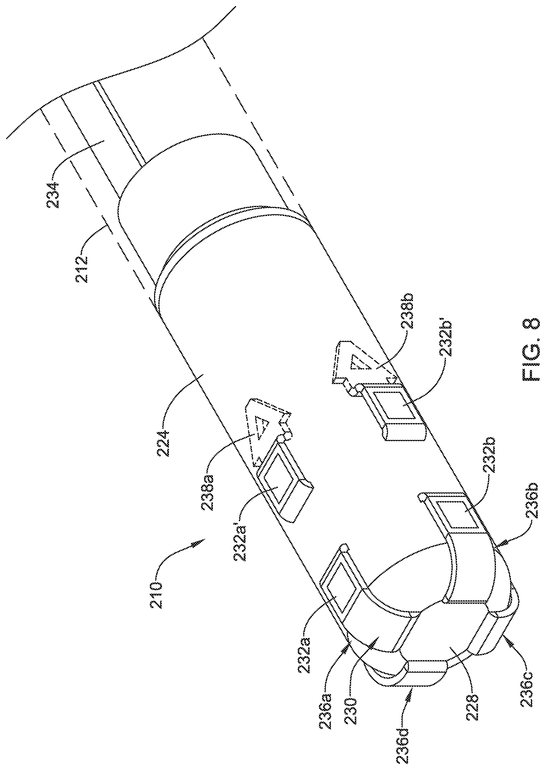
FIG. 7 illustrates another example electrode assembly 230 that may be similar in form and function to other assemblies disclosed herein and may be used, as appropriate, with the systems disclosed herein. Assembly 230 may include arms 236a/236b/236c/236d. Each of arms 236a/236b/236c/236d may include mechanical interconnecting member 138a/138b/138c/138d. In this example, two electrodes are defined along each of arms 236a/236b/236c/236d. For example, arm 236a may include electrodes 232a/232a', arm 236b may include electrodes 232b/232b', arm 236c may include electrodes 232c/232c', and arm 236d may include electrodes 232d/232d'.
FIG. 8 illustrates system 210. System 210 includes catheter shaft 212. Proximal connector 234 may be disposed along shaft 212 and may be coupled to electrode assembly 230. Electrode assembly 230 may be assembled onto distal ablation tip 224 in a manner similar to what is disclosed herein. For example, arms 236a/236b/236c/236d may be passed through port 228 and woven in and out of a pair of openings along distal ablation tip 224 so that electrodes 232a/232a'/232b/232b'/232c/232c'/232d/232d' are disposed along tip 224. Alternatively, each of arms 236a/236b/236c/236d may be passed through port 228, along the outer surface of distal ablation tip 224, and then through a single opening along distal ablation tip 224. In at least some instances, distal ablation tip 224 takes the form of a distal ablation tip electrode 224.
FIG. 9 illustrates another example electrode assembly 330 that may be similar in form and function to other assemblies disclosed herein and may be used, as appropriate, with the systems disclosed herein. In this embodiment, electrode assembly 330 may include three arms. For example, assembly 330 may include arms 336b/336c and a third arm/connector 334. Each of arms 336b/336c may include mechanical interconnecting member 338b/338c. Each of arms 336b/336c may include electrodes 332b/332c. Connector 334 may also include electrode 332a.
FIG. 10 illustrates system 310. System 310 includes catheter shaft 312. Electrode assembly 330 may be assembled onto distal ablation tip 324 in a manner similar to what is disclosed herein. For example, each of arms 336b/236c and connector 334 may be passed through port 328 and passed through an opening along distal ablation tip 324 so that electrodes 332a/332b/332c are disposed along tip 324. Connector 334 may continue along an inner surface (or an outer surface) of shaft 312 to a location where it may be coupled to a suitable processor/generator. In at least some instances, distal ablation tip 324 takes the form of a distal ablation tip electrode 324.
FIG. 11 illustrates another example electrode assembly 430 that may be similar in form and function to other assemblies disclosed herein and may be used, as appropriate, with the systems disclosed herein. Assembly 430 may include a plurality of electrodes 432. Assembly 430 may also include an opening 442 and proximal connector 434.
FIG. 12 illustrates system 410. System 410 includes catheter shaft 412. Electrode assembly 430 may be assembled onto distal ablation tip 424 in a manner similar to what is disclosed herein. For example, electrode assembly 430 may take the form of a strip that is designed to extend circumferentially about distal ablation tip 424. Proximal connector 434 may extend through opening 442 and then proximally along shaft 412. This may include extending proximal connector 434 along the outer surface of shaft 412, along the inner surface of shaft 412, or both. In at least some instances, distal ablation tip 424 takes the form of a distal ablation tip electrode 424.
FIG. 13 illustrates another example electrode assembly 530 that may be similar in form and function to other assemblies disclosed herein and may be used, as appropriate, with the systems disclosed herein. Assembly 530 may include a plurality of electrodes 532. Assembly 530 may also include a plurality of mechanical interconnecting member 538. In this example, a pair of opposing mechanical interconnecting members 538 are positioned on opposite sides of each electrode 532. Assembly 530 may also include proximal connector 534.
FIG. 14 illustrates system 510. System 510 includes catheter shaft 512. Electrode assembly 530 may be assembled onto distal ablation tip 524 in a manner similar to what is disclosed herein. For example, electrode assembly 530 may be disposed about distal ablation tip 524. Mechanical interconnecting members 538 may extend through openings in distal ablation tip 524 to secure electrode assembly 530 to system 510 (and/or distal ablation tip 524). In at least some instances, distal ablation tip 524 takes the form of a distal ablation tip electrode 524.
FIG. 15 illustrates another example electrode assembly 630 that may be similar in form and function to other assemblies disclosed herein and may be used, as appropriate, with the systems disclosed herein. Assembly 630 may include arms 636a/636b/636c/636d and proximal connector 634. Each of arms 636a/636b/636c/636d may include one or more electrodes such as electrodes 632a/632b/632c/632d. Assembly 630 may be rolled into a cylindrical configuration as shown in FIG. 16.
FIG. 17 illustrates system 610. System 610 includes catheter shaft 612. Electrode assembly 630 may be assembled along distal ablation tip 624 in a manner similar to what is disclosed herein. For example, electrode assembly 630 may be disposed within distal ablation tip 624. When assembled, arms 636a/636b/636c/636d extend through openings in distal ablation tip 624 and bow radially outward. This may be due to the application of a compressive force on electrode assembly 630 during the assembly process. Alternatively, an elastomeric gasket may be disposed within electrode assembly 630 in order to bias arms 636a/636b/636c/636d radially outward and/or seal the openings along distal ablation tip 624. The use of a gasket may allow the openings in distal ablation tip 624 to be sealed without the use of an adhesive. In addition, the use of a gasket may also allow for additional structures to be disposed along the interior of distal ablation tip 624. In some instances, the proximal and/or distal ends of assembly 630 may be secured to the inner surface of distal ablation tip 624. Although not expressly shown, system 610 may include one or more irrigation ports, for example along distal ablation tip 624. In at least some instances, distal ablation tip 624 takes the form of a distal ablation tip electrode 624.
The use of electrode assembly 630 may desirable for a number of reasons. For example, using electrode assembly 630 may allow for assembly of system 610 while reducing/minimizing the possibility of damaging iridium oxide sputtered electrodes and/or to the parylene coating (e.g., when electrode assembly 630 includes such structures). The length of electrode assembly 630 exposed along the outer surface of system 610 may also be reduced, which may reduce the likelihood of electrode assembly 630 catching during a procedure and also may reduce the amount of surface area along distal ablation tip 624 that may be covered.
While FIGS. 14-16 illustrate arms 636a/636b/636c/636d oriented in an axial direction, electrode assembly 630 may also be arranged so that arms 636a/636b/636c/636d extend circumferentially or otherwise in a direction that is substantially transverse to the longitudinal axis of electrode assembly 630.
FIG. 18 illustrates another example electrode assembly 730 that may be similar in form and function to other assemblies disclosed herein and may be used, as appropriate, with the systems disclosed herein. Assembly 730 may include arms 736a/736b/736c/736d. Each of arms 736a/736b/736c/736d may include one or more electrodes such as electrodes 732a/732b/732c/732d and mechanical interconnecting members 738a/738b/738c/738d. Assembly 730 may also include a pair of proximal connectors 734a/734b. Assembly 730 may be formed into a generally cylindrical configuration as shown in FIG. 19.
FIG. 20 illustrates system 710. System 710 includes catheter shaft 712. Electrode assembly 730 may be assembled along distal ablation tip 724 in a manner similar to what is disclosed herein. For example, mechanical interconnecting members 738a/738b/738c/738d may extend through openings in distal ablation tip 724 to secure assembly 730 to system 710 (and/or to distal ablation tip 724). In at least some instances, distal ablation tip 724 takes the form of a distal ablation tip electrode 724.
FIG. 21 illustrates another example electrode assembly 830 that may be similar in form and function to other assemblies disclosed herein and may be used, as appropriate, with the systems disclosed herein. Assembly 830 may include arm 836, mechanical interconnecting member 838, and proximal connector 834. FIG. 22 illustrates system 810. System 810 includes catheter shaft 812. Electrode assembly 830 may be assembled along distal ablation tip 824 in a manner similar to what is disclosed herein. For example, electrode assembly 830 may be wrapped circumferentially about distal ablation tip 824. Alternatively, electrode assembly 830 may be woven in and out of openings formed in distal ablation tip 824. In at least some instances, distal ablation tip 824 takes the form of a distal ablation tip electrode 824.
FIG. 23 illustrates another example electrode assembly 930 that may be similar in form and function to other assemblies disclosed herein and may be used, as appropriate, with the systems disclosed herein. Assembly 930 may include arms 936a/936b/936c/936d. Each of arms 936a/936b/936c/936d may include one or more electrodes such as electrodes 932a/932b/932c/932d and mechanical interconnecting members 938a/938b/938c/938d. Assembly 930 may also include proximal connector 934.
FIG. 24 illustrates system 910. System 910 includes catheter shaft 912. Electrode assembly 930 may be assembled along distal ablation tip 924 in a manner similar to what is disclosed herein. For example, mechanical interconnecting members 938a/938b/938c/938d may extend through openings in distal ablation tip 924 to secure assembly 930 to system 910 (and/or to distal ablation tip 924). In at least some instances, distal ablation tip 924 takes the form of a distal ablation tip electrode 924.
FIG. 25 illustrates another example electrode assembly 1030 that may be similar in form and function to other assemblies disclosed herein and may be used, as appropriate, with the systems disclosed herein. Assembly 1030 may include arm 1036 arranged in a cylindrical orientation. A plurality of electrodes 1032 may be disposed along arm 1036. Mechanical interconnecting member 1038 may be disposed on an end region of arm 1036. Assembly 1030 may also include proximal connector 1034.
FIG. 26 illustrates system 1010. System 1010 includes catheter shaft 1012. Electrode assembly 1030 may be assembled along distal ablation tip 1024 in a manner similar to what is disclosed herein. For example, mechanical interconnecting member 1038 may extend through openings in distal ablation tip 1024 to secure assembly 1030 to system 1010 (and/or to distal ablation tip 1024). In at least some instances, distal ablation tip 1024 takes the form of a distal ablation tip electrode 1024.
FIG. 27 is a side view of another example system 1110 that may be similar in form and function to other systems disclosed herein. System 1110 includes shaft 1112. One or more ring electrodes 1122 may be disposed along shaft 1112. Distal ablation tip 1124 may be disposed at the distal end of shaft 1112. Electrode assembly 1130 may be disposed along distal ablation tip 1124. For example, electrode assembly 1130 may be attached to distal ablation tip 1124 using an adhesive or other suitable attachment mechanism. In some embodiments, a single electrode assembly 1130 may be disposed along distal ablation tip 1124. In other embodiments, a plurality of electrode assemblies 1130 (e.g., 2-8 or more) may be disposed along distal ablation tip 1124. In at least some instances, distal ablation tip 1124 takes the form of a distal ablation tip electrode 1124. Each electrode assembly 1130 may be formed from a dielectric material disposed along distal ablation tip 1124 with a strip of electrode material (e.g., 300 series stainless steel, gold, platinum, copper, etc.) disposed along the dielectric material. Electrode assembly 1130 may have a width of about 0.01-0.04 inches (e.g., about 0.025 inches) and a length of about 1-5 millimeters (e.g., 3 mm or about 0.118 inches). These are just examples.
FIG. 28 is a cross-sectional view of a portion of system 1110. Here it can be seen that electrode assembly 1130 may include an inner insulating layer 1150 and an outer conductive layer or electrode regions 1132. In some of these and in other embodiments, electrode assembly 1130 may include a flexible circuit as disclosed herein.
While FIG. 28 shows that four electrode assemblies 1130 may be disposed about system 1110, this is not intended to be limiting. For example, FIG. 29 illustrates system 1220 that includes three electrode assemblies 1230 are disposed along distal ablation tip 1224. In at least some instances, distal ablation tip 1224 takes the form of a distal ablation tip electrode 1224. Similarly to electrode assemblies 1130, electrode assemblies 1230 may include inner insulating layer 1250 and outer conductive layer or electrode region 1232.
FIG. 30 is a side view of another example system 1310 that may be similar in form and function to other systems disclosed herein. System 1310 includes shaft 1312. One or more ring electrodes 1322 may be disposed along shaft 1312. Distal ablation tip 1324 may be disposed at the distal end of shaft 1312. Electrode assembly 1330 may be disposed along distal ablation tip 1324. Electrode assembly 1330 may include insulating layer 1350 and electrode region 1332. In this example, electrode region 1332 may take the form of a discrete electrode surrounded by insulating layer 1350. In at least some instances, distal ablation tip 1324 takes the form of a distal ablation tip electrode 1324.
FIG. 31 is a side view of another example system 1410 that may be similar in form and function to other systems disclosed herein. System 1410 includes shaft 1412. One or more ring electrodes 1422 may be disposed along shaft 1412. Distal ablation tip 1424 may be disposed at the distal end of shaft 1412. Electrode assembly 1430 may be disposed along distal ablation tip 1424. Electrode assembly 1430 may include insulating layer 1450 and a plurality of electrode regions 1432a/1432b. In at least some embodiments, electrode regions 1432a/1432b may be a pair of bipolar electrodes. In at least some instances, distal ablation tip 1424 takes the form of a distal ablation tip electrode 1424.
FIGS. 32-33 illustrate another example system 1510 that may be similar in form and function to other systems disclosed herein. System 1510 includes shaft 1512. One or more ring electrodes 1522 may be disposed along shaft 1512. Distal ablation tip 1524 may be disposed at the distal end of shaft 1512. In at least some instances, distal ablation tip 1524 takes the form of a distal ablation tip electrode 1524.
Electrode assembly 1530 may be disposed along distal ablation tip 1524. In this example, electrode assembly 1530 may extend to and/or along the distal end of distal ablation tip 1524 as can be seen in FIG. 33, which is an end view of system 1510. Here it can be seen that electrode assembly 1530 may include insulating layer 1550 and electrode region 1532.
FIG. 34 is a side view of another example system 1610 that may be similar in form and function to other systems disclosed herein. System 1610 includes shaft 1612. One or more ring electrodes 1622 may be disposed along shaft 1612. Distal ablation tip 1624 may be disposed at the distal end of shaft 1612. In at least some instances, distal ablation tip 1624 takes the form of a distal ablation tip electrode 1624.
Electrode assembly 1630 may be disposed along distal ablation tip 1624. Electrode assembly 1630 may include insulating layer 1650 and electrode region 1632.
FIG. 35 is an end view of another example system 1710 that may be similar in form and function to other systems disclosed herein. System 1710 includes distal ablation tip 1724. Electrode assembly 1730 may be disposed along distal ablation tip 1724. Electrode assembly 1730 may include insulating layer 1750 and electrode region 1732. In at least some instances, distal ablation tip 1724 takes the form of a distal ablation tip electrode 1724.
FIG. 36 is a side view of another example system 1810 that may be similar in form and function to other systems disclosed herein. System 1810 includes shaft 1812. One or more ring electrodes 1822 may be disposed along shaft 1812. Distal ablation tip 1824 may be disposed at the distal end of shaft 1812. In at least some instances, distal ablation tip 1824 takes the form of a distal ablation tip electrode 1824.
Electrode assembly 1830 may be disposed along distal ablation tip 1824. Electrode assembly 1830 may include a plurality of insulating layers 1850 and electrode region 1832 disposed between insulating layers 1850.
FIG. 37 is a side view of another example system 1910 that may be similar in form and function to other systems disclosed herein. System 1910 includes shaft 1912. One or more ring electrodes 1922 may be disposed along shaft 1912. Distal ablation tip 1924 may be disposed at the distal end of shaft 1912. In at least some instances, distal ablation tip 1924 takes the form of a distal ablation tip electrode 1924.
Electrode assembly 1930 may be disposed along distal ablation tip 1924. Electrode assembly 1930 may include a plurality of insulating layers 1950 and a plurality of electrode regions 1932a/1932b disposed between insulating layers 1950.
The materials that can be used for the various components of system 10 and/or other systems disclosed herein (e.g., shafts, micro-electrodes, distal ablation tip electrodes, flexible circuits, substrates, etc.) may include metals, metal alloys, polymers, metal-polymer composites, ceramics, combinations thereof, and the like, or other suitable material. Some examples of suitable polymers may include polytetrafluoroethylene (PTFE), ethylene tetrafluoroethylene (ETFE), fluorinated ethylene propylene (FEP), polyoxymethylene (POM, for example, DELRIN.RTM. available from DuPont), polyether block ester, polyurethane (for example, Polyurethane 85A), polypropylene (PP), polyvinylchloride (PVC), polyether-ester (for example, ARNITEL.RTM. available from DSM Engineering Plastics), ether or ester based copolymers (for example, butylene/poly(alkylene ether) phthalate and/or other polyester elastomers such as HYTREL.RTM. available from DuPont), polyamide (for example, DURETHAN.RTM. available from Bayer or CRISTAMID.RTM. available from Elf Atochem), elastomeric polyamides, block polyamide/ethers, polyether block amide (PEBA, for example available under the trade name PEBAX.RTM.), ethylene vinyl acetate copolymers (EVA), silicones, polyethylene (PE), Marlex high-density polyethylene, Marlex low-density polyethylene, linear low density polyethylene (for example REXELL.RTM.), polyester, polybutylene terephthalate (PBT), polyethylene terephthalate (PET), polytrimethylene terephthalate, polyethylene naphthalate (PEN), polyetheretherketone (PEEK), polyimide (PI), polyetherimide (PEI), polyphenylene sulfide (PPS), polyphenylene oxide (PPO), poly paraphenylene terephthalamide (for example, KEVLAR.R
D00000
D00001
D00002
D00003
D00004
D00005
D00006
D00007
D00008
D00009
D00010
D00011
D00012

D00013

D00014

D00015

D00016

D00017

D00018

D00019

D00020

D00021

D00022
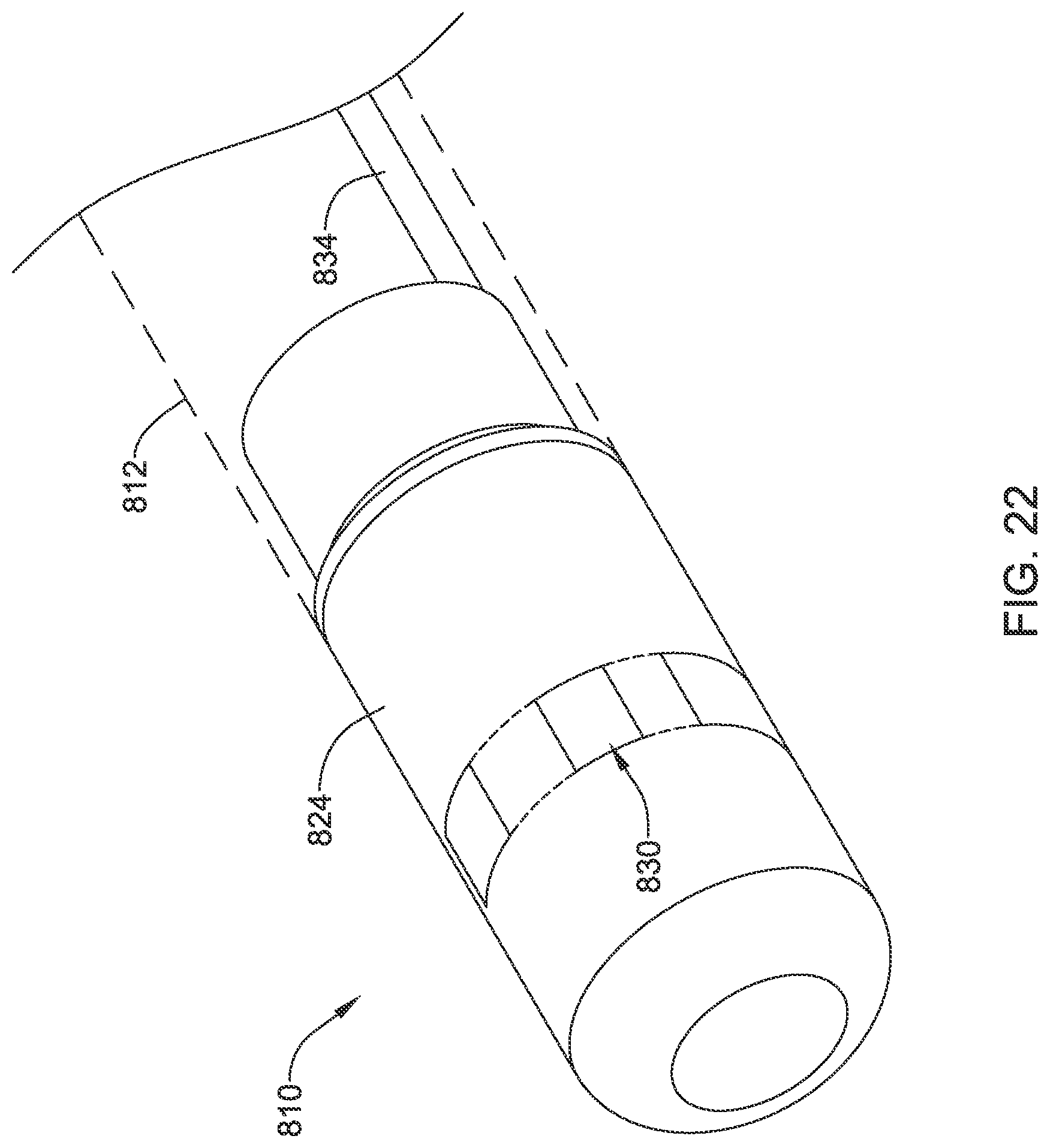
D00023

D00024

D00025

D00026
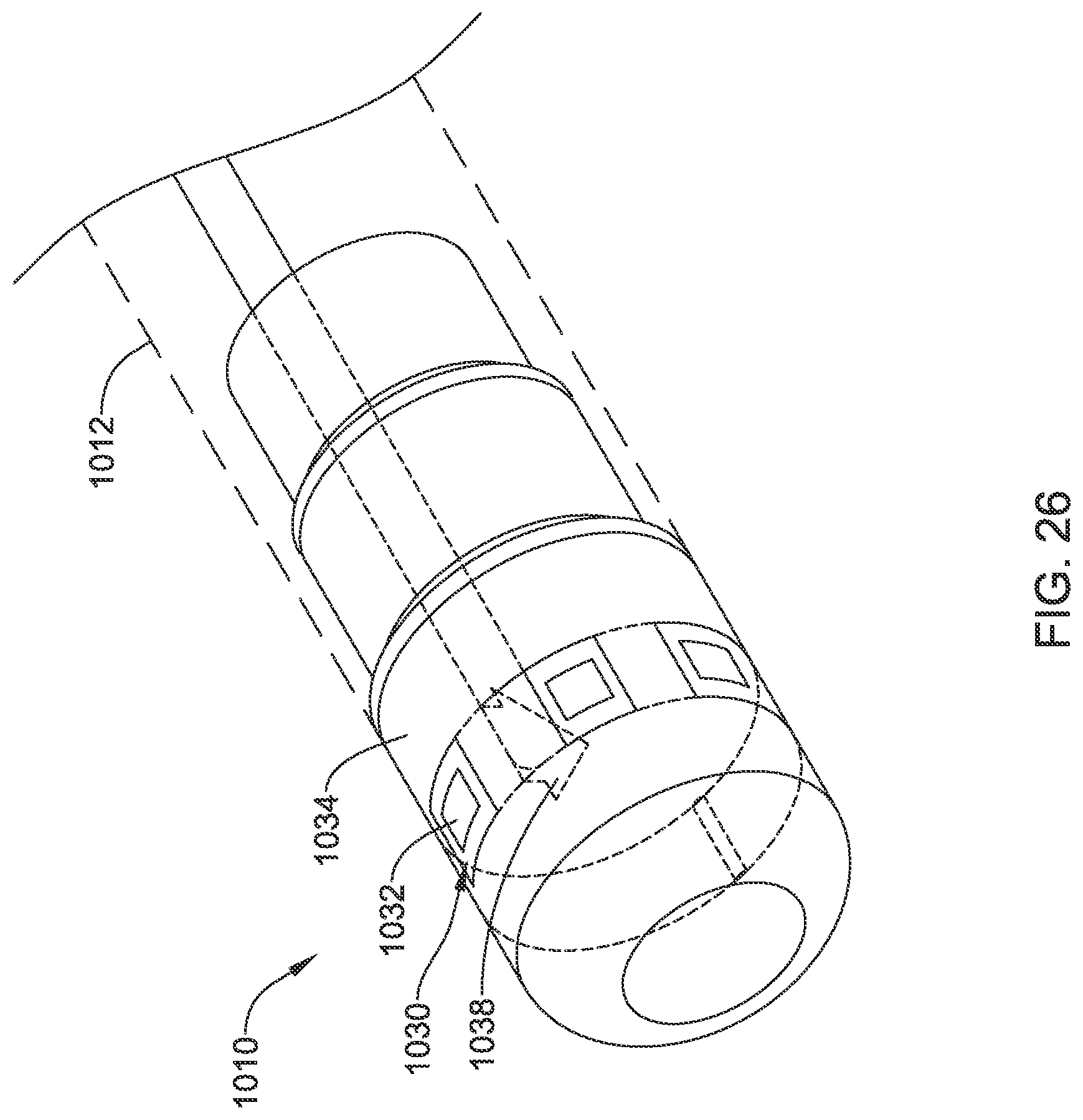
D00027

D00028

D00029

D00030

D00031

D00032

D00033

D00034

D00035

D00036

D00037

XML
uspto.report is an independent third-party trademark research tool that is not affiliated, endorsed, or sponsored by the United States Patent and Trademark Office (USPTO) or any other governmental organization. The information provided by uspto.report is based on publicly available data at the time of writing and is intended for informational purposes only.
While we strive to provide accurate and up-to-date information, we do not guarantee the accuracy, completeness, reliability, or suitability of the information displayed on this site. The use of this site is at your own risk. Any reliance you place on such information is therefore strictly at your own risk.
All official trademark data, including owner information, should be verified by visiting the official USPTO website at www.uspto.gov. This site is not intended to replace professional legal advice and should not be used as a substitute for consulting with a legal professional who is knowledgeable about trademark law.