Electric double layer capacitance device
Feaver , et al.
U.S. patent number 10,600,581 [Application Number 16/163,415] was granted by the patent office on 2020-03-24 for electric double layer capacitance device. This patent grant is currently assigned to BASF SE, University of Washington. The grantee listed for this patent is BASF SE, University of Washington. Invention is credited to Guozhong Cao, Aaron M. Feaver.


View All Diagrams
| United States Patent | 10,600,581 |
| Feaver , et al. | March 24, 2020 |
Electric double layer capacitance device
Abstract
The present application is directed to electric double layer capacitance (EDLC) devices. In one aspect, the present application is directed to an electrode comprising an activated carbon cryogel having a tunable pore structure wherein: the surface area is at least 1500 m2/g as determined by nitrogen sorption at 77K and BET analysis; and the pore structure comprises a pore volume ranging from about 0.01 cc/g to about 0.25 cc/g for pores having a pore diameter of 0.6 to 1.0 nm. In another aspect, the present application is directed to an Electric Double Layer Capacitor (EDLC) device comprising an activated cryogel.
| Inventors: | Feaver; Aaron M. (Seattle, WA), Cao; Guozhong (Seattle, WA) | ||||||||||
|---|---|---|---|---|---|---|---|---|---|---|---|
| Applicant: |
|
||||||||||
| Assignee: | BASF SE (Ludwigshafen,
DE) University of Washington (Seattle, WA) |
||||||||||
| Family ID: | 39402491 | ||||||||||
| Appl. No.: | 16/163,415 | ||||||||||
| Filed: | October 17, 2018 |
Prior Publication Data
| Document Identifier | Publication Date | |
|---|---|---|
| US 20190287737 A1 | Sep 19, 2019 | |
Related U.S. Patent Documents
| Application Number | Filing Date | Patent Number | Issue Date | ||
|---|---|---|---|---|---|
| 14448853 | Jul 31, 2014 | 10141122 | |||
| 13898341 | Aug 5, 2014 | 8797717 | |||
| 12897969 | Jun 18, 2013 | 8467170 | |||
| 11941015 | Nov 16, 2010 | 7835136 | |||
| 60866007 | Nov 15, 2006 | ||||
| Current U.S. Class: | 1/1 |
| Current CPC Class: | H01G 11/32 (20130101); C01B 32/318 (20170801); H01G 11/24 (20130101); H01G 11/26 (20130101); H01G 11/34 (20130101); H01G 11/86 (20130101); H01G 11/30 (20130101); C01B 32/30 (20170801); H01G 11/84 (20130101); Y02E 60/13 (20130101); Y10T 428/249978 (20150401); Y02P 20/133 (20151101); Y10T 428/24998 (20150401) |
| Current International Class: | H01G 11/32 (20130101); H01G 11/24 (20130101); C01B 32/30 (20170101); H01G 11/26 (20130101); H01G 11/34 (20130101); H01G 11/84 (20130101) |
References Cited [Referenced By]
U.S. Patent Documents
| 3518123 | June 1970 | Katsoulis et al. |
| 3619428 | November 1971 | David |
| 3876505 | April 1975 | Stoneburner |
| 3892580 | July 1975 | Messing |
| 3977901 | August 1976 | Buzzelli |
| 4082694 | April 1978 | Wennerberg et al. |
| 4159913 | July 1979 | Birchall et al. |
| 4198382 | April 1980 | Matsui |
| 4543341 | September 1985 | Barringer et al. |
| 4580404 | April 1986 | Pez et al. |
| 4769197 | September 1988 | Kromrey |
| 4843015 | June 1989 | Grubbs, Jr. et al. |
| 4862328 | August 1989 | Morimoto et al. |
| 4873218 | October 1989 | Pekala |
| 4954469 | September 1990 | Robinson |
| 4997804 | March 1991 | Pekala |
| 4999330 | March 1991 | Bose et al. |
| 5061416 | October 1991 | Willkens et al. |
| 5093216 | March 1992 | Azuma et al. |
| 5260855 | November 1993 | Kaschmitter et al. |
| 5294498 | March 1994 | Omaru et al. |
| 5416056 | May 1995 | Baker |
| 5420168 | May 1995 | Mayer et al. |
| 5465603 | November 1995 | Anthony et al. |
| 5508341 | April 1996 | Mayer et al. |
| 5529971 | June 1996 | Kaschmitter et al. |
| 5614460 | March 1997 | Schwarz et al. |
| 5626637 | May 1997 | Baker |
| 5626977 | May 1997 | Mayer et al. |
| 5670571 | September 1997 | Gabrielson et al. |
| 5674642 | October 1997 | Le et al. |
| 5710092 | January 1998 | Baker |
| 5726118 | March 1998 | Ivey et al. |
| 5744258 | April 1998 | Bai et al. |
| 5789338 | August 1998 | Kaschmitter et al. |
| 5834138 | November 1998 | Yamada et al. |
| 5858486 | January 1999 | Metter et al. |
| 5882621 | March 1999 | Doddapaneni et al. |
| 5891822 | April 1999 | Oyama et al. |
| 5908896 | June 1999 | Mayer et al. |
| 5945084 | August 1999 | Droege |
| 5965483 | October 1999 | Baker et al. |
| 6006797 | December 1999 | Billow et al. |
| 6064560 | May 2000 | Hirahara et al. |
| 6069107 | May 2000 | Kuznetsov et al. |
| 6072693 | June 2000 | Tsushima et al. |
| 6096456 | August 2000 | Takeuchi et al. |
| 6117585 | September 2000 | Anani et al. |
| 6147213 | November 2000 | Poli et al. |
| 6153562 | November 2000 | Villar et al. |
| 6205016 | March 2001 | Niu |
| 6225257 | May 2001 | Putyera et al. |
| 6242127 | June 2001 | Paik et al. |
| 6309446 | October 2001 | Nakanoya et al. |
| 6310762 | October 2001 | Okamura et al. |
| 6339528 | January 2002 | Lee et al. |
| 6509119 | January 2003 | Kobayashi et al. |
| 6574092 | June 2003 | Sato et al. |
| 6592838 | July 2003 | Nomoto et al. |
| 6697249 | February 2004 | Maletin et al. |
| 6764667 | July 2004 | Steiner, III |
| 6815105 | November 2004 | Cooper et al. |
| 6865068 | March 2005 | Murakami et al. |
| 7245478 | July 2007 | Zhong et al. |
| 7419649 | September 2008 | Lundquist et al. |
| 7582902 | September 2009 | Tano et al. |
| 7626804 | December 2009 | Yoshio et al. |
| 7722991 | May 2010 | Zhang et al. |
| 7723262 | May 2010 | Feaver et al. |
| 7754178 | July 2010 | Tano et al. |
| 7785495 | August 2010 | Kikuchi et al. |
| 7816413 | October 2010 | Feaver et al. |
| 7835136 | November 2010 | Feaver et al. |
| 8158556 | April 2012 | Feaver et al. |
| 8293818 | October 2012 | Costantino et al. |
| 8329252 | December 2012 | Markavov et al. |
| 8361659 | January 2013 | Richard |
| 8404384 | March 2013 | Feaver et al. |
| 8411415 | April 2013 | Yoshinaga et al. |
| 8467170 | June 2013 | Feaver et al. |
| 8480930 | July 2013 | Suh et al. |
| 8482900 | July 2013 | Gadkaree et al. |
| 8580870 | November 2013 | Costantino et al. |
| 8654507 | February 2014 | Costantino et al. |
| 8691177 | April 2014 | Pfeifer et al. |
| 8709971 | April 2014 | Feaver et al. |
| 8797717 | August 2014 | Feaver et al. |
| 8906978 | December 2014 | Costantino et al. |
| 8916296 | December 2014 | Feaver et al. |
| 8999202 | April 2015 | Mulik et al. |
| 9067848 | June 2015 | Stadie et al. |
| 9112230 | August 2015 | Feaver et al. |
| 9133295 | September 2015 | Qureshi et al. |
| 9133337 | September 2015 | Ludvik et al. |
| 9136064 | September 2015 | Gadkaree et al. |
| 9186174 | November 2015 | Krishnan |
| 9269502 | February 2016 | Chang et al. |
| 9287556 | March 2016 | Neumann et al. |
| 9409777 | August 2016 | Geramita et al. |
| 9412523 | August 2016 | Costantino et al. |
| 9464162 | October 2016 | Kron et al. |
| 9580321 | February 2017 | Feaver et al. |
| 9680159 | June 2017 | Feaver et al. |
| 9714172 | July 2017 | Geramita et al. |
| 9985289 | May 2018 | Costantino et al. |
| 10141122 | November 2018 | Feaver et al. |
| 10147950 | December 2018 | Sakshaug et al. |
| 10195583 | February 2019 | Costantino et al. |
| 10287170 | May 2019 | Feaver et al. |
| 2001/0002086 | May 2001 | Webb |
| 2002/0031706 | March 2002 | Dasgupta et al. |
| 2002/0031710 | March 2002 | Kezuka et al. |
| 2002/0036885 | March 2002 | Lee et al. |
| 2002/0104474 | August 2002 | Wakamatsu et al. |
| 2002/0114126 | August 2002 | Hirahara et al. |
| 2002/0122985 | September 2002 | Sato et al. |
| 2002/0168314 | November 2002 | Roemmler |
| 2002/0172637 | November 2002 | Chesneau et al. |
| 2003/0012722 | January 2003 | Liu |
| 2003/0013606 | January 2003 | Hampden-Smith et al. |
| 2003/0064564 | April 2003 | Lin |
| 2003/0108785 | June 2003 | Wu et al. |
| 2003/0170548 | September 2003 | Otsuki et al. |
| 2004/0106040 | June 2004 | Fukuoka et al. |
| 2004/0132845 | July 2004 | Rhine et al. |
| 2004/0141963 | July 2004 | Umekawa et al. |
| 2004/0180264 | September 2004 | Honbo et al. |
| 2004/0241237 | December 2004 | Pirard et al. |
| 2004/0248730 | December 2004 | Kim et al. |
| 2004/0248790 | December 2004 | Hinuma et al. |
| 2005/0014643 | January 2005 | Lini et al. |
| 2005/0041370 | February 2005 | Wilk et al. |
| 2005/0058589 | March 2005 | Lundquist et al. |
| 2005/0058907 | March 2005 | Kurihara et al. |
| 2005/0079349 | April 2005 | Hampden-Smith et al. |
| 2005/0079359 | April 2005 | Fujita et al. |
| 2005/0135993 | June 2005 | Xu et al. |
| 2005/0153130 | July 2005 | Long et al. |
| 2005/0196336 | September 2005 | Chatterjee et al. |
| 2005/0221981 | October 2005 | Wagh et al. |
| 2005/0233195 | October 2005 | Arnold et al. |
| 2005/0250011 | November 2005 | Mitchell et al. |
| 2005/0266990 | December 2005 | Iwasaki et al. |
| 2005/0282062 | December 2005 | Manako et al. |
| 2006/0008408 | January 2006 | Ho Yoon et al. |
| 2006/0057355 | March 2006 | Suzuki et al. |
| 2006/0079587 | April 2006 | Albert et al. |
| 2006/0093915 | May 2006 | Lundquist et al. |
| 2006/0223965 | October 2006 | Trifu |
| 2006/0240979 | October 2006 | Hirahara et al. |
| 2007/0002523 | January 2007 | Ando |
| 2007/0008677 | January 2007 | Zhong et al. |
| 2007/0048605 | March 2007 | Pez et al. |
| 2007/0104981 | May 2007 | Lam et al. |
| 2007/0142222 | June 2007 | Erkey et al. |
| 2007/0166602 | July 2007 | Burchardt |
| 2008/0011986 | January 2008 | Yamakawa et al. |
| 2008/0044726 | February 2008 | Feng et al. |
| 2008/0112876 | May 2008 | Dailey |
| 2008/0132632 | June 2008 | Schiraldi et al. |
| 2008/0145757 | June 2008 | Mah et al. |
| 2008/0145761 | June 2008 | Petrat et al. |
| 2008/0201925 | August 2008 | Zhong et al. |
| 2008/0204973 | August 2008 | Zhong et al. |
| 2008/0206638 | August 2008 | Takahashi et al. |
| 2008/0241640 | October 2008 | Rajeshwar et al. |
| 2008/0268297 | October 2008 | Quayle et al. |
| 2008/0293911 | November 2008 | Qureshi et al. |
| 2008/0297981 | December 2008 | Endo et al. |
| 2008/0299456 | December 2008 | Shiga et al. |
| 2009/0035344 | February 2009 | Thomas et al. |
| 2009/0053594 | February 2009 | Johnson et al. |
| 2009/0097189 | April 2009 | Tasaki et al. |
| 2009/0104509 | April 2009 | Kwak et al. |
| 2009/0104530 | April 2009 | Shizuka et al. |
| 2009/0114544 | May 2009 | Rousseau et al. |
| 2009/0117466 | May 2009 | Zhamu et al. |
| 2009/0145482 | June 2009 | Mitzi et al. |
| 2009/0185327 | July 2009 | Seymour |
| 2009/0213529 | August 2009 | Gogotsi et al. |
| 2009/0286160 | November 2009 | Kozono et al. |
| 2009/0305131 | December 2009 | Kumar et al. |
| 2010/0008021 | January 2010 | Hu et al. |
| 2010/0047671 | February 2010 | Chiang et al. |
| 2010/0051881 | March 2010 | Ahn et al. |
| 2010/0092370 | April 2010 | Zhang et al. |
| 2010/0097741 | April 2010 | Zhong et al. |
| 2010/0098615 | April 2010 | Tennison et al. |
| 2010/0110613 | May 2010 | Zhong et al. |
| 2010/0288970 | November 2010 | Watanabe et al. |
| 2010/0310941 | December 2010 | Kumta et al. |
| 2010/0316907 | December 2010 | Yamamoto et al. |
| 2011/0111284 | May 2011 | Maeshima et al. |
| 2011/0177393 | July 2011 | Park et al. |
| 2011/0200848 | August 2011 | Chiang et al. |
| 2011/0281180 | November 2011 | Kim et al. |
| 2011/0287189 | November 2011 | Shembel et al. |
| 2012/0045685 | February 2012 | Seki et al. |
| 2012/0129049 | May 2012 | Rayner |
| 2012/0156567 | June 2012 | Ayme-Perrot et al. |
| 2012/0183856 | July 2012 | Cui et al. |
| 2012/0241691 | September 2012 | Soneda et al. |
| 2012/0251876 | October 2012 | Jagannathan |
| 2012/0264020 | October 2012 | Burton et al. |
| 2012/0305651 | December 2012 | Anderson et al. |
| 2012/0308870 | December 2012 | Okuda et al. |
| 2012/0321959 | December 2012 | Yushin et al. |
| 2013/0004841 | January 2013 | Thompkins et al. |
| 2013/0082213 | April 2013 | Duncan et al. |
| 2013/0169238 | July 2013 | Rojeski |
| 2013/0189575 | July 2013 | Anguchamy et al. |
| 2013/0244862 | September 2013 | Ivanovici et al. |
| 2013/0295462 | November 2013 | Atanassova et al. |
| 2013/0337334 | December 2013 | Tao et al. |
| 2013/0344391 | December 2013 | Yushin et al. |
| 2014/0038042 | February 2014 | Rios et al. |
| 2014/0170482 | June 2014 | Park et al. |
| 2014/0287317 | September 2014 | Tiquet et al. |
| 2014/0302396 | October 2014 | Lu et al. |
| 2014/0335410 | November 2014 | Loveridge et al. |
| 2015/0037249 | February 2015 | Fu |
| 2015/0162603 | June 2015 | Yushin et al. |
| 2015/0207148 | July 2015 | Kimura et al. |
| 2015/0238917 | August 2015 | Mulik et al. |
| 2015/0306570 | October 2015 | Mayes et al. |
| 2016/0039970 | February 2016 | Kron et al. |
| 2016/0043384 | February 2016 | Zhamu et al. |
| 2016/0104882 | April 2016 | Yushin et al. |
| 2016/0133394 | May 2016 | Sakshaug et al. |
| 2016/0344030 | November 2016 | Sakshaug et al. |
| 2016/0372750 | December 2016 | Chang et al. |
| 2017/0015559 | January 2017 | Costantino et al. |
| 2017/0152340 | June 2017 | Geramita et al. |
| 2017/0346084 | November 2017 | Sakshaug et al. |
| 2018/0097240 | April 2018 | Feaver et al. |
| 2018/0130609 | May 2018 | Feaver et al. |
| 2018/0294484 | October 2018 | Fredrick et al. |
| 2018/0331356 | November 2018 | Feaver et al. |
| 2019/0097222 | March 2019 | Feaver et al. |
| 2019/0103608 | April 2019 | Costantino et al. |
| 2019/0259546 | August 2019 | Kron et al. |
| 2019/0267622 | August 2019 | Sakshaug et al. |
| 2019/0280298 | September 2019 | Sakshaug et al. |
| 2176452 | Nov 1997 | CA | |||
| 1554102 | Dec 2004 | CN | |||
| 1762900 | Apr 2006 | CN | |||
| 1986401 | Jun 2007 | CN | |||
| 101194384 | Jun 2008 | CN | |||
| 101318648 | Dec 2008 | CN | |||
| 101604743 | Dec 2009 | CN | |||
| 101969120 | Feb 2011 | CN | |||
| 102482095 | May 2012 | CN | |||
| 102820455 | Dec 2012 | CN | |||
| 102834955 | Dec 2012 | CN | |||
| 103094528 | May 2013 | CN | |||
| 103746098 | Apr 2014 | CN | |||
| 104108698 | Oct 2014 | CN | |||
| 102509781 | Nov 2015 | CN | |||
| 10 2010 049 249 | Apr 2012 | DE | |||
| 0 649 815 | Apr 1995 | EP | |||
| 0 861 804 | Sep 1998 | EP | |||
| 1 049 116 | Nov 2000 | EP | |||
| 1 052 716 | Nov 2000 | EP | |||
| 1 115 130 | Jul 2001 | EP | |||
| 1 248 307 | Oct 2002 | EP | |||
| 1 514 859 | Mar 2005 | EP | |||
| 2 117 068 | Nov 2009 | EP | |||
| 2 983 186 | Feb 2016 | EP | |||
| 2-300222 | Dec 1990 | JP | |||
| 4-59806 | Feb 1992 | JP | |||
| 4-139174 | May 1992 | JP | |||
| 5-117493 | May 1993 | JP | |||
| 5-156121 | Jun 1993 | JP | |||
| 5-320955 | Dec 1993 | JP | |||
| 8-59919 | Mar 1996 | JP | |||
| 8-112539 | May 1996 | JP | |||
| 9-63905 | Mar 1997 | JP | |||
| 9-275042 | Oct 1997 | JP | |||
| 9-328308 | Dec 1997 | JP | |||
| 7-232908 | Apr 1998 | JP | |||
| 10-297912 | Nov 1998 | JP | |||
| 2001-89119 | Apr 2001 | JP | |||
| 2001-278609 | Oct 2001 | JP | |||
| 2002-532869 | Oct 2002 | JP | |||
| 2004-67498 | Mar 2004 | JP | |||
| 2004-514637 | May 2004 | JP | |||
| 2004-203715 | Jul 2004 | JP | |||
| 2004-221332 | Aug 2004 | JP | |||
| 2004-315283 | Nov 2004 | JP | |||
| 2005-93984 | Apr 2005 | JP | |||
| 2005-132696 | May 2005 | JP | |||
| 2005-136397 | May 2005 | JP | |||
| 2005-187320 | Jul 2005 | JP | |||
| 2006-160597 | Jun 2006 | JP | |||
| 2006-248848 | Sep 2006 | JP | |||
| 2006-264993 | Oct 2006 | JP | |||
| 2007-115749 | May 2007 | JP | |||
| 2008-7387 | Jan 2008 | JP | |||
| 2008-94925 | Apr 2008 | JP | |||
| 2009-259803 | Nov 2009 | JP | |||
| 2012-121796 | Jun 2012 | JP | |||
| 10-2004-0080010 | Sep 2004 | KR | |||
| 95/01165 | Jan 1995 | WO | |||
| 98/30496 | Jul 1998 | WO | |||
| 98/55238 | Dec 1998 | WO | |||
| 02/39468 | May 2002 | WO | |||
| 2004/087285 | Oct 2004 | WO | |||
| 2004/099073 | Nov 2004 | WO | |||
| 2004/110930 | Dec 2004 | WO | |||
| 2005/043653 | May 2005 | WO | |||
| 2005/103490 | Nov 2005 | WO | |||
| 2007/061761 | May 2007 | WO | |||
| 2008/047700 | Apr 2008 | WO | |||
| 2008/113133 | Sep 2008 | WO | |||
| 2009/032104 | Mar 2009 | WO | |||
| 2010/032782 | Mar 2010 | WO | |||
| 2010/059749 | May 2010 | WO | |||
| 2010/138760 | Dec 2010 | WO | |||
| 2011/002536 | Jan 2011 | WO | |||
| 2011/003033 | Jan 2011 | WO | |||
| 2012/045002 | Apr 2012 | WO | |||
| 2012/071916 | Jun 2012 | WO | |||
| 2012/092210 | Jul 2012 | WO | |||
| 2013/120009 | Aug 2013 | WO | |||
| 2013/120011 | Aug 2013 | WO | |||
| 2014/201275 | Dec 2014 | WO | |||
| 2019/147836 | Aug 2019 | WO | |||
Other References
|
Abanades et al., "Experimental Analysis of Direct Thermal Methane Cracking," International Journal ofHydrogen Energy 36(20):12877-12886, 2011. cited by applicant . Abraham et al., "A Polymer Electrolyte-Based Rechargeable Lithium/Oxygen Battery," J. Electrochem. Soc. 143(1):1-5, Jan. 1996. cited by applicant . Alcaniz-Monge et al., "Methane Storage in Activated Carbon Fibres," Carbon 35(2):291-297, 1997. cited by applicant . Anderegg, "Grading Aggregates: II--The Application of Mathematical Formulas to Mortars," Industrial and Engineering Chemistry 23(9): 1058-1064, 1931. cited by applicant . Andreasen et al., "Ueber die Beziehung zwischen Kornabstufung und Zwischenraum in Produkten aus losen Kornern (mit einigen Experimenten)," Kolloid-Zeitschrift 50(3):217-228, Mar. 1930, with translation of summary. (17 pages). cited by applicant . Babie et al., "Carbon cryogel as support of platinum nano-sized electrocatalyst for the hydrogen oxidation reaction," Electrochimica Acta 51:3820-3826, 2006. cited by applicant . Babi et al., "Characterization of carbon cryogel synthesized by sol-gel polycondensation and freeze-drying," Carbon 42:2617-2624, 2004. cited by applicant . Babi et al., "Characterization of carbon cryogels synthesized by sol-gel polycondensation," J. Serb. Chem. Soc. 70(1):21-31, 2005. cited by applicant . Barbieri et al., "Capacitance limits of high surface area activated carbons for double layer capacitors," Carbon 43:1303-1310, 2005. cited by applicant . Barton et al., "Tailored Porous Materials," Chem. Mater. 11:2633-2656, 1999. cited by applicant . Beattie et al., "High-Capacity Lithium-Air Cathodes," J. Electrochem. Soc. 156(1):A44-A47, 2009. cited by applicant . Besenhard, "Handbook of battery materials," Weinheim, Wiley-VCH, Weinheim, New York, 398-401, Dec. 31, 1999. cited by applicant . Bock et al., "Structural Investigation of Resorcinol Formaldehyde and Carbon Aerogels Using SAXS and BET," Journal of Porous Materials 4:287-294, 1997. cited by applicant . Buiel et al., "Li-insertion in hard carbon anode materials for Li-ion batteries," Electrochimica Acta 45:121-130, 1999. cited by applicant . Burchell et al., "Low Pressure Storage of Natural Gas for Vehicular Applications," The Engineering Society for Advancing Mobility Land Sea Air and Space, Government/Industry Meeting, Washington D.C., Jun. 19-21, 2000, 7 pages. cited by applicant . Butler et al., "Braking Performance Test Procedure for the Hybrid Vehicle Energy Storage Systems: Capacitor Test Results," Joint International Meeting of the Electrochemical Society, Abstract 684, Honolulu, HI, Oct. 3-8, 2004, 5 pages. cited by applicant . Cao et al., "Li-ion capacitors with carbon cathode and hard carbon/stabilized lithium metal powder anode electrodes," Journal of Power Sources 213:180-185, Apr. 2012. cited by applicant . Chang et al., "Carbon Materials Comprising Enhanced Electrochemical Properties," U.S. Appl. No. 14/988,625, filed Jan. 5, 2016, 112 pages. cited by applicant . Chmiola et al., "Anomalous Increase in Carbon Capacitance at Pore Sizes Less Than 1 Nanometer," Science 313:1760-1763, Sep. 22, 2006. cited by applicant . Constantino et al., "Carbon-Based Compositions With Highly Efficient Volumetric Gas Sorption," filed Nov. 5, 2014, U.S. Appl. No. 14/533,956, 90 pages. cited by applicant . Conway et al., "Partial Molal vols. Of Tetraalkylammonium Halides and Assignment of Individual Ionic Contributions," Trans. Faraday Soc. 62:2738-2749, 1966. cited by applicant . Costantino et al., "Enhanced Packing of Energy Storage Particles," U.S. Appl. No. 15/199,343, filed Jun. 30, 2016, 97 pages. cited by applicant . Czakkel et al., "Influence of drying on the morphology of resorcinol-formaldehyde-based carbon gels," Microporous and Mesoporous Materials 86:124-133, 2005. cited by applicant . Debart et al., ".alpha.-MnO2 Nanowires: A Catalyst for the O2 Electrode in Rechargeable Lithium Batteries," Agnew. Chem. Int. Ed. 47:4521-4524, 2008. cited by applicant . Ding et al., "How Conductivities and Viscosities of PC-DEC and PC-EC Solutions of LiBF4, LiPF6, LiBOB, Et4NBF4, and Et4NBF6 Differ and Why," Journal of the Electrochemical Society 151(12):A2007-A2015, 2004. cited by applicant . Dinger et al., "Particle Packing III--Discrete versus Continuous Particle Sizes," Interceram 41(5):332-334, 1992. cited by applicant . Dinger et al., "Particle Packing IV--Computer Modelling of Particle Packing Phenomena," Interceram 42(3):150-152, 1993. cited by applicant . Edward, "Molecular Volumes and the Stokes-Einstein Equation," Journal of Chemical Education 47(4):261-270, Apr. 1970. cited by applicant . Eikerling et al., "Optimized Structure of Nanoporous Carbon-Based Double-Layer Capacitors," Journal of the Electrochemical Society 152(1):E24-E33, 2005. cited by applicant . Endo et al., "Morphology and organic EDLC applications of chemically activated AR-resin-based carbons," Carbon 40:2613-2626, 2002. cited by applicant . Feaver et al., "Activated carbon cryogels for low pressure methane storage," Carbon 44:590-593, 2006. cited by applicant . Fotouhi et al., "A Low Cost, Disposable Cable-Shaped AI-Air Battery for Portable Biosensors," J. Micromech. Microeng. 26:055011, 2016. (8 pages). cited by applicant . Furnas, "Grading Aggregates I--Mathematical Relations for Beds of Broken Solids of Maximum Density," Industrial and Engineering Chemistry 23(9):1052-1058, 1931. cited by applicant . Gao et al., "Nitrogen-rich graphene from small molecules as high performance anode material," Nanotechnology 25:415402, 2014, 8 pages. cited by applicant . Gouerec et al., "Preparation and Modification of Polyacrylonitrile Microcellular Foam Films for Use as Electrodes in Supercapacitors," Journal of the Electrochemical Society 148(1):A94-A101, 2001. cited by applicant . Hahn et al., "A dilatometric study of the voltage limitation of carbonaceous electrodes in aprotic EDLC type electrolytes by charge-induced strain," Carbon 44:2523-2533, 2006. cited by applicant . Hasegawa et al., "Preparation of carbon gel microspheres containing silicon powder for lithium ion battery anodes," Carbon 42:2573-2579, 2004. cited by applicant . Hirscher et al., "Are carbon nanostructures an efficient hydrogen storage medium?" Journal of Alloys and Compounds 356-357:433-437, 2003. cited by applicant . Hong et al., "Hydrogen evolution inhibition with diethylenetriamine modification of activated carbon for a lead-acid battery," RSC Adv. 4:33574-33577, 2014. cited by applicant . Hsieh et al., "Synthesis of mesoporous carbon composite and its electric double-layer formation behavior," Microporous and Mesoporous Materials 93:232-239, 2006. cited by applicant . Hu et al., "Effects of electrolytes and electrochemical pretreatments on the capacitive characteristics of activated carbon fabrics for supercapacitors," Journal of Power Sources 125:299-308, 2004. cited by applicant . Huang et al., "Nitrogen-containing mesoporous carbons prepared from melamine formaldehyde resins with CaCl.sub.2 as a template," J. Colloid Interface Sci. 363(1):193-198, 2011. cited by applicant . Indo German Carbons Limited, "Activated Carbon," Apr. 2009, URL=http://www.igcl.com/php/activated_carbon.php, download date Nov. 29, 2018, 3 pages. cited by applicant . Inomata et al., "Natural gas storage in activated carbon pellets without a binder," Carbon 40:87-93, 2002. cited by applicant . Job et al., "Carbon aerogels, cryogels and xerogels: Influence of the drying method on the textural properties of porous carbon materials," Carbon 43:2481-2494, 2005. cited by applicant . Job et al., "Highly dispersed platinum catalysts prepared by impregnation of texture-tailored carbon xerogels," Journal of Catalysis 240:160-171, 2006. cited by applicant . Job et al., "Synthesis of transition metal-doped carbon xerogels by solubilization of metal salts in resorcinol-formaldehyde aqueous solution," Carbon 42:3217-3227, 2004. cited by applicant . Khomenko et al., "High-voltage asymmetric supercapacitors operating in aqueous electrolyte," Appl. Phys. A 82:567-573, 2006. cited by applicant . Kim et al., "Correlation between the capacitor performance and pore structure," Tanso 221:31-39, 2006. cited by applicant . Kim et al., "Adsorption of phenol and reactive dyes from aqueous solution on carbon cryogel microspheres with controlled porous structure," Microporous and Mesoporous Materials 96:191-196, 2006. cited by applicant . Kocklenberg et al., "Texture control of freeze-dried resorcinol-formaldehyde gels," Journal of Non-Crystalline Solids 225:8-13, 1998. cited by applicant . Konno et al., "Preparation of activated carbon having the structure derived from biomass by alkali activation with NaOH, and its application for electric double-layer capacitor," Tanso 231:2-7, 2008. cited by applicant . Kowalczyk et al., "Estimation of the pore-size distribution function from the nitrogen adsorption isotherm. Comparison of density functional theory and the method of Do and co-workers," Carbon 41:1113-1125, 2003. cited by applicant . Lozano-Castello et al., "Influence of pore structure and surface chemistry on electric double layer capacitance in non-aqueous electrolyte," Carbon 41:1765-1775, 2003. cited by applicant . Lozano-Castello et al., "Powdered Activated Carbons and Activated Carbon Fibers for Methane Storage: A Comparative Study," Energy & Fuels 16:1321-1328, 2002. cited by applicant . McEwen et al., "Nonaqueous Electrolytes and Novel Packaging Concepts for Electrochemical Capacitors," The 7th International Seminar on Double Layer capacitors and Similar Energy Storage Devices, Deerfield Beach, FL Dec. 8-10, 1997, 56 pages. cited by applicant . Miller, "Pulse Power Performance of Electrochemical Capacitors: Technical Status of Present Commercial Devices," Proceedings of the 8th International Seminar on Double Layer Capacitors and Similar Energy Storage Devices, Deerfield Beach, Florida, Dec. 7-9, 1998, 9 pages. cited by applicant . Naoi et al., "Second generation `nanohybrid supercapacitor`: Evolution of capacitive energy storage devices," Energy Environ. Sci. 5:9363-9373, 2012. cited by applicant . Nishihara et al., "Preparation of resorcinol--formaldehyde carbon cryogel microhoneycombs," Carbon 42:899-901, 2004. cited by applicant . Ogasawara et al., "Rechargeable LI2O2 Electrode for Lithium Batteries," Journal American Chemical Society 128(4):1390-1393, 2006. cited by applicant . Otowa et al., "Production and adsorption characteristics of MAXSORB: High-surface-area active carbon," Gas Separation and Purification 7(4):241-245, 1993. cited by applicant . Paakko, "Long and entangled native cellulose I nanofibers allow flexible aerogels and hierarchically porous templates for functionalities," Soft Matter 4:2492-2499, 2008. cited by applicant . Pekala et al., "Aerogels derived from multifunctional organic monomers," Journal of Non-Crystalline Solids 145:90-98, 1992. cited by applicant . Pekala et al., "Structure of Organic Aerogels. 1. Morphology and Scaling," Macromolecules 26:5487-5493, 1993. cited by applicant . Pekala, "Organic aerogels from the polycondensation of resorcinol with formaldehyde," Journal of Materials Science 24:3221-3227, 1989. cited by applicant . Perrin et al., "Methane Storage within Dry and Wet Active Carbons: A Comparative Study," Energy & Fuels 17:1283-1291, 2003. cited by applicant . Pimenta et al., "Studying disorder in graphite-based systems by Raman spectroscopy," Phys. Chem. Chem. Phys. 9:1276-1291, 2007. cited by applicant . Pojanavaraphan et al., "Prevulcanized natural rubber latex/clay aerogel nanocomposites," European Polymer Journal 44:1968-1977, 2008. cited by applicant . Qu et al., "Studies of activated carbons used in double-layer capacitors," Journal of Power Sources 74:99-107, 1998. cited by applicant . Ravikovitch et al., "Unified Approach to Pore Size Characterization of Microporous Carbonaceous Materials from N2, Ar, and CO2 Adsorption Isotherms," Langmuir 16:2311-2320, 2000. cited by applicant . Read, "Ether-Based Electrolytes for the Lithium/Oxygen Organic Electrolyte Battery," J. Electrochem. Soc. 153(1):A96-A100, 2006. cited by applicant . Read et al., "Oxygen Transport Properties of Organic Electrolytes and Performance of Lithium/Oxygen Battery," J. Electrochem. Soc. 150(10):A1351-A1356, 2003. cited by applicant . Read, "Characterization of the Lithium/Oxygen Organic Electrolyte Battery," J. Electrochemical Soc. 149(9):A1190-A1195, 2002. cited by applicant . Reichenauer et al., "Microporosity in carbon aerogels," Journal of Non-Crystalline Solids 225:210-214, 1998. cited by applicant . Salitra et al., "Carbon Electrodes for Double-Layer Capacitors I. Relations Between Ion and Pore Dimensions," Journal of the Electrochemical Society 147(7):2486-2493, 2000. cited by applicant . Setoyama et al., "Simulation Study on the Relationship Between a High Resolution .alpha.s-Plot and the Pore Size Distribution for Activated Carbon," Carbon 36(10):1459-1467, 1998. cited by applicant . Sigma Aldrich, "Triton X-100," Data Sheet, URL=https://www.sigmaaldrich.com/catalog/product/roche/11332481001?lang=e- n®ion=US, download date Feb. 21, 2019. cited by applicant . Simon et al., "Materials for electrochemical capacitors," Nature Materials 7:845-854, Nov. 2008. cited by applicant . Sivakkumar et al., "Evaluation of Lithium-ion capacitors assembled with pre-lithiated graphite anode and activated carbon cathode," Electrochimica Acta 65:280-287, Jan. 2012. cited by applicant . Takeuchi et al., "Removal of single component chlorinated hydrocarbon vapor by activated carbon of very high surface area," Separation and Purification Technology 15:79-90, 1999. cited by applicant . Tamon et al., "Influence of freeze-drying conditions on the mesoporosity of organic gels as carbon precursors," Carbon 38:1099-1105, 2000. cited by applicant . Tamon et al., "Preparation of mesoporous carbon by freeze drying," Carbon 37:2049-2055, 1999. cited by applicant . Thompkins et al., "Composite Carbon Materials Comprising Lithium Alloying Electrochemical Modifiers," U.S. Appl. No. 14/084,469, filed Nov. 19, 2013. (424 App). cited by applicant . Tonanon et al., "Influence of surfactants on porous properties of carbon cryogels prepared by sol-gel polycondensation of resorcinol and formaldehyde," Carbon 41:2981-2990, 2003. cited by applicant . Toyo Tanso Carbon Products, "Special Graphite and Compound Material Products," Toyo Tanso Co., Ltd. Catalog published 2008. cited by applicant . Toyo Tanso, "Graphite Applications," Toyo Tanso Co., Ltd. Catalog published 1998. (Machine Translation Attached). cited by applicant . Toyo Tanso, "Isotropic Graphite Engineering Data," Toyo Tanso Co., Ltd. Catalog published 1994. cited by applicant . Toyo Tanso, "Isotropic Graphite Technical Data," Toyo Tanso Co., Ltd. Catalog published 1997. cited by applicant . Ue, "Mobility and Ionic Association of Lithium and Quaternary Ammonium Salts in Propylene Carbonate and .gamma.-Butyrolactone," J. Electrochem. Soc. 141(12):3336-3342, Dec. 1994. cited by applicant . WebElements, "Lead: the essentials," attached as a PDF showing the webpage availability date as of Aug. 14, 2009 (via the Wayback Machine), web URL is http://www.webelements.com/lead/, pp. 1-3. cited by applicant . Wei et al., "A novel electrode material for electric double-layer capacitors," Journal of Power Sources 141:386-391, 2005. cited by applicant . Williford et al., "Air electrode design for sustained high power operation of Li/air batteries," Journal of Power Sources 194:1164-1170, 2009. cited by applicant . Wu et al., "Fabrication and nano-structure control of carbon aerogels via a microemulsion-templated sol-gel polymerization method," Carbon 44:675-681, 2006. cited by applicant . Xie et al., "Pore size control of Pitch-based activated carbon fibers by pyrolytic deposition of propylene," Applied Surface Science 250:152-160, 2005. cited by applicant . Xu et al., "Optimization of Nonaqueous Electrolytes for Primary Lithium/Air Batteries Operated in Ambient Environment," Journal of the Electrochemical Society 156(10):A773-A779, 2009. cited by applicant . Xu et al., "Synthesis of mesoporous carbon and its adsorption property to biomolecules," Microporous and Mesoporous Materials 115:461-468, 2008. cited by applicant . Yamamoto et al., "Porous properties of carbon gel microspheres as adsorbents for gas separation," Carbon 42:1671-1676, 2004. cited by applicant . Yamamoto et al., "Control of mesoporosity of carbon gels prepared by sol-gel polycondensation and freeze drying," Journal of Non-Crystalline Solids 288:46-55, 2001. cited by applicant . Yamamoto et al., "Preparation and characterization of carbon cryogel microspheres," Carbon 40:1345-1351, 2002. cited by applicant . Yang et al., "Preparation of highly microporous and mesoporous carbon from the mesophase pitch and its carbon foams with KOH," Carbon 42:1872-1875, 2004. cited by applicant . Zhang et al., "Discharge characteristic of non-aqueous electrolyte Li/O2 battery," Journal of Power Sources 195:1235-1240, 2010. cited by applicant . Zhao et al., "Highly-Ordered Mesoporous Carbon Nitride with Ultrahigh Surface Area and Pore Volume as a Superior Dehydrogenation Catalyst," Chem. Mater. 26(10):3151-3161, 2014. cited by applicant. |
Primary Examiner: Sinclair; David M
Attorney, Agent or Firm: Seed Intellectual Property Law Group LLP
Claims
What is claimed:
1. An electrode comprising a binder and activated carbon, wherein the activated carbon comprises: a surface area of greater than 1500 m.sup.2/g, as determined by nitrogen sorption at 77 K and BET analysis; and a pore structure comprising mesopores having a diameter ranging from 2.0 nm to 10.0 nm and a pore volume ranging from 0.01 cc/g to 0.25 cc/g for pores having a pore diameter of 0.6 nm to 1.0 nm, as determined from N.sub.2 sorption derived DFT, wherein the electrode has a specific capacitance of at least 100 F/g and a specific power of at least 25 W/g when each of the specific capacitance and specific power is measured in an electric double layer capacitor device comprising an electrolyte comprising equal volumes of propylene carbonate and dimethylcarbonate and further comprising 1.0 M tetraethylammonium tetrafluoroborate.
2. The electrode of claim 1, wherein the electrode is a component in a supercapacitor, an ultracapacitor, an electric double layer capacitor or a pseudo capacitor.
3. The electrode of claim 1, wherein the binder is selected from polytetrafluorethylene, perfluoroalkoxy polymer resin, fluorinated ethylene-propylene, polyethylenetetrafluoroethylene, polyvinylfluoride, polyethylenechlorotrifluoroethylene, polyvinylidene fluoride, polychlorotrifluoroethylene, and trifluoroethanol.
4. The electrode of claim 1, wherein the pore structure comprises: a pore volume ranging from 0.01 cc/g to 0.15 cc/g for pores having a diameter less than 0.6 nm; a pore volume ranging from 0.30 cc/g to 0.70 cc/g for pores having a diameter between 1.0 nm and 2.0 nm; a pore volume ranging from 0.15 cc/g to 0.70 cc/g for pores having a diameter between 2.0 nm and 4.0 nm; a pore volume ranging from 0.06 cc/g to 0.50 cc/g for pores having a diameter between 4.0 nm and 6.0 nm; and a pore volume ranging from 0.01 cc/g to 0.30 cc/g for pores having a diameter between 6.0 nm and 8.0 nm; and wherein the pore volumes are determined from N.sub.2 sorption derived DFT.
5. The electrode of claim 1, wherein the specific capacitance ranges from 100 F/g to 130 F/g.
6. The electrode of claim 1, wherein the specific power ranges from 25 W/g to 35 W/g.
7. The electrode of claim 1, wherein the activated carbon has a surface area greater than 2000 m.sup.2/g, as determined by nitrogen sorption at 77K and BET analysis.
8. An Electric Double Layer Capacitor (EDLC) device comprising: a) a positive electrode and a negative electrode, wherein each of the positive and the negative electrodes comprise activated carbon; b) an inert porous separator; and c) an electrolyte; wherein the positive electrode and the negative electrode are separated by the inert porous separator, and wherein the activated carbon comprises: a surface area of greater than 1500 m.sup.2/g, as determined by nitrogen sorption at 77 K and BET analysis; and a pore structure comprising mesopores having a diameter ranging from 2.0 nm to 10.0 nm and a pore volume ranging from 0.01 cc/g to 0.25 cc/g for pores having a pore diameter of 0.6 nm to 1.0 nm, as determined from N.sub.2 sorption derived DFT; and wherein each of the positive and negative electrodes independently has a specific capacitance of at least 100 F/g and a specific power of at least 25 W/g when each of the specific capacitance and specific power is measured in an electric double layer capacitor device comprising an electrolyte comprising propylene carbonate and dimethylcarbonate and further comprising tetraethylammonium tetrafluoroborate.
9. The EDLC device of claim 8, wherein the specific capacitance of each of the positive and negative electrodes is no more than 150 F/g.
10. The EDLC device of claim 8, wherein the specific capacitance of each of the positive and negative electrodes independently ranges from 100 F/g to 130 F/g.
11. The EDLC device of claim 8, wherein the specific power of each of the positive and negative electrodes independently ranges from 25 W/g to 35 W/g.
12. The EDLC device of claim 8, wherein each of the positive and negative electrodes independently has a specific energy of at least 25 J/g.
13. The EDLC device of claim 8, wherein each of the positive and negative electrodes independently has a specific energy ranging from 38 J/g to 45 J/g.
14. The EDLC device of claim 8, wherein the activated carbon has a surface area greater than 2000 m.sup.2/g as determined by nitrogen sorption at 77K and BET analysis.
15. The EDLC device of claim 8, wherein the pore structure comprises a pore volume ranging from 0.30 cc/g to 0.70 cc/g for pores having a diameter between 1.0 nm and 2.0 nm, as determined from N.sub.2 sorption derived DFT.
16. The EDLC device of claim 8, wherein the pore structure comprises a pore volume ranging from 0.15 cc/g to 0.70 cc/g for pores having a diameter between 2.0 nm and 4.0 nm, as determined from N.sub.2 sorption derived DFT.
17. The EDLC device of claim 8, wherein the pore structure comprises: a pore volume ranging from 0.01 cc/g to 0.15 cc/g for pores having a diameter less than 0.6 nm; a pore volume ranging from 0.30 cc/g to 0.70 cc/g for pores having a diameter between 1.0 nm and 2.0 nm; a pore volume ranging from 0.15 cc/g to 0.70 cc/g for pores having a diameter between 2.0 nm and 4.0 nm; a pore volume ranging from 0.06 cc/g to 0.50 cc/g for pores having a diameter between 4.0 nm and 6.0 nm; and a pore volume ranging from 0.01 cc/g to 0.30 cc/g for pores having a diameter between 6.0 nm and 8.0 nm; and wherein the pore volumes are determined from N.sub.2 sorption derived DFT.
18. The EDLC device of claim 8, wherein the pore structure comprises mesopores having a diameter ranging from 2.0 nm to 4.0 nm, as determined from N.sub.2 sorption derived DFT.
19. The EDLC device of claim 8, wherein the pore structure comprises micropores having a diameter ranging from 0.3 nm to 2.0 nm, as determined from CO.sub.2 sorption derived DFT.
20. An electric double layer capacitor (EDLC) device comprising: a) a positive electrode and a negative electrode, wherein each of the positive and negative electrode comprises activated carbon and polytetrafluoroethylene; b) an inert porous separator comprising polypropylene, polyethylene or both; c) a first and a second current collector each comprising a non-corrosive metal; and d) an electrolyte comprising substantially equal volumes of propylene carbonate and dimethylcarbonate and further comprising about 1.0 M tetraethylammonium-tetrafluoroborate, wherein the positive and negative electrodes are separated by the porous separator and each is in contact with one current collector, and wherein the activated carbon comprises: a surface area of greater than 1500 m.sup.2/g, as determined by nitrogen sorption at 77 K and BET analysis; and a pore structure comprising mesopores having a diameter ranging from 2.0 nm to 10.0 nm and a pore volume ranging from 0.01 cc/g to 0.25 cc/g for pores having a pore diameter of 0.6 nm to 1.0 nm, as determined from N.sub.2 sorption derived DFT; and wherein each of the positive and negative electrodes independently has a specific capacitance of at least 100 F/g and a specific power of at least 25 W/g, as measured in the EDLC device.
21. The EDLC device of claim 20, wherein the specific capacitance of each of the positive and negative electrodes independently ranges from 100 F/g to 130 F/g.
22. The EDLC device of claim 20, wherein the specific power for each of the positive and negative electrodes independently ranges from 25 W/g to 35 W/g.
23. The EDLC device of claim 20, wherein each of the positive and negative electrodes independently has a specific energy ranging from 38 J/g to 45 J/g, as measured in the device.
24. The EDLC device of claim 20, wherein the activated carbon has a surface area greater than 2000 m.sup.2/g, as determined by nitrogen sorption at 77K and BET analysis.
Description
DETAILED DESCRIPTION
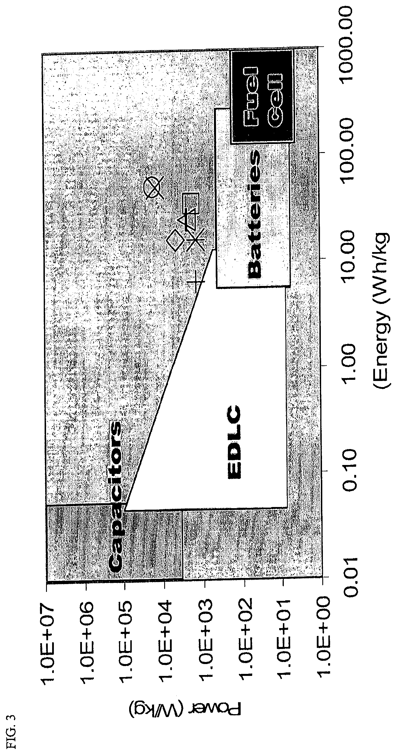
As hybrid vehicles become more ubiquitous, the need for enhancements in performance of electrical storage devices such as supercapacitors and batteries continues to grow. Electric Double Layer Capacitors (EDLCs) comprise one way to fill the gap between the high energy content of traditional electrochemical batteries or fuel cells and high power dielectric capacitors (see FIG. 3). However, current electrode materials in use generally result in an EDLC super capacitor that is a compromise both in terms of power and energy output. The new activated carbon cryogel electrode materials disclosed herein may bring super capacitors to a level that competes with the power of dielectric capacitors and the energy content of fuel cells or batteries. EDLCs store charge on the surface of the electrode material by adsorbing electrolyte ions in a charged double layer. For this reason, attention should be paid the surface area of the electrode as well as the accessibility of the pores and conductivity of the system once electrolyte is added. Examples of the activated carbon cryogel based electrodes presented herein display the ability to tune these parameters using simple sol-gel processing variables as well as using more standard modifications via pyrolysis and activation. These activated carbon cryogel electrodes can be prepared with surface areas higher than 2500 m.sup.2/g with tunable micropore size distribution that results in significant capacitance and power.
The present application is directed to electric double layer capacitance (EDLC) devices. In one aspect, the present application is directed to an electrode comprising an activated carbon cryogel having a tunable pore structure wherein: the surface area is at least 1500 m.sup.2/g as determined by nitrogen sorption at 77K and BET analysis; and the pore structure comprises a pore volume ranging from about 0.01 cc/g to about 0.25 cc/g for pores having a pore diameter of 0.6 to 1.0 nm. In another aspect, the present application is directed to an Electric Double Layer Capacitor (EDLC) device comprising an activated cryogel.
The embodiments of the invention and the various features and advantageous details thereof are explained more fully with reference to the non-limiting embodiments and examples that are described and/or illustrated in the accompanying drawings and detailed in the following description. It should be noted that the features of one embodiment may be employed with other embodiments as the skilled artisan would recognize, even if not explicitly stated herein. The examples used herein are intended merely to facilitate an understanding of ways in which the invention may be practiced and to further enable those of skill in the art to practice the embodiments of the present application. Accordingly, the examples and embodiments herein should not be construed as limiting the scope of the application, which is defined solely by the appended claims.
BRIEF DESCRIPTION OF THE FIGURES
FIG. 1 is a chronopotentiometry (CP) curve for a two cell electrode demonstrating how the values for V.sub.max, I, V, t, and ESR (in bold) are measured in order to determine capacitance, specific energy and power.
FIG. 2 is a drawing of a prototype capacitor cells constructed to test the electrode materials.
FIG. 3 is a graph of Energy (Wh/kg) vs. Power (W/g) in log 10 scale for activated carbon cryogels made with variations in R/C ratio and % activation as compared to performance regions for traditional dielectric capacitors, EDLCs currently in production, electrochemical batteries, and fuel cells.
FIG. 4A is a graph of R/C (resorcinol/catalyst ratio) of initial sol for activated carbon cryogels with activation at 70% vs. capacitance (F/g) and pore volume (cc/g).
FIG. 4B is a graph of R/C vs. capacitance and surface area (m.sup.2/g).
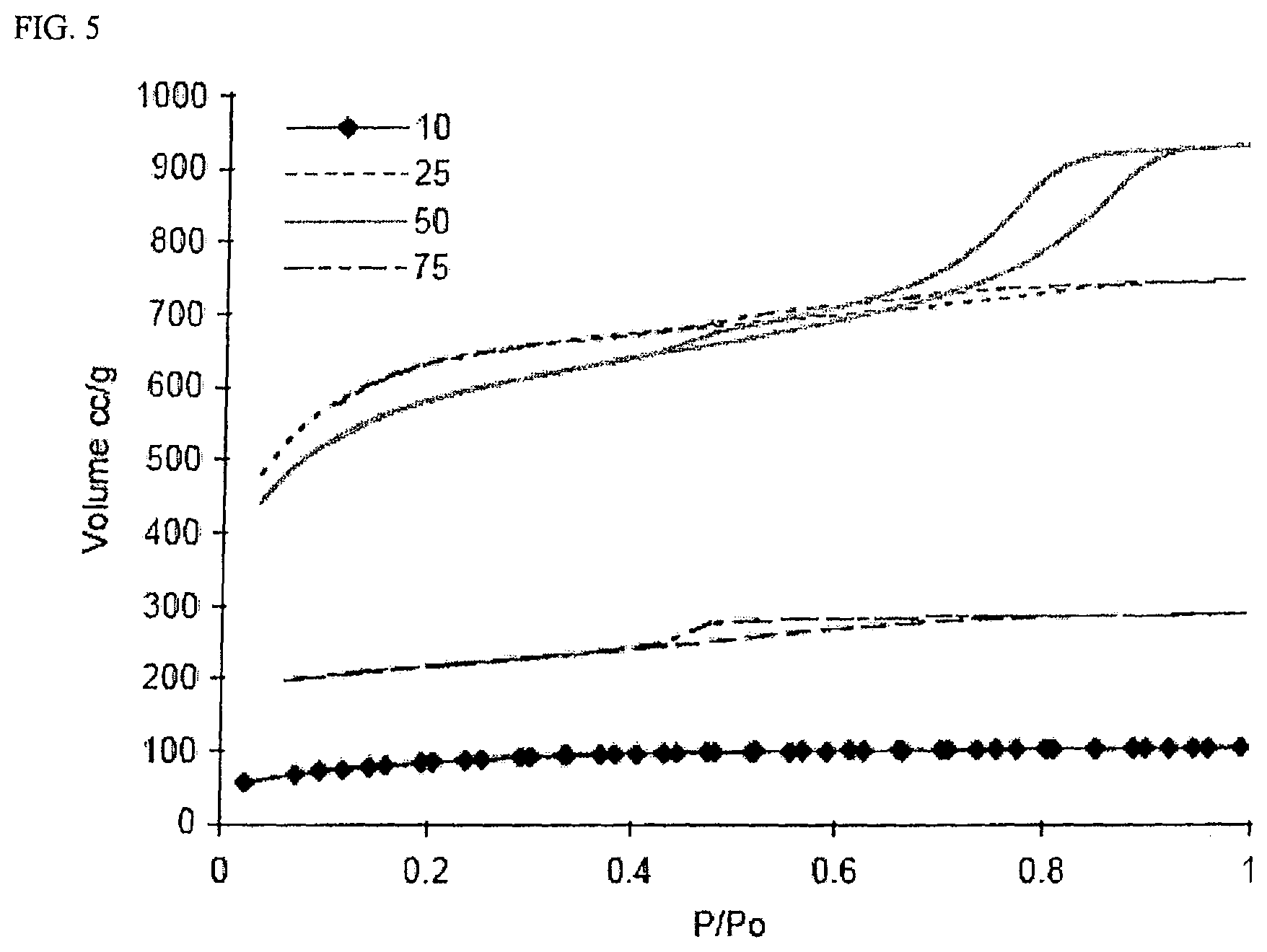
FIG. 5 is a graph of nitrogen sorption isotherms at 77 K for activated carbon cryogels made using R/C ratios of 10, 25, 50, and 75.
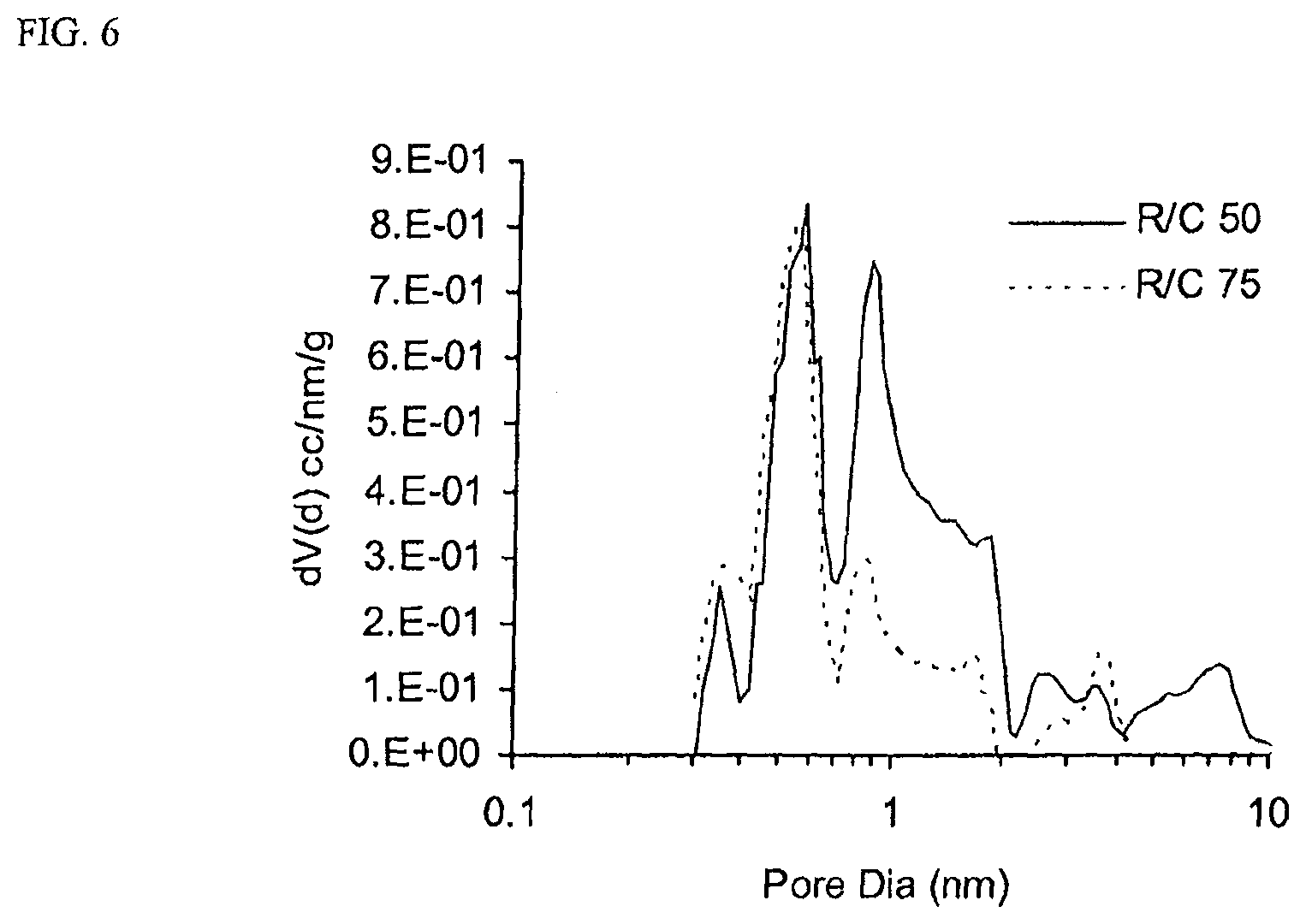
FIG. 6 is a pore size distribution for two samples with R/C ratio of 50 and 75 (all other parameters held equal).
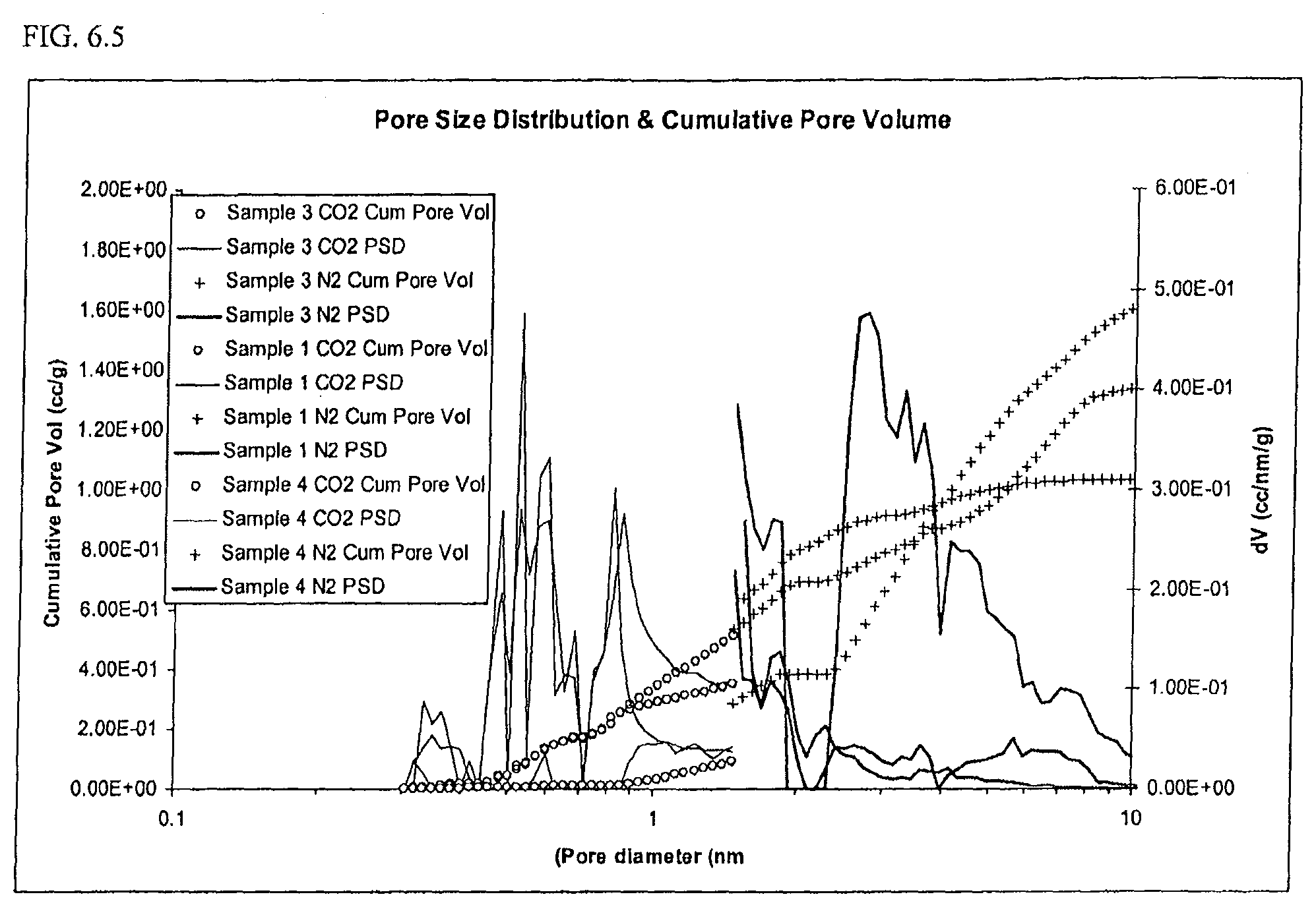
FIG. 6.5: Pore size distribution and cumulative pore volume from 0.35 nm-1.5 nm (using CO.sub.2 adsorption) and from 1.5. nm-10 nm (using N.sub.2 adsorption).
FIG. 7A is a graph of R/C vs. normalized values for pore size distribution in 4 ranges (<0.6 nm, 0.6-1.0 nm, 1.0-2.0 nm, 2.0-4.0 nm) as compared to capacitance. All values are multiplied by a constant such that the value at R/C=10 is forced to 1.00.
FIG. 7B is a graph of the same data as in FIG. 7A with Pore volume vs. Capacitance and capacitance vs. capacitance as a baseline.
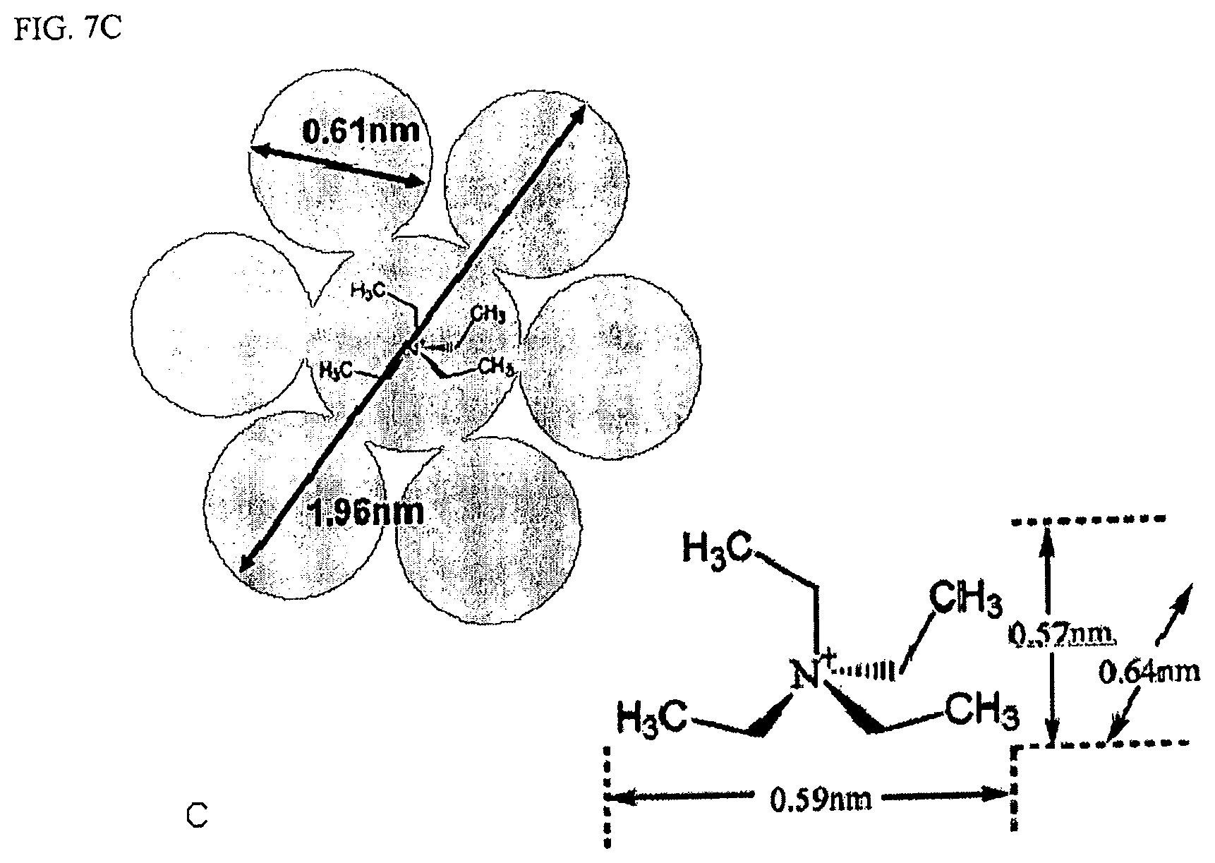
FIG. 7C are dimension diagrams of solvated TEA ion and unsolvated TEA ion.
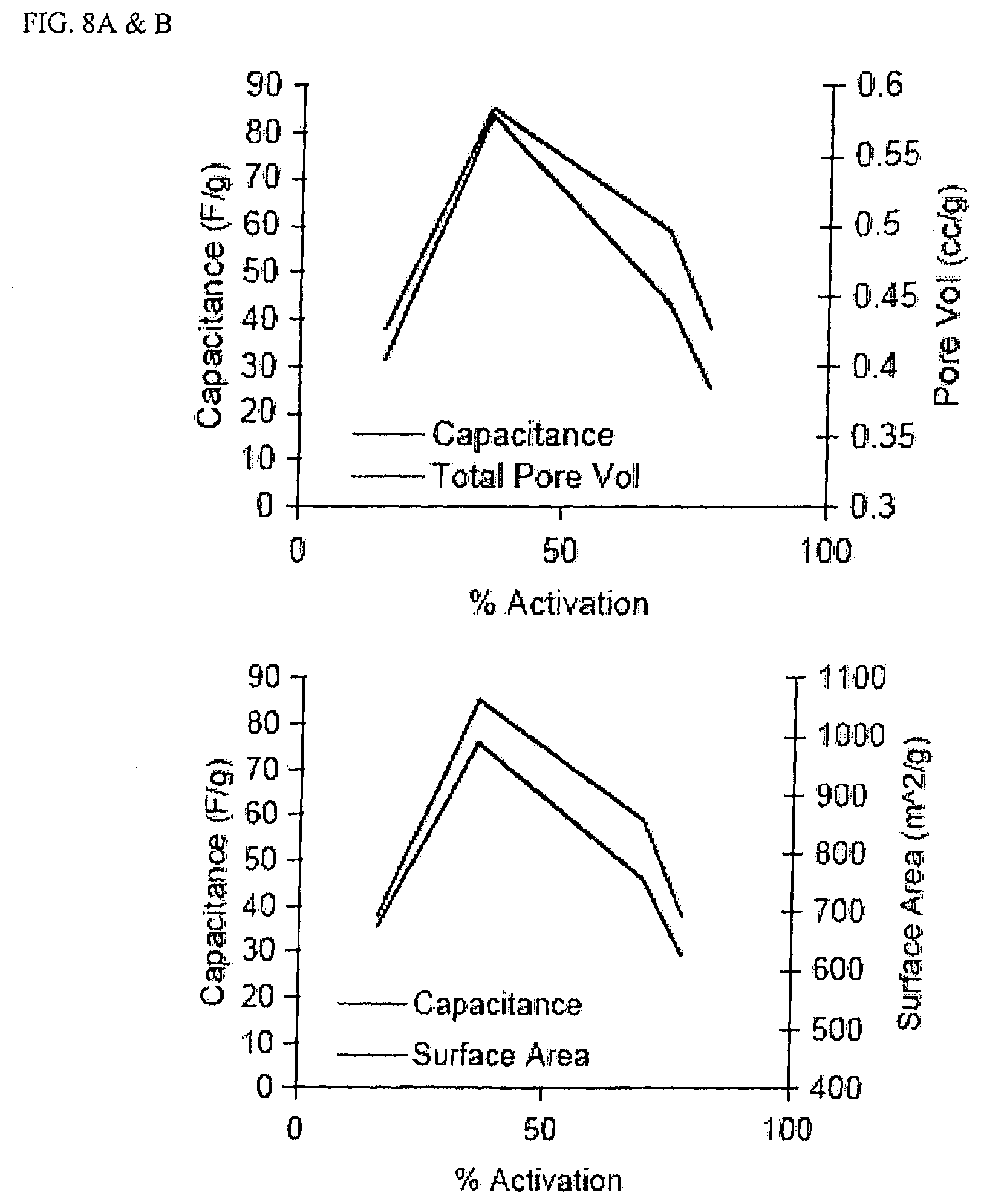
FIG. 8A is a graph of % Activation vs. capacitance (F/g) and pore volume (cc/g) for four samples activated to different levels.
FIG. 8B is a graph based on the same four samples with % activation plotted against capacitance and surface area (m.sup.2/g).
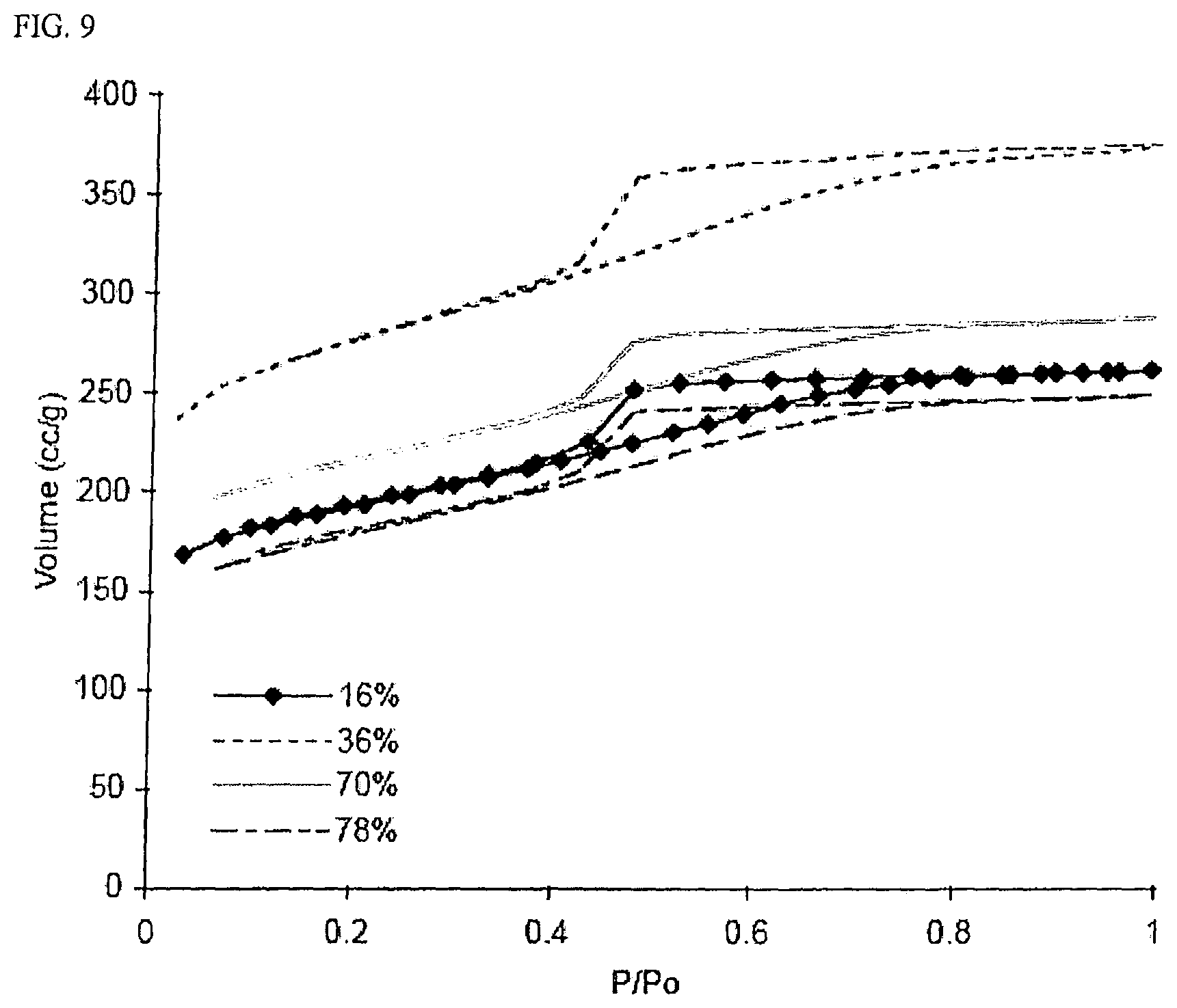
FIG. 9 is a graph of nitrogen sorption isotherms for four samples with the same R/C value activated to four different levels.
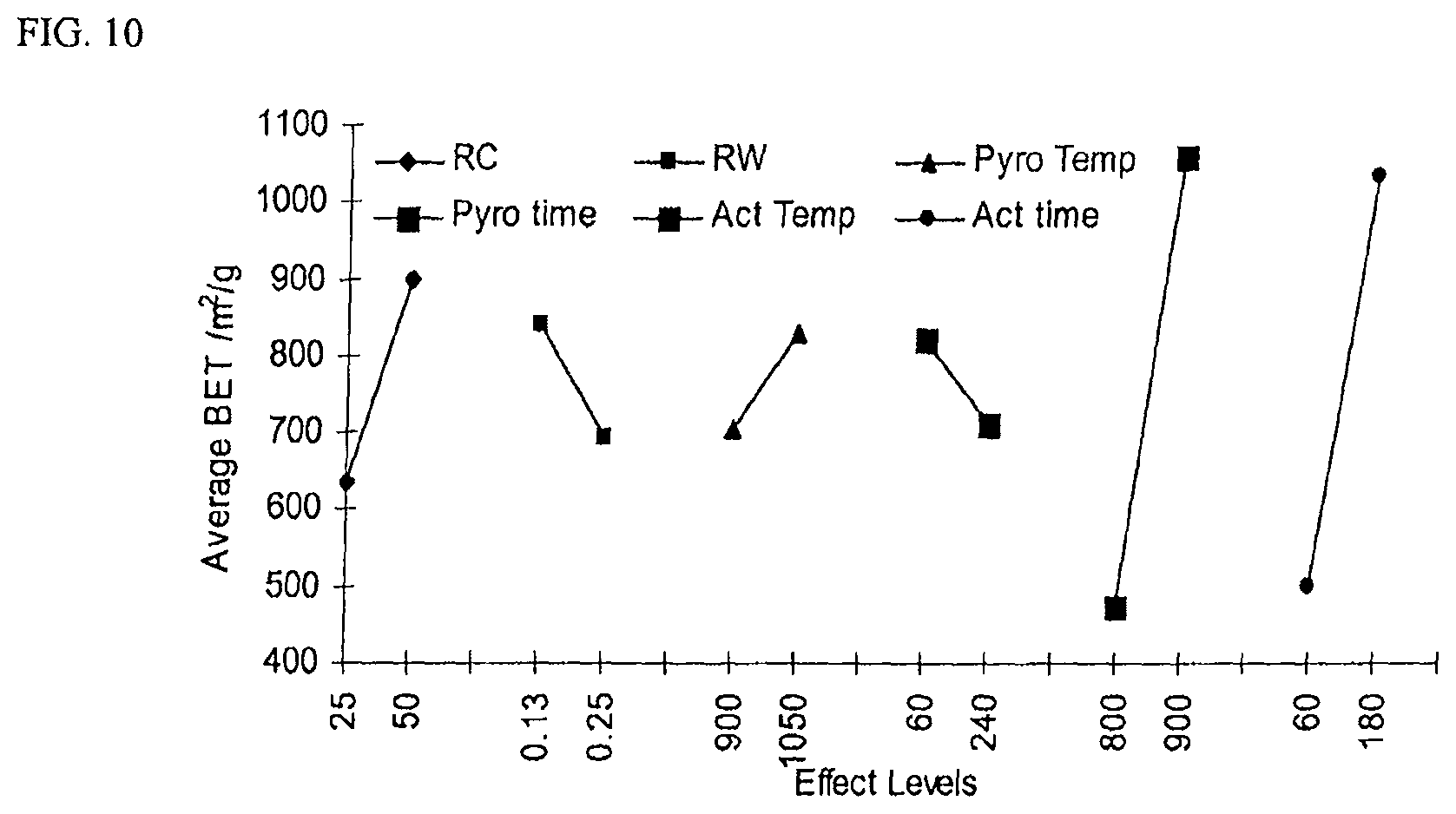
FIG. 10 is a Ybar marginal means plot with BET surface area as a response. High low values for each variable are shown on the x-axis and average BET surface area is shown on the y-axis.
FIG. 11A is a graph of the interaction for RC and RW for a sample of four interaction plots using the Taguchi L12 approach with BET surface area as a response.
FIG. 11B is a graph of the interaction for RW and activation temperature for a sample of four interaction plots using the Taguchi L12 approach with BET surface area as a response.
FIG. 11C is a graph of the interaction for pyrolysis time and RW for a sample of four interaction plots using the Taguchi L12 approach with BET surface area as a response.
FIG. 12 is a Ybar marginal means plots with responses for specific power; specific energy; and specific capacitance.
FIG. 13 is a complex plane representation of impedance data for a capacitor with porous electrodes.
FIGS. 14A-C provide the impedance data for sample 1. There is little voltage bias effect for this sample.
FIGS. 15A-C provide impedance data for sample 2. The effect of voltage for this sample was to move the complex plane line to the left which decreased the ESR. The shift in the complex plane plot probably is not significant and may be due to a small decrease in the electronic resistance.
FIG. 16 is a Ragone plot of experimentally determined energy-power relationship.
FIG. 17 is a graph of captured energy (left) and stored energy (right) on a mass basis by the four test capacitors. Voltage starts at 1.25 V and ends at 2.5 V during the charge. As charge times are decreased (higher charge rates), less of the energy is stored.
FIG. 18 is a ratio of energy stored to total available energy to store a different charge times (energy acceptance efficiency).
Unless specifically noted otherwise herein, the definitions of the terms used are standard definitions used in the art of organic and peptide synthesis and pharmaceutical sciences.
As used herein the term "electrode" refers to the porous material on which electrolyte ions are absorbed in order to form the double layer.
As used herein "synthetic polymer" refers to a polymer material derived from synthetic precursors or monomers.
As used herein the phrase "carbon cryogel," refers to an open porous structure derived from a polymer cryogel or other cryogel comprised of an organic material capable of yielding carbon, which is subsequently carbonized or pyrolyzed.
As used herein the term "sol" refers to a colloidal suspension of precursor particles and the term "gel" refers to a wet three-dimensional porous network obtained by condensation of the precursor particles.
As used herein the term "binder" refers to a material capable of holding individual particles of carbon together such that after mixing a binder and carbon together the resulting mixture can be formed into sheets, pellets or disks. Non-exclusive examples include fluoropolymers, such as, for example, PTFE (polytetrafluoroethylene, Teflon); PFA (perfluoroalkoxy polymer resin, also known as Teflon); FEP (fluorinated ethylene-propylene, also known as Teflon); ETFE (polyethylenetetrafluoroethylene, sold as Tefzel and Fluon); PVF (polyvinylfluoride, sold as Tedlar); ECTFE (polyethylenechlorotrifluoroethylene, sold as Halar); PVDF (polyvinylidene fluoride, sold as Kynar); PCTFE (polychlorotrifluoroethylene, sold as Kel-F and CTFE) and trifluoroethanol.
As used herein the term "inert" refers to a material that is not active in the electrolyte, that is it does not absorb a significant amount of ions or change chemically, e.g. degrade.
As used herein the term "porous separator" refers to a material that is capable of insulating the opposite electrodes from each other electrically but has open pores so that electrolyte can pass from one electrode to the other.
As used herein the term "conductive" refers to the ability of a material to conduct electrons through transmission of loosely held valence electrons.
As used herein the term "current collector" refers to a highly conductive material which is capable of conducting electrons much more easily than the active electrode material. Current collectors can comprise conductive polymers, metals, such as, for example, treated aluminum, stainless steel, titanium, platinum, gold, copper, nickel, or other such metals or combinations of metals and/or polymers that are not easily corroded by the electrolyte.
As used herein the term "electrical contact" refers to physical contact sufficient to conduct available current from one material to the next.
The term "pore" refers to an opening or depression in the surface, or a tunnel in a carbon based structure, i.e. a cryogel. A pore can be a single tunnel or connected to other tunnels in a continuous network throughout the structure.
As used herein the term "pore structure" refers to the layout of the surface of the internal pores within the activated carbon cryogel. Generally the pore structure of activated carbon cryogels comprises of micropores and mesopores. The term "mesopore" refers to pores having a diameter greater than 2 nanometers. The term "micropore" refers to pores having a diameter less than 2 nanometers.
As used herein the terms "activate," "activation," and "activated" each refer to any of the various processes by which the pore structure of a cryogel is enhanced. Generally, in such processes the microporosity inherent in the cryogel is exposed to the surface. Activation can be accomplished by use of, for example, steam, CO.sub.2 or chemicals. Activation in the presence of CO.sub.2(g) is specifically exemplified herein, but other activation methods are well-known to one of skill in the art. For example, chemical activation can employ activation aids, such as phosphoric acid, potassium hydroxide, sodium hydroxide, sodium carbonate, potassium carbonate, and zinc chloride.
The term "surface area" refers to the total surface area of a substance measurable by the BET technique.
As used herein "connected" when used in reference to mesopores and micropores refers to the spatial orientation of such pores such that electrolyte ions can pass freely from one pore to the next. As used herein "effective length" refers to the portion of the length of the pore that is of sufficient diameter such that it is available to accept salt ions from the electrolyte.
As used herein the term "synthetic polymer precursor material" refers to compounds used in the preparation of a synthetic polymer. Examples of precursor material that can be used in the preparation disclosed herein include, but are not limited to aldehydes, such as for example, methanal (formaldehyde); ethanal (acetaldehyde); propanal (propionaldehyde); butanal (butyraldehyde); glucose; benzaldehyde; cinnamaldehyde, as well as phenolic compounds that can be react with formaldehyde or other aldehydes in the presence of a basic catalyst to provide a polymeric gel (crosslinked gel). Suitable phenolic compounds include a polyhydroxy benzene, such as a dihydroxy or trihydroxy benzene. Representative polyhydroxy benzenes include resorcinol (i.e., 1,3-dihydroxy benzene), catechol, hydroquinone, and phloroglucinol. Mixtures of two or more polyhydroxy benzenes can also be used. Phenol (monohydroxy benzene) can also be used.
As used herein the term "tunable" refers to an ability to adjust the pore structure so that any one of pore size, pore volume, surface area, density, pore size distribution, and pore length of either or both of the mesopores and micropores are adjusted up or down. Tuning of the pore structure of the activated carbon cryogel can be accomplished a number of ways, including but not limited to varying the parameters of producing a tunable synthetic polymer precursor material; varying the parameters of freeze-drying the tunable synthetic polymer precursor material; varying the parameters of carbonizing the dried cryogel; and varying the parameters of activating the carbon cryogel.
As used herein, the terms "carbonizing" and "carbonization" each refer to the process of heating a carbon-containing substance in an inert atmosphere or in a vacuum so that the targeted material collected at the end of the process is primarily carbon.
As used herein "regen-capture energy captured" refers to the quantity of energy a device captures during charging; "regen-capture energy stored" refers to the fraction of the captured energy that is stored and then available to accelerate a vehicle when it proceeds after the stop.
As used herein "regen energy acceptance efficiency" refers to the ratio of energy that can be potentially stored to the energy that is actually stored.
As used herein in reference to the regen capture test, "regen time" refers to the time available to the EDLC device to charge. A non-limiting example of the charge includes, for example, 1.25V to 2.5V.
As used herein, "dwell temperature" refers to the temperature of the furnace during the portion of a process which is reserved for neither heating nor cooling, but maintaining a relatively constant temperature. So, for example, the carbonization dwell temperature refers to the relatively constant temperature of the furnace during carbonization and the activation dwell temperature refers to the relatively constant temperature of the furnace during activation. Generally the carbonization dwell temperature ranges from about 650.degree. C. to 1800.degree. C., alternately from about 800.degree. C. to about 900.degree. C. Generally the activation dwell temperature ranges from about 800.degree. C. to about 1300.degree. C. Alternately, the dwell temperature ranges from about 900.degree. C. to about 1050.degree. C.
Examples of an electrolyte appropriate for use in the devices of the present application include but are not limited to propylene carbonate, ethylene carbonate, butylene carbonate, dimethyl carbonate, methyl ethyl carbonate, diethyl carbonate, sulfolane, methylsulfolane and acetonitrile. Such solvents are generally mixed with solute, including, tetralkylammonium salts such as TEATFB (tetraethylammonium tetrafluoroborate); MTEATFB (methyltriethylammonium tetrafluoroborate); EMITFB (1-ethyl-3-methylimidazolium tetrafluoroborate) or triethylammonium based salts. Further the electrolyte can be a water based acid or base electrolyte such as mild sulfuric acid or potassium hydroxide.
Examples of catalyst useful in preparation of the activated carbon cryogel include but are not limited to sodium carbonate, ammonia, and sodium hydroxide. Generally, the catalyst can be any compound that facilitates the polymerization of the sol to form a sol-gel. In the case of the reaction between resorcinol and formaldehyde, sodium carbonate is usually employed. Generally such catalysts are used in the range of molar ratios of 10:1 to 2000:1 resorcinol:catalyst.
Examples of solvent useful in the preparation of the activated carbon cryogel comprising the devices of the present application include but are not limited to water or alcohol such as, for example, ethanol, t-butanol, methanol or mixtures of these, optionally further with water.
Examples of drying the tunable synthetic polymer precursor material include, but are not limited to freeze drying, air drying, or supercritical drying. The parameters for freeze drying, air drying, and supercritical drying are known to those of skill in the art.
The present application provides the following embodiments, aspects and variations:
One aspect of the present application is an electrode comprising an activated carbon cryogel having a tunable pore structure wherein: the surface area of the pore structure is at least 1500 m.sup.2/g as determined by nitrogen sorption at 77K and BET analysis; and the pore structure comprises a pore volume ranging from about 0.01 cc/g to about 0.25 cc/g for pores having a pore diameter of 0.6 to 1.0 nm. The carbon cryogel have a surface area and pores and pore structures. In one embodiment, the specific capacitance of the electrode is at least 75 F/g and the specific power of the electrode is at least 10 W/g when each of the specific capacitance and specific power is measured in a electric double layer capacitor device comprising an electrolyte comprising propylene carbonate. In another embodiment the electrode is a component in a supercapacitor, an electric double layer capacitor, an ultracapacitor, or a pseudo capacitor.
One aspect of the present application is an Electric Double Layer Capacitor (EDLC) device comprising a) a positive electrode and a negative electrode wherein each of the positive and the negative electrodes comprise an activated carbon cryogel having a tunable pore structure; b) an inert porous separator; c) an electrolyte; wherein the positive electrode and the negative electrode are separated by the inert porous separator; and the specific capacitance of each of the positive and negative electrodes is independently at least 75 F/g and the specific power of each of the positive and negative electrodes is independently at least 10 W/g. In one embodiment, each of the specific capacitance and the specific power is measured in the device comprising an electrolyte comprising equal volumes of propylene carbonate and dimethylcarbonate and further comprising about 1.0 M tetraethylammonium-tetrafluoroborate. In one embodiment, the specific capacitance of each of the positive and negative electrodes independently ranges from about 75 F/g to about 150 F/g; alternately, the specific capacitance of each of the positive and negative electrodes independently ranges from about 90 F/g to about 130 F/g. In another embodiment, the specific capacitance of each of the positive and negative electrodes independently ranges from about 100 F/g to about 130 F/g. In one variation, the specific capacitance of each of the positive and negative electrodes is at least about 75 F/g or about 80 F/g or about 85 F/g or about 80 F/g. In another variation, the specific capacitance of each of the positive and negative electrodes is no more than about 150 F/g, no more than about 145 F/g, no more than about 140 F/g, no more than about 135 F/g, or no more than about 130 F/g. In one variation of any of the aspects or embodiments disclosed herein, the specific capacitance of the positive electrode is equal to the specific capacitance of the negative electrode; alternately, the specific capacitance of the positive electrode is not equal to the specific capacitance of the negative electrode.
In another embodiment of any of the aspects disclosed herein the specific power of each of the positive and negative electrodes independently ranges from about 10 W/g to about 50 W/g, alternately, the specific power of each of the positive and negative electrodes independently ranges from about 25 W/g to about 35 W/g. In another embodiment of any of the aspects disclosed herein, the specific energy of each of the positive and negative electrodes independently is at least about 25 J/g; alternately, the specific energy of each of the positive and negative electrodes independently ranges from about 25 J/g to about 50 J/g. In another embodiment, the specific energy of each of the positive and negative electrodes independently ranges from about 38 J/g to about 45 J/g. In one variation, the specific power of each of the positive and negative electrodes independently is at least about 10 W/g, or 15 W/g or 20 W/g or 25 W/g. In another variation, the specific power of each of the positive and negative electrodes independently is no more than about 50 W/g, or 45 W/g or 40 W/g or 35 W/g.
In another embodiment of any of the aspects disclosed herein, the regen-capture energy stored by an EDLC device ranges from about 0.040 to about 0.055 kJ/g for a regen time of about 2.5 seconds. In yet another embodiment, the regen-capture energy stored by the device ranges from about 0.065 to about 0.075 kJ/g for a regen time of about 72 seconds. Alternately, the regen-capture energy stored by an EDLC device is about 0.048 kJ/g for a regen time of about 2.5 seconds and about 0.068 kJ/g for a regen time of about 72 seconds.
In another embodiment of any of the aspects disclosed herein, the regen-capture energy captured by an EDLC device ranges from about 0.050 to about 0.065 kJ/g for a regen time of about 2.5 seconds. In yet another embodiment, the regen-capture energy captured by the device ranges from about 0.070 to about 0.075 kJ/g for a regen time of about 72 seconds. Alternately, the regen-capture energy captured by the device is about 0.054 kJ/g for a regen time of about 2.5 seconds and about 0.072 kJ/g for a regen time of about 72 seconds.
In another embodiment of any of the aspects disclosed herein, the regen energy acceptance efficiency of an EDLC device ranges from about 0.85 to about 0.95 at 2.5 seconds. In yet another embodiment, the regen energy acceptance efficiency of the device ranges from about 0.95 to about 0.99 at 47 seconds. Alternately, the regen energy acceptance efficiency of the device is about 0.89 at 2.5 seconds and about 0.96 at 47 seconds.
In another embodiment of any of the aspects disclosed herein, the activated carbon cryogel has surface area greater than about 1500 m.sup.2/g as determined by nitrogen sorption at 77K and BET analysis. Alternately, the activated carbon cryogel has surface area greater than about 1800, or greater than about 2000 m.sup.2/g, or greater than about 2250 m.sup.2/g or greater than about 2500 m.sup.2/g or greater than about 2750 m.sup.2/g as determined by nitrogen sorption at 77K and BET analysis.
In another embodiment of any of the aspects disclosed herein, the EDLC device further comprises a binder. In one embodiment, the binder is selected from the group of fluoropolymers, such as polytetrafluoroethylene.
In another embodiment of any of the aspects disclosed herein, the electrolyte of the EDLC device is an aqueous or organic liquid electrolyte. In one variation, the electrolyte comprises acetonitrile. In another variation, the electrolyte is aqueous. In yet another variation, the electrolyte comprises an ammonium salt. In still another variation, the electrolyte comprises equal volumes of propylene carbonate and dimethylcarbonate and further comprises about 1.0 M tetraethylammonium-tetrafluoroborate. In yet another variation, the electrolyte is a solid state electrolyte.
In another embodiment of any of the aspects disclosed herein, the activated carbon cryogel is prepared according to a method comprising: a) combining in a first solvent a catalyst with a first monomeric polymer ingredient and a second monomeric polymer ingredient to yield a sol; b) gelling the sol by heating at a gelling temperature sufficient to yield a tunable synthetic polymer precursor material; c) freeze-drying the tunable synthetic polymer precursor material to yield a dried cryogel; and d) heating the dried cryogel in the presence of an inert gas or in a vacuum at a carbonization dwell temperature sufficient to carbonize the dried cryogel. e) heating the carbonized cryogel at an activation dwell temperature sufficient to activate the carbonized cryogel.
In one embodiment, the preparation of the activated carbon cryogel further comprises washing the tunable synthetic polymer precursor material with a second solvent to provide a solvent-exchanged tunable synthetic polymer precursor material. In one variation, the second solvent is an alcohol. In another embodiment, the second solvent is t-butanol.
In one embodiment, the activation of the carbonized cryogel is accomplished by any one of: i) heating the carbonized cryogel at an activation dwell temperature in the presence of carbon dioxide; ii) heating the carbonized cryogel at an activation dwell temperature in the presence of steam; iii) heating the carbonized cryogel at an activation dwell temperature in the presence of an activating aid.
In one variation, activation of the carbonized cryogel comprises heating the carbonized cryogel at an activation dwell temperature in the presence of carbon dioxide.
In another embodiment of any of the aspects disclosed herein, the tunable pore structure of the activated carbon cryogel is tuned by any one of: i) changing the catalyst; ii) changing the amount of catalyst; iii) changing the solvent used in step (a); iv) changing the amount of solvent; v) changing the first and/or second monomeric polymer ingredients; and vi) changing the relative amount of the first and/or second monomeric polymer ingredients. Such changes could thus lead to changes in the ratio of the first to second monomeric polymer ingredients, changes in the ratio of the first monomeric polymer ingredient to catalyst; changes in the ratio of the first monomeric polymer ingredient to solvent.
In one variation, the tunable pore structure of the activated carbon cryogel is tuned by any one of: i) changing the length of time of the freeze drying; ii) changing the pressure of the freeze drying; and iii) changing the temperature of the freeze drying.
In another variation, the tunable pore structure of the activated carbon cryogel is tuned by any one of: i) changing the dwell temperature at which the dried cryogel is carbonized; ii) changing the rate of heating to the carbonization dwell temperature; iii) changing the amount of time the dried cryogel is held at the carbonization dwell temperature; iv) using a different flow rate of gas during carbonization; v) using a different pressure of gas during carbonization; vi) using a different gas during carbonization; and vii) using a vacuum during carbonization.
In yet another variation, the tunable pore structure of the activated carbon cryogel is tuned by any one of: i) changing the dwell temperature at which the carbonized cryogel is activated; ii) changing the rate of heating to the activation dwell temperature; iii) changing the amount of time the dried cryogel is held at the activation dwell temperature; iv) using a different flow rate of gas during activation; v) using a different pressure of gas during activation; and vi) using a different gas during activation.
In one variation of any of the embodiments or aspects disclosed herein, the tunable pore structure of the activated cryogel has a pore volume ranging from about 0.01 cc/g to about 0.15 cc/g for pores having a diameter less than about 0.6 nm; alternately the tunable pore structure of the activated cryogel has a pore volume of about 0.12 cc/g for pores having a diameter less than about 0.6 nm. In another variation, the tunable pore structure has a pore volume ranging from about 0.01 cc/g to about 0.25 cc/g for pores having a diameter between about 0.6 nm and about 1.0 nm; alternately the tunable pore structure has a pore volume of about 0.19 cc/g for pores having a diameter between about 0.6 nm and about 1.0 nm. In yet another variation, the tunable pore structure has a pore volume ranging from about 0.30 cc/g to about 0.70 cc/g for pores having diameter between about 1.0 nm and about 2.0 nm; alternately the tunable pore structure has a pore volume of about 0.50 cc/g for pores having diameter between about 1.0 nm and about 2.0 nm. In another variation, the tunable pore structure has a pore volume ranging from about 0.15 cc/g to about 0.70 cc/g for pores having diameter between about 2.0 nm and about 4.0 nm; alternately the tunable pore structure has a pore volume of about 0.57 cc/g for pores having diameter between about 2.0 nm and about 4.0 nm. In yet a further variation, the tunable pore structure has a pore volume ranging from about 0.06 cc/g to about 0.50 cc/g for pores having diameter between about 4.0 nm and about 6.0 nm; alternately, the tunable pore structure has a pore volume of about 0.37 cc/g for pores having diameter between about 4.0 nm and about 6.0 nm. In still a further variation, the tunable pore structure has a pore volume ranging from about 0.01 cc/g to about 0.30 cc/g for pores having diameter between about 6.0 nm and about 8.0 nm; alternately the tunable pore structure has a pore volume of about 0.21 cc/g for pores having diameter between about 6.0 nm and about 8.0 nm.
In one variation of any of the embodiments or aspects disclosed herein, the tunable pore structure has a pore volume ranging from about 0.01 cc/g to about 0.15 cc/g for pores having a diameter less than about 0.6 nm; a pore volume ranging from about 0.01 cc/g to about 0.25 cc/g for pores having a diameter between about 0.6 nm and about 1.0 nm; a pore volume ranging from about 0.30 cc/g to about 0.70 cc/g for pores having diameter between about 1.0 nm and about 2.0 nm; a pore volume ranging from about 0.15 cc/g to about 0.70 cc/g for pores having diameter between about 2.0 nm and about 4.0 nm; a pore volume ranging from about 0.06 cc/g to about 0.50 cc/g for pores having diameter between about 4.0 nm and about 6.0 nm; and a pore volume ranging from about 0.01 cc/g to about 0.30 cc/g for pores having diameter between about 6.0 nm and about 8.0 nm.
In another variation of any of the embodiments or aspects disclosed herein, the tunable pore structure has a pore volume of about 0.12 cc/g for pores having diameter less than about 0.6 nm; a pore volume of about 0.19 cc/g for pores having diameter between about 0.6 nm and about 1.0 nm; a pore volume of about 0.35 cc/g for pores having diameter between about 1.0 nm and about 2.0 nm; a pore volume of about 0.19 cc/g for pores having diameter between about 2.0 nm and about 4.0 nm; a pore volume of about 0.20 cc/g for pores having diameter between about 4.0 nm and about 6.0 nm; and a pore volume of about 0.20 cc/g for pores having diameter between about 6.0 nm and about 8.0 nm.
In one embodiment of any of the aspects disclosed herein, the tunable pore structure of the activated cryogel comprises micropores having an effective length of less than about 10 nm as determined by TEM measurements. Alternately, it comprises micropores having an effective length of less than about 5 nm as determined by TEM measurements.
In one embodiment of any of the aspects disclosed herein, the tunable pore structure of the activated cryogel comprises mesopores having a diameter ranging from about 2.0 to about 10.0 nm as determined from N.sub.2 sorption derived DFT. The pore diameters disclosed herein in any embodiment or aspect can also be determined from N.sub.2 and CO.sub.2 sorption derived DFT. Alternately, the tunable pore structure comprises mesopores having a diameter ranging from about 2.0 to about 4.0 nm as determined from N.sub.2 sorption derived DFT or it comprises mesopores having a diameter ranging from about 3.0 to about 4.0 nm as determined from N.sub.2 sorption derived DFT. In another embodiment, the tunable pore structure of the activated cryogel comprises mesopores having a diameter ranging from about 4.0 to about 5.0 nm as determined from N.sub.2 sorption derived DFT.
In one embodiment of any of the aspects disclosed herein, the tunable pore structure of the activated cryogel comprises micropores having a diameter ranging from about 0.3 nm to about 2.0 nm as determined from CO.sub.2 sorption derived DFT. Alternately, the tunable pore structure comprises micropores having a diameter ranging from about 0.7 to about 1.5 nm as determined from CO.sub.2 sorption derived DFT. In another embodiment, the tunable pore structure comprises micropores having a diameter ranging from about 0.7 to about 1.0 nm as determined from CO.sub.2 sorption derived DFT or it comprises micropores having a diameter ranging from about 0.6 to about 1.0 nm as determined from CO.sub.2 sorption derived DFT.
One aspect of the present invention is an electric double layer capacitor (EDLC) device comprising: a) a positive electrode and a negative electrode wherein each of the positive and second electrode comprises an activated carbon cryogel and polytetrafluoroethylene; b) an inert porous separator comprising polypropylene or polyethylene; c) a first and a second current collector each comprising a non-corrosive metal; and d) an electrolyte comprising equal volumes of propylene carbonate and dimethylcarbonate and further comprising about 1.0 M tetraethylammonium-tetrafluoroborate; wherein the positive and negative electrodes are separated by the porous separator and each is in contact with one current collector; and the specific capacitance of each of the positive and negative electrodes as measured in the device is independently at least 75 F/g and the specific power of each of the positive and negative electrodes as measured using the device independently is at least 10 W/g.
In another embodiment, the activated carbon cryogel of the EDLC device is prepared according to a method comprising: a) combining in a solvent a catalyst with resorcinol and formaldehyde to yield a sol; b) gelling the sol by heating at a gelling temperature sufficient to yield a sol gel; c) freeze-drying the sol gel to yield a dried cryogel; and d) heating the dried cryogel in the presence of an inert gas at a carbonization dwell temperature sufficient to carbonize the dried cryogel; e) heating the carbonized cryogel at an activation dwell temperature sufficient to activate the carbonized cryogel.
One aspect of the present invention is a method of manufacturing an electrode comprising activated carbon cryogel comprising: a) carbonizing a cryogel; b) activating a carbonized cryogel; and c) combining an activated carbon cryogel with a fluoropolymer.
Another aspect of the present invention is a method of tuning the pore structure of an activated carbon cryogel of an electrode comprising changing at least one parameter chosen from: i) changing the catalyst used in preparation of the sol; ii) changing the amount of catalyst used in preparation of the sol; iii) changing the solvent used in preparation of the sol; iv) changing the amount of solvent used in preparation of the sol; v) changing the first and/or second monomeric polymer ingredients used in preparation of the sol; and vi) changing the relative amount of the first and/or second monomeric polymer ingredients used in preparation of the sol.
Another aspect of the present invention is a method of tuning the pore structure of an activated carbon cryogel of an electrode comprising changing at least one parameter chosen from: i) the dwell temperature at which the dried cryogel is carbonized; ii) the rate of heating to the carbonization dwell temperature; iii) the amount of time the dried cryogel is held at the carbonization dwell temperature; iv) the flow rate of gas during carbonization; iv) the pressure of gas during carbonization; vi) the gas during carbonization; vii) use of a vacuum during carbonization; viii) the dwell temperature at which the carbonized cryogel is activated; ix) the rate of heating to the activation dwell temperature; x) the amount of time the dried cryogel is held at the activation dwell temperature; iv) the flow rate of gas during activation; v) the pressure of gas during activation; and vi) the gas during activation.
In another aspect of the present application, the method of tuning the pore structure of an activated cryogel in an electric double layer capacitor comprises changing at least one parameter chosen from: i) the dwell temperature at which the dried cryogel is carbonized; ii) the rate of heating to the carbonization dwell temperature; iii) the amount of time the dried cryogel is held at the carbonization dwell temperature; iv) the flow rate of gas during carbonization; iv) the pressure of gas during carbonization; vi) the gas during carbonization; vii) use of a vacuum during carbonization; viii) the dwell temperature at which the carbonized cryogel is activated; ix) the rate of heating to the activation dwell temperature; x) the amount of time the dried cryogel is held at the activation dwell temperature; iv) the flow rate of gas during activation; v) the pressure of gas during activation; and vi) the gas during activation.
In one embodiment, the method of tuning the pore structure of an activated cryogel in an electric double layer capacitor comprises changing at least one parameter chosen from: i) the dwell temperature at which the dried cryogel is carbonized; ii) the rate of heating to the carbonization dwell temperature; iii) the amount of time the dried cryogel is held at the carbonization dwell temperature; iv) the flow rate of gas during carbonization; iv) the pressure of gas during carbonization; vi) the gas during carbonization; and vii) use of a vacuum during carbonization. Alternately, the method of tuning the pore structure of an activate cryogel in an electric double layer capacitor comprises changing at least one parameter chose from viii) the dwell temperature at which the carbonized cryogel is activated; ix) the rate of heating to the activation dwell temperature; x) the amount of time the dried cryogel is held at the activation dwell temperature; iv) the flow rate of gas during activation; v) the pressure of gas during activation; and vi) the gas during activation.
In one aspect of the present application, the device can also comprise a pseudo-capacitor, in which case both electrodes comprise either metal oxides or conductive polymers. The metal oxide can, for example, comprise ruthenium oxide, iridium oxide or nickel oxide, and the electrically conductive polymer can, for example, comprise polypyrrol, polythiophene or polyaniline, or derivatives of these conductive polymers. In the case of pseudo-capacitors, pseudo-capacitances develop on the surface of the electrodes as a result of the movement of electric charges generated by oxidation and reduction processes at the electrodes.
In one embodiment of any of the aspects disclosed herein, the EDLC device has a tunable pore structure comprising a) mesopores that are evenly dispersed throughout the structure; and b) micropores that: i) have an effective length of less than about 10 nm as determined by TEM measurements; and ii) are connected to the adjoining mesopores such that the micropores are accessible to the electrolyte ions.
In one aspect of the present application, a graph of the pore size distribution within the activated carbon cryogel does not contain narrow peaks, but instead indicates a range of pore sizes.
In another aspect of the present application, the majority of the micropores of the activated carbon cryogel have an effective length of less than 3 nm. In one embodiment, more than 50% of the micropores have an effective length of less than 3 nm; in another embodiment, more than 60%, or more than 70%, or more than 80%, or more than 90% of the micropores have an effective length of less than 3 nm.
EXAMPLES
Activated Carbon Cryogel Production and BET Analysis
The activated cryogels used in the super capacitor electrode materials are made from the standard chemicals: resorcinol {99+%, Sigma-Aldrich, C.sub.6H.sub.4(OH).sub.2}, formaldehyde solution {37%--stabilized with methanol (C.sub.2H.sub.5OH), Fisher Scientific, COH.sub.2}, sodium carbonate (99.5%, Sigma-Aldrich, NaCO.sub.3}, and tert-butyl-alcohol (t-butanol) {99.8%, J. T. Baker, (CH.sub.3).sub.3COH), and optionally trifluoroacetic acid {99%, Aldrich, C.sub.2HF.sub.3O.sub.2. These chemicals were used as received without further treatment. A series of activated carbon cryogels were fabricated. The molar ratio (R/F) of resorcinol (R) to formaldehyde (F) was maintained at 1:2 for all sols, while the molar ratio (R/C) of resorcinol to sodium carbonate catalyst (C) and the mass ratio (R/W) of resorcinol to water (W) were varied systematically. The sols were prepared by admixing resorcinol and formaldehyde in stirred distilled water followed by addition of catalyst at room temperature. The resulting sols were sealed in glass ampoules or vials and gelled at 90.degree. C. for at least 24 hours or until gelation was complete (as long as 7 days). The resulting resorcinol-formaldehyde (RF) hydrogels underwent solvent exchange to replace water with t-butanol by rinsing 3 times in fresh t-butanol for 24 hours each time, followed by subsequent freeze drying for 3 days. The resulting RF cryogels were pyrolyzed at 1050.degree. C. in N.sub.2 for 4 hours then activated at 900.degree. C. in CO.sub.2 with a flow rate of 400 SCCM (standard cubic centimeters per minute) for various durations. The pore structure was characterized by nitrogen sorption at 77 K and CO.sub.2 sorption at 273 K on a Quantachrome NOVA 4200e (Quantachrome Instruments, Boyton Beach, Fla.).
In one aspect of the present application, an acid rinse step using trifluoroacetic acid following gelation is included in the preparation of the activated carbon cryogel.
Electrochemical Analysis and Capacitance Measurements Using Cyclic Voltametry and Chronopotentiometry
Electrodes were prepared by mixing powdered activated carbon cryogel with 1%-3% by weight PTFE (polytetrafluoroethylene) binder. The mixture was rolled and then cut into discs 75 .mu.m thick and 9 mm in diameter.
The electrochemical test cell was made of a perfluoroalkoxy T-cell with stainless steel contacts. This cell has one advantage in that it mimics the conditions of a working capacitor and preserves the sample in an inert environment, such as for example, Argon. Symmetric carbon-carbon (C--C) capacitors were assembled in an Argon glove box. A porous polypropylene membrane (Celgard, by Celanese Plastics, Co., Ltd.) 25 .mu.m thick served as the separator. Once assembled, the samples were soaked in electrolyte for 20 minutes or more depending on the porosity of the sample. The electrolyte used was tetraethylammonium tetrafluoroborate (TEATFB) in saturated 50/50 propylene carbonate (PC)/dimethylcarbonate (DMC).
The capacitance and power output of the test cell was measured using cyclic voltametry (CV) and chronopotentiometry (CP) at various voltages (ranging from 1.0-3.5 maximum voltage) and current levels (from 1-10 mA) on an CHI electrochemical work station (CHI Instruments, USA). The capacitance (C) was calculated from the discharge curve of the potentiogram using the formula: C=i/s Equation 1 where i is the current (A) and s=V/t is the voltage rate in V/s. Since the test capacitor is a symmetric C--C electrode, the specific capacitance (C.sub.S in units of F/g)) was determined from: C.sub.s=2C/m.sub.e Equation 2 where m.sub.e is the mass of a single electrode. The specific energy (E.sub.s in units of W/g) and power (P.sub.s in units of J/g) were determined using:
.times..times..times..times..times..times. ##EQU00001## where C is the measured capacitance, V.sub.max is the maximum test voltage, and ESR is the equivalent series resistance obtained from the voltage drop at the beginning of the discharge. FIG. 1 shows how the values for i, s, V, t, Vmax, and ESR are calculated from the CP curve to determine values for the above equations.
Analogously, these equations can be used to calculate the specific capacitance, the specific energy, and the specific power of an electrode that is not a symmetric carbon-carbon electrode, as is exemplified herein.
Statistical Analysis
A Factorial Design of Experiments (DOE) was used to investigate the impact of each variable in the pore structure and performance of the activated cryogel in the electrode. Although DOE is not often used in this field of science, it was employed in this investigation to make use of the enormous amount of data generated by this effort at characterizing the impact of each different activated carbon cryogel processing parameter. The Taguchi L2 statistical design (from DOE Pro software from Digital Computations, Inc.) was used to evaluate the relative impact of each variable.
The samples were tested in two steps; in each, the variables investigated were: resorcinol/catalyst ratio (R/C), resorcinol/water ratio (R/W), the temperature and length of time of the pyrolysis of the RF cryogel, the temperature and length of time of the carbon dioxide activation. The first test employed a more typical design to find the optimal range for the RC ratio (one variable that influences the structure) as well as the ideal degrees of activation. This study then gave rise to a second test to evaluate the impact of R/C and activation each within an optimized range as well as fine tuning other variables within the best performing values of R/C and activation. Table 1 shows the processing parameters for the six different variables that were used in the Taguchi L12 design of experiments approach. By using this experimental plan and the DOE Pro software, Applicants identified the better of two high and low values while accounting for the first level interaction of multiple variables.
In the examples disclosed herein, all sol gel, and drying parameters were the same for all samples. Pyrolysis and activation parameters varied for Samples 1 to 4 as described below. Only R/C and % activation were used to modify the structure of the carbon. Particular details for the samples referenced herein are provided below:
Sample 1 (also referred to as "R/C 50") was prepared using an R/C of 50, an R/W of 0.25. N.sub.2 pyrolysis took place at 1050.degree. C. for 240 minutes. Activation took place at 900.degree. C. for a period of time necessary to achieve 70% activation
Sample 2 was prepared using an R/C of 50, an R/W of 0.125. N.sub.2 pyrolysis took place at 1050.degree. C. for 60 minutes. Activation took place at 900.degree. C. for a period of time necessary to achieve 45% activation.
Sample 3 (also referred to as "R/C 25") was prepared using an R/C of 25, an R/W of 0.25. N.sub.2 pyrolysis took place at 1050.degree. C. for 240 minutes. Activation took place at 900.degree. C. for a period of time necessary to achieve 70% activation.
Sample 4 was prepared using an R/C of 50, an R/W of 0.125. N.sub.2 pyrolysis took place at 1050.degree. C. for 60 minutes. Activation took place at 900.degree. C. for a period of time necessary to achieve 25% activation.
TABLE-US-00001 TABLE 1 Taguchi L12 experimental parameters used for finding the best processing conditions over 6 different variables: Sol-gel N.sub.2 Pyrolysis Parameters Temp CO.sub.2 Activation Row R/C R/W (.degree. C.) Time (min) Temp (.degree. C.) Time (min) 1 25 0.125 900 60 800 60 2 25 0.125 900 60 800 60 3 25 0.125 1050 240 900 180 4 25 0.25 900 240 800 180 5 25 0.25 1050 60 900 60 6 25 0.25 1050 240 900 180 7 50 0.125 1050 240 900 180 8 50 0.125 1050 60 900 60 9 50 0.125 900 240 800 180 10 50 0.25 1050 60 900 60 11 50 0.25 900 240 800 180 12 50 0.25 900 60 800 60
Electrochemical Analysis and Capacitance Measurements Using Impedance Spectroscopy Materials and Preparation
Each activated cryogel sample, was dried at 60.degree. C., then each mixed with a Teflon binder (polytetrafluoroethylene) at 3.0% by weight. Each mixture was thoroughly blended and formed into 0.002''-thick sheets.
Each sheet material was punched using a steel die to make discs 0.625'' in diameter. Six electrode discs of each material were weighed to an accuracy of 0.1 mg. The electrodes were dried under vacuum conditions (mechanical roughing pump) at 195.degree. C. for at least 10 hours as the last preparation step. The average mass and density of a pair of electrodes is shown in Table 2.
TABLE-US-00002 TABLE 2 Electrode masses and volumes for test capacitors fabricated Average Combined Volume mass of two thickness of of two Electrode Sample electrodes two electrodes electrodes Density Name (mg) (inches) (cm.sup.3) (g/cm.sup.3) 1 9.6 0.004 0.020 0.48 2 7.1 0.004 0.020 0.35
Test Capacitors
After cooling from 195.degree. C., the vacuum container containing the electrodes was transferred into a drybox while still under vacuum. All subsequent assembly work was performed in the drybox. The electrode discs were soaked in an organic electrolyte for 10 minutes then assembled into cells. The electrolyte was an equal volume mixture of propylene carbonate (PC) and dimethylcarbonate (DMC) that contained 1.0 M of tetraethylammonium-tetrafluoroborate (TEATFB) salt.
An open cell foam type separator material was used to prepare the test cells. The separator was .about.0.002'' thick before it was compressed in the test cell. The conductive faceplates of the test cell are aluminum metal with a special surface treatment to prevent oxidation (as used in the lithium-ion battery industry). The thermoplastic edge seal material was selected for electrolyte compatibility and low moisture permeability and applied using an impulse heat sealer located within the drybox.
Two test cells were fabricated according to the same fabrication method for each test material. The assembled cells were removed from the drybox for testing. Metal plates were clamped against each conductive face-plate and used as current collectors. The cross section of an assembled device is shown in FIG. 2. The electrodes were each 0.002'' thick, and the separator 0.002'' thick before compression in the cell. Electrodes had a diameter of 0.625''. Capacitor cells were conditioned at 1.0 V for ten minutes, measured for properties, then conditioned at 2.0 V for 10 minutes and measured for properties.
DFT (Density Functional Theory Calculations)
The DFT results associated with N.sub.2 isotherms at 77K or CO.sub.2 isotherms at 273K are derived from the NLDFT (Non Local Density Functional Theory) kernels for N.sub.2/carbon (77K) and CO.sub.2/carbon (273 K) (as well as the GCMC (Grand Canonical Monte Carlo) kernel for CO.sub.2 adsorption in carbons), which are implemented into the Autosorb software (developed by Quantachrome instruments as part of their NovaWin package; NLDFT kernels have been developed by Dr. Neimark (now Rutgers University) and Dr. Peter Ravikovitch. These implementations of NLDFT for carbon materials are based on a model of independent pores (e.g. slit pores of cylindrical pores) with ideal graphitic walls. Details of the kernels (chosen fluid-fluid and fluid-wall interactions potentials, adsorption potential etc.) are described in the papers of Ravikovitch and Neimark [see e.g. 27 (and references therein)]. Although this paper addresses mainly the slit-pore geometry (also used in this patent), it is also relevant for kernels where a cylindrical pore geometry has been assumed. This NLDFT method is now widely accepted and is featured in a recent standard by ISO (ISO-15901-3: Pore size distribution and porosity of solid materials by mercury porosimetry and gas adsorption--Part 3: Analysis of micropores by gas adsorption).
Test Equipment and Measurements
All measurements were performed at room temperature using instruments that include: Frequency Response Analyzer (FRA), Solartron model 1250; Potentiostat/Galvanostat, PAR 273; Digital Multimeter, Keithley Model 197; Capacitance test box S/N 005, 500 ohm setting; RCL Meter, Philips PM6303; Power Supply, Hewlett-Packard Model E3610A; Balance, Mettler H10; Mitutoyo dial indicator 2416-10; Leakage current apparatus; Battery/capacitor tester, Arbin Model BT2000.
The test capacitors were conditioned at 1.0 V then shorted and the following measurements were made: 1 kHz equivalent series resistance (ESR) using the RCL meter, charging capacitance at 1.0 V with a 500 ohm series resistance using the capacitance test box, leakage current at 0.5 and 1.0 V after 30 minutes using the leakage current apparatus, and electrochemical impedance spectroscopy (EIS) measurements using the electrochemical interface and FRA at 1.0 V bias voltage. Then the test capacitors were conditioned at 2.0 V then shorted and the following measurements were made: 1 kHz equivalent series resistance (ESR) using the RCL meter, charging capacitance at 2.0 V with a 500 ohm series resistance, leakage current at 1.5 and 2.0 V after 30 minutes using the leakage current apparatus, and EIS measurements at 2.0 V bias voltage.
Finally charge/discharge measurements were made using the Arbin. These measurements included constant current charge/constant power discharge cycles between 1.0 V and 2.0 V at power levels from 0.01 W to 0.2 W and constant current charge/constant current discharge measurements between 1.25 V and 2.5 V. The constant power discharge measurements were used to develop Ragone relationships for the test capacitors. The constant current charge measurements were used to determine the quantity of energy stored and the efficiency of energy storage at energy capture times ranging from 3 seconds to .about.80 seconds. This test provides a measure of how the electrode material might perform for example, during a braking event in a hybrid vehicle.
Results of BET and Electrochemical Analysis and Capacitance Measurements Using Cyclic Voltametry and Chronopotentiometry
Direct comparison between power, capacitance, specific energy, or other performance parameters of EDLC electrode materials is difficult. This is due to substantial variation in electrolyte chemistry and experimental set-up or measurement technique. For instance, water based electrolytes as compared to organic electrolytes enable much higher (.about.2.times.) specific capacitance but generally yield lower power due to their lower voltage range. [1] The higher capacitance in aqueous electrolytes is often attributed to pseudocapacitance due to oxygen containing functional groups which are active in many aqueous electrolytes. [2,3] Other discrepancies arise because two electrode cells vs. three electrode cells can yield significantly different results if great care is not taken with the reference electrode in a three electrode cell and it is often the case that the method for reporting capacitance from a single electrode in a three electrode cell results in a 4.times. increase in the reported capacitance over the material in that of a two electrode cell. [4] Finally, there is some variation between measurements taken using CP/CV vs. impedance spectroscopy. In this application, we have chosen to use a two electrode cell that closely imitates a working capacitor as measured using CV/CP. The electrolyte salt, tetraethylammonium tetrafluoroborate, used in the experiments disclosed herein is perhaps the most common for organic solvents. Comparisons to other work or products in this application use the same electrolyte salt, experimental set-up, and measurement technique. The performance is reported relative to the weight of the electrode only rather than the entire cell.
FIG. 3 shows the power and energy density of all samples tested in the capacitor test cell at a voltage of 3.5V and current of 1 mA. High values of power and energy density are attained for most samples, but there is an order of magnitude difference in performance between the best and worst electrodes despite the fact that these samples are all derived from very similar materials and processed under similar conditions. In this study, with the exception of R/C and % activation (activation induced weight loss), all sol gel, drying, pyrolysis, and activation parameters were the same for all samples. Only R/C and % activation were used to modify the structure of the carbon and are therefore believed to be the variables responsible for the performance differences noted in FIG. 3.
The R/C ratio of the initial sol appears to influence the final pore structure of the carbon electrode as well as the capacitance as suggested in FIGS. 4 A and B. The mechanism for the influence of the catalyst on the structure of carbon aerogels and cryogels is well documented in the literature. [5, 30, 31] Pore volume and surface area trends (as measured by nitrogen sorption) correspond reasonably well with capacitance, but upon close observation the data are not aligned. This is especially noticeable between the R/C 25 and 50 carbon cryogels, which have very similar capacitance. The R/C 25 material has lower overall pore volume but higher surface area indicating that the porosity is smaller in average pore size whereas the R/C 50 carbon has higher pore volume and lower surface area indicating a tendency towards larger pores. High specific surface area allows for maximum adsorption of electrolyte ions per unit weight, but can be skewed as an indicator because very high surface area is often exaggerated by the BET calculations. High pore volume allows for good transport of electrolyte into the pores of the electrode to enhance charge and discharge kinetics, thus allowing the full surface area to be utilized. But in activated carbons, high pore volumes can be attained with either many very small micropores or few large mesopores. Either of these would not be completely desirable as a capacitor electrode, because the smallest pores may not admit electrolyte ions and the larger pores have lower specific surface area. Thus more detail is needed than just pore volume and surface area in order to understand the difference in performance between the activated carbon cryogels with different R/C values.
Nitrogen adsorption/desorption isotherms reveal more about the pore structure of the material and can provide some insight into how it impacts the final performance. FIG. 5 shows nitrogen sorption isotherms for the same four samples (activated to the same activation percentage but with different R/C values). These isotherms provide a better explanation for the substantial difference in performance from one RC value to another. By looking first at the isotherms for the R/C 25 and R/C 50 samples, we can distinguish between the pore structures of each. As evidenced by the large jump in adsorbed N.sub.2 per gram of carbon at very low pressure, the samples have similar micropore volume per unit weight, but the R/C 25 has slightly more. After a pressure of 0.4 atm, the similarities disappear and the isotherm for the R/C 50 sample begins to curve upward as significant amounts of mesoporosity begin filling at higher pressures. The R/C 25 sample also displays some mesopore filling at higher pressures, but only a small fraction of the R/C 50 sample. This results in an observation that the R/C 50 sample has significantly higher pore volume (volume of N.sub.2 adsorbed at 1 atm) than the R/C 25 sample, but that the extra pore volume exists as mesoporosity which was filled at higher pressures. As noted above, the specific surface area of the R/C 25 sample is higher due to its pore volume consisting of more micropores and less mesopores.
While the R/C 25 and R/C 50 samples have high capacitance, high surface area and high pore volume, the R/C 10 and R/C 75 have much lower capacitance. The R/C 75 sample shows a moderate level of microporosity with some mesoporosity, and the R/C 10 sample is almost completely microporous (note the lack of hysteresis) with a small overall pore volume. Comparing the R/C 25 isotherm and the R/C 75 isotherm is also beneficial. They both have similar amounts of mesoporosity as can be judged by their similar hysteresis loops and the increase in pore volume from a pressure of 0.4 atm up to 1.0 atm. The difference between these two lies mainly in the microporosity. There micropore volume of the R/C 75 sample is much lower than that of the R/C 25 sample. However, beyond a simple assessment of the volume, the micropores of the R/C 25 sample result in an isotherm that gradually slopes up to around 0.2 atm (a feature present in the R/C 50 sample as well) indicating the presence of small mesopores and large micropores. However, the R/C 75 sample jumps sharply to a micropore volume of around 200 cc/g and then immediately flattens out indicating its microporosity is mostly of one size and that the micropores are quite small. From these samples we can easily tell that both microporosity and mesoporosity are important properties in this carbon-TEATFB system. It is also quite apparent that changing the R/C ratio of these synthetic activated carbons can alter the features of both the microporosity and mesoporosity. In turn, these features, which can be resolved by studying the isotherms, have an influence on the capacitance of an electrode made with these carbons.
The surface area can be an important parameter for an EDLC electrode, but it must be readily accessible. Micropores that are small enough to admit a nitrogen molecule (down to 0.35 nm) may not be accessible to larger electrolyte ions--especially cations. However, larger micropores and small mesopores may be most beneficial to the development of a large electro active surface since they are likely large enough for electrolyte ions yet small enough that the material has a large area per unit weight. However, the mesopore volume of a sample is also a variable that can enhance fast ion transport and maximize power. A matrix that consists only of very small pores may not have a fully utilized surface because the tortuous path of those very small pores may prevent ions from reaching certain areas. One example of an optimized structure would have larger pores to act as a transmission line and electrolyte transport pathway, and fully utilized micropores to develop the highest specific capacitance. [6]
This sort of structure has been attained most notably in the R/C 50 carbon cryogel. It has high microporosity as well as a mesoporous network for ion conduction. The capacitance of electrodes made from this sample is higher than those from the R/C 25 sample. The surface area is lower, but the mesopores have allowed for higher utilization of the pores. TEM (transmission electron microscopy) has revealed that the mesopores in these materials are only a few nanometers away from each other, so the maximum length of micropores is only a few nanometers. This short diffusion distance has resulted in higher power for electrodes made from these materials as measured in the present study. This structure has been achieved by simply tuning the R/C ratio of the initial sol.
TABLE-US-00003 TABLE 2.5 Pore volume (cm.sup.3/g) at specific pore size increments for three different samples Sample Number Pore Size (nm) 3 1 4 0.6-1 0.15343 0.1906 0.017553 1-2 0.50247 0.35442 0.360094 2-4 0.17125 0.18952 0.56948 4-6 0.06211 0.20279 0.36707 6-8 0.0132 0.2114 0.1764 8-10 0.0028 0.0522 0.1013
While nitrogen isotherms reveal much about the pore structure of the carbons, the pore size distribution (derived using density functional theory--DFT--and N.sub.2 as well as CO.sub.2 isotherms) allows a more quantitative analysis of the pore structure. Quantifying the effect of specific ranges of pore size allows further insight into the interaction between electrolyte and porous electrode. FIG. 6 shows the pore size distribution (PSD) of two different samples using different resorcinol to catalyst ratios (R/C) to alter the structure of the polymer precursor which impacts the final carbon structure after drying, pyrolysis, and activation. The values were derived from N.sub.2 and CO.sub.2 sorption and DFT analysis. For the R/C 75 carbon cryogel, the most prominent peak is in the range of the very smallest pores (ranging from about 0.3 to about 0.6 nm). There are other peaks in the range from about 0.7 nm to about 2 nm as well as one at about 3.7 nm. Conversely, the carbon cryogel with an R/C ratio of 50 shows two maxima--one like the R/C 75 cryogel, centered at 0.5 nm and another centered on 0.8 nm. This second peak extends with substantial pore volume all the way up to about 2.0 nm where it eventually drops off. There are also two main mesoporous peaks between about 2.0 and about 10.0 nm.
It is possible to produce carbon cryogels with a wide range of pore size distributions and large pore volumes at numerous different pore sizes. FIG. 6.5 below shows the three separate carbon cryogels which together demonstrate an ability to produce high pore volume at a wide range of pore sizes. By tuning the various processing parameters of the carbon cryogel high pore volumes can be reached at a many different pore sizes depending on the need for an EDLC with high power, high energy, density, capacitance, or a combination. Additionally, these pore size distributions can be tuned to adjust to a specific electrolyte salt molecule. Table 2.5 shows the pore volume of each sample within 6 different pore size ranges.
The capacitance of the R/C 50 sample is 124 F/g, while the R/C 75 carbon cryogel is only 59 F/g when charged at a maximum voltage of 3.5 V and current of 5 mA. In order to further examine this disparity in capacitance and how it is affected by the PSD, the other two samples from FIG. 4 and FIG. 5 were measured for PSD as well as capacitance. FIG. 7a shows how closely the trend for pore volume in different pore diameter ranges matches the trend for capacitance as R/C increases from 10 to 75. To make the comparisons more straightforward, each data set was altered by a specific multiplier that forced the value at R/C 10 to 1.00. The pore volume data was broken up into four distinct ranges based on the pore size distribution of these samples as well as ion size considerations. Without being bound by theory, one possible explanation for these ranges is as follows. The maximum dimension of the TEA cation is 0.64 mm while along its short axis it is somewhat less than 0.6 nm (FIG. 7c). [7] For this reason one range we investigated in studying the PSD of our samples is those pores smaller than the size of the TEA ion, e.g. a diameter smaller than about 0.6 nm. However, it is often thought that ion size is determined by the solvation layer as well as the molecular dimensions. For propylene carbonate this would yield a solvated ionic diameter of 1.96 nm as shown in FIG. 7c. For this reason, 2.0 nm was chosen as the threshold between two regions of interest in the PSD. The other two cut off values (1.0 nm and 4.0 nm) were chosen because each carbon cryogel possessed a peak ranging from about 0.6 and about 1.0 nm and ranging from about 2.0 nm to about 4.0 nm. Thus the pores size distribution is divided into 4 separate regions that may drive performance through different mechanisms. The data in FIG. 7b was simply plotted against capacitance instead of R/C.
In studying the relationship between the trends shown in FIG. 7, several things are notable. At first glance it appears that there is a very close relation between the smallest pores <0.6 nm and the specific capacitance for R/C 10, 25, and 50. However this relationship does not hold for the R/C 75 cryogel. Indeed upon further inspection of the PSD for all cryogels (not shown), the apparent trend for the first three samples is coincidental and occurs because for all but the R/C 75 cryogel, there are congruent pore volumes in other ranges that contribute to the capacitance. The range of pores that most closely tracks the trend for capacitance is the pore range from about 0.6 to about 1.0 nm. In looking at the remaining two pore ranges, they are opposite but almost equidistant from the capacitance trend with the range from about 1.0 to about 2.0 nm tracking slightly closer than the trend of the range from about 2.0 to about 4.0 nm. In order to more clearly assess the connection between these trends, the data is plotted in a linear fashion in FIG. 7b. This arrangement of data clearly shows that the 0.6-1.0 nm data most closely aligns with the capacitance data and the pore volume <0.6 nm aligns poorly while the other two pore volume ranges lie somewhere in between. It should be noted that the PSD for numerous activated carbon cryogels under study in our research points to the pore range between 0.6-1.0 nm as the one important driver of capacitance.
Without being bound by theory Applicants believe that the combination of high energy and power density can be attributed to close control over the structure and chemical makeup of the carbon at all stages of processing. The purity of the material can be easily controlled by maintaining high purity in the synthetic precursors. The structure of the carbon cryogel based electrode is controlled through the tunability of the precursor, a sol-gel derived polymer, as well as manipulation of activation parameters. Since the fabrication of the samples shown in FIG. 4 through FIG. 7 is the same in every way other than R/C ratio, they enable comparison of the relationship between pore size distribution and capacitor performance. The PSD of these samples has several peaks. It should be noted that bimodal pore size distributions are not uncommon in highly activated carbons--especially those with surface area >2000 m.sup.2/g. [8] This is attributed to small micropores which are naturally occurring micropores and larger micropores (or small mesopores) which have been opened slightly due to activation. The ability of DFT to expose the intricacy of the carbon PSD has lead to many reports of bimodal or multimodal PSDs in activated carbon. [9, 10, 11, 12]
Without being bound by theory, we would expect that capacitance could be determined by the accessible pore volume in specific ranges, because capacitance is directly linked to the number of ions adsorbed on the surface of the pores in the electrode as shown by Equation 5:
.DELTA..times..times..times..times. ##EQU00002##
where C is capacitance, q is charge, .DELTA.U is the voltage range of the capacitor, and m is the mass of the electrode. [13] In addition, geometry generally dictates that the smaller the pores, the larger the specific surface area; this in turn results in high specific capacitance--as long as those pores are accessible to the electrolyte. Thus we could expect that a large pore volume of the smallest pores accessible to the electrolyte ion will tend to drive high specific capacitance. The data in FIGS. 7a and b suggest that the pores in the range from about 0.6 to about 1.0 nm have the closest relation to capacitance. If we assume that the TEA ion is unsolvated, then it fits in these pores and we have agreement with the above stated geometric relationship between pore size, specific surface area, and specific capacitance. However, for this relationship to be credible, the issue of solvation layer or no-solvation layer must be resolved.
The issue of ion solvation and its relation to microporous capacitance is something that appears to be under debate in the literature. As mentioned above, the traditional view of ions in solution is that they possess a bulky solvation layer which would typically prevent access to micropores. However, there is also significant evidence in both capacitor research and electrolyte chemistry that points toward either a very loose solvation layer or none at all in certain systems.
With the advent of N.sub.2 surface adsorption systems able to accurately achieve the very low pressures necessary to resolve micropore adsorption--in combination with Density Functional Theory for interpreting the data, these tools could be used to better understand the relationship between micropores and meso/macropores in carbon electrodes. The ion sieving effect was observed where if ions are too large to fit into the pores, the surface of those pores can not be utilized to hold charge. They also describe a pore threshold of .about.0.7 nm for a TEATFB salt. [14] However, in order to better understand whether micropores are useful in super capacitor applications, a closer look at the electrolyte salt and solvent is helpful. These salt components are much more complex than standard dual element or simple acid/base electrolytes--especially the cation TEA. Typically salts will dissociate in a solvent and a solvation layer is formed around the individual ions to counteract their charge. However, research on these carbonate solvents in combination with alkyl ammonium based salts like TEA, has brought into question the occurrence of such phenomena. Much of the work has found that the ions appear to be bound in a much looser form due to a relatively weak surface charge which produces a weak solvent--cation interaction. The low surface charge of the TEA ion is not entirely surprising after a simple observation of the relatively non-polar ethyl groups surrounding the charged N+.
A simplistic model of the TEA and TFB ions and their respective solvation layers has shown that in a propylene carbonate based solvent, the solvated ions are 1.96 nm and 1.71 nm respectively. In this model, the unsolvated cation and anion are taken to be 0.74 nm and 0.49 nm respectively. (It should be noted that there is some range in the understood diameter of the TEA ion between 0.678 nm and 0.800 nm). [15, 16, 17] The solvated ion diameters are based on an assumption that the ions are surrounded on all sides by a solvation layer 0.61 nm thick (e.g. 0.74+2.times.0.61=1.96 nm) [18] similar to that shown in FIG. 7C. The near 2 nm solvated ion diameter values give rise to the belief by many that a solvated ion would not fit in the small micropores that are present in many activated carbons. Application of Stokes law (Equation 6) which defines the force (f) acting on a spherical particle of radius (r) moving with uniform velocity v in a viscous fluid (n) has shown that this may not be true. In this relation, the first term represents the force built up due to pressure in front of the moving particle and the second term is due to frictional force parallel to its direction of motion. In describing the relation between the ion and the solvent the equation dictates that when the second term is equal to zero the result is defined as perfectly "slippy" or x=4 and when the second term is at its maximum, x=6 or perfect "stick" occurs. f=4.pi..eta.rv+2.pi..eta.rv=x.zeta..eta.rv Equation 2
Conductivity measurements show that TEA ions in propylene carbonate (along with nearly every other bulky cation studied) were almost perfectly "slippy" or that no solvation layer exists. In contrast, a Li.sup.+ ion which has a very high surface charge concentration shows perfect "stick" due to a strongly bound solvation layer. This observation is further bolstered by measurements of the association constant between anion and cation. For a contact pair (two "touching" ions) the association constant is related to the distance that separates the two opposite charges and is determined only by the two ionic radii. For solvated ions, the ion separation distance increases on account of a layer of solvent around each ion and hence the association constant is significantly lower. For all the "slippy" ions studied, the association constant was higher than that predicted by the presence of a solvation layer indicating formation of contact ion pairs in propylene carbonate and hence lack of a solvation layer. [19] This observation has been corroborated by different approaches in other work. For instance ion sieving has been used to rank the relative size of ions in solvent. Using this approach, it was estimated that size of the TEA cation in propylene carbonate solvent was larger than that of the Li.sup.+ ion. This would be quite surprising if we assumed equal solvation of these cations considering that the Li.sub.+ ion is only 0.152 nm in diameter. However, when the absence of a solvation layer on the TEA is considered--the result is not so surprising. [20] In other work where viscosity was measured it was found that Li based electrolytes were considerably more viscous than TEA based electrolytes with the same counter ion in carbonate solvents. In order to rule out the effect of the anion on viscosity, the study further looked at a number of different Li based systems and found that the larger the anion, the larger the viscosity, thus bolstering the argument that the solvated Li.sup.+ ion is indeed larger than the loosely or unsolvated TEA ion. [21] A number of studies appear to be consistent with our own evidence which suggests that a significant portion of the capacitance in our system is related to TEA ions -0.7 nm in diameter attracted to a charged surface inside the substantial micropore volume inherent in our carbon cryogel electrodes.
In addition to manipulation of the pore size distribution using R/C ratio, pore accessibility also should be considered. Two things may impact pore accessibility: obstructions to the pore and pore length. It is quite likely that pores may be large enough but that the entrance to these pores could be inaccessible to larger electrolyte ions (as compared to N.sub.2 molecules); or that a contorted pathway might prevent full utilization of the pore. In considering this possibility, the mechanism for exposing the micropores--CO.sub.2 activation--is relevant. All of the carbon cryogels shown in the FIG. 4 and FIG. 5 are for carbon cryogels activated to 70% (70% of the carbon starting material was removed during activation). FIG. 8 shows the effect that different levels of activation have on surface area, capacitance and pore volume for an R/C 75 carbon cryogel. Activation increases the surface area and pore volume of the carbon up to a point where it eventually erodes too much material away and the performance is reduced. The details of how activation affects pore structure can be seen by looking at the N.sub.2 isotherms for the four samples noted in FIG. 8.
FIG. 9 shows the isotherms for the same four samples shown in FIG. 8. At first glance all the isotherms appear to be nearly identical, but existing at a somewhat different pore volume which is what might be expected from FIG. 8 A. Both the micropore volume and overall pore volume increase as the sample is activated up to a maximum at 36% activation. Then as the activation continues, the structure is eroded and the micropore and total pore volume is decreased. Upon closer inspection, there is also a more subtle change that can be extracted from the isotherm data. It is obvious that the micropore volume and the total pore volume increases and then decreases, but the same happens with the mesopore volume. By subtracting the total pore volume (volume of N.sub.2 adsorbed at 1 atm) from the pore volume at the onset of the mesopore hysteresis (volume of N.sub.2 adsorbed at about 0.4 atm), the change in that range of mesopore volume can be assessed. For these samples, that difference changes from 45 cc/g to 65 cc/g as activation goes from 16% to 36%, and then the same pore volume decreases back down to 47 cc/g and finally back to 45 cc/g as activation further increases to 70% and 78% respectively. From a more qualitative standpoint, it is also evident that the 36% activation sample has a longer and wider hysteresis loop indicating more developed mesoporosity. This may explain why a 40% increase in the microporosity of the 16% activated sample from 170 cc/g to 240 cc/g for the 36% activated sample is accompanied by a more than doubling of the capacitance from 38 F/g to 85 F/g respectively. Without being bound by theory, it appears that the significant increase in the mesoporosity of the sample allows ions easier access to the high surface area of the micropores and the active surface area is increased, which results in much higher capacitance.
In order to allow ion transport while maintaining high surface area and high capacitance, mesopores or large micropores are should be present in addition to smaller micropores. In our system this is facilitated by activation--to expose micropores--of an inherently mesoporous framework. In order to further understand this, a quick look at the structure of the carbon cryogel before during and after activation is helpful. It has been well documented that R/C has an impact on the mesopore structure of carbon aerogels and cryogels. [22, 23] SAXS (Small Angle X-ray Scattering) studies also revealed that concealed micropores exist in carbon aerogels [24] (and cryogels by association), but these carbon structures have not displayed sufficient accessible microporosity to perform well as supercapacitor electrodes. However, activated carbon aerogels [25] and activated carbon cryogels [5] have open micropores which allow the significant microporosity of these materials to be utilized for possible electrolyte penetration. By adjusting the amount of catalyst in the initial sol, the structure of the polymer precursor material can be tuned and the microstructure of the final carbon modified. However, during the pyrolysis process (heating to 1050.degree. C. under flowing N.sub.2) a sintering like effect occurs. As the polymer transforms to carbon, a mesoporous super structure develops, but the micropores described above are concealed by the relative mobility of the material at these temperatures and a tendency to reduce surface energy. Activation is then required at somewhat lower temperatures to remove the smoothed over surface and reveal the micropores below. Activation occurs by a reaction between carbon and CO.sub.2 at 900.degree. C. as shown in Equation 7. C+CO.sub.2.fwdarw.2CO Equation 3
This process strips away carbon from any accessible surface. Starting from the outside of the mesoporous frame work that exists after pyrolysis, the activation process erodes the surface of these mesopores. This gradually increases the number of exposed micropores, hence increasing surface area and capacitance. When the surface of the newly exposed micropores begins to react under the stream of CO.sub.2, that process likely begins at points protruding from the pore wall, such as necks or obstructions. In this way, it is generally expected that extensive activation will smooth the pore walls and eliminate the likelihood that certain regions are in accessible to molecules (or ions) larger than CO.sub.2. After micropores have been exposed and surfaces smoothed by this gaseous reactant, the next most active site is likely the entrance
References
D00000
D00001
D00002
D00003
D00004
D00005
D00006
D00007
D00008
D00009
D00010
D00011
D00012

D00013
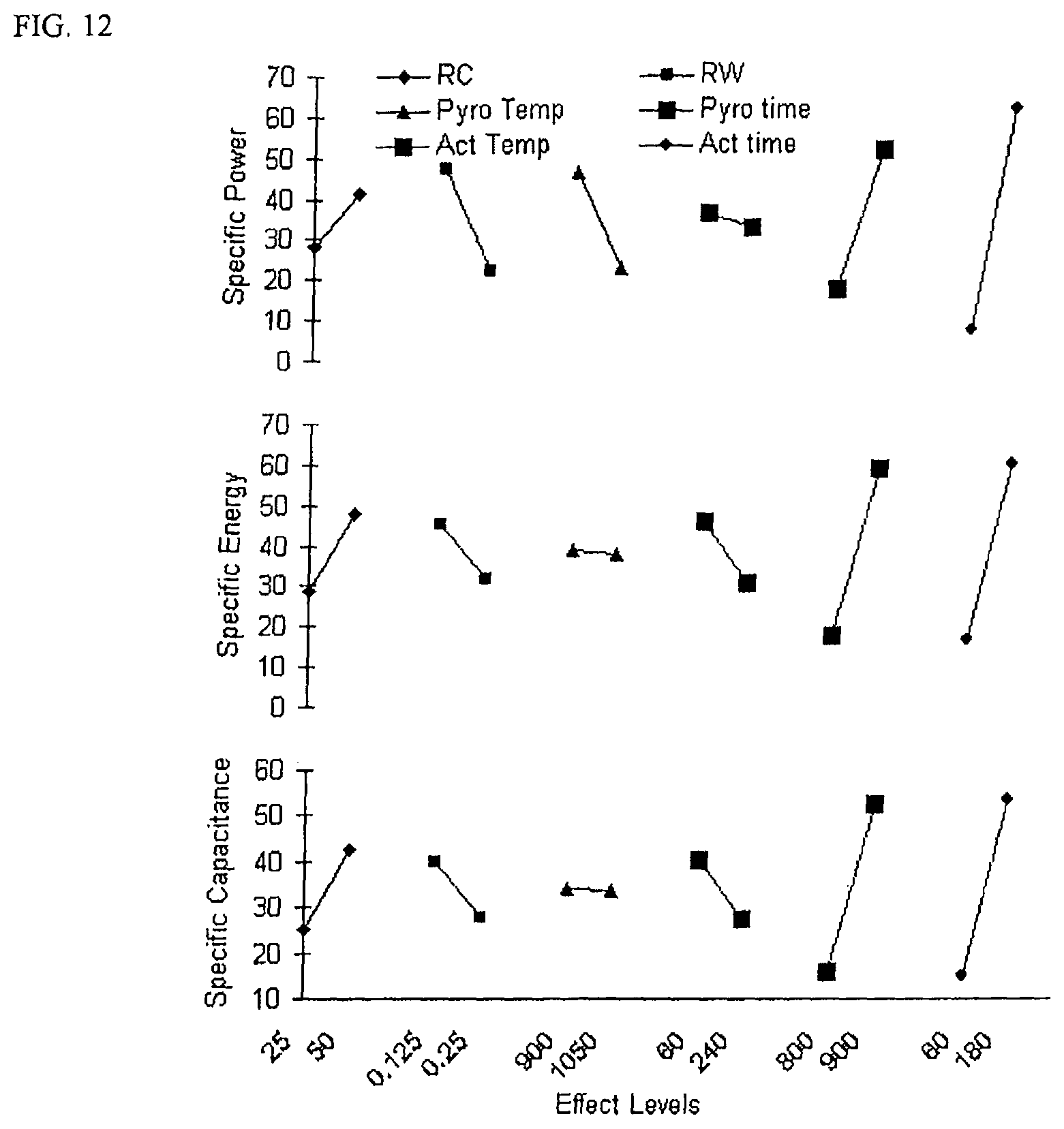
D00014
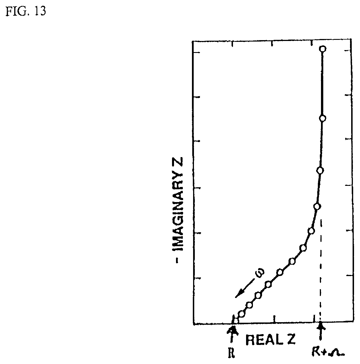
D00015
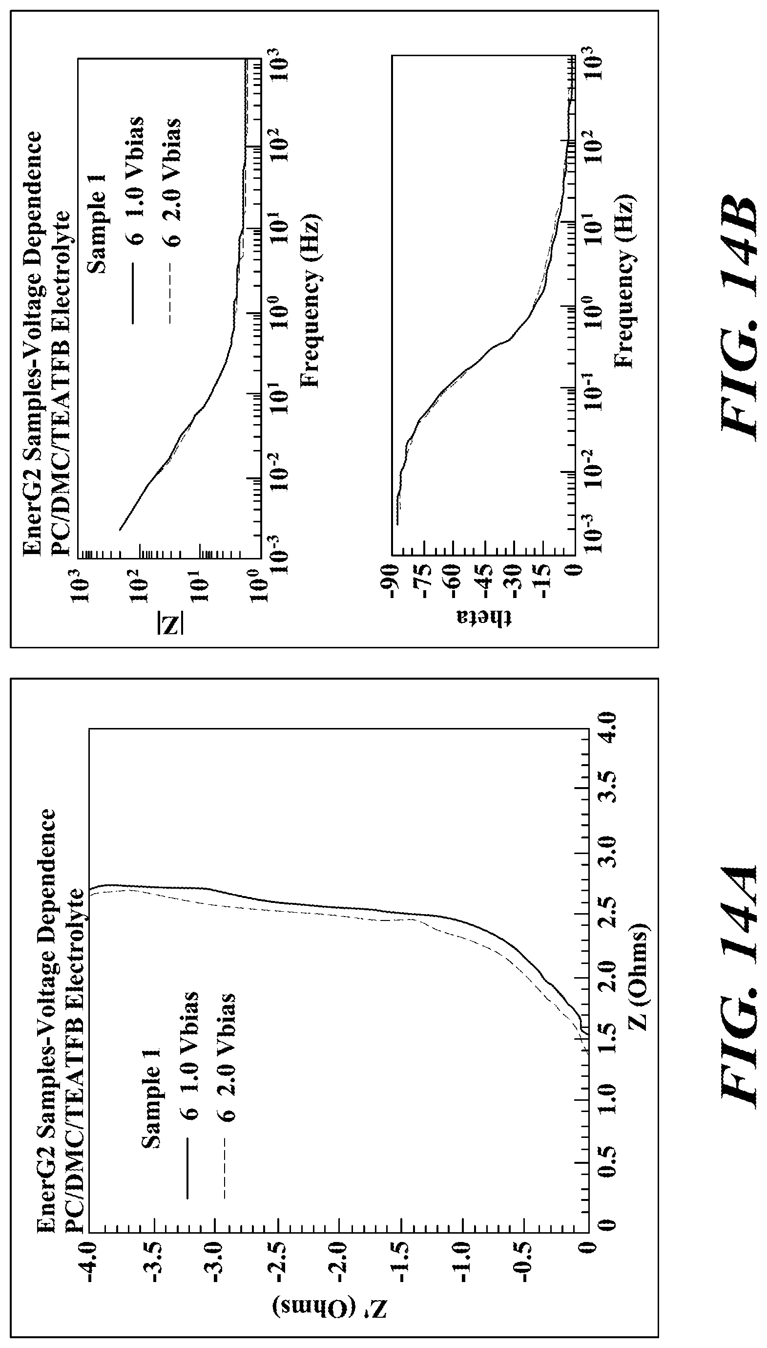
D00016

D00017
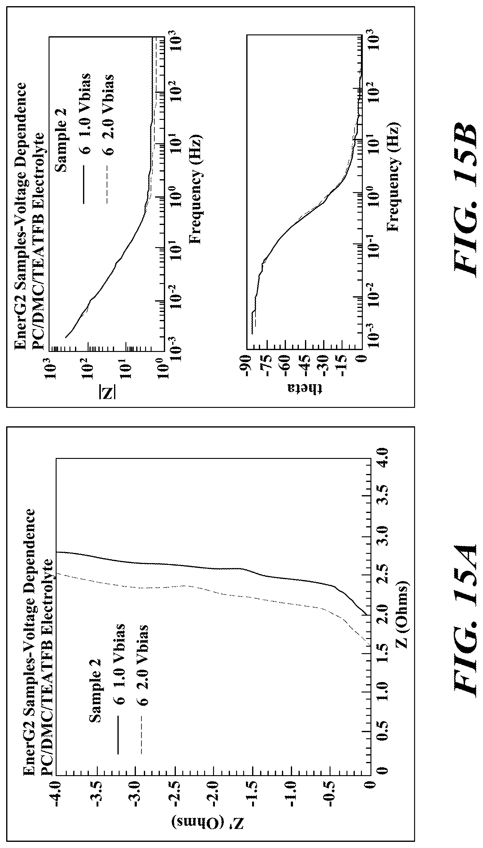
D00018

D00019
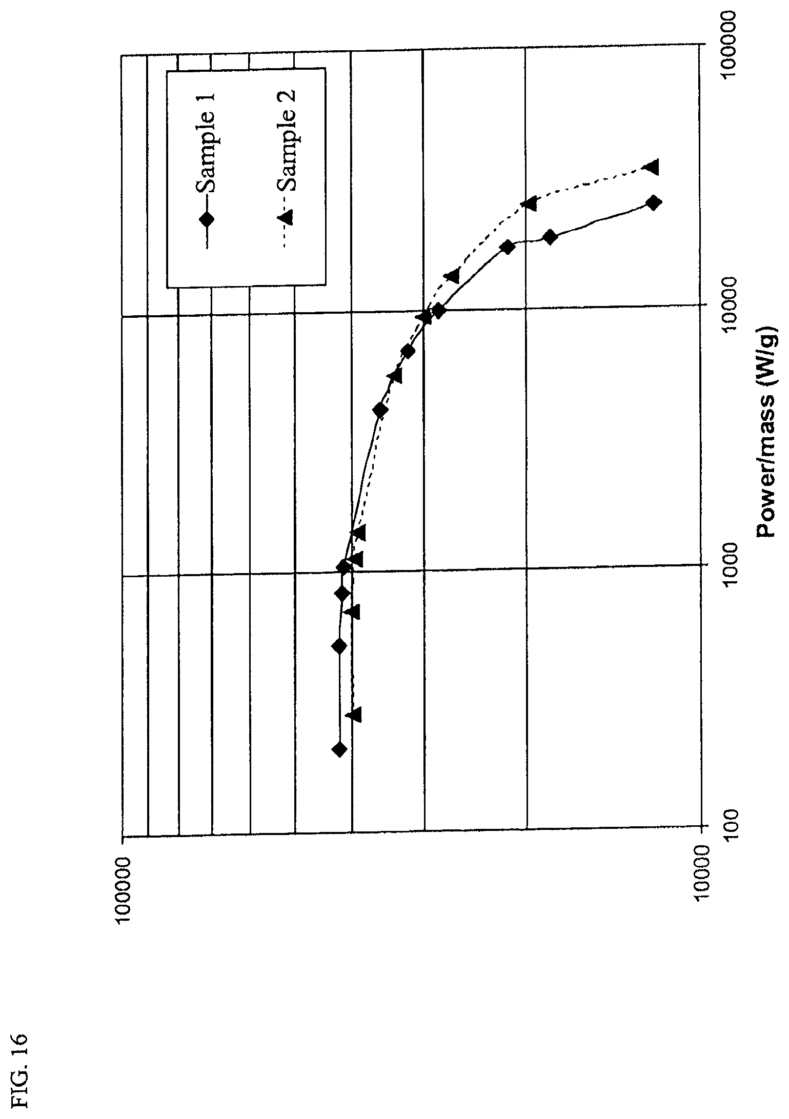
D00020
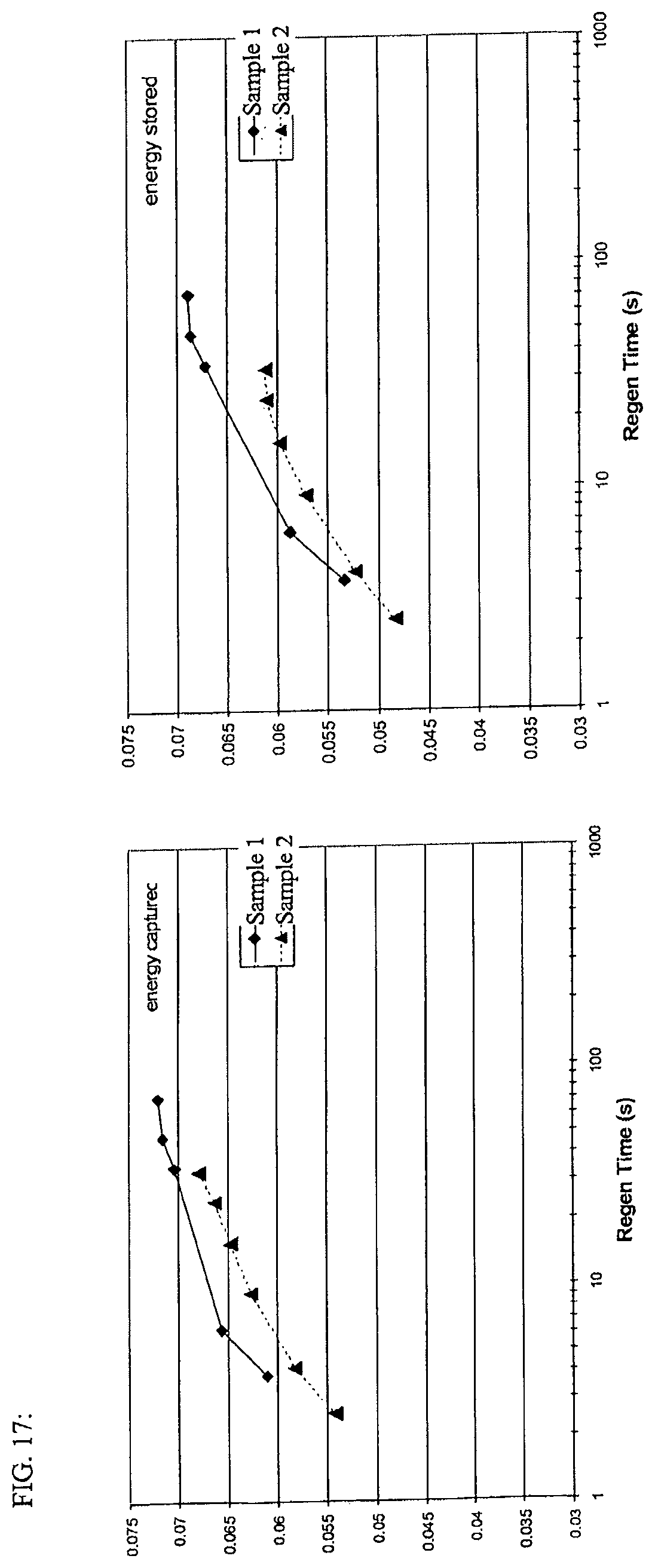
D00021
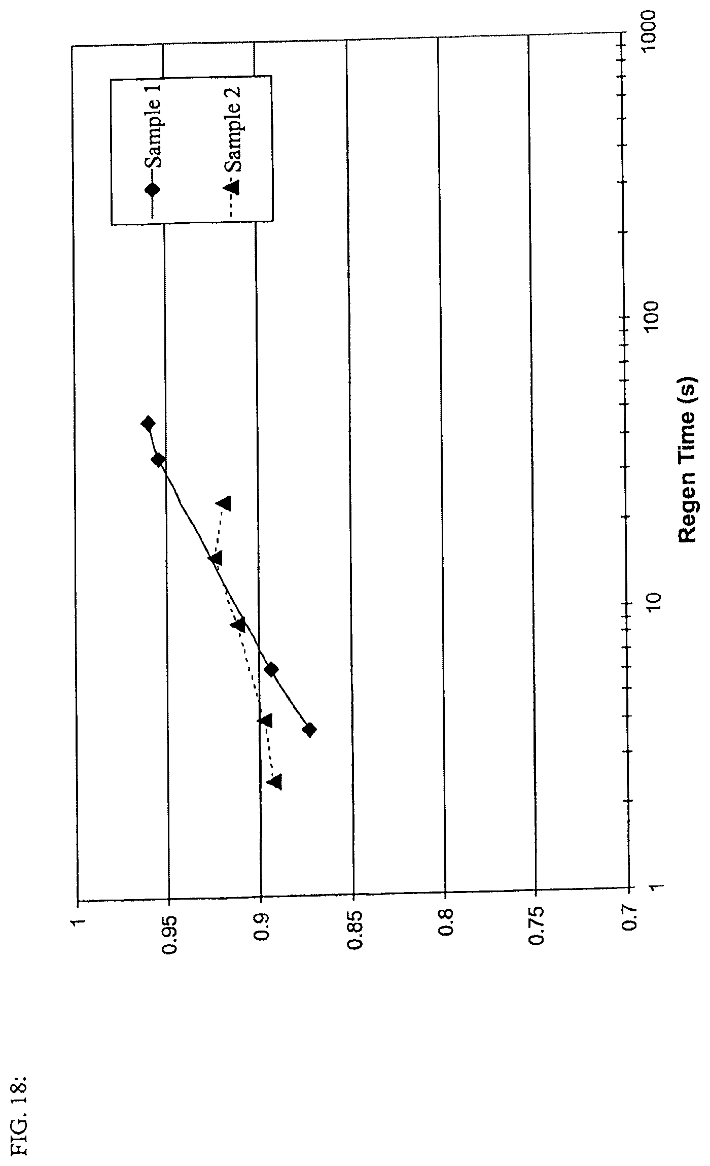
M00001
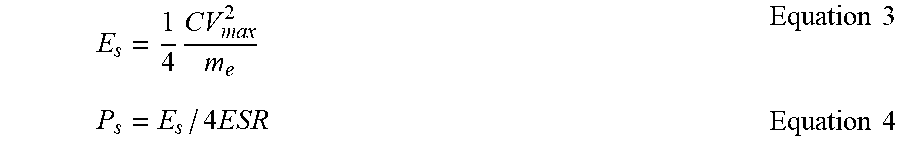
M00002

M00003

XML
uspto.report is an independent third-party trademark research tool that is not affiliated, endorsed, or sponsored by the United States Patent and Trademark Office (USPTO) or any other governmental organization. The information provided by uspto.report is based on publicly available data at the time of writing and is intended for informational purposes only.
While we strive to provide accurate and up-to-date information, we do not guarantee the accuracy, completeness, reliability, or suitability of the information displayed on this site. The use of this site is at your own risk. Any reliance you place on such information is therefore strictly at your own risk.
All official trademark data, including owner information, should be verified by visiting the official USPTO website at www.uspto.gov. This site is not intended to replace professional legal advice and should not be used as a substitute for consulting with a legal professional who is knowledgeable about trademark law.