Insertion instrument, adapter assemblies and protector assemblies for a flexible circular stapler
Racenet , et al.
U.S. patent number 10,595,871 [Application Number 15/583,594] was granted by the patent office on 2020-03-24 for insertion instrument, adapter assemblies and protector assemblies for a flexible circular stapler. This patent grant is currently assigned to Covidien LP. The grantee listed for this patent is Covidien LP. Invention is credited to Stanislaw Marczyk, Russell Pribanic, David Racenet.


View All Diagrams
| United States Patent | 10,595,871 |
| Racenet , et al. | March 24, 2020 |
Insertion instrument, adapter assemblies and protector assemblies for a flexible circular stapler
Abstract
An adapter assembly for connecting a handle assembly with a loading unit is provided. The adapter assembly includes a housing, an elongate body extending from the housing, and a trocar assembly supported within the elongate body and including a trocar member. The trocar member extends from the elongate body and is magnetized. Also provided are various assemblies for protecting the distal end of a surgical stapler during introduction of the surgical stapler within a patient.
| Inventors: | Racenet; David (Killingworth, CT), Pribanic; Russell (Roxbury, CT), Marczyk; Stanislaw (Stratford, CT) | ||||||||||
|---|---|---|---|---|---|---|---|---|---|---|---|
| Applicant: |
|
||||||||||
| Assignee: | Covidien LP (Mansfield,
MA) |
||||||||||
| Family ID: | 58692436 | ||||||||||
| Appl. No.: | 15/583,594 | ||||||||||
| Filed: | May 1, 2017 |
Prior Publication Data
| Document Identifier | Publication Date | |
|---|---|---|
| US 20170325817 A1 | Nov 16, 2017 | |
Related U.S. Patent Documents
| Application Number | Filing Date | Patent Number | Issue Date | ||
|---|---|---|---|---|---|
| 62334145 | May 10, 2016 | ||||
| Current U.S. Class: | 1/1 |
| Current CPC Class: | A61B 17/07207 (20130101); A61B 17/1155 (20130101); A61B 2017/00477 (20130101); A61B 2017/00876 (20130101); A61B 2217/007 (20130101); A61B 2017/00323 (20130101); A61B 2090/309 (20160201); A61B 34/30 (20160201); A61B 90/361 (20160201); A61B 2017/00557 (20130101); A61B 90/30 (20160201); A61B 2017/07285 (20130101); A61B 2017/00734 (20130101); A61B 2090/08021 (20160201); A61B 2017/00473 (20130101); A61B 2017/00336 (20130101); A61B 2017/0046 (20130101) |
| Current International Class: | A61B 17/115 (20060101); A61B 17/072 (20060101); A61B 90/00 (20160101); A61B 90/30 (20160101); A61B 34/30 (20160101); A61B 17/00 (20060101) |
| Field of Search: | ;227/179.1 |
References Cited [Referenced By]
U.S. Patent Documents
| 3193165 | July 1965 | Akhalaya et al. |
| 3388847 | June 1968 | Kasulin et al. |
| 3552626 | January 1971 | Astafiev et al. |
| 3638652 | February 1972 | Kelley |
| 3771526 | November 1973 | Rudie |
| 4198982 | April 1980 | Fortner et al. |
| 4207898 | June 1980 | Becht |
| 4289133 | September 1981 | Rothfuss |
| 4304236 | December 1981 | Conta et al. |
| 4319576 | March 1982 | Rothfuss |
| 4350160 | September 1982 | Kolesov et al. |
| 4351466 | September 1982 | Noiles |
| 4379457 | April 1983 | Gravener et al. |
| 4473077 | September 1984 | Noiles et al. |
| 4476863 | October 1984 | Kanshin et al. |
| 4485817 | December 1984 | Swiggett |
| 4488523 | December 1984 | Shichman |
| 4505272 | March 1985 | Utyamyshev et al. |
| 4505414 | March 1985 | Filipi |
| 4520817 | June 1985 | Green |
| 4550870 | November 1985 | Krumme et al. |
| 4573468 | March 1986 | Conta et al. |
| 4576167 | March 1986 | Noiles |
| 4592354 | June 1986 | Rothfuss |
| 4603693 | August 1986 | Conta et al. |
| 4606343 | August 1986 | Conta et al. |
| 4632290 | December 1986 | Green et al. |
| 4646745 | March 1987 | Noiles |
| 4665917 | May 1987 | Clanton et al. |
| 4667673 | May 1987 | Li |
| 4671445 | June 1987 | Barker et al. |
| 4700703 | October 1987 | Resnick et al. |
| 4703887 | November 1987 | Clanton et al. |
| 4708141 | November 1987 | Inoue et al. |
| 4717063 | January 1988 | Ebihara |
| 4752024 | June 1988 | Green et al. |
| 4754909 | July 1988 | Barker et al. |
| 4776506 | October 1988 | Green |
| 4817847 | April 1989 | Redtenbacher et al. |
| 4873977 | October 1989 | Avant et al. |
| 4893662 | January 1990 | Gervasi |
| 4903697 | February 1990 | Resnick et al. |
| 4907591 | March 1990 | Vasconcellos et al. |
| 4917114 | April 1990 | Green et al. |
| 4957499 | September 1990 | Lipatov et al. |
| 4962877 | October 1990 | Hervas |
| 5005749 | April 1991 | Aranyi |
| 5042707 | August 1991 | Taheri |
| 5047039 | September 1991 | Avant et al. |
| 5104025 | April 1992 | Main et al. |
| 5119983 | June 1992 | Green et al. |
| 5122156 | June 1992 | Granger et al. |
| 5139513 | August 1992 | Segato |
| 5158222 | October 1992 | Green et al. |
| 5188638 | February 1993 | Tzakis |
| 5193731 | March 1993 | Aranyi |
| 5197648 | March 1993 | Gingold |
| 5197649 | March 1993 | Bessler et al. |
| 5205459 | April 1993 | Brinkerhoff et al. |
| 5221036 | June 1993 | Takase |
| 5222963 | June 1993 | Brinkerhoff et al. |
| 5253793 | October 1993 | Green et al. |
| 5261920 | November 1993 | Main et al. |
| 5271543 | December 1993 | Grant et al. |
| 5271544 | December 1993 | Fox et al. |
| 5275322 | January 1994 | Brinkerhoff et al. |
| 5282810 | February 1994 | Allen et al. |
| 5285944 | February 1994 | Green et al. |
| 5285945 | February 1994 | Brinkerhoff et al. |
| 5292053 | March 1994 | Bilotti et al. |
| 5309927 | May 1994 | Welch |
| 5312024 | May 1994 | Grant et al. |
| 5314435 | May 1994 | Green et al. |
| 5314436 | May 1994 | Wilk |
| 5330486 | July 1994 | Wilk |
| 5333773 | August 1994 | Main |
| 5344059 | September 1994 | Green et al. |
| 5346115 | September 1994 | Perouse et al. |
| 5348259 | September 1994 | Blanco et al. |
| 5350104 | September 1994 | Main |
| 5355897 | October 1994 | Pietrafitta et al. |
| 5360154 | November 1994 | Green |
| 5368215 | November 1994 | Green et al. |
| 5392979 | February 1995 | Green et al. |
| 5395030 | March 1995 | Kuramoto et al. |
| 5403333 | April 1995 | Kaster et al. |
| 5404870 | April 1995 | Brinkerhoff et al. |
| 5411508 | May 1995 | Bessler et al. |
| 5425738 | June 1995 | Gustafson et al. |
| 5433721 | July 1995 | Hooven et al. |
| 5437684 | August 1995 | Calabrese et al. |
| 5439156 | August 1995 | Grant et al. |
| 5443198 | August 1995 | Viola et al. |
| 5447514 | September 1995 | Gerry et al. |
| 5454825 | October 1995 | Van Leeuwen et al. |
| 5464415 | November 1995 | Chen |
| 5470006 | November 1995 | Rodak |
| 5474223 | December 1995 | Viola et al. |
| 5497934 | March 1996 | Brady et al. |
| 5503635 | April 1996 | Sauer et al. |
| 5522534 | June 1996 | Viola et al. |
| 5533661 | July 1996 | Main et al. |
| 5588579 | December 1996 | Schnut et al. |
| 5609285 | March 1997 | Grant et al. |
| 5626591 | May 1997 | Kockerling et al. |
| 5632433 | May 1997 | Grant et al. |
| 5639008 | June 1997 | Gallagher et al. |
| 5641111 | June 1997 | Ahrens et al. |
| 5658300 | August 1997 | Bito et al. |
| 5669918 | September 1997 | Balazs et al. |
| 5685474 | November 1997 | Seeber |
| 5709335 | January 1998 | Heck |
| 5715987 | February 1998 | Kelley et al. |
| 5718360 | February 1998 | Green et al. |
| 5720755 | February 1998 | Dakov |
| 5732872 | March 1998 | Bolduc et al. |
| 5749896 | May 1998 | Cook |
| 5758814 | June 1998 | Gallagher et al. |
| 5799857 | September 1998 | Robertson et al. |
| 5814055 | September 1998 | Knodel et al. |
| 5833698 | November 1998 | Hinchliffe et al. |
| 5836503 | November 1998 | Ehrenfels et al. |
| 5839639 | November 1998 | Sauer et al. |
| 5855312 | January 1999 | Toledano |
| 5860581 | January 1999 | Robertson et al. |
| 5868760 | February 1999 | McGuckin, Jr. |
| 5881943 | March 1999 | Heck |
| 5915616 | June 1999 | Viola et al. |
| 5947363 | September 1999 | Bolduc et al. |
| 5951576 | September 1999 | Wakabayashi |
| 5957363 | September 1999 | Heck |
| 5993468 | November 1999 | Rygaard |
| 6024748 | February 2000 | Manzo et al. |
| 6050472 | April 2000 | Shibata |
| 6053390 | April 2000 | Green et al. |
| 6068636 | May 2000 | Chen |
| 6083241 | July 2000 | Longo et al. |
| 6102271 | August 2000 | Longo et al. |
| 6117148 | September 2000 | Ravo et al. |
| 6119913 | September 2000 | Adams et al. |
| 6126058 | October 2000 | Adams et al. |
| 6142933 | November 2000 | Longo et al. |
| 6149667 | November 2000 | Hovland et al. |
| 6176413 | January 2001 | Heck et al. |
| 6179195 | January 2001 | Adams et al. |
| 6193129 | February 2001 | Bittner et al. |
| 6203553 | March 2001 | Robertson et al. |
| 6209773 | April 2001 | Bolduc et al. |
| 6241140 | June 2001 | Adams et al. |
| 6253984 | July 2001 | Heck et al. |
| 6258107 | July 2001 | Balazs et al. |
| 6264086 | July 2001 | McGuckin, Jr. |
| 6269997 | August 2001 | Balazs et al. |
| 6273897 | August 2001 | Dalessandro et al. |
| 6279809 | August 2001 | Nicolo |
| 6302311 | October 2001 | Adams et al. |
| 6338737 | January 2002 | Toledano |
| 6343731 | February 2002 | Adams et al. |
| 6387105 | May 2002 | Gifford, III et al. |
| 6398795 | June 2002 | McAlister et al. |
| 6402008 | June 2002 | Lucas |
| 6439446 | August 2002 | Perry et al. |
| 6443973 | September 2002 | Whitman |
| 6450390 | September 2002 | Heck et al. |
| 6478210 | November 2002 | Adams et al. |
| 6488197 | December 2002 | Whitman |
| 6491201 | December 2002 | Whitman |
| 6494877 | December 2002 | Odell et al. |
| 6503259 | January 2003 | Huxel et al. |
| 6517566 | February 2003 | Hovland et al. |
| 6520398 | February 2003 | Nicolo |
| 6533157 | March 2003 | Whitman |
| 6551334 | April 2003 | Blatter et al. |
| 6578751 | June 2003 | Hartwick |
| 6585144 | July 2003 | Adams et al. |
| 6588643 | July 2003 | Bolduc et al. |
| 6592596 | July 2003 | Geitz |
| 6601749 | August 2003 | Sullivan et al. |
| 6605078 | August 2003 | Adams |
| 6605098 | August 2003 | Nobis et al. |
| 6626921 | September 2003 | Blatter et al. |
| 6629630 | October 2003 | Adams |
| 6631837 | October 2003 | Heck |
| 6632227 | October 2003 | Adams |
| 6632237 | October 2003 | Ben-David et al. |
| 6652542 | November 2003 | Blatter et al. |
| 6659327 | December 2003 | Heck et al. |
| 6676671 | January 2004 | Robertson et al. |
| 6681979 | January 2004 | Whitman |
| 6685079 | February 2004 | Sharma et al. |
| 6695198 | February 2004 | Adams et al. |
| 6695199 | February 2004 | Whitman |
| 6698643 | March 2004 | Whitman |
| 6716222 | April 2004 | McAlister et al. |
| 6716233 | April 2004 | Whitman |
| 6726697 | April 2004 | Nicholas et al. |
| 6742692 | June 2004 | Hartwick |
| 6743244 | June 2004 | Blatter et al. |
| 6763993 | July 2004 | Bolduc et al. |
| 6769590 | August 2004 | Vresh et al. |
| 6769594 | August 2004 | Orban, III |
| 6820791 | November 2004 | Adams |
| 6821282 | November 2004 | Perry et al. |
| 6827246 | December 2004 | Sullivan et al. |
| 6840423 | January 2005 | Adams et al. |
| 6843403 | January 2005 | Whitman |
| 6846308 | January 2005 | Whitman et al. |
| 6852122 | February 2005 | Rush |
| 6866178 | March 2005 | Adams et al. |
| 6872214 | March 2005 | Sonnenschein et al. |
| 6874669 | April 2005 | Adams et al. |
| 6884250 | April 2005 | Monassevitch et al. |
| 6905504 | June 2005 | Vargas |
| 6938814 | September 2005 | Sharma |
| 6942675 | September 2005 | Vargas |
| 6945444 | September 2005 | Gresham et al. |
| 6953138 | October 2005 | Dworak et al. |
| 6957758 | October 2005 | Aranyi |
| 6959851 | November 2005 | Heinrich |
| 6978922 | December 2005 | Bilotti et al. |
| 6981941 | January 2006 | Whitman et al. |
| 6981979 | January 2006 | Nicolo |
| 7032798 | April 2006 | Whitman et al. |
| 7059331 | June 2006 | Adams et al. |
| 7059510 | June 2006 | Orban, III |
| 7077856 | July 2006 | Whitman |
| 7080769 | July 2006 | Vresh et al. |
| 7086267 | August 2006 | Dworak et al. |
| 7114642 | October 2006 | Whitman |
| 7118528 | October 2006 | Piskun |
| 7122044 | October 2006 | Bolduc et al. |
| 7128748 | October 2006 | Mooradian et al. |
| 7141055 | November 2006 | Abrams et al. |
| 7168604 | January 2007 | Milliman et al. |
| 7179267 | February 2007 | Nolan et al. |
| 7182239 | February 2007 | Myers |
| 7195142 | March 2007 | Orban, III |
| 7207168 | April 2007 | Doepker et al. |
| 7220237 | May 2007 | Gannoe et al. |
| 7234624 | June 2007 | Gresham et al. |
| 7235089 | June 2007 | McGuckin, Jr. |
| RE39841 | September 2007 | Bilotti et al. |
| 7285125 | October 2007 | Viola |
| 7303106 | December 2007 | Milliman et al. |
| 7303107 | December 2007 | Milliman et al. |
| 7309341 | December 2007 | Ortiz et al. |
| 7322994 | January 2008 | Nicholas et al. |
| 7325713 | February 2008 | Aranyi |
| 7334718 | February 2008 | McAlister et al. |
| 7335212 | February 2008 | Edoga et al. |
| 7364060 | April 2008 | Milliman |
| 7398908 | July 2008 | Holsten et al. |
| 7399305 | July 2008 | Csiky et al. |
| 7401721 | July 2008 | Holsten et al. |
| 7401722 | July 2008 | Hur |
| 7407075 | August 2008 | Holsten et al. |
| 7410086 | August 2008 | Ortiz et al. |
| 7422137 | September 2008 | Manzo |
| 7422138 | September 2008 | Bilotti et al. |
| 7431191 | October 2008 | Milliman |
| 7438718 | October 2008 | Milliman et al. |
| 7455676 | November 2008 | Holsten et al. |
| 7455682 | November 2008 | Viola |
| 7481347 | January 2009 | Roy |
| 7494038 | February 2009 | Milliman |
| 7506791 | March 2009 | Omaits et al. |
| 7516877 | April 2009 | Aranyi |
| 7527185 | May 2009 | Harari et al. |
| 7537602 | May 2009 | Whitman |
| 7540839 | June 2009 | Butler et al. |
| 7546939 | June 2009 | Adams et al. |
| 7546940 | June 2009 | Milliman et al. |
| 7547312 | June 2009 | Bauman et al. |
| 7556186 | July 2009 | Milliman |
| 7559451 | July 2009 | Sharma et al. |
| 7585306 | September 2009 | Abbott et al. |
| 7588174 | September 2009 | Holsten et al. |
| 7600663 | October 2009 | Green |
| 7611038 | November 2009 | Racenet et al. |
| 7635385 | December 2009 | Milliman et al. |
| 7669747 | March 2010 | Weisenburgh, II et al. |
| 7686201 | March 2010 | Csiky |
| 7694864 | April 2010 | Okada et al. |
| 7699204 | April 2010 | Viola |
| 7708181 | May 2010 | Cole et al. |
| 7717313 | May 2010 | Criscuolo et al. |
| 7721932 | May 2010 | Cole et al. |
| 7726539 | June 2010 | Holsten et al. |
| 7743958 | June 2010 | Orban, III |
| 7744627 | June 2010 | Orban, III et al. |
| 7770776 | August 2010 | Chen et al. |
| 7771440 | August 2010 | Ortiz et al. |
| 7776060 | August 2010 | Mooradian et al. |
| 7793813 | September 2010 | Bettuchi |
| 7802712 | September 2010 | Milliman et al. |
| 7823592 | November 2010 | Bettuchi et al. |
| 7837079 | November 2010 | Holsten et al. |
| 7837080 | November 2010 | Schwemberger |
| 7837081 | November 2010 | Holsten et al. |
| 7845536 | December 2010 | Viola et al. |
| 7845538 | December 2010 | Whitman |
| 7857187 | December 2010 | Milliman |
| 7886951 | February 2011 | Hessler |
| 7896215 | March 2011 | Adams et al. |
| 7900806 | March 2011 | Chen et al. |
| 7909039 | March 2011 | Hur |
| 7909219 | March 2011 | Cole et al. |
| 7909222 | March 2011 | Cole et al. |
| 7909223 | March 2011 | Cole et al. |
| 7913892 | March 2011 | Cole et al. |
| 7918377 | April 2011 | Measamer et al. |
| 7922062 | April 2011 | Cole et al. |
| 7922743 | April 2011 | Heinrich et al. |
| 7931183 | April 2011 | Orban, III |
| 7938307 | May 2011 | Bettuchi |
| 7942302 | May 2011 | Roby et al. |
| 7951166 | May 2011 | Orban, III et al. |
| 7959050 | June 2011 | Smith et al. |
| 7967181 | June 2011 | Viola et al. |
| 7975895 | July 2011 | Milliman |
| 8002795 | August 2011 | Beetel |
| 8006701 | August 2011 | Bilotti et al. |
| 8006889 | August 2011 | Adams et al. |
| 8011551 | September 2011 | Marczyk et al. |
| 8011554 | September 2011 | Milliman |
| 8016177 | September 2011 | Bettuchi et al. |
| 8016858 | September 2011 | Whitman |
| 8020741 | September 2011 | Cole et al. |
| 8025199 | September 2011 | Whitman et al. |
| 8028885 | October 2011 | Smith et al. |
| 8038046 | October 2011 | Smith et al. |
| 8043207 | October 2011 | Adams |
| 8066167 | November 2011 | Measamer et al. |
| 8066169 | November 2011 | Viola |
| 8070035 | December 2011 | Holsten et al. |
| 8070037 | December 2011 | Csiky |
| 8096458 | January 2012 | Hessler |
| 8109426 | February 2012 | Milliman et al. |
| 8109427 | February 2012 | Orban, III |
| 8113406 | February 2012 | Holsten et al. |
| 8113407 | February 2012 | Holsten et al. |
| 8123103 | February 2012 | Milliman |
| 8128645 | March 2012 | Sonnenschein et al. |
| 8132703 | March 2012 | Milliman et al. |
| 8136712 | March 2012 | Zingman |
| 8146790 | April 2012 | Milliman |
| 8146791 | April 2012 | Bettuchi et al. |
| 8181838 | May 2012 | Milliman et al. |
| 8192460 | June 2012 | Orban, III et al. |
| 8201720 | June 2012 | Hessler |
| 8203782 | June 2012 | Brueck et al. |
| 8211130 | July 2012 | Viola |
| 8225799 | July 2012 | Bettuchi |
| 8225981 | July 2012 | Criscuolo et al. |
| 8231041 | July 2012 | Marczyk et al. |
| 8231042 | July 2012 | Hessler et al. |
| 8257391 | September 2012 | Orban, III et al. |
| 8267301 | September 2012 | Milliman et al. |
| 8272552 | September 2012 | Holsten et al. |
| 8276802 | October 2012 | Kostrzewski |
| 8281975 | October 2012 | Criscuolo et al. |
| 8286845 | October 2012 | Perry et al. |
| 8308045 | November 2012 | Bettuchi et al. |
| 8312885 | November 2012 | Bettuchi et al. |
| 8313014 | November 2012 | Bettuchi |
| 8317073 | November 2012 | Milliman et al. |
| 8317074 | November 2012 | Ortiz et al. |
| 8322590 | December 2012 | Patel et al. |
| 8328060 | December 2012 | Jankowski et al. |
| 8328062 | December 2012 | Viola |
| 8328063 | December 2012 | Milliman et al. |
| 8343185 | January 2013 | Milliman et al. |
| 8353438 | January 2013 | Baxter, III et al. |
| 8353439 | January 2013 | Baxter, III et al. |
| 8353930 | January 2013 | Heinrich et al. |
| 8360295 | January 2013 | Milliman et al. |
| 8365974 | February 2013 | Milliman |
| 8403942 | March 2013 | Milliman et al. |
| 8408441 | April 2013 | Wenchell et al. |
| 8413870 | April 2013 | Pastorelli et al. |
| 8413872 | April 2013 | Patel |
| 8418905 | April 2013 | Milliman |
| 8418909 | April 2013 | Kostrzewski |
| 8424535 | April 2013 | Hessler et al. |
| 8424741 | April 2013 | McGuckin, Jr. et al. |
| 8430291 | April 2013 | Heinrich et al. |
| 8430292 | April 2013 | Patel et al. |
| 8453910 | June 2013 | Bettuchi et al. |
| 8453911 | June 2013 | Milliman et al. |
| 8485414 | July 2013 | Criscuolo et al. |
| 8490853 | July 2013 | Criscuolo et al. |
| 8511533 | August 2013 | Viola et al. |
| 8551138 | October 2013 | Orban, III et al. |
| 8567655 | October 2013 | Nalagatla et al. |
| 8579178 | November 2013 | Holsten et al. |
| 8590763 | November 2013 | Milliman |
| 8590764 | November 2013 | Hartwick et al. |
| 8608047 | December 2013 | Holsten et al. |
| 8616428 | December 2013 | Milliman et al. |
| 8616429 | December 2013 | Viola |
| 8622275 | January 2014 | Baxter, III et al. |
| 8631993 | January 2014 | Kostrzewski |
| 8636187 | January 2014 | Hueil et al. |
| 8640940 | February 2014 | Ohdaira |
| 8662370 | March 2014 | Takei |
| 8663258 | March 2014 | Bettuchi et al. |
| 8672931 | March 2014 | Goldboss et al. |
| 8678264 | March 2014 | Racenet et al. |
| 8684248 | April 2014 | Milliman |
| 8684250 | April 2014 | Bettuchi et al. |
| 8684251 | April 2014 | Rebuffat et al. |
| 8684252 | April 2014 | Patel et al. |
| 8695864 | April 2014 | Hausen |
| 8733611 | May 2014 | Milliman |
| 2003/0111507 | June 2003 | Nunez |
| 2004/0073090 | April 2004 | Butler et al. |
| 2005/0051597 | March 2005 | Toledano |
| 2005/0107813 | May 2005 | Gilete Garcia |
| 2006/0000869 | January 2006 | Fontayne |
| 2006/0011698 | January 2006 | Okada et al. |
| 2006/0201989 | September 2006 | Ojeda |
| 2007/0027473 | February 2007 | Vresh et al. |
| 2007/0029363 | February 2007 | Popov |
| 2007/0060952 | March 2007 | Roby et al. |
| 2007/0075117 | April 2007 | Milliman |
| 2008/0300609 | December 2008 | Tabet |
| 2009/0236392 | September 2009 | Cole et al. |
| 2009/0236398 | September 2009 | Cole et al. |
| 2009/0236401 | September 2009 | Cole et al. |
| 2010/0019016 | January 2010 | Edoga et al. |
| 2010/0051668 | March 2010 | Milliman et al. |
| 2010/0084453 | April 2010 | Hu |
| 2010/0147923 | June 2010 | D'Agostino et al. |
| 2010/0163598 | July 2010 | Belzer |
| 2010/0224668 | September 2010 | Fontayne et al. |
| 2010/0230465 | September 2010 | Smith et al. |
| 2010/0258611 | October 2010 | Smith et al. |
| 2010/0264195 | October 2010 | Bettuchi |
| 2010/0327041 | December 2010 | Milliman et al. |
| 2011/0011916 | January 2011 | Levine |
| 2011/0114697 | May 2011 | Baxter, III et al. |
| 2011/0114700 | May 2011 | Baxter, III et al. |
| 2011/0144640 | June 2011 | Heinrich et al. |
| 2011/0147432 | June 2011 | Heinrich et al. |
| 2011/0170281 | July 2011 | Shih |
| 2011/0192882 | August 2011 | Hess et al. |
| 2012/0145755 | June 2012 | Kahn |
| 2012/0193395 | August 2012 | Pastorelli et al. |
| 2012/0193398 | August 2012 | Williams et al. |
| 2012/0232339 | September 2012 | Csiky |
| 2012/0273548 | November 2012 | Ma et al. |
| 2012/0325888 | December 2012 | Qiao et al. |
| 2013/0015232 | January 2013 | Smith et al. |
| 2013/0020372 | January 2013 | Jankowski et al. |
| 2013/0020373 | January 2013 | Smith et al. |
| 2013/0032628 | February 2013 | Li et al. |
| 2013/0056516 | March 2013 | Viola |
| 2013/0060258 | March 2013 | Giacomantonio |
| 2013/0105544 | May 2013 | Mozdzierz et al. |
| 2013/0105546 | May 2013 | Milliman et al. |
| 2013/0105551 | May 2013 | Zingman |
| 2013/0126580 | May 2013 | Smith et al. |
| 2013/0153630 | June 2013 | Miller et al. |
| 2013/0153631 | June 2013 | Vasudevan et al. |
| 2013/0153633 | June 2013 | Casasanta, Jr. et al. |
| 2013/0153634 | June 2013 | Carter et al. |
| 2013/0153638 | June 2013 | Carter et al. |
| 2013/0153639 | June 2013 | Hodgkinson et al. |
| 2013/0175315 | July 2013 | Milliman |
| 2013/0175318 | July 2013 | Felder |
| 2013/0175319 | July 2013 | Felder et al. |
| 2013/0175320 | July 2013 | Mandakolathur Vasudevan |
| 2013/0181035 | July 2013 | Milliman |
| 2013/0181036 | July 2013 | Olson et al. |
| 2013/0186930 | July 2013 | Wenchell et al. |
| 2013/0193185 | August 2013 | Patel |
| 2013/0193187 | August 2013 | Milliman |
| 2013/0193190 | August 2013 | Carter et al. |
| 2013/0193191 | August 2013 | Stevenson et al. |
| 2013/0193192 | August 2013 | Casasanta, Jr. et al. |
| 2013/0200131 | August 2013 | Racenet et al. |
| 2013/0206816 | August 2013 | Penna |
| 2013/0214027 | August 2013 | Hessler et al. |
| 2013/0214028 | August 2013 | Patel et al. |
| 2013/0228609 | September 2013 | Kostrzewski |
| 2013/0240597 | September 2013 | Milliman et al. |
| 2013/0240600 | September 2013 | Bettuchi |
| 2013/0248581 | September 2013 | Smith et al. |
| 2013/0277411 | October 2013 | Hodgkinson et al. |
| 2013/0277412 | October 2013 | Gresham et al. |
| 2013/0284792 | October 2013 | Ma |
| 2013/0292449 | November 2013 | Bettuchi et al. |
| 2013/0299553 | November 2013 | Mozdzierz |
| 2013/0299554 | November 2013 | Mozdzierz |
| 2013/0306701 | November 2013 | Olson |
| 2013/0306707 | November 2013 | Viola et al. |
| 2014/0008413 | January 2014 | Williams |
| 2014/0012317 | January 2014 | Orban et al. |
| 2015/0141976 | May 2015 | Stulen |
| 908529 | Aug 1972 | CA | |||
| 2805365 | Aug 2013 | CA | |||
| 1057729 | May 1959 | DE | |||
| 3301713 | Jul 1984 | DE | |||
| 0152382 | Aug 1985 | EP | |||
| 0173451 | Mar 1986 | EP | |||
| 0190022 | Aug 1986 | EP | |||
| 0282157 | Sep 1988 | EP | |||
| 0503689 | Sep 1992 | EP | |||
| 1354560 | Oct 2003 | EP | |||
| 2138118 | Dec 2009 | EP | |||
| 2168510 | Mar 2010 | EP | |||
| 2238926 | Oct 2010 | EP | |||
| 2524656 | Nov 2012 | EP | |||
| 2799026 | Nov 2014 | EP | |||
| 2954857 | Dec 2015 | EP | |||
| 2992841 | Mar 2016 | EP | |||
| 1136020 | May 1957 | FR | |||
| 1461464 | Feb 1966 | FR | |||
| 1588250 | Apr 1970 | FR | |||
| 2443239 | Jul 1980 | FR | |||
| 1185292 | Mar 1970 | GB | |||
| 2016991 | Sep 1979 | GB | |||
| 2070499 | Sep 1981 | GB | |||
| 2004147969 | May 2004 | JP | |||
| 2013-138860 | Jul 2013 | JP | |||
| 7711347 | Apr 1979 | NL | |||
| 1509052 | Sep 1989 | SU | |||
| 8706448 | Nov 1987 | WO | |||
| 8900406 | Jan 1989 | WO | |||
| 9006085 | Jun 1990 | WO | |||
| 98/35614 | Aug 1998 | WO | |||
| 2001/054594 | Aug 2001 | WO | |||
| 2006014881 | Feb 2006 | WO | |||
| 2008/107918 | Sep 2008 | WO | |||
| 2011149876 | Dec 2011 | WO | |||
| 2015073425 | May 2015 | WO | |||
Other References
|
European Search Report dated Dec. 11, 2017, issued in EP Application No. 17170075. cited by applicant . European Search Report dated Sep. 6, 2017, issued in EP Application No. 17170075. cited by applicant. |
Primary Examiner: Chukwurah; Nathaniel C
Attorney, Agent or Firm: Carter, DeLuca & Farrell LLP
Parent Case Text
CROSS-REFERENCE TO RELATED APPLICATIONS
This application claims the benefit of and priority to U.S. Provisional Patent Application Ser. No. 62/334,145, filed May 10, 2016, the entire disclosure of which is incorporated by reference herein.
Claims
What is claimed is:
1. An adapter assembly for connecting a handle assembly with a loading unit, the adapter assembly comprising: a housing; an elongate body extending from the housing; a trocar assembly supported within the elongate body and including a trocar member, wherein the trocar member extends from the elongate body, wherein the trocar member includes a distal portion having a first polarity and a proximal portion having a second polarity; and an anvil assembly including a center rod releasably securable to the trocar assembly, the center rod including a proximal portion having the second polarity and a distal portion having a first polarity.
2. The adapter assembly of claim 1, wherein the anvil assembly includes a removable tip, the removable tip being magnetized to compliment the trocar member such that the removable tip is magnetically attracted to the trocar member.
3. The adapter assembly of claim 1, wherein the trocar assembly includes an electromagnet received about the trocar member for selectively magnetizing the trocar member.
4. The adapter assembly of claim 1, further including a light source.
5. The adapter assembly of claim 1, further including an electromagnet assembly, wherein the electromagnet assembly provides the trocar member with the first and second polarities.
6. The adapter assembly of claim 5, further including a power source for selectively providing power to the electromagnet assembly.
7. The adapter assembly of claim 6, further including a switch operably disposed between the power source and the electromagnet assembly for selectively providing power to the electromagnet assembly.
8. The adapter assembly of claim 5, wherein the electromagnet assembly includes a wire coil.
9. The adapter assembly of claim 5, wherein the electromagnet assembly includes a solenoid.
10. An adapter assembly for connecting a handle assembly with a loading unit, the adapter assembly comprising: an elongate body; a loading unit disposed on a distal end of the elongate body, the loading unit including a selectively activated electromagnet assembly; and a trocar assembly selectively extendable relative to the loading unit and including a trocar member, wherein the trocar member is operably coupled with the electromagnet assembly such that activation of the electromagnet assembly magnetizes the trocar member.
11. The adapter assembly of claim 10, further including an anvil assembly, wherein the anvil assembly includes a center rod configured to be attracted to the trocar member when the electromagnet assembly is activated.
12. The adapter assembly of claim 10, further including a power source for selectively providing power to the electromagnet assembly.
13. The adapter assembly of claim 12, further including a switch operably disposed between the power source and the electromagnet assembly for selectively providing power to the electromagnet assembly.
14. The adapter assembly of claim 10, wherein the electromagnet assembly includes a wire coil.
15. The adapter assembly of claim 10, wherein the electromagnet assembly includes a solenoid.
Description
BACKGROUND
Technical Field
The present disclosure relates to surgical stapling devices. More particularly, the present disclosure relates to insertion instruments, adapter assemblies, and protector assemblies for powered flexible circular staplers.
Background of Related Art
Circular staplers are used to perform end to end anastomosis. During a typical surgical procedure, an anvil of the circular stapler is delivered to the surgical site while a staple cartridge of the circular stapler supported on an elongate shaft is inserted through an incision in, for example, the abdominal wall. Alternatively, the circular stapler may include a flexible shaft that permits introduction of the staple cartridge to the surgical site through a natural body orifice, e.g., mouth or anus. The circular staplers may be manual or powered, and may be modified for use with robotic surgical systems.
In order to better facilitate introduction and positioning of a flexible shaft of the circular staplers, it would be beneficial to have a circular stapler that includes an efficient mechanism for connecting the anvil assembly of the circular stapler to the elongate body of the circular stapler during a surgical procedure. It would also be beneficial to have an introducer that minimizes risk of damage to the patient and/or to the circular stapler during, for example, introduction of the circular stapler into a patient. It would further be beneficial to have a circular stapler that increases visualization of the surgical procedure. It would also be beneficial to have a circular stapler with an elongated body capable of accommodate a guide wire and/or that allows for injecting saline to an anastomosis site to, for example, test a seal and ease manipulation.
SUMMARY
An adapter assembly for connecting a handle assembly with a loading unit is provided. The adapter assembly includes a housing, an elongate body extending from the housing, and a trocar assembly supported within the elongate body and including a trocar member. The trocar member extends from the elongate body. wherein the trocar member is magnetized.
In embodiments, the adapter assembly includes an anvil assembly. The anvil assembly may include a center rod magnetized to compliment the trocar member such that the center rod is magnetically attracted to the trocar member. The anvil assembly may include a removable tip. The removable tip may be magnetized to compliment the trocar member such that the removable tip is magnetically attracted to the trocar member. The trocar assembly may include an electromagnet received about the trocar member for selectively magnetizing the trocar member. The adapter assembly may further include a light source.
Also provided is an insertion instrument for facilitating placement of an anvil assembly within a patient. The insertion instrument includes a handle assembly, an elongate body extending from the handle assembly, an electromagnet including a coil of wire received around a ferromagnetic member, the electromagnet being disposed on a distal end of the elongate body, and a light source disposed on a distal end of the elongate body. In embodiments, the insertion instrument includes a first switch assembly for selectively activating the electromagnet. The insertion instrument may include a second switch assembly for selectively activating the light source.
Another assembly for protecting the functional end of a surgical stapler during introduction of the surgical stapler within a patient is provided. The assembly includes a sleeve having proximal and distal ends and being receivable about an elongate body. The sleeve defines an inflatable cavity on the distal end configured to be disposed adjacent a distal end of the elongate body. The assembly also includes an insufflation port in fluid communication with the inflatable cavity for selectively inflating the inflatable cavity.
In embodiments, the sleeve further defines a weakened portion extending along the length of the sleeve. The sleeve may include a handle portion on the proximal end. The assembly may include a source of insufflation fluid. The source of insufflation fluid may include a syringe.
An assembly for protecting the functional end of a surgical stapler is also provided. The assembly includes a sleeve having proximal and distal ends, and a cap member secured to the distal end of the sleeve. The cap member may include a plurality of leaves connected to each other by a frangible connection. The frangible connection may include a weakened bridge.
In embodiments, the sleeve includes a handle portion on the proximal end. The sleeve may further define a weakened portion extending along the length of the sleeve. The assembly may also include a camera disposed on a distal end of the cap member. The assembly may include a steering assembly having a steering ring and a plurality of steering cables secured to the steering ring. The plurality of steering cables may extend the length of the sleeve.
Also provided is an assembly for protecting a distal end of circular stapling apparatus. The assembly includes an inflatable member having a first portion and a second portion, wherein the first portion is smaller than the second portion and is configured to be received within the distal end of a loading unit. The assembly also includes an insufflation port operably connected to the inflatable member for selectively inflating and deflating the inflatable member.
In embodiments, the inflatable member includes a snowman shape. Each of the first and second portions may be substantially spherical.
BRIEF DESCRIPTION OF THE DRAWINGS
The accompanying drawings, which are incorporated in and constitute a part of this specification, illustrate embodiments of the disclosure and, together with a general description of the disclosure given above, and the detailed description of the embodiment(s) given below, serve to explain the principles of the disclosure, wherein:
FIG. 1 is a side view of an exemplary handle assembly and an adapter assembly according to an embodiment of the present disclosure;
FIG. 2 is a side view of an anvil assembly according to an embodiment of the present disclosure;
FIG. 3 is a side view of an anvil assembly according to another embodiment of the present disclosure;
FIG. 4 is a side view of an adapter assembly according to another embodiment of the present disclosure;
FIG. 5 is a perspective view of an insertion instrument and anvil assembly according to an embodiment of the present disclosure;
FIG. 6 is an enlarged perspective side view of the distal end of the insertion instrument shown in FIG. 5;
FIG. 7 is a perspective side view of a protective assembly according to an embodiment of the present disclosure received about the adapter assembly shown in FIG. 1;
FIG. 8 is a perspective side view of a sleeve member of the protective assembly shown in FIG. 7;
FIG. 9A is an enlarged side view of the distal end of the sleeve member shown in FIG. 8, in a first or inflated condition;
FIG. 9B is an enlarged side view of the distal end of the sleeve member shown in FIG. 8, in a second or deflated condition;
FIG. 10 is a perspective side view of a protective assembly according to another embodiment of the present disclosure received about the adapter assembly shown in FIG. 1;
FIGS. 11A-11D are end views of cap members of the protective assembly shown in FIG. 10, having two (FIG. 11A), three (FIG. 11B), four (FIG. 11C), and five (FIG. 11D) leaves;
FIG. 12 is a perspective side view of the protective assembly shown in FIG. 10 received about the adapter assembly shown in FIG. 1 and received within a stump of an esophagus;
FIG. 13 is a perspective side view of the distal end of a protective assembly according to another embodiment of the present disclosure;
FIG. 14 is an end view of the distal end of the protective assembly shown in FIG. 13;
FIG. 15 is a cross-sectional side view of the protective assembly shown in FIG. 13;
FIG. 16 is a perspective side view of a protective assembly according to another embodiment of the present disclosure received about the adapter assembly shown in FIG. 1 which is secured to the exemplary handle assembly shown in FIG. 1;
FIG. 17 is a cross-sectional end view taken along line 17-17 in FIG. 16;
FIG. 18 is a side partial cross-sectional view of a protective assembly according to another embodiment of the present disclosure;
FIG. 19 is a perspective side view of a loading unit according to an embodiment of the present disclosure and a tubular organ received about a distal end of the loading unit;
FIG. 20 is a cross-sectional perspective side view of the loading unit shown in FIG. 19;
FIG. 21 is a cross-sectional perspective side view of the loading unit shown in FIG. 19 during an irrigation procedure;
FIG. 22 is a schematic illustration of a robotic surgical system including a robotic surgical assembly suitable for use with embodiments of the present disclosure.
DETAILED DESCRIPTION
Embodiments of the disclosure are described in detail with reference to the drawings, in which like reference numerals designate identical or corresponding elements in each of the several views. As used herein the term "distal" refers to that portion of the adapter assembly or surgical device, or component thereof, farther from the user, while the term "proximal" refers to that portion of the adapter assembly or surgical device, or component thereof, closer to the user.
The embodiments of the present disclosure will be described in detail with respect to a powered handle assembly 10. Although shown and described as relates to the powered handle assembly 10, it is envisioned that the embodiments of the present disclosure may be modified for use with powered and non-powered handle assemblies having various configurations. For a detailed description of an exemplary powered circular stapler, please refer to commonly owned U.S. Pat. Appl. Publ. No. 2012/0253329 ("the '329 application"), the content of which is incorporated by reference herein in its entirety. Also, for a detailed description of an exemplary electromechanical powered handle assembly, please refer to commonly owned U.S. Pat. Appl. Publ. No. 2015/0157320 ("the '320 application), the content of which is incorporated by reference herein in its entirety.
With continued reference to FIG. 1, an adapter assembly according to an embodiment of the present disclosure is shown generally as adapter assembly 100. The adapter assembly 100 will only be described to the extent necessary to fully disclose the aspects of the present disclosure. For a detailed description of exemplary adapter assemblies, please refer to commonly owned U.S. Prov. Pat. Appl. Ser. No. 62/239,301, filed Oct. 9, 2015 and U.S. Prov. Pat. Appl. Ser. No. 62/251,300, filed Nov. 5, 2015, the contents of each of which are incorporated by reference herein in their entirety.
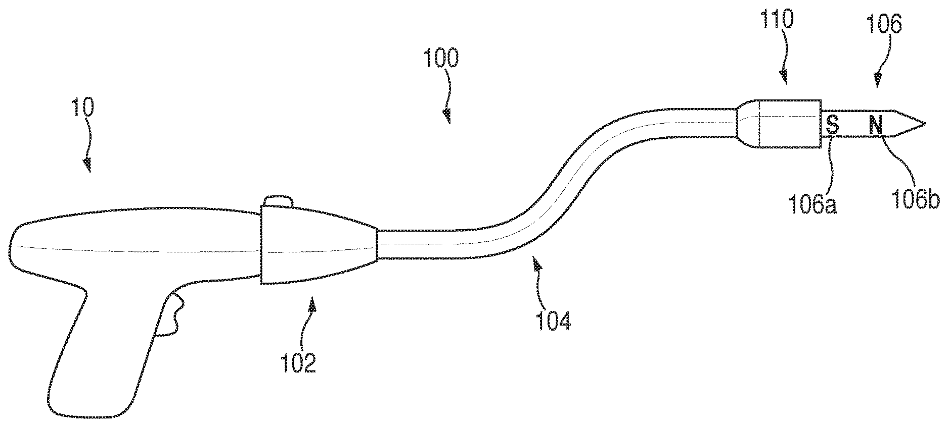
The adapter assembly 100 releasably connects to the powered handle assembly 10. The adapter assembly 100 includes a housing 102 operably connectable to the powered handle assembly 10, and an elongate body 104 extending from the housing 102. A loading unit 110 may be integrated with the adapter assembly 100, or may be releasably coupled to the adapter assembly 100 to permit reuse of the adapter assembly 100. The elongate body 104 is flexible to facilitate insertion of the loading unit 110 within the body.
A trocar member 106 extends from a distal end of the elongate body 104 for releasably engaging an anvil assembly, i.e., anvil assembly 120 (FIG. 2). As shown, a proximal portion 106a of the trocar member 106 includes a first magnetic polarity, i.e., south "5", and a distal portion 106b of the trocar member 106 includes a second magnetic polarity, i.e., north "N". As will become apparent from the below description, the polarities of the proximal and distal portions 106a, 106b of the trocar member 106 may be switched.
With reference to FIG. 2, the anvil assembly 120 is configured for releasable connection to the trocar member 106 (FIG. 1) of the adapter assembly 100 (FIG. 1). The anvil assembly 120 will only be described to the extent necessary to fully disclose the aspects of the present disclosure. For a detailed description of an exemplary anvil assembly, please refer to commonly owned U.S. Pat. No. 7,364,060 ("the '060 patent"). Another example of a tiltable anvil assembly is disclosed in commonly owned U.S. Pat. No. 8,540,132 ("the '132 patent"). The content of each of the '060 patent and the '132 patent are incorporated herein by reference in their entirety.
Briefly, the anvil assembly 120 includes a center rod assembly 122, and an anvil head assembly 124 secured to the center rod assembly 122. The head assembly 124 of the anvil assembly 120 may be rigidly secured to the center rod assembly 122. Alternatively, the head assembly 124 may be pivotally secured to the center rod assembly 122 to facilitate insertion of the anvil assembly 120 through a lumen of a patient. The center rod assembly 122 of the anvil assembly 120 includes a center rod 126. In one embodiment, the center rod 126 is magnetized. As shown in FIG. 2, the center rod 126 includes a proximal portion 126a with a first magnetic polarity, i.e., south "S", and a distal portion 126b with a second magnetic polarity, i.e., north "N".
As noted above, the trocar member 106 (FIG. 1) of the adapter assembly 100 (FIG. 1) is magnetized in a similar manner to the center rod 126 of the anvil assembly 120. In this manner, the proximal portion 126a of the center rod 126 of the anvil assembly 120 is attracted to the distal portion 106b of the trocar member 106.
During a surgical stapling procedure, the anvil assembly 120 may be introduced to a surgical site trans-orally, or in any other manner. After securing a first section of tissue to be stapled (not shown) to the anvil assembly 120, and after securing a second section of tissue to be stapled (not shown) about the loading unit 110 of the adapter assembly 100, the adapter assembly 100 is moved towards the anvil assembly 120. The magnetic attraction between the proximal portion 126a of the center rod 126 of the anvil assembly 120 and the distal portion 106b of the trocar member 106 facilitates alignment of the center rod 126 of the anvil assembly 120 with the trocar member 106 of the adapter assembly 100. This feature is particularly beneficial when the anvil assembly 120 is not visible to the clinician during connection of the anvil assembly 120 to the adapter assembly 100.
Turning to FIG. 3, in an alternative embodiment, the anvil assembly 120 includes a removable tip member 130 for facilitating receipt of the center rod 126 of the anvil assembly 120 through tissue (not shown). The removable tip member 130 includes a proximal portion 130a configured for piercing tissue and a distal end 130b configured for operable connection to the proximal end 126a of the center rod 126. The proximal portion 130a of the removable tip member 130 includes a first magnetic polarity, i.e., south "S", and the distal portion 130b of the removable tip member 130 includes a second magnetic polarity, i.e., north "N". When the removable tip member 130 is secured to the center rod 126 of the anvil assembly 120, in a manner similar to the magnetized center rod 126 described above, the magnetic attraction between the proximal portion 130a of the removable tip member 130 and the distal portion 106b (FIG. 1) of the trocar member 106 (FIG. 1) of the adapter assembly 100 (FIG. 1) facilitates approximation of the anvil assembly 120 to the adapter assembly 100.
Turning now to FIG. 4, an alternative embodiment of an adapter assembly according to the present disclosure is shown generally as adapter assembly 200. The adapter assembly 200 is substantially similar to adapter assembly 100 described hereinabove. The adapter assembly 200 includes a housing 202, an elongate body 204 extending from the housing 202, a trocar member 204 extending from the elongate body 204 for releasably securing an anvil assembly, e.g., anvil assembly 120 (FIG. 2), and a loading unit 210 disposed on a distal end of the elongate body 204.
With continued reference to FIG. 4, the adapter assembly 200 includes an electromagnet assembly 240. The electromagnet assembly 240 includes a wire coil or solenoid, 242 disposed within the loading unit 210 of the adapter assembly 200 and about the trocar member 206. The wire coil 242 is connected to a power source 244. The power source 244 may be disposed within the housing 202 of the adapter assembly 200, within the handle assembly 10 (FIG. 1), as a standalone power source, or in any other suitable configuration. A switch 246 for activating the electromagnet assembly 240 may be disposed on the housing 202 of the adapter assembly 200, as shown, or may be disposed on the handle assembly 10 (FIG. 1), or as an independent actuator i.e., foot pedal (not shown).
Activation of the electromagnet assembly 240 of the adapter assembly 200 magnetizes the trocar member 206. As described above with regards to the trocar member 106 of the adapter assembly 100, when the trocar member 206 of the adapter assembly 200 is magnetized, an anvil assembly that includes a magnetized portion, i.e., the center rod 126, the removable trocar tip 130, is attracted to the trocar member 206 to facilitate connection of the anvil assembly to the trocar member 206.
With reference now to FIGS. 5 and 6, an instrument for facilitating positioning of a magnetized anvil assembly, i.e., the anvil assembly 120, within a patient is shown generally as insertion instrument 300. The insertion instrument 300 includes a handle assembly 302, and an elongate body 304 extending from the handle assembly 302. The insertion instrument 300 also includes an electromagnet assembly 340 and a light assembly 350.
The electromagnet assembly 340 is similar to the electromagnet assembly 240 of the adapter assembly 200, and includes a wire coil 342 wrapped about a ferromagnetic material, i.e., rod member 348, a power source 344 connected to the wire coil 342, and an activation switch 346 for activating the electromagnet assembly 340.
The light assembly 350 includes at least one light source, for example, a circular array of light emitting diodes 352 mounted on a distal end of the elongate body 304, and a control switch for activating the light source 352 and for controlling the intensity of the light source 352. The light source 352 may be powered by the power source 344 of the electromagnet assembly 340. Alternatively, the light source 352 may be powered by an independent power source disposed within the handle assembly 302.
During positioning of the anvil assembly 120, activation of the electromagnet assembly 340 of the insertion instrument 300 creates a magnetic field that attracts the magnetized center rod 126 (FIG. 2) of the anvil assembly 120 to facilitate positioning of the anvil assembly 120 within the body cavity and through tissue "T". Activation of the light source 352 of the light assembly 352 facilitates viewing of the anvil assembly 120 as the anvil assembly 120 is positioned through the tissue "T". It is envisioned that the light source 352 may be placed behind the tissue "T" to illuminate the tissue "T".
With reference now to FIG. 7, an assembly for protecting the elongate body 104 of the adapter assembly 100 and the loading unit 110 that is secured to the elongate body 104, and for minimizing damage to tissue of a patient during introduction of the adapter assembly 100 within the patient, is shown generally as protective assembly 400. The protective assembly 400 includes a sleeve member 402, and an insufflation port 404 operably connected to the sleeve member 402. The insufflation port 404 may include a luer connector or other suitable connection. The protective assembly 400 further includes a syringe 406 or other source of insufflation fluid, i.e., air canister, bellow pump, configured for operable connection with the insufflation port 404.
With additional reference to FIG. 8, the sleeve member 402 of the protective assembly 400 includes an elongate flexible body 410 configured to be received about the elongate body 104 (FIG. 7) of the adapter assembly 100 (FIG. 7) and the loading unit 110 (FIG. 7) that is secured to the elongate body 102 of the adapter assembly. The sleeve member 402 includes open proximal and distal ends 402a, 402b, and defines an inflatable annular cavity or donut 403 extending about the open distal end 402b in fluid communication with the insufflation port 404. As will be described in further detail below, the inflatable donut 403 is configured to be positioned adjacent the distal end of the elongate body 104 for protecting the adapter assembly 100 from damage during introduction of the adapter assembly 100 into a patient, and for protecting the tissue of the patient. The inflatable donut 403 is connected to the insufflation port 404 by one or more inflation channels 405 extending along the length of the elongate flexible body 410 of the sleeve member 402.
The open proximal end 402a of the sleeve member 402 includes a handle member or pull back handle 408 for facilitating receipt of the sleeve member 402 about the elongate body 104 of the adapter assembly 100, and for facilitating removal of the sleeve member 402 from about the elongate body 104. The sleeve member 402 may include a perforation or tear-line 412 extending along all or a portion of the length of the elongate flexible body 410. Alternatively, the sleeve member 402 may by formed of a sheet of material having a hook and loop type fastener (e.g., Velcro.RTM.), or zip lock connection, for maintaining the tubular structure.
During a surgical procedure, and prior to introduction of the elongate body 104 of the adapter assembly 100 into a patient, the sleeve member 402 of the protective assembly 400 is received about the elongate body 104. The sleeve member 402 of the protective assembly 400 may be received about the elongate body 102 when the sleeve member 402 is in an inflated configuration (FIG. 9A), or when sleeve member 402 is in a deflated configuration (FIG. 9B). The sleeve member 402 is retracted about the elongate body 402 until the inflatable annular cavity 403 is disposed adjacent the distal end of the elongate body 104. If the inflatable annular cavity 403 of the sleeve member 402 is not already inflated, the syringe 406 (FIG. 7) may be used to inflate the inflatable annular cavity 403.
During introduction of the elongate body 104 of the adapter assembly 100 into a patient, the sleeve member 402 of the protective assembly 400 protects the distal end of the elongate body 104 from damage, while also protecting the tissue through which the adapter assembly 100 is introduced. Once the adapter assembly 100 has been positioned within the patient, the inflatable annular cavity 403 of the sleeve member 402 of the protective assembly 400 may be deflated to facilitate removal of the sleeve member 402 from the elongate body 104 of the adapter assembly 100. As noted above, the sleeve member 402 may include perforation or tear-line 412 for facilitating removal of the sleeve member 402 from about the elongate body 104. Once the sleeve member 402 of the protective assembly 400 is removed from about the elongate body 104 of the adapter assembly 100, the adapter assembly 100 may be used in a traditional manner.
With reference now to FIGS. 10-12, another embodiment of an assembly for protecting the elongate body 104 of the adapter assembly 100 and the loading unit 110 that is secured to the elongate body 104, and for minimizing damage to tissue of a patient during introduction of the adapter assembly 100 within the patient, is shown generally as protective assembly 500. The protective assembly 500 includes a sleeve member 502, and a cap member 504 secured to a distal end of the sleeve member 502. The sleeve member 502 is configured to be received about the elongate body 104 of adapter assembly 100. The cap member 504 is configured to be releasably received about the loading unit 110 secured to the distal end of the elongate body 104 of the adapter assembly 100.
The sleeve member 502 of the protective assembly 500 is substantially similar to sleeve member 402 of the protective assembly 400 described above, and includes an elongate flexible body 506. As shown, the cap member 504 includes a substantially conical shape and may be transparent or translucent. The cap member 504 is formed of flexible plastic or other suitable material, and is divided into multiple leaves or sections 504a. For example, and as shown, the cap member 504 includes two leaves (FIG. 11A), three leaves (FIG. 11B), four leaves (FIG. 11C), or five leaves (FIG. 11D). The leaves 504a may be connected by a frangible connection 504b, e.g., weakened plastic bridges, which are configured to break during retraction of the sleeve member 502 relative to the elongate body 104 of the adapter assembly 100. The greater number of leaves 504a, the less room the cap member 504 will occupy radially as the protective assembly 500 is removed from about the elongate body 104 of the adapter assembly 100.
The elongate flexible body 506 of the sleeve member 502 may be constructed of a more flexible material than the cap member 504. The cap member 504 may be made more rigid by increasing the wall thickness of the leaves 504a or by using a stiffer material to construct the cap member 504.
As shown in FIG. 12, removal of the protective assembly 500 from about the elongate body 104 of the adapter assembly 100 requires pulling handle members 508 proximally and radially outward relative to the elongate body 104, as indicated by arrows "A", to cause tearing of the sleeve member 502 along a tear-line 512 and to cause separation of the leaves 504a of the cap member 504. As the sleeve member 502 is separated along the tear-line 512 and the sleeve member 502 is retracted proximally relative to the elongate body 104, the leaves 504a of the cap member 504 separate to permit passage of the loading unit 110 therethrough. Once completely removed from about the elongate body 104 of the adapter assembly 100, the clinician may dispose of the protective assembly 500, and the adapter assembly 100 may be used in a traditional manner.
Turning to FIGS. 13-15, another embodiment of an assembly for protecting the elongate body 104 of the adapter assembly 100 and an attached loading unit 110, is shown generally as protective assembly 600. The protective assembly 600 includes a sleeve member 602, and a cap member 604 secured to a distal end of the sleeve member 602. The protective assembly 600 further includes a camera assembly 606 supported within the cap member 604. The camera assembly 606 may connect with a monitoring unit (not shown) wirelessly, or through a wire "W" (FIG. 15) extending along the length of the sleeve member 602.
The cap member 604 includes a plurality of leaves 604a. The camera assembly 606 is supported on a distal end of one of the leaves 604a. The camera assembly 606 may be removable to permit reuse. The camera assembly 606 permits viewing as the elongate body 104 of the adapter assembly 100 is introduced into a patient. The camera assembly 606 may include charge-coupled device (CCD) cameras, or other suitable cameras.
With reference now to FIGS. 16 and 17, an assembly for protecting the elongate body 104 of the adapter assembly 100 and a loading unit 110 attached to the elongate body 104, is shown generally as protective assembly 700. The protective assembly 700 is substantially similar to protective assemblies 400, 500, 600 described hereinabove. The protective assembly 700 includes a sleeve member 702, a cap member 704 integrally formed with or secured to a distal end of the sleeve member 702, and a steering assembly 706 supported on and extending through the sleeve member 702.
The steering assembly 706 includes a steering ring 708, and a plurality of steering cables 710 extending from the steering ring 708 and through the sleeve member 702. The steering cables 710 are each received through a lumen 705 of the sleeve member 702. As shown, the protective assembly 700 includes four (4) steering cables 710. However, it is envisioned that the protective assembly 700 may have more or less than four (4) steering cables 710.
During a surgical procedure, after the protective assembly 700 is received about the elongate body 104 of the adapter assembly 100, the steering ring 708 may be used to guide the elongate body 104 of the adapter assembly 100 within a patient. More particularly, rotation of the steering ring 708 of the protective assembly 700 about a longitudinal axis of the adapter assembly 100, as indicated by arrows "B" in FIG. 16, causes corresponding movement of the sleeve member 702 of the protective assembly 700 which moves the elongate body 104 of the adapter assembly 100. As the adapter assembly 100 is being introduced into a patient, rotation of the steering ring 708 relative to the adapter assembly 100 facilitates continued movement of the adapter assembly 100 to the desired position.
With reference now to FIG. 18, an assembly for protecting the loading unit 110 secured to the distal end of the elongate body 104 of the adapter assembly 100 is shown generally as protective assembly 800. The protective assembly 800 includes an inflatable member 802 configured for operable engagement of the loading unit 110, and an insufflation port 804 for effecting insufflation of the inflatable member 802. The insufflation port 804 may include a luer connector, or other suitable connection means, and is in fluid communication with the inflatable member 802 through an inflation tube 804a. The protective assembly 800 may further include a syringe, canister, bellow, or other suitable means for inflating the inflatable member 802.
The inflatable member 802 of the protective assembly has a first substantially spherical portion 802a, and a second substantially spherical portion 802b extending from the first substantially spherical portion 802a. The first substantially spherical portion 802a being greater in size or diameter than the second substantially spherical portion 802b when the inflatable member 802 is in an inflated condition. As shown in FIG. 18, when the inflatable member 802 is in the inflated condition, the second substantially spherical portion 802b is securely received within a cylindrical cavity 111 of the loading unit 110 which is secured to the distal end of the elongate body 104 of the adapter assembly 100. When the second substantially spherical portion 802b of the inflatable member 802 is received within the cylindrical cavity 111 of the loading unit 110, the first substantially spherical portion 802a covers a distal end of the loading unit 110. In this manner, the inflatable member 802 prevents contact of the distal end of the loading unit 110 with tissue as the adapter assembly 100 and the attached protective assembly 800 is introduced within a patient.
It is envisioned that the first substantially spherical portion 802a of the inflatable member 802 may be configured to match the contour of the loading unit 110. In this manner, the inflatable member 802 more closely aligns with the loading unit 110.
With reference now to FIGS. 19-21, an embodiment of a loading unit according to the present disclosure is shown generally as loading unit 910. The loading unit 910 is configured for operable connection to the distal end of the elongate body 104 (FIG. 1) of the adapter assembly 100 (FIG. 1). Briefly, the loading unit 910 includes a shell 912 and a cartridge assembly 914 mounted on a distal end of the shell 912. The shell 912 defines a lumen 915 extending therethrough for providing a pathway through the cartridge assembly 914. The lumen 915 may be used to, for example, provide irrigation fluids "I" (FIG. 21) to the tissue being stapled "T". In addition, the lumen 915 may be used to receive, for example, guide wires, scopes "S" (FIG. 20), or other suitable instruments during a stapling procedure. A connector sleeve 916 may be received on a proximal end of the lumen 915 to facilitate receipt of a fluid and/or instrument into and through the lumen.
It is envisioned that the embodiments of the present disclosure may be modified for use with various electromechanical surgical instruments and/or electrosurgical instruments. It is further envisioned that these instruments may, for example, be configured to be detachably coupleable and controllable by a robotic surgical system.
With reference now to FIG. 22, an exemplary robotic surgical system is shown generally as robotic surgical system 1 and, may include a plurality of surgical robotic arms, e.g., surgical robotic arms 2, 3, each having an instrument drive unit, e.g., instrument drive unit 11, 12, and an end effector, e.g., surgical stapler 21, 22, removably attached thereto; a control device, e.g., control device 5; and an operating console, e.g., operating console 4, coupled with the control device 5. As shown, the robotic surgical system 1 is configured for use on a patient "P" lying on a surgical table "ST" to be treated in a minimally invasive manner by means of the surgical stapler 21, 22.
For a detailed description of the construction and operation of an exemplary robotic surgical system, reference may be made to U.S. Patent Application Publication No. 2012/0116416, the entire contents of which are incorporated by reference herein.
Persons skilled in the art will understand that the devices and methods specifically described herein and illustrated in the accompanying drawings are non-limiting exemplary embodiments. It is envisioned that the elements and features illustrated or described in connection with one exemplary embodiment may be combined with the elements and features of another without departing from the scope of the present disclosure. As well, one skilled in the art will appreciate further features and advantages of the disclosure based on the above-described embodiments. Accordingly, the disclosure is not to be limited by what has been particularly shown and described, except as indicated by the appended claims.
* * * * *
D00000
D00001
D00002
D00003
D00004
D00005
D00006
D00007
D00008
D00009
D00010
D00011
D00012

D00013

XML
uspto.report is an independent third-party trademark research tool that is not affiliated, endorsed, or sponsored by the United States Patent and Trademark Office (USPTO) or any other governmental organization. The information provided by uspto.report is based on publicly available data at the time of writing and is intended for informational purposes only.
While we strive to provide accurate and up-to-date information, we do not guarantee the accuracy, completeness, reliability, or suitability of the information displayed on this site. The use of this site is at your own risk. Any reliance you place on such information is therefore strictly at your own risk.
All official trademark data, including owner information, should be verified by visiting the official USPTO website at www.uspto.gov. This site is not intended to replace professional legal advice and should not be used as a substitute for consulting with a legal professional who is knowledgeable about trademark law.