Indoor unit of air-conditioning device having louver with water absorber
Ishikawa , et al.
U.S. patent number 10,591,181 [Application Number 15/765,598] was granted by the patent office on 2020-03-17 for indoor unit of air-conditioning device having louver with water absorber. This patent grant is currently assigned to Mitsubishi Electric Corporation. The grantee listed for this patent is Mitsubishi Electric Corporation. Invention is credited to Masato Ishikawa, Masahide Kinami, Akimoto Suzuki, Kiyoshi Yasutomi.


| United States Patent | 10,591,181 |
| Ishikawa , et al. | March 17, 2020 |
Indoor unit of air-conditioning device having louver with water absorber
Abstract
A highly reliable indoor unit of an air-conditioning apparatus prevents condensation water from dripping from an end portion of an up-down airflow direction louver on the downstream side of an airflow. There are provided a casing having an air inlet and an air outlet and including a heat exchanger and an air-sending fan inside the casing; and an up-down airflow direction louver that is disposed at the air outlet and controls the up-down direction of air from the air outlet. The airflow direction louver includes first and second plates joined together and a water absorber at an end portion of the airflow direction louver on the downstream side of the airflow that passes along the airflow direction louver. The water absorber is held between the first and second plates. A portion of the water absorber is exposed.
| Inventors: | Ishikawa; Masato (Tokyo, JP), Suzuki; Akimoto (Tokyo, JP), Kinami; Masahide (Tokyo, JP), Yasutomi; Kiyoshi (Tokyo, JP) | ||||||||||
|---|---|---|---|---|---|---|---|---|---|---|---|
| Applicant: |
|
||||||||||
| Assignee: | Mitsubishi Electric Corporation
(Tokyo, JP) |
||||||||||
| Family ID: | 58796594 | ||||||||||
| Appl. No.: | 15/765,598 | ||||||||||
| Filed: | December 3, 2015 | ||||||||||
| PCT Filed: | December 03, 2015 | ||||||||||
| PCT No.: | PCT/JP2015/084077 | ||||||||||
| 371(c)(1),(2),(4) Date: | April 03, 2018 | ||||||||||
| PCT Pub. No.: | WO2017/094174 | ||||||||||
| PCT Pub. Date: | June 08, 2017 |
Prior Publication Data
| Document Identifier | Publication Date | |
|---|---|---|
| US 20190078804 A1 | Mar 14, 2019 | |
| Current U.S. Class: | 1/1 |
| Current CPC Class: | F24F 13/14 (20130101); F24F 13/22 (20130101) |
| Current International Class: | F24F 13/14 (20060101); F24F 13/22 (20060101) |
| S64-053844 | Apr 1989 | JP | |||
| H06-137660 | May 1994 | JP | |||
| 2002-156130 | May 2002 | JP | |||
| 2005-121306 | May 2005 | JP | |||
| 2009-063275 | Mar 2009 | JP | |||
Other References
|
International Search Report of the International Searching Authority dated Mar. 1, 2016 for the corresponding International application No. PCT/JP2015/084077 (and English translation). cited by applicant . Office Action dated Apr. 9, 2019 issued in corresponding JP patent application No. 2017-553580 (and English translation). cited by applicant . Office Action dated Jul. 24, 2019 issued in corresponding CN patent application No. 201580057235.7 (and English translation). cited by applicant. |
Primary Examiner: Martin; Elizabeth J
Attorney, Agent or Firm: Posz Law Group, PLC
Claims
The invention claimed is:
1. An indoor unit of an air-conditioning apparatus, the indoor unit comprising: a casing having an air inlet and an air outlet and including a heat exchanger and an air-sending fan disposed inside the casing; and an up-down airflow direction louver disposed at the air outlet and controlling up-down airflow direction of air discharged from the air outlet, the up-down airflow direction louver including a first plate and a second plate joined to each other and a water absorber at an end portion of the up-down airflow direction louver on a downstream side of an airflow that passes along the up-down airflow direction louver, wherein an end portion of the second plate on the downstream side is positioned on the downstream side of the airflow of an end portion of the first plate on the downstream side, and the water absorber is held between the first plate and the second plate, the water absorber includes an exposed portion of a water absorption surface of the water absorber exposed between: a covered portion of the water absorber held between the first plate and the second plate, and an end portion of the second plate on the downstream side.
2. The indoor unit of the air-conditioning apparatus of claim 1, wherein the up-down airflow direction louver includes a hollow space between the first plate and the second plate joined to each other.
3. The indoor unit of the air-conditioning apparatus of claim 1, wherein at least a portion of a surface of the water absorber opposite to the water absorption surface thereof is bonded to one of the first plate and the second plate.
4. The indoor unit of the air-conditioning apparatus of claim 1, wherein during a cooling operation of the indoor unit, the up-down airflow direction louver comes into contact with warm indoor air on a side of the first plate and comes into contact with cool air on a side of the second plate that is heat exchanged by passing through the casing, and a portion of the water absorption surface of the water absorber is exposed to the warm indoor air.
Description
CROSS REFERENCE To RELATED APPLICATION
This application is a U.S. national stage application of PCT/JP2015/084077 filed on Dec. 3, 2015, the contents of which are incorporated herein by reference.
TECHNICAL FIELD
The present invention relates to an indoor unit of an air-conditioning apparatus, the indoor unit including an up-down airflow direction louver that controls an up-down direction of air from an air outlet.
BACKGROUND ART
An indoor unit of an air-conditioning apparatus includes components, such as a heat exchanger and an air-sending fan, inside the indoor unit and also includes an up-down airflow direction louver that controls the blowing direction of heat-exchanged air.
While the air-conditioning apparatus is performing cooling operation, the up-down airflow direction louver is in contact with heat-exchanged cool air and with air that contains indoor moisture and is still warm. In the above circumstance, condensation due to a temperature difference easily occurs on the up-down airflow direction louver.
Therefore, an up-down airflow direction louver to which a thermal insulation material is bonded is known. A method of preventing condensation by causing cool air to flow along both sides of front and back surfaces of an up-down airflow direction louver is also known.
In addition, a technique that prevents condensation by thermal insulation by providing a hollow layer between two stacked components of an up-down airflow direction louver, which is divided into two as the two components at the front and the back, is known (refer to, for example, Patent Literature 1).
CITATION LIST
Patent Literature
Patent Literature 1: Japanese Unexamined Patent Application Publication No. 2009-63275
SUMMARY OF INVENTION
Technical Problem
In the technique in Patent Literature 1, the up-down airflow direction louver is divided into two as the front and back components, and the two components are stacked with the hollow layer provided therebetween for thermal insulation. Thus, even when heat-exchanged cool air is blown onto one surface of the up-down airflow direction louver, the other surface of the up-down airflow direction louver in contact with indoor air is not cooled.
However, there is a drawback in which condensation easily occurs due to the indoor air that comes into contact with an end portion of the up-down airflow direction louver on the downstream side of an airflow that passes along the up-down airflow direction louver.
To solve the above drawback, the present invention provides a highly reliable indoor unit of an air-conditioning apparatus that prevents condensation water from dripping from an end portion of an up-down airflow direction louver on the downstream side of an airflow.
Solution to Problem
An indoor unit of an air-conditioning apparatus according to an embodiment of the present invention includes a casing having an air inlet and an air outlet and including a heat exchanger and an air-sending fan disposed inside the casing; and an up-down airflow direction louver that is disposed at the air outlet and controls an up-down direction of air from the air outlet. The up-down airflow direction louver includes a first plate and a second plate joined to each other and includes a water absorber at an end portion of the up-down airflow direction louver on the downstream side of an airflow that passes along the up-down airflow direction louver. The water absorber is held between the first plate and the second plate. A portion of the water absorber is exposed.
Advantageous Effects of Invention
The indoor unit of the air-conditioning apparatus according to an embodiment of the present invention includes the water absorber at the end portion on the downstream side of the airflow that passes along the up-down airflow direction louver. The water absorber is held between the first plate and the second plate. The portion of the water absorber is exposed. Due to such a structure, even when condensation occurs on the end portion of the up-down airflow direction louver on the downstream side, condensation water can be retained by the water absorber and prevented from dripping in a room.
Moreover, because the water absorber is held between the first plate and the second plate, the water absorber does not come off from the up-down airflow direction louver, which leads to high durability and high reliability.
Therefore, it is possible to provide the highly reliable indoor unit of the air-conditioning apparatus that prevents condensation water from dripping from the end portion of the up-down airflow direction louver on the downstream side of the airflow.
BRIEF DESCRIPTION OF DRAWINGS
FIG. 1 is a top perspective view of an indoor unit of an air-conditioning apparatus according to Embodiment 1 of the present invention.
FIG. 2 is a bottom perspective view of the indoor unit of the air-conditioning apparatus according to Embodiment 1 of the present invention.
FIG. 3 is a sectional view of the indoor unit of the air-conditioning apparatus according to Embodiment 1 of the present invention during non-operation.
FIG. 4 is a sectional view of the indoor unit of the air-conditioning apparatus according to Embodiment 1 of the present invention during cooling operation.
FIG. 5 is a sectional view of a second up-down airflow direction louver according to Embodiment 1 of the present invention.
FIG. 6 is a sectional view of a third up-down airflow direction louver according to Embodiment 1 of the present invention.
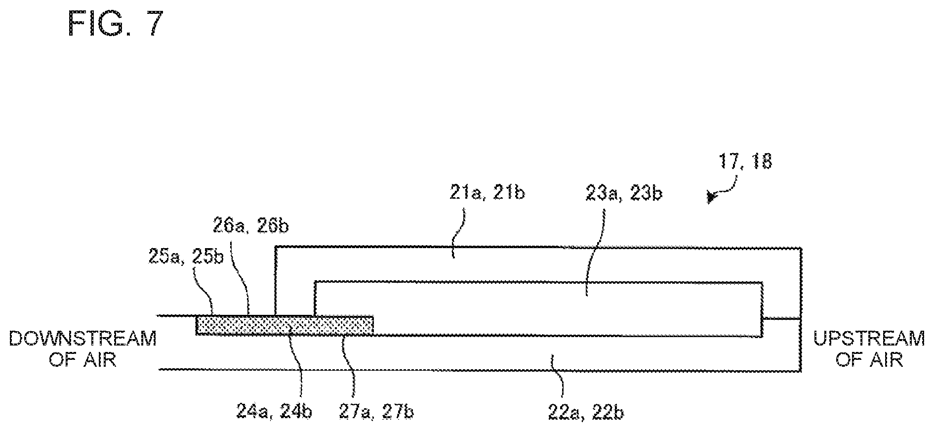
FIG. 7 illustrates an outline of the structure of the second up-down airflow direction louver and the third up-down airflow direction louver according to Embodiment 1 of the present invention.
DESCRIPTION OF EMBODIMENTS
An embodiment of the present invention will be described below on the basis of the drawings.
It is to be noted that in the drawings, components that are given the same reference character are identical or correspond to each other; the same applies to the whole text of the description.
In addition, the form of each component described in the whole text of the description is merely an example, and the form of each component is not limited by these descriptions.
Embodiment 1
FIG. 1 is a top perspective view of an indoor unit 100 of an air-conditioning apparatus according to Embodiment 1 of the present invention. FIG. 2 is a bottom perspective view of the indoor unit 100 of the air-conditioning apparatus according to Embodiment 1 of the present invention. FIG. 3 is a sectional view of the indoor unit 100 of the air-conditioning apparatus according to Embodiment 1 of the present invention during non-operation. FIG. 4 is a sectional view of the indoor unit 100 of the air-conditioning apparatus according to Embodiment 1 of the present invention during cooling operation.
The indoor unit 100 of the air-conditioning apparatus includes an inverter-driven compressor, a four-way valve, a condensation-side heat exchanger, a decompressor, and an evaporation-side heat exchanger, which are connected to each other. The inverter-driven compressor is controllable in terms of rotation speed. The indoor unit 100 is a wall-hung type indoor unit capable of performing cooling operation and heating operation by switching the four-way valve.
As illustrated in FIGS. 1 to 4, the indoor unit 100 of the air-conditioning apparatus includes a back surface case 2 constituting a casing 1 of the indoor unit 100, a front surface panel 3 constituting the casing 1 of the indoor unit 100, a suction grille 4 constituting the casing 1 of the indoor unit 100 and serving as an aesthetic surface, and side covers 5 constituting the casing 1 of the indoor unit 100.
A heat exchanger 6 having a bent shape, an air-sending fan 7 positioned downstream of an airflow of the heat exchanger 6, and an electrical item box (not shown) are attached to the back surface case 2. A drain pan 8 that receives condensation water from the heat exchanger 6 is disposed below the heat exchanger 6 on a front surface side. An air outlet 9 for blowing out heat-exchanged air is disposed below the air-sending fan 7.
The front surface panel 3 constitutes an upper surface portion and a front surface portion of the casing 1 of the indoor unit 100. An upper air inlet 10 is formed in an upper surface of the front surface panel 3. A filter 11 that covers top and front surfaces of the heat exchanger 6 is disposed inside the front surface panel 3. The filter 11 is arranged so as to surround the heat exchanger 6. The front surface panel 3 is fixed to the back surface case 2.
The suction grille 4 constitutes the front surface portion of the casing 1 of the indoor unit 100. The suction grille 4 includes an upper cover 12 positioned at an upper part of a front surface of the casing 1 and a lower cover 13 positioned at a lower part of the front surface of the casing 1. A horizontally extending gap between the upper cover 12 and the lower cover 13 serves as a front surface air inlet 14.
The indoor unit 100 of the air-conditioning apparatus includes a left-right airflow direction louver 15 that is disposed at the air outlet 9 and that controls the direction of air blown out from the air outlet 9 in terms of the left-right direction of a living space. The left-right airflow direction louver 15 may be separated into two as left and right sections to perform air-conditioning of two places. The left-right airflow direction louver 15 can be turned by a drive motor (not shown).
The indoor unit 100 of the air-conditioning apparatus includes a first up-down airflow direction louver 16, a second up-down airflow direction louver 17, and a third up-down airflow direction louver 18 that are disposed at the air outlet 9 and that control the direction of the air blown out from the air outlet 9 in terms of the up-down direction, which is the height direction of the living space.
The first up-down airflow direction louver 16 is formed of a curved plate member. The first up-down airflow direction louver 16 is positioned between the second up-down airflow direction louver 17 and the third up-down airflow direction louver 18 during operation. The second up-down airflow direction louver 17 is disposed on a back surface side of the air outlet 9. The third up-down airflow direction louver 18 is disposed on a front surface side of the air outlet 9. The third up-down airflow direction louver 18 is smaller than the second up-down airflow direction louver 17. Details of the structures of the second up-down airflow direction louver 17 and the third up-down airflow direction louver 18 will be described later. The first up-down airflow direction louver 16, the second up-down airflow direction louver 17, and the third up-down airflow direction louver 18 can be turned by the drive motor (not shown).
The indoor unit 100 of the air-conditioning apparatus suctions indoor air through the upper air inlet 10 and the front surface air inlet 14 by using the air-sending fan 7. The air suctioned into the indoor unit 100 is heat exchanged by the heat exchanger 6 and becomes cool air or warm air. The cool air or the warm air is blown into a room through the air outlet 9, at which the left-right airflow direction louver 15, the first up-down airflow direction louver 16, the second up-down airflow direction louver 17, and the third up-down airflow direction louver 18 are disposed.
At this time, the left-right airflow direction louver 15 turns to control the left-right direction of the heat-exchanged air blown by the air-sending fan 7. The first up-down airflow direction louver 16, the second up-down airflow direction louver 17, and the third up-down airflow direction louver 18 also turn to control the up-down direction of the heat-exchanged air blown by the air-sending fan 7.
The indoor unit 100 of the air-conditioning apparatus also includes an infrared sensor 19 that is positioned next to the air outlet 9 in the left-right direction and that measures a temperature of a floor, a temperature of a wall surface, a position of a human body, and an active state of the human body in the room.
It is to be noted that a structure that includes a cross flow fan, as the air-sending fan 7, on the downstream side of the heat exchanger 6 is described herein; however, the structure may include a different fan, for example, a propeller fan. In addition, the structure may include a different fan, for example, a propeller fan, on the upstream side of the heat exchanger.
Next, an outline of the structure of the second up-down airflow direction louver 17 and the third up-down airflow direction louver 18 will be described.
FIG. 5 is a sectional view of the second up-down airflow direction louver 17 according to Embodiment 1 of the present invention. FIG. 6 is a sectional view of the third up-down airflow direction louver 18 according to Embodiment 1 of the present invention. FIG. 7 illustrates an outline of the structure of the second up-down airflow direction louver 17 and the third up-down airflow direction louver 18 according to Embodiment 1 of the present invention.
As illustrated in FIG. 7, the second up-down airflow direction louver 17 is formed by joining a first plate 21a and a second plate 22a to each other so as to be at the front and back, respectively, and the third up-down airflow direction louver 18 is formed by joining a first plate 21b and a second plate 22b to each other so as to be at the front and back, respectively. During operation, the first plate 21a is on the side of a front surface of the second up-down airflow direction louver 17, and the first plate 21b is on the side of a front surface of the third up-down airflow direction louver 18. During operation, the second plate 22a is on the side of a back surface of the second up-down airflow direction louver 17, and the second plate 22b is on the side of a back surface of the third up-down airflow direction louver 18. Hollow parts 23a and 23b are provided inside the second up-down airflow direction louver 17 and the third up-down airflow direction louver 18, respectively. The second up-down airflow direction louver 17 includes a water absorber 24a at an end portion thereof on the downstream side of an airflow that passes along the second up-down airflow direction louver 17, and the third up-down airflow direction louver 18 includes a water absorber 24b at an end portion thereof on the downstream side of an airflow that passes along the third up-down airflow direction louver 18. The water absorbers 24a and 24b are held between the first plate 21a and the second plate 22a and between the first plate 21b and the second plate 22b, respectively. Specifically, the water absorber 24a is held between an end surface at an end portion of the first plate 21a on the downstream side and a plate surface of the second plate 22a, and the water absorber 24b is held between an end surface at an end portion of the first plate 21b on the downstream side and a plate surface of the second plate 22b. The water absorber 24a is in a state of having an exposed portion 25a, where a portion of the water absorber 24a is exposed, and the water absorber 24b is in a state of having an exposed portion 25b, where a portion of the water absorber 24b is exposed.
A resin such as a PS resin or an ABS resin is used to mold the first plates 21a and 21b and the second plates 22a and 22b. The first plates 21a and 21b are joined to the second plates 22a and 22b, respectively, by using a catch (not shown) or by ultrasonic welding, heat welding, or other methods. The first plate 21a and the second plate 22a are not required to be in close contact with each other to cause the hollow part 23a to form a strong thermally insulated state, because the first and second plates 21a and 22a are provided with the hollow part 23a therebetween and hold the water absorber 24a. The first plate 21b and the second plate 22b are also not required to be in close contact with each other to cause the hollow part 23b to form a strong thermally insulated state, because the first and second plates 21b and 22b are provided with the hollow part 23b therebetween and hold the water absorber 24b.
The water absorbers 24a and 24b are formed of, for example, felt or flock. The water absorber 24a has a water absorption surface 26a exposed at the exposed portion 25a at an end portion of the second plate 22a on the downstream side, the end portion positioned on the downstream side of airflow of the end portion of the first plate 21a on the downstream side of airflow. The water absorber 24b has a water absorption surface 26b exposed at the exposed portion 25b at an end portion of the second plate 22b on the downstream side, the end portion positioned on the downstream side of airflow of the end portion of the first plate 21b on the downstream side of airflow. Each of the water absorbers 24a and 24b includes an adhesive material (not shown) or a double-sided tape (not shown) disposed on a back side of the water absorption surface 26a or 26b corresponding thereto. The water absorbers 24a and 24b are bonded to an adhesion surface 27a of the second plate 22a and to an adhesion surface 27b of the second plate 22b, respectively, via the adhesive material or the double-sided tape.
The water absorbers 24a and 24b may be bonded to the first plates 21a and 21b, respectively, instead of to the second plate 22a or 22b.
Next, the second up-down airflow direction louver 17 will be described in detail.
As illustrated in FIG. 5, during cooling operation, the second up-down airflow direction louver 17 comes into contact, on the side of the second plate 22a, with warm indoor air and comes into contact, on the side of the first plate 21a, with cool air that is heat exchanged by passing through the casing 1.
A portion of the water absorption surface 26a of the water absorber 24a is exposed to the side of the cool air on the side of the first plate 21a, the portion being positioned further to the downstream side of the airflow than a portion of the water absorber 24a held between the first plate 21a and the second plate 22a.
A distal end of the end portion of the second plate 22a on the downstream side is curved toward the side of the first plate 21a. The water absorber 24a can be bonded to the second plate 22a along the curved portion, which enables easy bonding of the water absorber 24a.
The distal end of the end portion of the second plate 22a on the downstream side need not be curved toward the side of the first plate 21a.
As illustrated in FIG. 3, the second up-down airflow direction louver 17 closes the air outlet 9 during non-operation and forms an aesthetic surface of a lower surface of the indoor unit 100 of the air-conditioning apparatus. Thus, the water absorption surface 26a of the water absorber 24a is bonded so as to face the side of the first plate 21a. As a result, the water absorber 24a is not exposed during non-operation, which enables the lower surface of the indoor unit 100 to have a simple appearance.
The second up-down airflow direction louver 17 may be formed to be inside-out such that the first plate 21a serves as the surface constituting the aesthetic surface of the lower surface of the indoor unit 100 of the air-conditioning apparatus during non-operation. In this case, the water absorber 24a is exposed on the aesthetic surface of the lower surface of the indoor unit 100 of the air-conditioning apparatus during non-operation.
Next, the third up-down airflow direction louver 18 will be described in detail.
As illustrated in FIG. 6, during cooling operation, the third up-down airflow direction louver 18 comes into contact, on the side of the first plate 21b, with the warm indoor air and comes into contact, on the side of the second plate 22b, with the cool air that is heat exchanged by passing through the casing 1.
A portion of the water absorption surface 26b of the water absorber 24b is exposed to the side of the warm indoor air on the side of the first plate 21b, the portion being positioned further to the downstream side of the airflow than a portion of the water absorber 24b held between the first plate 21b and the second plate 22b. Such a structure enables condensation water generated due to the warm air to be immediately absorbed by the water absorber 24b.
Adhesion surfaces for the water absorber 24b are at two positions, which are at the end portion of the second plate 22b on the downstream side and at a support portion 22b1 that protrudes from the second plate 22b toward the side of the first plate 21a. The water absorber 24b is bonded to the two adhesion surfaces, and the first plate 21b projects over the water absorber 24b.
The second plate 22b may be formed in such a manner that a gap between the end portion of the second plate 22b on the downstream side and the support portion 22b1 is filled with a resin. In addition, the adhesion surface 27b for the water absorber 24b may be on the side of the first plate 21b.
As illustrated in FIG. 3, the third up-down airflow direction louver 18 is stored inside the indoor unit 100 of the air-conditioning apparatus during non-operation.
Due to the second up-down airflow direction louver 17 and the third up-down airflow direction louver 18 having the above structures, when condensation occurs on the end portions on the downstream side of the airflow that passes along the second up-down airflow direction louver 17 and the third up-down airflow direction louver 18, condensation water is retained by the water absorbers 24a and 24b and prevented from dripping in a room.
Moreover, even when adhesives of the water absorbers 24a and 24b peel off, the water absorbers 24a and 24b do not come off from the second up-down airflow direction louver 17 or the third up-down airflow direction louver 18, because the water absorbers 24a and 24b are held between the first plate 21a and the second plate 22a and between the first plate 21b and the second plate 22b, respectively.
According to Embodiment 1 above, the indoor unit 100 of the air-conditioning apparatus includes the casing 1 having the upper air inlet 10, the front surface air inlet 14, and the air outlet 9 and including the heat exchanger 6 and the air-sending fan 7 disposed inside the casing 1. In addition, there are provided the second up-down airflow direction louver 17 and the third up-down airflow direction louver 18, which are disposed at the air outlet 9 and control the up-down direction of the air from the air outlet 9. The second up-down airflow direction louver 17 includes the first plate 21a and the second plate 22a joined to each other, and the third up-down airflow direction louver 18 includes the first plate 21b and the second plate 22b joined to each other. The second up-down airflow direction louver 17 and the third up-down airflow direction louver 18 include the water absorbers 24a and 24b, respectively, which are at the end portions corresponding thereto on the downstream side of the airflow that passes along the second up-down airflow direction louver 17 and the third up-down airflow direction louver 18. The water absorbers 24a and 24b are held between the first plate 21a and the second plate 22a and between the first plate 21b and the second plate 22b, respectively. The portion of the water absorber 24a and the portion of the water absorber 24b are exposed.
In the above structure, there are provided the water absorbers 24a and 24b at the end portions corresponding thereto on the downstream side of the airflow that passes along the second up-down airflow direction louver 17 and the third up-down airflow direction louver 18. The water absorbers 24a and 24b are held between the first plate 21a and the second plate 22a and between the first plate 21b and the second plate 22b, respectively. The portion of the water absorber 24a and the portion of the water absorber 24b are exposed. Due to such a structure, even when condensation occurs on the end portion of the second up-down airflow direction louver 17 on the downstream side or on the end portion of the third up-down airflow direction louver 18 on the downstream side, condensation water can be retained by the water absorber 24a or 24b and prevented from dripping in a room.
Moreover, because the water absorbers 24a and 24b are held between the first plate 21a and the second plate 22a and between the first plate 21b and the second plate 22b, respectively, the water absorbers 24a and 24b do not come off from the second up-down airflow direction louver 17 or from the third up-down airflow direction louver 18, which leads to high durability and high reliability.
Accordingly, it is possible to provide the highly reliable indoor unit 100 of the air-conditioning apparatus, which prevents condensation water from dripping from the end portions of the second up-down airflow direction louver 17 and the third up-down airflow direction louver 18 on the downstream side of the airflow.
The second up-down airflow direction louver 17 is formed by joining the first plate 21a and the second plate 22a to each other and providing the hollow part 23a therebetween, and the third up-down airflow direction louver 18 is formed by joining the first plate 21b and the second plate 22b to each other and providing the hollow part 23b therebetween.
Such a structure improves the heat insulation properties of the second up-down airflow direction louver 17 and the third up-down airflow direction louver 18 due to the hollow parts 23a and 23b, thereby preventing condensation from easily occurring on the end portions on the downstream side of the airflow that passes along the second up-down airflow direction louver 17 and the third up-down airflow direction louver 18.
At least a portion of a surface of the water absorber 24a opposite to the water absorption surface 26a thereof is bonded to one of the first plate 21a and the second plate 22a, and at least a portion of a surface of the water absorber 24b opposite to the water absorption surface 26b thereof is bonded to one of the first plate 21b and the second plate 22b.
In the above structure, the water absorbers 24a and 24b can be fixed by bonding.
During cooling operation, the third up-down airflow direction louver 18 comes into contact, on the side of the first plate 21b, with the warm indoor air and comes into contact, on the side of the second plate 22b, with the cool air that is heat exchanged by passing through the casing 1. The end portion of the second plate 22b on the downstream side is positioned on the downstream side of airflow of the end portion of the first plate 21b on the downstream side of airflow. A portion of the water absorption surface 26b of the water absorber 24b is exposed to the side of the warm indoor air, the portion being positioned further to the downstream side of the airflow than the portion of the water absorber 24b held between the first plate 21b and the second plate 22b.
Due to the above structure, condensation water generated on the side of the warm indoor air can be immediately retained by the water absorption surface 26b of the water absorber 24b.
REFERENCE SIGNS LIST
1 casing 2 back surface case 3 front surface panel 4 suction grille 5 side cover 6 heat exchanger 7 air-sending fan 8 drain pan 9 air outlet 10 upper air inlet 11 filter 12 upper cover 13 lower cover 14 front surface air inlet 15 left-right airflow direction louver 16 first up-down airflow direction louver 17 second up-down airflow direction louver 18 third up-down airflow direction louver 19 infrared sensor 21a first plate 21b first plate 22a second plate 22b second plate 22b1 support portion 23a hollow part 23b hollow part 24a water absorber 24b water absorber 25a exposed portion 25b exposed portion 26a water absorption surface 26b water absorption surface 27a adhesion surface 27b adhesion surface 100 indoor unit
* * * * *
D00000
D00001
D00002
D00003
D00004
D00005
XML
uspto.report is an independent third-party trademark research tool that is not affiliated, endorsed, or sponsored by the United States Patent and Trademark Office (USPTO) or any other governmental organization. The information provided by uspto.report is based on publicly available data at the time of writing and is intended for informational purposes only.
While we strive to provide accurate and up-to-date information, we do not guarantee the accuracy, completeness, reliability, or suitability of the information displayed on this site. The use of this site is at your own risk. Any reliance you place on such information is therefore strictly at your own risk.
All official trademark data, including owner information, should be verified by visiting the official USPTO website at www.uspto.gov. This site is not intended to replace professional legal advice and should not be used as a substitute for consulting with a legal professional who is knowledgeable about trademark law.