Irregular-pitch regenerative blower and optimization design method for same
Lee , et al.
U.S. patent number 10,590,938 [Application Number 15/533,175] was granted by the patent office on 2020-03-17 for irregular-pitch regenerative blower and optimization design method for same. This patent grant is currently assigned to Korea Institute of Industrial Technology. The grantee listed for this patent is KOREA INSTITUTE OF INDUSTRIAL TECHNOLOGY. Invention is credited to Young Seok Choi, Uk Hee Jung, Jin Hyuk Kim, Kyoung-Yong Lee.


View All Diagrams
| United States Patent | 10,590,938 |
| Lee , et al. | March 17, 2020 |
Irregular-pitch regenerative blower and optimization design method for same
Abstract
Provided is a regenerative blower. According to an illustrative embodiment of the present invention, the regenerative blower comprises an impeller comprising a plurality of blades disposed spaced apart in the circumferential direction, wherein, in the plurality of blades, each blade gap is arranged at an incremental angle (.DELTA..THETA.i).
| Inventors: | Lee; Kyoung-Yong (Cheonan-si, KR), Choi; Young Seok (Gwangmyeong-si, KR), Kim; Jin Hyuk (Incheon, KR), Jung; Uk Hee (Cheonan-si, KR) | ||||||||||
|---|---|---|---|---|---|---|---|---|---|---|---|
| Applicant: |
|
||||||||||
| Assignee: | Korea Institute of Industrial
Technology (Cheonan-si, Chungcheongnam-do, KR) |
||||||||||
| Family ID: | 56091988 | ||||||||||
| Appl. No.: | 15/533,175 | ||||||||||
| Filed: | December 2, 2015 | ||||||||||
| PCT Filed: | December 02, 2015 | ||||||||||
| PCT No.: | PCT/KR2015/013040 | ||||||||||
| 371(c)(1),(2),(4) Date: | June 05, 2017 | ||||||||||
| PCT Pub. No.: | WO2016/089103 | ||||||||||
| PCT Pub. Date: | June 09, 2016 |
Prior Publication Data
| Document Identifier | Publication Date | |
|---|---|---|
| US 20170363091 A1 | Dec 21, 2017 | |
Foreign Application Priority Data
| Dec 4, 2014 [KR] | 10-2014-0172727 | |||
| Current U.S. Class: | 1/1 |
| Current CPC Class: | F04D 23/008 (20130101); F04D 29/666 (20130101); F04D 5/002 (20130101); F04D 29/18 (20130101) |
| Current International Class: | F04D 23/00 (20060101); F04D 29/66 (20060101); F04D 5/00 (20060101); F04D 29/18 (20060101) |
References Cited [Referenced By]
U.S. Patent Documents
| 4923365 | May 1990 | Mathias |
| 8092186 | January 2012 | Jang |
| 9599126 | March 2017 | Sagher |
| 2003/0175111 | September 2003 | Miura et al. |
| 2006/0120853 | June 2006 | Narisako et al. |
| 2010/0054949 | March 2010 | Jang et al. |
| 2003-278684 | Oct 2003 | JP | |||
| 2003-336591 | Nov 2003 | JP | |||
| 2006-161723 | Jun 2006 | JP | |||
| 5001975 | Aug 2012 | JP | |||
| 10-0872294 | Dec 2008 | KR | |||
Other References
|
Addison-Wesley, Bradley, Hax, Magnanti, "Applied Mathematical Programming", 1977, MIT, http://web.mit.edu/15.053/www/AppliedMathematicalProgramming.pdf (Year: 1977). cited by examiner. |
Primary Examiner: Wolcott; Brian P
Attorney, Agent or Firm: Rabin & Berdo, P.C.
Claims
What is claimed is:
1. A regenerative blower comprising an impeller including a plurality of blades arranged in a circumferential direction to be spaced part from each other, wherein the plurality of blades are arranged such that angles therebetween are incremental angles .DELTA..THETA.i satisfying the formula: .DELTA..times..times..theta..times..times..function..times..time- s..times..function..times..times. ##EQU00005## wherein Am, P1, and P2 satisfy both relationships 27.ltoreq..eta..ltoreq.32 and 77 dB(A).ltoreq.SPL.ltoreq.83.7 dB(A), wherein .eta.=(P.sub.out-P.sub.in)Q/.sigma..omega., and SPL=10 log.sub.10(P/P.sub.ref).sup.2, where .eta. is efficiency, SPL is a sound pressure level (SPL), (P.sub.out-P.sub.in) is a total pressure, Q is a volumetric flow, .sigma. is a torque, .omega. is an angular velocity, P is a sound pressure, and P.sub.ref is a reference pressure (2.times.10.sup.-5 Pa), wherein N is a total number of the plurality of blades, where N is a natural number greater than 2, Am is a distribution size of distances between the plurality of blades, the plurality of blades being spaced at equal angles, where 0.degree.<Am<360.degree./N, i is a sequence of the plurality of blades, where i=1, 2, 3, 4, . . . , and N, and P1 and P2 are factors having an effect on a period, where 0.ltoreq.P1.ltoreq.N, and 0.ltoreq.P2.ltoreq.N, P1 and P2 being real numbers.
2. The regenerative blower according to claim 1, wherein Am ranges from 1.degree. to 8.23.degree..
3. The regenerative blower according to claim 1, wherein P1 ranges from 1 to 38, and P2 ranges from 0 to 39.
4. A design optimization method for the regenerative blower as claimed in claim 1, the design optimization method comprising: a design variable and objective function selection step; a design area setting step of determining upper and lower limits of design variables; and a step of obtaining optimal solutions for objective functions in the design area, wherein the step of obtaining the optimal solutions for the objective functions in the design area comprises: determining a plurality of test points by Latin hypercube sampling in the design area; and obtaining the objective functions at the plurality of test points by an aerodynamic performance test and a noise test.
5. The design optimization method according to claim 4, further comprising a step of determining whether or not the optimal solutions, obtained in the step of obtaining the optimal solutions for the objective functions in the design area, are proper.
6. The design optimization method according to claim 4, wherein, in the design variable and objective function selection step, the design variables include Am, indicating the distribution size of the distances between the blades, and P1 and P2, indicating the factors having the effect on the period, and the objective functions include .eta., indicating the efficiency, and SPL, indicating the sound pressure level.
7. The design optimization method according to claim 4, wherein, in the design area setting step of determining the upper and lower limits of the design variables, Am ranges from 1 to 8.23, P1 ranges from 1 to 38, and P2 ranges from 0 to 39.
8. The design optimization method according to claim 4, wherein the step of obtaining the optimal solutions for the objective functions in the design area comprises obtaining response surfaces, on which the optimal solutions are to be calculated, using a response surface method.
9. The design optimization method according to claim 8, wherein, when the response surface method is used, a response surface analysis (RSA) model of the objective functions has function types as follows: .eta. is -18.8659-17.9578Am-10.5773P1-21.7493P2+7.3846AmP1+17.3858AmP2-0.789P1P2+6- .2258Am.sup.2+11.0769P1.sup.2+16.1141P2.sup.2, and SPL is 84.2304+4.2557Am-11.8326P1-6.4429P2+8.2626AmP1+4.8169AmP2+5.9802P1P2-4.29- 59Am.sup.2+4.7855P1.sup.2+1.2078P2.sup.2.
10. The design optimization method according to claim 9, wherein, after the step of obtaining the response surfaces, on which the optimal solutions are to be calculated, using the response surface method, the optimal solutions are able to maximize the objective functions, based on the response surfaces of the objective functions obtained by the response surface method, and are obtained using a multi-objective evolutionary algorithm.
11. The design optimization method according to claim 10, wherein, after the optimal solutions able to maximize the objective functions are obtained, more improved values of the optimal solutions are obtained by localized search for the objective functions, using sequential quadratic programming (SQP), which is a gradient-based search algorithm.
12. The design optimization method according to claim 5, wherein the step of determining whether or not the optimal solutions are proper comprises analysis of variance (ANOVA) and regression analysis on response surfaces of the objective functions obtained by a response surface method.
13. A design optimization method for the regenerative blower as claimed in claim 1, the design optimization method comprising: a design variable and objective function selection step; a design area setting step of determining upper and lower limits of design variables; and a step of obtaining optimal solutions for objective functions in the design area.
14. A design optimization method for the regenerative blower as claimed in claim 2, the design optimization method comprising: a design variable and objective function selection step; a design area setting step of determining upper and lower limits of design variables; and a step of obtaining optimal solutions for objective functions in the design area.
15. A design optimization method for the regenerative blower as claimed in claim 3, the design optimization method comprising: a design variable and objective function selection step; a design area setting step of determining upper and lower limits of design variables; and a step of obtaining optimal solutions for objective functions in the design area.
16. A design optimization method for the regenerative blower as claimed in claim 2, the design optimization method comprising: a design variable and objective function selection step; a design area setting step of determining upper and lower limits of design variables; and a step of obtaining optimal solutions for objective functions in the design area, wherein the step of obtaining the optimal solutions for the objective functions in the design area comprises: determining a plurality of test points by Latin hypercube sampling in the design area; and obtaining the objective functions at the plurality of test points by an aerodynamic performance test and a noise test.
17. A design optimization method for the regenerative blower as claimed in claim 3, the design optimization method comprising: a design variable and objective function selection step; a design area setting step of determining upper and lower limits of design variables; and a step of obtaining optimal solutions for objective functions in the design area, wherein the step of obtaining the optimal solutions for the objective functions in the design area comprises: determining a plurality of test points by Latin hypercube sampling in the design area; and obtaining the objective functions at the plurality of test points by an aerodynamic performance test and a noise test.
Description
TECHNICAL FIELD
The present disclosure relates to a regenerative blower and a design optimization method for the same.
BACKGROUND ART
Regenerative blowers are generally used for transferring gas at a relatively low flow-rate and in a relatively high pressure, as in an industrial high-pressure blower (or a ring blower). Recently, the application range thereof is expanding to an air supply of a fuel cell system, a hydrogen recirculation system, and the like.
Such regenerative blowers are divided into an open channel type used as an air supply blower of a system requiring a low flow-rate and a high head and a side channel type. In the regenerative blower, blades are located in the circumferential direction of a disk-shaped rotary impeller. When the regenerative blower operates, internal circulation occurs between the recesses between the blades and the channels of a casing, thereby increasing pressure.
The regenerative blower must have a plurality of blades to raise the head. This consequently forms blade-passing frequencies (BPFs), i.e. high-frequency noise, and nose (overall noise). Although the noise of the regenerative blower can generally be reduced by reducing the number of revolutions by improving efficiency and relative performance, the noise reduction ability is limited.
In addition, when the regenerative blower is used for home and medical uses, a method of reducing noise using a muffler can be used. However, this method increases the cost and size of the regenerative blower and has a loss in flow rate of about 10% caused by the muffler.
Since the arrangement of the blades of the regenerative blower of the related art is controlled by a random number method, it is difficult to predict or adjust noise and efficiency based on the arrangement of the blades, which is problematic.
In addition, although the blades of the regenerative blower of the related art are arranged at unequal pitches by the random number method, the basis of the arrangement is insufficient and adjustment is difficult, which are problematic.
DISCLOSURE
Technical Problem
An embodiment of the present disclosure provides a regenerative blower and a design optimization method for the same in which blades are arranged at unequal pitches, such that the noise and efficiency due to the arrangement of the blades can be predicted or adjusted.
Technical Solution
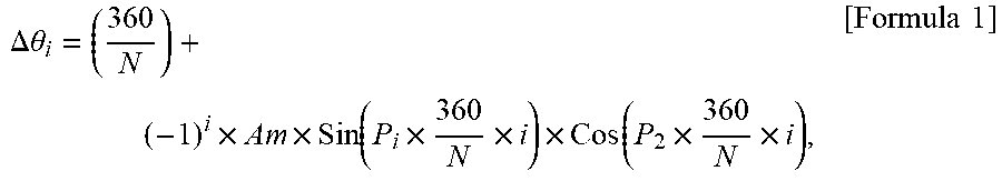
According to an aspect of the present disclosure, provided is a regenerative blower including an impeller including a plurality of blades arranged in a circumferential direction to be spaced part from each other. The plurality of blades are arranged such that angles therebetween are incremental angles .DELTA..THETA.i satisfying the formula:
.DELTA..times..times..theta..times..times..function..times..times..times.- .function..times..times. ##EQU00001##
Here, the N is a total number of the blades, where the N is a natural number greater than 2.
The Am is a distribution size of distances between the blades (equal angles), where 0.degree.<Am<360.degree./N.
The i is a sequence of the blades, where the i=1, 2, 3, 4, . . . , and N.
The P1 and the P2 are factors having an effect on a period, where 0.ltoreq.P1.ltoreq.N, and 0.ltoreq.P2.ltoreq.N, the P1 and the P2 being real numbers.
In addition, the Am, the P1, and the P2 may satisfy both relationships 27.ltoreq..eta..ltoreq.32 and 77 dB(A).ltoreq.SPL.ltoreq.83.7 dB(A).
In this case, .eta.=(P.sub.out-P.sub.in)Q/.sigma..omega., and SPL=10 log.sub.10(P/P.sub.ref).sup.2.
Here, the .eta. is efficiency, the SPL is a sound pressure level (SPL), the (P.sub.out-P.sub.in) is a total pressure, the Q is a volumetric flow, the .sigma. is a torque, the .omega. is an angular velocity, the P is a sound pressure, and the P.sub.ref is a reference pressure (2.times.10.sup.-5 Pa).
In addition, the Am may range from 1.degree. to 8.23.degree..
Furthermore, the P1 may range from 1 to 38, and the P2 ranges from 0 to 39.
According to another aspect of the present disclosure, provided is a design optimization method for the above-described regenerative blower. The design optimization method may include: a design variable and objective function selection step; a design area setting step of determining upper and lower limits of design variables; and a step of obtaining optimal solutions for objective functions in a design area.
The design optimization method may further include a step of comparing whether or not the optimal solutions, obtained in the step of obtaining the optimal solutions for the objective functions in the design area, are proper.
In the design variable and objective function selection step, the design variables may include the Am, indicating the distribution size of the distances between the blades, and the P1 and the P2, indicating the factors having an effect on the period, and the objective functions may include the .eta., indicating the efficiency, and the SPL, indicating the sound pressure level.
In addition, in the design area setting step of determining the upper and lower limits of the design variables, the Am may range from 1 to 8.23, the P1 may range from 1 to 38, and the P2 may range from 0 to 39.
Furthermore, the step of obtaining the optimal solutions for the objective functions in the design area may include: determining a plurality of test points by Latin hypercube sampling in the design area; and obtaining the objective functions at the plurality of test points by aerodynamic performance test and noise test.
In addition, the step of obtaining the optimal solutions for the objective functions in the design area may include obtaining response surfaces, on which the optimal solutions are to be calculated, using a response surface method.
Furthermore, when the response surface method is used, a response surface analysis (RSA) model of the objective functions may have function types: the .eta. is -18.8659-17.9578Am-10.5773P1-21.7493P2+7.3846AmP1+17.3858AmP2-0.789P1P2+6- .2258Am.sup.2+11.0769P1.sup.2+16.1141P2.sup.2, and the SPL is 84.2304+4.2557Am-11.8326P1-6.4429P2+8.2626AmP1+4.8169AmP2+5.9802P1P2-4.29- 59Am.sup.2+4.7855P1.sup.2+1.2078P2.sup.2.
In addition, after the step of obtaining the response surfaces, on which the optimal solutions are to be calculated, using the response surface method, the optimal solutions able to maximize the objective functions, based on the response surfaces of the objective functions obtained by the response surface method, may be obtained using a multi-objective evolutionary algorithm.
Furthermore, after the optimal solutions able to maximize the objective functions are obtained, more improved values of the optimal solutions may be obtained by localized search for the objective functions, using sequential quadratic programming (SQP), which is a gradient-based search algorithm.
In addition, the step of comparing whether or not the optimal solutions are proper may include analysis of variance (ANOVA) and regression analysis on the response surfaces of the objective functions obtained by the response surface method.
Advantageous Effects
The regenerative blower and the design optimization method for the same according to embodiments of the present disclosure are designed by multi-objective optimization, thereby allowing efficiency and noise to be selectively adjusted.
DESCRIPTION OF DRAWINGS
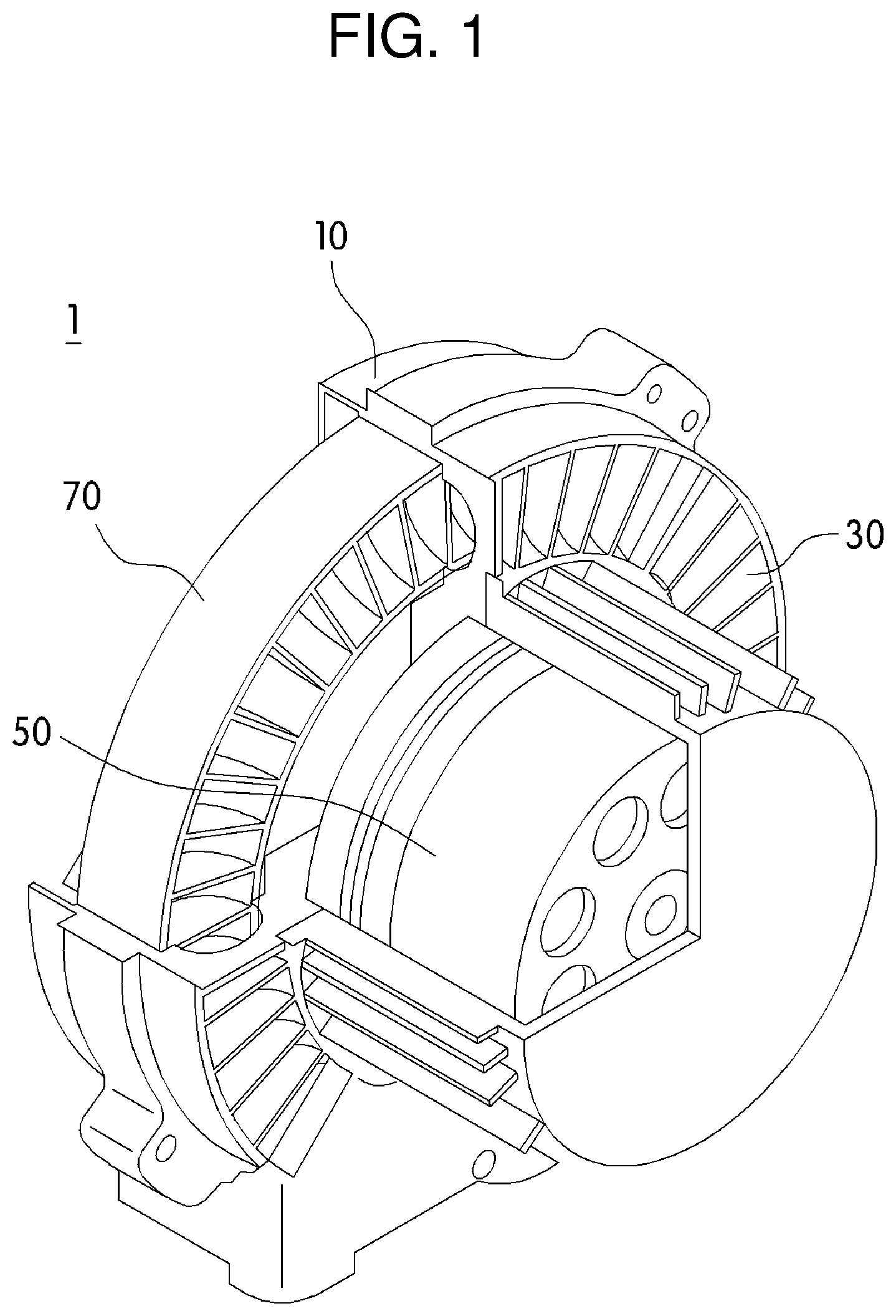
FIG. 1 is a schematic view illustrating a regenerative blower according to an embodiment of the present disclosure;
FIG. 2 is a plan view illustrating an impeller of the regenerative blower according to the embodiment of the present disclosure;
FIG. 3 is a perspective view illustrating a modification of the impeller of the regenerative blower according to the embodiment of the present disclosure;
FIG. 4 is a cross-sectional view illustrating a cross-section of FIG. 3;
FIG. 5 is a flowchart illustrating a design optimization method according to an embodiment of the present disclosure;
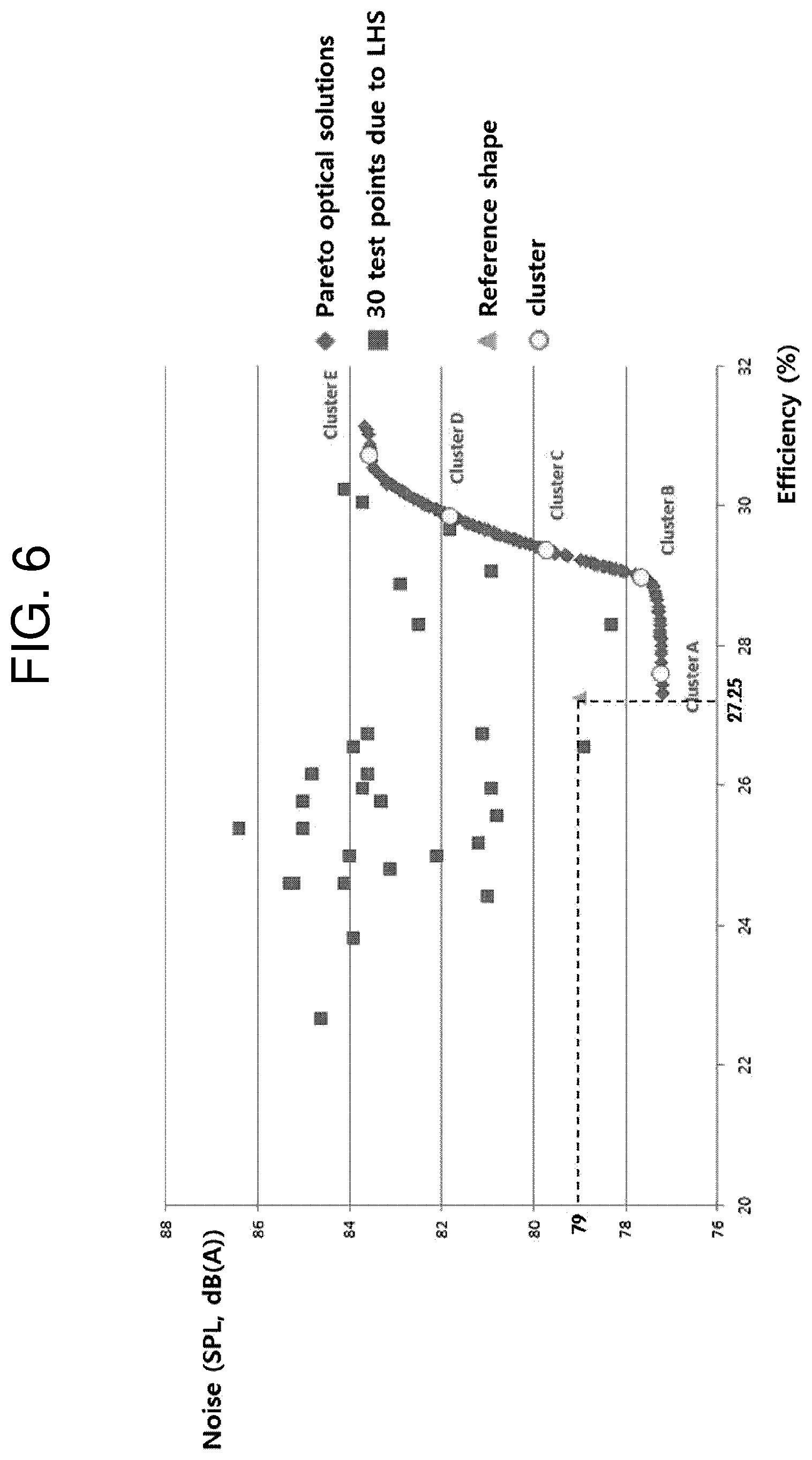
FIG. 6 is a graph illustrating the efficiencies of objective functions and sound pressure levels in the design optimization method for the regenerative blower according to the embodiment of the present disclosure; and
FIG. 7 is a graph illustrating correlations of design variables in the design optimization method for the regenerative blower according to the embodiment of the present disclosure.
MODE FOR INVENTION
Hereinafter, reference will be made to the present disclosure in detail, embodiments of which are illustrated in the accompanying drawings and described below, so that a person having ordinary skill in the art to which the present disclosure relates could easily put the present disclosure into practice. It should be understood that the present disclosure is not limited to the following embodiments but various changes in forms may be made. Throughout the drawings, the same reference numerals and symbols will be used to designate the same or like components, and specific portions will be omitted for the sake of brevity.
Hereinafter, a regenerative blower and a design optimization method for the same according to an embodiment of the present disclosure will be described in more detail with reference to the accompanying drawings.
FIG. 1 is a schematic view illustrating a regenerative blower according to an embodiment of the present disclosure, and FIG. 2 is a plan view illustrating an impeller of the regenerative blower according to the embodiment of the present disclosure.
Referring to FIGS. 1 and 2, a regenerative blower 1 according to the embodiment of the present disclosure includes an impeller 70, a first casing 10, a second casing 30, and a motor 50.
Referring to FIG. 1, in the regenerative blower 1 according to the embodiment of the present disclosure, the impeller 70 is rotatably disposed within a pair of casings, i.e. the first casing 10 and the second casing 30, which are divided to the right and left. Here, the impeller 70 is disposed on a rotary shaft (not shown) of the motor 50 to be rotated by the motor.
FIG. 3 is a perspective view illustrating a modification of the impeller of the regenerative blower according to the embodiment of the present disclosure, and FIG. 4 is a cross-sectional view illustrating a cross-section of FIG. 3.
Hereinafter, the impeller of the regenerative blower according to the embodiment of the present disclosure will be described.
Each of the impeller 70 of the regenerative blower 1 according to the embodiment of the present disclosure includes a disk 71 and a plurality of blades 73.
Referring to FIGS. 2 to 4, the disk 71 has a shaft fixing portion 71a provided on the central portion to be fixedly connected to the rotary shaft (not shown) of the regenerative blower 1. The plurality of blades may be arranged in the circumferential direction to be spaced apart from each other, on one side of the impeller as illustrated in FIG. 2 or on both sides of the impeller as illustrated in FIGS. 3 and 4.
Hereinafter, the regenerative blower 1 according to the embodiment of the present disclosure having a plurality of blades on one side of the disk will be described. However, the present disclosure is not limited thereto, and as illustrated in FIGS. 3 and 4, a plurality of blades may be disposed on both sides of the disk such that the blades are spaced apart from each other.
The shaft fixing portion 71a is fixedly connected to the rotary shaft of the regenerative blower 1, i.e. the rotary shaft of the motor, such that the disk 71 rotates along with the rotary shaft.
Flow recesses 75 are provided between the plurality of blades, with the cross-section thereof being semicircular or semi-elliptical. However, the present disclosure is not limited thereto. Since the flow recesses 75 are formed between the plurality of blades, the plurality of flow recesses 75 are spaced apart from each other.
The plurality of blades 73 are arranged at unequal pitches instead of being arranged at equal pitches such that the angles .THETA.i between the blades are unequal.
In the regenerative blower according to the embodiment of the present disclosure, the blades can be arranged at unequal pitches, due to the angles between the blades being set to incremental angles .DELTA..THETA.i according to Formula 1.
.DELTA..times..times..theta..times..times..function..times..times..times.- .function..times..times..times..times. ##EQU00002##
where N is the total number of the blades (N is a natural number greater than 2),
Am is a distribution size of the distances between the blades (equal angles) (0.degree.<Am<360.degree./N),
i is a sequence of the blades (i=1, 2, 3, 4, . . . , and N), and
P1 and P2 are factors having an effect on the period (0.ltoreq.P1.ltoreq.N, and 0.ltoreq.P2.ltoreq.N, where P1 and P2 are real numbers).
Here, according to a reference shape, the blades of the impeller shall be arranged at equal pitches due to the same angles between the blades, and the sum of the incremental angles .DELTA..THETA.i shall satisfy 360.degree..
Due to the incremental angles .DELTA..THETA.i, the impeller 70 can satisfy an unequal pitch condition having the same structure even in the case in which the number of the blades 73 changes. In addition, since generated functions have the shape of an oscillation divergence function due to a term (-1).sup.i, the average of the incremental angles can be set to be similar to an overall average.
In the regenerative blower 1 according to the embodiment of the present disclosure, the time intervals of the blades 73 and the blades passing through the adjacent partitions are scattered. This consequently reduces high-frequency sound and disperses sound pressure throughout a plurality of frequency bands, thereby reducing blade-passing frequency (BPF) in the high-frequency region.
For example, when the total number of blades is N=39, the average of the angles of the blades is 360.degree./39=9.2.degree..
To satisfy the conditions presented in the above formula, Am indicating the distribution size of the distances of the blades (equal angles), as well as the factors P1 and P2 having an effect on the period, are controlled. Since a pitch condition similar to a random pitch condition and a pitch condition having a predetermined distance can be generated by controlling the values Am, P1, and P2, it is possible to easily predict and adjust the arrangement of the blades.
FIG. 5 is a flowchart illustrating a design optimization method according to an embodiment of the present disclosure.
The design optimization method for the regenerative blower according to the embodiment of the present disclosure can adjust both the efficiency and noise of the regenerative blower by modifying the distances of the blades to unequal pitches using multi-objective optimization.
In the design optimization method for the regenerative blower according to the embodiment of the present disclosure, optimization refers to ability to adjust efficiency and noise as required, compared to the reference shape of the impeller having equal pitches. That is, it is possible to improve both efficiency and noise, improve efficiency alone, or improve noise alone. In this regard, according to the embodiment of the present disclosure, the design optimization method for the regenerative blower includes design variable and objective function selection step S10, design area setting step S20 of determining upper and lower limits of design variables, step S30 of obtaining optimal solutions for objective functions in a design area, and optimal solution comparison step S40.
The design optimization method for the regenerative blower according to the embodiment of the present disclosure selects design variables for the regenerative blower 10 and optimizes objective functions within the design area.
First, in the design variable and objective function selection step S10, the objective functions are obtained by aerodynamic and noise performance test, and design variables for determining the unequal pitches of the blades are set in order to optimize the obtained objective functions.
According to the present embodiment, in the design variables Am, P1, and P2, Am is the distribution size of the distances of the blades (equal angles) (0.degree.<Am<360/N.degree.), while P1 and P2 are factors having an effect on the period (0<P1<N, and 0.ltoreq.P2.ltoreq.N, where P1 and P2 are real numbers).
The geometric parameters Am, P1, and P2 related to the unequal pitches of the blades 73 can be used as design values to optimize both efficiency .eta. and a sound pressure level SPL in the regenerative blower 1. In this case, it is important to determine a formed movable design space by establishing the ranges of the design variables.
In addition, since the regenerative blower 1 according to the embodiment of the present disclosure is intended to optimize both efficiency and noise by optimizing the shape of the unequal pitches of the blades, the objective functions can be set using the efficiency .eta. and the sound pressure level SPL.
Afterwards, in the design area setting step S20 of determining upper and lower limits of design variables, the ranges of the design variables are defined for the realization of design optimization, thereby setting a proper design range.
The upper and lower limits of the design variables to be changed during the process of design optimization can be determined by the minimum thickness of a drill or a blade used for the fabrication of the impeller. When the design variables set by the inventors of the present disclosure are applied to Formula 1, the upper and lower limits are obtained as in Table 1.
TABLE-US-00001 TABLE 1 Variables Minimum Maximum Am 1 degree 8.23 degrees P1 1 38 P2 0 39
According to the embodiment of the present disclosure, the design variable Am ranges from 1.degree. to 8.23.degree., the design variable P1 ranges from 1 to 38, and the design variable P2 ranges from 0 to 39.
Afterwards, in the test step S30, values of the object function are determined, for example, at 30 test points by performing a test in the set design area.
Here, the 30 test points can be determined by Latin hypercube sampling (LHS) available for sampling specific test points in the design area having a multidimensional distribution. The objective functions .eta. and SPL at 30 test points can be obtained by aerodynamic performance test and noise test.
In the optimal solution comparison step S40 of obtaining optimal solutions for the objective functions in the design area based on the test result, response surfaces on which optimal points will be calculated can be formed using a response surface method, namely, a type of surrogate model.
Various types of hydrodynamic performance of the regenerative blower 10 according to the embodiment of the present disclosure can be improved by multi-objective optimization of the regenerative blower 10. The object of optimization is to optimize both the efficiency .eta. and sound pressure level SPL of the regenerative blower. Here, .eta. and SPL, objective functions for the design optimization of the regenerative blower, can be defined as follows:
.eta..sigma..omega..times..times..times..times..function..times..times. ##EQU00003##
Here, .eta. is efficiency, SPL is a sound pressure level, (P.sub.out-P.sub.in) is a total pressure, Q is a volumetric flow, .sigma. is a torque, .omega. is an angular velocity, P is a sound pressure, and P.sub.ref is a reference pressure (2.times.10.sup.-5 Pa).
The response surface method is a mathematical/statistical method of modeling an actual response function into an approximate polynomial function by using results obtained from physical tests or numerical calculations.
The response surface method can reduce the number of tests by modeling responses in a space using a limited number of tests. Response surfaces defined by a secondary polynomial used herein can be expressed as follows:
.function..times..times..times..chi..times..times..chi..times..times..chi- ..times..chi..times..times. ##EQU00004##
Here, C indicates a regression coefficient, n indicates the number of design variables, and x indicates design variables.
In this case, the regression coefficient is represented by Formula 5: (C.sub.0,C.sub.1,etc)=(n+1).times.(n+2)/2 [Formula 5]
Here, the function type of an response surface analysis (RSA) model of the objective functions according to the embodiment of the present disclosure can be expressed, with respect to normalized design variables, as follows: .eta.=-1838659-19.9878Am-10.5773P1-21.7493P2+7.3846AmP1+17.3858AmP2-0.789- P1P2+6.2258Am.sup.2+11.0769P1.sup.2+16.1141P2.sup.2 [Formula 6] SPL=84.2304+4.2557Am-11.8326P1-6.4429P2+8.2626AmP1+4.8169AmP2+5.9802P1P2-- 4.2959Am.sup.2+4.7855P1.sup.2+1.2078P2.sup.2 [Formula 7]
Afterwards, .eta. and SPL satisfying Formulae 6 and 7 are obtained.
In addition, according to the embodiment of the present disclosure, in order to optimize both .eta. and SPL, a multi-objective evolutionary algorithm able to maximize the objective functions, based on the response surfaces of the objective functions obtained by the response surface method, can be used.
The multi-objective evolutionary algorithm may be implemented as real-coded NSGA-II developed by Deb. Here, the term "real coded" means that crossing and variation are performed in the actual design space to form the response of NSGA-II.
The optimal points obtained by the multi-objective evolutionary algorithm are referred to as a Pareto optimal solution, i.e. an assembly of non-dominant solutions. The Pareto optimal solution allows intended optimal solutions to be selected according to the intention of the objective to be used.
Since the multi-objective evolutionary algorithm is well-known in the art, a detailed description thereof will be omitted.
In addition, optimal points can be found by evaluating values of objective functions for test points, obtained by Latin hypercube sampling (LHS), and using sequential quadratic programming (SQP) based on the evaluated objective functions.
More improved optimal solutions for the objective functions can be obtained by localized search for objective functions from solutions predicted by initial NSGA-II, using sequential quadratic programming (SQP), i.e. a gradient-based search algorithm.
Here, SQP is a well-known method for optimizing nonlinear objective functions under nonlinear constraints, and thus a detailed description thereof will be omitted.
Consequently, Pareto optimal solutions, i.e. an assembly of non-dominant solutions, can be obtained by discarding dominant solutions from the optimal solutions improved as above ant then removing overlapping solutions. A group of units categorized among the Pareto optimal solutions will be referred to as a cluster.
FIG. 6 is a graph illustrating the efficiencies of Pareto optimal solutions (clustered optimal solutions (COSs)) and sound pressure levels, derived from the multi-objective numerical optimization method for the regenerative blower according to the embodiment of the present disclosure.
Referring to FIG. 6, Pareto optimal solutions can have an S-shaped profile due to the optimization of objective functions regarding efficiency and noise. A trade-off analysis shows the correlation between two objective functions.
Thus, in the regenerative blower 1 according to the embodiment of the present disclosure, a higher efficiency can be obtained at a higher noise level, and in contrast, a lower efficiency can be obtained at a lower noise level.
As illustrated in FIG. 6, Am, P1, and P2 can satisfy both relationships 2732 and 77 dB(A).ltoreq.SPL.ltoreq.83.7 dB(A). Am, P1, and P2 values satisfying these relationships, corresponding to the graph of the Pareto optimal solutions illustrated in FIG. 6, are represented in Table 2.
TABLE-US-00002 TABLE 2 Design Variable Objective Function Am P1 P2 Efficiency (.eta.) Noise (SPL dB(A)) X1 Y1 Z1 31.139 83.6854983 X2 Y2 Z2 31.139 83.685049 X3 Y3 Z3 31.082 83.6160881 X4 Y4 Z4 31.078 83.6160881 X5 Y5 Z5 31.078 83.614491 X6 Y6 Z6 31.031 83.6011141 X7 Y7 Z7 31.009 83.5965554 X8 Y8 Z8 30.877 83.5760955 X9 Y9 Z9 30.85 83.5727465 X10 Y10 Z10 30.818 83.5689124 X11 Y11 Z11 30.812 83.5689124 X12 Y12 Z12 30.812 83.5682137 X13 Y13 Z13 30.723 83.5586193 X14 Y14 Z14 30.708 83.5586193 X15 Y15 Z15 30.708 83.5571499 X16 Y16 Z16 30.656 83.5519518 X17 Y17 Z17 30.656 83.5519518 X18 Y18 Z18 30.656 83.5519497 X19 Y19 Z19 30.63 83.5494975 X20 Y20 Z20 30.63 83.5494974 X21 Y21 Z21 30.63 83.549457 X22 Y22 Z22 30.551 83.500479 X23 Y23 Z23 30.542 83.4892842 X24 Y24 Z24 30.513 83.4502087 X25 Y25 Z25 30.508 83.4434578 X26 Y26 Z26 30.489 83.4152326 X27 Y27 Z27 30.484 83.4152326 X28 Y28 Z28 30.484 83.4082556 X29 Y29 Z29 30.422 83.3067451 X30 Y30 Z30 30.409 83.3067451 X31 Y31 Z31 30.409 83.2855466 X32 Y32 Z32 30.384 83.2389053 X33 Y33 Z33 30.38 83.2324381 X34 Y34 Z34 30.357 83.1882198 X35 Y35 Z35 30.311 83.1882198 X36 Y36 Z36 30.311 83.0936043 X37 Y37 Z37 30.303 83.0771505 X38 Y38 Z38 30.301 83.0771505 X39 Y39 Z39 30.301 83.0730728 X40 Y40 Z40 30.277 83.0206437 X41 Y41 Z41 30.271 83.0065799 X42 Y42 Z42 30.267 82.999347 X43 Y43 Z43 30.236 82.9278265 X44 Y44 Z44 30.231 82.9161717 X45 Y45 Z45 30.211 82.9161716 X46 Y46 Z46 30.211 82.8669657 X47 Y47 Z47 30.193 82.8231613 X48 Y48 Z48 30.188 82.8231613 X49 Y49 Z49 30.188 82.8103652 X50 Y50 Z50 30.182 82.7949826 X51 Y51 Z51 30.172 82.7949826 X52 Y52 Z52 30.172 82.7704206 X53 Y53 Z53 30.154 82.7221752 X54 Y54 Z54 30.145 82.6989278 X55 Y55 Z55 30.109 82.6004421 X56 Y56 Z56 30.109 82.6004421 X57 Y57 Z57 30.109 82.5998025 X58 Y58 Z58 30.081 82.5215336 X59 Y59 Z59 30.08 82.5215336 X60 Y60 Z60 30.08 82.5204012 X61 Y61 Z61 30.047 82.4223153 X62 Y62 Z62 30.037 82.4223152 X63 Y63 Z63 30.037 82.3926777 X64 Y64 Z64 30.029 82.3707481 X65 Y65 Z65 30.014 82.3707481 X66 Y66 Z66 30.014 82.3225576 X67 Y67 Z67 30.007 82.3027607 X68 Y68 Z68 30.005 82.3027607 X69 Y69 Z69 30.005 82.2954184 X70 Y70 Z70 29.997 82.2712994 X71 Y71 Z71 29.993 82.2712994 X72 Y72 Z72 29.993 82.258459 X73 Y73 Z73 29.96 82.1528175 X74 Y74 Z74 29.958 82.1528175 X75 Y75 Z75 29.958 82.1480858 X76 Y76 Z76 29.952 82.1266986 X77 Y77 Z77 29.942 82.1266986 X78 Y78 Z78 29.942 82.0935959 X79 Y79 Z79 29.923 82.0300972 X80 Y80 Z80 29.915 82.0057523 X81 Y81 Z81 29.915 82.0051106 X82 Y82 Z82 29.901 82.0051106 X83 Y83 Z83 29.901 81.9565135 X84 Y84 Z84 29.89 81.9182115 X85 Y85 Z85 29.885 81.9182115 X86 Y86 Z86 29.885 81.9001068 X87 Y87 Z87 29.858 81.8058797 X88 Y88 Z88 29.855 81.8058797 X89 Y89 Z89 29.855 81.7946998 X90 Y90 Z90 29.844 81.757571 X91 Y91 Z91 29.834 81.757571 X92 Y92 Z92 29.834 81.720742 X93 Y93 Z93 29.828 81.698315 X94 Y94 Z94 29.823 81.698315 X95 Y95 Z95 29.823 81.6791706 X96 Y96 Z96 29.812 81.6394203 X97 Y97 Z97 29.812 81.6394202 X98 Y98 Z98 29.812 81.6387048 X99 Y99 Z99 29.772 81.4904461 X100 Y100 Z100 29.77 81.4815631 X101 Y101 Z101 29.752 81.4119061 X10² Y102 Z102 29.751 81.4119061 X10³ Y103 Z103 29.751 81.4090656 X10⁴ Y104 Z104 29.732 81.3337476 X10⁵ Y105 Z105 29.73 81.3337476 X10⁶ Y106 Z106 29.73 81.3273069 X10⁷ Y107 Z107 29.718 81.2791408 X10⁸ Y108 Z108 29.717 81.276571 X10⁹ Y109 Z109 29.695 81.1898352 X110 Y110 Z110 29.692 81.1898352 X111 Y111 Z111 29.692 81.1774201 X112 Y112 Z112 29.668 81.0786783 X113 Y113 Z113 29.66 81.0786783 X114 Y114 Z114 29.66 81.046998 X115 Y115 Z115 29.647 80.9929066 X116 Y116 Z116 29.646 80.9929064 X117 Y117 Z117 29.646 80.9891169 X118 Y118 Z118 29.621 80.8821232 X119 Y119 Z119 29.615 80.8821231 X120 Y120 Z120 29.615 80.8578277 X121 Y121 Z121 29.613 80.847616 X122 Y122 Z122 29.602 80.847616 X123 Y123 Z123 29.602 80.7998398 X124 Y124 Z124 29.587 80.7337917 X125 Y125 Z125 29.584 80.7240269 X126 Y126 Z126 29.561 80.6193814 X127 Y127 Z127 29.557 80.6034128 X128 Y128 Z128 29.545 80.5483062 X129 Y129 Z129 29.541 80.5483062 X130 Y130 Z130 29.541 80.532873 X131 Y131 Z131 29.525 80.4615232 X132 Y132 Z132 29.523 80.4615232 X133 Y133 Z133 29.523 80.4527967 X134 Y134 Z134 29.515 80.4137528 X135 Y135 Z135 29.514 80.4137528 X136 Y136 Z136 29.514 80.4088387 X137 Y137 Z137 29.493 80.316339 X138 Y138 Z138 29.493 80.316339 X139 Y139 Z139 29.493 80.312363 X140 Y140 Z140 29.484 80.2720951 X141 Y141 Z141 29.484 80.2720951 X142 Y142 Z142 29.484 80.270587 X143 Y143 Z143 29.465 80.183932 X144 Y144 Z144 29.464 80.183932 X145 Y145 Z145 29.464 80.1814693 X146 Y146 Z146 29.46 80.1602507 X147 Y147 Z147 29.459 80.1602507 X148 Y148 Z148 29.459 80.1572512 X149 Y149 Z149 29.441 80.0724229 X150 Y150 Z150 29.441 80.0724229 X151 Y151 Z151 29.441 80.0681446 X152 Y152 Z152 29.42 79.969017 X153 Y153 Z153 29.416 79.9522104 X154 Y154 Z154 29.403 79.8887543 X155 Y155 Z155 29.398 79.8887543 X156 Y156 Z156 29.398 79.8619606 X157 Y157 Z157 29.385 79.7984225 X158 Y158 Z158 29.37 79.7243407 X159 Y159 Z159 29.367 79.7114422 X160 Y160 Z160 29.356 79.6572799 X161 Y161 Z161 29.351 79.6305195 X162 Y162 Z162 29.349 79.6305195 X163 Y163 Z163 29.349 79.6196693 X164 Y164 Z164 29.333 79.5376174 X165 Y165 Z165 29.327 79.5376174 X166 Y166 Z166 29.327 79.5109327 X167 Y167 Z167 29.292 79.3289859 X168 Y168 Z168 29.29 79.3221988 X169 Y169 Z169 29.278 79.2594319 X170 Y170 Z170 29.277 79.2594319 X171 Y171 Z171 29.277 79.2533121 X172 Y172 Z172 29.227 78.9867782 X173 Y173 Z173 29.227 78.986778 X174 Y174 Z174 29.227 78.9865995 X175 Y175 Z175 29.204 78.8663784 X176 Y176 Z176 29.203 78.8612056 X177 Y177 Z177 29.183 78.7519735 X178 Y178 Z178 29.182 78.7458862 X179 Y179 Z179 29.175 78.7088752 X180 Y180 Z180 29.167 78.6610085 X181 Y181 Z181 29.167 78.6606544 X182 Y182 Z182 29.157 78.6606544 X183 Y183 Z183 29.157 78.6053284 X184 Y184 Z184 29.136 78.493905 X185 Y185 Z185 29.134 78.493905 X186 Y186 Z186 29.134 78.4773519 X187 Y187 Z187 29.131 78.4626734 X188 Y188 Z188 29.13 78.4561662 X189 Y189 Z189 29.112 78.3558916 X190 Y190 Z190 29.111 78.3518051 X191 Y191 Z191 29.108 78.3360681 X192 Y192 Z192 29.1 78.2894346 X193 Y193 Z193 29.09 78.230936 X194 Y194 Z194 29.088 78.2177256 X195 Y195 Z195 29.07 78.1170001 X196 Y196 Z196 29.069 78.1169998 X197 Y197 Z197 29.069 78.1133521 X198 Y198 Z198 29.059 78.0505559 X199 Y199 Z199 29.049 77.9971649 X200 Y200 Z200 29.015 77.7966686 X201 Y201 Z201 29.014 77.7922567 X202 Y202 Z202 28.998 77.6952289 X203 Y203 Z203 28.997 77.6952288 X204 Y204 Z204 28.997 77.6892224 X205 Y205 Z205 28.989 77.6398967 X206 Y206 Z206 28.988 77.639896 X207 Y207 Z207 28.988 77.6371251 X208 Y208 Z208 28.964 77.550832 X209 Y209 Z209 28.94 77.5029929 X210 Y210 Z210 28.915 77.4679489 X211 Y211 Z211 28.907 77.459104 X212 Y212 Z212 28.849 77.4048382 X213 Y213 Z213 28.845 77.4016137 X214 Y214 Z214 28.842 77.3993036 X215 Y215 Z215 28.833 77.3930941 X216 Y216 Z216 28.787 77.3647676 X217 Y217 Z217 28.742 77.342861 X218 Y218 Z218 28.711 77.3299637 X219 Y219 Z219 28.708 77.3286827 X220 Y220 Z220 28.656 77.3109567 X221 Y221 Z221 28.648 77.3109567 X222 Y222 Z222 28.648 77.3085502 X223 Y223 Z223 28.554 77.2855233 X224 Y224 Z224 28.553 77.2852977 X225 Y225 Z225 28.495 77.2750232 X226 Y226 Z226 28.483 77.2750232 X227 Y227 Z227 28.483 77.2731263 X228 Y228 Z228 28.473 77.2716347 X229 Y229 Z229 28.388 77.2615579 X230 Y230 Z230 28.344 77.2575197 X231 Y231 Z231 28.298 77.2575197 X232 Y232 Z232 28.298 77.2539949 X233 Y233 Z233 28.216 77.2485304 X234 Y234 Z234 28.183 77.2485304 X235 Y235 Z235 28.183 77.246576 X236 Y236 Z236 28.146 77.2444507 X237 Y237 Z237 28.131 77.2444507 X238 Y238 Z238 28.131 77.2436537 X239 Y239 Z239 28.102 77.2420587 X240 Y240 Z240 28.086 77.2420587 X241 Y241 Z241 28.086 77.2412236 X242 Y242 Z242 28.006 77.237066 X243 Y243 Z243 28.006 77.237066 X244 Y244 Z244 28.006 77.2370655 X245 Y245 Z245 27.921 77.2328987
X246 Y246 Z246 27.891 77.2328987 X247 Y247 Z247 27.891 77.2314741 X248 Y248 Z248 27.755 77.2251261 X249 Y249 Z249 27.755 77.2251261 X250 Y250 Z250 27.755 77.2251185 X251 Y251 Z251 27.67 77.2212663 X252 Y252 Z252 27.641 77.2212663 X253 Y253 Z253 27.641 77.2199893 X254 Y254 Z254 27.598 77.2180905 X255 Y255 Z255 27.587 77.2180905 X256 Y256 Z256 27.587 77.2175869 X257 Y257 Z257 27.434 77.2109748 X258 Y258 Z258 27.433 77.2109748 X259 Y259 Z259 27.433 77.2109123 X260 Y260 Z260 27.327 77.2064116 X261 Y261 Z261 27.327 77.2064116 X262 Y262 Z262 27.327 77.2064116 X263 Y263 Z263 27.31 77.2060668 X264 Y264 Z264 27.31 77.2060668
Here, Table 3 represents optimal design variations Am, P1, and P2 for clusters A, B, C, D, and E, i.e. groups in which both efficiency and nose are optimized. In this case, the reference shape has an efficiency .eta. of 27.25 and an SPL of 79 dB(A).
TABLE-US-00003 TABLE 3 Design Variables Design Am P1 P2 Reference Shape 0.000 0.000 0.000 Cluster A 1 23.96992 37.72269 Cluster B 1 20.31293 26.94253 Cluster C 1.975457 18.18757 23.56059 Cluster D 3.27427 15.95297 18.60822 Cluster E 6.793103 12.29705 1.858063
Referring to Table 3, a design variable Am increases while design variables P1 and P2 decrease from an optimal point A to an optimal point E. Here, the decreasing gradient of P2 is greater than the decreasing gradient of P1. It can be appreciated from the trade-off analysis that, among the three design variables, Am has a proportional relationship, while each of P1 and P2 has an inverse proportional relationship.
Here, referring to the reference shape, Am, P1, and P2 are 0 (points designated with triangles in FIG. 6), since the inter-blade pitches thereof are equal. Referring to Cluster A, Am is 1, P1 is 23.96992, and P2 is 37.72269. Referring to Cluster B, Am is 1, P1 is 20.31293, and P2 is 26.94253. Referring to Cluster C, Am is 1.975457, P1 is 18.18757, and P2 is 23.56059. Referring to Cluster D, Am is 3.27427, P1 is 15.95297, and P2 is 18.60822. Referring to Cluster E, Am is 6.793103, P1 is 12.29705, and P2 is 1.858063.
Referring to FIGS. 6 and 7, the three optimal design variables can significantly change compared to the values of the reference shape, and the efficiency and noise are significantly improved at all of the optimal points. It is therefore possible to select a value of efficiency and a sound pressure level.
Therefore, it can be understood that the noise and efficiency increase from the optimal point A to optimal point E, the optimal point (COSs) A indicates the lowest noise level and efficiency, and the optimal point (COSs) E indicates the highest noise level and efficiency.
In the optimal solution comparison step S40 according to the embodiment of the present disclosure, it is examined whether or not the obtained optimal points are reliable by performing analysis of variance (ANOVA) and regression analysis on the response surfaces of the objective functions formed by the response surface method.
Table 4 represents the results of analysis of variance and regression analysis.
TABLE-US-00004 TABLE 4 Objective Root-Mean- Cross Verification Function R.sup.2 R.sup.2.sub.adj Square Error Error .eta. 0.977 0.948 4.73 .times. 10.sup.-1 7.50 .times. 10.sup.-1 SPL 0.898 0.933 5.49 .times. 10.sup.-1 9.40 .times. 10.sup.-1
Here, an R.sup.2 value may indicate a correlation coefficient in least square surface fitting, while a R.sup.2.sub.adj value may indicate an adjusted correlation coefficient in least square surface fitting. In this case, Ginuta explained that the R.sup.2.sub.adj value ranges from 0.9 to 1 when a response model based on the response surface method is accurately predicted.
The root-mean-square error indicates a root-mean-square value of errors occurring in experiment or observation, while the cross verification error is a method of calculating predicted errors.
The R.sup.2.sub.adj values of the efficiency and noise, i.e. the objective functions calculated in the optimal solution comparison step S40 according to the embodiment of the present disclosure, are 0.948 and 0.933, respectively. It can therefore be judged that the response surface is reliable.
In the regenerative blower and the design optimization method for the same according to embodiments of the present disclosure, the blades are arranged at unequal pitches by multi-objective optimization, thereby allowing efficiency and noise to be selectively adjusted.
Although the specific embodiments of the present disclosure have been described for illustrative purposes, the scope of the present disclosure is limited by no means to the foregoing embodiments of the present disclosure. A person skilled in the art could easily make many other embodiments by adding, modifying, omitting, supplementing elements without departing from the principle of the present disclosure.
INDUSTRIAL APPLICABILITY
The regenerative blower and the design optimization method for the same according to embodiments of the present disclosure are designed by multi-objective optimization, thereby allowing efficiency and noise to be selectively adjusted.
* * * * *
References
D00000
D00001
D00002
D00003
D00004
D00005
D00006
D00007
M00001
M00002
M00003
M00004
M00005

XML
uspto.report is an independent third-party trademark research tool that is not affiliated, endorsed, or sponsored by the United States Patent and Trademark Office (USPTO) or any other governmental organization. The information provided by uspto.report is based on publicly available data at the time of writing and is intended for informational purposes only.
While we strive to provide accurate and up-to-date information, we do not guarantee the accuracy, completeness, reliability, or suitability of the information displayed on this site. The use of this site is at your own risk. Any reliance you place on such information is therefore strictly at your own risk.
All official trademark data, including owner information, should be verified by visiting the official USPTO website at www.uspto.gov. This site is not intended to replace professional legal advice and should not be used as a substitute for consulting with a legal professional who is knowledgeable about trademark law.