Internal combustion engine
Dalmas, II , et al.
U.S. patent number 10,590,813 [Application Number 15/938,130] was granted by the patent office on 2020-03-17 for internal combustion engine. This patent grant is currently assigned to Quest Engines, LLC. The grantee listed for this patent is Quest Engines, LLC. Invention is credited to Roy A. Blom, Elario Dino Dalmas, II.


View All Diagrams
| United States Patent | 10,590,813 |
| Dalmas, II , et al. | March 17, 2020 |
Internal combustion engine
Abstract
Internal combustion engines having multi-stage telescoping poppet valves in lieu of conventional poppet valves are disclosed. The engines may have pistons with a skirt with a field of pockets that provide a ringless, non-lubricated, seal equivalent. The piston heads may include one or more depressions and may be domed to facilitate the movement of air/charge in the cylinder. The engines may also have non-circular, preferably rectangular, cross-section pistons and cylinders. The engines also may include a split crankshaft. The engines may use the pumping motion of the engine piston to supercharge the cylinder with air/charge. The engines also may operate in an inverted orientation in which the piston is closer to the local gravitationally dominant terrestrial body's center of gravity at top dead center position than at bottom dead center position.
| Inventors: | Dalmas, II; Elario Dino (Macungie, PA), Blom; Roy A. (Coopersburg, PA) | ||||||||||
|---|---|---|---|---|---|---|---|---|---|---|---|
| Applicant: |
|
||||||||||
| Assignee: | Quest Engines, LLC
(N/A) |
||||||||||
| Family ID: | 63672578 | ||||||||||
| Appl. No.: | 15/938,130 | ||||||||||
| Filed: | March 28, 2018 |
Prior Publication Data
| Document Identifier | Publication Date | |
|---|---|---|
| US 20180283235 A1 | Oct 4, 2018 | |
Related U.S. Patent Documents
| Application Number | Filing Date | Patent Number | Issue Date | ||
|---|---|---|---|---|---|
| 15936713 | Mar 27, 2018 | ||||
| 15937293 | Mar 27, 2018 | ||||
| 15934742 | Mar 23, 2018 | ||||
| 15934625 | Mar 23, 2018 | ||||
| 15903636 | Feb 23, 2018 | ||||
| 62501295 | May 4, 2017 | ||||
| 62491629 | Apr 28, 2017 | ||||
| 62479013 | Mar 30, 2017 | ||||
| Current U.S. Class: | 1/1 |
| Current CPC Class: | F01M 11/0408 (20130101); F01L 1/08 (20130101); F02F 1/183 (20130101); F02B 33/12 (20130101); F01M 11/0004 (20130101); F01L 1/462 (20130101); F01M 9/06 (20130101); F01L 3/085 (20130101); F01L 1/28 (20130101); F01L 1/185 (20130101); F02F 3/027 (20130101); F01L 13/0015 (20130101); F01L 13/0036 (20130101); F01M 3/00 (20130101); F02F 3/022 (20130101); F02F 3/28 (20130101); F02F 1/242 (20130101); F01L 2303/00 (20200501); F01L 2001/0537 (20130101); F02B 33/04 (20130101); F01L 1/2405 (20130101); F01L 2305/00 (20200501); F01M 13/00 (20130101) |
| Current International Class: | F01L 3/08 (20060101); F01L 1/28 (20060101); F01L 13/00 (20060101); F01L 1/18 (20060101); F02F 3/02 (20060101); F01M 11/04 (20060101); F01M 3/00 (20060101); F02F 1/18 (20060101); F01M 9/06 (20060101); F01M 11/00 (20060101); F01L 1/08 (20060101); F02B 33/12 (20060101); F01L 1/46 (20060101); F01L 1/24 (20060101); F01L 1/053 (20060101); F02F 1/24 (20060101); F02B 33/04 (20060101); F01M 13/00 (20060101); F02F 3/28 (20060101) |
References Cited [Referenced By]
U.S. Patent Documents
| 1016561 | February 1912 | Grabler |
| 1046359 | December 1912 | Winton |
| 1329559 | February 1920 | Tesla |
| 1418838 | June 1922 | Setz |
| 1511338 | October 1924 | Cyril |
| 1527166 | February 1925 | Maurice |
| 1639308 | August 1927 | Orr |
| 1869178 | July 1932 | Thuras |
| 1967682 | July 1934 | Ochtman, Jr. |
| 1969704 | August 1934 | D'Alton |
| 2025297 | December 1935 | Meyers |
| 2224475 | December 1940 | Evans |
| 2252914 | August 1941 | Balton |
| 2283567 | May 1942 | Barton |
| 2442917 | June 1948 | Butterfield |
| 2451271 | October 1948 | Balster |
| 2468976 | May 1949 | Herreshoff |
| 2471509 | May 1949 | Anderson |
| 2878990 | March 1950 | Zurcher |
| 2644433 | July 1953 | Anderson |
| 2761516 | September 1956 | Vassilkovsky |
| 2766839 | October 1956 | Baruch |
| 2898894 | August 1959 | Holt |
| 2915050 | December 1959 | Allred |
| 2956738 | October 1960 | Rosenschold |
| 2977943 | April 1961 | Lieberherr |
| 2979046 | April 1961 | Buchi |
| 3033184 | May 1962 | Jackson |
| 3035879 | May 1962 | Jost |
| 3113561 | December 1963 | Heintz |
| 3143282 | August 1964 | McCrory |
| 3154059 | October 1964 | Witzky |
| 3171425 | March 1965 | Berlyn |
| 3275057 | September 1966 | Trevor |
| 3399008 | August 1968 | Farrell |
| 3409410 | November 1968 | Spence |
| 3491654 | January 1970 | Zurcher |
| 3534771 | October 1970 | Everdam |
| 3621821 | November 1971 | Jarnuszkiewicz |
| 3749318 | July 1973 | Cottell |
| 3881459 | May 1975 | Gaetcke |
| 3892070 | July 1975 | Bose |
| 3911753 | October 1975 | Daub |
| 3973532 | August 1976 | Litz |
| 4043224 | August 1977 | Quick |
| 4046028 | September 1977 | Vachris |
| 4077429 | March 1978 | Kimball |
| 4127332 | November 1978 | Thiruvengadam |
| 4128388 | December 1978 | Freze |
| 4164988 | August 1979 | Virva |
| 4182282 | January 1980 | Pollet |
| 4185597 | January 1980 | Cinquegrani |
| 4271803 | June 1981 | Nakanishi |
| 4300499 | November 1981 | Nakanishi |
| 4312305 | January 1982 | Noguchi |
| 4324214 | April 1982 | Garcea |
| 4331118 | May 1982 | Cullinan |
| 4332229 | June 1982 | Schuit |
| 4343605 | August 1982 | Browning |
| 4357916 | November 1982 | Noguchi |
| 4383508 | May 1983 | Irimajiri |
| 4467752 | August 1984 | Yunick |
| 4480597 | November 1984 | Noguchi |
| 4488866 | December 1984 | Schirmer |
| 4541377 | September 1985 | Amos |
| 4554893 | November 1985 | Vecellio |
| 4570589 | February 1986 | Fletcher |
| 4576126 | March 1986 | Ancheta |
| 4592318 | June 1986 | Pouring |
| 4597342 | July 1986 | Green |
| 4598687 | July 1986 | Hayashi |
| 4669431 | June 1987 | Simay |
| 4715791 | December 1987 | Berlin |
| 4724800 | February 1988 | Wood |
| 4756674 | July 1988 | Miller |
| 4788942 | December 1988 | Pouring |
| 4836154 | June 1989 | Bergeron |
| 4874310 | October 1989 | Seemann |
| 4879974 | November 1989 | Alvers |
| 4919611 | April 1990 | Flament |
| 4920937 | May 1990 | Sasaki |
| 4936269 | June 1990 | Beaty |
| 4969425 | November 1990 | Slee |
| 4990074 | February 1991 | Nakagawa |
| 4995349 | February 1991 | Tuckey |
| 5004066 | April 1991 | Furukawa |
| 5007392 | April 1991 | Niizato |
| 5020504 | June 1991 | Morikawa |
| 5083539 | January 1992 | Cornelio |
| 5154141 | October 1992 | McWhorter |
| 5168843 | December 1992 | Franks |
| 5213074 | May 1993 | Imagawa |
| 5222879 | June 1993 | Kapadia |
| 5251817 | October 1993 | Ursic |
| 5343618 | September 1994 | Arnold |
| 5357919 | October 1994 | Ma |
| 5390634 | February 1995 | Walters |
| 5397180 | March 1995 | Miller |
| 5398645 | March 1995 | Haman |
| 5454712 | October 1995 | Yap |
| 5464331 | November 1995 | Sawyer |
| 5479894 | January 1996 | Noltemeyer |
| 5694891 | December 1997 | Liebich |
| 5714721 | February 1998 | Gawronski |
| 5779461 | July 1998 | Iizuka |
| 5791303 | August 1998 | Skripov |
| 5868113 | February 1999 | Yoshikawa |
| 5872339 | February 1999 | Hanson |
| 5937821 | August 1999 | Oda |
| 5957096 | September 1999 | Clarke |
| 6003488 | December 1999 | Roth |
| 6019188 | February 2000 | Nevill |
| 6119648 | September 2000 | Araki |
| 6138616 | October 2000 | Svensson |
| 6138639 | October 2000 | Hiraya |
| 6199369 | March 2001 | Meyer |
| 6205962 | March 2001 | Berry, Jr. |
| 6237164 | May 2001 | LaFontaine |
| 6257180 | July 2001 | Klein |
| 6363903 | April 2002 | Hayashi |
| 6382145 | May 2002 | Matsuda |
| 6418905 | July 2002 | Baudlot |
| 6446592 | September 2002 | Wilksch |
| 6474288 | November 2002 | Blom |
| 6494178 | December 2002 | Cleary |
| 6508210 | January 2003 | Knowlton |
| 6508226 | January 2003 | Tanaka |
| 6536420 | March 2003 | Cheng |
| 6639134 | October 2003 | Schmidt |
| 6668703 | December 2003 | Gamble |
| 6682313 | January 2004 | Sulmone |
| 6691932 | February 2004 | Schultz |
| 6699031 | March 2004 | Kobayashi |
| 6705281 | March 2004 | Okamura |
| 6718938 | April 2004 | Szorenyi |
| 6758170 | July 2004 | Walden |
| 6769390 | August 2004 | Hattori |
| 6814046 | November 2004 | Hiraya |
| 6832589 | December 2004 | Kremer |
| 6834626 | December 2004 | Holmes |
| 6971379 | December 2005 | Sakai |
| 6973908 | December 2005 | Paro |
| 7074992 | July 2006 | Schmidt |
| 7150609 | December 2006 | Kiem |
| 7261079 | August 2007 | Gunji |
| 7296545 | November 2007 | Ellingsen, Jr. |
| 7341040 | March 2008 | Wiesen |
| 7360531 | April 2008 | Yohso |
| 7452191 | November 2008 | Tell |
| 7559298 | July 2009 | Cleeves |
| 7576353 | August 2009 | Diduck |
| 7584820 | September 2009 | Parker |
| 7628606 | December 2009 | Browning |
| 7634980 | December 2009 | Jarnland |
| 7717701 | May 2010 | D'Agostini |
| 7810479 | October 2010 | Naquin |
| 7900454 | March 2011 | Schoell |
| 7984684 | July 2011 | Hinderks |
| 8037862 | October 2011 | Jacobs |
| 8215292 | July 2012 | Bryant |
| 8251040 | August 2012 | Jang |
| 8284977 | October 2012 | Ong |
| 8347843 | January 2013 | Batiz-Vergara |
| 8385568 | February 2013 | Goel |
| 8479871 | July 2013 | Stewart |
| 8640669 | February 2014 | Nakazawa |
| 8656870 | February 2014 | Sumilla |
| 8714135 | May 2014 | Anderson |
| 8776759 | July 2014 | Cruz |
| 8800527 | August 2014 | McAlister |
| 8827176 | September 2014 | Browning |
| 8857405 | October 2014 | Attard |
| 8863724 | October 2014 | Shkolnik |
| 8919321 | December 2014 | Burgess |
| 9175736 | November 2015 | Greuel |
| 9289874 | March 2016 | Sabo |
| 9309807 | April 2016 | Burton |
| 9441573 | September 2016 | Sergin |
| 9512779 | December 2016 | Redon |
| 9736585 | August 2017 | Pattok |
| 9739382 | August 2017 | Laird |
| 9822968 | November 2017 | Tamura |
| 9854353 | December 2017 | Wang |
| 9938927 | April 2018 | Ando |
| 2002/0114484 | August 2002 | Crisco |
| 2002/0140101 | October 2002 | Yang |
| 2003/0111122 | June 2003 | Horton |
| 2005/0036896 | February 2005 | Navarro |
| 2005/0087166 | April 2005 | Rein |
| 2005/0155645 | July 2005 | Freudendahl |
| 2005/0257837 | November 2005 | Bailey |
| 2006/0230764 | October 2006 | Schmotolocha |
| 2007/0039584 | February 2007 | Ellingsen, Jr. |
| 2007/0101967 | May 2007 | Pegg |
| 2008/0169150 | July 2008 | Kuo |
| 2008/0184878 | August 2008 | Chen |
| 2008/0185062 | August 2008 | Johannes Nijland |
| 2010/0071640 | March 2010 | Mustafa |
| 2011/0030646 | February 2011 | Barry |
| 2011/0132309 | June 2011 | Turner |
| 2011/0139114 | June 2011 | Nakazawa |
| 2011/0235845 | September 2011 | Wang |
| 2012/0103302 | May 2012 | Attard |
| 2012/0114148 | May 2012 | Goh Kong San |
| 2012/0186561 | July 2012 | Bethel |
| 2013/0036999 | February 2013 | Levy |
| 2013/0327039 | December 2013 | Schenker et al. |
| 2014/0056747 | February 2014 | Kim |
| 2014/0109864 | April 2014 | Drachko |
| 2014/0199837 | July 2014 | Hung |
| 2014/0361375 | December 2014 | Deniz |
| 2015/0059718 | March 2015 | Claywell |
| 2015/0153040 | June 2015 | Rivera Garza |
| 2015/0167536 | June 2015 | Toda et al. |
| 2015/0184612 | July 2015 | Takada et al. |
| 2015/0337878 | November 2015 | Schlosser |
| 2015/0354570 | December 2015 | Karoliussen |
| 2016/0017839 | January 2016 | Johnson |
| 2016/0064518 | March 2016 | Liu |
| 2016/0258347 | September 2016 | Riley |
| 2016/0265416 | September 2016 | Ge |
| 2016/0348611 | December 2016 | Suda et al. |
| 2016/0348659 | December 2016 | Pinkerton |
| 2016/0356216 | December 2016 | Klyza |
| 2017/0248099 | August 2017 | Wagner |
| 2017/0260725 | September 2017 | McAlpine |
| 2018/0096934 | April 2018 | Siew |
| 2018/0130704 | May 2018 | Li |
| 201526371 | Jul 2010 | CN | |||
| 106321916 | Jan 2017 | CN | |||
| 206131961 | Apr 2017 | CN | |||
| 19724225 | Dec 1998 | DE | |||
| 0025831 | Apr 1981 | EP | |||
| 2574796 | Apr 2013 | EP | |||
| 1408306 | Aug 1965 | FR | |||
| 2714473 | Jun 1995 | FR | |||
| 104331 | Jan 1918 | GB | |||
| 139271 | Mar 1920 | GB | |||
| 475179 | Nov 1937 | GB | |||
| 854135 | Nov 1960 | GB | |||
| 1437340 | May 1976 | GB | |||
| 1504279 | Mar 1978 | GB | |||
| 1511538 | May 1978 | GB | |||
| 2140870 | Dec 1984 | GB | |||
| S5377346 | Jul 1978 | JP | |||
| S5833393 | Feb 1983 | JP | |||
| 58170840 | Oct 1983 | JP | |||
| S5973618 | Apr 1984 | JP | |||
| H02211357 | Aug 1990 | JP | |||
| H0638288 | May 1994 | JP | |||
| 2000064905 | Mar 2000 | JP | |||
| 2003065013 | Mar 2003 | JP | |||
| 5535695 | Jul 2014 | JP | |||
| 201221753 | Jun 2012 | TW | |||
| 1983001485 | Apr 1983 | WO | |||
| 2006046027 | May 2006 | WO | |||
| 2007065976 | Jun 2007 | WO | |||
| 2010118518 | Oct 2010 | WO | |||
| 2016145247 | Sep 2016 | WO | |||
Other References
|
Graunke, K. et al., "Dynamic Behavior of Labyrinth Seals in Oilfree Labyrinth-Piston Compressors" (1984). International Compressor Engineering Conference. Paper 425. http://docs.lib.purdue.edu/icec/425. cited by applicant . Keller, L E., "Application of Trunk Piston Labyrinth Compressors in Refrigeration and Heat Pump Cycles" (1992). International Compressor Engineering Conference. Paper 859. http://docs.lib.purdue.edu/icec/859. cited by applicant . Quasiturbine Agence, "Theory--Quasiturbine Concept" [online], Mar. 5, 2005 (Mar. 5, 2005), retrieved from the internet on Jun. 29, 2018) URL:http://quasiturbine.promci.qc.ca/ETheoryQTConcept.htm; entire document. cited by applicant . Vetter, H., "The Sulzer Oil-Free Labyrinth Piston Compressor" (1972). International Compressor Engineering Conference. Paper 33. http://docs.lib.purdue.edu/icec/33. cited by applicant . International Searching Authority Search Report and Written Opinion for application PCT/US2018/024102, dated Jun. 25, 2018, 10 pages. cited by applicant . International Searching Authority Search Report and Written Opinion for application PCT/US2018/024477, dated Jul. 20, 2018, 14pages. cited by applicant . International Searching Authority Search Report and Written Opinion for application PCT/US2018/024485, dated Jun. 25, 2018, 16 pages. cited by applicant . International Searching Authority Search Report and Written Opinion for application PCT/US2018/024844, dated Jun. 8, 2018, 9 pages. cited by applicant . International Searching Authority Search Report and Written Opinion for application PCT/US2018/024852, dated Jun. 21, 2018, 9 pages. cited by applicant . International Searching Authority Search Report and Written Opinion for application PCT/US2018/025133, dated Jun. 28, 2018, 9 pages. cited by applicant . International Searching Authority Search Report and Written Opinion for application PCT/US2018/025151, dated Jun. 25, 2018, 14 pages. cited by applicant . International Searching Authority Search Report and Written Opinion for application PCT/US2018/025471, dated Jun. 21, 2018, 10 pages. cited by applicant . International Searching Authority Search Report and Written Opinion for application PCT/US2018/029947, dated Jul. 26, 2018, 12 pages. cited by applicant . International Searching Authority Search Report and Written Opinion for application PCT/US2018/030937, dated Jul. 9, 2018, 7 pages. cited by applicant . International Searching Authority Search Report and Written Opinion for application PCT/US2018/053264, dated Dec. 3, 2018, 10 pages. cited by applicant . International Searching Authority Search Report and Written Opinion for application PCT/US2018/053350, dated Dec. 4, 2018, 7 pages. cited by applicant . International Searching Authority Search Report and Written Opinion for application PCT/US2019/014936, dated Apr. 18, 2019, 9 pages. cited by applicant . International Searching Authority Search Report and Written Opinion for application PCT/US2019/015189, dated Mar. 25, 2019, 10 pages. cited by applicant. |
Primary Examiner: Tran; Long T
Attorney, Agent or Firm: Yohannan Law Yohannan; David R
Parent Case Text
CROSS REFERENCE TO RELATED APPLICATIONS
This application relates to and claims the priority of U.S. provisional patent application Ser. No. 62/501,295, which was filed May 4, 2017; and U.S. provisional patent application Ser. No. 62/479,013, which was filed Mar. 30, 2017; and U.S. provisional patent application Ser. No. 62/491,629, which was filed Apr. 28, 2017; U.S. patent application Ser. No. 15/903,636, which was filed Feb. 23, 2018; U.S. patent application Ser. No. 15/934,625, which was filed Mar. 23, 2018; U.S. patent application Ser. No. 15/934,742, which was filed Mar. 23, 2018; U.S. patent application Ser. No. 15/936,713, which was filed Mar. 27, 2018; and U.S. patent application Ser. No. 15/937,293, which was filed Mar. 27, 2018.
Claims
What is claimed is:
1. An internal combustion engine comprising: an engine cylinder having a cylinder wall; a piston disposed in the engine cylinder, said piston having a skirt and a head; a combustion chamber adjacent to the piston head defined by the cylinder wall; and a poppet valve assembly disposed in said engine cylinder, said poppet valve assembly having an outer poppet valve with an outer poppet valve hollow stem, an outer poppet valve lower head, and an outer poppet valve intermediary cage connecting the outer poppet valve hollow stem to the outer poppet valve lower head, and an inner poppet valve having an inner poppet valve stem and an inner poppet valve lower head, wherein said inner poppet valve stem is slidably disposed in the outer poppet valve hollow stem, and said inner poppet valve lower head is movable within said outer poppet valve intermediary cage, and said inner poppet valve lower head has a range of motion confined within said outer poppet valve intermediary cage, and wherein said outer poppet valve is moveable relative to the engine cylinder.
2. The internal combustion engine of claim 1, wherein a diameter of the inner poppet valve stem is substantially the same as a diameter of the inner poppet valve lower head.
3. The internal combustion engine of claim 2, wherein the outer poppet valve intermediary cage includes a plurality of finger members extending between the outer poppet valve stem and the outer poppet valve lower head.
4. The internal combustion engine of claim 1, wherein a diameter of the inner poppet valve stem is substantially less than a diameter of the inner poppet valve lower head.
5. The internal combustion engine of claim 4, wherein the outer poppet valve intermediary cage includes a plurality of finger members extending between the outer poppet valve stem and the outer poppet valve lower head.
6. The internal combustion engine of claim 5, further comprising a central opening in the outer poppet valve lower head, wherein the inner poppet valve lower head is configured to selectively block the central opening in the outer poppet valve lower head.
7. The internal combustion engine of claim 1, wherein the outer poppet valve intermediary cage includes a plurality of finger members extending between the outer poppet valve stem and the outer poppet valve lower head.
8. The internal combustion engine of claim 1, further comprising a central opening in the outer poppet valve lower head, wherein the inner poppet valve lower head is configured to selectively block the central opening in the outer poppet valve lower head.
9. The internal combustion engine of claim 1, further comprising: a first variable valve actuation system operatively connected to the outer poppet valve.
10. The internal combustion engine of claim 9, further comprising: a second variable valve actuation system operatively connected to the inner poppet valve.
11. The internal combustion engine of claim 1, further comprising: a variable valve actuation system operatively connected to the inner poppet valve.
12. A poppet valve assembly, comprising: an outer poppet valve having an outer poppet valve hollow stem, an outer poppet valve lower head, and an outer poppet valve intermediary cage connecting the outer poppet valve hollow stem to the outer poppet valve lower head; and an inner poppet valve having an inner poppet valve stem and an inner poppet valve lower head, wherein said inner poppet valve stem is slidably disposed in the outer poppet valve hollow stem, and said inner poppet valve lower head is movable within said outer poppet valve intermediary cage, wherein the inner poppet valve lower head has a range of motion confined within the outer poppet valve, and wherein said outer poppet valve is configured to be moveable relative to an engine cylinder.
13. The poppet valve assembly of claim 12, wherein a diameter of the inner poppet valve stem is substantially the same as a diameter of the inner poppet valve lower head.
14. The poppet valve assembly of claim 13, wherein the outer poppet valve intermediary cage includes a plurality of finger members extending between the outer poppet valve stem and the outer poppet valve lower head.
15. The poppet valve assembly of claim 12, wherein a diameter of the inner poppet valve stem is substantially less than a diameter of the inner poppet valve lower head.
16. The poppet valve assembly of claim 15, wherein the outer poppet valve intermediary cage includes a plurality of finger members extending between the outer poppet valve stem and the outer poppet valve lower head.
17. The poppet valve assembly of claim 16, further comprising a central opening in the outer poppet valve lower head, wherein the inner poppet valve lower head is configured to selectively block the central opening in the outer poppet valve lower head.
18. The poppet valve assembly of claim 12, wherein the outer poppet valve intermediary cage includes a plurality of finger members extending between the outer poppet valve stem and the outer poppet valve lower head.
19. The poppet valve assembly of claim 12, further comprising a central opening in the outer poppet valve lower head, wherein the inner poppet valve lower head is configured to selectively block the central opening in the outer poppet valve lower head.
20. A method of actuating a poppet valve assembly in an engine cylinder, said poppet valve assembly having an outer poppet valve with a hollow stem and an inner poppet valve with a stem slidably disposed in the hollow stem of the outer poppet valve, comprising the steps of: applying pressure to the outer poppet valve hollow stem to push the outer poppet valve into an open position from a closed position relative to the engine cylinder; and maintaining the inner poppet valve in a fixed position relative to the engine cylinder while applying pressure to the outer poppet valve hollow stem.
21. A method of actuating a poppet valve assembly in an engine cylinder, said poppet valve assembly having an outer poppet valve with a hollow stem and an inner poppet valve with a lower head and a stem slidably disposed in the hollow stem of the outer poppet valve, comprising the steps of: applying pressure to the outer poppet valve hollow stem to push the outer poppet valve into an open position from a closed position relative to the engine cylinder; and moving the inner poppet valve lower head from a first position to a second position relative to the engine cylinder while applying pressure to the outer poppet valve hollow stem, wherein the inner poppet valve lower head has a range of motion confined within the outer poppet valve, and wherein said outer poppet valve is moveable relative to the engine cylinder.
22. The method of claim 21, wherein the inner poppet valve is moved from the first position to the second position relative to the engine cylinder by moving the inner poppet valve away from the engine cylinder.
23. The method of claim 21, wherein the inner poppet valve is moved from the first position to the second position relative to the engine cylinder by moving the inner poppet valve toward the engine cylinder.
Description
FIELD OF THE INVENTION
The present invention relates generally to internal combustion engines and methods of engine operation.
BACKGROUND OF THE INVENTION
Many internal combustion engines utilize cooperative engine cylinder and piston arrangements to generate power using a pumping motion. Engine cylinder and piston arrangements may be used to intake or scavenge an air-fuel mixture or strictly air charge (in fuel injected engines) for combustion and expel spent exhaust gases in multicycle operations, such as, for example, in 2-cycle and 4-cycle operations. While embodiments of the present invention have primary use for 4-cycle engine operation, the claims defining the invention are not limited to 4-cycle engines unless such limitation is expressly set forth in the claims.
Further, it is to be appreciated that the reference herein to an engine "cylinder" is not limited to a combustion chamber having a cylindrical shape or circular cross-section. Instead, the term cylinder refers to any combustion chamber or cavity of any shape that receives a piston having an outer shape adapted to effectively seal (i.e., to permit an acceptable level of leakage) with the sidewall of the cylinder. The seal should be in effect as the piston slides back and forth reciprocally within the engine cylinder in a pumping motion.
Engine cylinders may include one or more intake ports and one or more exhaust ports that, collectively, permit gases to flow into, and out of, the engine cylinder, respectively. Engine valves, such as poppet valves, may be used to selectively open and close the intake and exhaust ports. The selectively timed opening and closing of the intake and exhaust valves, in conjunction with the pumping motion of the engine pistons and the introduction of fuel, may provide an air/fuel charge to the engine cylinder for combustion and removal of the spent charge exhaust gases from the cylinder after combustion.
Existing internal combustion engine pistons used for Otto cycle or Diesel cycle operation, for example, typically have a generally cylindrical shape. More specifically, the typical Otto or Diesel cycle engine piston may have a generally smooth cylindrically shaped skirt with a circular cross-section that includes circumferential recesses to receive one or more sealing piston rings. The piston and piston ring assembly may slide reciprocally within a cylinder between top dead center and bottom dead center positions. The interface of the piston rings with the cylinder wall may be lubricated with engine oil, for example.
The efficiency of a particular engine design may be a function of many factors. Among others, these factors include engine weight to power ratio, as well as the overhead space available for the placement of intake valves, exhaust valves, auxiliary valves, spark plugs, glow plugs, fuel injectors and water injectors. Engine power is often a function, at least in part, of cylinder displacement. Engine weight is a function, at least in part, of the space required to house the engine pistons, which is a function of the engine cylinder and piston shape. Cylindrically shaped engine pistons require a certain amount of space per unit volume of displacement, and the required space is a function of the diameter of the piston skirt. The overhead space available for the placement of intake valves, exhaust valves, auxiliary valves, spark plugs, glow plugs, fuel injectors and water injectors in cylindrically shaped engine pistons is also limited by (i.e., a function of) the diameter of the piston skirt. Accordingly, circular cross-section engine cylinders and pistons may be less desirable in terms of engine space, weight and overhead space, than non-circular cross-section pistons and cylinders, for a given engine displacement and power rating.
Honda developed one known example of a non-circular cross-section engine piston for a motorcycle engine. Honda's oval piston internal combustion engine is described in U.S. Pat. No. 4,383,508 to Irimajiri et al. Honda employed oval pistons to obtain increased cylinder displacement and increased overhead area available for valves, spark plugs, and injectors. However, Honda's oval shaped piston engine was not optimal, and required the use of two connecting rods between each piston and the crankshaft, thereby increasing the weight and size of the overall engine. The Honda oval pistons also required the use of special technology to keep the pistons moving parallel to the cylinder block walls, thereby increasing weight and complexity of the engine. Accordingly, there is a need for engines with non-circular cross-section cylinders and pistons that improve upon the Honda implementation in terms of weight, space required, and the placement of intake valves, exhaust valves, auxiliary valves, spark plugs, glow plugs, fuel injectors and water injectors.
Two additional factors which impact engine efficiency are flame front propagation during combustion of fuel, and effective force transfer from the expansion of combustion gases to the piston used to generate power. Pistons having an upper end or head with a hemispherical or domed shape are known for their efficient flame front propagation properties and effective force transfer of combustion gases to piston. However, hemispherical pistons were not utilized in engines with non-circular cross-section cylinders and pistons. Accordingly, there is a need for pistons with hemispherical or domed heads to be used in engines with non-circular cross-section cylinders and pistons.
Engine space and weight is also a function of crankshaft and connector rod design. As already noted, the Honda engine employing particular oval cross-section pistons required two connector rods per piston, thereby increasing engine weight and complexity. Accordingly, there is a need for compact crankshaft and connector rod assemblies for use with non-circular cross-section pistons in particular, and for all engines generally, that is optimal in terms of weight, required space, cost, and/or reliability.
The manufacturing cost and the repair cost are also factors that require consideration for commercialization of the engines. Crankshaft assemblies typically require the use of splined elements to join the constituent elements, such as shafts, and cranks, together. Splined elements may require relatively expensive manufacturing processes to produce, and are relatively difficult and expensive to repair. Moreover, it is desirable for some engines to permit the center shaft of a crankshaft assembly to break away cleanly from the other elements to which it is connected during an engine failure condition. Crankshaft elements joined using splines are not well suited to break away from each other during an engine failure, and if they were designed to do so, repair would likely be difficult and expensive, Accordingly, there is a need for crankshaft assemblies that do not require splined elements to join the constituent parts of the assemblies together.
Internal combustion engines almost universally require liquid lubricant, such as engine oil, to lubricate the interface between the piston and the cylinder within which it moves back and forth in a reciprocal motion. Lubrication systems are usually mission critical and the failure of a lubrication system can be catastrophic. The need for a piston lubricant brings with it many disadvantages. The lubricant wears out and becomes contaminated over time, and thus requires replacement, adding expense and inconvenience to engine operation. Many lubricants require pumps and passages to reapply the lubricant to moving parts, such as the engine pistons. Pumps and passages, and other elements of an active lubrication system need to operate correctly and require seals between interconnected elements. Lubrication system leaks naturally occur as seals deteriorate over time, and pumps leak and wear out, adding still further maintenance expense and inconvenience to engine operation. Leaks can also permit lubricant to enter the combustion chamber, interfering with combustion, and fouling injectors and spark or glow plugs. Lubricant in the combustion chamber can also result in unwanted exhaust emissions. Leaks can also result in the contamination of the lubricant with combustion by-products. All of the foregoing issues are attendant to the use of lubricated pistons, and all add failure modes and maintenance costs. Accordingly, there is a need fix internal combustion engines that depend less, or not at all, on piston lubrication.
Engine efficiency and power may also be a function of the mass of air in the combustion chamber. The air mass that can be loaded into the combustion chamber is a function of the pressure differential between the combustion chamber and the intake air source (e.g., manifold) during the intake cycle, as well as the effective size and flow characteristics of the intake port, and the duration of the intake cycle event. Increasing any one or more of the intake air pressure, the effective size and/or flow profile of the intake port, and/or the effective intake cycle duration, will tend to increase air mass in the combustion chamber, and thus improve efficiency and power. Accordingly, there is a need for engines and methods of engine operation that increase and/or improve intake air pressure, intake port size and flow, and/or intake event duration.
In addition to improving air mass transfer to the engine cylinder for combustion, improved engine efficiency and power may also result from optimal swirl and turbulence of the intake air or air/fuel mixtures in cylinder squish areas. The swirl and turbulence produced in squish areas is a function of numerous factors, including the shape of the upper end of the piston and cylinder head defining the combustion chamber. Accordingly, there is a need for engine pistons and cylinders shaped to promote optimal swirl and turbulence in the combustion chamber squish areas.
Engine efficiency and power, resulting from air mass transfer to the engine cylinder for combustion for example, may also be a function of the timing of the opening and closing of engine intake valves. The timing for opening and closing exhaust and auxiliary valves can also affect efficiency and power. Conventional fixed time valve actuation may be set to be optimal for one set of engine operation parameters (e.g., ambient temperature, pressure, fuel type and richness of mixture, engine speed and load, etc.). Fixed time valve actuation may be sub-optimal for all other combinations of engine operation conditions. In order to provide improved efficiency and power, engines have been provided with variable valve actuators (VVA), however the control of existing VVA systems may be complicated and expensive. Accordingly, there is a need for intake, exhaust, and auxiliary variable valve actuation systems that provide variable valve timing without the need for overly complicated or expensive componentry.
Some vehicles and other engine powered machines may benefit from engines having a low center of mass relative to the vehicle or machine structure. A low center of mass may improve handling characteristics, for example. Known internal combustion engines have centers of mass dictated, at least in part, by the need to place heavy cylinder heads and associated components at the top of the engines. The location of the cylinder heads at the top of the engines results from the need to lubricate the pistons in a manner that restricts the amount of lubricating oil that enters the combustion chambers. Accordingly, there is a need for engines with innovative piston lubrication solutions. New lubrication systems, methods and/or substitutes may eliminate the need to place heavy cylinder heads and associated components at the top of the engine thereby permitting the design of engines with a lower center of mass compared to other engines of comparable weight, power and cost.
OBJECTS OF THE INVENTION
Accordingly, it is an object of some, but not necessarily all embodiments of the present invention to provide engines and methods of engine operation that decrease the amount of space required for an engine of a given displacement and/or power rating by using engine pistons with a non-circular cross-section. It is also an object of some, but not necessarily all embodiments of the present invention to provide engines and methods of engine operation that decrease the weight of an engine of a given displacement and/or power rating by using engine pistons with a non-circular cross-section. Engines with non-circular cross-section cylinders and pistons may produce the same power as a circular cross-section cylinder engine with less wasted space because the pistons are located closer to one another, thereby decreasing the engine weight and effectively increasing the power to weight ratio of the engine. In particular, engines with rounded corner rectangular or stretched oval cross-sectional shapes may provide improved weight to power ratio.
It is also an object of some, but not necessarily all embodiments of the present invention to provide engines with increased overhead space for the placement of intake valves, exhaust valves, auxiliary valves, spark plugs, glow plugs, fuel injectors and water injectors. Non-circular cross-section cylinders may provide more head surface area than circular cross-section cylinders in engines of comparable weight.
It is also an object of some, but not necessarily all, embodiments of the present invention to provide engines and methods of engine operation that permit a spark plug, glow plug, water injector, and/or fuel injector to be centrally located over the piston in an area of squish and/or turbulence. By locating the injector near the center of the piston near the spark or glow plug, and in the more turbulent area of squish and swirl, fuel may be injected during the appropriate times around top dead center with appropriate mixing into the compressed gasses thereby allowing an improved ratio mix or a localized lean mix of the compressed charge. This may allow more radical valve timing to achieve chamber blow-down without unspent fuel loss through the exhaust port and permit a shallower compression stroke by allowing some of the intake air to be returned to the intake before closing the intake valve, thereby generating a comparably longer expansion stroke.
It is also an object of some, but not necessarily all embodiments of the present invention to provide engines, and methods of engine operation that utilize cooperative engine piston head and cylinder shapes that include an upper surface that is non-flat, preferably curved or domed, more preferably semi-hemispherical, and even more preferably includes one or more depressions. In this regard, it is also an object of some, but not necessarily all embodiments of the present invention to provide engine piston head and cylinder shapes that promote swirl and turbulence in the engine cylinder.
It is also an object of some, but not necessarily all, embodiments of the present invention to provide engines, methods of engine manufacturing, and methods of engine operation that promote an optimal and/or shortened flame front propagation during combustion.
It is also an object of some, but not necessarily all embodiments of the present invention to provide engines and methods of engine operation that eliminate the need to lubricate the piston-cylinder interface, thereby reducing engine complexity, cost, and maintenance requirements. In this regard, some embodiments of the present invention may employ cooperatively shaped pistons and cylinder walls that have surface features that form an effective seal equivalent between them without the need for piston rings or lubrication.
It is also an object of some, but not necessarily all embodiments of the present invention to provide engines and methods of engine operation that decrease the weight of an engine of a given displacement and/or power rating by using the engine pistons to boost the pressure of intake air provided to the engine cylinders for combustion. In this regard, the sealed cavity under the piston may be used in a two-stroke process to act as a compressor and boost intake pressure like a supercharger. This permits previously underutilized space to be more efficiently employed to benefit engine power. Locating the "supercharger" directly within the engine may reduce associated power losses due to pumping and power transfer when compared with an externally located superchargers driven by pulleys, belts, or gears from a crankshaft output.
It is also an object of some, but not necessarily all embodiments of the present invention to provide engines and methods of engine operation in which the combustion and supercharger chambers are sealed using lubricant (e.g., oil) transported through the piston to directly prime, pressurize, and lubricate these seals.
It is also an object of some, but not necessarily all embodiments of the present invention to provide engines and methods of engine operation in which excess leakage between the combustion chamber and the supercharging chamber are recirculated to the combustion chamber by the supercharger process as charge recapture and/or exhaust gas recirculation to reduce emissions. It is also an object of some, but not necessarily all embodiments of the present invention to reduce leakage from the combustion chamber into the crankcase as the supercharger chamber may act as a diluting buffer between the combustion chamber and the crankcase.
It is also an object of some, but not necessarily all embodiments of the present invention to provide engines and methods of engine operation that limit or prevent the infiltration of oil into the combustion and supercharging chambers, thereby reducing objectionable emissions. By removing oil from the system, where practical, the oil aerosols are eliminated from the exhaust gasses, thereby preventing oil and oil by-product accumulation on the valves, injectors, spark plugs, turbochargers, catalytic converters, and other engine system components.
It is also an object of some, but not necessarily all embodiments of the present invention to provide engines and methods of engine operation that limit or prevent the infiltration of combustion by products and by-products into the oil, which can introduce carbon particles, unspent hydrocarbons, and other particulates which can contaminate and modify the pH of the oil. Reducing or eliminating these oil contamination sources may prevent oil system corrosion and prolong the oil service life thereby decreasing required maintenance costs and decreasing ancillary oil handling, stocking, and recycling costs.
It is also an object of some, but not necessarily all embodiments of the present invention to provide engines and methods of engine operation with more compact and lighter crankshaft, connecting rod, and cross-head assemblies. It is also an object of some, but not necessarily all embodiments of the present invention to provide engines and methods of engine operation with crankshaft, connecting rod, and cross-head assemblies configured for use with engine cylinders and pistons with non-circular cross-sections.
It is also an object of some, but not necessarily all embodiments of the present invention to provide engines and methods of engine operation with break-away engine components, such as cranks on the crankshaft. To this end, some engine components, such as shafts and cranks may be joined using multiple commercially mass produced pins or keys without the use of splined elements, which tend to require expensive manufacturing processes. The multiple pins or keys may create a replaceable spline-like structure to transmit torque and rotational energy that will shear during abnormal operating conditions to preserve the engine while allowing only minimal damage to the two joined elements. After a failure, the shorn pins or keys can be replaced quickly to decrease down-time.
It is also an object of some, but not necessarily all embodiments of the present invention to provide engines and methods of engine operation with a multi-stage telescoping poppet valve. Using a multi-stage poppet valve, a set volume of air can be loaded into the engine cylinder faster and with less restriction, which may reduce pumping losses and improve operation at high RPM ranges. The multi-stage poppet valve design may allow a portion of the inner valve surface area to be opened for air flow. In a fixed embodiment, this design may allow some poppet valve moving mass to be removed from the valve train, allowing the valve to open slightly faster and to maintain control without floating at slightly higher RPMs. This valve design may be used with an additional valve train (e.g., independent cam, rocker or VVA) allowing the individual inner and outer valves to actuate independently. This may create a multi-stage variable aperture valve with both inner and outer sections able to be controlled with variable valve timing dependent upon engine conditions. A control strategy may also allow this valve design to replace a separate throttle plate, as the valve itself can act as a computer controllable variable restriction in the engine's intake path.
It is also an object of some, but not necessarily all embodiments of the present invention to provide engines and methods of engine operation in which the engine normally operates in an inverted or piston head down orientation. Engines in which the pistons and cylinder heads are below the crankshaft (i.e., closer to the center of the local gravitationally dominant terrestrial body) may have a comparably lower center of mass than conventionally oriented engines. This lower center of mass may provide advantages to engine operation, and when the engine is mounted in a vehicle, advantages to vehicle operation.
These and other advantages of some, but not necessarily all, embodiments of the present invention will be apparent to those of ordinary skill in the art.
SUMMARY OF THE INVENTION
Responsive to the foregoing challenges, Applicant has developed an innovative internal combustion engine comprising: an engine cylinder having a cylinder wall; a piston disposed in the engine cylinder, said piston having a skirt and a head; a combustion chamber adjacent to the piston head defined by the cylinder wall; and a poppet valve assembly disposed in said engine cylinder, said first poppet valve assembly having an outer poppet valve with a hollow stem, a lower head, and an intermediary cage connecting the hollow stem to the lower head, and an inner poppet valve having a stem and a lower head, wherein said inner poppet valve stem is slidably disposed in the outer poppet valve hollow stem, and said inner poppet valve lower head is movable within said outer poppet valve intermediary cage.
Applicant has further developed an innovative poppet valve assembly, comprising: an outer poppet valve having a hollow stem, a lower head, and an intermediary cage connecting the hollow stem to the lower head; and an inner poppet valve having a stem and a lower head, wherein said inner poppet valve stem is slidably disposed in the outer poppet valve hollow stem, and said inner poppet valve lower head is movable within said outer poppet valve intermediary cage.
Applicant has further developed an innovative method of actuating a poppet valve assembly in an engine cylinder, said poppet valve assembly having an outer poppet valve with a hollow stem and an inner poppet valve with a stem slidably disposed in the hollow stem of the outer poppet valve, comprising the steps of: applying pressure to the outer poppet valve hollow stem to push the outer poppet valve into an open position from a closed position relative to the engine cylinder; and maintaining the inner poppet valve in a fixed position relative to the engine cylinder while applying pressure to the outer poppet valve hollow stem.
Applicant has further developed an innovative method of actuating a poppet valve assembly in an engine cylinder, said poppet valve assembly having an outer poppet valve with a hollow stem and an inner poppet valve with a stein slidably disposed in the hollow stem of the outer poppet valve, comprising the steps of: applying pressure to the outer poppet valve hollow stein to push the outer poppet valve into an open position from a closed position relative to the engine cylinder; and moving the inner poppet valve from a first position to a second position relative to the engine cylinder while applying pressure to the outer poppet valve hollow stem.
It is to be understood that both the foregoing general description and the following detailed description are exemplary and explanatory only, and are not restrictive of the invention as claimed.
BRIEF DESCRIPTION OF THE DRAWINGS
In order to assist the understanding of this invention, reference will now be made to the appended drawings, in which like reference characters refer to like elements. The drawings are exemplary only, and should not be construed as limiting the invention.
FIG. 1 is a partial cross-sectional end view of an internal combustion engine cylinder, piston, crankcase, and oil pan in accordance with a first embodiment of the present invention.
FIG. 2 is a side view of a crankshaft, connecting rod, and cross-head assembly in accordance with the first embodiment of the present invention.
FIG. 3 is a partial cross-sectional view of an internal combustion engine cylinder, piston, and intake supercharger/intercooler in accordance with a second embodiment of the present invention.
FIG. 4A is an isometric view of a rectangular piston in accordance with the first embodiment of the present invention.
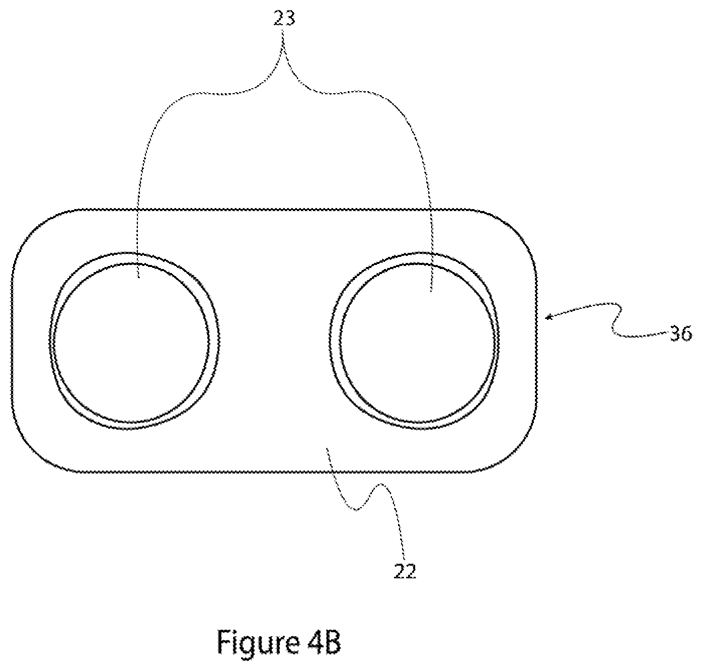
FIG. 4B is a top plan view of the rectangular piston of FIG. 4A.
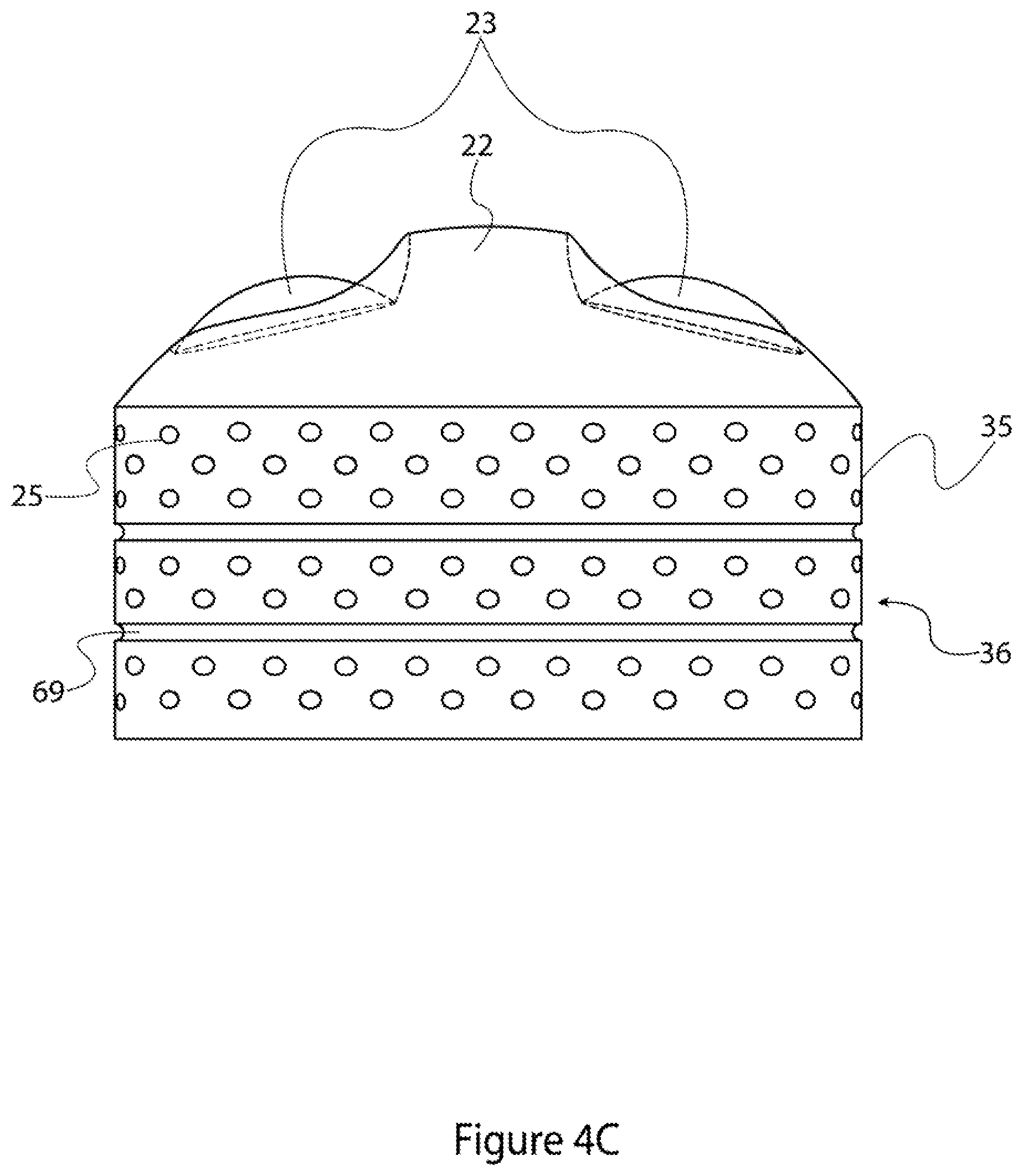
FIG. 4C is a side, partial cross-sectional, view of the rectangular piston of FIG. 4A.
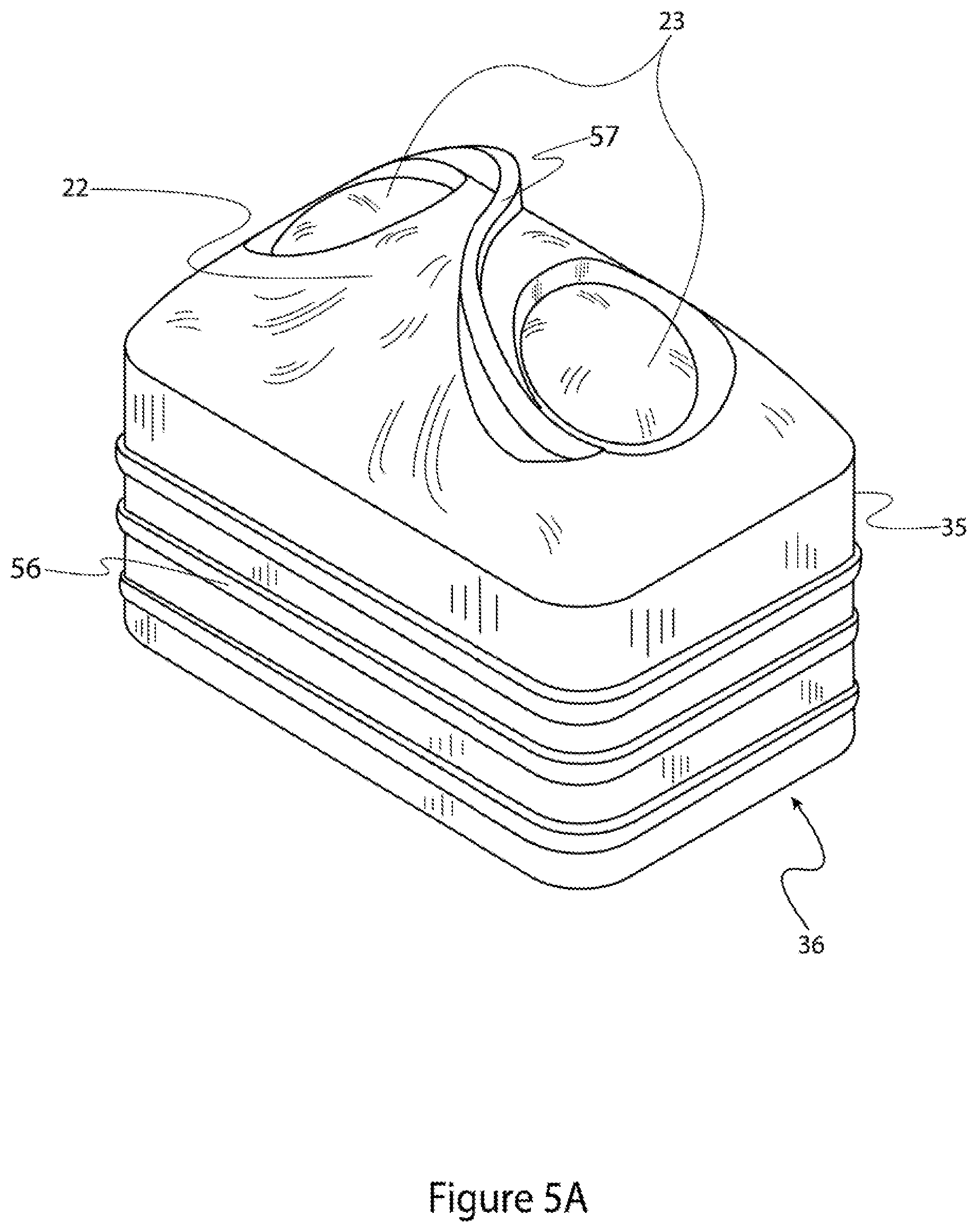
FIG. 5A is an isometric view of a rectangular piston for use in alternative embodiments of the present invention.
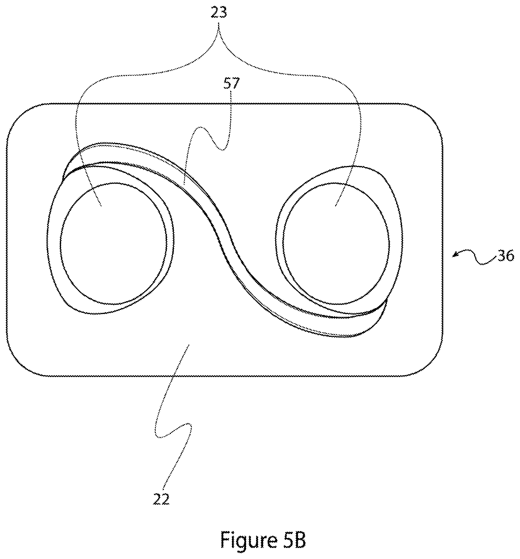
FIG. 5B is a top plan view of the rectangular piston of FIG. 5A.
FIG. 5C is a side, partial cross-sectional, view of the rectangular piston of FIG. 5A.
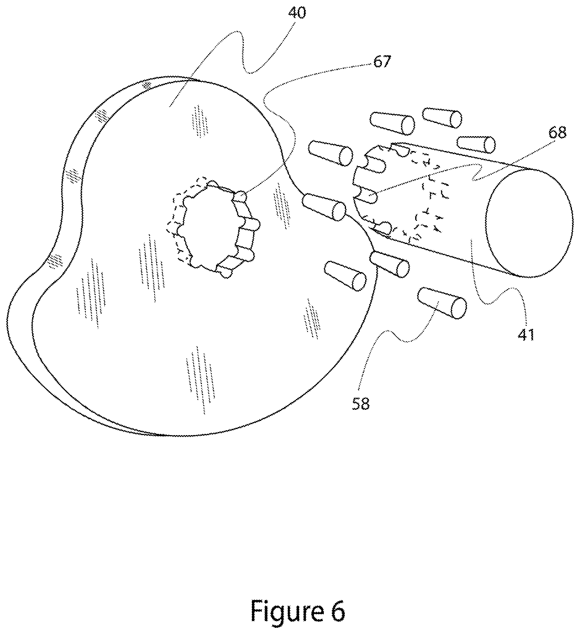
FIG. 6 is an exploded view of a crank, crankshaft, and joining elements in accordance with the first embodiment of the present invention.
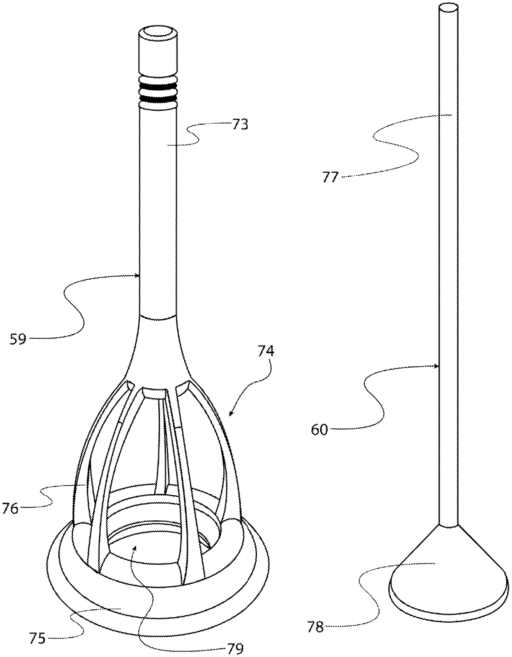
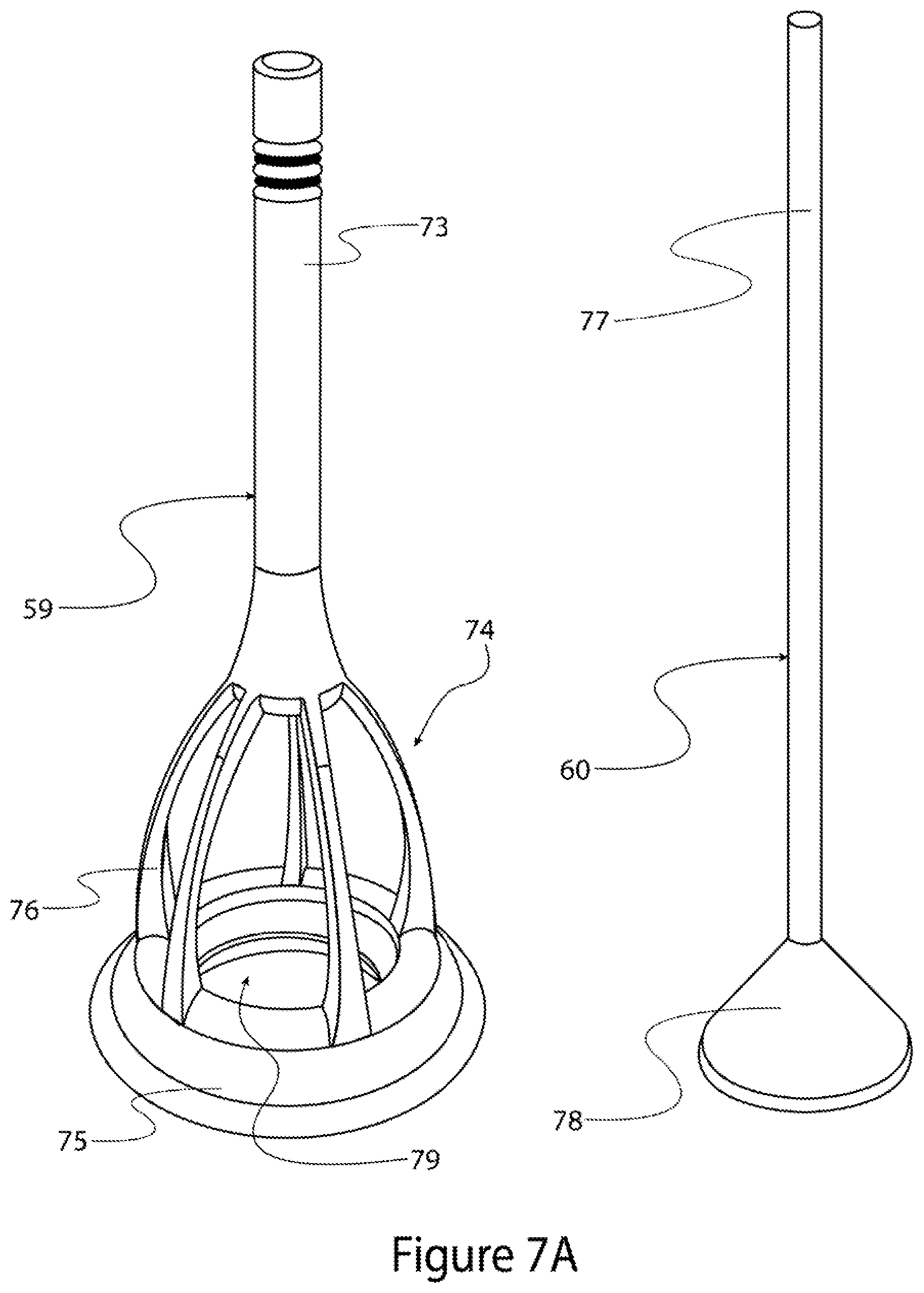
FIG. 7A is an isometric view of the separated outer and inner elements, respectively, of a multi-stage telescoping poppet valve in accordance with the first embodiment of the present invention.
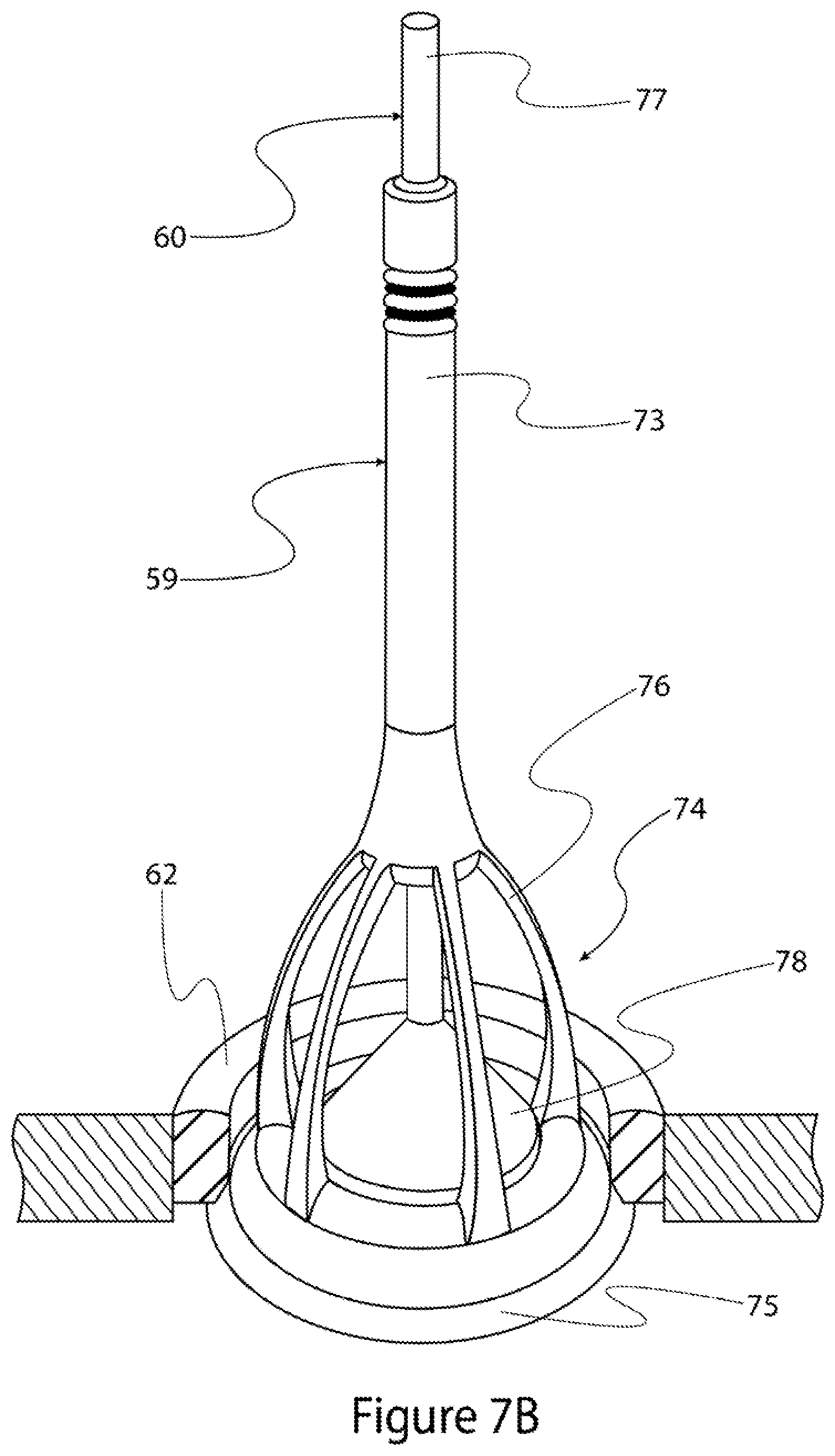
FIG. 7B is an isometric, partial cross-sectional, view of a multi-stage telescoping poppet valve constructed of outer and inner elements shown in FIG. 7A in a valve-closed position.
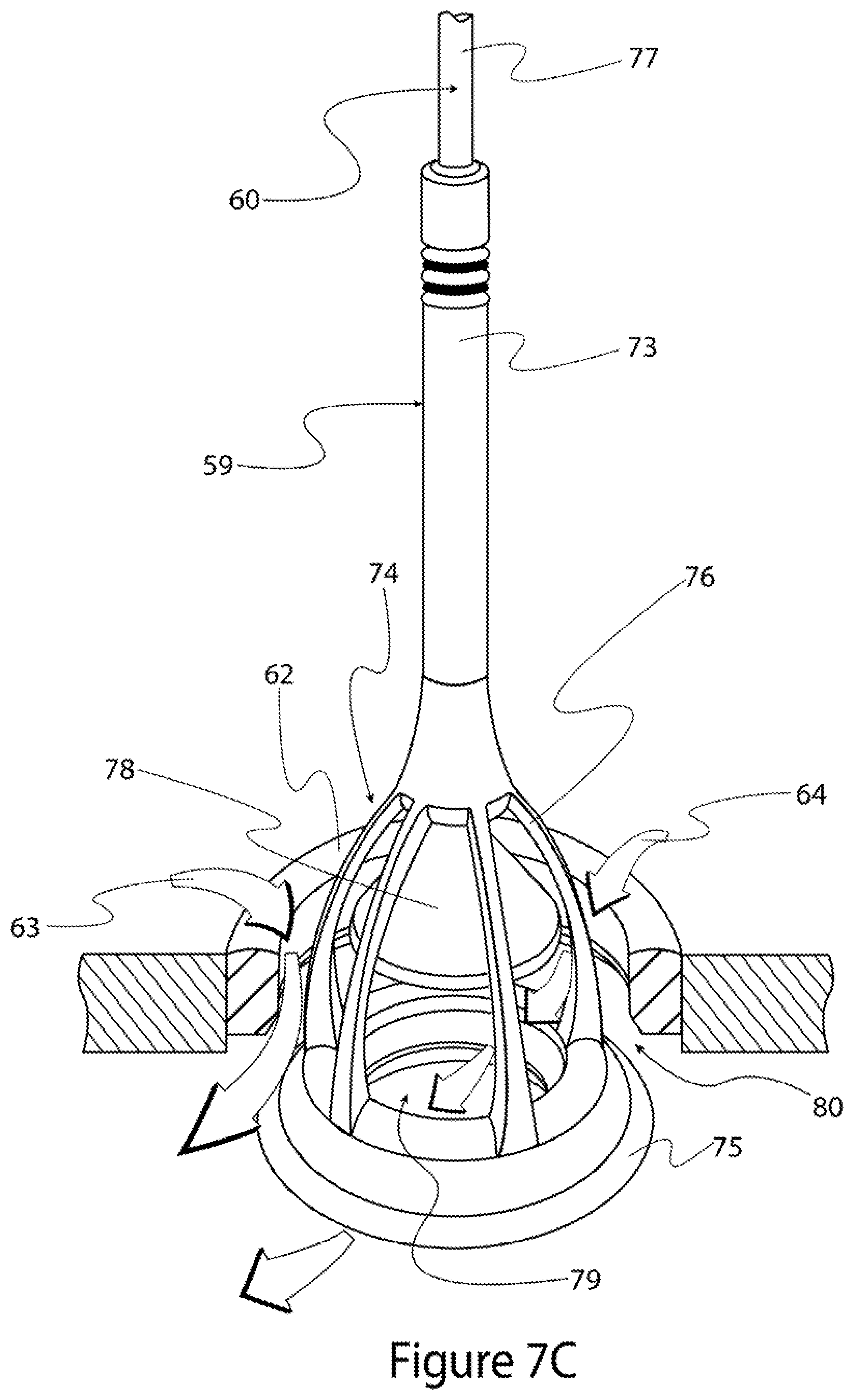
FIG. 7C is an isometric, partial cross-sectional, view of the multi-stage telescoping poppet valve of FIG. 7B in a valve-opened position.
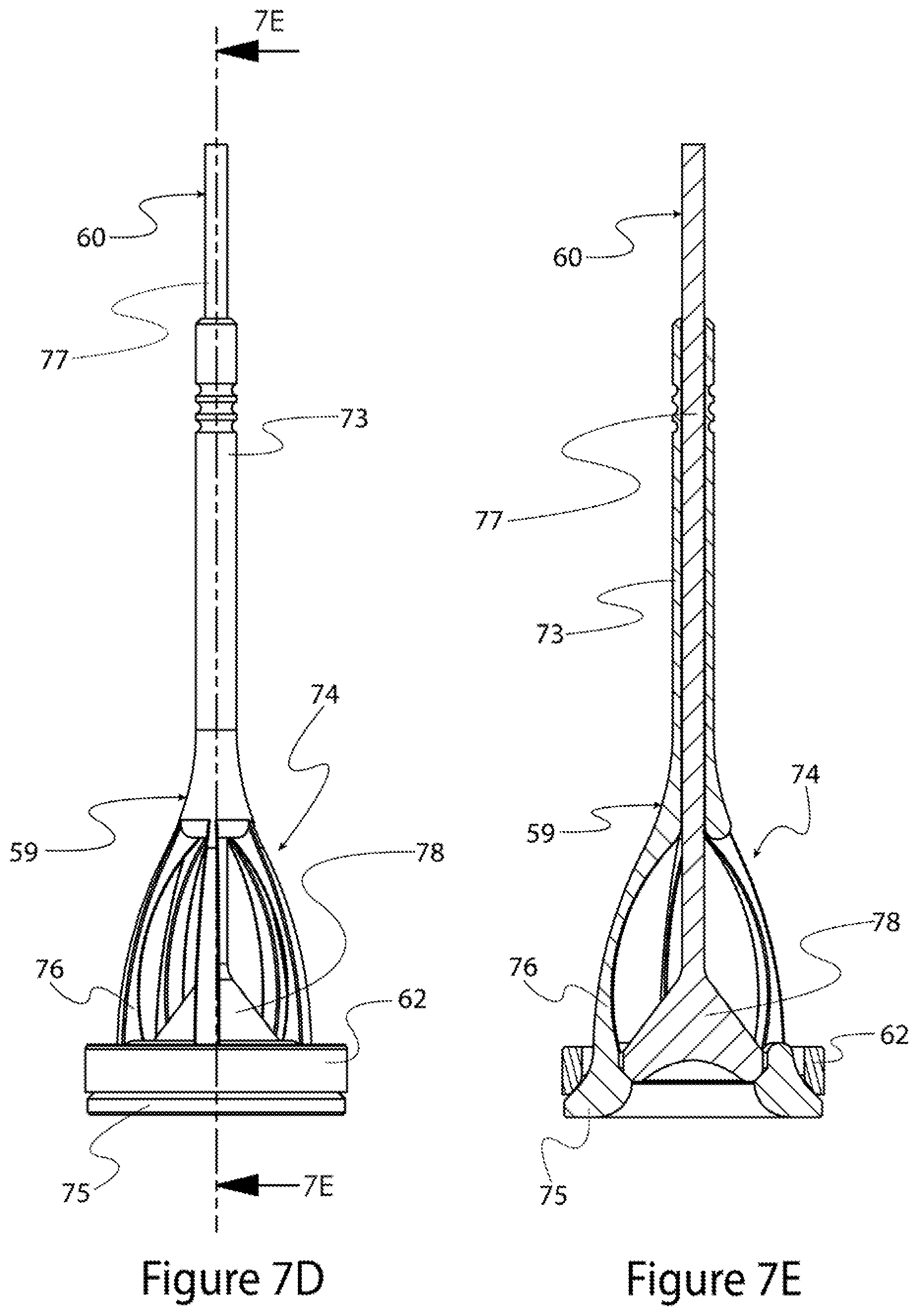
FIG. 7D is a side view of the multi-stage telescoping poppet valve of FIG. 7B.
FIG. 7E is a cross-sectional view of the multi-stage telescoping poppet valve of FIG. 7D.
FIG. 7F is an isometric view of the separated outer and inner elements, respectively, of a multi-stage telescoping poppet valve in accordance with a fourth embodiment of the present invention.
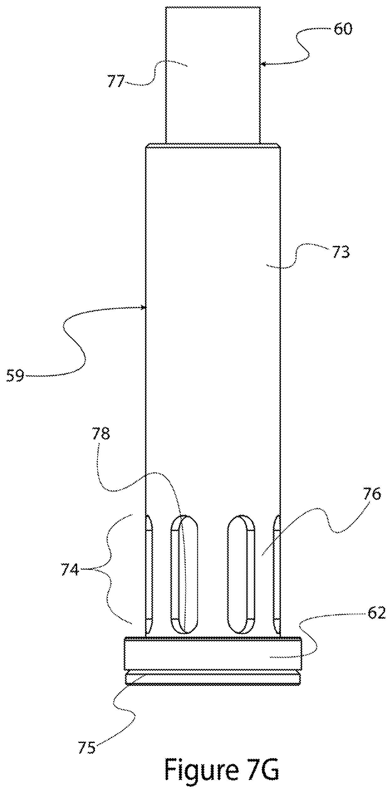
FIG. 7G is a side view of a multi-stage telescoping poppet valve constructed of outer and inner elements shown in FIG. 7F in a valve-closed position.
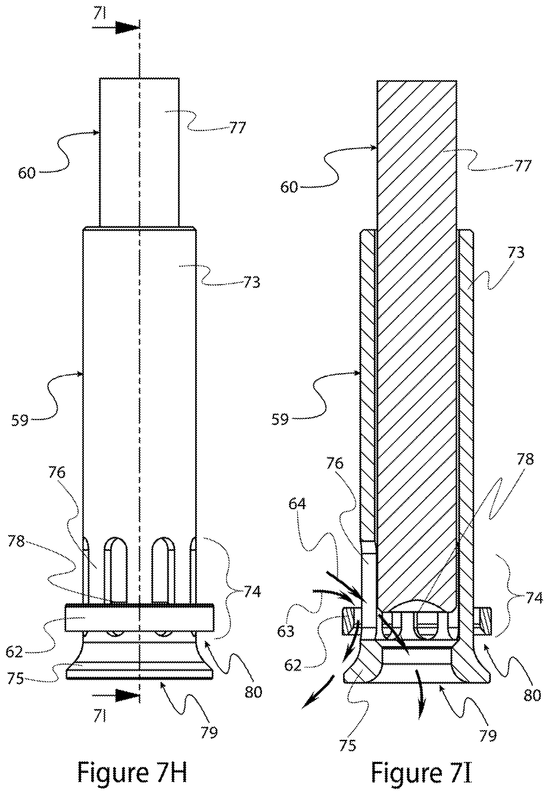
FIG. 7H is a side view of the multi-stage telescoping poppet valve of FIG. 7G in a valve-opened position.
FIG. 7I is a cross-sectional view of the multi-stage telescoping poppet valve of FIG. 7H.
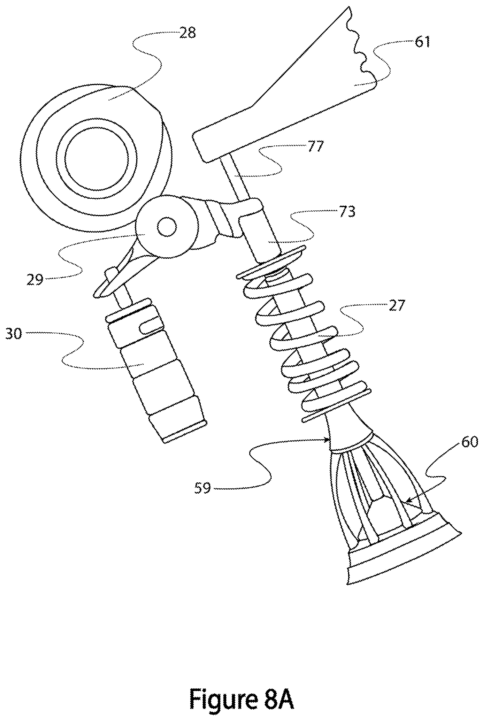
FIG. 8A is a side view of the poppet valve of FIGS. 7A-7E and a valve actuation system for the poppet valve in accordance with the first embodiment of the present invention.
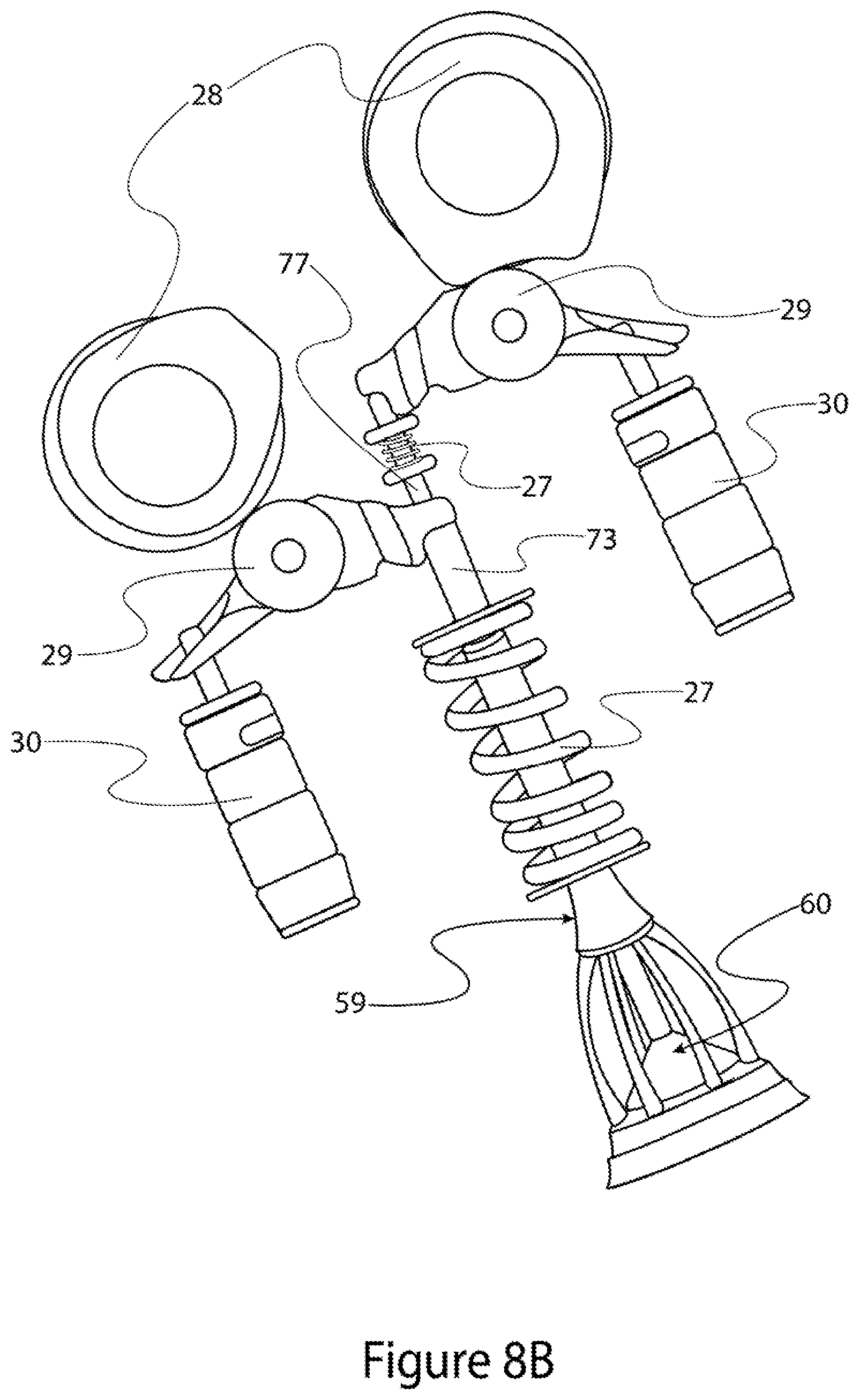
FIG. 8B is a side view of the poppet valve of FIGS. 7A-7E and a valve actuation system for the poppet valve in accordance with a fifth embodiment of the present invention.
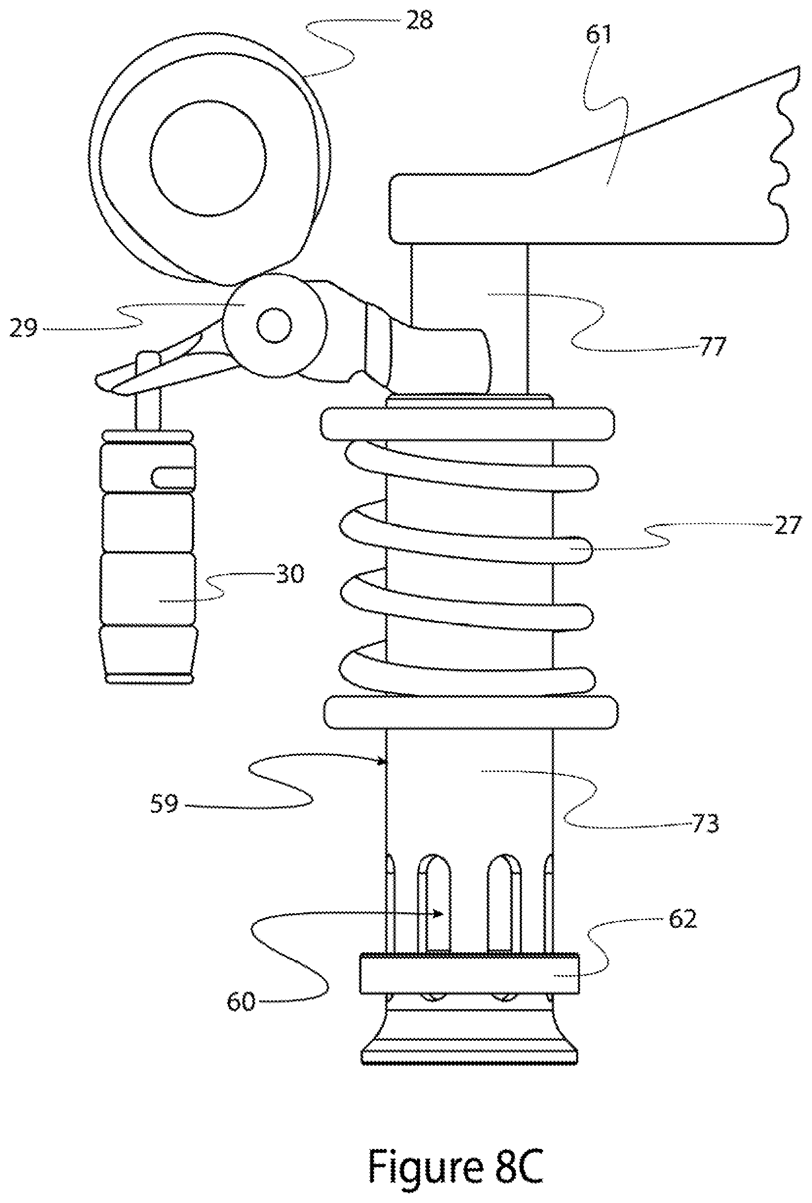
FIG. 8C is a side view of the valve actuation system of FIG. 8A used with a poppet valve of FIGS. 7F-7I.
FIG. 9 is a side view of an inverted orientation internal combustion engine in accordance with a sixth embodiment of the present invention.
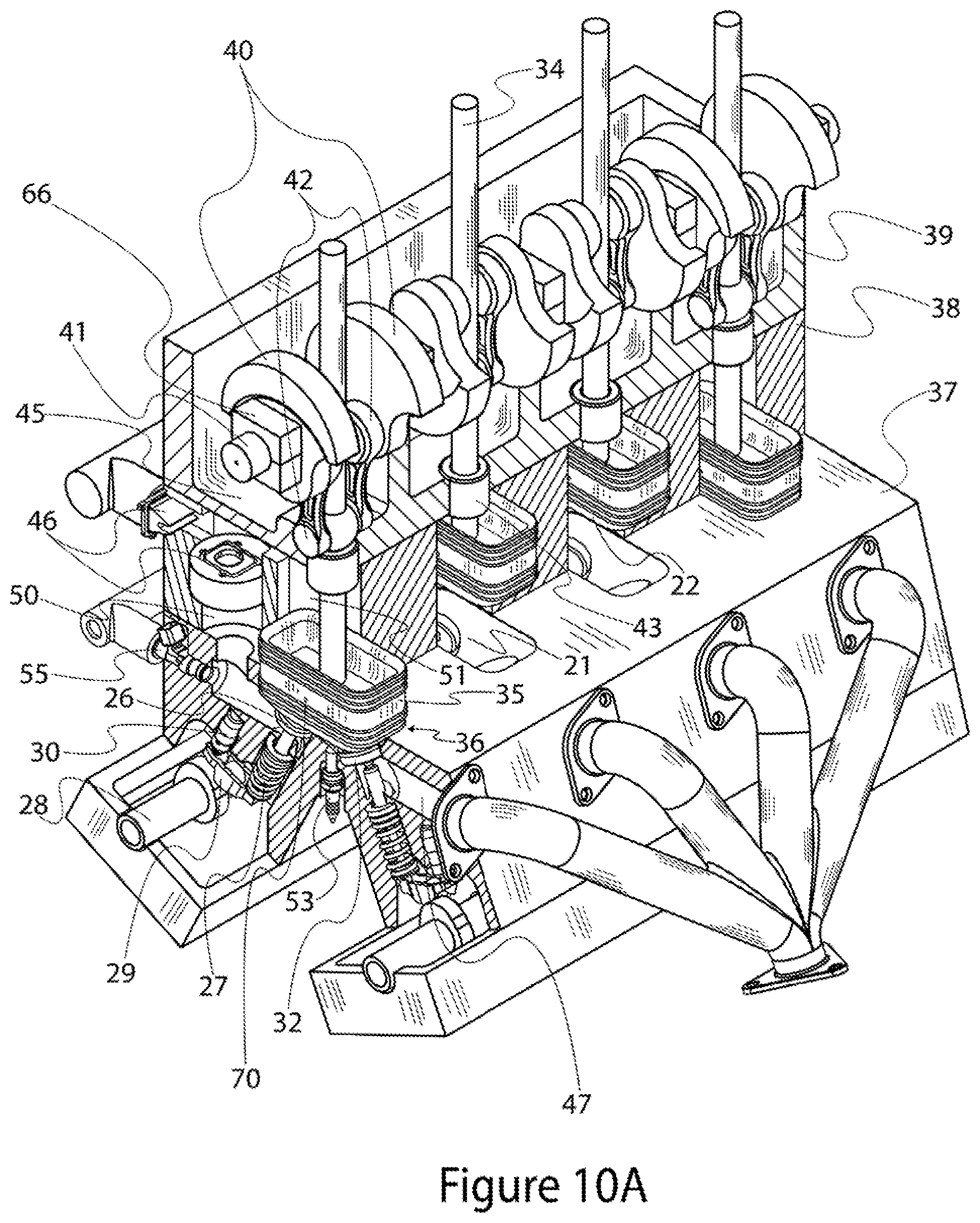
FIG. 10A is an isometric, partial cross-sectional, view of an inverted orientation internal combustion engine in accordance with a seventh embodiment of the present invention.
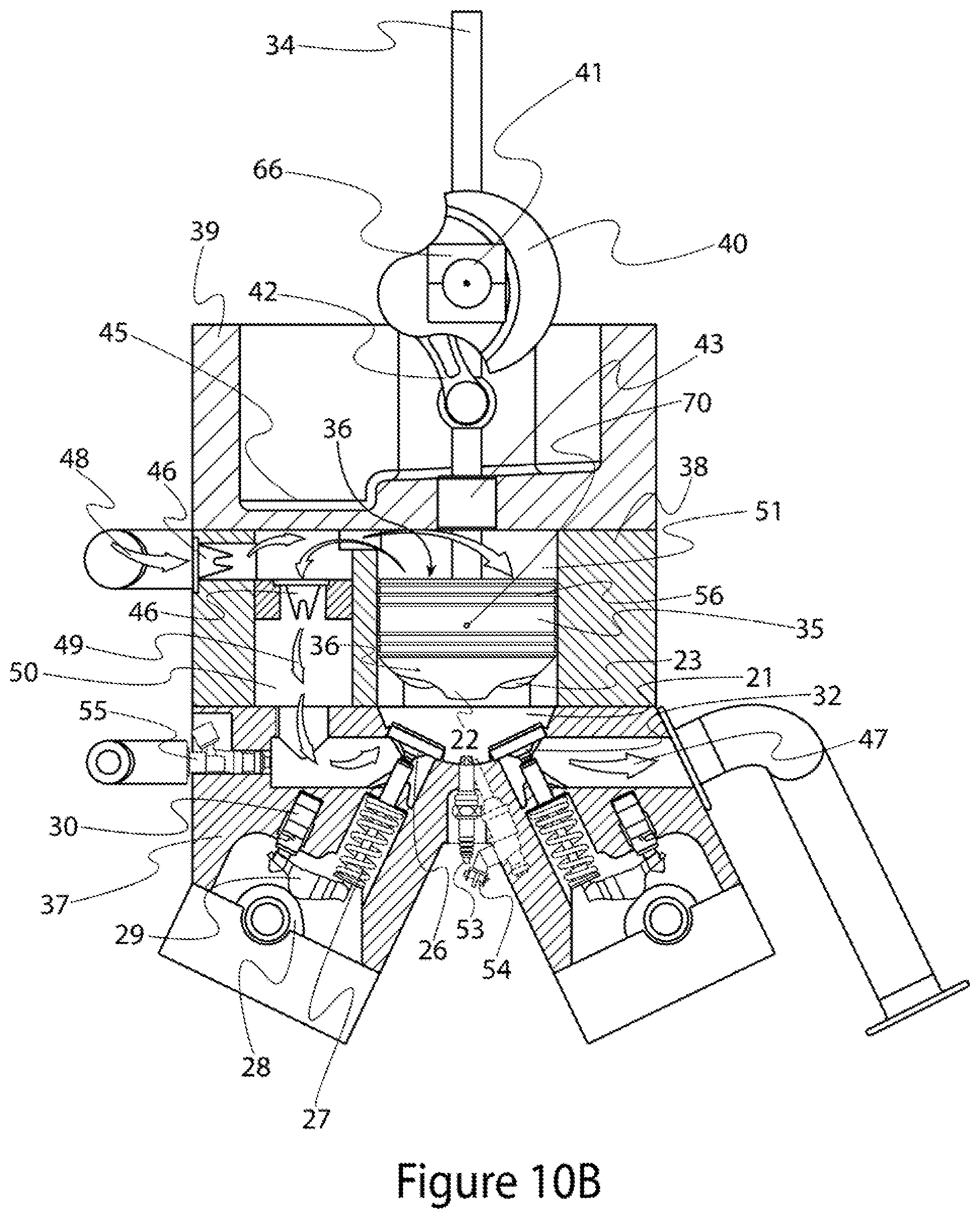
FIG. 10B is a cross-sectional end view of the internal combustion engine of FIG. 10A.
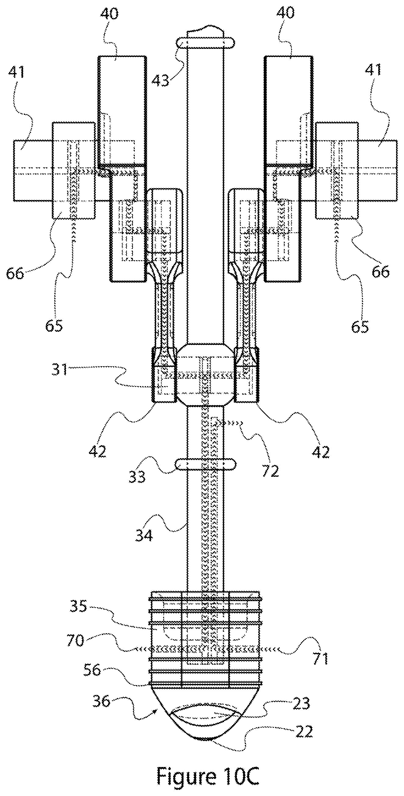
FIG. 10C is a side view of a lubricated engine piston and crankshaft arrangement shown in FIGS. 10A and 10B.
FIG. 10D is a top plan view of the engine piston shown in FIG. 10C.
DETAILED DESCRIPTION OF EMBODIMENTS OF THE INVENTION
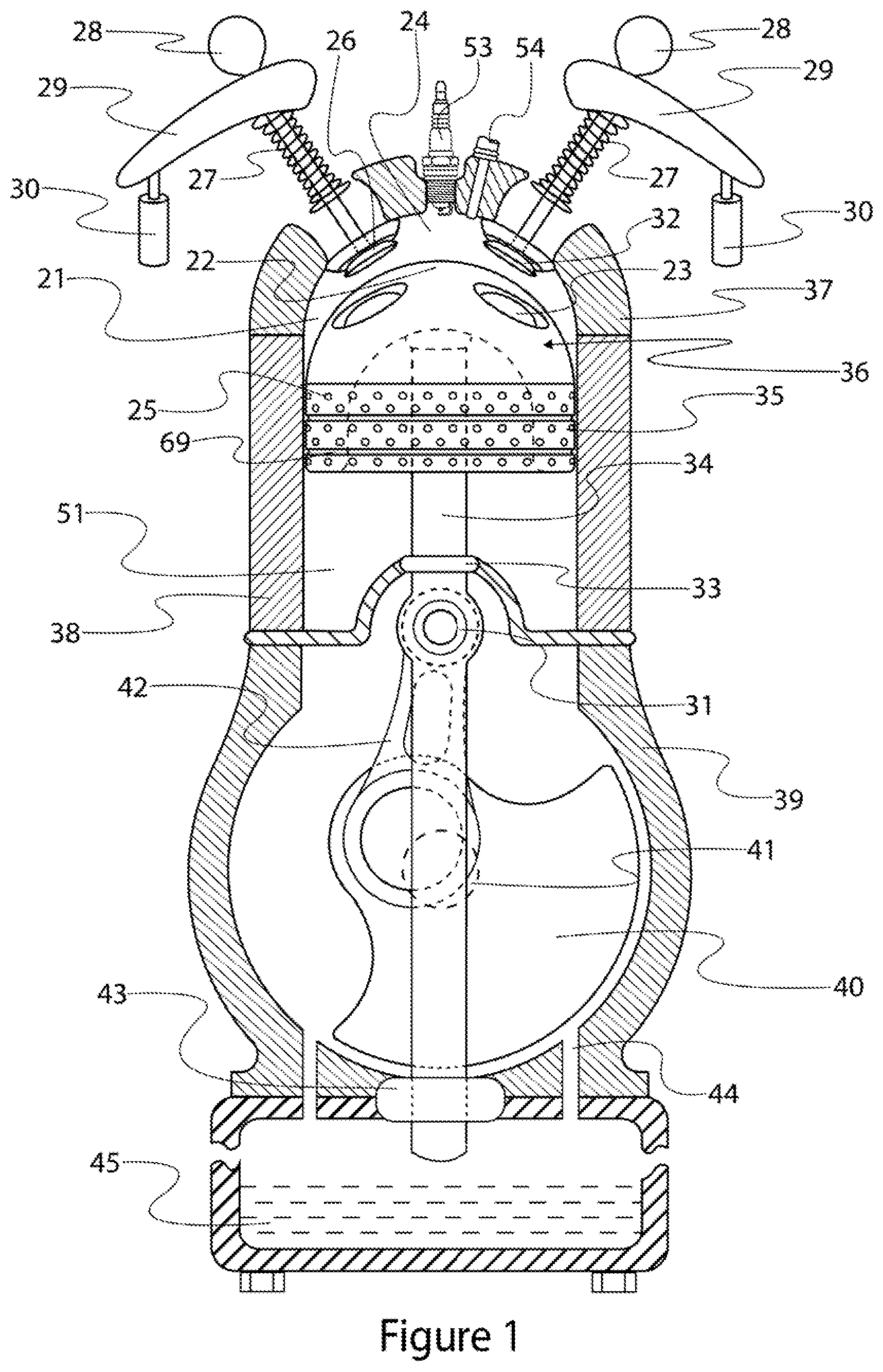
Reference will now be made in detail to embodiments of the present invention, examples of which are illustrated in the accompanying drawings. With reference to FIG. 1, an end-on partial cross-sectional view is provided of an engine piston 36, cylinder head 37, engine block 38, crankcase 39, and oil reservoir 45, in accordance with a first embodiment of the invention. The engine may be oriented with the cylinder head 37 at an upper end, i.e., with the center of mass of the cylinder head further away from the center of gravity of the local gravitationally dominant terrestrial body (e.g., Earth) than the center of mass of the engine block 38.
The cylinder head 37 may be sealed to the engine block 38. The upper wails of the cylinder head 37 and the engine block 38 define a combustion chamber 21 above the piston 36. The seal between the cylinder head 37 and the engine block 38 prevents or limits air or other gases from escaping from the combustion chamber 21. The cylinder head 37 may have a plurality of apertures provided in it to receive various engine components. A first aperture may provide an intake port that may be selectively blocked and unblocked by an intake poppet valve 26. A second aperture may provide an exhaust port that may be selectively blocked and unblocked by an exhaust poppet valve 32. A third aperture may receive a spark plug 53 for spark ignition engines, or a glow plug for Diesel engines. A fourth aperture may receive a direct fuel injector 54. Additional apertures may be provided in the cylinder head 37 for additional intake valves, exhaust valves, auxiliary valves, spark plugs, glow plugs, fuel injectors and/or water injectors. Preferably, the intake poppet valve(s) 26, exhaust poppet valve(s) 32, spark plug(s) 53, direct fuel injector(s) 54, and water injector (not shown), are provided at or near central locations of the cylinder head 37.
The elongated stems of the intake poppet valve 26 and the exhaust poppet valve may be biased toward their respective cam followers 29 by valve springs 27. The cam followers 29 may pivot about hydraulic lifters 30 under the influence of the cams 28. The hydraulic lifters 30 may be controlled to provide Variable Valve Actuation, although this is not required, in which case the hydraulic lifters may be used to simply adjust valve lash. The valve springs 27 may bias the intake and exhaust poppet valves 26 and 32 into closed positions when their respective cams 28 are at base circle with respect to the cam followers 29. It is appreciated that the foregoing described valve train arrangement may be modified without departing from the intended scope of the present invention. Different combinations of mechanical, electrical and/or hydraulic components may be employed to actuate the intake and exhaust poppet valves.
The piston 36 may be slidably disposed in the engine block 38 below the cylinder head 37. The piston 36 may have a piston head 22 at an upper end, a lower end, and a side wall or piston skirt 35 extending between the upper end and the lower end of the piston. The piston skirt 35 may be generally non-cylindrically shaped, and the piston head 22 may be domed cooperatively with the upper end wall of the combustion chamber 21. One or more depressions 23 may be formed in the piston head 22. When viewed from above, looking down into the combustion chamber 21, the outer perimeters of the piston skirt 35 and the piston head 22 may have a non-circular cross-sectional shape, preferably a generally rectangular shape with rounded corners. The cylinder may have a matching cross-sectional shape. The term "rectangular" refers to a shape with four straight edges joined at four rounded ninety-degree corners wherein there are at least two opposing pairs of straight edges that are the same length separated by rounded corners, or all four of the straight edges are the same length (square) separated by rounded ninety-degree corners. The dimension of the rounded corners may vary, and in some embodiments may occupy a dominant portion of the rectangle side.
The curvature of the outer surface of the piston head 22 may be preferably hemispherical or semi-hemispherical, and may have a substantially constant radius of curvature. The upper dome of the piston head 22 may extend between diametrically opposed edges of the piston skirt 35, and thus the diameters of the piston skirt 35 and the upper dome may be substantially the same. The upper dome may have an upper-most crown or apex that may be located at a point spaced from or coincident with a reference axial centerline extending through the centers of the upper dome and piston skirt 35. In other words, the apex may be off-center and proximal to the one side of the engine cylinder in which the piston 36 is disposed, or may be on-center relative to the engine cylinder.
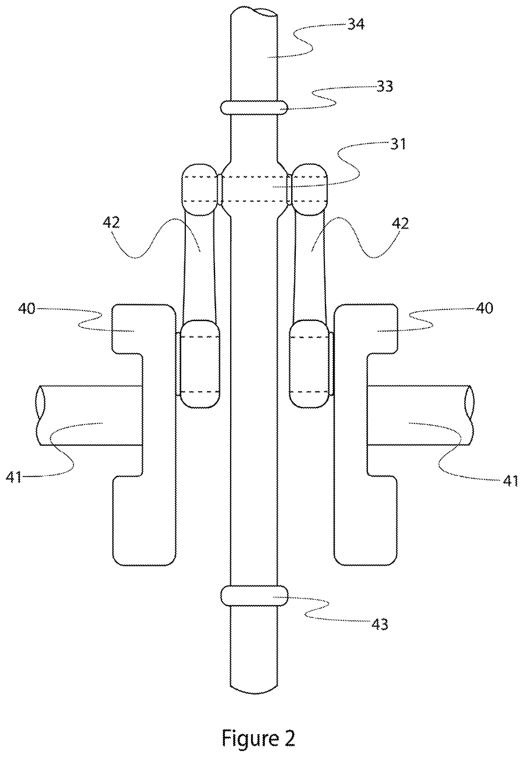
With reference to FIGS. 1 and 2, the piston 36 may be attached to a cross-head 34 which is slidably received by an upper cross-head guide 33 and a lower cross-head guide 43. The upper cross-head guide 33 and lower cross-head guide 43 constrain the cross-head 34 to purely linear motion. The lower portion of the cross-head 34 may extend past the lower cross-head guide 43 into the oil reservoir 45. Rapid dipping and unclipping of the cross-head 34 into the oil reservoir 45 may create oil splash that lubricates the engine components in the crankcase 39. The upper cross-head guide 33 may form a harrier that prevents oil from entering the lower (supercharger) chamber 51 from the crankcase 39, and that prevents gases in the lower chamber from entering the crankcase. One or more drain passages 44 may extend between the crankcase 39 and the oil reservoir 45.
With continued reference to FIGS. 1 and 2, the cross-head 34 may be pivotally connected to two connecting rods 42 by a wrist pin 31 located between the upper cross-head guide 33 and the lower cross-head guide 43. Each connecting rod 42 is aligned parallel with and rigidly connected to the other connecting rod by the wrist pin 31. The connecting rod 42 and wrist pin 31 may be connected using a weld, pin, press fit, interlocking shape, or locking screws, for example. The wrist pin 31 may have an axial dimension that is parallel with, but spaced from, an axial dimension of the crankshaft 41. The two connecting rods 42 may be disposed on opposite sides of the cross-head 34. The ends of the connecting rods 42 that are distal from the wrist pin 31 may be pivotally connected to respective cranks 40 disposed on opposite sides of the cross-head 34. Each of the cranks 40 may be connected to a split crankshaft comprised of two coaxial crankshaft sections 41 disposed on opposite sides of the cross-head 34. Each crank 40 may have an offset (i.e. the distance between (i) the pivot point of the crank 40 and connecting rod 42 and (ii) the axis of the crankshaft 41) equal to half of the appropriate stroke length of the piston 36.
FIG. 6 illustrates a preferred manner of connecting a crank 40 to a crankshaft section 41. The bore provided in the crank 40 for receiving the crankshaft 41 may have a plurality of crank keyholes 67 formed in the bore side wall. The crankshaft 41 may have a matching set of crankshaft keyholes 68 formed around the outer circumference of one end of the crankshaft. Pins/keys 58 may be inserted into either the crank keyholes 67 or the crankshaft keyholes 68, after which the crank 40 and crankshaft 41 may be press fit together to form a rigidly connected crank and crankshaft assembly. The number, size, shape, and material of the pins/keys 58 may be selected to allow the pins/keys to shear with acceptable damage if the assembly is subjected to detrimental levels of acceleration, deceleration, non-circular motion, or over-limit torque. Shearing pins/keys 58 may permit the connected crank 40 and crankshaft 41 to disengage and prevent transmission of unacceptable forces to other components in the engine and drive train. Shearing pins/keys 58 may allow the assembly to be more easily repaired with low cost parts after a failure.
It is appreciated that the engine shown in FIG. 1 may include conventional intake and exhaust poppet valves. However, FIGS. 7A-7E, inclusive, illustrate an alternative multi-stage engine poppet valve for use as the intake poppet valve(s) 26 and/or exhaust poppet valve(s) 32 in various embodiments of the present invention. With reference to FIG. 7A, the multi-stage poppet valve may include a cooperatively shaped and sized inner poppet valve 60 and an outer poppet valve 59. The outer poppet valve 59 may have an upper elongated hollow stem 73, a lower valve head/seat 75, and an intermediary cage body 74. The cage body 74 may include a plurality of fingers 76 that connect the upper elongated hollow stem 73 to the lower valve head/seat 75. The lower valve head/seat 75 of the outer poppet valve 59 may have a port or opening 79 extending through it from a lower face to the cage body 74. The inner poppet valve 60 may have an upper elongated stem 77 and a lower valve head 78.
With reference to FIGS. 7B, 7D and 7E, the stem 77 of the inner poppet valve 60 is configured to slide securely within the hollow stem 73 of the outer poppet valve 59. The head 78 of the inner poppet valve 60 is configured to seal against the head/seat 75 of the outer poppet valve 59 to block the port 79 when the inner poppet valve is in a valve-closed position. The head/seat 75 of the outer poppet valve 59 is configured to seal against the valve seat 62 to block the port 80 when the outer poppet valve is in a valve-closed position. When the outer poppet valve 59 and inner poppet valve 60 are in valve-closed positions, as shown, the flow of working fluid through ports 79 and 80 is prevented. The outer poppet valve 59 encompasses the inner poppet valve 60 and the outer poppet valve head/seat 75 mates with a sealing surface on the inner poppet valve head 78.
With reference to FIG. 7C, the outer poppet valve 59 and the inner poppet valve 60 are shown in a valve-opened position for the passage of working fluid past the valve. Actuation of the outer poppet valve 59 causes the outer poppet valve to translate downward away from the valve seat 62, and (optional) actuation of the inner poppet valve 60 causes it to translate upward away from the outer poppet valve head/seat 75. These actuations, together or independently, permit working fluid to flow past the valve as the result of an outer flow 63 and/or an inner flow 64.
The inner poppet valve 60 may be manufactured by forging using dies to obtain stronger structures and better grain orientation, or turned on a lathe, for example. The outer poppet valve 59 may be progressively forged as a flat piece and then forged and bent progressively until U-shaped similar to the way sheet metal parts are shaped into 3D structures. The inner poppet valve 60 and outer poppet valve 59 assembly may be completed by inserting the inner poppet valve into the U-shaped outer poppet valve and pressing it closed. The resulting seam may be left slightly open or welded followed by a grind and polish process.
Alternatively, the inner poppet valve 60 may be made of two or more pieces where the stem 77 is separate from the head 78, for example. The inner poppet valve head 77 piece or pieces may be inserted through openings in the outer valve 59 cage body 74 and connected to the inner poppet valve 60 stem 77 using threads, pins, press-fit, welding, or other connection type. In other alternative examples, the outer poppet valve 59 and inner poppet valve 60 assembly may be manufactured using a laser sinter (rapid manufacturing/3D print) process, or investment casting/lost wax process, or fine die casting using cores. Other methods of manufacturing the described multi-stage valve may be employed without departing from the intended scope of the invention.
FIG. 8A illustrates an example of a valve actuation system that may be used to actuate a multi-stage poppet valve having an outer poppet valve 59 and an inner poppet valve 60 in accordance with the first embodiment of the present invention. A hydraulic lifter 30 may be supported at a lower end by a fixed structure such as the cylinder head. The upper end of the hydraulic lifter 30 may pivotally support the first end of a cam follower 29. The cam follower 29 may contact the cam 28. The end of the cam follower 29 distal from the lifter 30 may contact the outer poppet valve stem 73 such that downward motion of the cam follower end pushes the outer poppet valve stem downward against the upward bias of the valve spring 27. The cam follower 29 end may be forked so that its downward motion does not cause the inner poppet valve stem 77 to move. The inner poppet valve 60, including its stem 77, may be held in a fixed position by a fixed mount 61.
The position of the pivot point between the lifter 30 and the cam follower 29 relative to the cam 28 may be adjusted during engine operation to adjust lash. The pivot point may also be adjusted rapidly on an engine cycle-to-cycle basis to provide variable valve actuation. When the pivot point is held in a fixed position, even if only briefly, rotation of the cam 28 pushes the cam follower 29 downward about the pivot point, which in turn pushes the outer poppet valve stem 73 downward. The downward motion of the outer poppet valve stem 73 pushes the valve head/seat 75 downward and away from the seat 62 and the inner poppet valve head 78 (see FIG. 7C). This manner of valve actuation may be used to provide any needed valve opening events.
With renewed reference to FIG. 1, the piston 36 may be disposed within the combustion chamber 21 such that the piston skirt 35 is closely aligned with, but uniformly spaced from and parallel to, the side wall of the combustion chamber. The upper end wall and side wall of the combustion chamber 21, together with the piston head 22, may form a working space or compression area 24 which may receive a working fluid. The piston 36 may be configured to slide within the combustion chamber 21, reciprocally towards and away from the combustion chamber 21 upper end wall.
With reference to FIGS. 1, 4A, 4B and 4C, the piston skirt 35 may have a ringless fluid sealing system 25 comprised of a plurality of recesses or pockets separated by lands forming a field of pockets. Preferably, the pockets may be of like shape and dimension in terms of shape at the mouth, shape at the base, height, width, diameter, depth, and/or volume. Preferably, the piston skirt 35 is a hollow wall structure (i.e., not solid between opposing outer points) and the pockets are formed in piston skirt but do not extend through the piston skirt to the hollow interior of the piston 36. The pockets in the field 25 may be arranged in at least one circumferential row, or more preferably, in a grid pattern consisting of two or more vertically spaced rows of pockets. The number, shape, size and arrangement of the lands and pockets in the field 25 shown in the drawing figures was selected for ease of discussion and illustration and is not considered limiting.
A seal or seal equivalent may be produced over the expanse of the piston skirt 35, from top to bottom, due to the presence of the pockets and lands arranged in an appropriate sealing system field 25 on the face of the piston skirt. The seal or its equivalent may be generated as the result of the pressure difference of the working fluid between the combustion chamber 21 and the lower chamber 51. As the piston 36 moves upward in the combustion chamber 21, the pressure and temperature of the working fluid in the working space 24 may rise and produce a working fluid pressure differential between the combustion chamber 21 and the lower chamber 51. This pressure differential may cause the working fluid in the space between the piston skirt 35 side wall and the chamber side wall, i.e., flow in the seal gap, to flow towards the lower chamber 51. Flow of the working fluid through the seal gap may induce a local Venturi effect at each pocket in the field 25, which may locally increase the speed and decrease the pressure of the working fluid. The speed and pressure change of the working fluid may be a function of the practical small clearance distance between the piston skirt 35 side wall and the combustion chamber 21 side wall.
With continued reference to FIGS. 1, 4A, 4B and 4C, the pockets preferably may have relatively sharp edges at the junction with the face of the piston skirt 35, i.e., at the junction with the lands. As the working fluid flows over the sharp edge of a pocket, a decrease in local pressure may occur due to turbulence. As a result, the working fluid may expand creating a momentary decrease in pressure and an increase of localized turbulence. Further working fluid flowing over and into each successive pocket may begin a cycle wherein each pocket serves as a Helmholtz-like resonator or resonating column (dependent upon pocket shape deployed), which may cause the working fluid to be drawn into and expelled out of the pocket at a definable frequency creating further localized turbulence.
The resulting turbulence may be a function of the physical properties of the working fluid in the system and the diameter (or height and width), geometry, relational location, and depth of each individual pocket in the field 25. The resulting turbulence may also be a function of the practical small clearance distance or seal gap due to the ratio of the spatial volume above each land to the spatial volume above and within each pocket. This localized turbulence may interact with the flowing working fluid and generate a vortex motion that impedes further flow of the working fluid. The decrease in flow may momentarily decrease the resonance effect, which in turn may momentarily decrease the localized turbulence, which then may allow the flow rate of the working fluid to momentarily increase again.
When the piston 36 is on an upward stroke, the working fluid which has passed over the pockets in the upper most row (closest to the piston head 22) may next encounter the pockets in the adjacent row of the pocket field 25 where the described turbulence phenomena repeats, but at a lower starting pressure. This process may repeat as the working fluid passes over successive rows of the sealing system pocket field 25 with successively relatively decreased starting pressure until the local pressure in the seal gap is reduced to the pressure level of the working fluid contained in the lower chamber 51. The repeating cycle of pressure reduction from pocket to pocket in the field 25 may create a seal or the effective equivalent of a seal since no working fluid will flow past the point at which the local pressure in the seal gap is at or below the pressure of the working fluid in the lower chamber 51.
The localized turbulence at each pocket may decrease with time due to the gradual leaking allowed by the resonant action of the pockets. Therefore, the localized turbulence may also be a function of the rate of motion of the piston 36 relative to the combustion chamber 21 side wall, as the motion may be responsible for the pressure changes around the piston 36 in the combustion chamber. The effectiveness of the sealing system may require working fluid pressures that fluctuate to provide energetic flows into the sealing system field 25 by providing a consistent flow in and out of the pockets, thereby maintaining the effectiveness of the sealing system.
The rate of the sealing system leakage may be modified by using different land spacing patterns and pocket geometries within the sealing system field 25. The land spacing may be selected to induce the pockets to provide counter flow to prior (upper) pockets while forward (lower) pockets may prevent fluid flow to induce internally decaying self-reinforcing oscillations within the sealing system field 25.
The effectiveness of the sealing system field 25 for a particular application may be a function of the outside dimensions of the sealing system field in addition to the design parameters of the individual pockets. The seal efficiency may be improved by modifying the geometry of some or all of the pockets to include a convergent area at the inner base of the pockets and a divergent area at the mouth of the pockets. A de Laval nozzle effect may be produced at the pockets using a convergent area and a larger divergent area to form a resonant cavity at the bottom of the pockets, which may create greater localized turbulence due to localized supersonic working fluid movement.
With reference to FIG. 1, the piston 36 may self-center within the combustion chamber 21 due to the tendency of the pressure surrounding the piston to normalize at any given vertical point on the piston skirt 35. For example, when the practical small clearance distance, i.e., the seal gap, between the piston 36 and the surrounding cylinder are momentarily unequal about a central axis, a total normalizing force may be generated by the pressures acting on the surface area of the opposing sides of the piston. This total normalizing force may urge the piston 36 to be centrally located within the cylinder with a dampened oscillation about the central axis. With additional reference to FIGS. 4A and 4C, the time required for the normalizing force to return the piston to the center of the cylinder may be decreased by adding one or more equalizing grooves 69. The equalizing grooves 69 may be disposed on land areas, or between pockets, or both on land areas and between pockets, or in the side wall of the chamber 21 opposing the pockets to allow a more uniform distribution of the forces more rapidly on the surface employing the sealing system.
It is appreciated that the field 25 of pockets, and/or the equalizing grooves 69, described as being formed on or in the surface of the piston 36 may instead be formed on or in the surface opposing the piston in alternative embodiments. It is also appreciated that the field 25 of pockets described as being formed on or in the surface of the piston 36 may also be formed on or in the surface opposing the piston in addition to being formed on or in the surface of the piston. It is also appreciated that the field of pockets may be used on pistons like those illustrated in FIGS. 4A, 4B and 4C, or on other pistons of different (i.e., non-rectangular) shape, with or without depressions 23.
With reference to FIGS. 1, 4A, 4B and 4C, details of the depressions 23 formed in the piston 36 are illustrated. There may be one depression 23 (left side of figure) provided for a corresponding intake poppet valve 26 and another depression 23 (right side of figure) provided for a corresponding exhaust poppet valve 32. The depressions 23 may each have a continuous, generally circular, side wall extending between an upper lip and a depression floor. Each of the depression side walls may be curved in two dimensions--from upper lip to depression floor, and in a plane substantially parallel to the depression floor so as to be generally circular when viewed from above. Alternatively, the side walls may be ramped in the floor to upper lip dimension instead of curved in that direction. The height of the depression side walls (i.e., the vertical distance between the upper lip and the depression floor) may vary along its length, preferably having a maximum height at a point proximal to the center of the piston 36 and a minimum height at a point distal from the center of the piston. The curved shape of the depression 23 side walls in the upper lip to depression floor direction may vary, but is preferably spherical. The depression floors may be generally flat or curved to a lesser degree than the side walls. The size of the depressions 23 may also vary, but preferably the depressions have a larger diameter at the upper lip than at the depression floor, i.e., the length of the side wall at a junction of the side wall with the upper lip is greater than the length of the side wall at a junction of the side wall with the depression floor.
The depression floor of each depression 23 may be set at an angle relative to the straight edge formed by the junction of the piston skirt 35 with the piston head 22, as shown in FIG. 4C. The angle at which the depression floor is set may match
References
D00000
D00001
D00002
D00003
D00004
D00005
D00006
D00007
D00008
D00009
D00010
D00011
D00012
D00013
D00014
D00015

D00016
D00017
D00018
D00019
D00020
D00021

D00022
D00023
D00024
D00025

XML
uspto.report is an independent third-party trademark research tool that is not affiliated, endorsed, or sponsored by the United States Patent and Trademark Office (USPTO) or any other governmental organization. The information provided by uspto.report is based on publicly available data at the time of writing and is intended for informational purposes only.
While we strive to provide accurate and up-to-date information, we do not guarantee the accuracy, completeness, reliability, or suitability of the information displayed on this site. The use of this site is at your own risk. Any reliance you place on such information is therefore strictly at your own risk.
All official trademark data, including owner information, should be verified by visiting the official USPTO website at www.uspto.gov. This site is not intended to replace professional legal advice and should not be used as a substitute for consulting with a legal professional who is knowledgeable about trademark law.