Hinge-latch combination
Cifers , et al.
U.S. patent number 10,590,687 [Application Number 16/030,682] was granted by the patent office on 2020-03-17 for hinge-latch combination. This patent grant is currently assigned to Luther Cifers. The grantee listed for this patent is Luther Cifers. Invention is credited to Luther Cifers, Matthew Montaruli, Hans Nutz.


| United States Patent | 10,590,687 |
| Cifers , et al. | March 17, 2020 |
Hinge-latch combination
Abstract
A combination hinge and latch that enables a door, gate or lid to be opened from a latched side and latched from the hinged side to provide more than one point of access for an area behind the door, gate or lid.
| Inventors: | Cifers; Luther (Amelia, VA), Montaruli; Matthew (Greenville, SC), Nutz; Hans (Easley, SC) | ||||||||||
|---|---|---|---|---|---|---|---|---|---|---|---|
| Applicant: |
|
||||||||||
| Assignee: | Cifers; Luther (Amelia,
VA) |
||||||||||
| Family ID: | 69779050 | ||||||||||
| Appl. No.: | 16/030,682 | ||||||||||
| Filed: | July 9, 2018 |
Related U.S. Patent Documents
| Application Number | Filing Date | Patent Number | Issue Date | ||
|---|---|---|---|---|---|
| 62530294 | Jul 10, 2017 | ||||
| Current U.S. Class: | 1/1 |
| Current CPC Class: | E05D 7/1061 (20130101); E05D 7/12 (20130101); E05D 7/1066 (20130101); E05D 7/1022 (20130101); E05D 11/1014 (20130101); E05D 15/50 (20130101); E05Y 2900/40 (20130101); E05Y 2900/132 (20130101); E05D 15/505 (20130101); Y10T 16/528 (20150115); E05D 7/1077 (20130101); E05D 2007/128 (20130101) |
| Current International Class: | E05D 7/12 (20060101); E05D 7/10 (20060101); E05D 11/10 (20060101); E05D 15/50 (20060101) |
References Cited [Referenced By]
U.S. Patent Documents
| 114579 | May 1871 | Marston |
| 479936 | August 1892 | Foster |
| 935087 | September 1909 | Bloomer |
| 2365378 | December 1944 | Benson |
| 2656562 | October 1953 | Phillips |
| 2799324 | July 1957 | Anderson |
| 2926382 | March 1960 | Knese |
| 3091357 | May 1963 | Weinhart |
| 3805325 | April 1974 | Lee |
| 3825296 | July 1974 | Peterson |
| 3922870 | December 1975 | Recalde |
| 4613174 | September 1986 | Berg |
| 4731903 | March 1988 | Kennedy |
| 5381920 | January 1995 | Lin |
| 5548927 | August 1996 | Song |
| 5675934 | October 1997 | Park |
| 5829197 | November 1998 | Oh |
| 6000550 | December 1999 | Simpson |
| 6105809 | August 2000 | Yamanaka |
| 6890196 | May 2005 | Vila |
| 7100786 | September 2006 | Smyers |
| 7116559 | October 2006 | Davis, Jr. |
| 7574773 | August 2009 | Dahl |
| 7761958 | July 2010 | Alfredsson |
| 8024839 | September 2011 | Lewis, II |
| 8272101 | September 2012 | Wagner |
| 8656556 | February 2014 | Bennett |
| 8727165 | May 2014 | Nolan |
| 9664215 | May 2017 | Laird |
| 10260262 | April 2019 | Jiang |
| 2007/0089269 | April 2007 | Shen |
| 2017/0044809 | February 2017 | Chiste |
Attorney, Agent or Firm: Hitaffer; Thedford I. Hitaffer & Hitaffer, PLLC
Parent Case Text
CROSS-REFERENCE TO RELATED APPLICATIONS
This application claims the benefit of U.S. Provisional Application No. 62/530,294, filed Jul. 10, 2017, the disclosure of which is incorporated herein by reference by its entirety.
Claims
What is claimed is:
1. A hinge-latch combination comprising: a lower mount configured to attach to a first structure, the lower mount comprising a longitudinally extending base and laterally disposed upwardly extending members, together with bridging structure, defining a semi-cylindrical well, hinge caps disposed on opposing ends of the lower mount, the hinge caps each comprising a cylindrical receptacle, which are opposingly disposed to face one another, a cradle supported in relation to the hinge caps, the cradle comprising two longitudinally disposed semi-cylindrical members each having an end received by the cylindrical receptacle of a corresponding one of the hinge caps far pivotal movement into the cylindrical receptacle of the corresponding one of the hinge caps, the cradle comprising a longitudinal opening, the semi-cylindrical members being longitudinally spaced apart so that the semi-cylindrical well is disposed therebetween, an upper mount configured to attach to a second structure, releasably coupled for hinged movement in relation to the cradle, the upper mount comprising a pin that is sized and configured to fit snugly for pivotal movement in the semi-cylindrical members and the semi-cylindrical well, and a latch clip joining the semi-cylindrical members, the latch clip being operable to move the longitudinal opening into alignment with the semi-cylindrical well for receiving and removing the pin from the semi-cylindrical members and the semi-cylindrical well and to move the longitudinal opening out of alignment with the semi-cylindrical well for containing the pin in the semi-cylindrical members and the semi-cylindrical well.
2. The hinge-latch combination of claim 1, wherein the upper mount further comprises longitudinally spaced legs that extend radially from the pin, the legs being longitudinally spaced with the semi-cylindrical well between the legs and the semi-cylindrical members being disposed on opposing sides of the legs.
3. The hinge-latch combination of claim 2, wherein the upper mount comprises a mounting plate that is supported in relation to ends of the legs opposite the pin.
4. The hinge-latch combination of claim 3, wherein the pin, the legs and the mounting plate are joined together to form a one-piece unitary construction.
5. The hinge-latch combination of claim 3, wherein the hinge caps and the mounting plate are provided with through slots for receiving fasteners for attaching the hinge caps and the mounting plate to respective supporting surfaces.
6. The hinge-latch combination of claim 2, wherein the legs are provided with a relief for receiving the latch clip in a snap fit fashion, wherein the latch clip is configured to be dislodged from the relief by applying sufficient force against the latch clip, and wherein with the latch clip dislodged, the cradle is configured to be pivoted to expose the longitudinal opening to permit the pin to be removed from the semi-cylindrical members and the semi-cylindrical well.
Description
BACKGROUND OF THE INVENTION
This invention relates in general to latches and hinges. Most particularly, the invention relates to a combination hinge and latch.
Hinges and latches are well known. A hinge is a movable joint on which a door, gate or lid moves or swings when opened and closed, or which otherwise connects objects for movement in relation to one another. A latch is a catch, lever or fastener used for fastening a door, gate or lid. It may be desirable to open a door, gate or lid from a latched side and latch the same from the hinged side.
A combination hinge and latch is needed that enables a door, gate or lid to be opened from a latched side and latched from the hinged side to permit access to an area behind the door, gate or lid from more than one point of access.
SUMMARY OF THE INVENTION
This invention relates to a combination hinge and latch that enables a door, gate or lid to be opened from a latched side and latched from the hinged side to provide more than one point of access for an area behind the door, gate or lid.
Various advantages of this invention will become apparent to those skilled in the art from the following detailed description of the preferred embodiment, when read in light of the accompanying drawings.
BRIEF DESCRIPTION OF THE DRAWINGS
Various features and attendant advantages of the hinge-latch combination will become more fully appreciated when considered in view of the accompanying drawings, in which like reference characters designate the same or similar parts and/or features throughout the several views, and wherein:
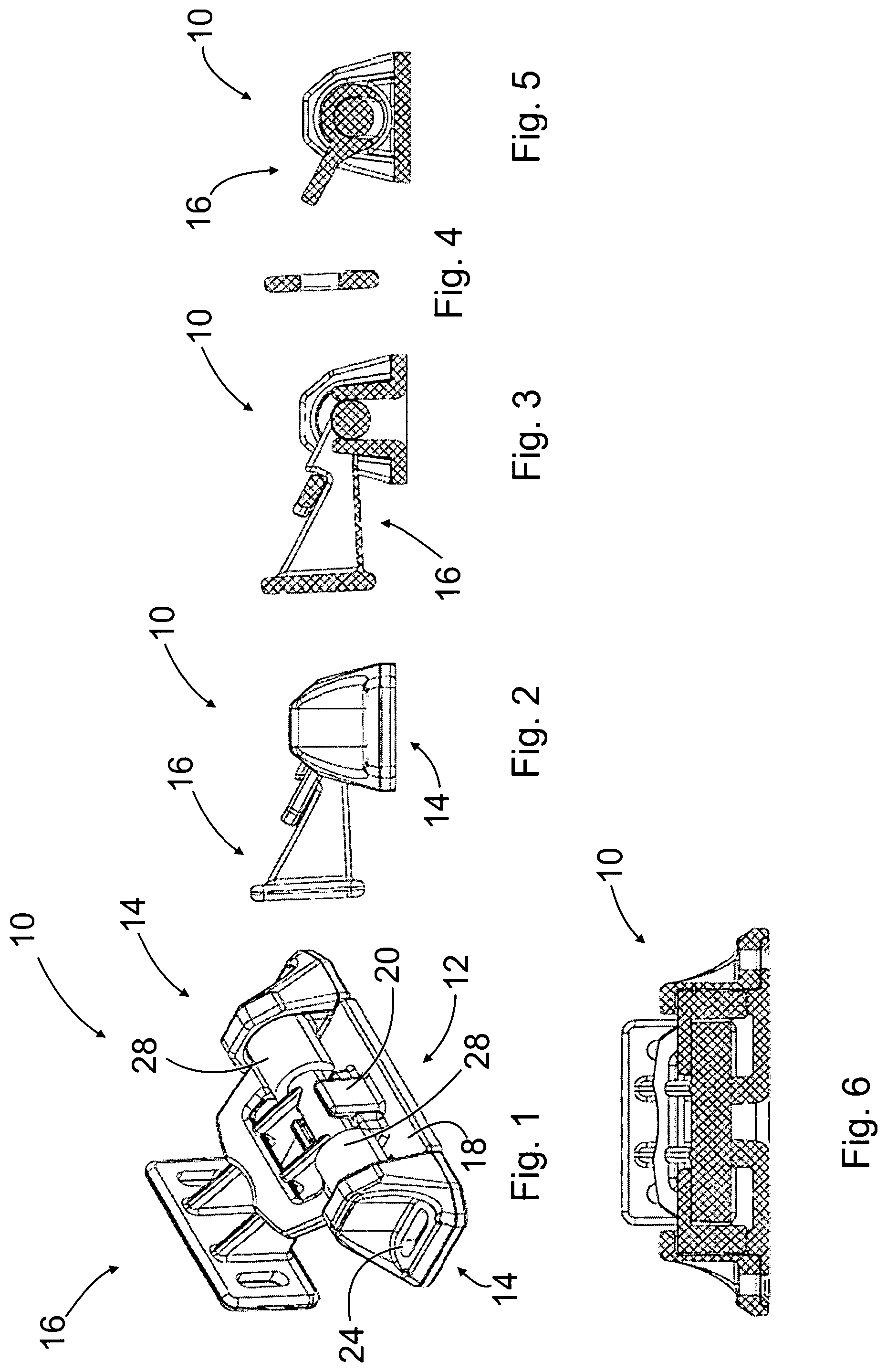
FIG. 1 is a front perspective view of an exemplary hinge-latch combination, in a latched condition;
FIG. 2 is a side elevational view of the hinge-latch combination shown in FIG. 1;
FIG. 3 is a cross-section view of the hinge-latch combination shown in FIG. 1 taken laterally through the center thereof.
FIG. 4 is a cross-section view of the hinge-latch combination.
FIG. 5 is a cross-section view of the hinge-latch combination shown in FIG. 1 taken laterally through the semi-cylindrical member thereof.
FIG. 6 is a cross-section view of the hinge-latch combination shown in FIG. 1 taken longitudinally through the center thereof.
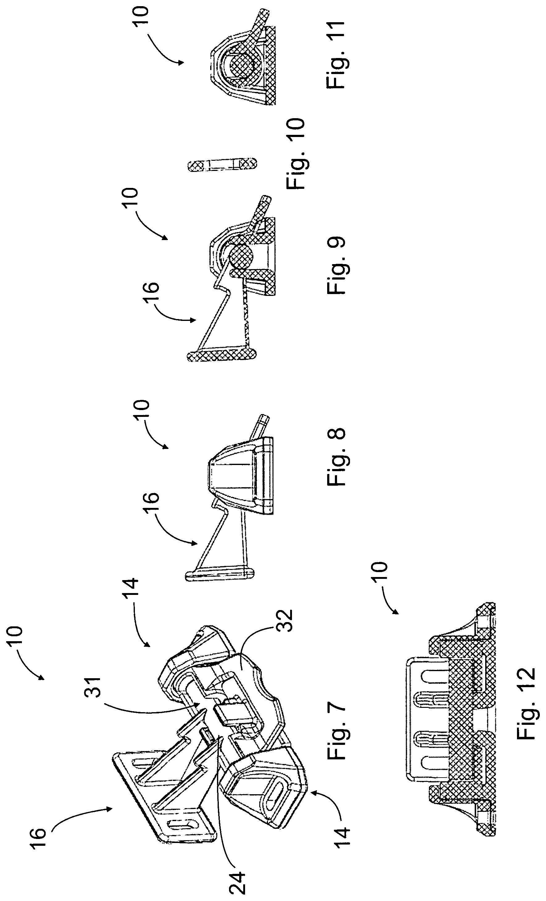
FIG. 7 is a front perspective view of the hinge-latch combination, in an unlatched condition;
FIG. 8 is a side elevational view of the hinge-latch combination shown in FIG. 8;
FIG. 9 is a cross-section view of the hinge-latch combination shown in FIG. 8 taken laterally through the center thereof.
FIG. 10 is a cross-section view of the hinge-latch combination.
FIG. 11 is a cross-section view of the hinge-latch combination shown in FIG. 8 taken laterally through the semi-cylindrical member thereof.
FIG. 12 is a cross-section view of the hinge-latch combination shown in FIG. 8 taken longitudinally through the center thereof.
FIG. 13 is a front perspective view of the hinge-latch combination, in a latched condition, in a first position;
FIG. 14 is a side elevational view of the hinge-latch combination shown in FIG. 13;
FIG. 15 is a front perspective view of the hinge-latch combination, in a latched condition, in a second position;
FIG. 16 is a side elevational view of the hinge-latch combination shown in FIG. 15;
FIG. 17 is a front perspective view of the hinge-latch combination, in an unlatched, exploded condition;
FIG. 18 is a side elevational view of the hinge-latch combination shown in FIG. 17; and
FIG. 19 is an environmental perspective view of the hinge-latch combination.
DETAILED DESCRIPTION OF THE PREFERRED EMBODIMENT
It should be noted that orientational terms used throughout this description are with reference to the orientation of the hinge-latch combination and component parts thereof as presented in the accompanying drawings, which is subject to change. Therefore, orientational terms are used for semantic purposes, and do not limit the invention or its component parts in any particular way.
Referring now to the drawings, there is illustrated a hinge-latch combination 10 comprising a first or lower mount 12, hinge caps 14 disposed on opposing ends of the lower mount 12, a cradle 15 (shown in FIG. 17) supported in relation to the hinge caps 14, and a second or upper mount 16 releasably coupled for hinged movement in relation to the cradle 15.
The lower mount 12 comprises a longitudinally extending base 18 and laterally disposed upwardly extending members 20, together with bridging structure, defining a semi-cylindrical well 22 (shown in FIG. 17) for receiving a corresponding portion of the upper mount 16.
The hinge caps 14 are juxtaposed the lower mount 12. The hinge caps 14 each comprise laterally disposed mounting through slots 24 for receiving fasteners (not shown) for attaching the hinge caps 14, with the lower mount 12 therebetween, to a supporting surface, such as the hull of a watercraft or some other vehicle or structure. The hinge caps 14 each further comprise a cylindrical receptacle, generally at 26 (shown in FIG. 13), which is opposingly disposed to face one another, for receiving a corresponding portion of the cradle 15, to support the cradle 15 for pivotal movement in relation to the hinge caps 14.
The cradle 15 is comprised of two longitudinally disposed semi-cylindrical members 28, longitudinally spaced apart, so that the semi-cylindrical well 22 (shown in FIG. 17) is disposed therebetween. Ends 30 (shown in FIG. 18) of the semi-cylindrical members 28 are inserted for pivotal movement into the cylindrical receptacles 26 of corresponding hinge caps 14. The cradle 15 has a longitudinal opening 31 (shown in FIG. 17) for receiving a corresponding portion of the upper mount 16. The semi-cylindrical members 28 are joined or bridged together in fixed relation to one another via a latch clip 32 (shown in FIG. 7). The latch clip 32 is operable to close the longitudinal opening 31 to retain the corresponding portion of the upper mount 16 in the semi-cylindrical members 28 and the semi-cylindrical well 22 (shown in FIG. 17).
The upper mount 16 comprises a pin 34 (shown in FIG. 17) and is sized and configured to fit snugly for pivotal movement in the semi-cylindrical members 28 and the semi-cylindrical well 22 (shown in FIG. 17) therebetween. Longitudinally spaced legs (shown but not referenced) extend radially from the pin 34. The legs are longitudinally spaced with the semi-cylindrical well 22 therebetween and the semi-cylindrical members 28 are disposed on opposing sides of the legs. A mounting plate 38 (shown in FIG. 17) is supported in relation to the ends of the legs opposite the pin 34. The pin 34, the legs and the mounting plate 38 (shown in FIG. 17) are joined together to form a one-piece unitary construction. The mounting plate 38 is provided with through slots 40 (shown in FIG. 17) for receiving fasteners (not shown) for attaching the mounting plate 38 to a supporting surface, such as a console door or some other structure. Each leg is provided with a detent or relief 42 (shown in FIG. 18) for receiving the latch clip 32 in a snap fit fashion. The latch clip 32 may be dislodged from the relief 42 by applying sufficient force against the latch clip 32. With the latch clip 32 (shown in FIG. 7) dislodged, the cradle 15 (shown in FIG. 17) may be pivoted to expose an opening 31 (shown in FIG. 7), to permit the pin 34 (shown in FIG. 17) to be removed from the cradle 15.
In operation, the lower mount 12 is attached to a first structure, such as a vehicle, such as the hull of the kayak 44 shown in the drawings (shown in FIG. 19). The mounting plate 38 is attached to a second structure, such as the console door 46 shown. Two spaced apart hinge-latch combinations 10 are provided on one side of the console door 46 to support the console door 46 for pivotal movement along the one side, and two spaced apart hinge-latch combinations 10 are provided on an opposing side of the console door 46 to support the console door 46 for pivotal movement along the opposing side.
With the pin 34 inserted in the semi-cylindrical members 28 and the semi-cylindrical well 22, the latch clip 32 is operable to be received in the relief 42 in a snap fit fashion, to close the longitudinal opening 31 to retain the pin 34 in the semi-cylindrical members 28 and the semi-cylindrical well 22. In this configuration, the hinge-latch combinations 10 function as a hinge and/or a latch. Applying a force sufficient to dislodge the latch clips 32 from the reliefs 42 of the hinge-latch combinations 10 along one side of the console door 46 permits displacement of the semi-cylindrical members 28 to expose the opening 31 to permit the pins 34 of the hinge-latch combinations 10 to be removed therefrom. With the pin 34 removed, the hinge-latch combinations 10 along the one side of the console door 46 function as an unlatched latch. The hinge-latch combinations 10 along the opposing side of the console door 46 function as a hinge, supporting the console door 46 for pivotal movement, to open and close the console door 46. To latch the console door 46 in a closed position, the latch clip 32 is rotated to engage the relief 42. With the latch clip 32 lodged in the relief 42, the pin 34 is again trapped in the cradle 15, thus forming a latched latch.
It should be appreciated that the hinge-latch mechanism may be formed of any suitable material, including, for example, metal, plastic, or other suitable material. Various components thereof may be of solid construction or hollow, or a combination thereof. The same may be cast, cut, molded, extruded or formed in some other suitable manner.
While the hinge-latch mechanism and components parts thereof may have been described herein in terms of certain components being referred to in either the singular or the plural, other arrangements are possible. For example, it is to be understood that due to the conceptual description presented herein, components presented in the singular may be provided in the plural, and vice versa.
In accordance with the provisions of the patent statutes, the principle and mode of operation of this invention have been explained and illustrated in its preferred embodiment. However, it must be understood that this invention may be practiced otherwise than as specifically explained and illustrated without departing from its spirit or scope.
* * * * *
D00000
D00001
D00002
D00003
D00004
XML
uspto.report is an independent third-party trademark research tool that is not affiliated, endorsed, or sponsored by the United States Patent and Trademark Office (USPTO) or any other governmental organization. The information provided by uspto.report is based on publicly available data at the time of writing and is intended for informational purposes only.
While we strive to provide accurate and up-to-date information, we do not guarantee the accuracy, completeness, reliability, or suitability of the information displayed on this site. The use of this site is at your own risk. Any reliance you place on such information is therefore strictly at your own risk.
All official trademark data, including owner information, should be verified by visiting the official USPTO website at www.uspto.gov. This site is not intended to replace professional legal advice and should not be used as a substitute for consulting with a legal professional who is knowledgeable about trademark law.