Dissipator
Ferrari , et al.
U.S. patent number 10,590,670 [Application Number 15/113,515] was granted by the patent office on 2020-03-17 for dissipator. This patent grant is currently assigned to Marco Ferrari, GIRARDINI S.R.L.. The grantee listed for this patent is Marco Ferrari, GIRARDINI S.R.L.. Invention is credited to Silvio Antonioni, Marco Ferrari.


| United States Patent | 10,590,670 |
| Ferrari , et al. | March 17, 2020 |
Dissipator
Abstract
A dissipator for interfacing between the ground and supporting structures, which comprises a supporting base that can be fixed to the ground and supports a contact base that can be associated, by way of kinematic connection elements, with a supporting structure, interface elements being provided between the contact base and the supporting base and being adapted to allow the movement of the contact base with respect to the supporting base at least along two directions that are parallel to the ground, control elements being further provided which act between the supporting base and the contact base and are adapted to control the relative movement between the supporting base and the contact base; the dissipator comprises at least one rod-like dissipation body that acts between the ground and the supporting structure, the rod-like dissipation body having at least partially a behavior of the dissipative type.
| Inventors: | Ferrari; Marco (Trento, IT), Antonioni; Silvio (Pomarolo, IT) | ||||||||||
|---|---|---|---|---|---|---|---|---|---|---|---|
| Applicant: |
|
||||||||||
| Assignee: | Ferrari; Marco (Trento,
IT) GIRARDINI S.R.L. (Tione di Trento, IT) |
||||||||||
| Family ID: | 50349806 | ||||||||||
| Appl. No.: | 15/113,515 | ||||||||||
| Filed: | January 22, 2015 | ||||||||||
| PCT Filed: | January 22, 2015 | ||||||||||
| PCT No.: | PCT/EP2015/051192 | ||||||||||
| 371(c)(1),(2),(4) Date: | July 22, 2016 | ||||||||||
| PCT Pub. No.: | WO2015/110497 | ||||||||||
| PCT Pub. Date: | July 30, 2015 |
Prior Publication Data
| Document Identifier | Publication Date | |
|---|---|---|
| US 20170007021 A1 | Jan 12, 2017 | |
Foreign Application Priority Data
| Jan 24, 2014 [IT] | VR2014A0015 | |||
| Current U.S. Class: | 1/1 |
| Current CPC Class: | E04H 9/023 (20130101); E02D 27/34 (20130101); E04H 9/02 (20130101); E04H 9/021 (20130101); E04B 1/98 (20130101); E02D 27/01 (20130101) |
| Current International Class: | E04H 9/02 (20060101); E02D 27/34 (20060101); E04B 1/98 (20060101); E02D 27/01 (20060101) |
| Field of Search: | ;52/167.4,167.8 ;248/548,562,619,638 |
References Cited [Referenced By]
U.S. Patent Documents
| 3289998 | December 1966 | Baratoff |
| 3606704 | September 1971 | Denton |
| 3638377 | February 1972 | Caspe |
| 3794277 | February 1974 | Smedley |
| 3973078 | August 1976 | Wolf |
| 4107889 | August 1978 | Gonsalves |
| 4200256 | April 1980 | Thiel |
| 4328648 | May 1982 | Kalpins |
| 4554767 | November 1985 | Ikonomou |
| 4565039 | January 1986 | Oguro |
| 4633628 | January 1987 | Mostaghel |
| 4662142 | May 1987 | Weiner |
| 4718206 | January 1988 | Fyfe |
| 4766708 | August 1988 | Sing |
| 4860507 | August 1989 | Garza-Tamez |
| 4883250 | November 1989 | Yano |
| 4991366 | February 1991 | Teramura |
| 5452548 | September 1995 | Kwon |
| 5558191 | September 1996 | Lai |
| 5630298 | May 1997 | Tsai |
| 5689919 | November 1997 | Yano |
| 5775038 | July 1998 | Sauvageot |
| 5797228 | August 1998 | Kemeny |
| 5816559 | October 1998 | Fujimoto |
| 5870863 | February 1999 | Taylor |
| 5964066 | October 1999 | Mori |
| 6042094 | March 2000 | Lee |
| 6085474 | July 2000 | Mizuno |
| 6115972 | September 2000 | Tamez |
| 6138967 | October 2000 | Okamoto |
| 6324795 | December 2001 | Stiles |
| 6438905 | August 2002 | Constantinou |
| 6837010 | January 2005 | Powell |
| 7090207 | August 2006 | Qutub |
| 7540117 | June 2009 | Yang |
| 8001734 | August 2011 | Pryor |
| 8438795 | May 2013 | Dicleli |
| 2004/0074723 | April 2004 | Tsai |
| 2005/0028457 | February 2005 | Davis |
| 2006/0179729 | August 2006 | Li |
| 2007/0069103 | March 2007 | Ferrari |
| 2013/0008102 | January 2013 | Bindschedler |
| 2014/0183802 | July 2014 | Kim |
| 101321921 | Dec 2008 | CN | |||
| 203256901 | Oct 2013 | CN | |||
| 1678399 | Aug 2008 | EP | |||
| 2977902 | Jan 2013 | FR | |||
| 60-95034 | May 1985 | JP | |||
| 1-198940 | Aug 1989 | JP | |||
| 2-54041 | Feb 1990 | JP | |||
| 2-57742 | Feb 1990 | JP | |||
| 2-285176 | Nov 1990 | JP | |||
| 11-247923 | Sep 1999 | JP | |||
| 11-350786 | Dec 1999 | JP | |||
| 2002-349091 | Dec 2002 | JP | |||
| 2008-121328 | May 2008 | JP | |||
| 2008-537698 | Sep 2008 | JP | |||
| 2013-213532 | Oct 2013 | JP | |||
| 2005/049942 | Jun 2005 | WO | |||
| 2007/048836 | May 2007 | WO | |||
| 2010/119154 | Oct 2010 | WO | |||
Other References
|
Chinese Office Action dated Jun. 1, 2017 from Chinese Patent Application No. 201580005012.6. cited by applicant . International Search Report and Written Opinion dated Mar. 12, 2015 issued in PCT/EP2015/051192. cited by applicant . Italian Search Report and Written Opinion dated Oct. 14, 2014 issued in IT VR20140015. cited by applicant . Japanese Office Action dated Jan. 8, 2019 in Japanese Application No. 2016-565560. cited by applicant . European Communication dated May 15, 2019 in European Application No. 15 702 993.5. cited by applicant . Chilean Office Action dated Nov. 9, 2018 in Chilean Patent Application No. 2016-001849. cited by applicant. |
Primary Examiner: Tefera; Hiwot E
Assistant Examiner: Morris; Taylor L
Attorney, Agent or Firm: Scully, Scott, Murphy & Presser, P.C.
Claims
The invention claimed is:
1. A dissipator which comprises: a contact base configured to rest on a supporting base, the supporting base can be fixed to a ground surface and supports the contact base, wherein the contact base is connected to a supporting structure by a flange, a coupling being provided between said contact base and said supporting base and being adapted to allow the movement of said contact base with respect to said supporting base at least along two directions that are parallel to the ground surface, wherein said coupling is adapted to allow the movement of said supporting structure on a plane that is substantially parallel to the ground surface, wherein said coupling further comprises an elastic element which acts between said supporting base and said contact base and is adapted to control the relative movement between said supporting base and said contact base, at least one dissipation body that acts between the ground surface and said supporting structure, said at least one dissipation body having at least partially a dissipative property, wherein said dissipation body has an elongated shape that has a circular transverse cross-section that is variable along a length of the dissipation body, so as to have an isotropic behavior, wherein said dissipation body extends along a main direction that is arranged substantially at right angles to the ground surface, wherein said dissipation body comprises a resisting portion and a dissipative portion, and wherein said resisting portion is connected to said supporting structure and said dissipative portion is connected to the ground surface, wherein said dissipation body is interfaced with the supporting structure by way of a plate, at least one device of the fuse-equipped type that connects the ground surface and the supporting structure, said device of the fuse-equipped type being adapted to prevent the relative movements between said contact base and said supporting base along said at least two directions that are parallel to the ground surface below a preset stress threshold value that acts between said supporting base and said contact base on the plane that is parallel to the ground surface, at least one base body that can be fixed to the ground surface and at least one abutment body that can be fixed to said supporting structure, said device of the fuse-equipped type and/or said dissipation body being arranged between said base body and the abutment body, at least one tipping prevention device that is adapted to prevent the movement of said supporting structure along a direction that is perpendicular to a plane that is substantially parallel to the ground surface, and the plate connected to the supporting structure, wherein the resisting portion extends through a slot in the plate.
2. The dissipator according to claim 1, wherein said coupling is configured to control the movement of said contact base with respect to said supporting base, said coupling having substantially a behavior of the elastic type, or a behavior of the viscoelastic type or a behavior of the viscoelastoplastic type or of the plastic type, or of the viscous type, or of the elastoplastic type.
3. The dissipator according to claim 1, wherein said dissipation body is made of a material selected from the group that comprises: lead; lead alloy; aluminum; aluminum alloy; iron; steel; stainless steel; elastomer; polymeric material; composite metallic material; composite polymeric material; or combinations thereof.
4. The dissipator according to claim 1, further comprising, between said dissipation body and the abutment body, at least one interposition element that is adapted to allow a further energy dissipation.
5. The dissipator according to claim 1, wherein at least at one end of the dissipation body there is a stop retainer.
6. The dissipator according to claim 1, wherein said device of the fuse-equipped type is made at least partially of a material selected from the group consisting of a polymeric material, an Acrylonitrile Butadiene Styrene (ABS), a metallic material, and a stone material.
7. The dissipator according to claim 1, wherein said device of the fuse-equipped type comprises a resisting part made of a first material and a part intended to break made of a second material.
8. The dissipator according to claim 7, wherein said part intended to break has a greater resistance in a direction that is parallel to a transverse direction, said transverse direction being a cross-aisle direction, than a resistance in a direction that is parallel in a longitudinal direction, said longitudinal direction being a down-aisle direction, in order to ensure an appropriate resistance during storage operations on the supporting structure.
9. The dissipator according to claim 7, wherein said device of the fuse-equipped type has said part intended to break interfaced with the ground surface.
10. The dissipator according to claim 1, wherein an interface is between the contact base and the supporting base, the interface configured to allow the contact base to move in all directions in a plane that is parallel to the ground surface.
Description
The present invention relates to a dissipator for interfacing between the ground and supporting structures.
In the current state of the art, in regions subject to seismic action, regulations require that buildings and structures have particular construction-related contrivances so as to avoid collapse as a result of seismic action.
However, to date, no particular attention has been given over to developing solutions and construction-related contrivances that are such as to make it possible to withstand seismic action, including for supporting structures such as shelving units and similar devices.
EP1678399 B1, in the name of Marco Ferrari, discloses a dissipator/isolator for interfacing between the ground and supporting structures, the aim of which is to prevent the collapse of structures, such as for example industrial shelving, as a result of seismic action.
Such device, interposed between the ground and the supporting structures, is capable of allowing a corresponding, and controlled, movement between the structures and the ground in every direction of the plane, so as to prevent the collapse thereof in the event of seismic action.
The device described above, while offering an effective solution to the above mentioned technical problem, by allowing the reduction of the intrinsic rigidity of the structure, does not perform particularly well when it comes to the dissipation of energy, which therefore greatly limits its field of application.
In fact, in cases where it is necessary to allow greater movements, as a result of major seismic events, the solution proposed is not capable of offering adequate levels of performance and, in the case of shelving units, even after a suitable resizing of the device of the aforementioned patent, it would greatly penalize the encumbrances, impede the full control of the movements of the supporting structure during the seismic event, and render the solution economically unviable.
Furthermore, the device described above does not make it possible to lock movements under static conditions of use, thus limiting the modes of operation and the safety conditions for certain applications, such as for example industrial shelving.
The aim of the present invention is to drastically reduce the above mentioned drawbacks, by considerably increasing the capacity for dissipation of the device and providing an effective locking element under static conditions of use.
Another object of the present invention is to prevent the tipping of the structures, so as to prevent the stored goods from being thrown and, at the same time, to prevent the collapse of supporting structures, and in particular of industrial shelving, as a result of static and seismic actions.
Another object of the present invention is to prevent the operation of the device as a result of low-level events and/or shocks, thus safeguarding the integrity of its components for events of greater intensity, such as earthquakes.
Another object of the invention is to provide a dissipator that is simple to configure, with a low production cost and a long lifetime, so as to be competitive from an economic viewpoint as well.
This aim and these and other objects which will become better apparent hereinafter are achieved by a dissipator for interfacing between the ground and supporting structures according to claim 1.
Further characteristics and advantages of the invention will become better apparent from the description of some preferred, but not exclusive, embodiments of a dissipator for interfacing between the ground and supporting structures according to the invention, which are illustrated by way of non-limiting example in the accompanying drawings wherein:
FIG. 1 is a perspective view of a shelving unit fitted with a first embodiment of a dissipator according to the invention;
FIG. 2 is a front elevation view of the shelving unit in FIG. 1;
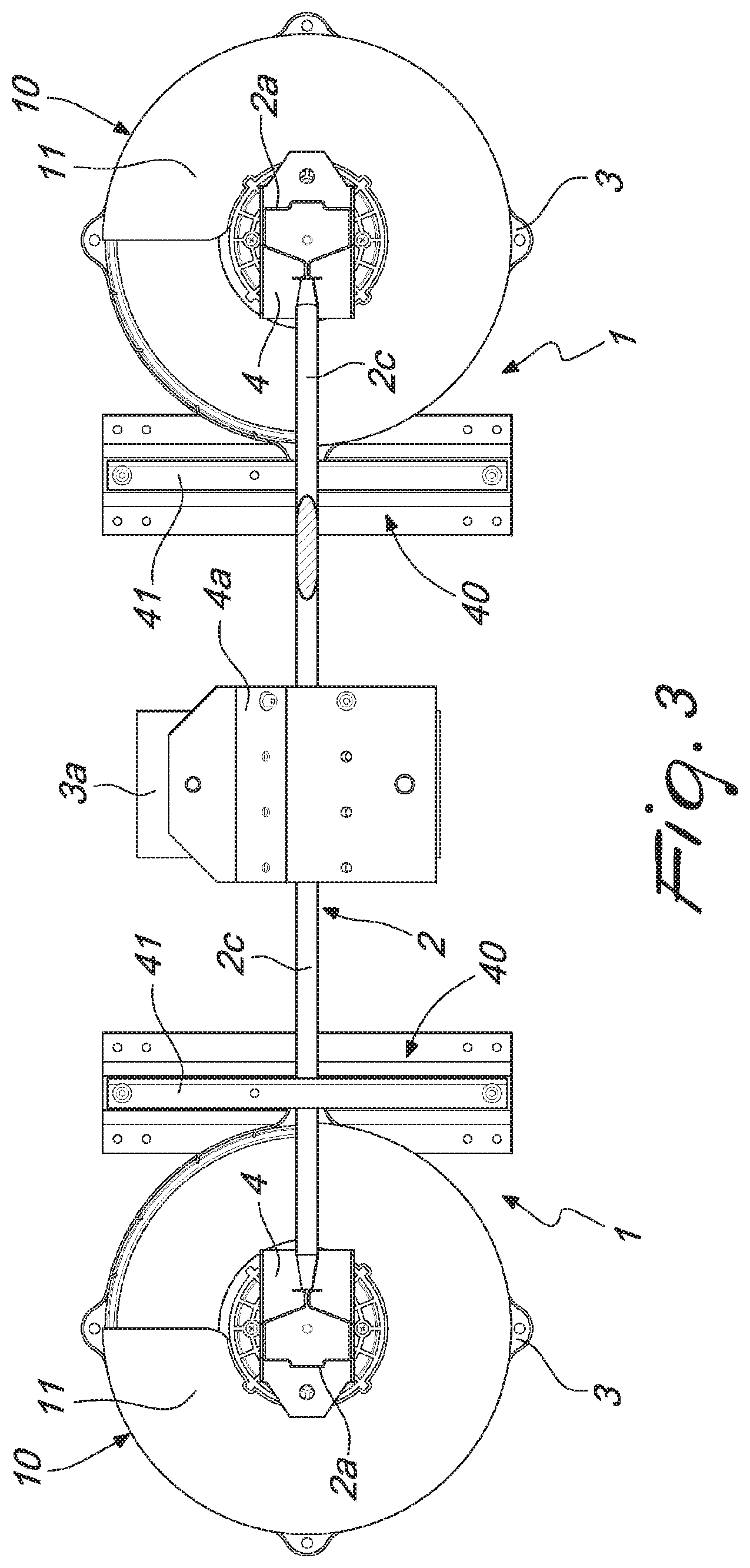
FIGS. 3 and 4 show a cross-section of the shelving unit taken along the lines marked III-III and IV-IV in FIG. 2, in which the dissipator is, respectively, in the "at rest" condition and in the "in operation" condition;
FIG. 5 is a cross-sectional view taken along a vertical plane of a shelving unit and of the dissipator according to the invention;
FIGS. 6 and 7 show, respectively, a cross-sectional view of the shelving unit taken along the vertical plane passing through the rod-like dissipation body, in which the dissipator is, respectively, in the "at rest" condition and in the "in operation" condition.
In the embodiments illustrated, individual characteristics shown in relation to specific examples may in reality be interchanged with other, different characteristics, existing in other embodiments.
The present invention relates to a dissipator, generally designated with the reference numeral 1, for interfacing between the ground 100 and supporting structures 2.
The dissipator 1 comprises at least one supporting base 3, which can be fixed to the ground 100 and supports a contact base 4.
The supporting base 3 is typically constituted by a plate element, which is intended to be fixed to the ground 100 by way of conventional fixing means, such as for example mechanical anchoring means (such as for example inserts) and/or chemical anchoring means (such as for example threaded bars with resins).
The contact base 4, which is advantageously arranged above the supporting base 3, can be associated, by way of kinematic connection means that are conventional, with a supporting structure 2.
In particular, the kinematic connection means stably associate the contact base 4 with a lower portion of a respective upright member 2a of a supporting structure 2, such as for example an industrial shelving unit.
More specifically, between the contact base 4 and the supporting base 3 interface means 10 are provided, which are adapted to allow the movement of the contact base 4 with respect to the supporting base 3 at least along two directions that are parallel to the ground 100.
Advantageously, the interface means 10 are adapted to allow the contact base 4 to move in all directions in the plane that is substantially parallel to the ground 100.
The dissipator 1 has, further, control means 11 which act between the supporting base 3 and the contact base 4, which are adapted to control the relative movement between the supporting base 3 and the contact base 4.
According to the present invention, the dissipator 1 comprises at least one rod-like dissipation body 20 that acts between the ground 100 and the supporting structure 2.
In particular, the rod-like dissipation body 20 has at least partially a behavior of the dissipative type.
Specifically, the rod-like dissipation body or bodies 20 makes or make it possible to dissipate the energy generated by an event, typically by an earthquake, by allowing the movement, on a plane that is parallel to the ground 100, of the supporting structures with respect to the supporting base 3.
The rod-like dissipation body 20 further makes it possible to reduce the demand in terms of movement, and the consequent optimization of the encumbrances and full control of the movements of the supporting structure during the seismic event, aspects that are particularly important for supporting structures 2 such as industrial shelving.
Advantageously, it is possible for a supporting structure 2 to be associated with a plurality of rod-like dissipation bodies 20.
In particular, respective rod-like dissipation bodies 20 can be arranged at each shoulder of the supporting structure 2.
Conveniently, the dissipator 1 has at least one device of the fuse-equipped type 30 connecting the ground 100 and the supporting structure 2.
In particular, the device of the fuse-equipped type 30 is adapted to prevent the relative movements between the contact base 4 and the supporting base 3 along the at least two directions that are parallel to the ground 100 below a preset stress threshold value that acts between the supporting base 3 and the contact base 4 on a plane that is parallel to the ground 100.
Preferably, the device of the fuse-equipped type 30 connects the contact base 4 and the respective supporting base 3.
Advantageously, the rod-like dissipation body 20 is arranged between the supporting base 3 and the respective contact base 4.
Preferably, the dissipator 1 comprises at least one base body 3a that can be fixed to the ground 100 and at least one abutment body 4a that can be fixed to the supporting structure 2.
Obviously, there is no reason why the rod-like dissipation body 20 cannot be arranged between the ground 100 and a portion of the supporting structure 2.
For the purposes of example, the rod-like dissipation body 20 can be resin-bonded in a hole made in the ground and interfaced with an abutment that is defined for example at a stringer 2b or the shoulder strut structure 2c of the supporting structure 2.
Advantageously, the device of the fuse-equipped type 30 and/or the rod-like dissipation body 20 is/are arranged between the base body 3a and the respective abutment body 4a.
With reference to the embodiment shown in FIGS. 1 to 4, it is possible for the base body 3a to be fixed to the ground 100 in a position spaced apart from the supporting base 3.
In this case, the abutment body 4a is preferably fixed to a stringer 2b or to the shoulder strut structure 2c of the supporting structure 2.
It is likewise possible, as shown in FIGS. 5 to 7, for the base body 3a to be fixed directly to the supporting base 3 and the abutment body 4a to be in turn fixed to the upright member 2a or to the contact base 4.
Preferably, the dissipator 1 comprises a tipping prevention device 40, which is adapted to prevent the movement of the supporting structure 2 along a direction that is perpendicular to a plane that is substantially parallel to the ground 100.
With reference to the embodiments shown in the figures, the tipping prevention device 40 can be constituted by one or more immobilizing cross-members 41, in use parallel to the ground 100, which can be fixed to at least one abutment shoulder 42 that is erected on a supporting base thereof and is arranged above an abutment element, which is for example constituted by a stringer 2b or by the strut structure 2c.
According to a preferred embodiment, the control means 11 comprise means of control of the movement of the contact base 4 with respect to the supporting base 3.
In particular, the interface means 10, which comprise the control means 11, have substantially a behavior of the elastic type, or a behavior of the viscoelastic type, or a behavior of the viscoelastoplastic type.
For the purposes of example, the control means 11 mutually connect the supporting base 3 and the contact base 4 and can be constituted by a slab of rubber or by a plurality of radially extending connection elements arranged in a radiating pattern such as, for example, springs.
The interface means 10 can comprise a plurality of balls that rest on the supporting base 3 and support the contact base 4 or a slab with a low friction coefficient made, for example, of PTFE or polyzene.
Preferably, the rod-like dissipation body 20 extends along a main direction, which is arranged substantially at right angles to the ground 100.
Advantageously, the rod-like dissipation body 20 comprises a resisting portion 22 and a dissipative portion 21.
In particular, the resisting portion 22 is connected to the supporting structure 2 while the dissipative portion 21 is connected to the ground 100.
Obviously, there is no reason why the resisting portion 22 cannot be connected to the ground 100 and the dissipative portion 21 cannot be connected to the supporting structure 2.
The rod-like dissipation body 20 can be made of a material selected from the group comprising: lead; lead alloy; aluminum; aluminum alloy; iron; steel; stainless steel; elastomer; polymeric material; composite metallic material; composite polymeric material;
or combinations thereof.
Conveniently, the rod-like dissipation body 20 is substantially cylindrical so as to have an isotropic behavior.
Advantageously the rod-like dissipation body 20 has a cylindrical cross-section that is non-constant along its height so as to increase the dissipative effect.
Preferably, the rod-like dissipation body 20 is interfaced with the supporting structure 2 by way of a plate with a slot, which is adapted to allow the sliding of the end of the rod-like dissipation body 20 during the seismic event within the slot.
Conveniently, the slot is associated with a gasket and/or with an element with a low friction coefficient and/or with a ball joint.
Advantageously, the slot defines a stroke limit for the end of the rod-like dissipation body 20.
Conveniently, at one end or at both ends of the rod-like dissipator 20 there is or there are stop retainers, with or without a damping element or elements.
Advantageously, the slot/rod-like dissipator 20 coupling is provided so as to generate a further energy dissipation.
In this regard there can be, between the rod-like dissipator 20 and the respective abutment body 4a, at least one interposition element that is adapted to allow a further energy dissipation.
Conveniently, the transverse cross-section of the resisting portion 22 of the rod-like dissipation body 20 is circular and as small as possible compatibly with the material and with the geometry used and with the required damping characteristics: this makes it possible to reduce the play between the slot and the resisting portion 22 to the minimum.
There is no reason why the rod-like dissipation body 20 cannot be provided in a single piece.
The dissipative portion 21, which is made of metallic material, advantageously dissipates energy by elastoplastic bending.
Conveniently the dissipative portion 21 of the rod-like dissipation body 20 can be made of lead, lead alloy, aluminum, aluminum alloy, steel, stainless steel, other metallic materials, polymeric materials, rubber and composite materials or a combination thereof.
Advantageously, the resisting portion 22 of the rod-like dissipation body 20 can be constituted of other metallic materials, polymeric materials, or rubber and composite materials.
According to a possible variation of embodiment, the dissipative portion 21 of the rod-like dissipation body 20 can be connected to another portion, which is also dissipative, in lieu of the resisting portion, by way of, for example, an elastic or viscoelastic or viscoelastoplastic element.
Alternatively, the resisting portion 22 and the dissipative portion 21 of the rod-like dissipation body 20 can be made with different materials and geometric sections than those indicated above.
The device of the fuse-equipped type 30 can be provided in one piece and from a single material, metallic, polymeric or composite.
Advantageously the device of the fuse-equipped type 30 comprises a resisting part 30a made of a first material, for example metal, and a part intended to break 30b made of a second material, for example polymeric material (preferably ABS), metallic material or stone-like material.
Conveniently, the part of the device of the fuse-equipped type that is intended to break 30b has a different performance along a direction that is parallel to the transverse direction (cross aisle direction) and along a direction that is parallel to the longitudinal direction (down aisle direction) of the supporting structure 2.
Advantageously, the part intended to break 30b has a higher resistance in the cross aisle direction in order to ensure a suitable resistance during the storage operations on the supporting structures 2.
According to a preferred embodiment, the device of the fuse-equipped type 30 has the part intended to break 30b interfaced with the ground 100 and/or with the supporting structure 2 by way of interposition of a slotted element.
Preferably, such slotted element comprises a gasket.
Advantageously, the slotted element is defined on the base body 3a, or on the abutment body 4a, or on the stringer 2b and/or on the shoulder strut structure 2c of the supporting structure 2.
The resisting part 30a and the part intended to break in a controlled manner 30b can be made of metallic, polymeric or composite material.
Conveniently, in order to limit the effects owing to impulsive actions as a result of warehousing activities (picking), the part that breaks in a controlled manner 30b of the fuse pin is engaged in a hole provided with a gasket.
Alternatively, the resisting part 30a and the part intended to break in a controlled manner 30b can be made with different materials and geometric sections than those indicated above.
The device of the fuse-equipped type 30 and the tipping prevention device 40 act as immobilization means (for a preset force value) under non-seismic conditions: this ensures stability of the industrial shelving unit and correct operating modes and safety conditions during warehousing activities (picking).
The intrinsic behavior of the rod-like dissipation body 20 makes it possible to obtain, as a result of a seismic event, a significant reduction in the amplification of the movements of the supporting structure 2 on a plane that is substantially parallel to the ground 100.
In particular, its characteristic hysteretic dissipative behavior causes a continuous energy dissipation during seismic activity.
Operation of the dissipator 1 according to the present invention is evident from the foregoing description.
In particular, if the ground 100 on which the supporting structure 2 is fixed is subjected to a dynamic action (for example a seismic action), the movements of the ground 100, and thus of the supporting base 3, result in the breakage of the device of the fuse-equipped type 30, if fitted, and "activate" the interface means 10 that is entrusted with the task of isolating the supporting structure 2 from the ground 100.
During the relative movement between the contact base 4 and the supporting structure 3, the rod-like dissipation body 20 absorbs part of the energy, thus limiting the relative movements between the contact base 4 and the supporting base 3.
All the characteristics of the invention, indicated above as advantageous, convenient or similar, may also be missing or be substituted by equivalent characteristics.
The invention, thus conceived, is susceptible of numerous modifications and variations, all of which are within the scope of the appended claims.
It has further been found that a dissipator according to the present invention can also be used in different fields of application, such as, for example, in the seismic protection of systems and components for the construction industry, buildings, artworks, cultural assets and other structures.
In practice the materials employed, provided they are compatible with the specific use, and the dimensions and shapes, may be any according to requirements.
Moreover, all the details may be substituted by other, technically equivalent elements.
The disclosures in Italian Patent Application No. VR2014A000015 from which this application claims priority are incorporated herein by reference.
* * * * *
D00000
D00001
D00002
D00003
D00004
D00005
D00006
D00007
XML
uspto.report is an independent third-party trademark research tool that is not affiliated, endorsed, or sponsored by the United States Patent and Trademark Office (USPTO) or any other governmental organization. The information provided by uspto.report is based on publicly available data at the time of writing and is intended for informational purposes only.
While we strive to provide accurate and up-to-date information, we do not guarantee the accuracy, completeness, reliability, or suitability of the information displayed on this site. The use of this site is at your own risk. Any reliance you place on such information is therefore strictly at your own risk.
All official trademark data, including owner information, should be verified by visiting the official USPTO website at www.uspto.gov. This site is not intended to replace professional legal advice and should not be used as a substitute for consulting with a legal professional who is knowledgeable about trademark law.