Flexible feeding and closing machine for hinged caps
Nicholson , et al.
U.S. patent number 10,589,973 [Application Number 15/031,856] was granted by the patent office on 2020-03-17 for flexible feeding and closing machine for hinged caps. This patent grant is currently assigned to ATS Automation Tooling Systems Inc.. The grantee listed for this patent is ATS Automation Tooling Systems Inc.. Invention is credited to Robert David Almas, Philip David Munroe, Kenneth Wayne Nicholson, Martin George Smith.
| United States Patent | 10,589,973 |
| Nicholson , et al. | March 17, 2020 |
Flexible feeding and closing machine for hinged caps
Abstract
An automated device for producing a closed part, commencing with an open part having a cap joined with a hinge to a body, the device comprising: a tool having a guide surface defined in an operating plane substantially orthogonal to a hinge axis; a part gripper disposed on a computer numerically controlled shuttle, the part gripper operable to: select an open part from a stream of identical open parts; engage one of: the cap; and the body, on a start point on the guide surface; slide the open part, within the operating plane from the start point to a finish point on the guide surface, to rotate the cap about the hinge axis from an open position to a closed position relative to the body; and release the closed part from the part gripper at a release station.
| Inventors: | Nicholson; Kenneth Wayne (Kingston, CA), Munroe; Philip David (Kingston, CA), Smith; Martin George (Kingston, CA), Almas; Robert David (Kingston, CA) | ||||||||||
|---|---|---|---|---|---|---|---|---|---|---|---|
| Applicant: |
|
||||||||||
| Assignee: | ATS Automation Tooling Systems
Inc. (Cambridge, CA) |
||||||||||
| Family ID: | 52992072 | ||||||||||
| Appl. No.: | 15/031,856 | ||||||||||
| Filed: | October 9, 2014 | ||||||||||
| PCT Filed: | October 09, 2014 | ||||||||||
| PCT No.: | PCT/CA2014/000737 | ||||||||||
| 371(c)(1),(2),(4) Date: | April 25, 2016 | ||||||||||
| PCT Pub. No.: | WO2015/058277 | ||||||||||
| PCT Pub. Date: | April 30, 2015 |
Prior Publication Data
| Document Identifier | Publication Date | |
|---|---|---|
| US 20160264388 A1 | Sep 15, 2016 | |
Related U.S. Patent Documents
| Application Number | Filing Date | Patent Number | Issue Date | ||
|---|---|---|---|---|---|
| 61895534 | Oct 25, 2013 | ||||
| Current U.S. Class: | 1/1 |
| Current CPC Class: | B25J 9/0093 (20130101); B67B 3/20 (20130101); B25J 9/0051 (20130101); B29C 45/42 (20130101); B29C 45/006 (20130101) |
| Current International Class: | B67B 3/20 (20060101); B25J 9/00 (20060101) |
| Field of Search: | ;53/285 ;29/527.1 |
References Cited [Referenced By]
U.S. Patent Documents
| 3886421 | May 1975 | Hassan et al. |
| 3904945 | September 1975 | Hassan et al. |
| 4040595 | August 1977 | Tecco |
| 4238023 | December 1980 | Millar et al. |
| 4340352 | July 1982 | Hayberg |
| 4522581 | June 1985 | Schad et al. |
| 4604704 | August 1986 | Eaves et al. |
| 4620347 | November 1986 | Stark et al. |
| 4690633 | September 1987 | Schad et al. |
| 4782274 | November 1988 | Teegarden et al. |
| 4847988 | July 1989 | Eitzinger |
| 5136222 | August 1992 | Yamamoto et al. |
| 5473975 | December 1995 | Bruno et al. |
| 5934496 | August 1999 | Mogard |
| 6401011 | June 2002 | Hashimukai |
| 6404160 | June 2002 | Sagasaki et al. |
| 6625866 | September 2003 | Stone et al. |
| 6856854 | February 2005 | Endo et al. |
| 6885909 | April 2005 | Isohata |
| 6917837 | July 2005 | Hashimoto et al. |
| 7030585 | April 2006 | Iwashita et al. |
| 7089085 | August 2006 | Kim |
| 7180253 | February 2007 | Weinhofer et al. |
| 7183739 | February 2007 | Iwashita et al. |
| 7272524 | September 2007 | Brogaardh |
| 7298385 | November 2007 | Kazi et al. |
| 7385370 | June 2008 | Sekiguchi |
| 7463002 | December 2008 | Tanaka |
| 7525274 | April 2009 | Kazi et al. |
| 7529599 | May 2009 | Bhatt et al. |
| 7650984 | January 2010 | Giuliani et al. |
| 7729804 | June 2010 | Matsumoto et al. |
| 7729910 | June 2010 | Printz |
| 7740125 | June 2010 | Dermarderosian et al. |
| 7795833 | September 2010 | Sekiguchi |
| 8000818 | August 2011 | Bhatt et al. |
| 8005563 | August 2011 | Cobb et al. |
| 8417363 | April 2013 | Erlandsson-Warvelin et al. |
| 8977394 | March 2015 | Khoukhi et al. |
| 8996168 | March 2015 | Murray, IV et al. |
| 9776330 | October 2017 | Day et al. |
| 9802507 | October 2017 | Clark et al. |
| 9904281 | February 2018 | Nicholson et al. |
| 9943961 | April 2018 | Nakazato et al. |
| 10018985 | July 2018 | Nicholson et al. |
| 2004/0052891 | March 2004 | Kalemba |
| 2004/0262127 | December 2004 | Harnish et al. |
| 2005/0085359 | April 2005 | Stave et al. |
| 2006/0085085 | April 2006 | Duemler |
| 2007/0284216 | December 2007 | Meier et al. |
| 2012/0221140 | August 2012 | Berman et al. |
| 2015/0274436 | October 2015 | Di Donna |
| 2018/0118467 | May 2018 | Gregory |
| 2045600 | Feb 1996 | CA | |||
| 1275115 | Nov 2000 | CN | |||
| 1748286 | Mar 2006 | CN | |||
| 101578162 | Nov 2009 | CN | |||
| 60302920 | Jul 2006 | DE | |||
| 10314025 | Apr 2010 | DE | |||
| 0173818 | Mar 1986 | EP | |||
| 1353251 | Dec 2005 | EP | |||
| 1607194 | Oct 2008 | EP | |||
| 1221353 | Jan 2009 | EP | |||
| 1793292 | Nov 2009 | EP | |||
| 1455438 | Dec 2009 | EP | |||
| 1424613 | Apr 2010 | EP | |||
| 1705541 | Jul 2010 | EP | |||
| 1349027 | Nov 2010 | EP | |||
| 1349129 | Nov 2010 | EP | |||
| 1122036 | Jan 2011 | EP | |||
| 1462895 | Apr 2011 | EP | |||
| 1635995 | Jan 2012 | EP | |||
| 1942476 | Dec 2012 | EP | |||
| 2985113 | Mar 2018 | EP | |||
| 2187332 | Oct 2004 | ES | |||
| 1360441 | Jul 1974 | GB | |||
| 2225651 | Jun 1990 | GB | |||
| H042421 | Jan 1992 | JP | |||
| 82/02359 | Jul 1982 | WO | |||
| 2009053432 | Apr 2009 | WO | |||
| 2014078938 | May 2014 | WO | |||
| 2015058277 | Apr 2015 | WO | |||
| 2016023101 | Feb 2016 | WO | |||
Other References
|
EP Supplementary Search Report for EP 14 85 5374 dated Sep. 21, 2016. cited by applicant . Australian Patent Application No. AU2013350264, Examination Report dated Sep. 30, 2016. cited by applicant . Brazilian Patent Application No. BR112014004246.2, Office Action dated Jul. 3, 2017. cited by applicant . Brazilian Patent Application No. BR112014004257.8, Office Action dated Jun. 25, 2017. cited by applicant . Chinese Patent Application No. CN2013800611704, First Office Action dated Dec. 26, 2016--English Translation Available. cited by applicant . Chinese Patent Application No. CN2013800611704, Second Office Action dated Jul. 31, 2017--English Translation Available. cited by applicant . European Patent Application No. 13856718.5, Office Action dated Feb. 5, 2016. cited by applicant . European Patent Application No. 13856718.5, Supplementary European Search Report dated Dec. 21, 2015. cited by applicant . European Patent Application No. 15832329.5, Supplementary European Search Report dated Feb. 8, 2018. cited by applicant . International Patent Application No. PCT/CA2013/000974, International Preliminary Report on Patentability dated May 26, 2015. cited by applicant . International Patent Application No. PCT/CA2013/000974, International Search Report and Written Opinion dated Feb. 10, 2014. cited by applicant . International Patent Application No. PCT/CA2014/000737, International Preliminary Report on Patentability dated Apr. 26, 2016. cited by applicant . International Patent Application No. PCT/CA2014/000737, International Search Report and Written Opinion dated Dec. 30, 2014. cited by applicant . International Patent Application No. PCT/CA2015/000460, International Preliminary Report on Patentability dated Feb. 14, 2017. cited by applicant . International Patent Application No. PCT/CA2015/000460, International Search Report and Written Opinion dated Nov. 3, 2015. cited by applicant . Mexican Patent Application No. Mx/a/2015/006522, Office Action dated Feb. 13, 2017. cited by applicant . Singapore Application No. SG20151103884V, Supplementary Examination Report dated Sep. 4, 2015. cited by applicant . Sprovieri, J., Servos Revolutionize High-Speed Assembly, Jan. 8, 2014, Retrieved from the Internet: (https://www.assemblymag.com/articles/91810-servos-revolutionize-high-spe- ed-assembly), Copyright .COPYRGT.2019, All Rights Reserved BNP Media. cited by applicant . Sprovieri., "XYZ: Electronic Camming Improves Pick-and-Place," Assembly Magazine, Mar. 2012, http://www.assemblymag.com/articles/print/89833 2 pages. cited by applicant . U.S. Appl. No. 15/503,104, Notice of Allowance dated Feb. 23, 2018. cited by applicant . U.S. Appl. No. 15/503,104, Notice of Allowance dated Jun. 13, 2018. cited by applicant . U.S. Appl. No. 14/087,419, Final Office Action dated Sep. 26, 2017. cited by applicant . U.S. Appl. No. 14/087,419, Non-Final Office Action dated Apr. 14, 2017. cited by applicant . U.S. Appl. No. 14/087,419, Non-Final Office Action dated Oct. 28, 2016. cited by applicant . U.S. Appl. No. 14/087,419, Notice of Allowance dated Dec. 21, 2017. cited by applicant . U.S. Appl. No. 14/087,419, Notice of Allowance dated Oct. 12, 2017. cited by applicant . Using Electronic Cams for Motion Control; Machine Design/Technologies; Motion System Design, Langnau, Leslie, Jul. 2000; http://machinedesign.com. cited by applicant . U.S. Provisional Appl. No. 61/782,758 filed on Mar. 14, 2013. cited by applicant . U.S. Provisional Appl. No. 61/729,480 filed on Nov. 23, 2012. cited by applicant . U.S. Provisional Appl. No. 62/036,305 filed on Aug. 12, 2014. cited by applicant . U.S. Appl. No. 15/903,244 filed on Feb. 23, 2018. cited by applicant . U.S. Provisional Appl. No. 62/746,823 filed on Oct. 24, 2018. cited by applicant . Japanese Patent Application No. 2017-527954, Office Action dated Aug. 21, 2019--English Translation available. cited by applicant . International Patent Application No. PCT/CA2019/051470, International Search Report and Written Opinion dated Dec. 12, 2019. cited by applicant . Brazilian Patent Application No. BR112015011856-9, Office Action dated Jan. 14, 2020. cited by applicant. |
Primary Examiner: Long; Robert F
Assistant Examiner: Madison; Xavier A
Attorney, Agent or Firm: Borden Ladner Gervais LLP
Claims
We claim:
1. An automated device for producing a closed part, commencing with an open part having a cap joined with a hinge to a body, the device comprising: a tool having a guide surface defined in an operating plane substantially orthogonal to a hinge axis; a part gripper disposed on a computer numerically controlled shuttle, the part gripper operable to: select an open part from a stream of identical open parts; engage one of: the cap; and the body, on a start point on the guide surface; slide the open part, within the operating plane from the start point to a finish point on the guide surface, to rotate the cap about the hinge axis from an open position to a closed position relative to the body; and release the closed part from the part gripper at a release station; wherein the computer numerically controlled shuttle comprises at least two linear motion actuators disposed orthogonally and each having a linear operating path parallel to the operating plane; and wherein the at least two linear motion actuators are independently programmable to drive the part gripper along a selected path within the operating plane.
2. The automated device according to claim 1, wherein the tool comprises a roller mounted for rotation about a roller axis parallel to the hinge axis and having a circumferential guide surface.
3. The automated device according to claim 2, wherein the roller comprises a freely rotating idler roller.
4. The automated device according to claim 1, comprising: a feed conveyor on which the stream of open parts is disposed in a selected orientation.
5. The automated device according to claim 4, comprising: a feed manipulator having an end effector for picking open parts from a first portion of the feed conveyor and placing open parts spaced apart into said stream of open parts on a second portion of the feed conveyor in the selected orientation.
6. The automated device according to claim 5, wherein the feed manipulator comprises an overhead parallel motion robot with optical scanning capability.
7. The automated device according to claim 5, comprising: a loading hopper having an intake opening for receiving randomly oriented open parts and an outlet opening for loading open parts on the second portion of the feed conveyor.
8. The automated device according to claim 7, wherein the outlet opening of the loading hopper includes a dispensing blade disposed a selected distance from the second portion of the feed conveyor, the selected distance being greater than a height and less than a width of the open parts.
9. The automated device according to claim 7, wherein an end portion of the feed conveyor is disposed above a return conveyor to recirculate open parts back to the loading hopper.
10. The automated device according to claim 1, wherein the release station includes an optical scanner in communication with a deflector for directing towards a completed part conveyor and a reject part conveyor.
11. An automated device for producing a closed part, commencing with an open part having a cap joined with a hinge to a body, the device comprising: a tool having a guide surface defined in an operating plane substantially orthogonal to a hinge axis; a part gripper disposed on a computer numerically controlled shuttle, the part gripper operable to: select an open part from a stream of identical open parts; engage one of: the cap; and the body, on a start point on the guide surface; slide the open part, within the operating plane from the start point to a finish point on the guide surface, to rotate the cap about the hinge axis from an open position to a closed position relative to the body; and release the closed part from the part gripper at a release station; a feed conveyor on which the stream of open parts is disposed in a selected orientation; a feed manipulator having an end effector for picking open parts from a first portion of the feed conveyor and placing open parts spaced apart into said stream of open parts on a second portion of the feed conveyor in the selected orientation; and a loading hopper having an intake opening for receiving randomly oriented open parts and an outlet opening for loading open parts on the second portion of the feed conveyor; wherein the outlet opening of the loading hopper includes a dispensing blade disposed a selected distance from the second portion of the feed conveyor, the selected distance being greater than a height and less than a width of the open parts.
12. The automated device according to claim 11, wherein the tool comprises a roller mounted for rotation about a roller axis parallel to the hinge axis and having a circumferential guide surface.
13. The automated device according to claim 12, wherein the roller comprises a freely rotating idler roller.
14. The automated device according to claim 11, wherein the feed manipulator comprises an overhead parallel motion robot with optical scanning capability.
15. The automated device according to claim 11, wherein the release station includes an optical scanner in communication with a deflector for directing towards a completed part conveyor and a reject part conveyor.
16. An automated device for producing a closed part, commencing with an open part having a cap joined with a hinge to a body, the device comprising: a tool having a guide surface defined in an operating plane substantially orthogonal to a hinge axis; a part gripper disposed on a computer numerically controlled shuttle, the part gripper operable to: select an open part from a stream of identical open parts; engage one of: the cap; and the body, on a start point on the guide surface; slide the open part, within the operating plane from the start point to a finish point on the guide surface, to rotate the cap about the hinge axis from an open position to a closed position relative to the body; and release the closed part from the part gripper at a release station; a feed conveyor on which the stream of open parts is disposed in a selected orientation; a feed manipulator having an end effector for picking open parts from a first portion of the feed conveyor and placing open parts spaced apart into said stream of open parts on a second portion of the feed conveyor in the selected orientation; and a loading hopper having an intake opening for receiving randomly oriented open parts and an outlet opening for loading open parts on the second portion of the feed conveyor; wherein an end portion of the feed conveyor is disposed above a return conveyor to recirculate open parts back to the loading hopper.
17. The automated device according to claim 16, wherein the tool comprises a roller mounted for rotation about a roller axis parallel to the hinge axis and having a circumferential guide surface.
18. The automated device according to claim 17, wherein the roller comprises a freely rotating idler roller.
19. The automated device according to claim 16, wherein the feed manipulator comprises an overhead parallel motion robot with optical scanning capability.
20. The automated device according to claim 16, wherein the release station includes an optical scanner in communication with a deflector for directing towards a completed part conveyor and a reject part conveyor.
Description
TECHNICAL FIELD
The invention relates to an automated machine for closing hinged caps of closures for bottle and containers.
BACKGROUND OF THE ART
The manufacture of closures for containers generally involves thermoplastic injection molding of the sealing cap hinged together with the annular bottle mouth or container closure body in a single open part.
When plastic bottles or containers are filled, the contents are usually sealed with a tamper evident film over the open end and a closure is attached to threads or a snap locking ridge on the bottle neck over the opening. The closure must first be closed before being feed to the filling and capping machine where the closure is attached to the bottle or container by turning or press fitting.
Injection molded plastic closures with hinged caps and closure bodies are shown in U.S. Pat. Nos. 7,322,493 and 7,731,042, for example, an need not be explained in detail herein.
In some instances, the process of stripping the plastic closures from the injection mold can include rotation of the hinged cap to a closed position on the closure body, as shown for example by www.onemold.com at http://www.youtube.com/watch?v=QSgoXar3Xzc&feature=player_detailpage. For various reasons this method of closing the cap is not applicable. In some cases there is a need to cool the closure before closing the cap to avoid damage due to material or to achieve optimal mold cycle time. Further where closure bodies include nozzles or valves of different plastic materials that are installed in the closure opening in a separate step, the cap must be closed after the nozzle or valve is installed.
To close the hinged cap on the closure body specialized carousel machines are commonly used where random oriented closures are singulated in a stream of parts, then the open closures are placed from the stream into a socket in a rotating carousel, the cap is engaged with a cam or rail to rotate to a closed position, the partially closed part is transferred to another carousel with press closing tools, and compression is applied to snap the cap closed. For example see http://www.youtube.com/watch?feature=player_detailpage&v=yk GerA-zi0A.
However the conventional machinery for closing hinged caps is limited to a narrow range of sizes and shapes that can be efficiently handled. In general if a different sized closure or cap is required, the singulation, closing and compressing machinery must be modified to suit each closure. A different size or shape requires replacement of the machine parts that engage and hold the closure which involves significant expense and downtime. For this reason, closures of standard sizes and shapes are generally used to provide economies of scale in mass production. Colours can be modified by changing the plastic used for molding, however little other modification to the standard closure design is possible without extensive modification to the machinery that singulates, conveys and closes the cap on the closure body. Large quantities of identical closures are manufactured and used by packaging operators because the cost of changing the size and shape of closures is prohibitive. Smaller operators cannot compete due to the large capital costs involved. Closure designs are restricted to those standard shapes and sizes that can be manufactured and purchased at low cost.
It is desirable to provide flexibility in closure designs by allowing changes without requiring the handling, feeding and closing machinery to be extensively modified. Further it is desirable to allow packaging operators to adapt machinery rapidly so that smaller runs and custom closures can be accommodated without prohibitive costs.
Features that distinguish the present invention from the background art will be apparent from review of the disclosure, drawings and description of the invention presented below.
DISCLOSURE OF THE INVENTION
The invention provides an automated device for producing a closed part, commencing with an open part having a cap joined with a hinge to a body, the device comprising: a tool having a guide surface defined in an operating plane substantially orthogonal to a hinge axis; a part gripper disposed on a computer numerically controlled shuttle, the part gripper operable to: select an open part from a stream of identical open parts; engage one of: the cap; and the body, on a start point on the guide surface; slide the open part, within the operating plane from the start point to a finish point on the guide surface, to rotate the cap about the hinge axis from an open position to a closed position relative to the body; and release the closed part from the part gripper at a release station.
DESCRIPTION OF THE DRAWINGS
In order that the invention may be readily understood, one embodiment of the invention is illustrated by way of example in the accompanying drawings.
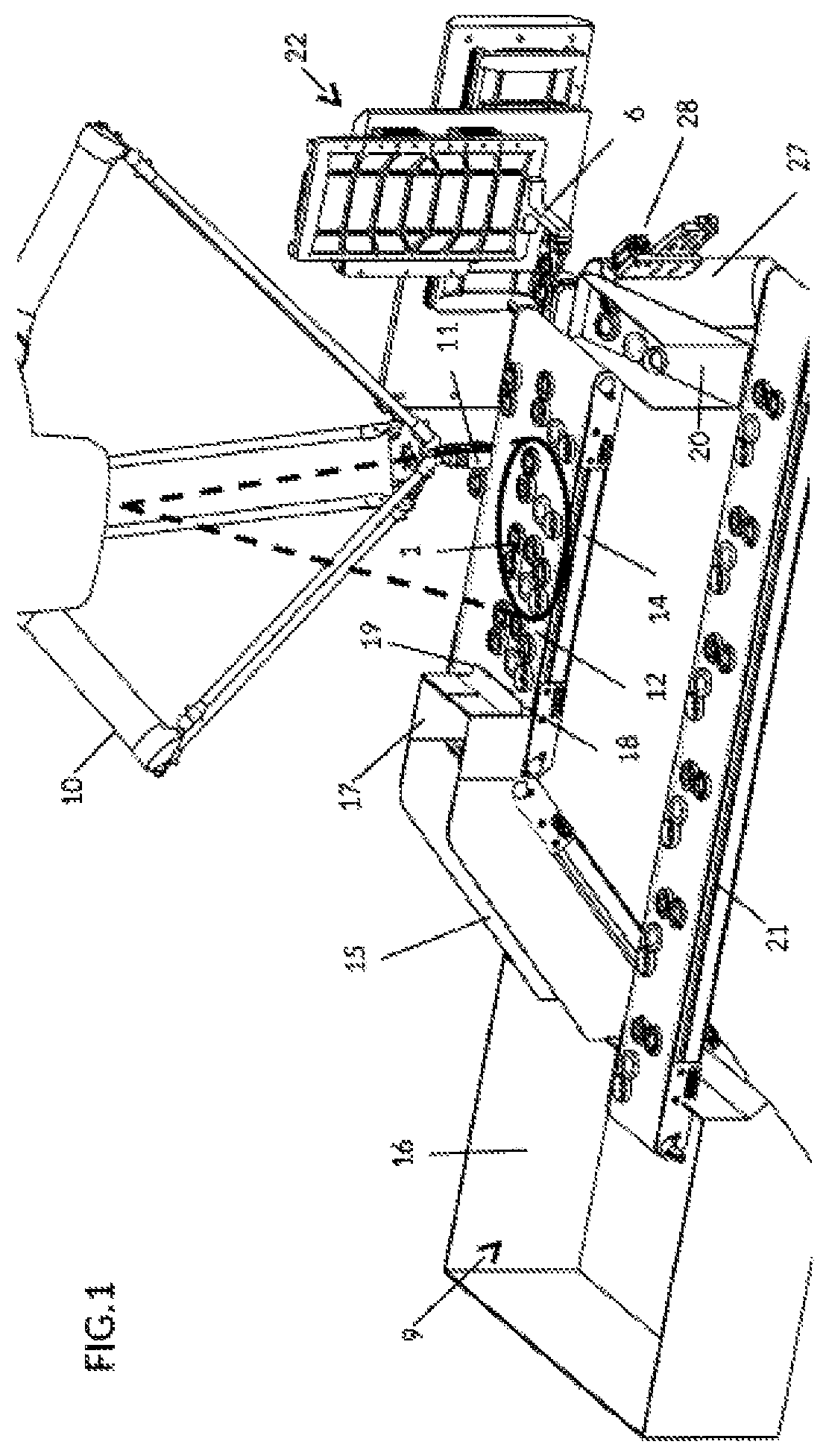
FIG. 1 is an isometric view of an automated device for receiving open parts, being bottle closures with a disc cap hinged to an annular body, and showing the overhead feed manipulator pick and place robot with optical scanner arranging open parts on the feed conveyor.
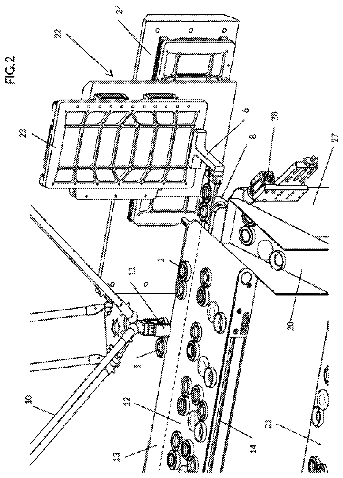
FIG. 2 is a detail view of a portion of FIG. 1 showing the feed conveyor that conveys oriented open parts toward the part gripper disposed on a two linear motion actuators that form an X-Z axis computer numerically controlled shuttle.
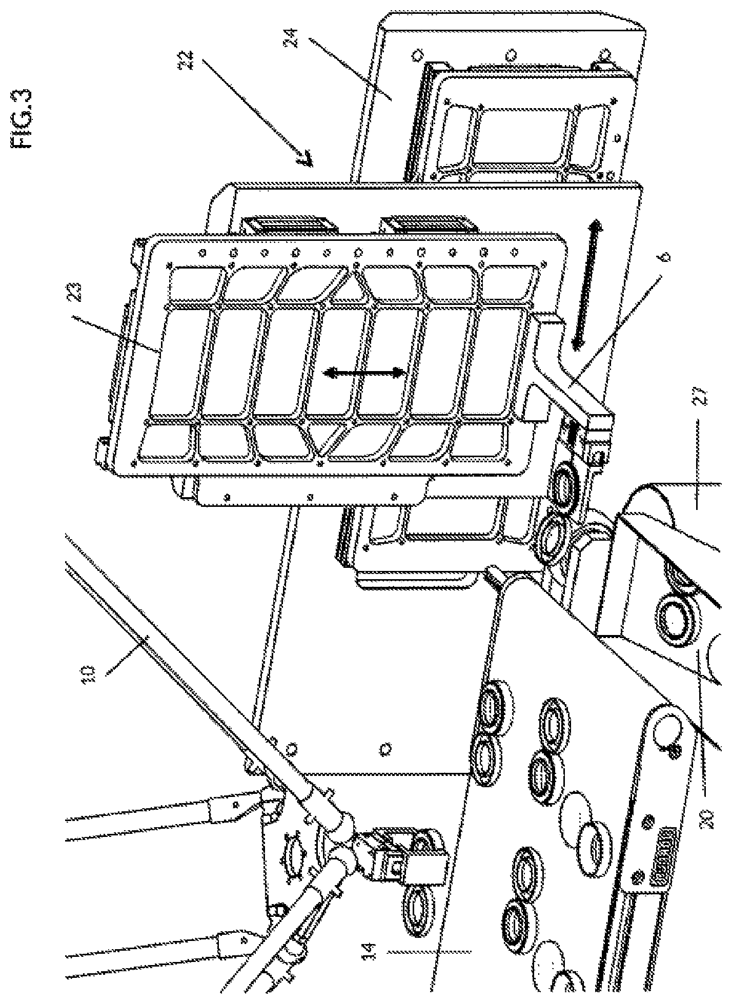
FIG. 3 is a detail view like FIG. 2 showing the initial contact of the hinged cap with the closing tool while the body is held in the part gripper and the shuttle moves the gripper around the closing tool.
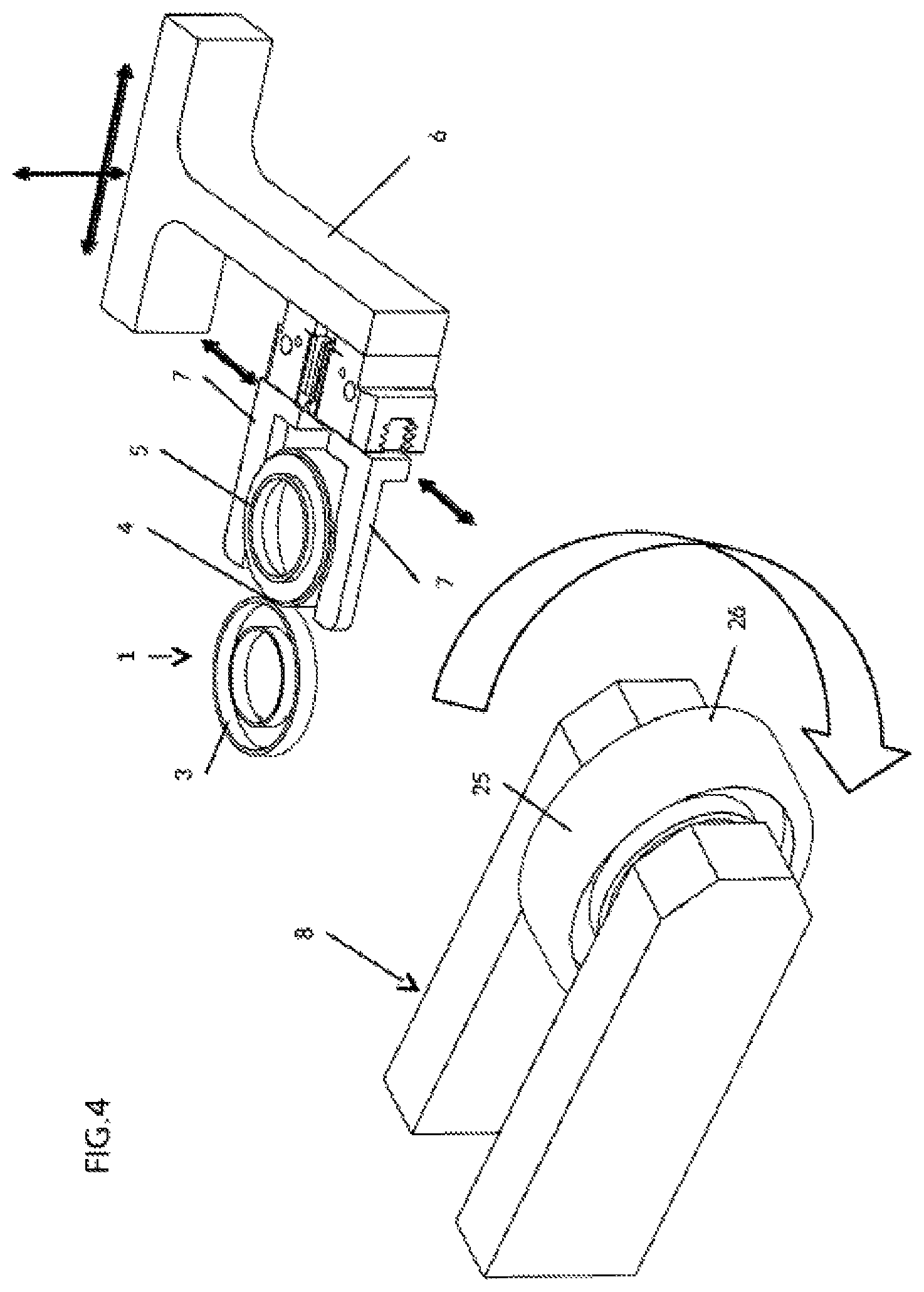
FIG. 4 is a detail view of the part gripper and the closing tool, being an idler roller that engages the hinged cap as the gripper is moved around the roller by the X-Z shuttle.
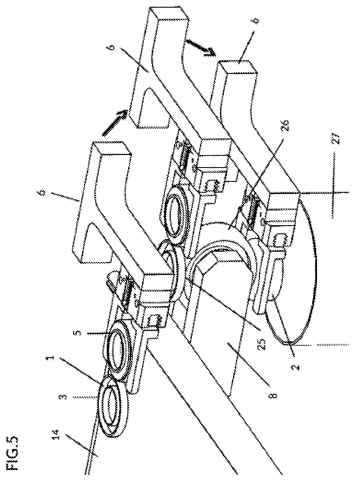
FIG. 5 is a detail view like FIG. 4 showing the movement of the part gripper around the roller tool where the upper position shows gripping of an open part from the feed conveyor, the middle position shows the engagement of the hinged cap with a top portion of the roller and the lower position shows the closing of the cap against the closure body.
Further details of the invention and its advantages will be apparent from the detailed description included below.
DETAILED DESCRIPTION OF PREFERRED EMBODIMENTS
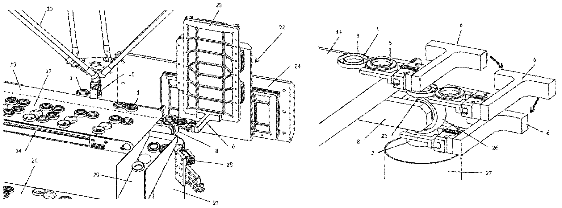
The purpose of the automated device is to take an open part 1 and produce a closed part 2 (see FIG. 5). The use of computer numerically controlled robots and actuators allows the automated device to be rapidly adapted to different sizes and shapes of closures, mainly through computer programing parameter selections and modifying the mechanical part grippers on the ends of the robots if necessary.
In the example illustrated, a conventional bottle end closure is the open part 1 shown in FIG. 4, having a cap 3 joined with a hinge 4 to an annular body 5. The part gripper 6 includes horizontally actuated fingers 7 to hold the body 5 but equally could be adapted to hold the cap 3 in an orientation rotated 180.degree.. As noted above, to accommodate different sized or shaped open parts 1, the fingers 7 can be easily removed and replaced if necessary. However in many cases the open parts 1 are circular and a variation in size can be accomplished by simply changing the spacing between the fingers 7. As indicated with arrows, the fingers 7 open and close, and the part gripper 6 is moved up-down and left-right with linear actuators to follow around the tool 8. As shown in FIG. 5, the movement of the part gripper 6 around the tool 8 results in closing of the hinged cap 3 to the body 4, which will be described in more detail below.
With reference to FIG. 1, the feeding of open parts 1 to the part gripper 6 is illustrated to supply the automated device and produce a closed part 2. The feeding sequence commences with identical open parts 1 deposited in random bulk orientation into the loading hopper 9 through an intake opening 16 for receiving randomly oriented open parts 1. A feed manipulator 10 is illustrated as an overhead parallel motion robot with optical scanning capability shown with conical dashed lines, also sometimes known as a pick-and-place robot. The feed manipulator 10 has an end effector 11 with gripping fingers and a rotary mount for picking and rotating the open parts 1. The feed manipulator 10 is programmed to automatically scan the open parts 1 on the feed conveyor 14 and then select open parts that are closest to the required position and orientation for placement in the stream which is fed toward the part gripper 6.
As better seen in FIG. 2 with a dashed line, the feed manipulator 10 picks open parts 1 from a first portion 12 of the feed conveyor 14 and places open parts 1 spaced apart into a conveyed stream of open parts 1 on a second portion 13 of the feed conveyor 14 in the selected orientation, namely with the annular body 5 towards the part gripper 6 in the example illustrated.
As seen in FIG. 1, the loading hopper 9 includes an inclined conveyor 15 and a pre-sorting hopper 17. The pre-sorting hopper 17 has an outlet opening 18 at it's bottom for dropping open parts 1 onto the first portion 12 of the feed conveyor 14 in an open flat position. The open parts 1 at this point may be right side up, up side down and in any angular orientation relative to the feed direction of the feed conveyor 14. The outlet opening 18 of the pre-sorting hopper 17 hopper includes a dispensing blade 19 disposed a selected distance from the first portion 12 of the feed conveyor 14. The selected distance is greater than the height and less than the width of the open parts 1, to arrange the open parts 1 laying flat on the feed conveyor 14. Any unintentionally closed parts will be retained in the pre-sorting hopper 17 to be periodically removed by an operator. Any open parts 1 that land on their sides in the pre-sorting hopper 17 will be jumbled around by the motion of the feed conveyor 14 until they are oriented flat and can pass through the outlet opening 18.
FIGS. 1 and 2 show the end of the first portion 12 of the feed conveyor 14 disposed above a return chute 20 of a return conveyor 21 to recirculate non-selected open parts 1 back to the loading hopper 9.
Recapping the closing method with reference to FIGS. 2 and 3, the part gripper 6 is disposed on a computer numerically controlled shuttle 22 having at least two linear motion actuators 23, 24 disposed orthogonally and each having a linear operating path parallel to the operating plane of the tool 8 and the part gripper 6. The two linear motion actuators 23, 24 are independently programmable to drive the part gripper 6 along a selected path within the operating plane
In the illustrated example, the vertical actuator 23 moves the part gripper 6 up and down, and the horizontal actuator 24 moves the part gripper 6 toward and away from the feed conveyor 14. Of course a third actuator (not shown) could also be included if necessary to move transverse to the feed conveyor direction to produce a three dimensional Cartesian coordinate robot. In the present example a two dimensional shuttle 22 is sufficient for the purpose. The part gripper 6 mounted on the shuttle 22 is operable to select an open part 1 from a stream of identical open parts 1 on the feed conveyor 14.
FIGS. 4 and 5 show a tool 8 that comprises a roller 26 mounted for rotation about a roller axis that is parallel to the hinge axis of the hinge 4. As is apparent in FIG. 5, the circumferential surface 25 of the roller 26 provides a low friction guide surface to engage the cap 3 during movement of the part gripper 6 in the operating plane which is defined substantially orthogonal to a hinge axis. The roller 26 as illustrated is a freely rotating idler roller but could also be driven or rotation may be controlled for various applications if required. The tool 8 can also be configured as a flat plate or a spherical resilient ball.
As seen in FIG. 5, the part gripper 6 removes the open part 1 from the feed conveyor 14 and moves toward the tool 8 to engage the cap 3 on an upper start point on the roller guide surface 25. As noted above, alternatively the cap 3 can be gripped and the body 5 can engage the roller guide surface 25. The part gripper 6 slides the open part 1 within the operating plane from the upper start point to a lower finish point on the guide surface 25. As a result the cap 3 rotates about the hinge axis from an open position to a closed position relative to the body 5.
The closed part 2 is then released from the part gripper at a release station above a completed part conveyor 27 for further assembly to a container. The release station can include an optical scanner 28 as seen in FIGS. 1 and 2 in communication with a deflector or air jet for directing towards the completed part conveyor 27 and a reject part conveyor.
Although the above description relates to a specific preferred embodiment as presently contemplated by the inventor, it will be understood that the invention in its broad aspect includes mechanical and functional equivalents of the elements described herein.
* * * * *
References
D00000
D00001
D00002
D00003
D00004
D00005
XML
uspto.report is an independent third-party trademark research tool that is not affiliated, endorsed, or sponsored by the United States Patent and Trademark Office (USPTO) or any other governmental organization. The information provided by uspto.report is based on publicly available data at the time of writing and is intended for informational purposes only.
While we strive to provide accurate and up-to-date information, we do not guarantee the accuracy, completeness, reliability, or suitability of the information displayed on this site. The use of this site is at your own risk. Any reliance you place on such information is therefore strictly at your own risk.
All official trademark data, including owner information, should be verified by visiting the official USPTO website at www.uspto.gov. This site is not intended to replace professional legal advice and should not be used as a substitute for consulting with a legal professional who is knowledgeable about trademark law.