Digital dental examination and documentation
Falkel
U.S. patent number 10,588,723 [Application Number 16/435,028] was granted by the patent office on 2020-03-17 for digital dental examination and documentation. This patent grant is currently assigned to uLab Systems, Inc.. The grantee listed for this patent is uLab Systems, Inc.. Invention is credited to Michael I. Falkel.


| United States Patent | 10,588,723 |
| Falkel | March 17, 2020 |
Digital dental examination and documentation
Abstract
Systems and methods are disclosed for processing and storing acquired data relating to one or more dental conditions. The methods can include acquiring a first oral feature in a first data acquisition using a data acquisition device, determining a first oral feature first reference point from the first data acquisition, diagnosing a first dental condition upon confirming that the first oral feature first reference point is associated with the first dental condition, acquiring the first oral feature in a second data acquisition using the data acquisition device, determining a first oral feature second reference point from the second data acquisition, and tracking the progression of the first dental condition by determining a discrepancy between the first oral feature first and second reference points.
| Inventors: | Falkel; Michael I. (Carmel, CA) | ||||||||||
|---|---|---|---|---|---|---|---|---|---|---|---|
| Applicant: |
|
||||||||||
| Assignee: | uLab Systems, Inc. (Redwood
City, CA) |
||||||||||
| Family ID: | 61617674 | ||||||||||
| Appl. No.: | 16/435,028 | ||||||||||
| Filed: | June 7, 2019 |
Prior Publication Data
| Document Identifier | Publication Date | |
|---|---|---|
| US 20190358002 A1 | Nov 28, 2019 | |
Related U.S. Patent Documents
| Application Number | Filing Date | Patent Number | Issue Date | ||
|---|---|---|---|---|---|
| 15710469 | Sep 20, 2017 | 10357342 | |||
| 62397525 | Sep 21, 2016 | ||||
| 62397504 | Sep 21, 2016 | ||||
| Current U.S. Class: | 1/1 |
| Current CPC Class: | A61C 9/0046 (20130101); A61B 5/0088 (20130101); G16H 30/40 (20180101); G16H 50/20 (20180101); G16H 10/60 (20180101); A61B 1/24 (20130101); A61B 6/14 (20130101); A61C 19/04 (20130101); G16H 30/20 (20180101); A61C 9/004 (20130101); A61B 6/032 (20130101); A61B 6/4085 (20130101); A61B 1/0005 (20130101); A61B 1/00009 (20130101) |
| Current International Class: | G16H 50/20 (20180101); A61B 1/24 (20060101); A61C 9/00 (20060101); G16H 10/60 (20180101); A61B 5/00 (20060101); G16H 30/40 (20180101); A61B 6/00 (20060101); A61B 6/03 (20060101); A61C 19/04 (20060101); A61B 1/00 (20060101); A61B 6/14 (20060101); G16H 30/20 (20180101) |
References Cited [Referenced By]
U.S. Patent Documents
| 4068379 | January 1978 | Miller et al. |
| 4889485 | December 1989 | Iida |
| 4983334 | January 1991 | Adell |
| 5055039 | October 1991 | Abbatte et al. |
| 5186623 | February 1993 | Breads et al. |
| 5691905 | November 1997 | Dehoff et al. |
| 5975893 | November 1999 | Chishti et al. |
| 6183248 | February 2001 | Chishti et al. |
| 6210162 | April 2001 | Chishti et al. |
| 6217325 | April 2001 | Chishti et al. |
| 6227850 | May 2001 | Chishti et al. |
| 6227851 | May 2001 | Chishti et al. |
| 6250918 | June 2001 | Sachdeva et al. |
| 6299440 | October 2001 | Phan et al. |
| 6309215 | October 2001 | Phan et al. |
| 6315553 | November 2001 | Sachdeva et al. |
| 6386878 | May 2002 | Pavlovskaia et al. |
| 6390812 | May 2002 | Chishti et al. |
| 6398548 | June 2002 | Muhammad et al. |
| 6454565 | September 2002 | Phan et al. |
| 6463344 | October 2002 | Pavloskaia |
| 6471511 | October 2002 | Chishti et al. |
| 6485298 | November 2002 | Chishti et al. |
| 6488499 | December 2002 | Miller |
| 6524101 | February 2003 | Phan et al. |
| 6554611 | April 2003 | Chishti et al. |
| 6572372 | June 2003 | Phan et al. |
| 6582227 | June 2003 | Phan et al. |
| 6602070 | August 2003 | Miller et al. |
| 6607382 | August 2003 | Kuo et al. |
| 6626666 | September 2003 | Chishti et al. |
| 6629840 | October 2003 | Chishti et al. |
| 6682346 | January 2004 | Chishti et al. |
| 6688885 | February 2004 | Sachdeva et al. |
| 6699037 | March 2004 | Chishti et al. |
| 6702575 | March 2004 | Hilliard |
| 6705861 | March 2004 | Chishti et al. |
| 6705863 | March 2004 | Phan et al. |
| 6722880 | April 2004 | Chishti et al. |
| 6729876 | May 2004 | Chishti et al. |
| 6761560 | July 2004 | Miller |
| 6783360 | August 2004 | Chishti |
| 6786721 | September 2004 | Chishti et al. |
| 6802713 | October 2004 | Chishti et al. |
| 6830450 | December 2004 | Knopp et al. |
| 6846179 | January 2005 | Chapouland et al. |
| 6857429 | February 2005 | Eubank |
| 6886566 | May 2005 | Eubank |
| 6964564 | November 2005 | Phan et al. |
| 7011517 | March 2006 | Nicozisis |
| 7029275 | April 2006 | Rubbert et al. |
| 7037108 | May 2006 | Chishti et al. |
| 7040896 | May 2006 | Pavlovskaia et al. |
| 7056115 | June 2006 | Phan et al. |
| 7059850 | June 2006 | Phan et al. |
| 7063533 | June 2006 | Phan et al. |
| 7074038 | July 2006 | Miller |
| 7077647 | July 2006 | Choi et al. |
| 7092784 | August 2006 | Simkins |
| 7104790 | September 2006 | Cronauer |
| 7121825 | October 2006 | Chishti et al. |
| 7125248 | October 2006 | Phan et al. |
| 7134874 | November 2006 | Chishti et al. |
| 7156661 | January 2007 | Choi et al. |
| 7160110 | January 2007 | Imgrund et al. |
| 7172417 | February 2007 | Sporbert et al. |
| 7192275 | March 2007 | Miller |
| 7220122 | May 2007 | Chishti |
| 7320592 | January 2008 | Chishti et al. |
| 7326051 | February 2008 | Miller |
| 7331783 | February 2008 | Chishti et al. |
| 7347688 | March 2008 | Kopelman et al. |
| 7416407 | August 2008 | Cronauer |
| 7434582 | October 2008 | Eubank |
| 7435083 | October 2008 | Chishti et al. |
| 7442041 | October 2008 | Imgrund et al. |
| 7458812 | December 2008 | Sporbert et al. |
| 7476100 | January 2009 | Kuo |
| 7553157 | June 2009 | Abolfathi et al. |
| 7559328 | July 2009 | Eubank |
| 7578673 | August 2009 | Wen et al. |
| 7590462 | September 2009 | Rubbert et al. |
| 7637262 | December 2009 | Bailey |
| 7641828 | January 2010 | Desimone et al. |
| 7658610 | February 2010 | Knopp |
| 7689398 | March 2010 | Cheng et al. |
| 7717708 | May 2010 | Sachdeva et al. |
| 7771195 | August 2010 | Knopp et al. |
| 7802987 | September 2010 | Phan et al. |
| 7824180 | November 2010 | Abolfathi et al. |
| 7826646 | November 2010 | Pavlovskaia et al. |
| 7841858 | November 2010 | Knopp et al. |
| 7854609 | December 2010 | Chen et al. |
| 7878801 | February 2011 | Abolfathi et al. |
| 7878804 | February 2011 | Korytov et al. |
| 7878805 | February 2011 | Moss et al. |
| 7883334 | February 2011 | Li et al. |
| 7901207 | March 2011 | Knopp et al. |
| 7905724 | March 2011 | Kuo et al. |
| 7914283 | March 2011 | Kuo |
| 7942672 | May 2011 | Kuo |
| 7943079 | May 2011 | Desimone et al. |
| 7957824 | June 2011 | Boronvinskih et al. |
| 7987099 | July 2011 | Kuo et al. |
| 8001972 | August 2011 | Eubank |
| 8021147 | September 2011 | Sporbert et al. |
| 8033282 | October 2011 | Eubank |
| 8038444 | October 2011 | Kitching et al. |
| 8070487 | December 2011 | Chishti et al. |
| 8075306 | December 2011 | Kitching et al. |
| 8099268 | January 2012 | Kitching et al. |
| 8099305 | January 2012 | Kuo et al. |
| 8105080 | January 2012 | Chishti et al. |
| 8123519 | February 2012 | Schultz |
| 8152518 | April 2012 | Kuo |
| 8152523 | April 2012 | Sporbert et al. |
| 8235713 | August 2012 | Phan et al. |
| 8272866 | September 2012 | Chun et al. |
| 8275180 | September 2012 | Kuo |
| 8292617 | October 2012 | Brandt et al. |
| 8303302 | November 2012 | Teasdale |
| 8348665 | January 2013 | Kuo |
| 8356993 | January 2013 | Marston |
| 8401686 | March 2013 | Moss et al. |
| 8401826 | March 2013 | Cheng et al. |
| 8439672 | May 2013 | Matov et al. |
| 8439673 | May 2013 | Korytov et al. |
| 8444412 | May 2013 | Baughman et al. |
| 8465280 | June 2013 | Sachdeva et al. |
| 8469705 | June 2013 | Sachdeva et al. |
| 8469706 | June 2013 | Kuo |
| 8496474 | July 2013 | Chishti et al. |
| 8512037 | August 2013 | Andreiko |
| 8517726 | August 2013 | Kakavand et al. |
| 8535580 | September 2013 | Puttler et al. |
| 8562337 | October 2013 | Kuo et al. |
| 8562338 | October 2013 | Kitching et al. |
| 8562340 | October 2013 | Chishti et al. |
| 8636509 | January 2014 | Miller |
| 8636510 | January 2014 | Kitching et al. |
| 8690568 | April 2014 | Chapoulaud et al. |
| 8708697 | April 2014 | Li et al. |
| 8734149 | May 2014 | Phan et al. |
| 8734150 | May 2014 | Chishti et al. |
| 8738165 | May 2014 | Cinader, Jr. et al. |
| 8765031 | July 2014 | Li et al. |
| 8777611 | July 2014 | Cios |
| 8780106 | July 2014 | Chishti et al. |
| 8807999 | August 2014 | Kuo et al. |
| 8858226 | October 2014 | Phan et al. |
| 8864493 | October 2014 | Leslie-Martin et al. |
| 8899976 | December 2014 | Chen et al. |
| 8899978 | December 2014 | Kitching et al. |
| 8930219 | January 2015 | Trosien et al. |
| 8936464 | January 2015 | Kopelman |
| 8944812 | February 2015 | Kuo |
| 8961173 | February 2015 | Miller |
| 8986003 | March 2015 | Valoir |
| 8992215 | March 2015 | Chapoulaud et al. |
| 8998608 | April 2015 | Trosien et al. |
| 9004915 | April 2015 | Moss et al. |
| 9022781 | May 2015 | Kuo et al. |
| 9026238 | May 2015 | Kraemer et al. |
| 9060829 | June 2015 | Sterental et al. |
| 9107722 | August 2015 | Matov et al. |
| 9119691 | September 2015 | Namiranian et al. |
| 9161823 | October 2015 | Morton et al. |
| 9161824 | October 2015 | Chishti et al. |
| 9204942 | December 2015 | Phan et al. |
| 9211166 | December 2015 | Kuo et al. |
| 9241774 | January 2016 | Li et al. |
| 9301814 | April 2016 | Kaza et al. |
| 9320575 | April 2016 | Chishti et al. |
| 9326830 | May 2016 | Kitching et al. |
| 9326831 | May 2016 | Cheang |
| 9333052 | May 2016 | Miller |
| 9345557 | May 2016 | Anderson et al. |
| 9351809 | May 2016 | Phan et al. |
| 9364297 | June 2016 | Kitching et al. |
| 9375300 | June 2016 | Matov et al. |
| 9414897 | August 2016 | Wu et al. |
| 9433476 | September 2016 | Khardekar et al. |
| 9492245 | November 2016 | Sherwood et al. |
| 9844420 | December 2017 | Cheang |
| 9922170 | March 2018 | Trosien et al. |
| 10022204 | July 2018 | Cheang |
| 10335250 | July 2019 | Wen |
| 10357336 | July 2019 | Wen |
| 10357342 | July 2019 | Falkel |
| 2001/0002310 | May 2001 | Chishti et al. |
| 2002/0010568 | January 2002 | Rubbert et al. |
| 2002/0025503 | February 2002 | Chapoulaud et al. |
| 2002/0042038 | April 2002 | Miller et al. |
| 2002/0072027 | June 2002 | Chisti |
| 2002/0094503 | July 2002 | Chishti et al. |
| 2002/0150859 | November 2002 | Imgrund et al. |
| 2002/0177108 | November 2002 | Pavlovskaia et al. |
| 2003/0008259 | January 2003 | Kuo et al. |
| 2003/0039940 | February 2003 | Miller |
| 2003/0190576 | October 2003 | Phan et al. |
| 2004/0023188 | February 2004 | Pavlovskaia et al. |
| 2004/0029068 | February 2004 | Sachdeva et al. |
| 2004/0038168 | February 2004 | Choi et al. |
| 2004/0142299 | July 2004 | Miller |
| 2004/0152036 | August 2004 | Abolfathi |
| 2004/0166456 | August 2004 | Chishti et al. |
| 2004/0166462 | August 2004 | Phan et al. |
| 2004/0166463 | August 2004 | Wen et al. |
| 2004/0197728 | October 2004 | Abolfathi et al. |
| 2004/0202983 | October 2004 | Tricca et al. |
| 2004/0242987 | December 2004 | Liew et al. |
| 2005/0010450 | January 2005 | Hultgren et al. |
| 2005/0019721 | January 2005 | Chishti |
| 2005/0048432 | March 2005 | Choi et al. |
| 2005/0095552 | May 2005 | Sporbert et al. |
| 2005/0095562 | May 2005 | Sporbert et al. |
| 2005/0118555 | June 2005 | Sporbert et al. |
| 2005/0153255 | July 2005 | Sporbert et al. |
| 2005/0192835 | September 2005 | Kuo et al. |
| 2005/0244782 | November 2005 | Chishti et al. |
| 2005/0271996 | December 2005 | Sporbert et al. |
| 2006/0003283 | January 2006 | Miller et al. |
| 2006/0035197 | February 2006 | Hishimoto |
| 2006/0068353 | March 2006 | Abolfathi et al. |
| 2006/0078840 | April 2006 | Robson |
| 2006/0078841 | April 2006 | Desimone et al. |
| 2006/0093982 | May 2006 | Wen |
| 2006/0099546 | May 2006 | Bergersen |
| 2006/0115785 | June 2006 | Li et al. |
| 2006/0147872 | July 2006 | Andreiko |
| 2006/0177789 | August 2006 | O'Bryan |
| 2006/0188834 | August 2006 | Hilliard |
| 2006/0199142 | September 2006 | Liu et al. |
| 2006/0223022 | October 2006 | Solomon |
| 2006/0223023 | October 2006 | Lai et al. |
| 2006/0275731 | December 2006 | Wen et al. |
| 2007/0003907 | January 2007 | Chishti et al. |
| 2007/0238065 | October 2007 | Sherwood et al. |
| 2007/0283967 | December 2007 | Bailey |
| 2008/0032248 | February 2008 | Kuo |
| 2008/0044786 | February 2008 | Kalili |
| 2008/0050692 | February 2008 | Hilliard |
| 2008/0051650 | February 2008 | Massie et al. |
| 2008/0057461 | March 2008 | Cheng et al. |
| 2008/0057462 | March 2008 | Kitching et al. |
| 2008/0076086 | March 2008 | Kitching et al. |
| 2008/0085487 | April 2008 | Kuo et al. |
| 2008/0118882 | May 2008 | Su |
| 2008/0141534 | June 2008 | Hilliard |
| 2008/0182220 | July 2008 | Chishti et al. |
| 2008/0206702 | August 2008 | Hedge et al. |
| 2008/0215176 | September 2008 | Borovinskih et al. |
| 2008/0248438 | October 2008 | Desimone et al. |
| 2008/0248443 | October 2008 | Chisti et al. |
| 2008/0261165 | October 2008 | Steingart et al. |
| 2008/0268400 | October 2008 | Moss et al. |
| 2008/0280247 | November 2008 | Sachdeva et al. |
| 2008/0305451 | December 2008 | Kitching et al. |
| 2008/0305453 | December 2008 | Kitching et al. |
| 2009/0081604 | March 2009 | Fisher |
| 2009/0191502 | July 2009 | Cao et al. |
| 2009/0269714 | October 2009 | Knopp |
| 2009/0280450 | November 2009 | Kuo |
| 2009/0291407 | November 2009 | Kuo |
| 2009/0291408 | November 2009 | Stone-Collonge et al. |
| 2010/0036682 | February 2010 | Trosien et al. |
| 2010/0055635 | March 2010 | Kakavand |
| 2010/0167225 | July 2010 | Kuo |
| 2010/0179789 | July 2010 | Sachdeva et al. |
| 2010/0280798 | November 2010 | Pattijn et al. |
| 2011/0005527 | January 2011 | Andrew et al. |
| 2011/0015591 | January 2011 | Hanson et al. |
| 2011/0020761 | January 2011 | Kalili |
| 2011/0039223 | February 2011 | Li |
| 2011/0114100 | May 2011 | Alvarez et al. |
| 2011/0123944 | May 2011 | Knopp et al. |
| 2011/0129786 | June 2011 | Chun et al. |
| 2011/0165533 | July 2011 | Li et al. |
| 2011/0269092 | November 2011 | Kuo et al. |
| 2011/0269097 | November 2011 | Sporbert et al. |
| 2011/0270588 | November 2011 | Kuo et al. |
| 2011/0281229 | November 2011 | Abolfathi |
| 2012/0035901 | February 2012 | Kitching et al. |
| 2012/0123577 | May 2012 | Chapoulaud et al. |
| 2012/0150494 | June 2012 | Anderson et al. |
| 2012/0186589 | July 2012 | Singh |
| 2012/0199136 | August 2012 | Urbano |
| 2012/0214121 | August 2012 | Greenberg |
| 2012/0225399 | September 2012 | Teasdale |
| 2012/0225400 | September 2012 | Chishti et al. |
| 2012/0225401 | September 2012 | Kitching et al. |
| 2012/0244488 | September 2012 | Chishti et al. |
| 2012/0270173 | October 2012 | Pumphrey et al. |
| 2012/0288818 | November 2012 | Vendittelli |
| 2013/0052625 | February 2013 | Wagner |
| 2013/0078593 | March 2013 | Andreiko |
| 2013/0081271 | April 2013 | Farzin-Nia et al. |
| 2013/0095446 | April 2013 | Andreiko et al. |
| 2013/0122445 | May 2013 | Marston |
| 2013/0122448 | May 2013 | Kitching |
| 2013/0157213 | June 2013 | Arruda |
| 2013/0201450 | August 2013 | Bailey et al. |
| 2013/0204583 | August 2013 | Matov et al. |
| 2013/0230819 | September 2013 | Arruda |
| 2013/0231899 | September 2013 | Khardekar et al. |
| 2013/0236848 | September 2013 | Arruda |
| 2013/0266906 | October 2013 | Soo |
| 2013/0302742 | November 2013 | Li et al. |
| 2013/0317800 | November 2013 | Wu et al. |
| 2013/0323665 | December 2013 | Dinh et al. |
| 2013/0325431 | December 2013 | See et al. |
| 2014/0023980 | January 2014 | Kitching et al. |
| 2014/0072926 | March 2014 | Valoir |
| 2014/0076332 | March 2014 | Luco |
| 2014/0124968 | May 2014 | Kim |
| 2014/0172375 | June 2014 | Grove et al. |
| 2014/0193765 | July 2014 | Kitching et al. |
| 2014/0193767 | July 2014 | Li et al. |
| 2014/0229878 | August 2014 | Wen et al. |
| 2014/0242532 | August 2014 | Arruda |
| 2014/0272757 | September 2014 | Chishti |
| 2014/0287376 | September 2014 | Hultgren et al. |
| 2014/0288894 | September 2014 | Chishti et al. |
| 2014/0315153 | October 2014 | Kitching et al. |
| 2014/0315154 | October 2014 | Jung et al. |
| 2014/0067335 | November 2014 | Andreiko |
| 2014/0329194 | November 2014 | Sachdeva et al. |
| 2014/0349242 | November 2014 | Phan et al. |
| 2014/0358497 | December 2014 | Kuo et al. |
| 2014/0363779 | December 2014 | Kopelman |
| 2014/0370452 | December 2014 | Tseng |
| 2015/0004553 | January 2015 | Li et al. |
| 2015/0004554 | January 2015 | Cao et al. |
| 2015/0018956 | January 2015 | Steinmann et al. |
| 2015/0025907 | January 2015 | Trosien et al. |
| 2015/0044623 | February 2015 | Rundlett |
| 2015/0044627 | February 2015 | German |
| 2015/0093713 | April 2015 | Chen et al. |
| 2015/0093714 | April 2015 | Kopelman |
| 2015/0125802 | May 2015 | Tal |
| 2015/0128421 | May 2015 | Mason et al. |
| 2015/0157421 | June 2015 | Martz et al. |
| 2015/0182321 | July 2015 | Karazivan et al. |
| 2015/0216626 | August 2015 | Ranjbar |
| 2015/0216627 | August 2015 | Kopelman |
| 2015/0238280 | August 2015 | Wu et al. |
| 2015/0238282 | August 2015 | Kuo et al. |
| 2015/0238283 | August 2015 | Tanugula et al. |
| 2015/0238284 | August 2015 | Wu et al. |
| 2015/0245887 | September 2015 | Izugami et al. |
| 2015/0254410 | September 2015 | Sterental et al. |
| 2015/0265376 | September 2015 | Kopelman |
| 2015/0289949 | October 2015 | Moss et al. |
| 2015/0289950 | October 2015 | Khan |
| 2015/0305830 | October 2015 | Howard et al. |
| 2015/0320518 | November 2015 | Namiranian et al. |
| 2015/0320532 | November 2015 | Matty et al. |
| 2015/0335399 | November 2015 | Caraballo |
| 2015/0335404 | November 2015 | Webber et al. |
| 2015/0336299 | November 2015 | Tanugula et al. |
| 2015/0342464 | December 2015 | Wundrak et al. |
| 2015/0351871 | December 2015 | Chishti et al. |
| 2015/0359609 | December 2015 | Khan |
| 2015/0366637 | December 2015 | Kopelman et al. |
| 2015/0366638 | December 2015 | Kopelman et al. |
| 2016/0000527 | January 2016 | Arruda |
| 2016/0008095 | January 2016 | Matov et al. |
| 2016/0008097 | January 2016 | Chen et al. |
| 2016/0051341 | February 2016 | Webber |
| 2016/0051342 | February 2016 | Phan et al. |
| 2016/0051348 | February 2016 | Boerjes et al. |
| 2016/0067013 | March 2016 | Morton et al. |
| 2016/0067014 | March 2016 | Kottemann et al. |
| 2016/0074137 | March 2016 | Kuo et al. |
| 2016/0074138 | March 2016 | Kitching et al. |
| 2016/0095668 | April 2016 | Kuo et al. |
| 2016/0106521 | April 2016 | Tanugula et al. |
| 2016/0120617 | May 2016 | Jinkyun |
| 2016/0120621 | May 2016 | Li et al. |
| 2016/0128803 | May 2016 | Webber et al. |
| 2016/0135924 | May 2016 | Choi et al. |
| 2016/0135926 | May 2016 | Djamchidi |
| 2016/0135927 | May 2016 | Boltunov et al. |
| 2016/0157961 | June 2016 | Lee |
| 2016/0175068 | June 2016 | Cai et al. |
| 2016/0175069 | June 2016 | Korytov et al. |
| 2016/0184129 | June 2016 | Liptak et al. |
| 2016/0193014 | July 2016 | Morton et al. |
| 2016/0206402 | July 2016 | Kitching et al. |
| 2016/0256240 | September 2016 | Shivapuja et al. |
| 2016/0310235 | October 2016 | Derakhshan et al. |
| 2016/0338799 | November 2016 | Wu et al. |
| 2016/0367339 | December 2016 | Khardekar et al. |
| 2017/0100207 | April 2017 | Wen |
| 2017/0100208 | April 2017 | Wen |
| 2017/0100209 | April 2017 | Wen |
| 2017/0100210 | April 2017 | Wen |
| 2017/0100211 | April 2017 | Wen |
| 2017/0100214 | April 2017 | Wen |
| 2018/0014912 | January 2018 | Radmand |
| 2018/0078335 | March 2018 | Falkel |
| 2018/0078343 | March 2018 | Falkel |
| 2018/0078344 | March 2018 | Falkel |
| 2018/0078347 | March 2018 | Falkel |
| 2018/0092714 | April 2018 | Kitching et al. |
| 2018/0092715 | April 2018 | Kitching et al. |
| 2018/0158544 | June 2018 | Trosien et al. |
| 2018/0168781 | June 2018 | Kopelman et al. |
| 2019/0008612 | January 2019 | Kitching et al. |
| 2019/0321135 | October 2019 | Wen |
| 2019/0343602 | November 2019 | Wen |
| 2557573 | Jul 2012 | CA | |||
| 1973291 | Sep 2010 | CN | |||
| 101528152 | Dec 2012 | CN | |||
| 103932807 | Jul 2014 | CN | |||
| 1474062 | Apr 2011 | EP | |||
| 2056734 | Sep 2015 | EP | |||
| 2005-515826 | Jun 2005 | JP | |||
| 2006-500999 | Jan 2006 | JP | |||
| 2009-202031 | Sep 2009 | JP | |||
| 4323322 | Sep 2009 | JP | |||
| 2010-502246 | Jan 2010 | JP | |||
| 4566746 | Oct 2010 | JP | |||
| 2012-139540 | Jul 2012 | JP | |||
| 5015197 | Aug 2012 | JP | |||
| 5015765 | Aug 2012 | JP | |||
| 5149898 | Feb 2013 | JP | |||
| 5291218 | Sep 2013 | JP | |||
| 2007-525289 | Sep 2017 | JP | |||
| 10-1450866 | Oct 2014 | KR | |||
| WO 2001/082192 | Nov 2001 | WO | |||
| WO 2002/047571 | Jun 2002 | WO | |||
| WO 2003/063721 | Aug 2003 | WO | |||
| WO 2004/028391 | Apr 2004 | WO | |||
| WO 2005/086058 | Sep 2005 | WO | |||
| WO 2004/098379 | Nov 2005 | WO | |||
| WO 2006/050452 | May 2006 | WO | |||
| WO 2006/096558 | Sep 2006 | WO | |||
| WO 2008/026064 | Mar 2008 | WO | |||
| WO 2008/149222 | Dec 2008 | WO | |||
| WO 2009/068892 | Jun 2009 | WO | |||
| WO 2016/004415 | Jan 2016 | WO | |||
| WO 2017/062207 | Apr 2017 | WO | |||
| WO 2017/062208 | Apr 2017 | WO | |||
| WO 2017/062209 | Apr 2017 | WO | |||
| WO 2017/062210 | Apr 2017 | WO | |||
| WO 2018/057622 | Mar 2018 | WO | |||
| WO 2018/118200 | Jun 2018 | WO | |||
Attorney, Agent or Firm: Levine Bagade Han LLP
Parent Case Text
CROSS-REFERENCE TO RELATED APPLICATIONS
This application is a continuation of U.S. patent application Ser. No. 15/7104,69 filed Sep. 20, 2017, which claims the benefit of U.S. Provisional Application No. 62/397,504 filed Sep. 21, 2016, and U.S. Provisional Application No. 62/397,525, filed Sep. 21, 2016, the contents of which are incorporated herein by reference in their entireties for all purposes.
Claims
What is claimed is:
1. A method of electronically diagnosing and tracking the progression of one or more dental conditions, the method comprising: acquiring a first oral feature at a first time using a data acquisition device; diagnosing, via a processor, a first dental condition based on the first oral feature; acquiring the first oral feature at a second time using the data acquisition device; and tracking the progression of the first dental condition by determining a discrepancy between the first oral feature at the first time and the first oral feature at the second time.
2. The method of claim 1, wherein the data acquisition device comprises at least one of a scanner, a camera, and an x-ray device.
3. The method of claim 2, wherein the scanner comprises a cone beam computed tomography scanner.
4. The method of claim 1, wherein the first oral feature comprises at least one of a dimension, a contact surface, a shape, a color, a shade, a measurement of the first oral feature.
5. The method of claim 1, wherein the first oral feature comprises an anatomical marker of the first dental condition.
6. The method of claim 1, wherein the first dental condition comprises at least one of a structural and functional deterioration of soft and/or hard tissue.
7. The method of claim 1, wherein diagnosing the first dental condition comprises referencing one or more previously determined oral features stored in a memory.
8. The method of claim 1, wherein the first oral feature is associated with the first dental condition when a parameter of the first oral feature exceeds a diagnosis threshold.
9. The method of claim 1, further comprising prompting user input to simulate treatment of the dental condition.
10. The method of claim 1, further comprising: acquiring a second oral feature at the first time using a data acquisition device; diagnosing, via a processor, a second dental condition based on the second oral feature; acquiring the second oral feature at the second time using the data acquisition device; and tracking the progression of the second dental condition by determining a discrepancy between the second oral feature at the first time and the second oral feature at the second time.
11. A method of electronically diagnosing and tracking the progression of one or more dental conditions, the method comprising: determining a dental condition first feature and a dental condition second feature, wherein determining the dental condition first and second features comprises processing first and second data sets, respectively, received from a data acquisition device; diagnosing the dental condition upon confirming that the dental condition first and/or second feature is associated with the dental condition; and tracking the progression of the dental condition by determining a discrepancy between the dental condition first and second features.
12. The method of claim 11, wherein the data acquisition device comprises at least one of a scanner, a camera, and an x-ray device.
13. The method of claim 11, wherein the dental condition first and second features each comprises at least one of a dimension, a contact surface, a shape, a color, a shade, a measurement of the dental condition.
14. The method of claim 11, wherein the dental condition first and second features each comprises an anatomical marker of the dental condition.
15. The method of claim 11, wherein the dental condition comprises at least one of a structural and functional deterioration of soft and/or hard tissue.
16. The method of claim 11, wherein diagnosing the dental condition comprises referencing one or more previously determined dental condition features stored in a memory.
17. The method of claim 11, wherein the dental condition first and second features are associated with the dental condition when a parameter of each of the processed first and second data sets exceeds a diagnosis threshold.
18. The method of claim 11, further comprising prompting user input to simulate treatment of the dental condition.
19. A dental condition diagnosis and tracking system comprising: a data acquisition device; and an examination unit, wherein the examination unit is configured to: process first and second data sets received from the data acquisition device to determine a dental condition first feature and a dental condition second feature, respectively; diagnose the dental condition upon confirming that the dental condition first and/or second feature is associated with the dental condition; and track the progression of the dental condition by determining a discrepancy between the dental condition first and second features.
20. The system of claim 19, wherein the data acquisition device comprises at least one of a scanner, a camera, and an x-ray device.
Description
BACKGROUND
1. Technical Field
This disclosure relates generally to the field of electronic dental examination and documentation and more specifically to systems and methods that can electronically evaluate detected oral features and document the results.
2. Background of the Art
Comprehensive dental examinations should be a very thorough, detailed, and well-documented procedure. However, due to the rigors associated with the volume of information that accompanies dental examinations, it is well known that dentists often do not complete a thorough examination and/or do not adequately document their findings and observations. It is generally known as well that dental examinations can and should include the evaluation of periodontal tissues and functional deficiencies in addition to dental structures and diseases. However, functional deficiencies and periodontal structures are often overlooked due to the difficulty in quantifying them or being able to map them over time.
Previous efforts to improve this field have more narrowly focused on diagnosing other dental problems (i.e., those other than functional deficiencies and/or those unrelated to periodontal tissues), patient education of the problems, helping the patient understand the problems, determining the extent of the problems, and making future prognoses. However, those efforts have all come up short with respect to electronic analysis of acquired (e.g., scanned, photographed) dental data to identify, quantify, map, and define the extent of dental structures, diseases and deficiencies, especially in relation to functional deficiencies and periodontal structures. The current state of the art is for a dentist to make note of a condition, visually estimate the extent of the problem, and then decide to either treat or monitor the condition, for example, by looking at scan results or radiographs on a computer screen. However, if the dentist decides to monitor the condition (as opposed to treating it), there is no way for the dentist to accurately determine if the problem is progressing or has progressed at the patient's next dental exam other than going by the patient's symptoms or a change in radiographs.
Therefore, a solution is needed for systems and methods that can accurately diagnose conditions associated with hard and soft dental tissues alike, including dental structures, diseases, and deficiencies, and which can evaluate, quantify and/or map such conditions, including periodontal structures and/or functional deficiencies. Such a solution should be able to quantify and map the extent of these conditions and estimate the quantity of tooth substance loss at the time of the exam or historically over time. Such a solution should also be able to process data from dental data acquisition devices (e.g., from scanners) to analyze and determine the extent of the conditions (e.g., the extent of the tooth substance loss) as well as give an accurate appraisal of the quantity of tooth substance loss (e.g., the mass or volume of the loss). Such solutions are needed to provide accurate electronic dental records and comprehensively diagnose all existing conditions. A need exists to improve the programming of current processors so that such data analysis is possible. A need also exists for systems and methods that can execute both a physiologic and functional analysis of dental tissues and structures from acquired data.
BRIEF SUMMARY OF THE INVENTION
This disclosure relates generally to electronic dental examination and documentation.
More specifically, systems and methods are disclosed that can electronically evaluate detected oral features and analyze and document the results.
Briefly, systems and methods are disclosed that utilize digitally gathered information (e.g., from scans, radiographs, photographs, or any combination thereof) to identify and document existing dental structures, diseases and deficiencies for use in baseline documentation, historical mapping, comparisons to the norm, diagnosis, prognosis, treatment planning and data libraries, and for the creation of comprehensive electronic dental records.
The methods disclosed can include methods for electronically diagnosing and tracking the progression of one or more dental conditions. For example, a method is disclosed that can include acquiring a first oral feature in a first data acquisition using a data acquisition device. The method can include determining a first oral feature first reference point from the first data acquisition. Determining the first oral feature first reference point can include using a processor. The method can include diagnosing a first dental condition upon confirming that the first oral feature first reference point is associated with the first dental condition. The method can include acquiring the first oral feature in a second data acquisition using the data acquisition device. The method can include determining a first oral feature second reference point from the second data acquisition. Determining the first oral feature second reference point can include using the processor. The method can include tracking the progression of the first dental condition by determining a discrepancy between the first oral feature first and second reference points.
The methods disclosed can include methods for electronically diagnosing and tracking the progression of one or more dental conditions. For example, a method is disclosed that can include determining a dental condition first reference point and a dental condition second reference point. Determining the dental condition first and second reference points can include processing first and second data sets, respectively, received from a data acquisition device. The method can include diagnosing the dental condition upon confirming that the dental condition first and/or second reference point is associated with the dental condition. The method can include tracking the progression of the dental condition by determining a discrepancy between the dental condition first and second reference points.
The systems disclosed can include dental condition diagnosis and tracking systems. For example, a system is disclosed that can include a data acquisition device. The system can include an examination unit. The examination unit can be configured to process first and second data sets received from the data acquisition device to determine a dental condition first reference point and a dental condition second reference point, respectively. The examination unit can be configured to diagnose the dental condition upon confirming that the dental condition first and/or second reference point is associated with the dental condition. The examination unit can be configured to track the progression of the dental condition by determining a discrepancy between the dental condition first and second reference points.
BRIEF DESCRIPTION OF THE DRAWINGS
The drawings shown and described are exemplary embodiments and non-limiting. Like reference numerals indicate identical or functionally equivalent features throughout.
FIG. 1 illustrates a schematic of a variation of an electronic dental examination and documentation system.
FIGS. 2A-2E illustrate a diagrammatic representation of a variation of dental attrition formation.
FIG. 3 illustrates a diagrammatic representation of a variation of abfraction and/or abrasion at the cervical margin of a tooth.
FIG. 4 illustrates a diagrammatic representation of a variation of chemical erosion of a tooth.
FIG. 5 illustrates a diagrammatic representation of two variations of teeth with wear.
FIG. 6 illustrates a diagrammatic representation of a variation of fractured teeth and fracture lines.
FIG. 7 illustrates a diagrammatic representation of a variation of microdontia, supernumerary teeth and fusion of teeth.
FIG. 8 illustrates a diagrammatic representation of a variation of a missing tooth and an edentulous space.
FIGS. 9A-9D illustrate diagrammatic representations of variations of different restorative materials for dental restorations, demineralization, decay and re-current decay.
FIG. 10 illustrates a diagrammatic representation of a variation of various periodontal structures including the gingival margin (GM), furcation, mucogingival line (MGL), recession, and minimally attached tissue (MAT).
FIG. 11 illustrates a variation of a process undertaken by the system.
FIG. 12 illustrates a variation of an algorithm executed by the system.
FIG. 13 illustrates a variation of a process undertaken by the system.
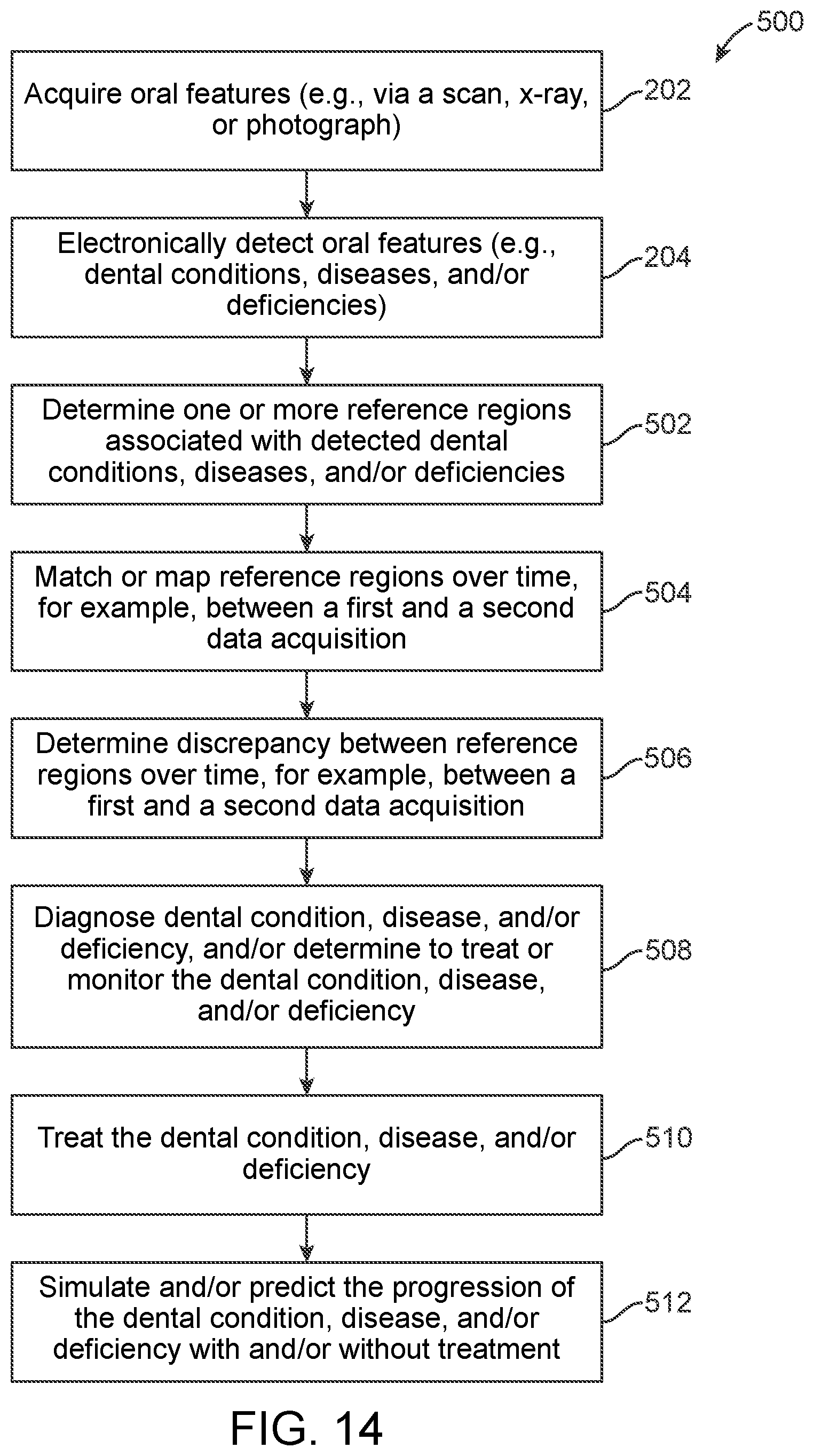
FIG. 14 illustrates a variation of an algorithm executed by the system.
DETAILED DESCRIPTION
Systems and methods are disclosed that can electronically evaluate and document oral features, including dental features, periodontal features, craniofacial features, or any combination thereof. The systems and methods disclosed can examine, analyze, diagnose and document dental structures, deficiencies, and/or diseases, as well as any other condition relating thereto, for example, any condition relating to the masticatory system. Dental structures, deficiencies and diseases are individually and collectively referred to throughout as features and conditions.
The systems and methods disclosed can identify, quantify, analyze and/or map existing conditions, predict the progression of existing conditions, provide a probability for the manifestation of currently non-manifested conditions, provide a recommendation to treat and/or monitor existing conditions, provide a recommendation to treat and/or monitor not yet manifested conditions (e.g., with preventative treatment), identify variables that are contributing to and causing the development of existing and not yet manifested conditions, identify educational protocols that can influence and succeed in changing patient behavior that is causing or is detrimental to dental health or its improvement, identify educational protocols most likely to influence and succeed in changing behavior that is causing or is detrimental to dental health or its improvement specific to the patient, for example, based partly or completely on physiologic, genetic, bacterial, and environmental factors, as well as their health history, or any combination thereof. For example, the systems and methods disclosed can measure, map, diagnose, and/or define the extent of dental deficiencies as well as any other detectable (e.g., scannable, photographable) dental conditions. The mappings disclosed can be visual (e.g., using one-, two-, three-, and/or four-dimensional representations) and/or numeric (e.g., using numbers, ratios, and/or matrices). Three- and four-dimensional representations, for example, can be 3D printed structures and/or 3D computer renderings, with the four-dimensional printed structures and/or renderings including time and/or date indicators. The mappings disclosed can be used to create historical, current, and/or predictive models for the acquired (e.g., scanned, x-rayed, photographed) conditions and/or of healthy structures not associated with a condition.
The systems and methods disclosed can perform structural, physiological, and/or functional analyses of existing conditions. The systems and methods disclosed can analyze data captured from one or multiple data acquisition devices (e.g., one or multiple scanning devices, image capturing devices, video capturing devices, or any combination thereof) and/or systems. For example, the systems and methods disclosed can analyze data recorded by one or multiple intra-oral data acquisition devices (e.g., one or multiple intra-oral scanners, radiograph devices, camera devices, or any combination thereof).
The methods disclosed can include algorithms that can be executed by the system. The algorithms disclosed can use data recorded by and/or retrieved from the one or multiple data acquisition devices and/or from a database, memory, or other storage medium that has the recorded data stored thereon. The algorithms disclosed can measure or otherwise quantify the extent of the areas affected by a condition. The algorithms disclosed can measure or otherwise quantify the extent of the conditions on one or more teeth, for example, on each tooth individually and/or on multiple teeth sequentially and/or simultaneously. The resultant data can be used visually on the existing image or digital representation (e.g., by superimposing the data or a derivative of it on the existing image or digital representation) and/or can be used in a numeric formulation on a tooth-by-tooth and/or entire dentition summary. For example, the resultant data can be used visually on an existing scan (e.g., a previous scan obtained at an earlier patient visit), for example, by superimposing the data or a derivative of it on the earlier acquired scan.
The systems and methods disclosed can electronically document or otherwise store examination and/or analysis results for use in baseline documentation, mapping (e.g., historical mapping, current mapping, predictive mapping), statistical comparisons (e.g., comparisons to the norm), diagnosis, treatment planning, patient education, or any combination thereof. The electronically documented or otherwise stored data can be queried or otherwise retrieved during the evaluation and analysis of subsequent data acquisitions (e.g., scans, radiographs, photographs) to be able to accurately determine the progression of the previously examined conditions, for example, by comparing results of a subsequent data acquisition to the results of one or more previous data acquisitions. The results of a data acquisition (e.g., the initial data acquisition and/or one or more subsequent data acquisitions) can be compared to results previously obtained from the same patient and/or from one or more different patients. The system and methods disclosed can have and/or can build a library of patient-specific and non-patient specific examination and analysis data. Such libraries of data can allow one-time data acquisitions and/or each subsequent data acquisition to be more informative to the patient and medical professional alike. The electronically stored data can allow the system to build dental narratives for one or multiple teeth that can be quickly referenced and provide critical details regarding a person's health that visual inspection of data acquisition results would not provide alone.
The systems and methods disclosed can utilize artificial intelligence and/or machine learning when processing acquired data (e.g., scan data, radiographic data, photograph data), including programming one or more processors with artificial intelligence and/or machine learning software.
In this way, the systems and methods disclosed can provide comprehensive dental examinations that are both accurate and reliable, and which enable existing and not yet manifested conditions to be more easily, accurately, and precisely tracked over time.
The various exemplary variations of the systems and methods disclosed can be interchangeably combined with any other variation disclosed and contemplated herein. Likewise, the various components, features, elements, processes, steps, and/or operations of each exemplary system and/or method disclosed can be interchangeably combined with any other variation disclosed and contemplated herein Although every iteration of the systems and methods disclosed has not been expressly illustrated in the accompanying figures, it will be understood that the accompanying figures are exemplary and non-limiting, and that while absence of a feature does not require its omission, it nevertheless discloses its omission, and hereby provides support for potential future negative limitations in the claims. Any disclosure herein can be combined or modified with any other disclosure herein, even if such a combination is not expressly illustrated in the accompanying figures, as the accompanying figures are exemplary only.
System
FIG. 1 illustrates a schematic of a variation of an electronic dental examination and documentation system 100. The system 100 can have a data acquisition device 102 and an examination unit 104. The data acquisition device 102 can be in wired or wireless communication with the examination unit 104. One or more data acquisition devices 102 can be connected to the examination unit 104. The examination unit 104 can receive data from one or more data acquisition devices 102, for example, separately, sequentially, and/or simultaneously. The data acquisition device 102 can be used to capture or image (e.g., scan, photograph, x-ray) the various oral features disclosed herein, including dental features, periodontal features, craniofacial features, or any combination thereof, including the various hard and soft tissues associated with each. FIG. 1 illustrates that the data acquisition device 102 can acquire the oral features of a patient 101, for example, by electronically capturing or imaging the oral features. The acquiring is indicated by the dotted line that extends between the patient 101 and the data acquisition device 102. The dotted line also represents wired or wireless data transfer to and/or from the data acquisition device 102 and the examination unit 104.
The data acquisition device 102 can be used to create a digital impression of all or part of an oral cavity and the masticatory system. For example, the digital data that the data acquisition device 102 acquires can digitally represent one or more oral features, including the entire dentition, a subset thereof, a single tooth, one or more portions of multiple teeth, a portion of a single tooth, the supporting periodontal and/or craniofacial structures, nerve innervation, blood vessel perfusion, or any combination thereof. In this way, the data acquisition device 102 can be used to digitally record the existing conditions of an oral cavity and the masticatory system, including healthy and unhealthy conditions, as well as conditions that are improving or deteriorating.
The data acquired by one or multiple data acquisition devices 102 can be merged or otherwise combined into a single digital representation (e.g., image), can be kept separate, or can be partitioned and/or combined into multiple digital representations (e.g., images). One or more aspects (e.g., one or more dental features or conditions) recorded by one or multiple data acquisition devices 102 can be merged or otherwise combined into a single digital representation (e.g., an image), can be kept separate, or can be partitioned and/or combined into multiple digital representations (e.g., images). For example, multiple data sets acquired by one or multiple data acquisition devices 102 can be merged or otherwise combined into a single digital representation (e.g., image), can be kept separate, or can be partitioned and/or combined into multiple digital representations (e.g., images), as can multiple data sets representative of one or more aspects (e.g., one or more dental features or conditions) recorded by one or multiple data acquisition devices 102.
The data acquisition device 102 can be a scanner, an x-ray device, a camera, or any combination thereof. For example, the data acquisition device 102 can be a handheld scanner, radiographic imaging device, camera, or any combination thereof. Additionally or alternatively, the data acquisition device 102 can be a scanner, radiographic imaging device, or camera mountable (e.g., mounted) to a wall, floor, and/or ceiling. For example, the system 100 can have or can be capable of utilizing (e.g., receiving data recorded by) one or multiple intra-oral scanners, and/or one or multiple other data acquisition devices. The data acquisition device 102 can be a 3D scanner (e.g., 3D video scanner), a computed tomography (CT) scanner, a confocal imaging scanner, a parallel confocal imaging scanner, a light emitting diode (LED) pattern projection scanner, a laser scanner, a radiographic scanner, or any combination thereof. One or multiple (e.g., two, three, four or more) types of data acquisition devices 102 can be used to acquire dental data for dental condition detection and evaluation. The number and type of data acquisition devices 102 used can depend on the conditions that are sought to be detected, for example, whether soft and/or hard tissues need to be detected, such that the number and type used can advantageously be made on a case-by-case basis to accommodate each person's needs.
The data acquisition device 102 can record digital data having one or multiple images, data slices, and/or videos. The data acquisition device 102 can provide data having any file format, for example, stereolithography (STL) files, DCM files having a DICOM format, graphic interchange format (GIF) files, joint photographic experts group (JPEG) files, tagged image files (TIF), and/or portable network graphics (PNG) files. Such data cannot be prepared in the mind of a dentist and therefore provides more accurate and reliable results than when compared to visual inspection alone.
The examination unit 104 can process data received and/or retrieved from the data acquisition device 102. For example, the examination unit 104 can process images and videos or any other processable representation recorded by the data acquisition device 102. The examination unit 104 can process videos and/or slice video data into one or more smaller sized still images. The examination unit 104 can process acquired data in real-time and/or can process acquired data that was previously stored, for example, in a computer readable storage medium.
The one or more data acquisition devices 102 and the examination unit 104 can provide a comprehensive electronic examination of one or multiple patients (e.g., patient 101).
The examination unit 104 can be local or remote relative to the data acquisition device 102. For example, the examination unit 104 can be on or be part of a server such as a cloud server, a cluster server, and/or a storage server. The examination unit 104 can analyze data from one or multiple data acquisition devices 102 and can be configured to store raw data (e.g., unprocessed data, unanalyzed data), processed data, data derived from raw and/or processed data, or any combination thereof, for example, on a server or on a local memory medium. In this way, the examination unit 104 can electronically "document" examination results and any analyses thereof that can be later referenced by the patient, a medical professional (e.g., dentist), the data acquisition device 102, and/or the examination unit 104. Such storage can be useful for establishing an initial baseline data acquisition that can be analyzed to determine one or more reference points that can be stored to later compare to one or more reference points of one or more subsequent data acquisitions (e.g., scans, radiographs, photographs), thereby enabling electronic tracking and observation of the dentition, the support structures and surrounding tissues, and the conditions, diseases, and/or conditions thereof. The references points can be numerical or visual representations. For example, the reference points can be one or more of the quantifications and/or mappings described herein (e.g., reference locations, reference measurements, reference shapes, reference ratios, reference colors, shades, or tints, reference blood perfusion, or any combination thereof).
FIG. 1 further illustrates that the examination unit 104 can have a processing unit 106, a memory unit 108, and a communication unit 110. The processing unit 106 can be coupled to the memory and communication units 108, 110 through high-speed buses.
The processing unit 106 can include one or more central processing units (CPUs), graphical processing units (GPUs), application-specific integrated circuits (ASICs), field-programmable gate arrays (FPGAs), or any combination thereof. The processing unit 106 can execute software stored in the memory unit 108 to execute the methods, instructions, and/or algorithms described herein. The processing unit 106 can be implemented in a number of different manners. For example, the processing unit 106 can be an embedded processor, a processor core, a microprocessor, a logic circuit, a hardware finite state machine (FSM), a digital signal processor (DSP), or any combination thereof. As a more specific example, the processing unit 104 can be a 32-bit or a 64-bit processor.
The memory unit 108 can store software, data, logs, or any combination thereof. The data stored can be raw data, processed data, data derived from raw and/or processed data, or any combination thereof. For example, the memory unit 108 can store data received from the data acquisition device 102, as well as the output from the processing unit 106 after the data acquisition device 102 data has been analyzed and/or modeled. The memory unit 108 can be an internal memory of the examination unit 104 as shown in FIG. 1, or it can be an external memory, such as a memory residing on a storage node, a cloud server, and/or a storage server.
The memory unit 108 can be a volatile memory or a non-volatile memory. For example, the memory unit 108 can be a non-volatile storage medium such as non-volatile random access memory (NVRAM), flash memory, disk storage, or a volatile storage such as static random access memory (SRAM). The memory unit 108 can be the main storage unit for the examination unit 104.
The communication unit 110 can include one or more wired or wireless communication interfaces. For example, the communication unit 110 can be a network interface card of the examination unit 104. The communication unit 110 can be a wireless modem or a wired modem, for example, a WiFi modem, a 3G modem, a 4G modem, an LTE modem. Alternatively, or in combination, the communication unit 110 can be a Bluetooth.TM. component, a radio receiver, an antenna, or any combination thereof. For example, the communication unit 110 can be a server communication unit. The examination unit 104 can transmit and/or receive data packets and/or messages using the communication unit 110. The communication unit 110 can connect to or communicatively couple with one or more wireless signal transceivers and/or networks.
The examination unit 104 can include an external database 112 separate from, alternative to, and/or additional to the memory 108. The memory 108 and/or the database 112 can be internal and/or external to the examination unit 104, and can each be non-volatile and/or volatile memory. Alternatively, or in combination, the database 112 can be integrated or otherwise combined with the memory 108. The external database 112 can be on or be part of a server, for example, a cloud server, and/or a storage server.
The memory 108 and/or the external database 112 can be configured to store patient-specific data and/or non-patient specific data. For example, the memory 108 can store patient-specific data and the external database 112 can store non-patient specific data recorded from one or more patients different from patient 101.
The examination unit 104 can have one or multiple processing units 106, memories 108, communication units 110, and/or external databases 112.
FIG. 1 also illustrates that the system 100 can have one or more displays 114. The display 114 can display data acquisition results and/or the analyses and mappings thereof. The display 114 can be integrated with the device or system having the examination unit 104 and/or can be part of a standalone device in wired or wireless communication with the examination unit 104. For example, the display 114 can be part of a computer, a smartphone, a tablet, a laptop, a smartwatch, or any combination thereof. The device having the display 114 can be in communication with the data acquisition device 102, one or more other devices, the cloud, and/or one or more networks.
Alternatively, or in combination, the examination unit 104 can be part of or integrated with the device or system having the display 114, including a personal or portable device, for example, a computer, a smartphone, a tablet, a laptop, a smartwatch, or any combination thereof. Executable code can be installed on memory (e.g., memory 108) of the device having the display 114. When the executable code is executed by the device, the device can perform the instructions, processes, methods, and operations disclosed and contemplated herein, such that the device can analyze data acquisition results. For example, a smartphone application can be downloaded onto a smartphone that has executable code configured to carry out the various functions of the examination unit 104. Alternatively, or in combination, executable code can be located on the cloud, for example, on a server. The device (e.g., a smartphone) can query the server to run the executable code on the server to carry out the instructions, processes, methods, and operations disclosed and contemplated herein.
Alternatively, or in combination, the examination unit 104 can comprise downloadable executable code that utilizes existing processing, memory, and data storage features of a device and/or the cloud.
As described above, the examination unit 104 can analyze data captured by one or multiple data acquiring devices and/or systems 102, for example, from one or multiple intra-oral data acquisition devices 102. The examination unit 104 can analyze data from one or multiple data acquisition devices 102 sequentially and/or simultaneously. The examination unit 104 can detect (and distinguish between) healthy and/or unhealthy conditions from the acquired data received, accessed, and/or processed (e.g., scans, radiographs, images, photographs, and/or video). The examination unit 104 can electronically quantify and map the oral cavity, dentition, and supporting hard and soft tissue structures. The examination unit 104 can use these quantifications and mappings to make diagnoses, predictions (e.g., prognoses), and treatment recommendations, as well as for designing treatment plans. For example, the processing unit 106 can identify, quantify, analyze and/or map existing conditions, predict the progression of existing conditions, provide a probability for the manifestation of currently non-manifested conditions, provide a recommendation to treat and/or monitor existing conditions, provide a recommendation to treat and/or monitor not yet manifested conditions (e.g., with preventative treatment), identify variables that are contributing to and causing the development of existing and/or not yet manifested conditions, identify educational protocols that can influence and succeed in changing patient behavior that is causing or is detrimental to dental health or its improvement, identify educational protocols most likely to influence and succeed in changing behavior that is causing or is detrimental to dental health or its improvement specific to the patient, for example, based partly or completely on physiologic, genetic, bacterial, and environmental factors, as well as their health history, or any combination thereof.
Using the processing unit 106, the examination unit 104 can quantify (e.g., measure), map (e.g., model), diagnose, and/or define the extent of dental deficiencies (e.g., functional deficiencies) as well as any other detectable (e.g., scannable, radiographable, photographable) dental conditions. While acquired data can provide a snapshot of the present, the processing unit 106 can "examine" (i.e., analyze) the acquired data to build a "picture" of past and future states with predictive and speculative modeling techniques such as statistical analysis involving comparisons to the norm and other data sets in which the past, present, and/or future states are already known (e.g., from other patients having conditions in the same or different stages and/or having interrelated causes to those conditions being treated or monitored in patient 101). This picture can come in the form of visual and/or numerical mappings as described in more detail below.
The statistical analysis can involve computing one or more statistical parameters, for example, maximums, minimums, medians, averages, norms, standard deviations, or any combination thereof. The statistical analysis can involve generating one or more statistical distributions, for example, discrete probability distributions and/or continuous probability distributions (e.g., normal/Gaussian distributions). The quantifications and mappings can be analyzed to determine one or more statistical parameters and/or to generate one or more statistical distributions. The quantifications and mappings can be statistical parameters and/or distributions. For example, the reference points determined from the data acquisitions can be statistical parameters and/or distributions.
The system 100 (e.g., the examination unit 104) can measure or compute one or more quantities associated with the acquired data, for example, dimensions, quantities associated with qualitative (e.g., color) characterizations, and statistical parameters. For example, the system 100 (e.g., the examination unit 104) can measure or compute one or more quantities representative of or associated with one or more anatomical markers and/or patterns (e.g., exact and/or estimated peaks, valleys, geometries, shapes, lines, perimeters, outlines, or any combination thereof), the relative positions of anatomical markers and/or patterns (e.g., the distances between them, their sizes), the relative positions of dental conditions (e.g., the distances between them, their sizes), the relative positions of hard and soft tissues (e.g., the distances between them, their sizes), light absorption, light reflection, colors (e.g., hues), tints, tones, and shades of colors (e.g., light, medium, and/or dark shades of a hue), changes in any of the foregoing, or any combination thereof.
The system 100 (e.g., the examination unit 104) can generate visual mappings (e.g., using one-, two-, three-, and/or four-dimensional representations) and/or numeric mappings (e.g., using numbers, ratios, and/or matrices) of the acquired data, for example, one or more of the dental conditions digitally represented by the acquired data. The visual and/or numeric mappings can include healthy, diseased, and/or deficient structures and tissues. The system 100 can generate or can produce and send instructions to generate one or more one-, two-, three-, and/or four-dimensional representations of acquired data (e.g., a scan, a radiograph, a photograph). The three- and four-dimensional visualizations can be, for example, 3D printed structures and/or 3D computer renderings, with the four-dimensional printed structures and/or renderings including time and/or date indicators thereon. The mappings can be used to create historical, current, and/or predictive models for the conditions digitally captured by the data acquisition device 102 and/or of healthy structures not associated with a condition. The mappings can be statistical distributions.
Quantifying and/or mapping the oral cavity and masticatory system can involve determining one or more reference parameters or regions (collectively referred to throughout as reference points). Each reference point can be quantitative or qualitative. Each reference point can be a numerical representation and/or a visual representation of a dental condition. For example, the reference points can correspond to one or more reference locations, reference contacts, reference contact regions, reference contact points, reference contact surfaces (e.g., reference occlusal surfaces), reference measurements, reference shapes, reference ratios, reference colors, shades, or tints, reference blood perfusion, or any combination thereof. The reference contacts and reference contact regions/points/surfaces identified by the system 100 can be on a single tooth or can be the areas of engagement between two teeth (e.g., a maxillary tooth and a mandibular tooth). The reference points can correspond to soft tissue having certain characteristics and/or hard tissue having certain characteristics. Such certain characteristics can include, for example, the size, shape, quantity (e.g., mass, volume, etc.), coloration, level of vascular perfusion, structure, structural integrity, or any combination thereof, of soft and/or hard tissue. For example, the reference points can correspond to one or more anatomical markers and/or patterns (e.g., exact and/or estimated peaks, valleys, geometries, shapes, lines, perimeters, outlines, contacts, contact regions/points/surfaces, or any combination thereof), the relative positions of soft and/or hard tissues relative to one another (e.g., the relative positions of one or more anatomical markers to one or more other of the same or different anatomical markers), light absorption, light reflection, colors (e.g., hues), tints, tones, and shades of colors (e.g., light, medium, and/or dark shades of a hue), changes in any of the foregoing, or any combination thereof. For example, the examination unit 104 can differentiate between--and can measure, map, or otherwise determine the extent of--plaque, enamel, dentin, pulp, gum, cement, nerves (e.g., innervation), blood vessels, bone, restorative materials, bacteria, or any combination thereof. The reference point identified by the system 100 can be exposed dentin, for example an exposed spot or area of dentin. As another example, the examination unit 104 can differentiate between the crown, neck, and/or root of each tooth, and can measure, map, or otherwise determine the extent of each. The reference point identified by the system 100 can be a ditch around the cervical margin. The distance between reference points can be determined by comparing a first and a subsequent reference point, for example using photogrammetry techniques. The reference points can be the quantifications and mappings described herein. The reference points can be separate from the quantifications and mappings described herein. The reference points can be derived (e.g., via the examination unit 104) from the quantifications and mappings described herein. To determine the reference points, the system 100 can determine one or more potential reference points, for example, by determining a potential subsequent (e.g., maximum) extent of the of the reference point.
The reference points can be independent from one another, for example, such that each reference point can be separately displayed or communicated to a user. The reference points can be layered (e.g., simultaneously displayed or communicated to a user). For example, one or more reference measurements can be displayed on a 2D visual representation of the dentition having colors indicative of where each dental condition is located. Each type of a dental condition can be associated with a different color, shade, tint, or hash markings.
The reference points of two different data acquisitions (e.g., a first data acquisition and a subsequent data acquisition) can be compared with one another to determine the progression of the identified conditions, including more than two data acquisitions (e.g., 3 to 50 data acquisitions, or more narrowly, 3 to 20 data acquisitions, or more narrowly still, 3 to 10 data acquisitions, or even more narrowly, 3 to 5 data acquisitions). This advantageously enables electronic tracking and observation of the dentition, the support structures and surrounding tissues, and the conditions, diseases, and/or conditions thereof.
The reference points can be a reference region that includes only the area or condition of interest (e.g., a contact area, exposed dentin, wear surface, or any combination), or a region slightly beyond the area or condition of interest. For example, a two-dimensional shape (e.g., a circle, an ellipse, a hemisphere, a triangle, square, rectangle, pentagon, hexagon, or other polygonal shape, including a series of connected line segments forming a closed shape, where the line segments can be straight and/or form one or more arcs), or a three-dimensional shape (e.g., sphere, spheroid, hemispheroid, ellipsoid, or three-, four-, five, six-, seven-, or more-sided prism) can extend around (e.g., around a center, a first end, a second end) of the area/condition of interest in a cross-sectional view and a three-dimensional view, respectively.
The two- or three-dimensional shape can include the area/condition of interest and an area beyond that area. For example, the shape can extend at a constant or variable distance beyond a boundary of the contact area, for example, from about 0.1 mm to about 5.0 mm, including every 0.1 mm increment therebetween. Using a two-dimensional shape to surround the area or condition of interest i
D00000
D00001
D00002
D00003
D00004
D00005
D00006
D00007
D00008
D00009
XML
uspto.report is an independent third-party trademark research tool that is not affiliated, endorsed, or sponsored by the United States Patent and Trademark Office (USPTO) or any other governmental organization. The information provided by uspto.report is based on publicly available data at the time of writing and is intended for informational purposes only.
While we strive to provide accurate and up-to-date information, we do not guarantee the accuracy, completeness, reliability, or suitability of the information displayed on this site. The use of this site is at your own risk. Any reliance you place on such information is therefore strictly at your own risk.
All official trademark data, including owner information, should be verified by visiting the official USPTO website at www.uspto.gov. This site is not intended to replace professional legal advice and should not be used as a substitute for consulting with a legal professional who is knowledgeable about trademark law.