Forward link power control
Bhave , et al.
U.S. patent number 10,587,333 [Application Number 15/840,400] was granted by the patent office on 2020-03-10 for forward link power control. This patent grant is currently assigned to Inmarsat Global Limited. The grantee listed for this patent is Inmarsat Global Limited. Invention is credited to David Bath, Paven Bhave, Richard Locke, Patrick Sharkey.


| United States Patent | 10,587,333 |
| Bhave , et al. | March 10, 2020 |
Forward link power control
Abstract
A method of forward link power control in a communications system comprises: grouping a plurality of user terminals into a plurality of groups, at least one of which comprises more than one of the user terminals; for each said group, determining a corresponding forward link power level required to satisfy an aggregate demand of the group; and assigning one or more forward link carriers to the group, with the corresponding power level.
| Inventors: | Bhave; Paven (London, GB), Sharkey; Patrick (London, GB), Bath; David (London, GB), Locke; Richard (London, GB) | ||||||||||
|---|---|---|---|---|---|---|---|---|---|---|---|
| Applicant: |
|
||||||||||
| Assignee: | Inmarsat Global Limited
(London, GB) |
||||||||||
| Family ID: | 58222140 | ||||||||||
| Appl. No.: | 15/840,400 | ||||||||||
| Filed: | December 13, 2017 |
Prior Publication Data
| Document Identifier | Publication Date | |
|---|---|---|
| US 20180167135 A1 | Jun 14, 2018 | |
Foreign Application Priority Data
| Dec 13, 2016 [GB] | 1621173.2 | |||
| Current U.S. Class: | 1/1 |
| Current CPC Class: | H04W 52/18 (20130101); H04L 1/0003 (20130101); H04L 1/0009 (20130101); H04B 7/18513 (20130101); H04W 52/42 (20130101); H04L 1/0015 (20130101); H04W 52/346 (20130101); H04B 7/18543 (20130101); H04B 7/18519 (20130101) |
| Current International Class: | H04B 7/185 (20060101); H04W 52/42 (20090101); H04W 52/18 (20090101); H04L 1/00 (20060101); H04W 52/34 (20090101) |
References Cited [Referenced By]
U.S. Patent Documents
| 4119964 | October 1978 | Johannsen et al. |
| 4228538 | October 1980 | Scharla-Nielsen et al. |
| 4261054 | April 1981 | Scharla-Nielsen |
| 4567485 | January 1986 | Oshima et al. |
| 4691882 | September 1987 | Young |
| 4731866 | March 1988 | Muratani et al. |
| 4905235 | February 1990 | Saburi |
| 4910792 | March 1990 | Takahata et al. |
| 4941199 | July 1990 | Saam |
| 5073900 | December 1991 | Mallinckrodt |
| 5257019 | October 1993 | Schwendeman et al. |
| 5257029 | October 1993 | Miyo |
| 5285208 | February 1994 | Bertiger et al. |
| 5339330 | August 1994 | Mallinckrodt |
| 5446756 | August 1995 | Mallinckrodt |
| 5612703 | March 1997 | Mallinckrodt |
| 5619525 | April 1997 | Wiedeman et al. |
| 5678175 | October 1997 | Stuart et al. |
| 5697056 | December 1997 | Tayloe |
| 5710982 | January 1998 | Laborde et al. |
| 5754942 | May 1998 | Wachs |
| 5765098 | June 1998 | Bella |
| 5790940 | August 1998 | Laborde et al. |
| 5828947 | October 1998 | Michel et al. |
| 5832379 | November 1998 | Mallinckrodt |
| 5835846 | November 1998 | Furukawa et al. |
| 5835847 | November 1998 | Gilmore et al. |
| 5835857 | November 1998 | Otten |
| 5864547 | January 1999 | Strodtbeck et al. |
| 5878329 | March 1999 | Mallinckrodt |
| 5924015 | July 1999 | Garrison |
| 5940753 | August 1999 | Mallinckrodt |
| 5951709 | September 1999 | Tanaka |
| 5956619 | September 1999 | Gallagher et al. |
| 5963862 | October 1999 | Adiwoso |
| 5978363 | November 1999 | Dimitrijevic et al. |
| 5995832 | November 1999 | Mallinckrodt |
| 6021309 | February 2000 | Sherman et al. |
| 6081710 | June 2000 | Sherman et al. |
| 6085067 | July 2000 | Gallagher et al. |
| 6091933 | July 2000 | Sherman et al. |
| 6097752 | August 2000 | Wiedeman et al. |
| 6108561 | August 2000 | Mallinckrodt |
| 6157811 | December 2000 | Dent |
| 6163679 | December 2000 | Bakke et al. |
| 6219528 | April 2001 | Wright et al. |
| 6240124 | May 2001 | Wiedeman et al. |
| 6272325 | August 2001 | Wiedeman et al. |
| 6317585 | November 2001 | Shibasaki |
| 6321065 | November 2001 | Wilcoxson et al. |
| 6328264 | December 2001 | Maeda et al. |
| 6352222 | March 2002 | Maeda et al. |
| 6422516 | July 2002 | Maeda et al. |
| 6430418 | August 2002 | Nivens et al. |
| 6477355 | November 2002 | Grayson et al. |
| 6490448 | December 2002 | Hogberg et al. |
| 6499698 | December 2002 | Maeda et al. |
| 6615052 | September 2003 | Parmenter |
| 6628920 | September 2003 | Wolcott |
| 6634602 | October 2003 | Maeda et al. |
| 6684057 | January 2004 | Karabinis |
| 6711398 | March 2004 | Talaie et al. |
| 6760566 | July 2004 | Wright et al. |
| 6764049 | July 2004 | Maeda et al. |
| 6824107 | November 2004 | Maeda et al. |
| 6829226 | December 2004 | Apostolides et al. |
| 6839540 | January 2005 | Katzur |
| 6982964 | January 2006 | Beering |
| 6985716 | January 2006 | Talaie et al. |
| 6996077 | February 2006 | Suenaga et al. |
| 7043199 | May 2006 | Dai et al. |
| 7047029 | May 2006 | Godwin et al. |
| 7116936 | October 2006 | Kim |
| 7120434 | October 2006 | Talaie et al. |
| 7194270 | March 2007 | Smith |
| 7254117 | August 2007 | Choi et al. |
| 7289460 | October 2007 | Thacker et al. |
| 7386310 | June 2008 | Dai et al. |
| 7450602 | November 2008 | Vazquez Castro |
| 7599659 | October 2009 | Wang et al. |
| 7633895 | December 2009 | Schiff et al. |
| 7639981 | December 2009 | Karabinis |
| 7715788 | May 2010 | Lozano |
| 7720136 | May 2010 | Friedman et al. |
| 7782811 | August 2010 | Battista et al. |
| 7783287 | August 2010 | Karabinis |
| 7929482 | April 2011 | Tian et al. |
| 7933215 | April 2011 | Schiff et al. |
| 7974576 | July 2011 | Martin et al. |
| 8010043 | August 2011 | Miller |
| 8068827 | November 2011 | Miller et al. |
| 8107875 | January 2012 | Miller |
| 8131212 | March 2012 | Laufer |
| 8144643 | March 2012 | Miller et al. |
| 8155584 | April 2012 | Wang et al. |
| 8179778 | May 2012 | Kim et al. |
| 8189504 | May 2012 | Becker et al. |
| 8195090 | June 2012 | Treesh et al. |
| 8213929 | July 2012 | Miller et al. |
| 8218476 | July 2012 | Miller |
| 8238817 | August 2012 | Avellan et al. |
| 8254303 | August 2012 | Becker et al. |
| 8254832 | August 2012 | Dankberg et al. |
| 8270898 | September 2012 | Karabinis et al. |
| 8285202 | October 2012 | Miller |
| 8300571 | October 2012 | Becker et al. |
| 8315199 | November 2012 | Dankberg et al. |
| 8320296 | November 2012 | Becker et al. |
| 8369776 | February 2013 | Karabinis et al. |
| 8374118 | February 2013 | Becker et al. |
| 8385223 | February 2013 | Miller et al. |
| 8401038 | March 2013 | Becker et al. |
| 8411615 | April 2013 | Hong et al. |
| 8428000 | April 2013 | Battista et al. |
| 8447295 | May 2013 | Palmer et al. |
| 8483609 | July 2013 | Miller |
| 8509144 | August 2013 | Miller et al. |
| 8538323 | September 2013 | Dankberg et al. |
| 8547863 | October 2013 | Miller et al. |
| 8548337 | October 2013 | Taylor |
| 8576767 | November 2013 | Ravishankar et al. |
| 8600296 | December 2013 | Miller |
| 8699465 | April 2014 | Tian et al. |
| 8712321 | April 2014 | Dankberg |
| 8726133 | May 2014 | Hong et al. |
| 8737925 | May 2014 | Beeler et al. |
| 8774731 | July 2014 | Brown et al. |
| 8792821 | July 2014 | Treesh et al. |
| 8804857 | August 2014 | Kim et al. |
| 8805390 | August 2014 | Swardh et al. |
| 8831598 | September 2014 | Clemmensen et al. |
| 8855552 | October 2014 | Dankberg et al. |
| 8879982 | November 2014 | Jayasimha et al. |
| 8891434 | November 2014 | Becker et al. |
| 8897207 | November 2014 | Argov et al. |
| 8897769 | November 2014 | Miller et al. |
| 8977191 | March 2015 | Jong et al. |
| 9009338 | April 2015 | Dankberg |
| 9009762 | April 2015 | Kim et al. |
| 9014620 | April 2015 | Dankberg |
| 9025679 | May 2015 | Ryu et al. |
| 9026106 | May 2015 | Livergood |
| 9036661 | May 2015 | Becker et al. |
| 9037078 | May 2015 | Karabinis |
| 9077428 | July 2015 | Tronc |
| 9086471 | July 2015 | Mengwasser |
| 9088335 | July 2015 | Jong et al. |
| 9124342 | September 2015 | Beeler et al. |
| 9172457 | October 2015 | Dankberg et al. |
| 9176213 | November 2015 | Liu et al. |
| 9184829 | November 2015 | Miller et al. |
| 9198077 | November 2015 | Park |
| 9198126 | November 2015 | Topping et al. |
| 9203431 | December 2015 | Lee et al. |
| 9203504 | December 2015 | Zakaria et al. |
| 9246576 | January 2016 | Yanai et al. |
| 9300391 | March 2016 | Ravishankar et al. |
| 9319128 | April 2016 | Yamamoto et al. |
| 9356685 | May 2016 | Angeletti et al. |
| 9357508 | May 2016 | Elinav et al. |
| 9379806 | June 2016 | Mandell et al. |
| 9391690 | July 2016 | Jong et al. |
| 9485010 | November 2016 | Chen et al. |
| 9496946 | November 2016 | Battista et al. |
| 10110300 | October 2018 | Xu |
| 2002/0137457 | September 2002 | Nivens et al. |
| 2003/0083089 | May 2003 | Malladi |
| 2004/0033780 | February 2004 | Kelly |
| 2004/0116134 | June 2004 | Maeda et al. |
| 2005/0117610 | June 2005 | Chevallier et al. |
| 2005/0288012 | December 2005 | Morgan |
| 2008/0159419 | July 2008 | Smith |
| 2012/0058797 | March 2012 | Peter et al. |
| 2012/0120869 | May 2012 | Miller |
| 2012/0282922 | November 2012 | Fodor |
| 2012/0294230 | November 2012 | Dankberg et al. |
| 2013/0157560 | June 2013 | Blau et al. |
| 2013/0222179 | August 2013 | Jeong |
| 2013/0309961 | November 2013 | Lim et al. |
| 2014/0056335 | February 2014 | Ryu et al. |
| 2014/0064118 | March 2014 | Hong et al. |
| 2014/0198721 | July 2014 | Walker et al. |
| 2014/0199940 | July 2014 | Dockemeyer, Jr. et al. |
| 2014/0211722 | July 2014 | Pietraski |
| 2015/0031408 | January 2015 | Kalla |
| 2015/0139072 | May 2015 | Hong et al. |
| 2015/0215029 | July 2015 | Lemme |
| 2016/0072613 | March 2016 | Esserman |
| 2016/0191145 | June 2016 | Fang et al. |
| 2016/0195618 | July 2016 | Baer et al. |
| 2016/0218796 | July 2016 | Ryu |
| 2016/0242066 | August 2016 | Ryu |
| 2016/0274240 | September 2016 | Wheatley |
| 2016/0277096 | September 2016 | Ryu |
| 2016/0278063 | September 2016 | Zhang et al. |
| 2016/0308603 | October 2016 | Hirsch et al. |
| 104581918 | Apr 2015 | CN | |||
| 3824338 | Dec 1992 | DE | |||
| 3642213 | Jan 1994 | DE | |||
| 0416462 | Mar 1991 | EP | |||
| 0790715 | Jun 1997 | EP | |||
| 116866 | Jan 2002 | EP | |||
| 1168663 | Jan 2002 | EP | |||
| 1199828 | Apr 2002 | EP | |||
| 2073400 | Dec 2011 | EP | |||
| 2611043 | Jul 2013 | EP | |||
| 2745673 | Apr 1998 | FR | |||
| 2348339 | Mar 2001 | GB | |||
| H02-280424 | Nov 1990 | JP | |||
| WO 95/13671 | May 1995 | WO | |||
| WO 01/05063 | Jan 2001 | WO | |||
| WO 02/21725 | Mar 2002 | WO | |||
| WO 02/078216 | Oct 2002 | WO | |||
| WO 2004/057777 | Jul 2004 | WO | |||
| WO 2004/100501 | Nov 2004 | WO | |||
| WO 2007/021155 | Feb 2007 | WO | |||
| WO 2007/071059 | Jun 2007 | WO | |||
| WO 2007/082719 | Jul 2007 | WO | |||
| WO 2009/078539 | Jun 2009 | WO | |||
| WO 2010/054394 | May 2010 | WO | |||
| WO 2010/097349 | Sep 2010 | WO | |||
| WO 2014/084464 | Jun 2014 | WO | |||
Other References
|
Combined Search and Examination Report for GB1621173.2, dated Dec. 13, 2016, 3 pages. cited by applicant . European Search Report directed to European Patent Application No. EP 17 20 6824, completed May 3, 2018, 2 pages. cited by applicant. |
Primary Examiner: Hailu; Kibrom T
Attorney, Agent or Firm: Sterne, Kessler, Goldstein & Fox P.L.L.C.
Claims
What is claimed is:
1. A method of forward link power control in a wireless communication system, the method comprising: a. for each of a plurality of user terminals, determining a respective forward link demand of that user terminal; b. grouping the plurality of user terminals into a plurality of groups according to said determined forward link demands of each of the user terminals, wherein at least one of the groups comprises more than one of the user terminals; c. for each said group, determining a corresponding forward link power level required to satisfy an aggregate of said determined forward link demands of each of the user terminals within that group, and assigning one or more forward link carriers to the group, with the corresponding forward link power level.
2. The method of claim 1, wherein grouping the user terminals includes sorting the user terminals by said determined forward link demands of each of the user terminals and segregating the user terminals into the plurality of groups.
3. The method of claim 1, wherein said forward link demands are determined from corresponding forward data queue lengths for each of said terminals.
4. The method of claim 1, wherein said forward link demands are determined from corresponding demand requirements received from each of the user terminals.
5. The method of claim 1, wherein at least one of the groups comprises a single said user terminal having a higher determined forward link demand than other ones of the user terminals.
6. The method claim 1, wherein the user terminals are additionally grouped by geographic location.
7. The method of claim 1, wherein the wireless communication system is a satellite communications system.
8. The method of claim 7, wherein the user terminals are arranged in a plurality of beams in which the carriers may be re-used subject to a minimum re-use distance.
9. The method of claim 1, wherein the number of groups is limited to a predetermined maximum.
10. The method of claim 1, wherein the forward link power levels are constrained by a maximum aggregate power level.
11. The method of claim 1, wherein the power level comprises an EIRP.
12. The method of claim 1, wherein the carriers comprise frequency channels.
13. The method of claim 1, including assigning a corresponding coding and/or modulation rate to each of the forward link carriers.
14. The method of claim 1, including transmitting to the user terminals using the forward link carriers with the corresponding power levels.
15. The method of claim 1, wherein each said group is assigned to a corresponding one of the forward link carriers.
16. The method of claim 8, wherein a plurality of said groups of user terminals are located within the same one of said beams.
17. A wireless communication system comprising: a plurality of user terminals; and a transmitter arranged to transmit wireless signals to the plurality of user terminals over a forward link; wherein a respective forward link demand is determined for each of the user terminals, and the user terminals are grouped into a plurality of groups according to said determined forward link demands of each of the user terminals, wherein at least one of the groups comprises more than one of the user terminals; for each said group, a corresponding forward link power level required to satisfy an aggregate of said determined forward link demands of each of the user terminals within that group is determined, and one or more forward link carriers are assigned to the group, with the corresponding forward link power level.
18. A non-transient computer readable medium containing program instructions for causing a computer to: a. for each of a plurality of user terminals, determine a forward link demand of that user terminal; b. group the plurality of wireless user terminals into a plurality of groups according to said determined forward link demands of each of the user terminals, wherein at least one of the groups comprises more than one of the user terminals; c. for each said group, determine a corresponding forward link power level required to satisfy an aggregate of said determined forward link demands of each of the user terminals within that group, and assign one or more forward link carriers to the group, with the corresponding forward link power level.
Description
FIELD OF THE INVENTION
The present invention relates to a method and apparatus for power control in a forward link of a communication system, particularly but not exclusively a satellite communications system.
BACKGROUND OF THE INVENTION
Many satellite communications systems have Adaptive Coding and Modulation (ACM) that aim to maximize the throughput of a forward link (i.e. for transmission to a user terminal (UT)). An example system is disclosed in US2014/0056335 A1.
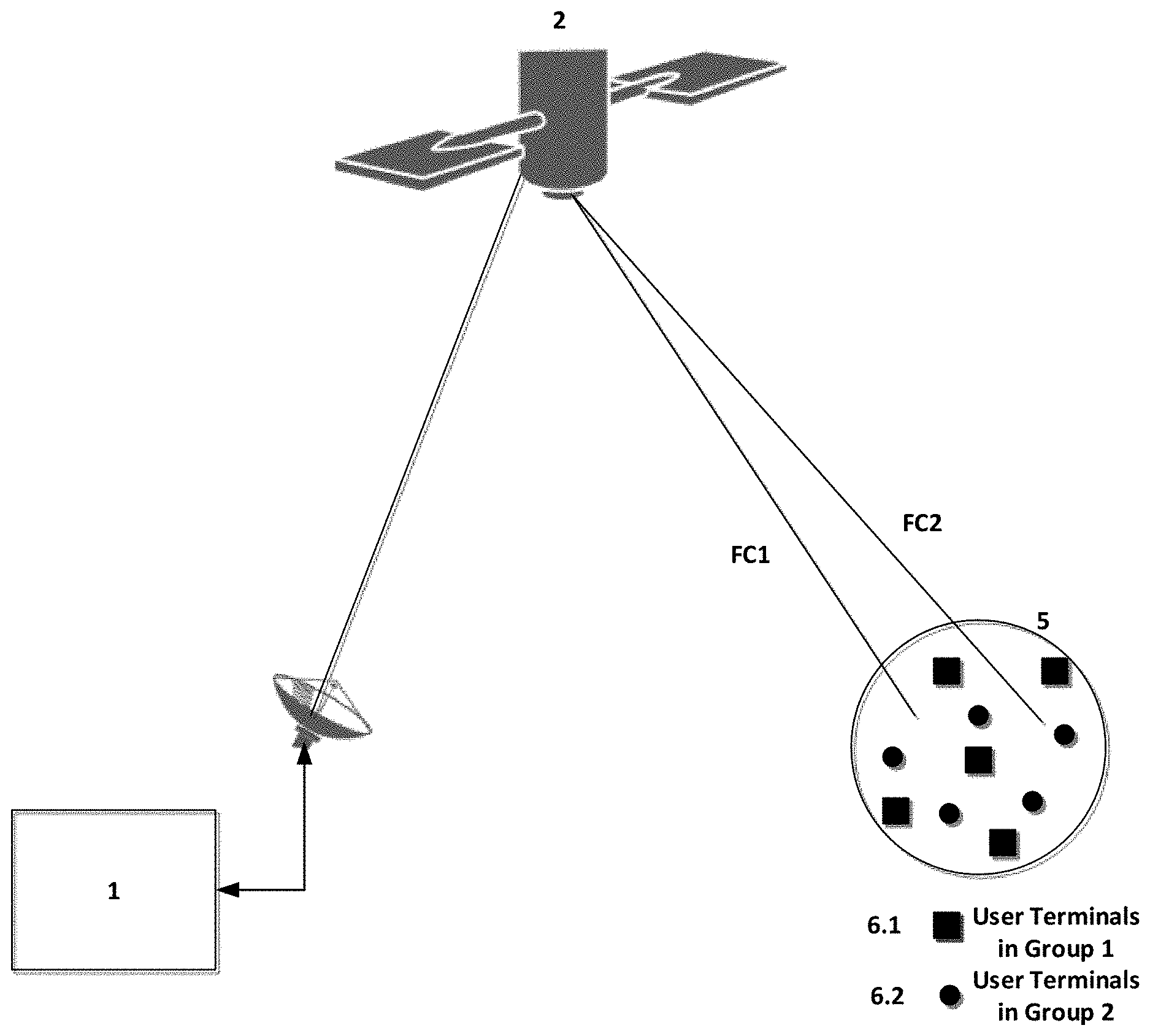
FIG. 1 depicts a satellite communication system comprising a ground station 1 that transmits uplink signals UL to a satellite 2, which transmits corresponding downlink signals DL in one or more beams. A plurality of UTs (User Terminals) 6 in a beam 5 are served by two forward carriers FC1 and FC2. The forward carriers FC1, FC2 are shared between multiple user terminals 6. In a typical satellite communication network both the forward carriers FC1, FC2 will operate with a fixed EIRP (Effective Isotropic Radiated Power).
Consider an example where a UT 6 is making a voice over internet-protocol (VOIP), and is in an area where there is excellent signal strength. In a conventional ACM method the UT 6 will report its link conditions and the network will adapt the code rate and modulation so that the user can achieve maximum data rate. However, the UT 6 only requires a sufficient data rate to make a VOIP call, whereas the maximum data rate may only be required if the UT 6 is streaming real time data. Hence, the conventional approach to ACM may not give the optimum overall system performance.
SUMMARY OF THE INVENTION
Aspects of the present invention are defined by the accompanying claims. Embodiments of the invention include a method to optimise the system performance for given aggregate satellite power in the forward direction. This method may maximise total system throughput, rather than per user throughput in cases where the forward link is shared with a plurality of users.
Embodiments of the invention may use an algorithm that overcomes the conventional mismatch of requirements by adjusting the forward carrier EIRP.
The method may maintain equilibrium between ACM and optimisation of system capacity, for example by grouping of user terminals based on demand and/or geographic location, optimising the forward link power control such that the demand for each group is met, and balancing the total power available to optimise the link per user terminal group.
Optimising the forward link power may involve one or more of the following benefits. First, power distribution is no longer fixed so that user terminal groups with higher demand can be serviced with a higher power. Second, some user links may be operated with a lower power than in a conventional ACM method, which leads to reduction in interference, further improving system performance.
BRIEF DESCRIPTION OF THE DRAWINGS
Specific embodiments of the present invention will now be described with reference to the accompanying drawings, in which:
FIG. 1 is a diagram of a satellite communication system using a conventional ACM method;
FIG. 2 is a diagram of a satellite communication system using an ACM method according to an embodiment of the invention;
FIG. 3 is a flowchart of the ACM method in the embodiment; and
FIG. 4 is a diagram illustrating a specific use example of the embodiment.
DETAILED DESCRIPTION OF EMBODIMENTS
Apparatus for use in an embodiment of the invention is shown in FIG. 2, in which similar parts to those in FIG. 1 carry the same reference numerals.
In the following discussion, the term `carrier` may refer to a frequency channel having a predetermined bandwidth. The carrier may be shared between different UTs 6, for example using time slots in a TDMA system or spreading codes in a CDMA system.
The ground station 1 is arranged to maintain a record of demand from the UTs 6, for example from forward data queue length and/or demand requirements received from the UTs 6. The ground station 1 and/or the satellite 2 are able to adjust independently the power (e.g. EIRP) of each forward link carrier, for example for the forward carriers FC1, FC2.
The ground station periodically runs the algorithm shown in FIG. 3 to achieve optimised system capacity. Step S1 is a trigger event to start the method. The trigger can be a periodic time to wake up the ground station 1 to run the algorithm or an event such as addition of a new UT to the pool. The next step S2 is to group the UTs 6. The ground station 1 monitors the forward data queue and any pre-negotiated demand parameters for a particular UT to calculate the user terminal demand in the forward link. The ground station 1 then sorts the UTs 6 based on their traffic demand. The grouping is then done based on segregating the UTs into groups 6.1 and 6.2. There may be more than 2 groups, but preferably the number of groups is limited to a maximum predefined value.
In Step S3 the ground station 1 calculates the maximum EIRP needed within a group 6.1, 6.2 to satisfy the demands of every UT within that group.
In step S4 the power control function of the satellite 2 and/or the ground station 1 is used to adjust the EIRP for each forward link FC1, FC2, preferably subject to the following constraints.
Constraints
Let there be a maximum of .theta.max groups per beam 5 and let up.sub.i.theta.j be the EIRP required to achieve a data rate dr.sub.i.theta.j for user.sub.i.theta.j where i=i.sup.th user and .theta.j=j.sup.th user group.
Constraint 1: Total Beam Power
.theta..times..times..times..theta..times..times..ltoreq..times..times..t- imes..times..times..times..times..times..times..times..times..times..times- ..times. ##EQU00001## Where up.sub..theta.jmin is the minimum power required in the j.sup.th user group to attain max(dr.sub.i.theta.j). Constraint 2: Aggregate EIRP
.theta..times..times..times..ltoreq..times..times..times..times..times..t- imes..times..times..times..times..times..times..times..times..times..times- . ##EQU00002## Algorithm
An example of the method of FIG. 3 will now be described as an algorithm.
Start S1:
init_qos.sub.i=Read QoS per User cno.sub.current.sup.i=Read CNo for User "i" capacity.sub.carrier.sup.i=lookupdatarate(min (cno.sub.current.sup.i),ue_type) Look-up Table for Data-rate or carrier to Noise Ratio For each User Equipment Type the network will store a look up table mapping of the CNo and Datarate, for example as shown below. LookupDataRate(Look up value, UT Type)
TABLE-US-00001 Type Sub Type C/No Data Rate T5X4 L8 51.5 110.7 T5X4 L7 52.6 135 T5X4 L6 53.75 162 T5X4 L5 54.72 190.8 T5X4 L4 55.77 220.5 T5X4 L3 56.83 250.2 T5X16 L2 57.35 270 T5X16 L1 58.43 315 T5X16 R 59.53 360 T5X16 H1 60.50 400.5 T5X16 H2 61.50 441 T5X16 H3 62.48 486 T5X16 H4 63.74 531 T5X16 H5 64.80 559.8 T5X16 H6 65.45 576 T5X64 H2 66.25 634.4 T5X64 H3 67.45 702 T5X64 H4 68.64 767 T5X64 H5 69.75 819 T5X64 H6 70.95 858
Where Type indicates the modulation type (the number after `X` indicating the number of possible modulation symbols), and Sub Type indicates the FEC coding rate. Group Users S2:
TABLE-US-00002 cno.sub.required.sup.i = lookupdatarate(init_qos.sub.i, ue.sub.type) deficit.sup.i = cno.sub.current.sup.i - cno.sub.required.sup.i sort_user.sub.i = sorthightolow(deficit) Let qos.sub.i = init_qos.sub.i of sort_user.sub.i .times. ##EQU00003## n = 0 Loop1: i = 0 loop2: If(cum.sup.i/capacity.sub.carrier.sup.n > 0): capacity.sub.group.sup.n = cum.sup.i user.sub.n.sup.i = sort_user.sub.i Increment i Else: Exit loop1 End of If: End of loop2: total_carriers = n Increment n End of loop1:
Calculate EIRP S3:
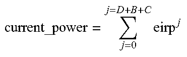
TABLE-US-00003 groupcno.sub.required.sup.n = lookupdatarate(capacity.sub.group.sup.n, ue.sub.type) user.sub.n.sup.least_capable = Read CNo for least capable UT in Group 'n' cno_deficit.sup.n = user.sub.n.sup.least_capable - groupcno.sub.required.sup.n For all Carriers If cno_deficit.sup.n = 0 then don't do anything for this carrier If cno_deficit.sup.n > 0: Add carrier to the list `dec_power` as the carier power has to be decreased Else: Add carrier to the list `inc_power` as the carrier power has to be increased Let D = number of carriers that have to be decreased in power, B be the total number of carriers that have to be increased in power and C be the total number of carriers that do not need any power change Loop: For each carrier (n = 1 to D) that needs power decrease eirp.sup.n = Read EIRP of carrier 'n' user.sub.n.sup.least_capable = Read CNo for least capable UE in Group 'n' delta_cno.sup.n = user.sub.n.sup.least_capable - groupcno.sub.required.sup.n If delta_cno.sup.n = 0 D = D - 1 Remove carrier for list of acrriers to be reduced Else: power_adjust.sup.n = delta_cno.sup.n * .alpha. where .alpha. is the convergence factor < 1 Adjust_EIRP (carrier.sup.n, - power.sub.adjust.sup.n) For each carrier (n = 1 to B) that need power increase eirp.sup.n = Read EIRP of carrier 'n' .times. ##EQU00004## available_power = Max EIRP per Beam - current_power power_adjust.sup.n = available_power/B Adjust_EIRP ( carrier.sup.n, power.sub.adjust.sup.n) Decrement D If D = 0 Exit Loop: End of Loop:
Adjust EIRP S4:
TABLE-US-00004 Adjust_EIRP ( carrier.sup.n, power.sub.adjust.sup.n) If power.sub.adjust.sup.n < Satellite_power_Adjust_Threshold satellite_carrier_eirp.sup.n = satellite_carrier_eirp.sup.n + power_adjust.sup.n Else power.sub.adjust.sup.n > Satellite_power_Adjust_Threshold satellite_carrier_eirp.sup.n = satellite_carrier_eirp.sup.n + Satellite_power_Adjust_Threshold power_adjust.sup.n = power_adjust.sup.n - Satellite_power_Adjust_Threshold SAS_carrier_eirp.sup.n = SAS_carrier_eirp.sup.n + power_adjust.sup.n
End S5: End Algorithm
Specific Use Example
A specific use example will now be described with reference to FIG. 4, which shows a beam pattern of a satellite network utilising a four-colour re-use scheme. In other words, carriers are assigned into four groups, with the groups being re-used between different beams having a minimum separation.
In an example, there are 3 users in each of Beam A and Beam B, with symmetric demands. For ease of link analysis, the beam isolation at all points is assumed to be the same. The user demands are as shown in Table 1 below.
TABLE-US-00005 TABLE 1 User Demands Max QoS kbps User Service Type requested User 1A and 1B Voice Call 24 User 2A and 2B Streaming 128 User 3A and 3B High Quality Video 858
The system will assign two full carriers F1 and F2 to users 3B and 3A respectively as they demand the maximum throughput that can be achieved by the system. Users 1A and 2A can be served on the same frequency as their maximum aggregate rate is 152 kbps which can be served with one carrier.
As the frequencies can be re-used, Users 1A and 1B are assigned frequency F1 and Users 2A and 2B are assigned frequency F2. In a conventional scenario the network will set both carriers with the same EIRP, for example 41.5 dBW. The conventional ACM allocates the best possible modulation and code rate. Table 2 details the link analysis for such a situation.
TABLE-US-00006 TABLE 2 Link analysis for all carriers with equal EIRP Max QoS EIRP CCI EIRP C/No Throughput Beam Frequency Users kbps dBW dBW dBHz Code Rate kbps A F1 1A-F1 24 41.5 41.5 64.5 T5X16-H4 531 2A-F1 128 F2 3A-F2 856 41.5 41.5 64.5 T5X16-H4 531 B F2 1B-F2 24 41.5 41.5 64.5 T5X16-H4 531 2B-F2 128 F1 3B-F1 856 41.5 41.5 64.5 T5X16-H4 531
The total power used by the two beams A and B is 47.5 dBW and the useful aggregate Data Rate is 1366 kbps.
In contrast, an implementation of the algorithm in an embodiment of the invention will now be described. The network has the information that Users 1A and 1B need a maximum of 24 kbps (IP voice) and Users 2A and 2B need a maximum of 128 kbps streaming rate i.e. an aggregate maximum of 152 kbps. Therefore the network can lower the power for those carriers. On the other hand users 3A and 3B need 858 kbps, which they cannot achieve. Therefore, the network will have to increase the power. The network optimises management of the co-channel interference and the required data rate, and adjusts the carrier powers as shown below, maintaining the same total power per beam.
TABLE-US-00007 TABLE 3 Link analysis for all carriers with optimised EIRP Max QoS EIRP CCI EIRP C/No Throughput Beam Frequency Users kbps dBW dBW dBHz Code Rate kbps A F1 1A-F1 24 31.5 44 54.4 T5X4-L6 162 2A-F1 128 F2 3A-F2 856 44 31.5 67.6 T5X64-H3 702 B F2 1B-F2 24 31.5 44 54.4 T5X4-L6 162 2B-F2 128 F1 3B-F1 856 44 31.5 67.6 T5X64-H3 702
The total power used in the total beams is almost the same as in the conventional case (the embodiment requires 0.25 dB less). The total data rate achieved is 1708 kbps i.e. 25% increase in total capacity for the two beams. In addition, the maximum per-user throughput goes up by 32% from 531 kbps to 702 kbps.
The application of the algorithm in the embodiment to the above example will now be described.
Start S1:
Each User signals their Max QoS (Quality of Service):
1A, 1B Signals 24 kbps
2A, 2B signals 128 kbps
3A, 3B signals 858 kbps
The RAN records the current CNo for each user. For simplicity in this example, they all have a CNo of 64.4 dBHz
Current max capacity of each current carrier=531 kps
Group Users S2:
The required CNo is obtained from a look up table which is specific to a given satellite network.
In this case for beam 1 the following are the required CNo
1A, 1B require 51.5 dBHz
2A, 2B require 52.6 dBHz
3A, 3B require 71 dBHz
The above steps are shown for Beam A; the same applies to Beam B.
Calculate Deficit
1A=64.4-51.5=12.9
2A=64.4-52.6=11.8
3A=64.4-71.0=-6.6
Sort User from Highest to Lowest
1A, 2A, 3A
Calculate Cumulative Max QoS
24, 152, 1010
Group based on max capacity of current carrier=531
Group 1=1A, 1B with aggregate data requirement of 152
Group 2=3A with aggregate data requirement of 852
Calculate EIRP S3:
The required CNo for each group is obtained from a look up table which is specific to a given satellite network.
Group 1=53.75
Group 2=71
Calculate deficit CNo
Group 1=64.4-53.75=10.75
Group 2=64.4-71=-6.6
Let F1 be the frequency for Group 1 and F2 for Group 2
Therefore, power of F1 has to be reduced whereas the power of F2 has to be increased.
Applying the EIRP control algorithm of the embodiment:
TABLE-US-00008 TABLE 4 Example 1: alpha = 0.5 slower convergence EIRP EIRP Current Power Total F2 F1 CNo DeltaCNo Delta * adjust Power dBW dBW dBHz dB 0.5 dB dB dBW 41.5 41.5 64.5 10.75 5.4 5.0 44.5 44 36.5 59.13 5.38 2.7 3.0 44.5 44 33.5 56.54 2.79 1.4 1.0 44.5 44 32.5 55.39 1.64 0.8 1.0 44.5 44 31.5 54.43 0.68 0.3 0.0 44.5
TABLE-US-00009 TABLE 5 Example 2: alpha = 0.8 fast convergence EIRP EIRP Current Power Total F2 F1 CNo DeltaCNo Delta * adjust Power dBW dBW dBHz dB 0.8 dB dB dBW 41.5 41.5 64.5 10.75 8.6 9.0 44.5 44 32.5 55.39 1.64 1.1 1.0 44.5 44 31.5 54.43 0.68 0.5 0.0 44.5
Alternative Embodiments
Alternative embodiments of the invention may be envisaged, which may nevertheless fall within the scope of the accompanying claims.
* * * * *
D00000
D00001
D00002
D00003
D00004
M00001
M00002
M00003
M00004
XML
uspto.report is an independent third-party trademark research tool that is not affiliated, endorsed, or sponsored by the United States Patent and Trademark Office (USPTO) or any other governmental organization. The information provided by uspto.report is based on publicly available data at the time of writing and is intended for informational purposes only.
While we strive to provide accurate and up-to-date information, we do not guarantee the accuracy, completeness, reliability, or suitability of the information displayed on this site. The use of this site is at your own risk. Any reliance you place on such information is therefore strictly at your own risk.
All official trademark data, including owner information, should be verified by visiting the official USPTO website at www.uspto.gov. This site is not intended to replace professional legal advice and should not be used as a substitute for consulting with a legal professional who is knowledgeable about trademark law.