Inline electromechanical variable transmission system
Steinberger , et al.
U.S. patent number 10,584,775 [Application Number 15/693,176] was granted by the patent office on 2020-03-10 for inline electromechanical variable transmission system. This patent grant is currently assigned to Oshkosh Corporation. The grantee listed for this patent is Oshkosh Corporation. Invention is credited to Eric E. Braun, Andrew J. Kotloski, Jon J. Morrow, David J. Steinberger.


View All Diagrams
| United States Patent | 10,584,775 |
| Steinberger , et al. | March 10, 2020 |
Inline electromechanical variable transmission system
Abstract
A drive system includes a first planetary gear set coupled to a first electromagnetic device, a second planetary gear set coupled to a second electromagnetic device and directly coupled to the first planetary gear set, an engine directly coupled to the first planetary gear set with a connecting shaft, and an output shaft coupled to the first planetary gear set. The first and second electromagnetic devices include a first shaft and a second shaft, respectively. The connecting shaft extends through the second electromagnetic device and through the second planetary gear set to the first planetary gear set. The first shaft, the second shaft, the first planetary gear set, the second planetary gear set, the connecting shaft, and the output shaft are radially aligned, forming a straight-thru transmission arrangement.
| Inventors: | Steinberger; David J. (Oshkosh, WI), Morrow; Jon J. (Oshkosh, WI), Kotloski; Andrew J. (Oshkosh, WI), Braun; Eric E. (Oshkosh, WI) | ||||||||||
|---|---|---|---|---|---|---|---|---|---|---|---|
| Applicant: |
|
||||||||||
| Assignee: | Oshkosh Corporation (Oshkosh,
WI) |
||||||||||
| Family ID: | 60659337 | ||||||||||
| Appl. No.: | 15/693,176 | ||||||||||
| Filed: | August 31, 2017 |
Prior Publication Data
| Document Identifier | Publication Date | |
|---|---|---|
| US 20170363180 A1 | Dec 21, 2017 | |
Related U.S. Patent Documents
| Application Number | Filing Date | Patent Number | Issue Date | ||
|---|---|---|---|---|---|
| 14918221 | Oct 20, 2015 | 10421350 | |||
| 15595443 | May 15, 2017 | 9970515 | |||
| 14624285 | Feb 17, 2015 | 9651120 | |||
| 14792532 | Jul 6, 2015 | 9650032 | |||
| 15595511 | May 15, 2017 | 10029555 | |||
| 14624285 | Feb 17, 2015 | 9651120 | |||
| 15601670 | May 22, 2017 | 9908520 | |||
| 14792535 | Jul 6, 2015 | 9656659 | |||
| 14624285 | Feb 17, 2015 | 9651120 | |||
| Current U.S. Class: | 1/1 |
| Current CPC Class: | B60K 6/442 (20130101); B60K 6/387 (20130101); F16H 3/727 (20130101); F16H 3/728 (20130101); B60K 6/365 (20130101); B60K 6/445 (20130101); Y02T 10/62 (20130101); B60K 2006/381 (20130101); F16H 2200/2007 (20130101); Y02T 10/6239 (20130101); Y10S 903/917 (20130101); F16H 2200/2043 (20130101); Y10S 903/911 (20130101); F16H 2037/0873 (20130101) |
| Current International Class: | B60K 6/365 (20071001); F16H 37/06 (20060101); B60K 6/442 (20071001); B60K 6/445 (20071001); B60K 6/387 (20071001); F16H 3/72 (20060101); B60K 6/38 (20071001); F16H 37/08 (20060101) |
References Cited [Referenced By]
U.S. Patent Documents
| 1951089 | March 1934 | Fielder |
| 3524069 | August 1970 | Stepanov et al. |
| 3690559 | September 1972 | Rudloff |
| 3764867 | October 1973 | Smi |
| 3799284 | March 1974 | Hender |
| 3865209 | February 1975 | Aihara et al. |
| 3966067 | June 1976 | Reese |
| 4021704 | May 1977 | Norbeck |
| 4088934 | May 1978 | D'Atre et al. |
| 4097925 | June 1978 | Butler, Jr. |
| 4113045 | September 1978 | Downing, Jr. |
| 4196785 | April 1980 | Downing, Jr. |
| 4292531 | September 1981 | Williamson |
| 4319140 | March 1982 | Paschke |
| 4336418 | June 1982 | Hoag |
| 4347907 | September 1982 | Downing, Jr. |
| 4411171 | October 1983 | Fiala |
| 4423362 | December 1983 | Konrad et al. |
| 4423794 | January 1984 | Beck |
| 4444285 | April 1984 | Stewart et al. |
| 4461988 | July 1984 | Plunkett |
| 4533011 | August 1985 | Heidemeyer et al. |
| 4562894 | January 1986 | Yang |
| 4719361 | January 1988 | Brubaker |
| 4760275 | July 1988 | Sato et al. |
| 4774399 | September 1988 | Fujita et al. |
| 4774811 | October 1988 | Kawamura |
| 4809177 | February 1989 | Windle et al. |
| 4953646 | September 1990 | Kim |
| 4966242 | October 1990 | Baillargeon |
| 4985845 | January 1991 | Goetz et al. |
| 5067932 | November 1991 | Edwards |
| 5081832 | January 1992 | Mowill |
| 5120282 | June 1992 | Fjaellstroem |
| 5168946 | December 1992 | Dorgan |
| 5180456 | January 1993 | Schultz et al. |
| 5195600 | March 1993 | Dorgan |
| 5201629 | April 1993 | Simpson et al. |
| 5227703 | July 1993 | Boothe et al. |
| 5263524 | November 1993 | Boardman |
| 5264763 | November 1993 | Avitan |
| 5289093 | February 1994 | Jobard |
| 5291960 | March 1994 | Brandenburg et al. |
| 5343971 | September 1994 | Heidelberg et al. |
| 5345154 | September 1994 | King |
| 5369540 | November 1994 | Konrad et al. |
| 5389825 | February 1995 | Ishikawa et al. |
| 5409425 | April 1995 | Shibahata |
| 5417299 | May 1995 | Pillar et al. |
| 5418437 | May 1995 | Couture et al. |
| 5448561 | September 1995 | Kaiser et al. |
| 5498208 | March 1996 | Braun |
| 5501567 | March 1996 | Lanzdorf et al. |
| 5504655 | April 1996 | Underwood et al. |
| 5508594 | April 1996 | Underwood et al. |
| 5508689 | April 1996 | Rado et al. |
| 5516379 | May 1996 | Schultz |
| 5538274 | July 1996 | Schmitz et al. |
| 5558175 | September 1996 | Sherman |
| 5558588 | September 1996 | Schmidt |
| 5558589 | September 1996 | Schmidt |
| 5558595 | September 1996 | Schmidt et al. |
| 5568023 | October 1996 | Grayer et al. |
| 5575730 | November 1996 | Edwards et al. |
| 5575737 | November 1996 | Weiss |
| 5586613 | December 1996 | Ehsani |
| 5589743 | December 1996 | King |
| 5607028 | March 1997 | Braun et al. |
| 5629567 | May 1997 | Kumar |
| 5629603 | May 1997 | Kinoshita |
| 5646510 | July 1997 | Kumar |
| 5669470 | September 1997 | Ross |
| 5669842 | September 1997 | Schmidt |
| 5672920 | September 1997 | Donegan et al. |
| 5679085 | October 1997 | Fredriksen et al. |
| 5713425 | February 1998 | Buschhaus et al. |
| 5722502 | March 1998 | Kubo |
| 5767584 | June 1998 | Gore et al. |
| 5786640 | July 1998 | Sakai et al. |
| 5789882 | August 1998 | Ibaraki et al. |
| 5813487 | September 1998 | Lee et al. |
| 5813488 | September 1998 | Weiss |
| 5820150 | October 1998 | Archer et al. |
| 5820258 | October 1998 | Braun |
| 5828554 | October 1998 | Donegan et al. |
| 5847520 | December 1998 | Theurillat et al. |
| 5865263 | February 1999 | Yamaguchi et al. |
| 5879265 | March 1999 | Bek |
| 5880570 | March 1999 | Tamaki et al. |
| 5881559 | March 1999 | Kawamura |
| 5895333 | April 1999 | Morisawa et al. |
| 5924879 | July 1999 | Kameyama |
| 5925993 | July 1999 | Lansberry |
| 5927417 | July 1999 | Brunner et al. |
| 5934395 | August 1999 | Koide et al. |
| 5939794 | August 1999 | Sakai et al. |
| 5947855 | September 1999 | Weiss |
| 5957985 | September 1999 | Wong et al. |
| 5973463 | October 1999 | Okuda et al. |
| 5980410 | November 1999 | Stemler et al. |
| 5986416 | November 1999 | Dubois |
| 5991683 | November 1999 | Takaoka et al. |
| 5998880 | December 1999 | Kumar |
| 6005358 | December 1999 | Radev |
| 6012004 | January 2000 | Sugano et al. |
| 6028403 | February 2000 | Fukatsu |
| 6038500 | March 2000 | Weiss |
| 6054844 | April 2000 | Frank |
| 6086074 | July 2000 | Braun |
| 6104148 | August 2000 | Kumar et al. |
| 6105984 | August 2000 | Schmitz et al. |
| 6110066 | August 2000 | Nedungadi et al. |
| 6201310 | March 2001 | Adachi et al. |
| 6298932 | October 2001 | Bowman et al. |
| 6356817 | March 2002 | Abe |
| 6371878 | April 2002 | Bowen |
| 6387007 | May 2002 | Fini, Jr. |
| 6404607 | June 2002 | Burgess et al. |
| 6421593 | July 2002 | Kempen et al. |
| 6434470 | August 2002 | Nantz et al. |
| 6478705 | November 2002 | Holmes et al. |
| 6496393 | December 2002 | Patwardhan |
| 6501368 | December 2002 | Wiebe et al. |
| 6516914 | February 2003 | Andersen et al. |
| 6520494 | February 2003 | Andersen et al. |
| 6553287 | April 2003 | Supina et al. |
| 6553290 | April 2003 | Pillar |
| 6561718 | May 2003 | Archer et al. |
| 6563230 | May 2003 | Nada |
| 6575866 | June 2003 | Bowen |
| 6580953 | June 2003 | Wiebe et al. |
| 6607466 | August 2003 | Bordini |
| 6611116 | August 2003 | Bachman et al. |
| 6702709 | March 2004 | Bowen |
| 6722458 | April 2004 | Hofbauer |
| 6726592 | April 2004 | Kotani |
| 6757597 | June 2004 | Yakes et al. |
| 6764085 | July 2004 | Anderson |
| 6793600 | September 2004 | Hiraiwa |
| 6819985 | November 2004 | Minagawa et al. |
| 6846257 | January 2005 | Baker et al. |
| 6852053 | February 2005 | Nakano et al. |
| 6852054 | February 2005 | Tumback et al. |
| 6860332 | March 2005 | Archer et al. |
| 6882917 | April 2005 | Pillar et al. |
| 6885920 | April 2005 | Yakes et al. |
| 6886647 | May 2005 | Gotta |
| 6909944 | June 2005 | Pillar et al. |
| 6922615 | July 2005 | Pillar et al. |
| 6953409 | October 2005 | Schmidt et al. |
| 6973600 | December 2005 | Lau et al. |
| 6976688 | December 2005 | Archer et al. |
| 6991054 | January 2006 | Takaoka et al. |
| 6993421 | January 2006 | Pillar et al. |
| 6994646 | February 2006 | Ai |
| 7000717 | February 2006 | Ai et al. |
| 7004868 | February 2006 | Oshidari et al. |
| 7006902 | February 2006 | Archer et al. |
| 7024296 | April 2006 | Squires et al. |
| 7053566 | May 2006 | Aizawa et al. |
| 7072745 | July 2006 | Pillar et al. |
| 7073620 | July 2006 | Braun et al. |
| 7073847 | July 2006 | Morrow et al. |
| 7076356 | July 2006 | Hubbard et al. |
| 7086977 | August 2006 | Supina et al. |
| 7107129 | September 2006 | Rowe et al. |
| 7127331 | October 2006 | Pillar et al. |
| 7140461 | November 2006 | Morrow |
| 7154236 | December 2006 | Heap |
| 7162332 | January 2007 | Pillar et al. |
| 7164977 | January 2007 | Yakes et al. |
| 7179187 | February 2007 | Raghavan et al. |
| 7184862 | February 2007 | Pillar et al. |
| 7184866 | February 2007 | Squires et al. |
| 7196430 | March 2007 | Yang |
| 7204776 | April 2007 | Minagawa et al. |
| 7217211 | May 2007 | Klemen et al. |
| 7219756 | May 2007 | Bischoff |
| 7223200 | May 2007 | Kojima et al. |
| 7234534 | June 2007 | Froland et al. |
| 7246672 | July 2007 | Shirai et al. |
| 7254468 | August 2007 | Pillar et al. |
| 7258194 | August 2007 | Braun et al. |
| 7274976 | September 2007 | Rowe et al. |
| 7276007 | October 2007 | Takami et al. |
| 7277782 | October 2007 | Yakes et al. |
| 7282003 | October 2007 | Klemen et al. |
| 7302320 | November 2007 | Nasr et al. |
| 7306064 | December 2007 | Imazu et al. |
| 7322896 | January 2008 | Minagawa |
| 7338401 | March 2008 | Klemen et al. |
| 7357203 | April 2008 | Morrow et al. |
| 7363996 | April 2008 | Kamada et al. |
| 7367415 | May 2008 | Oliver et al. |
| 7367911 | May 2008 | Reghavan et al. |
| 7379797 | May 2008 | Nasr et al. |
| 7392122 | June 2008 | Pillar et al. |
| 7412307 | August 2008 | Pillar et al. |
| 7419021 | September 2008 | Morrow et al. |
| 7439711 | October 2008 | Bolton |
| 7448460 | November 2008 | Morrow et al. |
| 7451028 | November 2008 | Pillar et al. |
| 7462122 | December 2008 | Reghavan et al. |
| 7467678 | December 2008 | Tanaka et al. |
| 7479080 | January 2009 | Usoro |
| 7493980 | February 2009 | Hidaka |
| 7520354 | April 2009 | Morrow et al. |
| 7521814 | April 2009 | Nasr |
| 7522979 | April 2009 | Pillar |
| 7527573 | May 2009 | Lang et al. |
| 7555369 | June 2009 | Pillar et al. |
| 7572201 | August 2009 | Supina et al. |
| 7576501 | August 2009 | Okubo et al. |
| 7597164 | October 2009 | Severinsky et al. |
| 7601093 | October 2009 | Tabata et al. |
| 7635039 | December 2009 | Fujiwara et al. |
| 7678014 | March 2010 | Nohara et al. |
| 7689332 | March 2010 | Yakes et al. |
| 7711460 | May 2010 | Yakes et al. |
| 7715962 | May 2010 | Rowe et al. |
| 7725225 | May 2010 | Pillar et al. |
| 7729831 | June 2010 | Pillar et al. |
| 7749131 | July 2010 | Imamura et al. |
| 7756621 | July 2010 | Pillar et al. |
| 7784554 | August 2010 | Grady et al. |
| 7792618 | September 2010 | Quigley et al. |
| 7811191 | October 2010 | Iwase et al. |
| 7824293 | November 2010 | Schimke |
| 7835838 | November 2010 | Pillar et al. |
| 7848857 | December 2010 | Nasr et al. |
| 7874373 | January 2011 | Morrow et al. |
| 7878750 | February 2011 | Zhou et al. |
| 7888894 | February 2011 | Sugawara et al. |
| 7908063 | March 2011 | Sah |
| 7927250 | April 2011 | Imamura et al. |
| 7931103 | April 2011 | Morrow et al. |
| 7935021 | May 2011 | Tabata et al. |
| 7935022 | May 2011 | Iwase et al. |
| 7937194 | May 2011 | Nasr et al. |
| 7941259 | May 2011 | Tabata et al. |
| 7972237 | July 2011 | Ota |
| 8000850 | August 2011 | Nasr et al. |
| 8007402 | August 2011 | Tabata et al. |
| 8038572 | October 2011 | Matsubara et al. |
| 8062172 | November 2011 | Supina et al. |
| 8068947 | November 2011 | Conlon et al. |
| 8091662 | January 2012 | Tolksdorf |
| 8095247 | January 2012 | Pillar et al. |
| 8123645 | February 2012 | Schimke |
| 8231491 | July 2012 | Oba |
| 8337352 | December 2012 | Morrow et al. |
| 8444517 | May 2013 | Gradu et al. |
| 8459619 | June 2013 | Trinh et al. |
| 8491438 | July 2013 | Kim et al. |
| 8561735 | October 2013 | Morrow et al. |
| 8696506 | April 2014 | Kaltenbach et al. |
| 8788162 | July 2014 | Park |
| 8795113 | August 2014 | Grochowski et al. |
| 8801318 | August 2014 | Knoble et al. |
| 8818588 | August 2014 | Ambrosio et al. |
| 8864613 | October 2014 | Morrow et al. |
| 8894526 | November 2014 | Kozarekar et al. |
| 8905892 | December 2014 | Lee et al. |
| 9114699 | August 2015 | Takei et al. |
| 9114804 | August 2015 | Shukla et al. |
| 9132736 | September 2015 | Shukla et al. |
| 9376102 | June 2016 | Shukla et al. |
| 9428042 | August 2016 | Morrow et al. |
| 9452750 | September 2016 | Shukla et al. |
| 9492695 | November 2016 | Betz et al. |
| 9504863 | November 2016 | Moore |
| 9579530 | February 2017 | Betz et al. |
| 9580962 | February 2017 | Betz et al. |
| 9650032 | May 2017 | Kotloski |
| 9651120 | May 2017 | Morrow |
| 9656659 | May 2017 | Shukla |
| 9677334 | June 2017 | Aiken et al. |
| 9821789 | November 2017 | Shukla et al. |
| 9908520 | March 2018 | Shukla |
| 9970515 | May 2018 | Morrow |
| 10029555 | July 2018 | Kotloski |
| 2002/0005304 | January 2002 | Bachman et al. |
| 2002/0045507 | April 2002 | Bowen |
| 2002/0065594 | May 2002 | Squires et al. |
| 2003/0130765 | July 2003 | Pillar et al. |
| 2003/0158635 | August 2003 | Pillar et al. |
| 2003/0163228 | August 2003 | Pillar et al. |
| 2003/0163230 | August 2003 | Pillar et al. |
| 2003/0171854 | September 2003 | Pillar et al. |
| 2003/0195680 | October 2003 | Pillar |
| 2003/0200015 | October 2003 | Pillar |
| 2003/0230443 | December 2003 | Cramer et al. |
| 2004/0019414 | January 2004 | Pillar et al. |
| 2004/0024502 | February 2004 | Squires et al. |
| 2004/0039510 | February 2004 | Archer et al. |
| 2004/0040775 | March 2004 | Shimizu et al. |
| 2004/0055802 | March 2004 | Pillar et al. |
| 2004/0069865 | April 2004 | Rowe et al. |
| 2004/0133319 | July 2004 | Pillar et al. |
| 2004/0133332 | July 2004 | Yakes et al. |
| 2004/0198551 | October 2004 | Joe et al. |
| 2004/0199302 | October 2004 | Pillar et al. |
| 2004/0251862 | December 2004 | Imai |
| 2005/0004733 | January 2005 | Pillar et al. |
| 2005/0038934 | February 2005 | Gotze et al. |
| 2005/0113988 | May 2005 | Nasr et al. |
| 2005/0113996 | May 2005 | Pillar et al. |
| 2005/0114007 | May 2005 | Pillar et al. |
| 2005/0119806 | June 2005 | Nasr et al. |
| 2005/0131600 | June 2005 | Quigley et al. |
| 2005/0137042 | June 2005 | Schmidt et al. |
| 2005/0209747 | September 2005 | Yakes et al. |
| 2005/0234622 | October 2005 | Pillar et al. |
| 2005/0252703 | November 2005 | Schmidt et al. |
| 2006/0111213 | May 2006 | Bucknor et al. |
| 2006/0223663 | October 2006 | Bucknor et al. |
| 2006/0276288 | December 2006 | Iwanaka et al. |
| 2006/0289212 | December 2006 | Haruhisa |
| 2007/0021256 | January 2007 | Klemen et al. |
| 2007/0105678 | May 2007 | Bucknor et al. |
| 2007/0243966 | October 2007 | Holmes et al. |
| 2007/0254761 | November 2007 | Kim |
| 2007/0256870 | November 2007 | Holmes et al. |
| 2007/0275808 | November 2007 | Iwanaka et al. |
| 2008/0150350 | June 2008 | Morrow et al. |
| 2008/0200296 | August 2008 | Holmes |
| 2008/0234087 | September 2008 | Besnard et al. |
| 2008/0269000 | October 2008 | Abe et al. |
| 2009/0054202 | February 2009 | Yamakado et al. |
| 2009/0194347 | August 2009 | Morrow et al. |
| 2009/0209381 | August 2009 | Ai et al. |
| 2009/0221390 | September 2009 | Houle |
| 2009/0227409 | September 2009 | Ito et al. |
| 2009/0227417 | September 2009 | Imamura et al. |
| 2009/0275437 | November 2009 | Kersting |
| 2010/0029428 | February 2010 | Abe et al. |
| 2010/0051361 | March 2010 | Katsuta et al. |
| 2010/0051367 | March 2010 | Yamada et al. |
| 2010/0070008 | March 2010 | Parker et al. |
| 2010/0120579 | May 2010 | Kawasaki |
| 2010/0121512 | May 2010 | Takahashi et al. |
| 2010/0138086 | June 2010 | Imamura et al. |
| 2010/0145589 | June 2010 | Kobayashi |
| 2010/0179009 | July 2010 | Wittkopp et al. |
| 2010/0227722 | September 2010 | Conlon |
| 2010/0261565 | October 2010 | Ai et al. |
| 2010/0301668 | December 2010 | Yakes et al. |
| 2010/0312423 | December 2010 | Steinhauser et al. |
| 2010/0326752 | December 2010 | Lamperth |
| 2011/0127095 | June 2011 | Imamura et al. |
| 2011/0130234 | June 2011 | Phillips |
| 2011/0143875 | June 2011 | Ono et al. |
| 2011/0312459 | December 2011 | Morrow et al. |
| 2011/0319211 | December 2011 | Si |
| 2012/0022737 | January 2012 | Kumazaki et al. |
| 2012/0226401 | September 2012 | Naito |
| 2013/0090202 | April 2013 | Hiraiwa |
| 2013/0151131 | June 2013 | Laszio et al. |
| 2013/0196806 | August 2013 | Morrow et al. |
| 2013/0260936 | October 2013 | Takei et al. |
| 2013/0296108 | November 2013 | Ortmann et al. |
| 2014/0094334 | April 2014 | Tamai et al. |
| 2014/0136035 | May 2014 | Boskovitch et al. |
| 2014/0141915 | May 2014 | Naqi et al. |
| 2014/0228168 | August 2014 | Kaufmann et al. |
| 2014/0229043 | August 2014 | Frank et al. |
| 2014/0235394 | August 2014 | Smetana et al. |
| 2014/0243149 | August 2014 | Holmes et al. |
| 2014/0269145 | September 2014 | Fasana et al. |
| 2014/0288756 | September 2014 | Tanaka et al. |
| 2014/0303822 | October 2014 | Kawamura et al. |
| 2014/0335995 | November 2014 | Swales et al. |
| 2014/0350803 | November 2014 | Ye et al. |
| 2014/0357441 | December 2014 | Supina |
| 2014/0358340 | December 2014 | Radev |
| 2015/0246331 | September 2015 | Broker et al. |
| 2015/0283894 | October 2015 | Morrow et al. |
| 2015/0377327 | December 2015 | Lee et al. |
| 2016/0133557 | May 2016 | Mortensen et al. |
| 2016/0288780 | October 2016 | Shukla et al. |
| 2016/0311253 | October 2016 | Palmer et al. |
| 2016/0361987 | December 2016 | Morrow et al. |
| 2017/0008507 | January 2017 | Shukla et al. |
| 2017/0108085 | April 2017 | Morrow et al. |
| 2017/0246946 | August 2017 | Morrow et al. |
| 2017/0246947 | August 2017 | Kotloski et al. |
| 2017/0253229 | September 2017 | Shukla et al. |
| 2017/0363180 | December 2017 | Steinberger et al. |
| 2017/0370446 | December 2017 | Steinberger et al. |
| 2018/0023671 | January 2018 | Watt et al. |
| 2018/0023672 | January 2018 | Watt et al. |
| 2018/0031085 | February 2018 | Steinberger et al. |
| 2018/0072303 | March 2018 | Shukla et al. |
| 101107460 | Jan 2008 | CN | |||
| 101194114 | Jun 2008 | CN | |||
| 101323243 | Dec 2008 | CN | |||
| 101356070 | Jan 2009 | CN | |||
| 101631688 | Jan 2010 | CN | |||
| 103158526 | Jun 2013 | CN | |||
| 104553731 | Apr 2015 | CN | |||
| 107405990 | Nov 2017 | CN | |||
| 18 16 183 | Jun 1970 | DE | |||
| 41 08 647 | Sep 1992 | DE | |||
| 41 34 160 | Apr 1993 | DE | |||
| 44 31 929 | Oct 1995 | DE | |||
| 19749074 | May 1999 | DE | |||
| 19851436 | May 2000 | DE | |||
| 10 2011 109 352 | Feb 2013 | DE | |||
| 10 2013 006 028 | Oct 2014 | DE | |||
| 0 791 506 | Aug 1997 | EP | |||
| 0 622 264 | Nov 1998 | EP | |||
| 0 898 213 | Feb 1999 | EP | |||
| 0 925 981 | Jun 1999 | EP | |||
| 1 018 451 | Jul 2000 | EP | |||
| 0 805 059 | Aug 2000 | EP | |||
| 1 092 406 | Apr 2001 | EP | |||
| 0 564 943 | Jun 2001 | EP | |||
| 1 142 744 | Oct 2001 | EP | |||
| 0 812 720 | Dec 2001 | EP | |||
| 1 229 636 | Aug 2002 | EP | |||
| 1 340 643 | Sep 2003 | EP | |||
| 0 937 600 | Dec 2005 | EP | |||
| 2658259 | Aug 1991 | FR | |||
| 1 308 318 | Feb 1973 | GB | |||
| 2 302 850 | Feb 1997 | GB | |||
| 2 346 124 | Aug 2000 | GB | |||
| 2 400 588 | Jan 2005 | GB | |||
| 2 400 589 | Feb 2005 | GB | |||
| 2 400 590 | Mar 2005 | GB | |||
| 60-216703 | Oct 1985 | JP | |||
| 2010-070008 | Apr 2010 | JP | |||
| 2013-112318 | Jun 2013 | JP | |||
| 10-2010-0095073 | Aug 2010 | KR | |||
| WO-98/19875 | May 1998 | WO | |||
| WO-00/30235 | May 2000 | WO | |||
| WO-01/54939 | Aug 2001 | WO | |||
| WO-03/055714 | Jul 2003 | WO | |||
| WO-03/093046 | Nov 2003 | WO | |||
| WO-2004/083081 | Sep 2004 | WO | |||
| WO-2004/110849 | Dec 2004 | WO | |||
| WO-2006/028452 | Mar 2006 | WO | |||
| WO-2006/037041 | Apr 2006 | WO | |||
| WO-2006/037098 | Apr 2006 | WO | |||
| WO-2006/037099 | Apr 2006 | WO | |||
| WO-2007/108805 | Sep 2007 | WO | |||
| WO-2011/041549 | Apr 2011 | WO | |||
| WO-2011/163135 | Dec 2011 | WO | |||
| WO-2014/090483 | Jun 2014 | WO | |||
| WO-2014/090486 | Jun 2014 | WO | |||
| WO-2014/102030 | Jul 2014 | WO | |||
| WO-2014/140096 | Sep 2014 | WO | |||
| WO-2014/158078 | Oct 2014 | WO | |||
| WO-2014/166723 | Oct 2014 | WO | |||
| WO-2016/133557 | Aug 2016 | WO | |||
| WO-2016/172250 | Oct 2016 | WO | |||
| WO-2017/007599 | Jan 2017 | WO | |||
| WO-2017/007600 | Jan 2017 | WO | |||
| WO-2017/070388 | Apr 2017 | WO | |||
| WO-2017/106410 | Jun 2017 | WO | |||
Other References
|
US 7,154,246 B1, 12/2006, Heap (withdrawn) cited by applicant . Bose, et al., "High Frequency AC vs. DC Distribution System for Next Generation Hybrid Electric Vehicle," Industrial Electronics, Control and Instrumentation, Proceedings of the 1996 IEEE IECON 22nd International Conference on Taipei, Taiwan, New York, New York, pp. 706-712 Aug. 5-10, 1996. cited by applicant . European Search Report based on European Application No. EP 0724300, date of completion of the search Jul. 4, 2005, 2 pages. cited by applicant . Dana Spicer Central Tire Inflation System Specifications, Dana Corporation, Kalamazoo, Michigan, 2 pages, May 2000. cited by applicant . Diesel Locomotive Technology, http://www.railway-technical.com/diesel.shtml, available by Jan. 24, 2012, 15 pages. cited by applicant . International Search Report and Written Opinion for PCT Application No. PCT/US2015/050518, dated Feb. 9, 2016, 18 pages. cited by applicant . International Search Report and Written Opinion for PCT Application No. PCT/US2016/038587, dated Nov. 10, 2016, 15 pages. cited by applicant . International Search Report and Written Opinion for PCT Application PCT/US2016/038586, dated Oct. 21, 2016, 14 pages. cited by applicant . International Search Report for PCT Application No. PCT/US2011/041089, dated Dec. 19, 2011, 6 pages. cited by applicant . Invitation to Pay Additional Fees regarding International Application No. PCT/US2011/041089, dated Sep. 6, 2011, 5 pages. cited by applicant . Khan, I.A., Automotive Electrical Systems: Architecture and Components, Digital Avionics Systems Conference, IEEE, pp. 8.C.5-1-8.C.5-10, 1999. cited by applicant . Miller, Hybrid Electric Vehicle Propulsion System Architectures of the e-CVT Type, IEEE Transactions on Power Electronics, vol. 21, No. 3, May 2006, 12 pages. cited by applicant . Namuduri, et al., High Power Density Electric Drive for an Hybrid Vehicle, Applied Power Electronics Conference and Exposition, pp. 34-40, Feb. 15, 1998. cited by applicant . Rajashekara, K., History of Electric Vehicles in General Motors, Industry Applications Society Annual Meeting, pp. 447-454, Oct. 2-8, 1993. cited by applicant . Shigley et al., Theory of Machines and Mechanisms, complete text, McGraw-Hill Book Company, published in the United States, 297 pages, 1980. cited by applicant . International Search Report and Written Opinion Received for PCT Application No. PCT/US2018/053983, Oshkosh Corporation, dated Jan. 3, 2019, 18 pages. cited by applicant . International Search Report and Written Opinion, Oshkosh Corporation, PCT/US2018/049158, dated Dec. 13, 2018, 18 pages. cited by applicant . International Search Report and Written Opinion, Oshkosh Corporation, PCT/US2018/049550, dated Dec. 13, 2018, 18 pages. cited by applicant. |
Primary Examiner: Lewis; Tisha D
Attorney, Agent or Firm: Foley & Lardner LLP
Parent Case Text
CROSS-REFERENCE TO RELATED PATENT APPLICATIONS
This application is a continuation-in-part of U.S. application Ser. No. 14/918,221, filed Oct. 20, 2015; U.S. application Ser. No. 15/595,443, filed May 15, 2017, which is a continuation of U.S. application Ser. No. 14/624,285, filed Feb. 17, 2015, now U.S. Pat. No. 9,651,120; U.S. application Ser. No. 15/595,511, filed May 15, 2017, which is a continuation of U.S. application Ser. No. 14/792,532, filed Jul. 6, 2015, now U.S. Pat. No. 9,650,032, which is a continuation-in-part of U.S. application Ser. No. 14/624,285, filed Feb. 17, 2015, now U.S. Pat. No. 9,651,120; and U.S. application Ser. No. 15/601,670, filed May 22, 2017, which is a continuation of U.S. application Ser. No. 14/792,535, filed Jul. 6, 2015, now U.S. Pat. No. 9,656,659, which is a continuation-in-part of U.S. application Ser. No. 14/624,285, filed Feb. 17, 2015, now U.S. Pat. No. 9,651,120, all of which are incorporated herein by reference in their entireties.
Claims
The invention claimed is:
1. A drive system for a vehicle, comprising: a first planetary gear set; a second planetary gear set directly coupled to the first planetary gear set; an engine directly coupled to the first planetary gear set with a connecting shaft, wherein the first planetary gear set, the second planetary gear set, and the connecting shaft are radially aligned; a first electromagnetic device coupled to the first planetary gear set, wherein the first electromagnetic device includes a first shaft; a second electromagnetic device directly coupled to the second planetary gear set, wherein the second electromagnetic device includes a second shaft, wherein the first shaft and the second shaft are radially aligned with the first planetary gear set, the second planetary gear set, and the connecting shaft, and wherein the connecting shaft extends through the second electromagnetic device and through the second planetary gear set to the first planetary gear set; an output shaft coupled to the first planetary gear set, wherein the output shaft is radially aligned with the first planetary gear set, the second planetary gear set, and the connecting shaft to thereby form a straight-thru transmission arrangement; and a clutch positioned to selectively rotationally couple the second shaft to the connecting shaft, wherein the second electromagnetic device is rotationally engaged with the engine when the clutch is engaged.
2. The drive system of claim 1, further comprising an auxiliary shaft radially offset from the connecting shaft and the output shaft, wherein the auxiliary shaft is rotationally coupled to the first planetary gear set.
3. The drive system of claim 2, the clutch defining a first clutch, further comprising a second clutch positioned to selectively rotationally couple the second planetary gear set to the auxiliary shaft when engaged.
4. The drive system of claim 3, further comprising a brake positioned to selectively limit rotation of a portion of the second planetary gear set when engaged.
5. The drive system of claim 1, wherein the output shaft is directly coupled to the first planetary gear set.
6. The drive system of claim 5, wherein the output shaft extends away from the first planetary gear set and through the first electromagnetic device.
7. The drive system of claim 6, the clutch defining a first clutch, further comprising a second clutch positioned to selectively rotationally couple the output shaft to the first shaft of the first electromagnetic device when engaged.
8. The drive system of claim 1, wherein the first planetary gear set and the second planetary gear set are disposed between the first electromagnetic device and the second electromagnetic device.
9. A drive system for a vehicle, comprising: a first gear set including a first sun gear, a first ring gear, a first plurality of planetary gears coupling the first sun gear to the first ring gear, and a first carrier rotationally supporting the first plurality of planetary gears; a second gear set including a second sun gear, a second ring gear, a second plurality of planetary gears coupling the second sun gear to the second ring gear, and a second carrier rotationally supporting the second plurality of planetary gears, wherein the first carrier is directly coupled to the second carrier; a connecting shaft coupling an engine to the first gear set; a first electromagnetic device coupled to the first gear set; a second electromagnetic device coupled to the second gear set; an output shaft directly coupled to the first carrier, wherein the output shaft is configured to transport power from the first electromagnetic device, the second electromagnetic device, and the engine to a tractive element of the vehicle; and wherein the output shaft is aligned with the connecting shaft, the first electromagnetic device, and the second electromagnetic device to thereby form a straight-thru transmission arrangement.
10. The drive system of claim 9, wherein the connecting shaft directly couples the engine to the first ring gear, wherein the first electromagnetic device is directly coupled to the first sun gear, and wherein the second electromagnetic device is directly coupled to the second sun gear.
11. The drive system of claim 9, further comprising a clutch positioned to selectively rotationally couple the second electromagnetic device to the connecting shaft when engaged.
12. The drive system of claim 9, further comprising an auxiliary shaft radially offset from the connecting shaft and the output shaft and a clutch positioned to selectively rotationally couple the second gear set to the auxiliary shaft when engaged, wherein the auxiliary shaft is rotationally coupled to the first gear set.
13. The drive system of claim 12, wherein the auxiliary shaft is coupled to the first carrier, and wherein the clutch is positioned to selectively rotationally couple the second ring gear to the auxiliary shaft when engaged.
14. The drive system of claim 9, further comprising a brake positioned to selectively limit rotation of the second ring gear when engaged.
15. The drive system of claim 9, wherein the first gear set and the second gear set are disposed between the first electromagnetic device and the second electromagnetic device.
16. A vehicle, comprising: a multi-mode transmission including: a first gear set and a second gear set, the first gear set comprising a planetary gear set having a planetary gear carrier, wherein the planetary gear carrier and the second gear set are directly coupled; a first motor/generator coupled to the first gear set; a second motor/generator coupled to the second gear set; and an output shaft directly coupled to the planetary gear carrier of the first gear set and configured to selectively receive rotational mechanical energy from the first motor/generator and the second motor/generator; an engine directly coupled to the first gear set and selectively coupled to the second gear set; and a drive axle coupled to the output shaft of the multi-mode transmission.
17. The vehicle of claim 16, further comprising a clutch positioned to selectively couple the second gear set to an auxiliary shaft, wherein the planetary gear carrier of the first gear set is coupled to the auxiliary shaft.
18. The vehicle of claim 17, further comprising a brake, wherein the second gear set comprises a planetary gear set having a ring gear, wherein the brake is positioned to selectively limit rotation of the ring gear when engaged.
19. The vehicle of claim 18, the clutch defining a first clutch, further comprising a second clutch positioned to selectively couple the second motor/generator to the engine.
Description
BACKGROUND
Internal combustion engine vehicles, hybrid vehicles, and electric vehicles, among other types of vehicles, include transmissions. Traditional vehicle transmissions use gears and gear trains to provide speed and torque conversions from a rotating power source (e.g., an engine, a motor, etc.) to another device (e.g., a drive shaft, wheels of a vehicle, etc.). Transmissions include multiple gear ratios selectively coupled to the rotating power source with a mechanism. The mechanism may also selectively couple an output to the various gear ratios.
SUMMARY
One exemplary embodiment relates to a drive system for a vehicle. The drive system includes a first planetary gear set, a second planetary gear set directly coupled to the first planetary gear set, an engine directly coupled to the first planetary gear set with a connecting shaft, a first electromagnetic device coupled to the first planetary gear set, a second electromagnetic device directly coupled to the second planetary gear set, and an output shaft coupled to the first planetary gear set. The first planetary gear set, the second planetary gear set, and the connecting shaft are radially aligned. The first electromagnetic device includes a first shaft, and the second electromagnetic device includes a second shaft. The first shaft and the second shaft are radially aligned with the first planetary gear set, the second planetary gear set, and the connecting shaft. The connecting shaft extends through the second electromagnetic device and through the second planetary gear set to the first planetary gear set. The output shaft is radially aligned with the first planetary gear set, the second planetary gear set, and the connecting shaft to thereby form a straight-thru transmission arrangement.
Another exemplary embodiment relates to a drive system for a vehicle. The drive system includes a first gear set, a second gear set, a connecting shaft coupling an engine to the first gear set, a first electromagnetic device coupled to the first gear set, a second electromagnetic device coupled to the second gear set, and an output shaft. The first gear set includes a first sun gear, a first ring gear, a first plurality of planetary gears coupling the first sun gear to the first ring gear, and a first carrier rotationally supporting the first plurality of planetary gears. The second gear set includes a second sun gear, a second ring gear, a second plurality of planetary gears coupling the second sun gear to the second ring gear, and a second carrier rotationally supporting the second plurality of planetary gears. The first carrier is directly coupled to the second carrier. The output shaft is directly coupled to the first carrier and configured to transport power from the first electromagnetic device, the second electromagnetic device, and the engine to a tractive element of the vehicle. The output shaft is aligned with the connecting shaft, the first electromagnetic device, and the second electromagnetic device to thereby form a straight-thru transmission arrangement
Another exemplary embodiment relates to a vehicle that includes a multi-mode transmission, an engine, and a drive axle. The multi-mode transmission includes a first gear set including a planetary gear set having a planetary gear carrier, a second gear set, a first motor/generator coupled to the first gear set, a second motor/generator coupled to the second gear set, and an output shaft directly coupled to the planetary gear carrier of the first gear set and configured to selectively receive rotational mechanical energy from the first motor/generator and the second motor/generator. The planetary gear carrier and the second gear set are directly coupled. The engine is directly coupled to the first gear set and selectively coupled to the second gear set. The drive axle is coupled to the output shaft of the multi-mode transmission.
The invention is capable of other embodiments and of being carried out in various ways. Alternative exemplary embodiments relate to other features and combinations of features as may be recited herein.
BRIEF DESCRIPTION OF THE DRAWINGS
The disclosure will become more fully understood from the following detailed description, taken in conjunction with the accompanying figures, wherein like reference numerals refer to like elements, in which:
FIG. 1 is a schematic view of a vehicle having a drive train, according to an exemplary embodiment;
FIG. 2 is a detailed schematic view of the drive train of FIG. 1, according to an exemplary embodiment;
FIG. 3 is a schematic diagram of a control system for the drive train of FIG. 1, according to an exemplary embodiment;
FIG. 4 is a detailed schematic view of a drive train configured in a neutral/startup mode of operation, according to an exemplary embodiment;
FIG. 5 is a detailed schematic view of a drive train configured in a neutral/startup mode of operation, according to another exemplary embodiment;
FIG. 6 is a detailed schematic view of a drive train configured in a low range mode of operation, according to an exemplary embodiment;
FIG. 7 is a detailed schematic view of a drive train configured in a mid range mode of operation, according to an exemplary embodiment;
FIG. 8 is a detailed schematic view of a drive train configured in a high range mode of operation, according to an exemplary embodiment;
FIG. 9 is a detailed schematic view of a drive train configured in an intermediate shift mode of operation, according to an exemplary embodiment;
FIG. 10 is a detailed schematic view of a drive train configured in a low speed reverse mode of operation, according to an exemplary embodiment;
FIG. 11 is a detailed schematic view of a drive train configured in a mid speed reverse mode of operation, according to an exemplary embodiment; and
FIG. 12 is a detailed schematic view of a drive train configured in a power generation mode of operation, according to an exemplary embodiment.
DETAILED DESCRIPTION
Before turning to the figures, which illustrate the exemplary embodiments in detail, it should be understood that the present application is not limited to the details or methodology set forth in the description or illustrated in the figures. It should also be understood that the terminology is for the purpose of description only and should not be regarded as limiting.
According to an exemplary embodiment, a multi-mode inline electromechanical variable transmission is provided as part of a vehicle and is selectively reconfigurable between a plurality of operating modes. The vehicle may also include an engine and one or more tractive elements (e.g., wheel and tire assemblies, etc.). The multi-mode inline electromechanical variable transmission may include a first electromagnetic device and a second electromagnetic device. In one embodiment, at least one of the first electromagnetic device and the second electromagnetic device provides rotational mechanical energy to start the engine. In another embodiment, the engine provides a rotational mechanical energy input to both the first and second electromagnetic devices such that each operates as a generator to generate electrical energy. In still other embodiments, one of the first electromagnetic device and the second electromagnetic device are configured to receive a rotational mechanical energy output from the engine and provide an electrical energy output to power a control system and/or the other electromagnetic device. According to an exemplary embodiment, the multi-mode inline electromechanical variable transmission has a compact design that facilitates direct replacement of traditional inline transmissions (e.g., mechanical transmissions, transmissions without electromagnetic devices, etc.) used in front engine applications. Thus, the multi-mode inline electromechanical variable transmission may be installed during a new vehicle construction or installed to replace a conventional transmission of a front engine vehicle (e.g., as opposed to replacing a traditional midship transfer case, etc.). The multi-mode inline electromechanical variable transmission may additionally or alternatively be installed as part of a rear-engine vehicle (e.g., a bus, etc.).
According to the exemplary embodiment shown in FIGS. 1-2, a vehicle 10 includes an engine 20 coupled to a transmission, shown as transmission 30. In one embodiment, engine 20 is configured to combust fuel and provide a mechanical energy input to transmission 30. By way of example, engine 20 may be configured to provide a rotational mechanical energy input to transmission 30. As shown in FIGS. 1-2, transmission 30 includes a first electrical machine, electromagnetic device, and/or motor/generator, shown as first electromagnetic device 40, and a second electrical machine, electromagnetic device, and/or motor/generator, shown as second electromagnetic device 50. According to an exemplary embodiment, vehicle 10 is configured as a rear engine vehicle and transmission 30 is configured as a multi-mode inline electromechanical transmission. In other embodiments, vehicle 10 is configured as a mid-engine vehicle or a front engine vehicle.
Referring again to the exemplary embodiment shown in FIG. 1, vehicle 10 includes a front axle, shown as front axle 60, and a rear axle, shown as rear axle 70. As shown in FIG. 1, front axle 60 includes a pair of tractive elements, shown as tires 62, coupled to a front differential, shown as front differential 64. Rear axle 70 includes a pair of tractive elements, shown as tires 72, coupled to a rear differential, shown as rear differential 74, according to an exemplary embodiment. According to the exemplary embodiment shown in FIG. 1, front differential 64 is coupled to transmission 30 with a front axle driveshaft 66, and rear differential 74 is coupled to transmission 30 with a rear axle driveshaft 76. While shown as coupled to tires 62 and tires 72, front differential 64 and rear differential 74 may be coupled to various other types of tractive elements (e.g., tracks, etc.), according to alternative embodiments. As shown in FIG. 1, front axle driveshaft 66 and rear axle driveshaft 76 are configured to transport power from first electromagnetic device 40, second electromagnetic device 50, and engine 20 to tires 62 and tires 72, respectively. Vehicle 10 may include a plurality of front differentials 64 that may be coupled and/or a plurality of rear differentials 74 that may be coupled, according to various alternative embodiments. In some embodiments, transmission 30 is selectively coupled (e.g., via a clutch mechanism, coupling mechanism, etc.) to at least one of the front axle driveshaft 66 and the rear axle driveshaft 76 (e.g., to reconfigure vehicle 10 into a front-wheel-drive configuration, a rear-wheel-drive configuration, an all-wheel-drive configuration, a four-wheel-drive configuration, etc.).
Engine 20 may be any source of rotational mechanical energy that is derived from a stored energy source. The stored energy source is disposed onboard vehicle 10, according to an exemplary embodiment. The stored energy source may include a liquid fuel or a gaseous fuel, among other alternatives. In one embodiment, engine 20 includes an internal combustion engine configured to be powered by at least one of gasoline, natural gas, and diesel fuel. According to various alternative embodiments, engine 20 includes at least one of a turbine, a fuel cell, and an electric motor, or still another device. According to one exemplary embodiment, engine 20 includes a twelve liter diesel engine capable of providing between approximately 400 horsepower and approximately 600 horsepower and between approximately 400 foot pounds of torque and approximately 2000 foot pounds of torque. In one embodiment, engine 20 has a rotational speed (e.g., a rotational operational range, etc.) of between 0 and 2,100 revolutions per minute. Engine 20 may be operated at a relatively constant speed (e.g., 1,600 revolutions per minute, etc.). In one embodiment, the relatively constant speed is selected based on an operating condition of engine 20 (e.g., an operating speed relating to a point of increased fuel efficiency, etc.).
In one embodiment, at least one of first electromagnetic device 40 and second electromagnetic device 50 provide a mechanical energy input to another portion of transmission 30. By way of example, at least one of first electromagnetic device 40 and second electromagnetic device 50 may be configured to provide a rotational mechanical energy input to another portion of transmission 30 (i.e., at least one of first electromagnetic device 40 and second electromagnetic device 50 may operate as a motor, etc.). At least one of first electromagnetic device 40 and second electromagnetic device 50 may receive a mechanical energy output from at least one of engine 20 and another portion of transmission 30. By way of example, at least one of first electromagnetic device 40 and second electromagnetic device 50 may be configured to receive a rotational mechanical energy output from at least one of engine 20 and another portion of transmission 30 and provide an electrical energy output (i.e., at least one of first electromagnetic device 40 and second electromagnetic device 50 may operate as a generator, etc.). According to an exemplary embodiment, first electromagnetic device 40 and second electromagnetic device 50 are capable of both providing mechanical energy and converting a mechanical energy input into an electrical energy output (i.e., selectively operate as a motor and a generator, etc.). The operational condition of first electromagnetic device 40 and second electromagnetic device 50 (e.g., as a motor, as a generator, etc.) may vary based on a mode of operation associated with transmission 30.
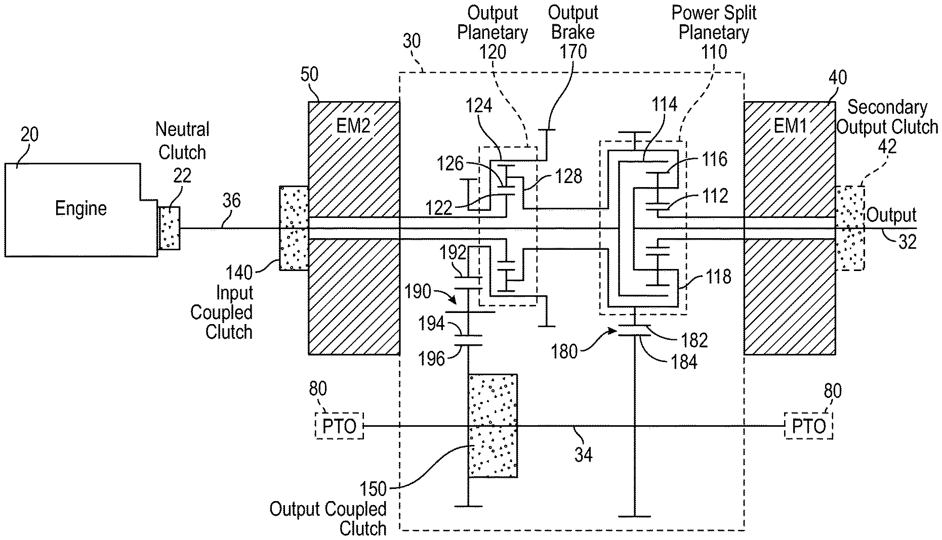
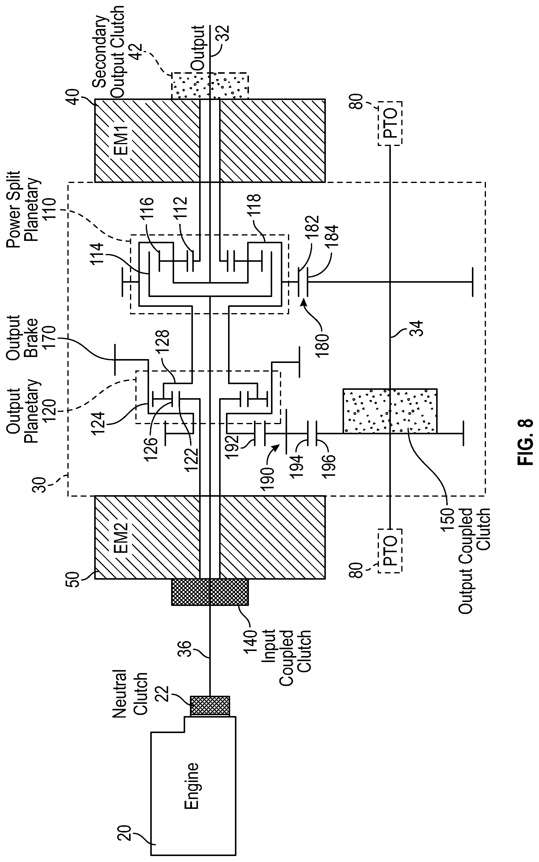
According to the exemplary embodiment shown in FIG. 2, a drive system for a vehicle, shown as drive system 100, includes engine 20, transmission 30, first electromagnetic device 40, and second electromagnetic device 50. Transmission 30 may include first electromagnetic device 40 and second electromagnetic device 50. As shown in FIG. 2, transmission 30 includes a first power transmission device or gear set, shown as power split planetary 110, and a second power transmission device or gear set, shown as output planetary 120. In one embodiment, power split planetary 110 and output planetary 120 are positioned outside of (e.g., on either side of, sandwiching, not between, etc.) first electromagnetic device 40 and second electromagnetic device 50. As shown in FIG. 2, one or both of power split planetary 110 and output planetary 120 are disposed between (e.g., sandwiched by, etc.) first electromagnetic device 40 and second electromagnetic device 50.
Referring to the exemplary embodiment shown in FIG. 2, power split planetary 110 is a planetary gear set that includes a sun gear 112, a ring gear 114, and a plurality of planetary gears 116. The plurality of planetary gears 116 couple sun gear 112 to ring gear 114, according to an exemplary embodiment. As shown in FIG. 2, a carrier 118 rotationally supports the plurality of planetary gears 116. In one embodiment, first electromagnetic device 40 is directly coupled to sun gear 112 such that power split planetary 110 is coupled to first electromagnetic device 40. By way of example, first electromagnetic device 40 may include or be coupled to a shaft (e.g., a first shaft, an input shaft, an output shaft, etc.) directly coupled to sun gear 112.
Referring still to the exemplary embodiment shown in FIG. 2, output planetary 120 is a planetary gear set that includes a sun gear 122, a ring gear 124, and a plurality of planetary gears 126. The plurality of planetary gears 126 couple sun gear 122 to ring gear 124, according to an exemplary embodiment. As shown in FIG. 2, a carrier 128 rotationally supports the plurality of planetary gears 126. In one embodiment, second electromagnetic device 50 is directly coupled to sun gear 122 such that output planetary 120 is coupled to second electromagnetic device 50. By way of example, second electromagnetic device 50 may include or be coupled to a shaft (e.g., a second shaft, an input shaft, an output shaft, etc.) directly coupled to sun gear 122. Carrier 118 is directly coupled to carrier 128, thereby coupling power split planetary 110 to output planetary 120, according to the exemplary embodiment shown in FIG. 2. In one embodiment, directly coupling carrier 118 to carrier 128 synchronizes the rotational speeds of carrier 118 and carrier 128.
Carrier 118 is directly rotationally coupled to an output with a shaft, shown as output shaft 32, according to the exemplary embodiment shown in FIG. 2. Output shaft 32 may be coupled to at least one of rear axle driveshaft 76 and front axle driveshaft 66. By way of example, output shaft 32 may be coupled to a transfer case and/or rear axle driveshaft 76 where transmission 30 is installed in place of a traditional, mechanical, straight-thru transmission. In another embodiment, the output is a PTO output, and output shaft 32 is coupled thereto. A clutch assembly may be engaged and disengaged to selectively couple at least one of front axle driveshaft 66, a transfer case, and rear axle driveshaft 76 to output shaft 32 of transmission 30 (e.g., to facilitate operation of a vehicle in a rear-wheel-drive mode, an all-wheel-drive mode, a four-wheel-drive mode, a front-wheel-drive mode, etc.). As shown in FIG. 2, the transmission 30 includes an auxiliary shaft, shown as jack shaft 34. In some embodiments, jack shaft 34 is offset (e.g., radially offset) from first electromagnetic device 40, second electromagnetic machine 50, power split planetary 110, and/or output planetary 120. As shown in FIG. 2, transmission 30 includes a shaft, shown as connecting shaft 36. A clutch, shown as neutral clutch 22 is positioned to selectively couple engine 20 to connecting shaft 36. Neutral clutch 22 may be a component of engine 20 or transmission 30 or a separate component. According to an exemplary embodiment, neutral clutch 22 and connecting shaft 36 directly couple engine 20 to power split planetary 110. In one embodiment, neutral clutch 22 and connecting shaft 36 directly couple engine 20 with ring gear 114 of power split planetary 110. According to an exemplary embodiment, power split planetary 110 is at least one of directly coupled to and directly powers a power takeoff ("PTO") (e.g., a live PTO, etc.). By way of example, ring gear 114 and/or carrier 118 of power split planetary 110 may be at least one of directly coupled to and directly power the PTO. According to an alternative embodiment, neutral clutch 22 is omitted, and connecting shaft 36 is directly coupled to engine 20.
As shown in FIG. 2, transmission 30 includes a first clutch, shown as input coupled clutch 140. Input coupled clutch 140 is positioned to selectively couple second electromagnetic device 50 with engine 20, according to an exemplary embodiment. Input coupled clutch 140 may thereby selectively couple engine 20 to output planetary 120. As shown in FIG. 2, connecting shaft 36 extends from neutral clutch 22, through input coupled clutch 140 and second electromagnetic device 50, and through output planetary 120 to power split planetary 110. Input coupled clutch 140 may selectively couple second electromagnetic device 50 with connecting shaft 36. Accordingly, input coupled clutch 140 may selectively couple connecting shaft 36 to sun gear 122 of output planetary 120. According to an exemplary embodiment, first electromagnetic device 40 and second electromagnetic device 50 (e.g., input/output shafts thereof, etc.) are aligned (e.g., radially aligned, etc.) with power split planetary 110, output planetary 120, connecting shaft 36, and/or output shaft 32 (e.g., centerlines thereof are aligned, to thereby form a straight-thru or inline transmission arrangement, etc.).
Jack shaft 34 is rotationally coupled to carrier 118 of power split planetary 110 and thereby to output shaft 32. According to the exemplary embodiment shown in FIG. 2, transmission 30 further includes a second clutch, shown as output coupled clutch 150. Output coupled clutch 150 is positioned to selectively couple jackshaft 34 to ring gear 124 of output planetary 120. In some embodiments, jack shaft 34 is rotationally coupled (e.g., selectively rotationally coupled, etc.) to one or more outputs, shown as PTO outputs 80 (e.g., to drive one or more hydraulic pumps, to power one or more hydraulic systems, to power one or more electrical power generation systems, to power one or more pneumatic systems, etc.). In other embodiments, the one or more outputs are used to power (e.g., drive, etc.) a vehicle with which transmission 30 is associated.
Transmission 30 may further include a third clutch, shown in FIG. 2 as secondary output clutch 42. In other embodiments, secondary output clutch 42 is omitted. Secondary output clutch 42 is positioned to selectively couple first electromagnetic device 40 with output shaft 32, according to an exemplary embodiment. Secondary output clutch 42 may thereby selectively couple output shaft 32 and carrier 118 to sun gear 112 of power split planetary 110. As shown in FIG. 2, output shaft 32 extends from power split planetary 110, through first electromagnetic device 40, and out through secondary output clutch 42. In other embodiments, secondary output clutch 42 is omitted.
In some embodiments, neutral clutch 22 is biased into an engaged position (e.g., with a spring, etc.) and selectively disengaged (e.g., with application of pressurized hydraulic fluid, etc.). In some embodiments, input coupled clutch 140 is biased into a disengaged position (e.g., with a spring, etc.) and selectively engaged (e.g., with application of pressurized hydraulic fluid, etc.). In some embodiments, output coupled clutch 150 is biased into a disengaged position (e.g., with a spring, etc.) and selectively engaged (e.g., with application of pressurized hydraulic fluid, etc.). In some embodiments, secondary output clutch 42 is biased into a disengaged position (e.g., with a spring, etc.) and selectively engaged (e.g., with application of pressurized hydraulic fluid, etc.). In other embodiments, one or more of neutral clutch 22, input coupled clutch 140, output coupled clutch 150, and secondary output clutch 42 are hydraulically-biased and spring released.
Referring again to the exemplary embodiment shown in FIG. 2, transmission 30 includes a brake, shown as output brake 170. Output brake 170 is positioned to selectively inhibit the movement of at least a portion of output planetary 120 (e.g., ring gear 124, etc.), according to an exemplary embodiment. In one embodiment, output brake 170 is biased into a disengaged position (e.g., with a spring, etc.) and selectively engaged (e.g., with application of pressurized hydraulic fluid, etc.). In other embodiments, output brake 170 is hydraulically-biased and spring released. In still other embodiments, the components of transmission 30 are still otherwise engaged and disengaged (e.g., pneumatically, etc.). By way of example, output brake 170 and output coupled clutch 150 may be engaged simultaneously, providing a driveline brake such that rotational movement of at least one of output planetary 120 (e.g., ring gear 124, etc.), power split planetary 110 (e.g., carrier 118, etc.), jack shaft 34, and output shaft 32 are selectively limited.
As shown in FIG. 2, transmission 30 includes a gear set 180 that couples carrier 118 and carrier 128 to jack shaft 34. In one embodiment, gear set 180 includes a first gear, shown as gear 182, in meshing engagement with a second gear, shown as gear 184. As shown in FIG. 2, gear 182 is rotatably coupled to carrier 118 and carrier 128. By way of example, gear 182 may be fixed to a component (e.g., shaft, tube, etc.) that couples carrier 118 and carrier 128. As shown in FIG. 2, gear 184 is rotatably coupled to jack shaft 34. By way of example, gear 184 may be fixed directly to the jack shaft 34.
According to an exemplary embodiment, transmission 30 includes a gear set, shown as gear set 190, that couples output planetary 120 to jack shaft 34. As shown in FIG. 2, gear set 190 includes a first gear, shown as gear 192, coupled to ring gear 124 of output planetary 120. Gear 192 is in meshing engagement with a second gear, shown as gear 194, according to an exemplary embodiment. As shown in FIG. 2, gear 194 is coupled to a third gear, shown as gear 196. Gear 194 may reverse the rotation direction of an output provided by gear 192 (e.g., gear 194 may facilitate rotating jack shaft 34 in the same direction as that of gear 192, etc.). In other embodiments, gear 192 is directly coupled with gear 196. By way of example, gear set 190 may not include gear 194, and gear 192 may be directly coupled to (e.g., in meshing engagement with, etc.) gear 196. As shown in FIG. 2, output coupled clutch 150 is positioned to selectively couple gear 196 with output shaft 32 when engaged. With output coupled clutch 150 disengaged, relative movement (e.g., rotation, etc.) may occur between gear 196 and jack shaft 34. By way of example, output coupled clutch 150 may be engaged to couple ring gear 124 to jack shaft 34. Output brake 170 is positioned to selectively limit the movement of gear 192 when engaged to thereby also limit the movement of ring gear 124, gear 194, and gear 196.
According to the exemplary embodiment shown in FIG. 3, a control system 200 for a vehicle (e.g., vehicle 10, etc.) includes a controller 210. In one embodiment, controller 210 is configured to selectively engage, selectively disengage, or otherwise communicate with components of the vehicle according to various modes of operation. As shown in FIG. 3, controller 210 is coupled to engine 20. In one embodiment, controller 210 is configured to selectively engage engine 20 (e.g., interface with a throttle thereof, etc.) such that an output of engine 20 rotates at a target rate. Controller 210 is coupled to first electromagnetic device 40 and second electromagnetic device 50, according to an exemplary embodiment, and may send and receive signals therewith. By way of example, controller 210 may send command signals relating to at least one of a target mode of operation, a target rotational speed, and a target rotation direction for first electromagnetic device 40 and second electromagnetic device 50. As shown in FIG. 3, first electromagnetic device 40 and second electromagnetic device 50 are electrically coupled (e.g., by an electrical power transmission system, etc.). By way of example, power generated by first electromagnetic device 40 may be utilized by second electromagnetic device 50 (e.g., to provide an output torque as a motor, etc.), or power generated by second electromagnetic device 50 may be utilized by first electromagnetic device 40 (e.g., to provide an output torque as a motor, etc.). Controller 210 is configured to selectively engage and selectively disengage neutral clutch 22, secondary output clutch 42, input coupled clutch 140, output coupled clutch 150, and output brake 170 directly or by interacting with another component (e.g., a pump, a valve, a solenoid, a motor, etc.).
According to an exemplary embodiment, the drive system 100 includes an energy storage device (e.g., a battery, etc.). In such embodiments, the battery may be charged and recharged by an electromagnetic device that is generating power. The battery may supply the electromagnetic device that is motoring the vehicle to propel the vehicle. In some embodiments, the battery may always be utilized as part of the drive system 100. In other embodiments, the battery may be used only when excess generated power must be stored or excess power is required to motor the vehicle.
According to alternative embodiments, drive system 100 may be configured to operate with first electromagnetic device 40 and second electromagnetic device 50, and no additional sources of electrical power. Additional sources of electrical power include, for example, a battery and other energy storage devices. Without an energy storage device, first electromagnetic device 40 and second electromagnetic device 50 may operate in power balance. One of the electromagnetic devices may provide all of the electrical power required by the other electromagnetic device (as well as the electrical power required to offset power losses). First electromagnetic device 40 and second electromagnetic device 50 may operate without doing either of (a) providing electrical power to an energy storage device or (b) consuming electrical power from an energy storage device. Thus, the sum of the electrical power produced or consumed by first electromagnetic device 40, the electrical power produced or consumed by second electromagnetic device 50, and electrical power losses may be zero. According to the embodiment of FIGS. 1-3, two electromagnetic devices are shown. In other embodiments, the system includes three or more electromagnetic devices.
According to the exemplary embodiment shown in FIG. 3, control system 200 includes a user interface 220 that is coupled to controller 210. In one embodiment, user interface 220 includes a display and an operator input. The display may be configured to display a graphical user interface, an image, an icon, or still other information. In one embodiment, the display includes a graphical user interface configured to provide general information about the vehicle (e.g., vehicle speed, fuel level, warning lights, etc.). The graphical user interface may be configured to also display a current mode of operation, various potential modes of operation, or still other information relating to transmission 30 and/or drive system 100. By way of example, the graphical user interface may be configured to provide specific information regarding the operation of drive system 100 (e.g., whether neutral clutch 22, secondary output clutch 42, input coupled clutch 140, output coupled clutch 150, and/or output brake 170 are engaged or disengaged, a fault condition where at least one of neutral clutch 22, secondary output clutch 42, input coupled clutch 140, output coupled clutch 150, and/or output brake 170 fail to engage or disengage in response to a command signal, etc.).
The operator input may be used by an operator to provide commands to at least one of engine 20, transmission 30, first electromagnetic device 40, second electromagnetic device 50, and drive system 100 or still another component of the vehicle. The operator input may include one or more buttons, knobs, touchscreens, switches, levers, or handles. In one embodiment, an operator may press a button to change the mode of operation for at least one of transmission 30, and drive system 100, and the vehicle. The operator may be able to manually control some or all aspects of the operation of transmission 30 using the display and the operator input. It should be understood that any type of display or input controls may be implemented with the systems and methods described herein.
Controller 210 may be implemented as a general-purpose processor, an application specific integrated circuit (ASIC), one or more field programmable gate arrays (FPGAs), a digital-signal-processor (DSP), circuits containing one or more processing components, circuitry for supporting a microprocessor, a group of processing components, or other suitable electronic processing components. According to the exemplary embodiment shown in FIG. 3, controller 210 includes a processing circuit 212 and a memory 214. Processing circuit 212 may include an ASIC, one or more FPGAs, a DSP, circuits containing one or more processing components, circuitry for supporting a microprocessor, a group of processing components, or other suitable electronic processing components. In some embodiments, processing circuit 212 is configured to execute computer code stored in memory 214 to facilitate the activities described herein. Memory 214 may be any volatile or non-volatile computer-readable storage medium capable of storing data or computer code relating to the activities described herein. According to an exemplary embodiment, memory 214 includes computer code modules (e.g., executable code, object code, source code, script code, machine code, etc.) configured for execution by processing circuit 212. Memory 214 includes various actuation profiles corresponding to modes of operation (e.g., for transmission 30, for drive system 100, for a vehicle, etc.), according to an exemplary embodiment. In some embodiments, controller 210 may represent a collection of processing devices (e.g., servers, data centers, etc.). In such cases, processing circuit 212 represents the collective processors of the devices, and memory 214 represents the collective storage devices of the devices.
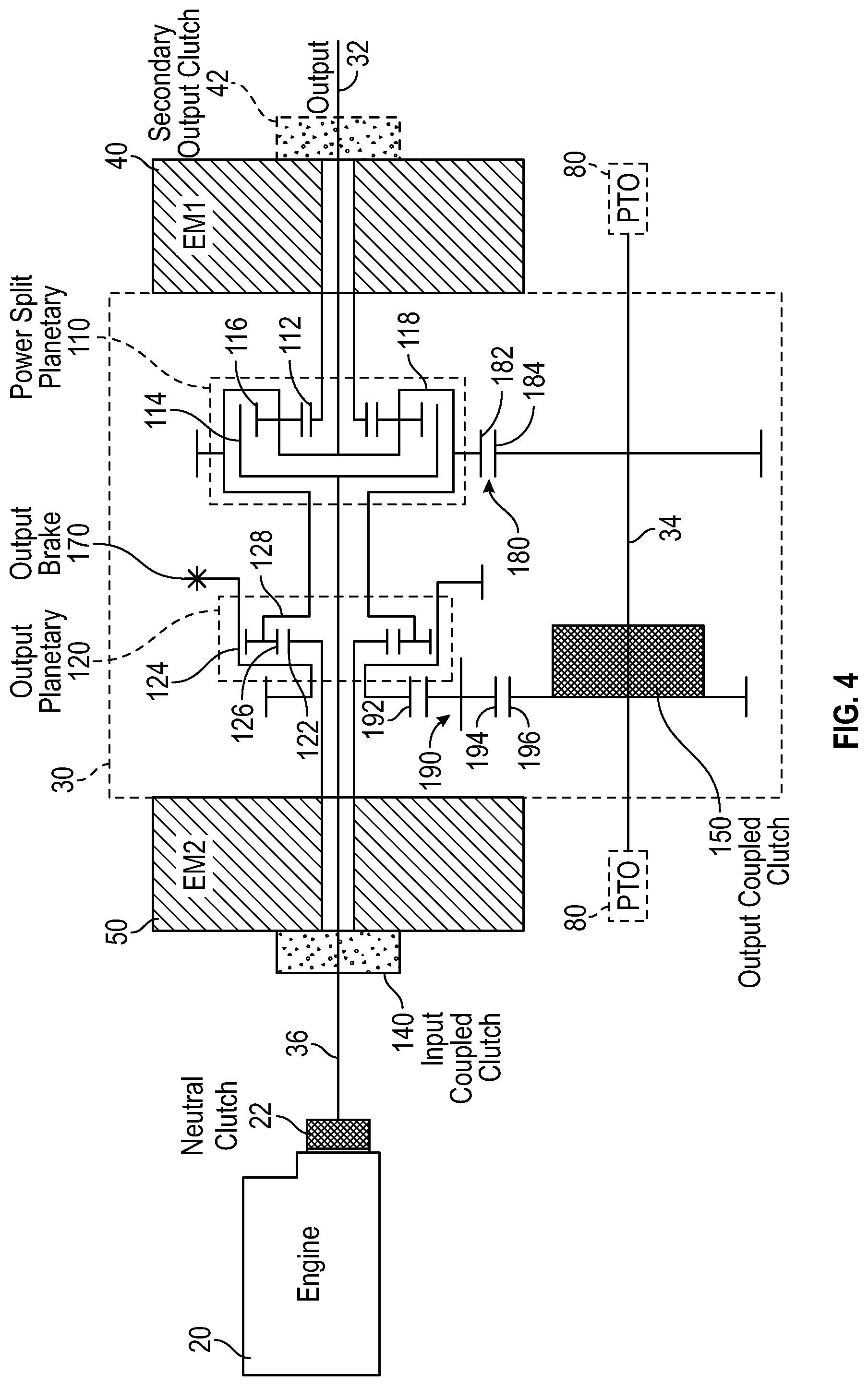
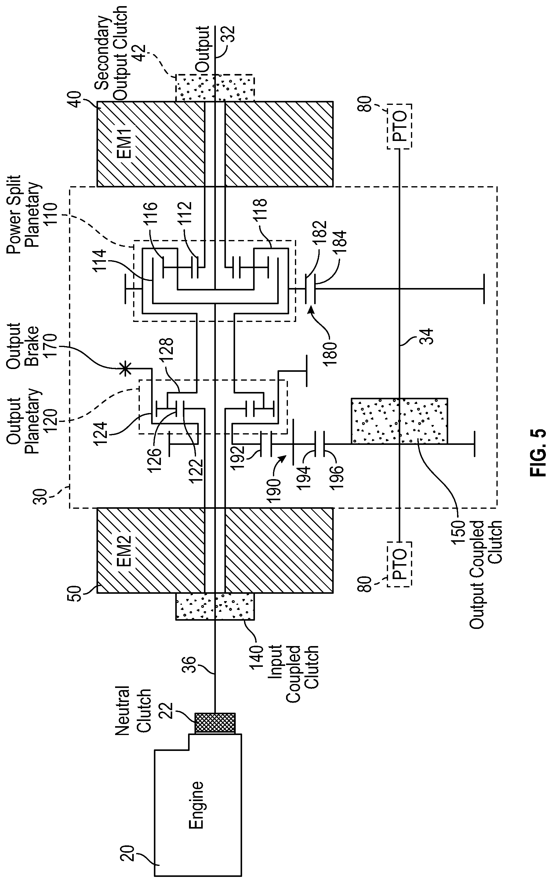
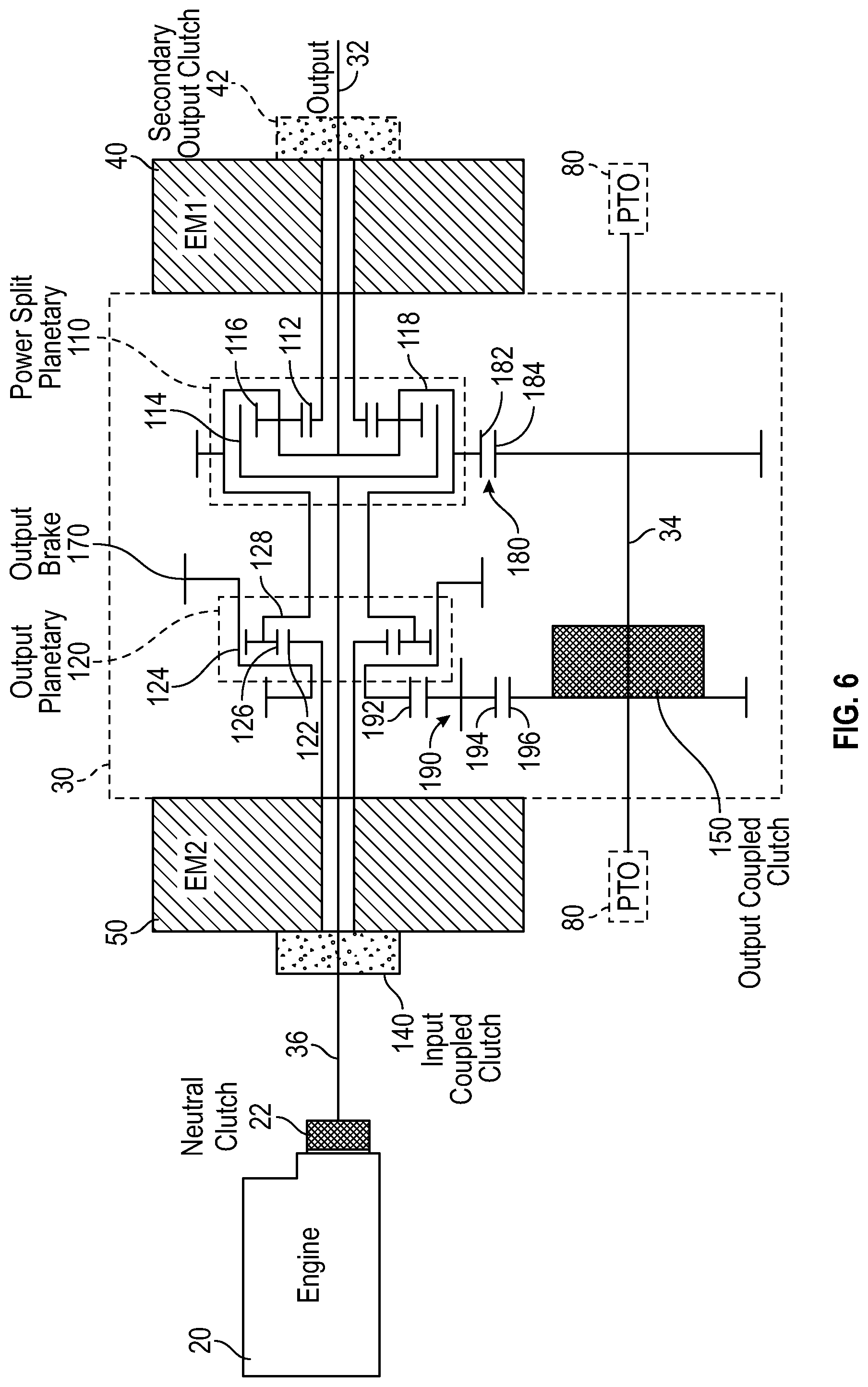
Referring next to the exemplary embodiments shown in FIGS. 4-12, transmission 30 is configured to operate according to a plurality of modes of operation. Various modes of operation for transmission 30 are identified below in Table 1. In other embodiments, a vehicle having transmission 30 is configured to operate according to the various modes of operation shown in FIGS. 4-12 and identified below in Table 1.
TABLE-US-00001 TABLE 1 Output Input Neutral Coupled Output Coupled Mode of Clutch Clutch Brake Clutch Operation 22 150 170 140 Mid Speed X X Reverse Low Speed X X Reverse Power X X Generation Neutral/Vehicle X X X Start Low Range X X Mid Range X X Shift X X X High Range X X
As shown in Table 1, an "X" represents a component of drive system 100 (e.g., output brake 170, input coupled clutch 140, etc.) that is engaged or closed during the respective modes of operation. Secondary output clutch 42 is disengaged in each of the modes shown in Table 1.
In each of the modes shown in Table 1 and FIGS. 4-12, neutral clutch 22 is engaged. When engaged, neutral clutch 22 couples engine 20 to transmission 30. When disengaged, neutral clutch 22 decouples engine 20 from transmission 30. Accordingly, neutral clutch 22 may be used to isolate engine 20 from transmission 30. Neutral clutch 22 may facilitate maintenance or towing of vehicle 10. Further, with neutral clutch 22 disengaged, electromagnetic device 40 and/or electromagnetic device 50 may be used to drive output shaft 32 and/or jack shaft 34 (e.g., to drive one or more PTO outputs 80) independent of engine 20 (e.g., without engine 20 running).
Throughout each of the modes shown in Table 1 and FIGS. 4-12, secondary output clutch 42 is disengaged. When engaged, secondary output clutch 42 limits rotation of output shaft 32 and carrier 118 relative to sun gear 112, thereby preventing rotation of the planetary gears 116 about central axes thereof. Accordingly, secondary output clutch 42 limits the rotation of ring gear 114 relative relative to carrier 118, such that rotation of connecting shaft 36 causes a corresponding rotation of output shaft 32 and electromagnetic device 40. According to an exemplary embodiment, an energy flow path with only the neutral clutch 22 and the secondary output clutch 42 engaged includes: engine 20 providing a rotational mechanical energy input to connecting shaft 36 through the neutral clutch 22; connecting shaft 36 conveying the rotational mechanical energy to ring gear 114; ring gear 114 conveying the rotational mechanical energy to the plurality of planetary gears 116; planetary gears 116 causing rotation of carrier 118 and sun gear 112 (e.g., planetary gears 116 may not rotate relative to carrier 118 or sun gear 112 because of the coupling caused by secondary output clutch 42, etc.); sun gear 112 driving first electromagnetic device 40 such that it operates as a generator (e.g., generates electrical energy, etc.); and carrier 118 driving the output shaft 32. With secondary output clutch 42 engaged, ring gear 124 and sun gear 122 may rotate freely such that second electromagnetic device 50 may rotate independently of engine 20.
As shown in FIGS. 4 and 5, transmission 30 is selectively reconfigured into neutral/startup modes. The neutral/startup mode may provide a true neutral for transmission 30. In one embodiment, at least one of first electromagnetic device 40 and second electromagnetic device 50 include and/or are coupled to an energy storage device (e.g., a capacitor, a battery, etc.) configured to store energy (e.g., electrical energy, chemical energy, etc.) associated with drive system 100. In one embodiment, rotation of first electromagnetic device 40 rotates connecting shaft 36 to start engine 20 (e.g., with neutral clutch 22, output coupled clutch 150, and output brake 170 engaged, etc.). In another embodiment, rotation of second electromagnetic device 50 rotates connecting shaft 36 to start engine 20 (e.g., with neutral clutch 22 and input coupled clutch 140 engaged, etc.). First electromagnetic device 40 or second electromagnetic device 50 may be configured to use the stored energy to start engine 20 by providing a rotational mechanical energy input (e.g., a torque, etc.) to engine 20 through connecting shaft 36.
In an alternative embodiment, engine 20 includes a traditional starting mechanism (e.g., a starter motor, etc.) configured to start engine 20 (e.g., in response to a vehicle start request, in response to an engine start request, etc.). The vehicle start request and/or the engine start request may include a directive to turn the engine "on" from an "off" state. The vehicle may include at least one of a pushbutton, a graphical user interface, an ignition, and another device with which a user interacts to provide or trigger the vehicle start request and/or the engine start request. Engine 20 may provide a rotational mechanical energy input to at least one of first electromagnetic device 40 and/or second electromagnetic device 50. First electromagnetic device 40 and second electromagnetic device 50 may be brought up to a threshold (e.g., a threshold speed, a threshold speed for a target period of time, a threshold power generation, a threshold power generation for a target period of time, etc.) that establishes a requisite DC bus voltage for controlling first electromagnetic device 40 and/or second electromagnetic device 50. Both first electromagnetic device 40 and second electromagnetic device 50 may thereafter be activated and controlled within and/or to desired states. The power electronics of control system 200 that control the motor-to-motor functions may be brought online during the neutral/startup mode.
As shown in FIG. 4 and Table 1, neutral clutch 22, output coupled clutch 150, and output brake 170 are engaged when transmission 30 is configured in the neutral/startup mode. According to an exemplary embodiment, engaging neutral clutch 22, output brake 170, and output coupled clutch 150 selectively limits the rotational movement of portions of both power split planetary 110 and output planetary 120. By way of example, engaging output brake 170 may inhibit the rotational movement of ring gear 124, gear 192, gear 194, and gear 196 such that each remains rotationally fixed. Engaging output coupled clutch 150 may inhibit rotational movement of jack shaft 34 such that jack shaft 34 remains rotationally fixed (e.g., since gear 196 is fixed and output coupled clutch 150 is engaged, etc.). With jack shaft 34 rotationally fixed, gear set 180 and carrier 118 become rotationally fixed, thereby isolating output shaft 32 from engine 20, first electromagnetic device 40, and second electromagnetic device 50 in the neutral/startup mode. Such isolation may substantially eliminate a forward lurch potential of the vehicle during startup (e.g., transmission 30 does not provide an output torque to tires 62 and/or tires 72, etc.). Alternatively, as shown in FIG. 5, output coupled clutch 150 may be disengaged (e.g., before startup, during startup, after startup, etc.). However, disengaging output coupled clutch 150 may not prevent rotation of the jack shaft 34 and thereby output shaft 32.
According to an exemplary embodiment, an energy flow path in the neutral/startup mode includes: first electromagnetic device 40 providing a rotational mechanical energy input to sun gear 112 that is received by the plurality of planetary gears 116; the plurality of planetary gears 116 rotating about central axes thereof (e.g., planetary gears 116 may not rotate about sun gear 112 because carrier 118 may be rotationally fixed, etc.); the plurality of planetary gears 116 conveying the rotational mechanical energy to ring gear 114; ring gear 114 transferring the rotational mechanical energy to the neutral clutch 22 through the connecting shaft 36 such that the rotational mechanical energy provided by first electromagnetic device 40 starts engine 20.
An alternative energy flow path in the neutral/startup mode may include starting engine 20 with a traditional starting mechanism, engine 20 providing a rotational mechanical energy input to ring gear 114 that is received by the plurality of planetary gears 116; the plurality of planetary gears 116 rotating about central axes thereof (e.g., planetary gears 116 may or may not rotate about sun gear 112 because carrier 118 may or may not be rotationally fixed, etc.); the plurality of planetary gears 116 conveying the rotational mechanical energy to sun gear 112; and sun gear 112 conveying the rotational mechanical energy to first electromagnetic device 40 to bring first electromagnetic device 40 up to the threshold for establishing a requisite DC bus voltage and controlling first electromagnetic device 40 and/or second electromagnetic device 50 in a desired state. By way of example, the neutral/startup mode may be used to start engine 20, establish a requisite DC bus voltage, or otherwise export power without relying on controller 210 to engage first electromagnetic device 40 and/or second electromagnetic device 50. Transmission 30 may provide increased export power potential relative to traditional transmission systems.
As shown in FIG. 6, transmission 30 is selectively reconfigured into a low range mode of operation such that transmission 30 allows for a low output speed operation with a high output torque (e.g., in a forward direction of travel, etc.). The low range mode increases a vehicle's gradability (e.g., facilitates the vehicle maintaining speed on a grade, etc.). In one embodiment, engine 20 provides a rotational mechanical energy input to transmission 30 such that first electromagnetic device 40 generates electrical power and second electromagnetic device 50 uses the generated electrical power to provide a rotational mechanical energy output. As such, at least one of engine 20 and second electromagnetic device 50 provide a rotational mechanical energy input to drive at least one of tires 62 and tires 72. In an alternative embodiment, first electromagnetic device 40 operates as a motor and second electromagnetic device 50 operates as a generator when transmission 30 is configured in the low range forward mode. In still another alternative embodiment, both first electromagnetic device 40 and second electromagnetic device 50 operate as a generator in the low range forward mode. In yet another embodiment, transmission 30 is not selectively reconfigurable into the low range mode of operation. In one such embodiment, transmission 30 does not include jack shaft 34, does not include gear set 190 (e.g., gear 192, gear 194, gear 196, etc.), and does not include output coupled clutch 150. Transmission 30 may additionally or alternatively not include gear set 180 in embodiments where transmission 30 is not selectively reconfigurable into the low range mode of operation.
As shown in FIG. 6 and Table 1, neutral clutch 22 and output coupled clutch 150 are engaged when transmission 30 is configured in the low range mode. As shown in FIG. 6, output coupled clutch 150 couples gear set 190 to jack shaft 34. Accordingly, when engine 20 provides a rotational mechanical energy input to transmission 30, at least one of engine 20 and second electromagnetic device 50 drive output shaft 32 through the interaction of connecting shaft 36 and jack shaft 34 with power split planetary 110, respectively. According to the exemplary embodiment shown in FIG. 6, an energy flow path for the low range includes: engine 20 providing a rotational mechanical energy input to connecting shaft 36 through the neutral clutch 22; connecting shaft 36 conveying the rotational mechanical energy to ring gear 114; ring gear 114 causing the plurality of planetary gears 116 to rotate about central axes thereof, as well as about sun gear 112 such that carrier 118 and output shaft 32 rotate; and the rotation of the plurality of planetary gears 116 about a central axis causing a rotation of sun gear 112, thus driving first electromagnetic device 40 such that it operates as a generator (e.g., generates electrical energy, etc.).
Referring still to FIG. 6, the rotation of carrier 118 drives both carrier 128 and gear set 180. Carrier 128 drives the plurality of planetary gears 126 to rotate about sun gear 122 and about central axes thereof. In one embodiment, second electromagnetic device 50 receives electrical energy generated by first electromagnetic device 40. Accordingly, second electromagnetic device 50 operates as a motor, providing a rotational mechanical energy input to sun gear 122. The sun gear 122 conveys the rotational mechanical energy to the plurality of planetary gears 126 such that each further rotates about the central axis thereof. The plurality of planetary gears 126 drive ring gear 124, and the rotation of ring gear 124 drives gear set 190. According to the exemplary embodiment shown in FIG. 6, gear set 180 and gear set 190 transfer a torque to and from jack shaft 34 with output coupled clutch 150 engaged. As such, engine 20 and second electromagnetic device 50 move a vehicle at a low speed with a high output torque.
As shown in FIG. 7, transmission 30 is selectively reconfigured into a mid range mode of operation. In the mid range mode of operation, transmission 30 may facilitate a mid range output speed operation (e.g., in a forward direction of travel, etc.). The speed range associated with the mid range mode of operation may be larger than that of traditional transmissions (i.e., transmission 30 may provide increased coverage in the mid range, etc.). The mid range mode may improve low output speed torque and high output speed power. In one embodiment, engine 20 provides a rotational mechanical energy input such that first electromagnetic device 40 generates electrical power, and second electromagnetic device 50 uses the generated electrical power to provide a rotational mechanical energy output. Second electromagnetic device 50 thereby provides a rotational mechanical energy input to drive at least one of tires 62 and tires 72. In an alternative embodiment, second electromagnetic device 50 operates as a generator while first electromagnetic device 40 operates as a motor when transmission 30 is configured in the mid range mode. In still another alternative embodiment, both first electromagnetic device 40 and second electromagnetic device 50 operate as a generator in the mid range mode.
As shown in FIG. 7 and Table 1, neutral clutch 22 and output brake 170 are engaged when transmission 30 is configured in the mid range mode. As shown in FIG. 7, output brake 170 inhibits the rotation of gear set 190 (e.g., gear 192, gear 194, gear 196, etc.). Output brake 170 thereby rotationally fixes ring gear 124. In one embodiment, engaging output brake 170 substantially eliminates a power dip between output and input modes of transmission 30. According to the exemplary embodiment shown in FIG. 7, an energy flow path for the mid range forward mode includes: engine 20 providing a rotational mechanical energy input to connecting shaft 36 that is conveyed to ring gear 114; ring gear 114 driving the plurality of planetary gears 116 to rotate about central axes thereof, as well as about sun gear 112 such that both carrier 118 and sun gear 112 rotate; and the rotation of carrier 118 driving the output shaft 32.
With ring gear 124 fixed by output brake 170, second electromagnetic device 50 may operate as a motor. In one embodiment, second electromagnetic device 50 receives electrical energy generated by first electromagnetic device 40. First electromagnetic device 40 operates as a generator, removing a rotational mechanical energy from sun gear 112. The sun gear 122 conveys rotational mechanical torque from the second electromagnetic device 50 to the plurality of planetary gears 126 such that each further rotates about sun gear 122 (e.g., at an increased rotational speed, etc.). The rotation of the plurality of planetary gears 126 (e.g., effected by sun gear 122, etc.) drives carrier 128 and thereby carrier 118. Carrier 118 drives output shaft 32 at a mid range output speed and may thereby drive a vehicle at a mid range output speed.
As shown in FIG. 8, transmission 30 is selectively reconfigured into a high range mode of operation such that transmission 30 allows for a high output speed operation (e.g., in a forward direction of travel, etc.). In one embodiment, engine 20 provides a rotational mechanical energy input such that second electromagnetic device 50 generates electrical power while first electromagnetic device 40 uses the generated electrical power to provide a rotational mechanical energy output. As such, at least one of engine 20 and first electromagnetic device 40 provide rotational mechanical energy to drive at least one of tires 62 and tires 72. In an alternative embodiment, first electromagnetic device 40 operates as a generator and second electromagnetic device 50 operates as a motor when transmission 30 is configured in the high range mode.
As shown in FIG. 8 and Table 1, neutral clutch 22 and input coupled clutch 140 are engaged when transmission 30 is configured in the high range mode. As shown in FIG. 8, the engagement of input coupled clutch 140 with connecting shaft 36 rotationally couples engine 20 and second electromagnetic device 50. By way of example, engine 20 may provide a rotational mechanical energy input to connecting shaft 36 such that second electromagnetic device 50 generates electrical energy. In one embodiment, first electromagnetic device 40 receives the electrical energy generated by second electromagnetic device 50. First electromagnetic device 40 operates as a motor, providing a rotational mechanical energy input to sun gear 112 that drives the plurality of planetary gears 116 and carrier 118.
Referring still to FIG. 8, power from engine 20 is transferred to ring gear 114 and the plurality of planetary gears 116. The plurality of planetary gears 116 are driven by at least one of engine 20 (e.g., via ring gear 114, etc.) and first electromagnetic device 40 (e.g., via sun gear 112, etc.). Carrier 118 rotates, which drives output shaft 32 such that the rotational mechanical energy provided by engine 20 and first electromagnetic device 40 drives a vehicle at a high range speed.
As shown in FIG. 9, transmission 30 is selectively reconfigured into an intermediate shift mode of operation that facilitates transitioning transmission 30 (i.e., shifting, changing modes, etc.) between the mid range mode of operation and the high range mode of operation. According to the embodiment shown in FIG. 9, neutral clutch 22, input coupled clutch 140, and output brake 170 are engaged when transmission 30 is selectively reconfigured into the intermediate shift mode of operation. According to an exemplary embodiment, the intermediate shift mode provides a smooth and robust shifting strategy that functions reliably even in a wide variety of operating conditions, when using various types of oil for the components of transmission 30, and when experiencing valve nonlinearities that may be present in one or more valves of transmission 30. The intermediate shift mode may provide a zero inertia shift through and across two or more overlapping ranges (e.g., the mid range and the high range, etc.). According to the exemplary embodiment shown in FIGS. 7-9, the intermediate shift mode eliminates the need to simultaneously disengage output brake 170 and engage input coupled clutch 140 to shift from the mid range mode to the high range mode, or vice versa. The intermediate shift mode reduces jerking sensations associated with simultaneously disengaging output brake 170 and engaging input coupled clutch 140 to shift from mid range to high range, providing a smoother ride.
During operation, the intermediate shift mode may be used to shift from mid range mode to high range mode or from high range mode to mid range mode. In one embodiment, when shifting between the mid range mode and the high range mode, both input coupled clutch 140 and output brake 170 are engaged for a period of time prior to disengaging input coupled clutch 140 or output brake 170. Transmission 30 may be selectively reconfigured into the intermediate shift mode in response to one or more inputs reaching a predetermined threshold condition, the inputs including a rotational speed of second electromagnetic device 50 and a rotational speed of connecting shaft 36 and/or engine 20. One or more sensors may be positioned to monitor the rotational speed of at least one of engine 20, connecting shaft 36, a portion of second electromagnetic device 50, or still another component. A controller (e.g., controller 210, etc.) may reconfigure transmission 30 into the intermediate shift mode in response to sensing signals provided by the one or more sensors.
As shown in FIG. 10, transmission 30 is selectively reconfigured into a low speed reverse mode of operation. In one embodiment, engine 20 provides a rotational mechanical energy input to transmission 30 such that first electromagnetic device 40 generates electrical power and second electromagnetic device 50 uses the generated electrical power to provide a rotational mechanical energy input to transmission 30. As such, at least one of engine 20 and second electromagnetic device 50 provide rotational mechanical energy to drive at least one of tires 62 and tires 72 in a reverse direction (e.g., backwards, etc.). In an alternative embodiment, first electromagnetic device 40 operates as a motor and second electromagnetic device 50 operates as a generator when transmission 30 is configured in the low range reverse mode.
As shown in FIG. 10 and Table 1, neutral clutch 22 and output coupled clutch 150 are engaged when transmission 30 is configured in the low speed reverse mode. As shown in FIG. 10, the low speed reverse mode is substantially similar to the low range mode of FIG. 6 in that output coupled clutch 150 couples gear set 190 to output shaft 32. In the low speed reverse mode, second electromagnetic device 50 may provide a rotational mechanical energy input to transmission 30 in an opposite direction as compared to the low range mode of FIG. 6.
As shown in FIG. 11, transmission 30 is selectively reconfigured into a mid speed reverse mode of operation such that transmission 30 allows for a mid reverse output speed operation. In one embodiment, engine 20 provides a rotational mechanical energy input such that first electromagnetic device 40 generates electrical power, and second electromagnetic device 50 uses the generated electrical power to provide a rotational mechanical energy input to transmission 30. As such, at least one of engine 20 and second electromagnetic device 50 provides a rotational mechanical energy input to drive at least one of tires 62 and tires 72 in a reverse direction (e.g., backwards). In an alternative embodiment, second electromagnetic device 50 operates as a generator and first electromagnetic device 40 operates as a motor when transmission 30 is configured in the mid speed reverse mode. In still another alternative embodiment, both first electromagnetic device 40 and second electromagnetic device 50 operate as a generator in the mid speed reverse mode.
As shown in FIG. 11 and Table 1, neutral clutch 22 and output brake 170 are engaged when transmission 30 is configured in the mid speed reverse mode. As shown in FIG. 11, output brake 170 inhibits the rotation of gear set 190 (e.g., gear 192, gear 194, gear 196, etc.). Output brake 170 thereby rotationally fixes ring gear 124. According to the exemplary embodiment shown in FIG. 11, an energy flow path for the mid speed reverse mode includes: engine 20 providing a rotational mechanical energy input to connecting shaft 36 that is conveyed to ring gear 114; and ring gear 114 driving the plurality of planetary gears 116 to rotate about central axes thereof, as well as about sun gear 112 such that both carrier 118 and sun gear 112 rotate.
Referring still to FIG. 11, the rotation of carrier 118 drives carrier 128, which rotates the plurality of planetary gears 126 about central axes thereof, as well as about sun gear 122. With ring gear 124 fixed by output brake 170, second electromagnetic device 50 may operate as a motor. In one embodiment, second electromagnetic device 50 receives electrical energy generated by first electromagnetic device 40. Accordingly, first electromagnetic device 40 operates as a generator, removing a rotational mechanical energy from sun gear 112. Second electromagnetic device 50 receives electrical energy from first electromagnetic device 40, applying a rotational mechanical torque to sun gear 122. The sun gear 122 conveys the rotational mechanical torque to the plurality of planetary gears 126 such that each further rotates about sun gear 122 (e.g., at an increased rotational speed, etc.). The rotation of the plurality of planetary gears 126 (e.g., effected by sun gear 122, etc.) drives carrier 128 and thereby carrier 118. Carrier 118 drives output shaft 32 at a mid reverse output speed and may thereby drive a vehicle at a mid reverse output speed.
As shown in FIG. 12, transmission 30 is selectively reconfigured into a power generation mode such that rotation of connecting shaft 36 rotates first electromagnetic device 40 and second electromagnetic device 50 to generate electrical power. In one embodiment, the electrical power is stored for future use. In another embodiment, the electrical power is used to power internal devices (e.g., control system 200, components of the vehicle, etc.) and/or external devices. As shown in FIG. 12 and Table 1, neutral clutch 22 and input coupled clutch 140 are engaged when transmission 30 is configured in the power generation mode.
According to an exemplary embodiment, engine 20 provides a rotational mechanical energy input to connecting shaft 36, which drives both first electromagnetic device 40 and second electromagnetic device 50. As shown in FIG. 12, second electromagnetic device 50 is rotationally coupled to engine 20 via the engagement of input coupled clutch 140 with connecting shaft 36 such that second electromagnetic device 50 generates electrical power. According to the exemplary embodiment shown in FIG. 12, an energy flow path for the power generation mode includes: connecting shaft 36 provides rotational mechanical energy to ring gear 114 of power split planetary 110; ring gear 114 conveys the rotational mechanical energy from connecting shaft 36 to the plurality of planetary gears 116; the plurality of planetary gears 116 rotate about central axes thereof, thereby transferring rotational mechanical energy to sun gear 112; sun gear 112 provides the rotational mechanical energy from engine 20 to first electromagnetic device 40 via the shaft of first electromagnetic device 40 such that first electromagnetic device 40 generates electrical power. In some embodiments, a brake is applied to front axle 60 and/or rear axle 70 to prevent movement of the vehicle 10 in the power generation mode.
According to an alternative embodiment, engine 20 does not provide a rotational mechanical energy input to drive a vehicle. By way of example, first electromagnetic device 40, second electromagnetic device 50, and/or another device may store energy during the above mentioned modes of operation. When sufficient energy is stored (e.g., above a threshold level, etc.), at least one of first electromagnetic device 40 and second electromagnetic device 50 may provide a rotational mechanical energy output such that the vehicle is driven without an input from engine 20 (e.g., an electric mode, etc.).
Although the figures may show a specific order of method steps, the order of the steps may differ from what is depicted. Also two or more steps may be performed concurrently or with partial concurrence. Such variation will depend on the software and hardware systems chosen and on designer choice. All such variations are within the scope of the disclosure. Likewise, software implementations could be accomplished with standard programming techniques with rule-based logic and other logic to accomplish the various connection steps, processing steps, comparison steps, and decision steps.
As utilized herein, the terms "approximately," "about," "substantially," and similar terms are intended to have a broad meaning in harmony with the common and accepted usage by those of ordinary skill in the art to which the subject matter of this disclosure pertains. It should be understood by those of skill in the art who review this disclosure that these terms are intended to allow a description of certain features described and claimed without restricting the scope of these features to the precise numerical ranges provided. Accordingly, these terms should be interpreted as indicating that insubstantial or inconsequential modifications or alterations of the subject matter described and claimed are considered to be within the scope of the invention as recited in the appended claims.
It should be noted that the terms "exemplary" and "example" as used herein to describe various embodiments is intended to indicate that such embodiments are possible examples, representations, and/or illustrations of possible embodiments (and such term is not intended to connote that such embodiments are necessarily extraordinary or superlative examples).
The terms "coupled," "connected," and the like, as used herein, mean the joining of two members directly or indirectly to one another. Such joining may be stationary (e.g., permanent, etc.) or moveable (e.g., removable, releasable, etc.). Such joining may be achieved with the two members or the two members and any additional intermediate members being integrally formed as a single unitary body with one another or with the two members or the two members and any additional intermediate members being attached to one another.
References herein to the positions of elements (e.g., "top," "bottom," "above," "below," "between," etc.) are merely used to describe the orientation of various elements in the figures. It should be noted that the orientation of various elements may differ according to other exemplary embodiments, and that such variations are intended to be encompassed by the present disclosure.
Also, the term "or" is used in its inclusive sense (and not in its exclusive sense) so that when used, for example, to connect a list of elements, the term "or" means one, some, or all of the elements in the list. Conjunctive language such as the phrase "at least one of X, Y, and Z," unless specifically stated otherwise, is otherwise understood with the context as used in general to convey that an item, term, etc. may be either X, Y, Z, X and Y, X and Z, Y and Z, or X, Y, and Z (i.e., any combination of X, Y, and Z). Thus, such conjunctive language is not generally intended to imply that certain embodiments require at least one of X, at least one of Y, and at least one of Z to each be present, unless otherwise indicated.
It is important to note that the construction and arrangement of the systems as shown in the exemplary embodiments is illustrative only. Although only a few embodiments of the present disclosure have been described in detail, those skilled in the art who review this disclosure will readily appreciate that many modifications are possible (e.g., variations in sizes, dimensions, structures, shapes and proportions of the various elements, values of parameters, mounting arrangements, use of materials, colors, orientations, etc.) without materially departing from the novel teachings and advantages of the subject matter recited. For example, elements shown as integrally formed may be constructed of multiple parts or elements. It should be noted that the elements and/or assemblies of the components described herein may be constructed from any of a wide variety of materials that provide sufficient strength or durability, in any of a wide variety of colors, textures, and combinations. Accordingly, all such modifications are intended to be included within the scope of the present inventions. Other substitutions, modifications, changes, and omissions may be made in the design, operating conditions, and arrangement of the preferred and other exemplary embodiments without departing from scope of the present disclosure or from the spirit of the appended claims.
* * * * *
References
D00000
D00001
D00002
D00003
D00004
D00005
D00006
D00007
D00008
D00009
D00010
D00011
D00012

XML
uspto.report is an independent third-party trademark research tool that is not affiliated, endorsed, or sponsored by the United States Patent and Trademark Office (USPTO) or any other governmental organization. The information provided by uspto.report is based on publicly available data at the time of writing and is intended for informational purposes only.
While we strive to provide accurate and up-to-date information, we do not guarantee the accuracy, completeness, reliability, or suitability of the information displayed on this site. The use of this site is at your own risk. Any reliance you place on such information is therefore strictly at your own risk.
All official trademark data, including owner information, should be verified by visiting the official USPTO website at www.uspto.gov. This site is not intended to replace professional legal advice and should not be used as a substitute for consulting with a legal professional who is knowledgeable about trademark law.