Interactively planning a well site
Cheng , et al.
U.S. patent number 10,584,570 [Application Number 14/286,206] was granted by the patent office on 2020-03-10 for interactively planning a well site. This patent grant is currently assigned to ExxonMobil Upstream Research Company. The grantee listed for this patent is Christopher A. Alba, Yao-Chou Cheng, Doug H. Freeman, Jose J. Sequeira, Jr., Ruben D. Uribe. Invention is credited to Christopher A. Alba, Yao-Chou Cheng, Doug H. Freeman, Jose J. Sequeira, Jr., Ruben D. Uribe.


View All Diagrams
| United States Patent | 10,584,570 |
| Cheng , et al. | March 10, 2020 |
Interactively planning a well site
Abstract
A method and systems for dynamically planning a well site are provided herein. The method includes generating, via a computing system, a three-dimensional model of a hydrocarbon field including a reservoir. The method also includes determining a location for a well site based on the three-dimensional model and determining reservoir targets for the determined location and a well trajectory for each reservoir target. The method also includes adjusting the location for the well site within the three-dimensional model and dynamically adjusting the reservoir targets and the well trajectories based on the dynamic adjustment of the location for the well site. The determination and the dynamic adjustment of the location, the reservoir targets, and the well trajectories for the well site are based on specified constraints. The method further includes determining a design for the well site based on the dynamic adjustment of the location, the reservoir targets, and the well trajectories for the well site.
| Inventors: | Cheng; Yao-Chou (Houston, TX), Uribe; Ruben D. (Humble, TX), Freeman; Doug H. (Spring, TX), Alba; Christopher A. (Willis, TX), Sequeira, Jr.; Jose J. (The Woodlands, TX) | ||||||||||
|---|---|---|---|---|---|---|---|---|---|---|---|
| Applicant: |
|
||||||||||
| Assignee: | ExxonMobil Upstream Research
Company (Spring, TX) |
||||||||||
| Family ID: | 51136773 | ||||||||||
| Appl. No.: | 14/286,206 | ||||||||||
| Filed: | May 23, 2014 |
Prior Publication Data
| Document Identifier | Publication Date | |
|---|---|---|
| US 20140365192 A1 | Dec 11, 2014 | |
Related U.S. Patent Documents
| Application Number | Filing Date | Patent Number | Issue Date | ||
|---|---|---|---|---|---|
| 61833159 | Jun 10, 2013 | ||||
| Current U.S. Class: | 1/1 |
| Current CPC Class: | E21B 43/30 (20130101); E21B 41/00 (20130101) |
| Current International Class: | E21B 43/30 (20060101); E21B 41/00 (20060101) |
References Cited [Referenced By]
U.S. Patent Documents
| 4794534 | December 1988 | Millheim |
| 5468088 | November 1995 | Shoemaker et al. |
| 5708764 | January 1998 | Borrel et al. |
| 5905657 | May 1999 | Celniker |
| 5992519 | November 1999 | Ramakrishman et al. |
| 6002985 | December 1999 | Stephenson |
| 6035255 | March 2000 | Murphy et al. |
| 6044328 | March 2000 | Murphy et al. |
| 6049758 | April 2000 | Bunks et al. |
| 6070125 | May 2000 | Murphy et al. |
| 6101447 | August 2000 | Poe, Jr. |
| 6219061 | April 2001 | Lauer et al. |
| 6236942 | May 2001 | Bush |
| 6236994 | May 2001 | Swartz et al. |
| 6353677 | March 2002 | Pfister et al. |
| 6373489 | April 2002 | Lu et al. |
| 6438069 | August 2002 | Ross et al. |
| 6490528 | December 2002 | Cheng et al. |
| 6516274 | February 2003 | Cheng et al. |
| 6519568 | February 2003 | Harvey et al. |
| 6529833 | March 2003 | Fanini et al. |
| 6549854 | April 2003 | Malinverno et al. |
| 6549879 | April 2003 | Cullick et al. |
| 6606101 | August 2003 | Malamud |
| 6612382 | September 2003 | King |
| 6643656 | November 2003 | Peterson |
| 6715551 | April 2004 | Curtis et al. |
| 6757613 | June 2004 | Chapman et al. |
| 6765570 | July 2004 | Cheung et al. |
| 6766254 | July 2004 | Bradford et al. |
| 6772066 | August 2004 | Cook |
| 6823266 | November 2004 | Czernuszenko et al. |
| 6826483 | November 2004 | Anderson et al. |
| 6823732 | December 2004 | Haarstad |
| 6829570 | December 2004 | Thambynayagam et al. |
| 6912467 | June 2005 | Schuette |
| 6912468 | June 2005 | Marin et al. |
| 6978210 | December 2005 | Suter et al. |
| 6980939 | December 2005 | Dhir et al. |
| 6980940 | December 2005 | Gurpinar et al. |
| 6993434 | January 2006 | Cheng et al. |
| 7003439 | February 2006 | Aldred et al. |
| 7027925 | April 2006 | Terentyev et al. |
| 7031842 | April 2006 | Musat et al. |
| 7035255 | April 2006 | Tzeng |
| 7047170 | May 2006 | Feldman et al. |
| 7050953 | May 2006 | Chiang et al. |
| 7054752 | May 2006 | Zabalza-Mezghani et al. |
| 7079953 | July 2006 | Thorne et al. |
| 7085696 | August 2006 | King |
| 7089167 | August 2006 | Poe |
| 7096172 | August 2006 | Colvin et al. |
| 7098908 | August 2006 | Acosta et al. |
| 7109717 | September 2006 | Constable |
| 7136064 | November 2006 | Zuiderveld |
| 7181380 | February 2007 | Dusterhoft et al. |
| 7200540 | April 2007 | Colvin |
| 7203342 | April 2007 | Pedersen |
| 7225078 | May 2007 | Shelley et al. |
| 7248258 | July 2007 | Acosta et al. |
| 7278496 | October 2007 | Leuchtenberg |
| 7280932 | October 2007 | Zoraster et al. |
| 7281213 | October 2007 | Callegari |
| 7283941 | October 2007 | Horowitz et al. |
| 7298376 | November 2007 | Chuter |
| 7314588 | January 2008 | Blankenship |
| 7328107 | February 2008 | Strack et al. |
| 7330791 | February 2008 | Kim et al. |
| 7337067 | February 2008 | Sanstrom |
| 7340347 | March 2008 | Shray et al. |
| 7343275 | March 2008 | Lenormand et al. |
| 7362329 | April 2008 | Zuiderveld |
| 7363866 | April 2008 | Gnedenko et al. |
| 7366616 | April 2008 | Bennett et al. |
| 7367411 | May 2008 | Leuchtenberg |
| 7395252 | July 2008 | Anderson et al. |
| 7409438 | August 2008 | McConnell et al. |
| 7412363 | August 2008 | Callegari |
| 7437358 | October 2008 | Arrouye et al. |
| 7451066 | November 2008 | Edwards et al. |
| 7458062 | November 2008 | Coulthard et al. |
| 7460957 | December 2008 | Prange et al. |
| 7478024 | January 2009 | Gurpinar et al. |
| 7512543 | March 2009 | Raghuraman et al. |
| 7519976 | April 2009 | Blevins |
| 7539625 | May 2009 | Klumpen et al. |
| 7548873 | June 2009 | Veeningen et al. |
| 7565243 | July 2009 | Kim et al. |
| 7576740 | August 2009 | Dicken |
| 7596481 | September 2009 | Zamora et al. |
| 7603264 | October 2009 | Zamora et al. |
| 7606666 | October 2009 | Repin et al. |
| 7616213 | November 2009 | Chuter |
| 7620534 | November 2009 | Pita et al. |
| 7627430 | December 2009 | Hawtin |
| 7630914 | December 2009 | Veeningen et al. |
| 7652779 | January 2010 | Wu et al. |
| 7657407 | February 2010 | Logan |
| 7657414 | February 2010 | Zamora et al. |
| 7657494 | February 2010 | Wilkinson et al. |
| 7668700 | February 2010 | Erignac et al. |
| 7672826 | March 2010 | Chen et al. |
| 7684929 | March 2010 | Prange et al. |
| 7711550 | May 2010 | Feinberg et al. |
| 7716028 | May 2010 | Montaron et al. |
| 7716029 | May 2010 | Couet et al. |
| 7725302 | May 2010 | Ayan et al. |
| 7739089 | June 2010 | Gurpinar et al. |
| 7743006 | June 2010 | Woronow et al. |
| 7752022 | July 2010 | Fornel et al. |
| 7778811 | August 2010 | Kelfoun |
| 7796468 | September 2010 | Kellogg |
| 7814989 | October 2010 | Nikolakis-Mouchas et al. |
| 7876705 | January 2011 | Gurpinar et al. |
| 7878268 | February 2011 | Chapman et al. |
| 7886285 | February 2011 | Asselin et al. |
| 7899657 | March 2011 | Martin |
| 7913190 | March 2011 | Grimaud et al. |
| 7925483 | April 2011 | Xia et al. |
| 7925695 | April 2011 | McConnell et al. |
| 7953585 | May 2011 | Gurpinar et al. |
| 7953587 | May 2011 | Bratton et al. |
| 7970545 | June 2011 | Sanstrom |
| 7986319 | July 2011 | Dommisse et al. |
| 7991600 | August 2011 | Callegari |
| 7995057 | August 2011 | Chuter |
| 8005658 | August 2011 | Tilke et al. |
| 8044602 | October 2011 | Smith |
| 8055026 | November 2011 | Pedersen |
| 8064684 | November 2011 | Ratti et al. |
| 8073664 | December 2011 | Schottle et al. |
| 8094515 | January 2012 | Miller et al. |
| 8103493 | January 2012 | Sagert et al. |
| 8145464 | March 2012 | Amegaard et al. |
| 8155942 | April 2012 | Sarma et al. |
| 8199166 | June 2012 | Repin et al. |
| 8204728 | June 2012 | Schottle et al. |
| 8249844 | August 2012 | Dale et al. |
| 8259126 | September 2012 | Chuter |
| 8280635 | October 2012 | Ella et al. |
| 8296720 | October 2012 | Coulthard et al. |
| 8301426 | October 2012 | Abasov et al. |
| 8325179 | December 2012 | Murray et al. |
| 8346695 | January 2013 | Pepper et al. |
| 8364404 | January 2013 | Legendre et al. |
| 8381815 | February 2013 | Karanikas et al. |
| 8392163 | March 2013 | Liu |
| 8427904 | April 2013 | Miller et al. |
| 8560476 | October 2013 | Anderson et al. |
| 8578000 | November 2013 | Van Wie et al. |
| 8598882 | December 2013 | Meekes |
| 8638328 | January 2014 | Lin |
| 8727017 | May 2014 | Hilliard et al. |
| 8731872 | May 2014 | Czernuszenko et al. |
| 8731873 | May 2014 | Walker et al. |
| 8731875 | May 2014 | Hilliard et al. |
| 8736600 | May 2014 | Lin et al. |
| 8751208 | June 2014 | Brouwer et al. |
| 8797319 | August 2014 | Lin |
| 8803878 | August 2014 | Andersen et al. |
| 8812334 | August 2014 | Givens et al. |
| 8849639 | September 2014 | Brown et al. |
| 8849640 | September 2014 | Holl et al. |
| 8868540 | October 2014 | Ture et al. |
| 8884964 | November 2014 | Holl et al. |
| 8931580 | January 2015 | Cheng et al. |
| 9026417 | May 2015 | Sequeira, Jr. et al. |
| 9047689 | June 2015 | Stolte et al. |
| 9123161 | September 2015 | Adair et al. |
| 2002/0049575 | April 2002 | Jalali et al. |
| 2002/0067373 | June 2002 | Roe et al. |
| 2002/0177955 | November 2002 | Jalali et al. |
| 2003/0072907 | April 2003 | Lerner et al. |
| 2003/0078794 | April 2003 | Knapp |
| 2004/0012670 | January 2004 | Zhang |
| 2004/0207652 | October 2004 | Ratti et al. |
| 2004/0268338 | December 2004 | Gurpinar et al. |
| 2005/0119959 | June 2005 | Eder |
| 2005/0120242 | June 2005 | Mayer et al. |
| 2005/0171700 | August 2005 | Dean |
| 2005/0199391 | September 2005 | Cudmore et al. |
| 2006/0085174 | April 2006 | Hemanthkumar |
| 2006/0224423 | October 2006 | Sun et al. |
| 2006/0247903 | November 2006 | Schottle |
| 2006/0265508 | November 2006 | Angel et al. |
| 2007/0076044 | April 2007 | Corley, Jr. et al. |
| 2007/0088707 | April 2007 | Durgin et al. |
| 2007/0100703 | May 2007 | Noda |
| 2007/0185696 | August 2007 | Moran et al. |
| 2007/0199721 | August 2007 | Givens et al. |
| 2007/0213935 | September 2007 | Fagnou et al. |
| 2007/0266082 | November 2007 | McConnell et al. |
| 2007/0294034 | December 2007 | Bratton et al. |
| 2008/0088621 | April 2008 | Grimaud et al. |
| 2008/0120076 | May 2008 | Thambynayagam et al. |
| 2008/0165185 | July 2008 | Smith et al. |
| 2008/0165186 | July 2008 | Lin |
| 2008/0243749 | October 2008 | Pepper et al. |
| 2008/0297510 | December 2008 | Callegari |
| 2008/0300793 | December 2008 | Tilke |
| 2008/0306803 | December 2008 | Vaal et al. |
| 2009/0027380 | January 2009 | Rajan et al. |
| 2009/0027385 | January 2009 | Smith |
| 2009/0037114 | February 2009 | Peng et al. |
| 2009/0043507 | February 2009 | Dommisse et al. |
| 2009/0056935 | March 2009 | Prange |
| 2009/0070086 | March 2009 | LeRavalec et al. |
| 2009/0089028 | April 2009 | Sagert et al. |
| 2009/0125362 | May 2009 | Reid et al. |
| 2009/0132170 | May 2009 | Krueger et al. |
| 2009/0157367 | June 2009 | Meyer et al. |
| 2009/0182541 | July 2009 | Crick et al. |
| 2009/0198447 | August 2009 | Legendre et al. |
| 2009/0205819 | August 2009 | Dale et al. |
| 2009/0222742 | September 2009 | Pelton et al. |
| 2009/0229819 | September 2009 | Repin et al. |
| 2009/0240564 | September 2009 | Boerries et al. |
| 2009/0295792 | December 2009 | Liu et al. |
| 2009/0299709 | December 2009 | Liu |
| 2009/0303233 | December 2009 | Lin et al. |
| 2009/0319243 | December 2009 | Suarez-Rivera et al. |
| 2010/0013831 | January 2010 | Gilje et al. |
| 2010/0053161 | March 2010 | Chuter |
| 2010/0132450 | June 2010 | Pomerantz et al. |
| 2010/0161292 | June 2010 | Shook et al. |
| 2010/0161300 | June 2010 | Yeten et al. |
| 2010/0169018 | July 2010 | Brooks |
| 2010/0171740 | July 2010 | Andersen et al. |
| 2010/0172209 | July 2010 | Miller et al. |
| 2010/0174489 | July 2010 | Bryant et al. |
| 2010/0179797 | July 2010 | Cullick |
| 2010/0185395 | July 2010 | Pirovolou et al. |
| 2010/0191516 | July 2010 | Benish |
| 2010/0206559 | August 2010 | Sequeira, Jr. et al. |
| 2010/0214870 | August 2010 | Pepper et al. |
| 2010/0225642 | September 2010 | Murray et al. |
| 2010/0271232 | October 2010 | Clark et al. |
| 2010/0283788 | November 2010 | Rothnemer et al. |
| 2010/0286917 | November 2010 | Hazlett et al. |
| 2010/0299125 | November 2010 | Ding et al. |
| 2010/0307742 | December 2010 | Philips et al. |
| 2011/0022435 | January 2011 | Reid et al. |
| 2011/0029293 | February 2011 | Petty et al. |
| 2011/0040533 | February 2011 | Torrens et al. |
| 2011/0040536 | February 2011 | Levitan |
| 2011/0044532 | February 2011 | Holl et al. |
| 2011/0054857 | March 2011 | Moguchaya |
| 2011/0060572 | March 2011 | Brown et al. |
| 2011/0063292 | March 2011 | Holl et al. |
| 2011/0074766 | March 2011 | Page et al. |
| 2011/0099547 | April 2011 | Banga |
| 2011/0106514 | May 2011 | Omeragic et al. |
| 2011/0107246 | May 2011 | Vik |
| 2011/0109633 | May 2011 | Sequeira, Jr. et al. |
| 2011/0112802 | May 2011 | Wilson et al. |
| 2011/0115787 | May 2011 | Kadlee |
| 2011/0126192 | May 2011 | Frost et al. |
| 2011/0153300 | June 2011 | Holl |
| 2011/0157235 | June 2011 | Fitzsimmons |
| 2011/0161133 | June 2011 | Staveley et al. |
| 2011/0168391 | July 2011 | Saleri et al. |
| 2011/0175899 | July 2011 | Bittar et al. |
| 2012/0037359 | February 2012 | Schottle |
| 2012/0137281 | May 2012 | Kleiner et al. |
| 2012/0150449 | June 2012 | Dobin |
| 2012/0166166 | June 2012 | Czernuszenko |
| 2013/0231901 | September 2013 | Lu |
| 2013/0317798 | November 2013 | Cheng et al. |
| 2014/0365192 | December 2014 | Cheng et al. |
| 2015/0049084 | February 2015 | Cheng et al. |
| 2015/0094994 | April 2015 | Sequeira, Jr. et al. |
| 2016/0003008 | January 2016 | Uribe et al. |
| 2312381 | Jun 1999 | CA | |||
| 1036341 | Nov 1998 | EP | |||
| 1230566 | Nov 2000 | EP | |||
| 2000/14574 | Mar 2000 | WO | |||
| 2003/072907 | Sep 2003 | WO | |||
| 2005/020044 | Mar 2005 | WO | |||
| 2006/029121 | Mar 2006 | WO | |||
| 2007/076044 | Jul 2007 | WO | |||
| 2007/100703 | Sep 2007 | WO | |||
| 2008/121950 | Oct 2008 | WO | |||
| 2009/032416 | Mar 2009 | WO | |||
| 2009/039422 | Mar 2009 | WO | |||
| 2009/079160 | Jun 2009 | WO | |||
| 2009/080711 | Jul 2009 | WO | |||
| 2009/148681 | Dec 2009 | WO | |||
| 2011/038221 | Mar 2011 | WO | |||
| WO 2012027020 | Mar 2012 | WO | |||
| WO-2012115690 | Aug 2012 | WO | |||
Other References
|
Cabral, B., et al (1995), "Accelerated Volume Rendering and Tomographic Reconstruction Using Texture Mapping Hardware", IEEE in Symposium on Volume Visualization, pp. 91-98, 131. cited by applicant . McCann, P., et al. (2003), "Horizontal Well Path Planning and Correction Using Optimization Techniques,"J. of Energy Resources Tech. 123, pp. 187-193. cited by applicant . Mugerin. C., et al. (2002), "Well Design Optimization: Implementation in GOCAD," 22.sup.nd Gocade Meeting, Jun. 2002. cited by applicant . Rainaud, J.F., et al. (2004), "WOG--Well Optimization by Geosteering: A Pilot Software for Cooperative Modeling on Internet," Oil & Gas Science & Tech. 59(4), pp. 427-445. cited by applicant . Reed, P., et al. (2003) "Simplifying Multiobjective Optimization Using Genetic Algorithms," Proceedings of World Water and Environmental Resources Congress, 10 pgs. cited by applicant . Udoh, E., et al. (2003), "Applications of Strategic Optimization Techniques to Development and Management of Oil and Gas Resources", 27.sup.th SPE Meeting, 16 pgs. cited by applicant . European Search Report, dated Jul. 19, 2009, EP 09150617. cited by applicant . International Search Report and Written Opinion, dated Aug. 17, 2009, PCT/US2009/049594. cited by applicant . Bharat, K, et al. (2001), "Who Links to Whom: Mining Linkage Between Web sites", Proceedings of the 2001 IEE Int 'l Conf. on Data Mining, pp. 51-58. cited by applicant . Crawfis, R., et al. (1992), "Direct Volume Visualization of Three-Dimensional Vector Fields", Proceedings of the 1992 Workshop on Volume Visualization, pp. 55-60. cited by applicant . Dhillon, S. (2008), "Managing License Incompatibilities Distributing Eclipse Application Stacks", Thesis, pp. 1-116. cited by applicant . Drebin, R., et al. (1988), "Volume Rendering", Computer Graphics, the Proceedings of 1988 SIGGRAPH Conference, vol. 22, No. 4, pp. 65-74. cited by applicant . Lorensen, W., et al., (1987), "Marching Cubes: A High-Resolution 3D Surface Construction Algorithm", Computer Graphics, The Proceeding of 1987 SIGGRAPH Conference, vol. 21, No. 4, pp. 163-169. cited by applicant . Yuen, B.B.W., et al. (2011) "Optimizing Development Well Placements Within Geological Uncertainty Utilizing Sector Models" SPE 148017. Paper prepared for presentation at the SPE Reservoir Characterization and Simulation Conference and Exhibition held in Abu Dhabi, UAE, Oct. 9-11, 2011. cited by applicant. |
Primary Examiner: Perveen; Rehana
Assistant Examiner: Crabb; Steven W
Attorney, Agent or Firm: ExxonMobil Upstream Research Company--Law Department
Parent Case Text
CROSS-REFERENCE TO RELATED APPLICATION
This application claims the benefit of U.S. Provisional Patent Application 61/833,159 filed Jun. 10, 2013 entitled INTERACTIVELY PLANNING A WELL SITE, the entirety of which is incorporated by reference herein.
Claims
What is claimed is:
1. A method for dynamically planning a well site, comprising: generating, via a computing system, a three-dimensional model of a hydrocarbon field comprising a reservoir, wherein the three-dimensional model comprises a geologic structure and a topology of the hydrocarbon field; determining a first location for a well site based on the three-dimensional model; determining a configuration for a drill center for the well site, wherein the drill center configuration is determined prior to selection of reservoir targets; determining, based on the determined drill center configuration, a first set of reservoir targets for the determined first location, wherein the number of reservoir targets in the first set of reservoir targets does not exceed the number of slots in the determined drill center configuration; determining a well trajectory for a well from each slot in the drill center for each of the first set of reservoir targets; displaying, via a user interface, the three-dimensional model comprising the first well site and first set of reservoir targets and well trajectories for each of the first set of reservoir targets; allowing a user to interactively adjust, via the user interface, the first location and select a second location for a well site based on the three-dimensional model by moving an indicator over the three-dimensional model, wherein the user interface allows the user to drag the indicator across the three-dimensional model and drop the indicator over a desired well site location on the three-dimensional model and wherein the user interface prevents the user from dragging the indicator over locations that are not suitable for a well site based on the geologic structure and topology of the hydrocarbon field; dynamically adjusting, via a computing system, the reservoir targets and the well trajectories based on the adjustment of the location for the well site to the second location wherein the dynamically adjusting comprises: automatically adjusting model parameters in a simulation that involve the reservoir targets, the well trajectories, the drill center configuration, and the location for the well site as the user changes the well site location; and automatically displaying changes to the reservoir targets and the well trajectories in the three-dimensional model in a real-time fashion as the user changes the well site location via a display device; determining whether a design for a suitable well site has been designed, wherein the determination is based at least in part on comparing the first well site location and corresponding well trajectories to the second well site location and corresponding well trajectories; evaluating the design for the suitable well site, wherein the evaluating comprises identifying one or more additional reservoir targets and determining whether one or more of the well trajectories in the design for the suitable well site can be horizontally extended to reach the one or more additional reservoir targets; displaying the suitable well site, the reservoir targets, and the well trajectories of the design; and causing one or more wells to be drilled in the hydrocarbon field based on the design for the suitable well site.
2. The method of claim 1, wherein dynamically adjusting the reservoir targets and the well trajectories for the well site based on the adjustment of the location for the well site to the second location comprises satisfying anti-collision constraints relating to existing well sites.
3. The method of claim 1, wherein dynamically adjusting the reservoir targets and the well trajectories for the well site based on the adjustment of the location for the well site to the second location comprises satisfying constraints relating to a predefined maximum horizontal distance between the location for the well site and each reservoir target.
4. The method of claim 1, comprising automatically determining or automatically adjusting the reservoir targets and the well trajectories for the well site via the computing system.
5. The method of claim 1, wherein the user interface disallows the indicator from moving over one or more locations represented by the three-dimensional model based on anti-collision constraints relating to existing well sites in the hydrocarbon field.
6. The method of claim 1, wherein the user interface disallows the indicator from moving over one or more locations represented by the three-dimensional model based on constraints relating to a predefined maximum horizontal distance between the location for the well site and each reservoir target.
7. The method of claim 1, wherein determining the design for the suitable well site comprises determining which of the first well site location and corresponding well trajectories and the second well site location and corresponding well trajectories is expected to provide a higher amount of hydrocarbons recovery from the reservoir at a lowest cost.
8. The method of claim 1, wherein the indicator of the user interface changes colors or bounces off of a location when the user attempts to drag the indicator over a location that is not suitable for a well site.
Description
FIELD OF INVENTION
The present techniques relate generally to interactively planning a well site. More specifically, the present techniques provide for the interactive planning of a well site for recovering hydrocarbons from a reservoir based on a three-dimensional model of a hydrocarbon field including the reservoir.
BACKGROUND
This section is intended to introduce various aspects of the art, which may be associated with exemplary embodiments of the present techniques. This discussion is believed to assist in providing a framework to facilitate a better understanding of particular aspects of the present techniques. Accordingly, it should be understood that this section should be read in this light, and not necessarily as admissions of prior art.
The process of planning a well site for the development of a hydrocarbon field involves several discrete decisions. Specifically, the well site locations and the reservoir targets for the available slots in the drill center are selected. In addition, the trajectory of each well within the well site is planned such that certain engineering constraints are met. Such engineering constraints may relate to environmental issues, issues regarding the safe distance around the wells, issues regarding the costs of the facilities and the drilling process for the well site, or the like. For example, engineering constraints relating to environmental issues may specify that the well site location is to avoid certain obstacles, such as pipelines, roads, buildings, hazardous areas, environmentally protected areas, and the like. In addition, engineering constraints relating to issues regarding the safe distance around the wells may specify that the well site location is to be at least a specified distance away from existing wells to avoid potential collisions. Therefore, the main objective during the planning of a well site may be to maximize the total production output by selecting a suitable well site location and suitable reservoir targets, while meeting relevant engineering constraints and minimizing costs. However, planning a well site that meets this objective is often a complex and time-consuming process.
According to current techniques, a well site is planned and built as resources become available. First, a set of potential reservoir targets is selected. Second, a well site location is chosen at an appropriate surface location so that the horizontal reach to each reservoir target does not exceed a predefined distance. Third, the drill center for the well site is designed, and a set of well trajectories starting from the slots in the drill center are designed based on well path building algorithms and engineering constraints. However, according to such techniques, the user has to manually select the reservoir targets that are reachable from the slots in the drill center. Moreover, if the drill center has to be relocated to a different well site location, some of the previously selected reservoir targets may be more than the predefined horizontal distance from the well site location and, thus, may not meet the engineering constraints. In addition, some of the previously selected reservoir targets may not meet other engineering constraints, such as constraints relating to total measured depth, dogleg severity, or the like.
U.S. Pat. No. 6,549,879 to Cullick et al. describes a method for determining well locations in a three-dimensional reservoir model while satisfying various constraints. Such constraints include minimum inter-well spacing, maximum well length, angular limits for deviated completions, and minimum distance from reservoir and fluid boundaries. In the first stage, the wells are placed assuming that the wells can only be vertical. In the second stage, the vertical wells are examined for optimized horizontal and deviated completions. This process may be used to provide an initial set of well locations and configurations.
U.S. Pat. No. 7,096,172 to Colvin et al. describes a system and method for the automatic selection of targets for well placement using two-dimensional matrices that represent a three-dimensional model of the reservoir. Specifically, a number of values in a three-dimensional model are filtered to eliminate values that are below a threshold, and a first matrix that represents a two-dimensional model of the reservoir is developed based on values in the three-dimensional model. A second matrix is then developed from the first matrix using a distance-weighted sum of the values, and target locations are selected from the second matrix based on the distance-weighted sum of the values.
U.S. Patent Application Publication No. US 2008/0300793 by Tilke et al. describes a hybrid evolutionary algorithm technique for automatically calculating well and drainage locations in a hydrocarbon field. The hybrid evolutionary algorithm technique includes planning a set of wells for a static reservoir model using an automated well planner tool, and then selecting a subset of the wells based on dynamic flow simulation using a cost function that maximizes recovery or economic benefit.
U.S. Patent Application Publication No. US 2010/0125349 by Abasov et al. describes a system and method for developing a plan for multiple wellbores with a reservoir simulator based on actual and potential reservoir performance. Connected grid cells in a gridded reservoir model that meet particular criteria are identified, and a drainable volume indicator is created for each group of connected grid cells. An adjustment value for each drainable volume is calculated, and each drainable volume that has an adjustment value up to a predetermined maximum adjustment value is designated as a completion interval grid. Contiguous completion interval grids are then connected to form one or more completion intervals.
All of the techniques described above provide for the planning of a well site. However, such techniques do not provide flexibility during the planning process but, rather, automatically plan the well site based on predefined conditions. However, in many cases, it may be desirable to provide a dynamic well site planning process that responds to user interaction.
SUMMARY
An exemplary embodiment provides a method for dynamically planning a well site. The method includes generating, via a computing system, a three-dimensional model of a hydrocarbon field including a reservoir. The method also includes determining a location for a well site based on the three-dimensional model and determining reservoir targets for the determined location and a well trajectory for each reservoir target. The method also includes dynamically adjusting the location for the well site based on the three-dimensional model and dynamically adjusting the reservoir targets and the well trajectories based on the dynamic adjustment of the location for the well site. The determination and the dynamic adjustment of the location, the reservoir targets, and the well trajectories for the well site are based on specified constraints. The method further includes determining a design for the well site based on the dynamic adjustment of the location, the reservoir targets, and the well trajectories for the well site.
Another exemplary embodiment provides a computing system for dynamically planning a well site. The computing system includes a processor and a storage medium. The storage medium includes a three-dimensional model of a hydrocarbon field including a reservoir and specified constraints for planning a well site at the hydrocarbon field. The computing system also includes a non-transitory, computer-readable medium including code configured to direct the processor to dynamically determine a location for the well site based on the three-dimensional model and the specified constraints in response to feedback from a user of the computing system, and dynamically determine reservoir targets for the well site based on the three-dimensional model and the specified constraints in response to the dynamic determination of the location for the well site. The non-transitory, computer-readable medium also includes code configured to direct the processor to dynamically determine a well trajectory for each reservoir target based on the three-dimensional model and the specified constraints, and determine a design for the well site based on the dynamic determination of the location, the reservoir targets, and the well trajectories for the well site in response to feedback from the user.
Another exemplary embodiment provides a non-transitory, computer-readable storage medium for storing computer-readable instructions. The computer-readable instructions include code configured to direct a processor to generate a three-dimensional model of a hydrocarbon field including a reservoir and display the three-dimensional model to a user via a display device. The computer-readable instructions also include code configured to direct the processor to determine a location for a well site based on the three-dimensional model in response to feedback from a user, automatically determine reservoir targets for the determined location based on a drill center of a specified configuration, and automatically determine a well trajectory for each reservoir target. The computer-readable instructions also include code configured to direct the processor to dynamically update the location for the well site based on the three-dimensional model in response to feedback from the user and automatically update the reservoir targets and the well trajectories as the location for the well site is dynamically updated. The location, the reservoir targets, and the well trajectories for the well site are determined and updated based, at least in part, on specified constraints. The computer-readable instructions further include code configured to direct the processor to determine a design for the well site based on the determination and updating of the location, the reservoir targets, and the well trajectories for the well site.
BRIEF DESCRIPTION OF THE DRAWINGS
The advantages of the present techniques are better understood by referring to the following detailed description and the attached drawings, in which:
FIG. 1 is a schematic of a hydrocarbon field including a number of potential reservoir targets for the production of hydrocarbons;
FIG. 2A is a schematic showing an exemplary configuration of a drill center for a well site;
FIG. 2B is a schematic showing another exemplary configuration of a drill center for a well site;
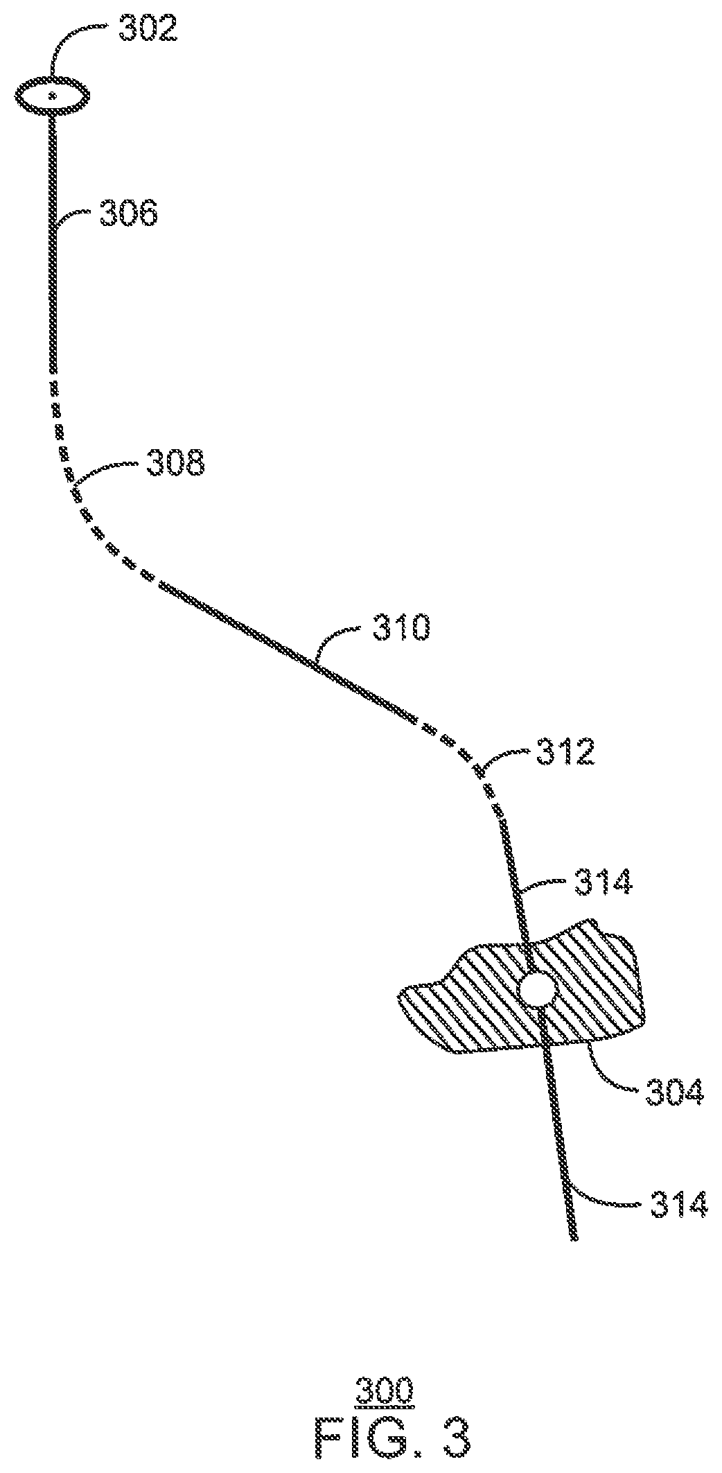
FIG. 3 is a schematic of a deviated well trajectory that may extend from a slot in the drill center to a specified reservoir target;
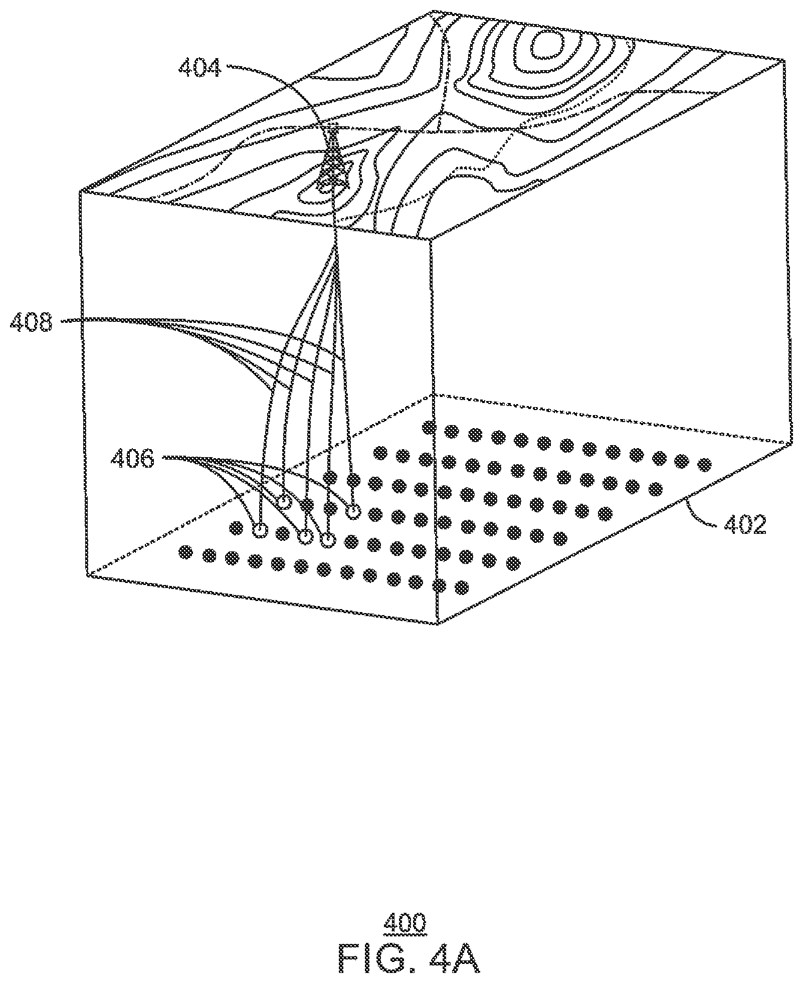
FIG. 4A is a schematic of a three-dimensional model of a hydrocarbon field including an initial well site that may be generated according to embodiments described herein;
FIG. 4B is a schematic of a three-dimensional model of the hydrocarbon field including an alternative well site that may be generated instead of the initial well site according to embodiments described herein;
FIG. 4C is a schematic of a three-dimensional model of the hydrocarbon field including a final well site that may be generated according to embodiments described herein;
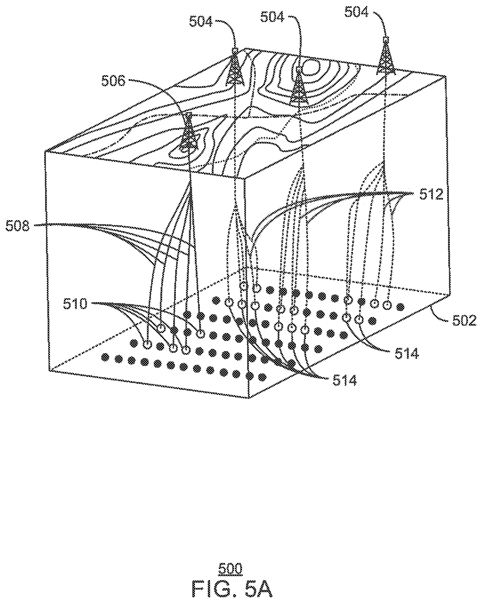
FIG. 5A is a schematic of a three-dimensional model of a hydrocarbon field including a number of existing well sties and an initial well site that may be generated according to embodiments described herein;
FIG. 5B is a schematic of a three-dimensional model of the hydrocarbon field including an alternative well site that may be generated instead of the initial well according to embodiments described herein;
FIG. 6 is a process flow diagram of a method for dynamically planning a well site for the development of a hydrocarbon field;
FIG. 7 is a generalized process flow diagram of a method for dynamically planning a well site; and
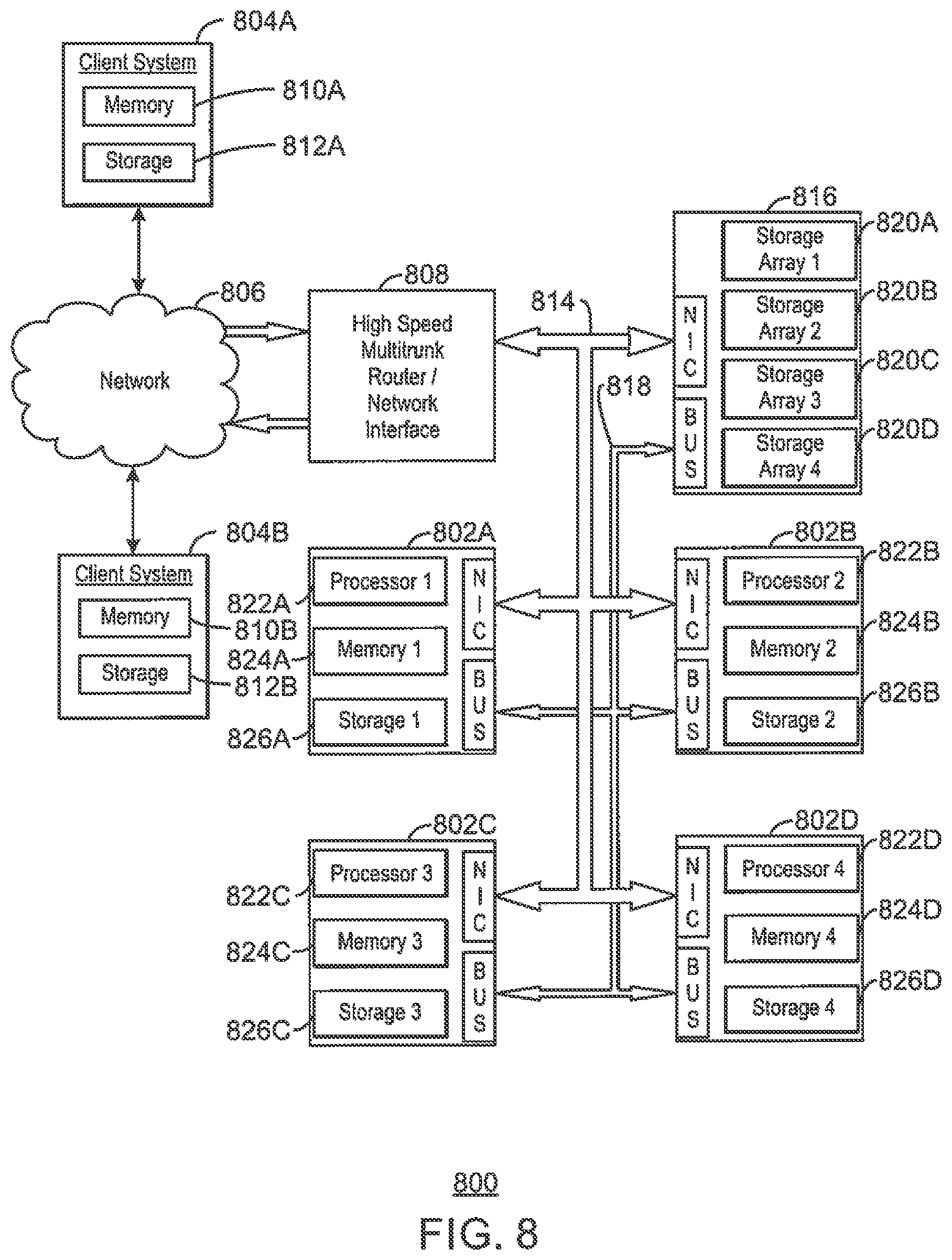
FIG. 8 is a block diagram of a cluster computing system that may be used to implement the dynamic well site planning process described herein.
DETAILED DESCRIPTION
In the following detailed description section, specific embodiments of the present techniques are described. However, to the extent that the following description is specific to a particular embodiment or a particular use of the present techniques, this is intended to be for exemplary purposes only and simply provides a description of the exemplary embodiments. Accordingly, the techniques are not limited to the specific embodiments described below, but rather, include all alternatives, modifications, and equivalents falling within the true spirit and scope of the appended claims.
At the outset, for ease of reference, certain terms used in this application and their meanings as used in this context are set forth. To the extent a term used herein is not defined below, it should be given the broadest definition persons in the pertinent art have given that term as reflected in at least one printed publication or issued patent. Further, the present techniques are not limited by the usage of the terms shown below, as all equivalents, synonyms, new developments, and terms or techniques that serve the same or a similar purpose are considered to be within the scope of the present claims.
The term "azimuth" describes the rotation of a device about an axis of a trajectory, relative to a reference that may be a projection of the gravity or magnetic field vector on a plane perpendicular to the axis.
The term "depth" describes a measure of displacement of a device along a trajectory.
"Dogleg severity" refers to the rate of change in degrees of a wellbore from vertical during drilling of the wellbore. Dogleg severity is often measured in degrees per one hundred feet (.degree./100 ft).
As used herein, "dynamic" and "dynamically" refer to automatically adjusting parameters in a simulation as a user changes other parameters and displaying the changes in a real-time fashion to allow the user to see the automatically adjusted parameters. This may be considered an interactive process, in which the user and the simulation interact to generate the final results.
The term "gas" is used interchangeably with "vapor," and is defined as a substance or mixture of substances in the gaseous state as distinguished from the liquid or solid state. Likewise, the term "liquid" means a substance or mixture of substances in the liquid state as distinguished from the gas or solid state.
A "geologic model" is a computer-based representation of a subsurface earth volume, such as a petroleum reservoir or a depositional basin. Geologic models may take on many different forms. Depending on the context, descriptive or static geologic models built for petroleum applications can be in the form of a three-dimensional array of cells, to which geologic and/or geophysical properties such as lithology, porosity, acoustic impedance, permeability, or water saturation are assigned. Many geologic models are constrained by stratigraphic or structural surfaces (for example, flooding surfaces, sequence interfaces, fluid contacts, faults) and boundaries (for example, facies changes). These surfaces and boundaries define regions within the model that possibly have different reservoir properties.
A "hydrocarbon" is an organic compound that primarily includes the elements hydrogen and carbon, although nitrogen, sulfur, oxygen, metals, or any number of other elements may be present in small amounts. As used herein, hydrocarbons generally refer to components found in natural gas, oil, or chemical processing facilities.
"Natural gas" refers to a multi-component gas obtained from a crude oil well or from a subterranean gas-bearing formation. The composition and pressure of natural gas can vary significantly. A typical natural gas stream contains methane (CH.sub.4) as a major component, i.e., greater than 50 mol % of the natural gas stream is methane. The natural gas stream can also contain ethane (C.sub.2H.sub.6), higher molecular weight hydrocarbons (e.g., C.sub.3-C.sub.20 hydrocarbons), one or more acid gases (e.g., carbon dioxide or hydrogen sulfide), or any combinations thereof. The natural gas can also contain minor amounts of contaminants such as water, nitrogen, iron sulfide, wax, crude oil, or any combinations thereof. The natural gas stream may be substantially purified prior to use in embodiments, so as to remove compounds that may act as poisons.
"Permeability" is the capacity of a rock to transmit fluids through the interconnected pore spaces of the rock. Permeability may be measured using Darcy's Law: Q=(k.DELTA.P A)/.mu.L), wherein Q=flow rate (cm.sup.3/s), .DELTA.P=pressure drop (atm) across a cylinder having a length L (cm) and a cross-sectional area A (cm.sup.2), .mu.=fluid viscosity (cp), and k=permeability (Darcy). The customary unit of measurement for permeability is the millidarcy.
"Porosity" is defined as the ratio of the volume of pore space to the total bulk volume of the material expressed in percent. Porosity is a measure of the reservoir rock's storage capacity for fluids. Porosity is preferably determined from cores, sonic logs, density logs, neutron logs or resistivity logs. Total or absolute porosity includes all the pore spaces, whereas effective porosity includes only the interconnected pores and corresponds to the pore volume available for depletion.
A "reservoir" is a subsurface rock formation from which a production fluid can be harvested. The rock formation may include granite, silica, carbonates, clays, and organic matter, such as oil, gas, or coal, among others. Reservoirs can vary in thickness from less than one foot (0.3048 meters) to hundreds of feet (hundreds of meters). The permeability of the reservoir provides the potential for production.
"Substantial" when used in reference to a quantity or amount of a material, or a specific characteristic thereof, refers to an amount that is sufficient to provide an effect that the material or characteristic was intended to provide. The exact degree of deviation allowable may depend, in some cases, on the specific context.
A "wellbore" is a hole in the subsurface made by drilling or inserting a conduit into the subsurface. A wellbore may have a substantially circular cross section or any other cross-sectional shape, such as an oval, a square, a rectangle, a triangle, or other regular or irregular shapes. As used herein, the term "well" may refer to the entire hole from the drill center at the surface to the toe or end in the formation. A well is generally configured to convey fluids to and from a subsurface formation.
Overview
Embodiments described herein provide for the interactive planning of a well site including a number of production wells for recovering hydrocarbons from a hydrocarbon field. More specifically, embodiments described herein provide for the planning of a well site in a dynamic, interactive manner using a three-dimensional model of a hydrocarbon field. The three-dimensional model may allow for the interactive determination of a suitable well site location, as well as a number of suitable reservoir targets and corresponding well trajectories. The three-dimensional model may include any suitable type of three-dimensional representation of a hydrocarbon reservoir, as well as the surrounding geologic structures, topography, and surface features.
The interactive well site planning process described herein may allow users of a computing system to dynamically test multiple scenarios for a well site prior to building an actual well site. For example, the dynamic well site planning process described herein may enable users to rapidly evaluate an entire hydrocarbon field to generate a suitable well site plan via the dynamic selection of well site locations, reservoir targets, and well trajectories. This may result in a minimization of the total cost of the well site planning process.
Three-Dimensional Models and Structures for Planning a Well Site
FIG. 1 is a schematic of a three-dimensional model 100 of a hydrocarbon field 102 including a number of potential reservoir targets 104 for the production of hydrocarbons. The three-dimensional model 100 may be generated by a computing system based on a survey of the hydrocarbon field 102 and surrounding area that is conducted as a first stage of the well site planning process. In addition to the potential reservoir targets 104, the three-dimensional model 100 may include representations of the surface features near the hydrocarbon field 102 that were identified during the survey of the hydrocarbon field 102. Specifically, the three-dimensional model may be a combination of a geologic model including a three-dimensional array of cells showing the hydrocarbon reservoir and surrounding geologic structures, and a three-dimensional surface model including the topology and surface features of the area near the hydrocarbon reservoir. For example, the three-dimensional model 100 may include contour lines 106 that represent the topology of the surface, dashed lines 108 that represent roads, and dotted lines 110 that represent underground pipelines near the hydrocarbon field 102.
The reservoir targets 104 identified during the survey may indicate target areas that are reachable via production wells drilled from a well site location. In addition, the surface features identified during the survey may be used to indicate areas or objects to be avoided during the planning of the well site location and well trajectories. Such areas or objects to be avoided may include roads, underground pipelines, mountains, steep slopes, man-made structures, and the like. In various embodiments, the well site location is selected such that the well site is at least a minimum distance away from the surface features that were identified during the survey of the hydrocarbon field 102. Further, the well site location may be selected such that certain engineering constraints are met, as discussed further herein.
FIG. 2A is a schematic showing an exemplary configuration of a drill center 200 for a well site. The drill center 200 shown in FIG. 2A includes nine slots 202 with a zero degree azimuth for the drill center direction. In some embodiments, the configuration of the drill center 200 for a well site is determined prior to the selection of the final well site location and reservoir targets.
Relevant engineering constraints, such as constraints relating to the maximum horizontal reach to the reservoir targets and constraints relating to the minimum distance to the ground objects to be avoided, may be taken into account during the determination of the drill center configuration for a well site. In addition, the available slots from existing drill centers may be taken into account during the determination of the drill center configuration for a well site.
FIG. 2B is a schematic showing another exemplary configuration of a drill center 204 for a well site. The drill center 204 shown in FIG. 2B includes twelve slots 206 in a three by four slot configuration with a forty-five degree azimuth for the drill center direction.
Based on the determined drill center configuration for a well site, a number of reservoir targets are selected, and a reservoir target is assigned to each slot in the drill center. The reservoir targets may be selected and assigned to the slots in the drill center automatically by the computing system, or manually in response to feedback from the user of the computing system. A suitable well trajectory is then constructed for each reservoir target, starting from the corresponding slot in the drill center. In various embodiments, the well-trajectory generation process is deterministic and is based on a number of constraints that are specified by the user. Further, in some embodiments, optimization algorithms are used to help derive suitable well trajectories for the reservoir targets.
Each well trajectory typically includes a sequence of straight and curved segments. The straight segments are less costly than the curved sections. However, the curved sections are used for transitioning from one azimuth direction to another to reach deviated locations.
FIG. 3 is a schematic of a deviated well trajectory 300 that may extend from a slot 302 in the drill center to a specified reservoir target 304. The deviated well trajectory 300 may include an initial hold segment 306, followed by a first curved segment 308, a straight segment 310, a second curve segment 312, and a last hold segment 314 that extends past the specified reservoir target 304.
The well trajectory 300 shown in FIG. 3 may be deviated to reach the specified reservoir target 304 from the drill center slot 302, or may be deviated to meet certain engineering constraints. For example, the well trajectory 300 may be deviated to meet anti-collision constraints. Such anti-collision constraints may ensure that the well is at least a specified distance from identified geologic objects, such as faults. In addition, such anti-collision constraints may ensure that all well trajectories are at least a specified distance from one another. Additional engineering constraints that are to be met by the well trajectory 300, such as constraints relating to reservoir quality (e.g., porosity), minimum total measured depth, dogleg severity, and the like, may be predefined or input by the user. Further, although the well trajectory of the last hold segment 314 is shown as nearly vertical at the specified reservoir target 304, in various embodiments, the well trajectory may be nearly horizontal when intersecting the specified reservoir target 304. In some embodiments, multiple reservoir targets 304 may be intersected by a single horizontal well segment.
FIG. 4A is a schematic of a three-dimensional model 400 of a hydrocarbon field 402 including an initial well site 404 that may be generated according to embodiments described herein. Once the well site location has been determined, a number of reservoir targets 406 may be automatically selected such that certain engineering constraints are met. For example, the reservoir targets 406 may be selected such that the horizontal reach from the well site 404 to each reservoir target 406 does not exceed a predefined distance. Further, a well trajectory 408 may be determined for each reservoir target 406 such that certain engineering constraints are met.
FIG. 4B is a schematic of a three-dimensional model 410 of the hydrocarbon field 402 including an alternative well site 412 that may be generated instead of the initial well site 404 according to embodiments described herein. Like numbered items are as described with respect to FIG. 4A. As indicated by arrow 414, once the initial well site 404 has been designated, the user may opt to move the drill center location to another suitable surface area. In some embodiments, the user may move the drill center location in response to changes in the planning conditions or applicable engineering constraints. In other embodiments, the user may move the drill center location to interactively test multiple scenarios for a well site prior to building the actual well site.
At the newly selected drill center location, the previously selected reservoir targets 406 may be released, and new reservoir targets 416 may be automatically selected. In addition, a new well trajectory 418 may be determined for each new reservoir target 416 such that the engineering constraints are met. In various embodiments, the dynamic selection of reservoir targets and well trajectories for each selected drill center location allows the user to rapidly evaluate and compare the costs and benefits of each well site plan. This may allow the user to quickly derive a suitable well site at a relatively low cost.
FIG. 4C is a schematic of a three-dimensional model 420 of the hydrocarbon field 402 including a final well site 422 that may be generated according to embodiments described herein. Like numbered items are as described with respect to FIGS. 4A and 4B. In various embodiments, the initial well site 404, the alternative well site 412, and any number of additional candidate well sites are compared, and the final well site 422 is selected from among the candidate well sites. For example, according to the embodiment shown in FIG. 4C, the initial well site 404 may be selected as the final well site 422.
Once the final well site 422 has been selected, the well site 422 may be evaluated for horizontal drilling opportunities. Specifically, a number of additional reservoir targets 424 may be identified, and at least a portion of the well trajectories 408 may be extended such that the corresponding wells reach more than one reservoir target, as shown in FIG. 4C. In some embodiments, such horizontal drilling opportunities are considered after the final well site 422 has been determined. In other embodiments, the final well site 422 is selected based, at least in part, on the number of reservoir targets that are reachable by the wells of the candidate well sites.
FIG. 5A is a schematic of a three-dimensional model 500 of a hydrocarbon field 502 including a number of existing well sties 504 and an initial well site 506 that may be generated according to embodiments described herein. The initial well site 506 may be designed such that anti-collision constraints relating to the exiting well sites 504 (as well as any number of additional engineering constraints) are satisfied. For example, well trajectories 508 for reservoir targets 510 associated with the initial well site 506 may be designed such that they do not interfere with well trajectories 512 for reservoir targets 514 associated with the existing well sites 504, since the wells for the existing well sites 504 have already been drilled and cannot be relocated easily.
FIG. 5B is a schematic of a three-dimensional model 516 of the hydrocarbon field 502 including an alternative well site 518 that may be generated instead of the initial well site 506 according to embodiments described herein. Like numbered items are as described with respect to FIG. 5A. As indicated by arrow 520, once the initial well site 506 has been designed, the user may opt to move the drill center location to another suitable surface area. At the newly selected drill center location, the previous selected reservoir targets 510 may be released, and new reservoir targets 522 may be automatically selected. In addition, a new well trajectory 524 may be determined for each new reservoir target 522 such that the anti-collision constraints (and the additional engineering constraints) are satisfied.
In various embodiments, the reservoir targets 522 for the well site 518 may be selected such that few, if any, undrilled reservoir targets are left within the hydrocarbon field 502. In particular, it may be desirable to avoid leaving undrilled reservoir targets in locations that may be difficult to reach later, such as between two well sites.
Methods for Interactively Planning a Well Site
FIG. 6 is a process flow diagram of a method 600 for interactively planning a well site for the development of a hydrocarbon field. The hydrocarbon field may include a reservoir from which hydrocarbons, e.g., oil and/or natural gas, are to be produced via a well site including a number of production wells. In various embodiments, the method 600 may be implemented by any suitable type of computing system, as discussed further with respect to FIG. 8. The method 600 may allow the user of the computing system to interactively plan the well site by designing multiple candidate well sites based on different well site locations and corresponding reservoir targets, comparing the candidate well sites, and selecting the candidate well site with the lowest cost and highest expected return.
The method begins at block 602 with the creation of a three-dimensional model of potential well site locations near a hydrocarbon reservoir. The three-dimensional model may include any suitable type of three-dimensional representation of the reservoir, as well as the surrounding geologic structures, topography, and surface features. For example, the three-dimensional model may include man-made objects, such as roads, underground pipelines, buildings, and the like, as well as objects that exist in nature, such as mountains, rivers, faults, and the like, that exist near the reservoir.
Once the three-dimensional model has been created, engineering constraints for planning the well site may be specified. Such engineering constraints may include constraints relating to the maximum number of slots to be included in the drill center, constraints relating to the maximum horizontal reach from the drill center to the reservoir targets, constraints relating to the minimum distance between the well trajectories and the ground objects to be avoided, and the like.
At block 604, a first well site location is selected based on the three-dimensional model. In various embodiments, the first well site location is selected in response to feedback from a user of the computing system. Specifically, the three-dimensional model may be displayed to the user via a user interface. The user interface may allow the user to drag an indicator across the three-dimensional model and drop the indicator over a desired well site location on the three-dimensional model. Further, in various embodiments, the user interface may prevent the user from dragging the indicator over locations that may not be used as well site locations. For example, if the three-dimensional model indicates that a mountain exists at one location, the computing system may determine that the location is not suitable for a well site location. Therefore, when the user attempts to drag the indicator over that location, the indicator may change colors or bounce off the location, for example, to notify the user that the location may not be selected for the well site. Other types of barriers that may be recognized include natural obstacles, such as rivers, canyons, gullies, and man-made obstacles, such as structures, highways, towns, cities, and the like. Further, information on land leases may be used to determine acceptable locations for drill sites, with the indicator prevented from stopping in an area that has no surface lease.
In some embodiments, the computing system provides a recommendation for the first well site location to the user via the user interface. The computing system may determine the recommendation for the first well site location based on optimization algorithms that take into account all of the specified engineering constraints. Further, in some embodiments, the computing system automatically determines the first well site location in response to input by the user. For example, the user may switch the computing system to automatic mode via the user interface, and the computing system may respond by automatically determining the first well site location based on the optimization algorithms.
At block 606, a drill center is designed for the well site. The drill center may include a number of slots arranged according to any number of different configurations, as discussed with respect to FIGS. 2A and 2B.
At block 608, a first set of reservoir targets that are reachable from the well site location is identified such that the number of reservoir targets does not exceed the number of slots in the designed drill center. In addition, at block 610, well trajectories for the first set of reservoir targets are designed such that specified constraints are met.
Once the well trajectories for the first set of reservoir targets have been designed, a second well site location is selected at block 612 based on the three-dimensional model. The user may select the second well site location by simply dragging the indicator to the new location via the user interface. At block 614, a first set of reservoir targets that are reachable from the well site location is identified such that the number of reservoir targets does not exceed the number of slots in the designed drill center. In addition, at block 616, well trajectories for the second set of reservoir targets are designed such that the specified constraints are met.
At block 618, it is determined whether a suitable well site has been designed. A suitable well site may be defined as a well site that is expected to provide at least a minimum specified return at less than or equal to a maximum specified cost. In various embodiments, the first well site location and corresponding well trajectories may be analyzed and compared to the second well site location and corresponding well trajectories. It may then be determined whether either well site location provides a suitable well site.
If a suitable well site has been designed, the method 600 ends at block 620. Otherwise, the method 600 returns to block 612, at which a third well site location is selected. This process may be repeated until a suitable well site has been designed. In various embodiments, this iterative process maximizes the utilization of all the selected reservoir targets, and minimizes the total cost of well site design.
The process flow diagram of FIG. 6 is not intended to indicate that the blocks of the method 600 are to be executed in any particular order, or that all of the blocks of the method 600 are to be included in every case. Further, any number of additional blocks not shown in FIG. 6 may be included within the method 600, depending on the details of the specific implementation.
FIG. 7 is a generalized process flow diagram of a method 700 for interactively planning a well site. The method 700 may be implemented by any suitable type of computing system, as discussed further with respect to FIG. 8. The method begins at block 702 with the generation of a three-dimensional model of a hydrocarbon field including a reservoir. The three-dimensional model may include a geologic structure and a topology of the hydrocarbon field. For example, the three-dimensional model may include representations of both man-made objects, such as roads, underground pipelines, buildings, and the like, and objects that exist in nature, such as mountains, rivers, faults, and the like, that are present in the hydrocarbon field.
At block 704, a location for a well site is determined based on the three-dimensional model. In various embodiments, the location for the well site is determined in response to feedback from a user of the computing system. Specifically, the three-dimensional model may be displayed to the user via a display device, and the user may provide feedback to the computing system via a user interface. The user interface may allow the user to select the location for the well site by moving an indicator over the three-dimensional model and placing the indicator on the desired location. Moreover, the user interface may disallow the indicator from moving over one or more locations represented by the three-dimensional model based on the geologic structure and the topology of the hydrocarbon field. In particular, the indicator may be prevented from moving over locations that include objects such as roads, underground pipeline, mountains, or the like, since such locations may not be suitable locations for the well site.
At block 706, reservoir targets for the determined location and a well trajectory for each reservoir target are determined. In various embodiments, the reservoir targets and corresponding well trajectories are automatically determined by the computing system based on the determined location for the well site. In addition, the reservoir targets may be determined, at least in part, based on a drill center of a specified configuration. Specifically, a specified number of reservoir targets that does not exceed a total number of slots in the drill center may be determined.
At block 708, the location for the well site is adjusted within the three-dimensional model. In various embodiments, the location for the well site is adjusted in response to feedback from the user of the computing system. For example, the user interface may allow the user to update the location for the well site by moving the indicator over the three-dimensional model and placing the indicator on a new location.
At block 710, the reservoir targets and the well trajectories are dynamically adjusted based on the adjustment of the location for the well site. In various embodiments, the reservoir targets and corresponding well trajectories are automatically updated by the computing system as the location for the well site is updated.
According to embodiments described herein, the location, reservoir targets, and well trajectories for the well site are determined and dynamically adjusted based on specified constraints. Such constraints may include constraints relating to a predefined maximum horizontal distance between the location for the well site and each reservoir target, and constraints relating to existing well sites in the hydrocarbon field. In addition, such constraints may in
D00000
D00001
D00002
D00003
D00004
D00005
D00006
D00007
D00008
D00009
D00010
D00011
D00012
XML
uspto.report is an independent third-party trademark research tool that is not affiliated, endorsed, or sponsored by the United States Patent and Trademark Office (USPTO) or any other governmental organization. The information provided by uspto.report is based on publicly available data at the time of writing and is intended for informational purposes only.
While we strive to provide accurate and up-to-date information, we do not guarantee the accuracy, completeness, reliability, or suitability of the information displayed on this site. The use of this site is at your own risk. Any reliance you place on such information is therefore strictly at your own risk.
All official trademark data, including owner information, should be verified by visiting the official USPTO website at www.uspto.gov. This site is not intended to replace professional legal advice and should not be used as a substitute for consulting with a legal professional who is knowledgeable about trademark law.