Magnetic drill press
Timmons , et al.
U.S. patent number 10,583,539 [Application Number 16/279,147] was granted by the patent office on 2020-03-10 for magnetic drill press. This patent grant is currently assigned to MILWAUKEE ELECTRIC TOOL CORPORATION. The grantee listed for this patent is MILWAUKEE ELECTRIC TOOL CORPORATION. Invention is credited to Gareth Mueckl, Andrew M. Plowman, Terry L. Timmons, James Wekwert.


| United States Patent | 10,583,539 |
| Timmons , et al. | March 10, 2020 |
Magnetic drill press
Abstract
A magnetic drill press includes a housing, a magnetic base coupled to the housing for engagement with a workpiece, and a motor carriage slidably coupled to the base housing. The magnetic drill press further includes an electric motor supported by the motor carriage and configured to rotate a bit about a bit axis, and a spindle assembly supported by the housing and coupled to the motor carriage for selectively positioning the motor carriage relative to the housing. The magnetic drill press further includes a handle hub coupled to the spindle assembly, and a ratchet assembly including a ratchet head coupled to the handle hub and a ratchet handle coupled to the ratchet head for actuating the spindle assembly by reciprocating motion of the ratchet handle.
| Inventors: | Timmons; Terry L. (Milwaukee, WI), Plowman; Andrew M. (Wauwatosa, WI), Mueckl; Gareth (Milwaukee, WI), Wekwert; James (Wauwatosa, WI) | ||||||||||
|---|---|---|---|---|---|---|---|---|---|---|---|
| Applicant: |
|
||||||||||
| Assignee: | MILWAUKEE ELECTRIC TOOL
CORPORATION (Brookfield, WI) |
||||||||||
| Family ID: | 49477427 | ||||||||||
| Appl. No.: | 16/279,147 | ||||||||||
| Filed: | February 19, 2019 |
Prior Publication Data
| Document Identifier | Publication Date | |
|---|---|---|
| US 20190176288 A1 | Jun 13, 2019 | |
Related U.S. Patent Documents
| Application Number | Filing Date | Patent Number | Issue Date | ||
|---|---|---|---|---|---|
| 13837429 | Mar 15, 2013 | ||||
| 61638158 | Apr 25, 2012 | ||||
| Current U.S. Class: | 1/1 |
| Current CPC Class: | B25H 1/0092 (20130101); B23Q 17/2404 (20130101); B25H 1/0071 (20130101); B23B 47/26 (20130101); B23Q 17/2233 (20130101); Y10T 408/554 (20150115); B23Q 5/32 (20130101); Y10T 408/21 (20150115); Y10T 408/6779 (20150115) |
| Current International Class: | B23Q 5/32 (20060101); B25H 1/00 (20060101); B23Q 17/24 (20060101); B23B 47/26 (20060101); B23Q 17/22 (20060101) |
| Field of Search: | ;192/223.1 |
References Cited [Referenced By]
U.S. Patent Documents
| 1388875 | August 1921 | Mirrielees |
| 2110958 | March 1938 | Lindner |
| 2209558 | July 1940 | Bing et al. |
| 2280437 | April 1942 | Levesque |
| 2564068 | August 1951 | Kearns |
| 2622457 | December 1952 | Buck |
| 2639412 | May 1953 | Kearns |
| 2932194 | October 1956 | Buck |
| 2820377 | January 1958 | Buck |
| 2851910 | September 1958 | Zwick et al. |
| 2879678 | March 1959 | Kaiser, Jr. |
| 2887910 | May 1959 | Williamson, Jr. |
| 3011113 | November 1961 | Jerue et al. |
| 3049030 | August 1962 | Meier |
| 3130633 | April 1964 | Rantsch |
| 3321688 | May 1967 | Von Delen |
| 3342089 | September 1967 | Palm |
| 3435714 | April 1969 | Bromberg et al. |
| 3452310 | June 1969 | Israelson |
| 3566239 | February 1971 | Taniguchi |
| 3596558 | August 1971 | Rydell |
| 3623823 | November 1971 | Val |
| 3677656 | July 1972 | Buck |
| 3724963 | April 1973 | Stadtmiller |
| 3728027 | April 1973 | Watanabe |
| 3791755 | February 1974 | Warren |
| 3796506 | March 1974 | Buck |
| 3969036 | July 1976 | Hougen |
| 4012162 | March 1977 | Warren |
| 4055824 | October 1977 | Baermann |
| RE30519 | February 1981 | Hougen |
| 4251791 | February 1981 | Yanagisawa et al. |
| 4261673 | April 1981 | Hougen |
| 4278371 | July 1981 | Meyer |
| 4317176 | February 1982 | Saar et al. |
| 4329673 | May 1982 | Uchikune et al. |
| 4390309 | June 1983 | Fangmann |
| 4393363 | July 1983 | Iwasaki |
| 4456410 | June 1984 | Mikiya et al. |
| 4541759 | September 1985 | Miyoshi |
| 4559577 | December 1985 | Shoji et al. |
| 4582105 | April 1986 | Wolff |
| 4591301 | May 1986 | Pelfrey |
| 4604006 | August 1986 | Shoji et al. |
| 4639170 | January 1987 | Palm |
| 4655649 | April 1987 | Itzov et al. |
| 4687385 | August 1987 | Palm |
| 4780654 | October 1988 | Shoji et al. |
| 4820088 | April 1989 | Ooki et al. |
| 4831364 | May 1989 | Shinohara et al. |
| 4887193 | December 1989 | Dieckmann |
| RE33145 | January 1990 | Palm |
| 5007776 | April 1991 | Shoji |
| 5035547 | July 1991 | Shoji |
| 5035549 | July 1991 | Asano et al. |
| 5087157 | February 1992 | Shoji et al. |
| 5096339 | March 1992 | Shoji |
| 5096340 | March 1992 | Forsgren |
| 5106242 | April 1992 | Obrecht et al. |
| 5165827 | November 1992 | Miller |
| 5174690 | December 1992 | Targett et al. |
| 5207539 | May 1993 | Mueller |
| 5266914 | November 1993 | Dickson et al. |
| 5275514 | January 1994 | Johnson |
| 5284325 | February 1994 | Sasaki et al. |
| 5300883 | April 1994 | Richeson |
| 5328303 | July 1994 | Jang |
| 5342153 | August 1994 | Dobkins |
| 5361615 | November 1994 | Kirii et al. |
| 5415503 | May 1995 | Strange et al. |
| 5525950 | June 1996 | Wang |
| 5816898 | October 1998 | Wirth, Jr. et al. |
| 5899644 | May 1999 | Buck et al. |
| 5902076 | May 1999 | Miller et al. |
| 6071050 | June 2000 | Patrick et al. |
| 6102633 | August 2000 | Uehlein-Proctor |
| 6223794 | May 2001 | Jones |
| 6280123 | August 2001 | Gill |
| 6331810 | December 2001 | Jung |
| 6375395 | April 2002 | Heintzeman |
| D459372 | June 2002 | Asano |
| 6443675 | September 2002 | Kopras et al. |
| 6489871 | December 2002 | Barton |
| 6502949 | January 2003 | Horiyama et al. |
| 6636153 | October 2003 | Barton et al. |
| 6692201 | February 2004 | Soderman |
| 6754935 | June 2004 | Pozgay et al. |
| 6853187 | February 2005 | Fainchtein |
| 6890135 | May 2005 | Kopras et al. |
| 6921235 | July 2005 | Chen |
| 7009480 | March 2006 | Tsui et al. |
| 7012495 | March 2006 | Underwood et al. |
| 7058291 | June 2006 | Weaver et al. |
| 7121773 | October 2006 | Mikiya et al. |
| 7121776 | October 2006 | Story, Jr. |
| 7161451 | January 2007 | Shen |
| 7224251 | May 2007 | Wang |
| 7267512 | September 2007 | Mueller |
| 7377202 | May 2008 | Shibata |
| 7520702 | April 2009 | Wiehler et al. |
| 7570047 | August 2009 | Stuve et al. |
| 7784405 | August 2010 | Rose et al. |
| 7850325 | December 2010 | Wall et al. |
| 7862267 | January 2011 | Shimada |
| 7930960 | April 2011 | Duginske |
| 7936142 | May 2011 | Otsuka et al. |
| 8011283 | September 2011 | Takase |
| 8164333 | April 2012 | Rugar et al. |
| 8166818 | May 2012 | Dwyer et al. |
| 8183965 | May 2012 | Michael |
| 8350663 | January 2013 | Michael |
| 8368494 | February 2013 | Fiedler |
| 8375541 | February 2013 | Beachy et al. |
| 8376667 | February 2013 | Wilbert et al. |
| 8378836 | February 2013 | Kopp et al. |
| 2003/0184995 | October 2003 | Seibert et al. |
| 2003/0222649 | December 2003 | Fainchtein |
| 2004/0174699 | September 2004 | Minalga |
| 2005/0157489 | July 2005 | Oomori et al. |
| 2006/0072306 | April 2006 | Woodyard |
| 2006/0104731 | May 2006 | Etter et al. |
| 2006/0250714 | November 2006 | Von Limburg |
| 2007/0059186 | March 2007 | Weaver et al. |
| 2007/0103119 | May 2007 | Young |
| 2007/0132428 | June 2007 | Wise |
| 2008/0053188 | March 2008 | Itoh |
| 2009/0013794 | January 2009 | Garshelis et al. |
| 2009/0027149 | January 2009 | Kocijan |
| 2009/0028653 | January 2009 | Wilbert et al. |
| 2009/0196696 | August 2009 | Otsuka et al. |
| 2010/0021249 | January 2010 | Beichter |
| 2010/0028093 | February 2010 | Otsuka |
| 2010/0242601 | September 2010 | Dwyer et al. |
| 2010/0290847 | November 2010 | Beichter et al. |
| 2010/0290848 | November 2010 | Baratta |
| 2010/0295546 | November 2010 | Walther et al. |
| 2011/0027026 | February 2011 | Omi et al. |
| 2011/0304325 | December 2011 | Walther et al. |
| 2011/0308330 | December 2011 | May |
| 2012/0170246 | July 2012 | Huang |
| 2013/0002382 | January 2013 | Zhang et al. |
| 2013/0004255 | January 2013 | Fischinger et al. |
| 2013/0141090 | June 2013 | Sidman |
| 1791846 | Jul 1959 | DE | |||
| 2362550 | Jun 1975 | DE | |||
| 2915554 | Oct 1980 | DE | |||
| 3017549 | Oct 1981 | DE | |||
| 3205202 | Aug 1983 | DE | |||
| 202006010017 | Oct 2006 | DE | |||
| 102006029611 | Dec 2007 | DE | |||
| 102007042758 | Mar 2009 | DE | |||
| 0157790 | Oct 1985 | EP | |||
| 0511486 | Jul 1996 | EP | |||
| 0565347 | Dec 1996 | EP | |||
| 0578299 | May 1997 | EP | |||
| 0699899 | Oct 2001 | EP | |||
| 1642686 | Apr 2006 | EP | |||
| 1419034 | Jul 2006 | EP | |||
| 2020394 | Feb 2009 | EP | |||
| 2072443 | Jun 2009 | EP | |||
| 2147755 | Jan 2010 | EP | |||
| 2259077 | Jul 2010 | EP | |||
| 2226643 | Sep 2010 | EP | |||
| 2251154 | Nov 2010 | EP | |||
| 2397829 | Dec 2011 | EP | |||
| 2502800 | May 2013 | EP | |||
| 2359687 | Feb 1978 | FR | |||
| 490749 | Aug 1939 | GB | |||
| 695261 | Aug 1953 | GB | |||
| 702366 | Jan 1954 | GB | |||
| 706838 | Apr 1954 | GB | |||
| 1159955 | Jul 1969 | GB | |||
| 2002254227 | Sep 2002 | JP | |||
| 2004009149 | Jan 2004 | JP | |||
| WO0167122 | Sep 2001 | WO | |||
| WO03009972 | Feb 2003 | WO | |||
| WO2006137386 | Dec 2006 | WO | |||
| WO2007053519 | May 2007 | WO | |||
| WO2010020006 | Feb 2010 | WO | |||
| WO2010040997 | Apr 2010 | WO | |||
| WO2010084165 | Jul 2010 | WO | |||
| WO2010135788 | Dec 2010 | WO | |||
| WO2012144769 | Oct 2012 | WO | |||
Other References
|
Unitec Catalog, CS Unitec, Inc., 2010, 64 pages. cited by applicant . PCT/US2013/038194 International Search Report and Written Opinion dated Aug. 19, 2013, 15 pages. cited by applicant . International Search Report and Written Opinion for Application No. PCT/US2014/034674 dated Aug. 29, 2014, 11 pages. cited by applicant. |
Primary Examiner: Snyder; Alan
Assistant Examiner: Diab; Yasir A
Attorney, Agent or Firm: Michael Best & Friedrich LLP
Parent Case Text
CROSS-REFERENCE TO RELATED APPLICATIONS
This application is a continuation of co-pending U.S. patent application Ser. No. 13/837,429 filed on Mar. 15, 2013, which claims priority to U.S. Provisional Patent Application No. 61/638,158 filed on Apr. 25, 2012, the entire contents of both of which are incorporated herein by reference.
Claims
What is claimed is:
1. A magnetic drill press comprising: a housing; a magnetic base coupled to the housing for engagement with a workpiece; a motor carriage slidably coupled to the housing; an electric motor supported by the motor carriage and configured to rotate a bit about a bit axis; a spindle assembly supported by the housing and coupled to the motor carriage for selectively positioning the motor carriage relative to the housing; wherein the spindle assembly includes a collar having an inside surface; an outer spindle to which the handle hub is drivingly engaged; an inner spindle drivingly coupled to the motor carriage; a spindle hub body acting as an interface between the outer spindle and the inner spindle; and a dog member engaging the inside surface of the collar to substantially inhibit rotation of the spindle hub body in the absence of applied torque to the outer spindle, the dog member permitting rotation of the spindle hub body in response to rotation of the handle hub and the outer spindle to thereby move the motor carriage relative to the housing; a handle hub coupled to the spindle assembly; and a ratchet assembly including a ratchet head coupled to the handle hub and a ratchet handle coupled to the ratchet head for actuating the spindle assembly by reciprocating motion of the ratchet handle.
2. The magnetic drill press of claim 1, further comprising a handle member fixedly coupled to the handle hub for actuating the spindle assembly by continuous motion of the handle member.
3. The magnetic drill press of claim 1, wherein the dog member is co-rotatable with the spindle hub body and the outer spindle in response to a torque input through the handle hub and the outer spindle.
4. The magnetic drill press of claim 3, wherein the dog member includes a groove configured to receive a corresponding dog lug formed on the outer spindle.
5. The magnetic drill press of claim 4, wherein the groove includes a side wall configured to engage the dog lug formed on the outer spindle.
6. The magnetic drill press of claim 3, wherein the spindle hub body includes a dog actuator portion defining a plurality of radial lobes and radial recesses against which the dog member is engageable.
7. The magnetic drill press of claim 6, wherein the inside surface of the collar defines a plurality of teeth, and wherein the dog member is displaced in a radially outward direction to engage the teeth in response to rotation of the dog actuator portion relative to the dog member caused by a torque input through the inner spindle and the spindle hub body.
8. The magnetic drill press of claim 7, wherein subsequent to the dog member engaging the teeth on the collar, further rotation of the dog actuator portion, the spindle hub body, and the inner spindle is inhibited, thereby preventing further movement of the motor carriage relative to the housing.
9. The magnetic drill press of claim 1, further comprising an illumination system having a first light and a second light, each of which is spaced laterally from the bit axis.
10. The magnetic drill of claim 9, wherein the illumination system is electrically coupled and selectively controlled by a switch coupled to the housing.
11. A magnetic drill press comprising: a housing; a magnetic base coupled to the housing for engagement with a workpiece; a motor carriage slidably coupled to the housing; an electric motor supported by the motor carriage and configured to rotate a bit about a bit axis; a spindle assembly supported by the housing and coupled to the motor carriage for selectively positioning the motor carriage relative to the housing, the spindle assembly including a collar fixed to the housing and having an inside surface; a first spindle that receives a torque input from a user of the drill press in a first rotational direction, causing the first spindle to rotate; a second spindle drivingly coupled to the motor carriage; a spindle hub body acting as an interface between the first spindle and the second spindle; and a dog member positioned between the inside surface of the collar and the spindle hub body, wherein the dog member is disengaged from the inside surface of the collar in response to torque input on the first spindle in the first rotational direction to permit movement of the motor carriage relative to the base housing, and wherein the dog member is engaged with the inside surface of the collar in response to a torque input on the second spindle in an opposite, second rotational direction to inhibit movement of the motor carriage relative to the housing.
12. The magnetic drill press of claim 11, wherein the inside surface of the collar includes a plurality of teeth with which the dog member is engageable.
13. The magnetic drill press of claim 11, further comprising: a handle hub coupled to the spindle assembly; and a ratchet assembly including a ratchet head coupled to the handle hub and a ratchet handle coupled to the ratchet head for actuating the spindle assembly by reciprocating motion of the ratchet handle.
14. The magnetic drill press of claim 11, wherein the dog member is co-rotatable with the spindle hub body in response to a torque input on the first spindle in the first rotational direction.
15. The magnetic drill press of claim 14, wherein the dog member includes a groove configured to receive a corresponding dog lug formed on the first spindle.
16. The magnetic drill press of claim 15, wherein the groove includes a side wall configured engaged the dog lug formed on the first spindle.
17. The magnetic drill press of claim 14, wherein the spindle hub body includes a dog actuator portion defining a plurality of radial lobes and radial recesses against which the dog member is engageable.
18. The magnetic drill press of claim 17, wherein the inside surface of the collar defines a plurality of teeth, and wherein the dog member is displaced in a radially outward direction to engage the teeth in response to rotation of the dog actuator portion relative to the dog member caused by a torque input on the second spindle in the second rotational direction.
19. The magnetic drill press of claim 18, wherein subsequent to the dog member engaging the teeth on the collar, further rotation of the dog actuator portion, the spindle hub body, and the second spindle is inhibited, thereby preventing further movement of the motor carriage relative to the housing.
Description
BACKGROUND
The present invention generally relates to power tools and, more specifically, to magnetic-base drill presses.
Magnetic-base drill presses perform drilling operations by attaching a base portion of the drill press magnetically to a ferromagnetic workpiece. The magnetic base of a magnetic drill press is switchably operable between magnetized and demagnetized positions using electromagnets or permanent magnets.
SUMMARY
In one embodiment, the invention provides a magnetic drill press. The magnetic drill press includes a housing, a magnetic base coupled to the housing for engagement with a workpiece, and a motor carriage slidably coupled to the base housing. The magnetic drill press further includes an electric motor supported by the motor carriage and configured to rotate a bit about a bit axis, and a spindle assembly supported by the housing and coupled to the motor carriage for selectively positioning the motor carriage relative to the housing. The magnetic drill press further includes a handle hub coupled to the spindle assembly, and a ratchet assembly including a ratchet head coupled to the handle hub and a ratchet handle coupled to the ratchet head for actuating the spindle assembly by reciprocating motion of the ratchet handle.
In another embodiment the invention provides a magnetic drill press. The magnetic drill press includes a housing, a magnetic base coupled to the housing for engagement with a workpiece, a motor carriage slidably coupled to the housing, and an electric motor supported by the motor carriage and configured to rotate a bit about a bit axis. The magnetic drill press further includes a spindle assembly supported by the housing and coupled to the motor carriage for selectively positioning the motor carriage relative to the housing, the spindle assembly includes a collar fixed to the housing and having an inside surface, a first spindle that receives a torque input from a user of the drill press in a first rotational direction, causing the first spindle to rotate, a second spindle drivingly coupled to the motor carriage, a spindle hub body acting as an interface between the first spindle and the second spindle, and a dog member positioned between the inside surface of the collar and the spindle hub body. The dog member is disengaged from the inside surface of the collar in response to torque input on the first spindle in the first rotational direction to permit movement of the motor carriage relative to the base housing, and the dog member is engaged with the inside surface of the collar in response to a torque input on the second spindle in an opposite, second rotational direction to inhibit movement of the motor carriage relative to the housing.
Other aspects of the invention will become apparent by consideration of the detailed description and accompanying drawings.
BRIEF DESCRIPTION OF THE DRAWINGS
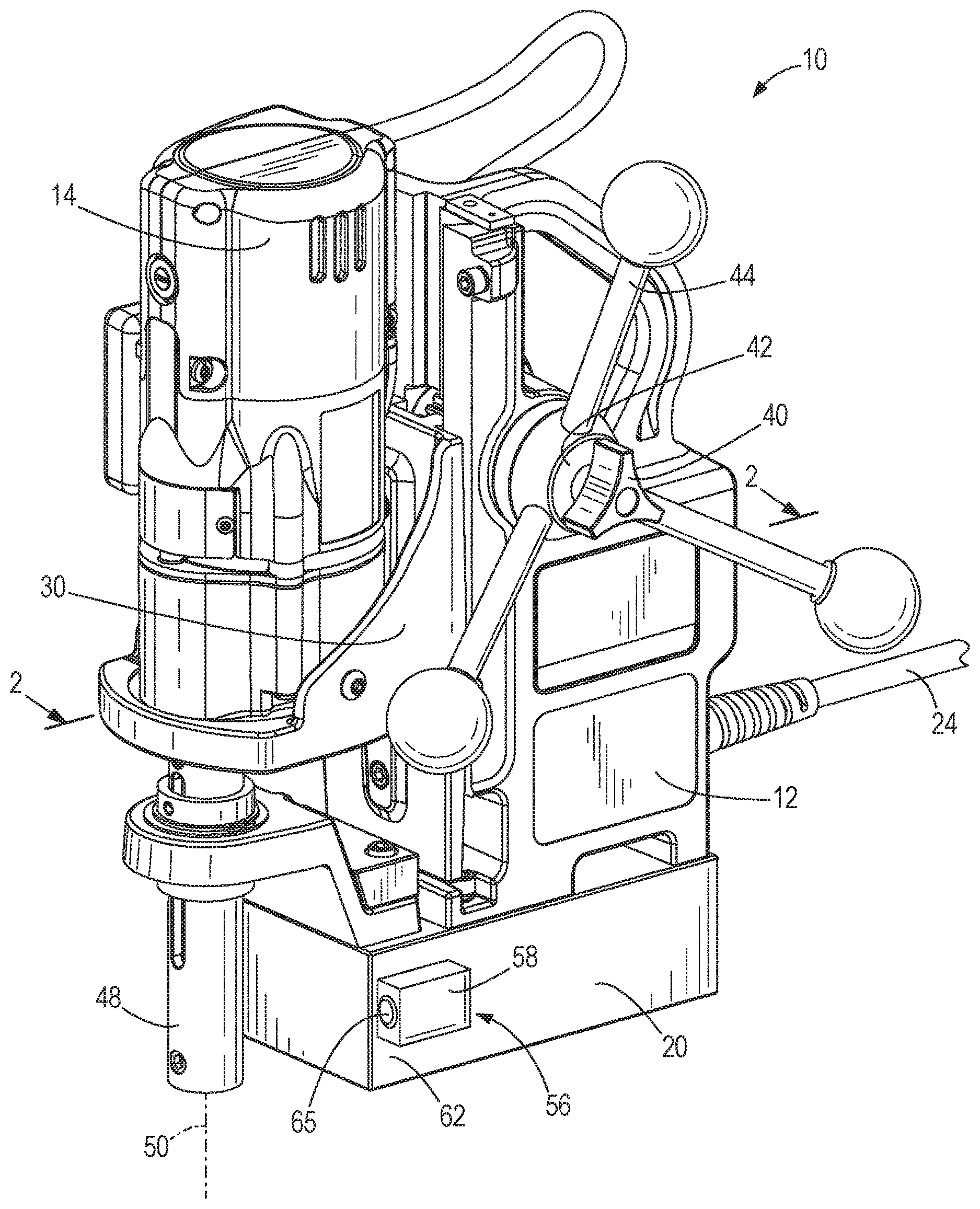
FIG. 1 is a perspective view of a magnetic drill press according to one embodiment of the invention.
FIG. 2 is a sectional view of the magnetic drill press of FIG. 1, along section line 2-2.
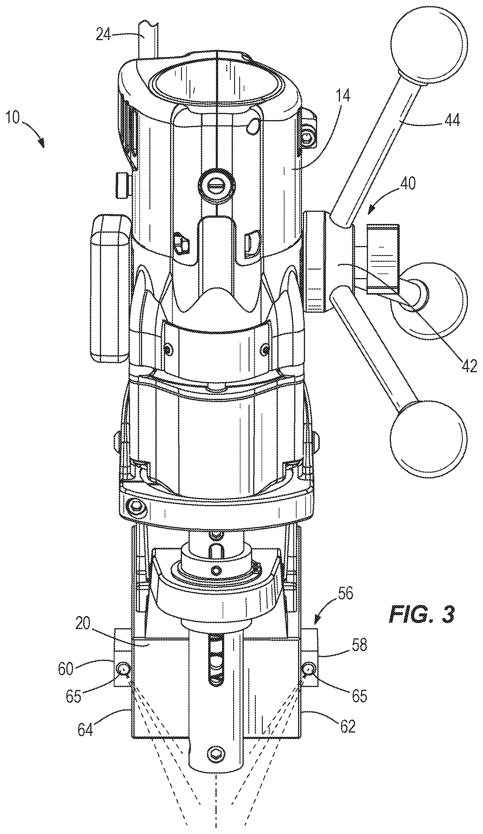
FIG. 3 is a front view of the drill press of FIG. 1.
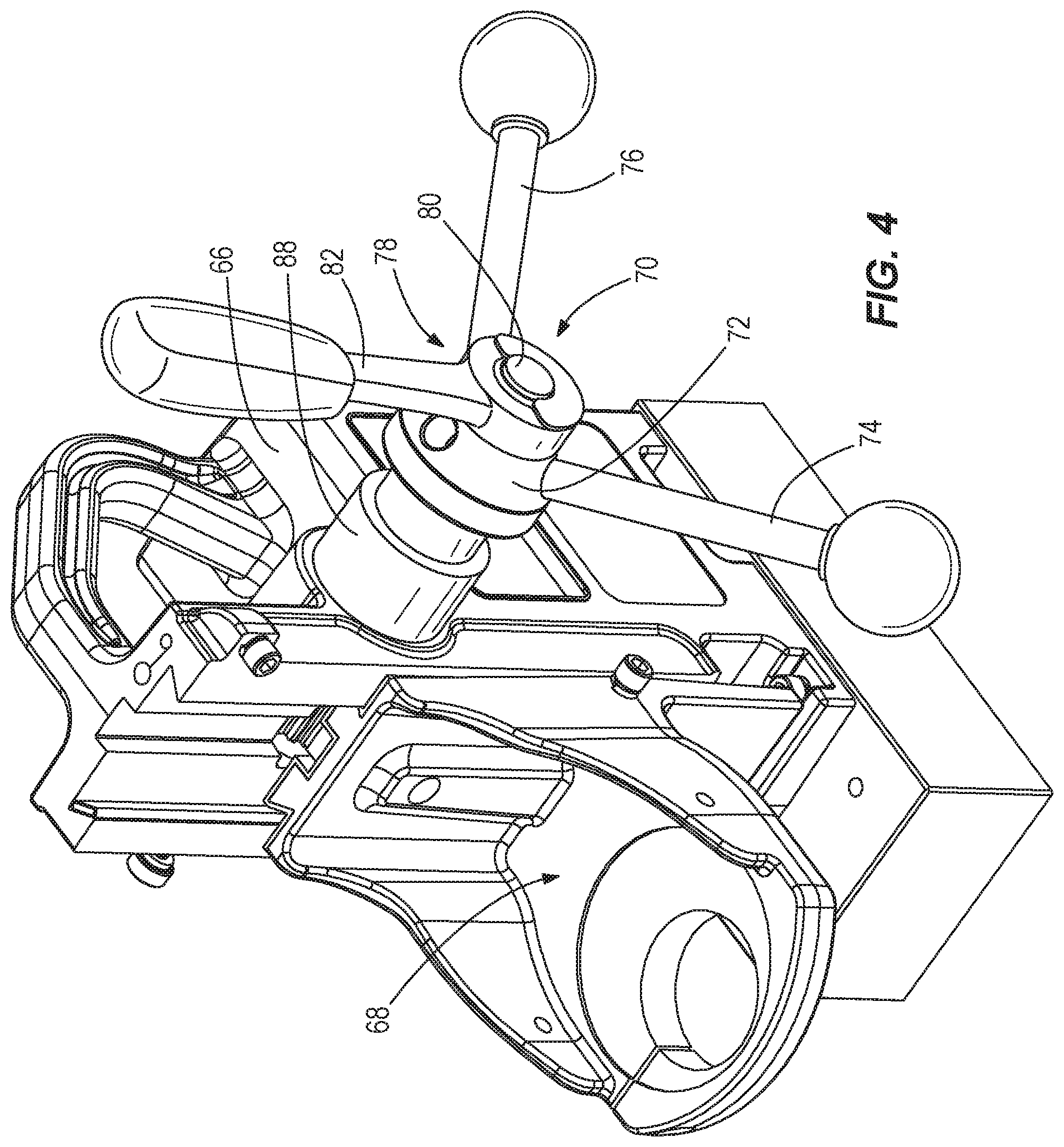
FIG. 4 is a perspective view of a housing and motor carriage assembly of a drill press according to another embodiment of the invention.
FIG. 5 is a perspective view of a handle ratchet assembly of the housing and motor carriage assembly of FIG. 4.
FIG. 6 is a side view of a spindle assembly installed in the housing and motor carriage assembly of FIG. 4.
FIG. 7 is a perspective view of the spindle assembly of FIG. 6.
FIG. 8 is a partially exploded view of the spindle assembly of FIG. 7.
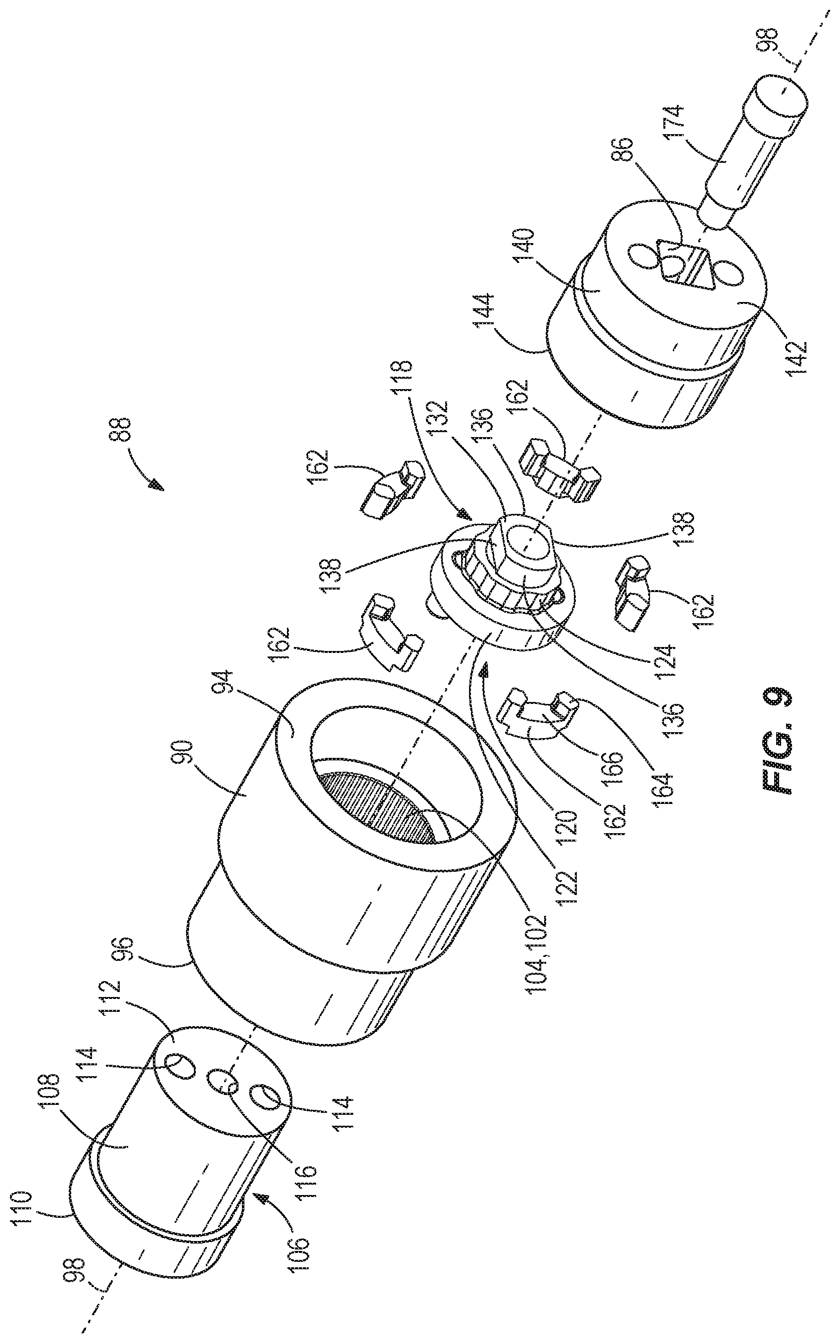
FIG. 9 is an exploded view of the spindle assembly of FIG. 7.
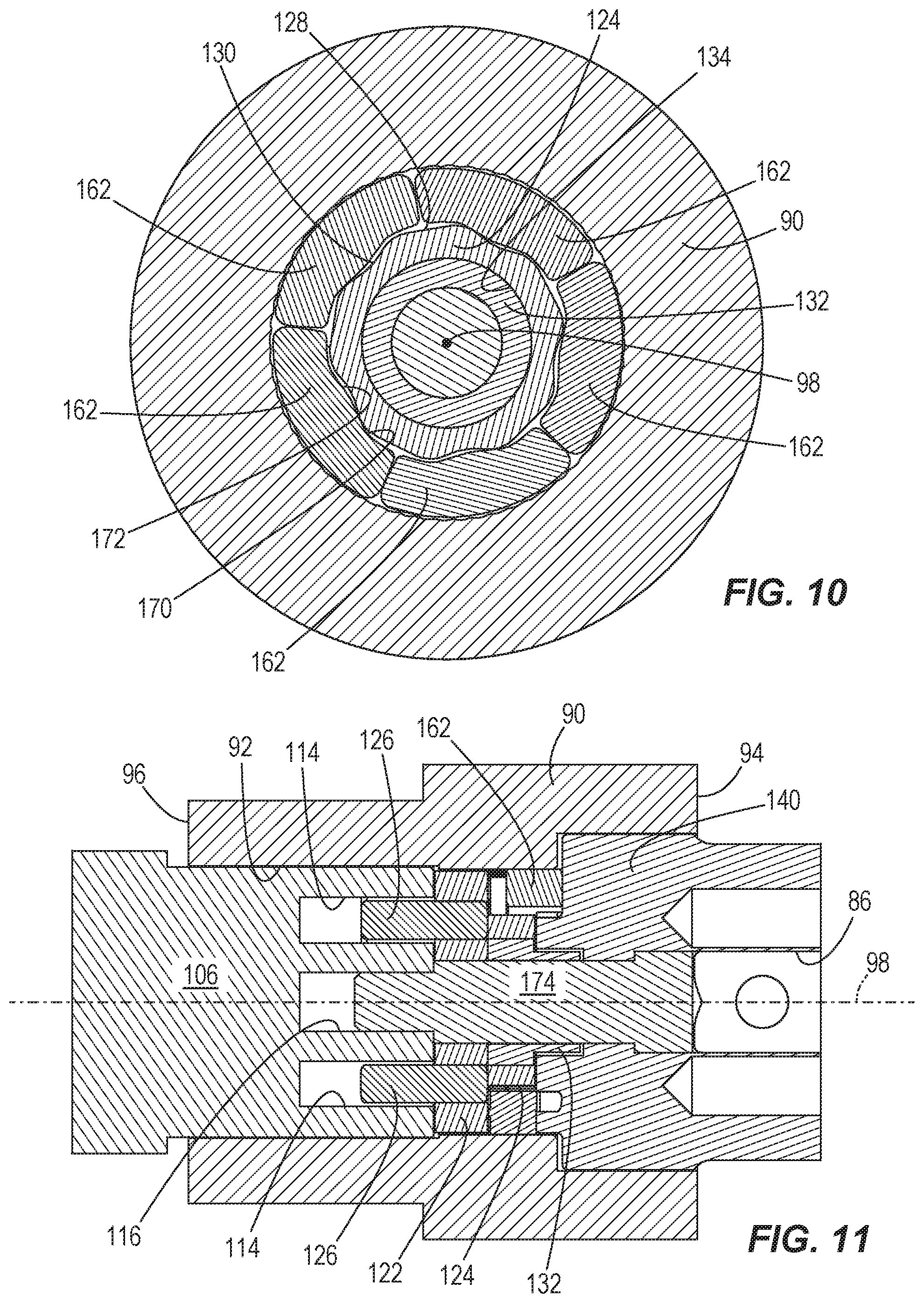
FIG. 10 is a section view of the spindle assembly taken along section line 10-10 of FIG. 7.
FIG. 11 is a section view of the spindle assembly taken along section line 11-11 of FIG. 7.
FIG. 12 is a front view of a magnetic drill press according to another embodiment of the invention.
Before any embodiments of the invention are explained in detail, it is to be understood that the invention is not limited in its application to the details of construction and the arrangement of components set forth in the following description or illustrated in the following drawings. The invention is capable of other embodiments and of being practiced or of being carried out in various ways.
DETAILED DESCRIPTION
FIG. 1 illustrates a drill press 10 according to one embodiment of the invention. The drill press 10 includes a base housing 12 and a motor housing 14. An electric motor 18 is housed within the motor housing 14 (FIG. 2). The drill press 10 further includes a magnetic base 20 for magnetically detachably coupling the drill press 10 and a ferromagnetic workpiece. Once magnetized, the magnetic base 20 secures the drill press 10 to the workpiece via a magnetic field generated by magnets 22 (FIG. 2).
Referring to FIG. 1, the drill press 10 includes an electrical cord 24 to connect to an AC power source, such as a wall outlet or a generator. The AC power source may be a conventional 120V or 240V power source. Referring to FIG. 2, the electric cord 24 is received in the base housing 12 and electrically coupled to a power module 26. A motor control switch 28 is coupled to base housing 12. The motor control switch 28 controls the supply of power to the electric motor 18 from the power module 26.
The motor housing 14 and the motor 18 are coupled to a motor carriage 30. A rack 32 is coupled to the motor carriage 30. A pinion 34 is rotatably coupled to the base housing 12 about a pinion axis 36. The pinion 34 engages the rack 32 for vertical actuation of the motor carriage 30 along a carriage axis 38. The pinion 34 is actuated by a user via a handle assembly 40 (FIG. 1). The handle assembly includes a handle hub 42. Three handle members 44 are coupled to the handle hub 42 in a radial arrangement.
Referring to FIG. 2, the motor 18 is coupled to a bit drive assembly 46. A bit 48 is selectively engageable with the bit drive assembly 46 for rotation about a bit axis 50. The bit axis 50 is substantially parallel to the carriage axis 38. Referring to FIG. 2, the bit drive assembly 46 defines a hollow passage 52 along the bit axis 50.
A laser 54 is disposed within the motor housing 14 for illumination along the bit axis 50. When used in combination with a hollow-centered bit, such as a hole saw, the laser 54 illuminates a workpiece along the bit axis 50. Thus, the laser 54 facilitates alignment of the bit axis 50 with a desired drilling axis. In some embodiments, the laser 54 may be electrically coupled to the power module 26, and selectively controlled by the motor control switch 28 or a separate switch. In other embodiments, the laser 54 may be powered by a separate power supply, such as a battery.
Referring to FIGS. 1 and 3, the drill press 10 includes a workpiece illumination system 56. The workpiece illumination system 56 includes a first illuminator module 58 and, referring to FIG. 3, a second illuminator module 60. The first illuminator module 58 is coupled to a first side portion 62 of the magnetic base 20. The second illuminator module 60 is coupled to a second side portion 64 of the magnetic base 20. Each of the first illuminator module 58 and the second illuminator module 60 includes a light assembly 65, such as an incandescent bulb, or light emitting diode (LED). Each of the first illuminator module 58 and the second illuminator module 62 is aligned to illuminate a work area of the work piece. In some embodiments, the workpiece illumination system 56 may be electrically coupled to the power module 26, and selectively controlled by the motor control switch 28, or a separate switch. In other embodiments, the workpiece illumination system 56 may be powered by a separate power supply, such as a battery.
FIG. 4 illustrates a base housing 66 and motor carriage 68 according to another embodiment of the invention. In the embodiment of FIG. 4, a handle assembly 70 includes a handle hub 72. A first handle member 74 and a second handle member 76 are coupled to the handle hub 72. A ratchet assembly 78 is additionally coupled to the handle hub 72. The ratchet assembly 78 includes a ratchet head portion 80 and a ratchet handle portion 82 coupled to the ratchet head portion 80. The ratchet assembly 78 allows a user to actuate the handle hub 72 with reciprocating motion of the ratchet handle portion 82.
Referring to FIG. 5, the handle hub 72 includes a drive member 84. The drive member 84 is configured to be received by a square drive socket 86 of a spindle assembly 88 (FIG. 6). The spindle assembly 88 acts as an interface between the handle assembly 70 and the base housing pinion, such as the pinion 34 of FIG. 2.
Referring to FIG. 7, the spindle assembly 88 includes a collar 90. The collar 90 is fixedly coupled to the base housing 66, as illustrated in FIG. 6. Referring to FIG. 11, the collar 90 has a hollow center 92 extending between a handle end 94 and a pinion end 96 along a spindle axis 98. Referring to FIG. 9, the collar 90 defines a toothed portion 102 between the handle end 94 and the pinion end 96. The toothed portion 102 includes axially-extending, radially projecting, tooth members 104.
An inner spindle 106 is rotatably coupled to the collar 90. The inner spindle 106 includes a substantially cylindrical body 108, extending from a pinion end 110 to a hub end 112 along the pinion axis 98. The pinion end 110 is coupled to the pinion 34 (FIG. 2) for rotation of the pinion 34 about the pinion axis 36 and, thereby, to actuate the rack 32 of the motor carriage 30. Referring to FIG. 9, the hub end 112 of the inner spindle 106 defines two engagement recesses 114 and a threaded aperture 116.
A spindle hub assembly 118 includes a hub body 120. The hub body 120 includes a cylindrical portion 122 and a dog actuator portion 124. Referring to FIG. 11, the cylindrical portion 122 receives two drive pins 126 for driving engagement with the engagement recesses 114 of the inner spindle 106. Referring to FIG. 10, the dog actuator portion 124 defines five radial lobes 128 and five radial recesses 130, with the radial lobes 128 and radial recesses 130 alternating circumferentially about the spindle axis 98. Referring to FIG. 9, the dog actuator portion 124 also receives a torque transfer link 132. More specifically, the torque transfer link 132 is fixedly received in a circular recess 134 defined in the dog actuator portion 124. The torque transfer link 132 defines a pair of opposing convex surfaces 136, separated by a pair of flat, mutually parallel surfaces 138.
Referring to FIGS. 7 and 10, an outer spindle 140 is rotatably coupled to the collar 90 at the handle end 94. The outer spindle 140 defines, on a first end 142, the square drive socket 86 to which the handle assembly 70 is selectively coupled. Referring to FIG. 8, a dog carrier hub 144 and five dog lugs 146 extend axially from the second end 148 of the outer spindle 140. Each of the dog carrier lugs 146 extends radially from a substantially circular dog hub 148. In the illustrated embodiment, five dog carrier lugs 146 are circumferentially evenly arranged about the spindle axis 98. Each dog carrier lug 146 defines a first alignment surface 150, a second alignment surface 152, and a circumferential surface 154.
The dog hub 148 defines a torque transfer recess 156. The torque transfer recess 156 includes a pair of opposing convex walls 158, separated by a pair of opposing concave wall 160. The torque transfer recess 156 is configured to rotatably receive the torque transfer link 132. More specifically, the convex surfaces 160 of the torque transfer recess 156 allow for a small degree of relative rotation (e.g., less than ten degrees) between the outer spindle 140 and the torque transfer link 132.
Referring to FIG. 9, five dog members 162 are arranged circumferentially about the pinion axis 98, between the outer spindle 140 and the hub body 120. An outer end 164 of each dog member 162 defines a groove 166 configured to receive the dog carrier lugs 146. Referring to FIG. 8, non-radial side walls 168 of the grooves 166 are configured to be engaged by the first alignment surface 150 or second alignment surface 152 of the dog carrier lugs 146. Referring to FIG. 10, an inner radial surface 170 of each dog member 162 defines a dog cam lobe 172.
Referring to FIGS. 9 and 11, the spindle assembly 88 is assembled with a shoulder bolt 174. More specifically, the shoulder bolt 174 extends through the outer spindle 140 and the hub assembly 118 to threadedly engage the threaded recess 116 of the inner spindle 106. The dog members 162 float between the outer spindle 140, the hub assembly 118, and the hollow center 92 of the collar 90.
When the handle assembly 70 (FIG. 4) is actuated by a user to, for example, drive a bit into a work piece, the drive member 84 (FIG. 5) transmits torque to the outer spindle 140 at the square drive socket 86 (FIG. 7). After a small degree of rotation (e.g., less than 10 degrees), torque applied to the outer spindle is transmitted to torque transfer link 132 via the torque transfer recess 156 of the outer spindle (FIG. 8). Referring to FIG. 11, from the torque transfer link 132, torque is transmitted through the cylindrical portion 122. From the cylindrical portion 122, the torque is transferred to the inner spindle 106 via the drive pins 126. Simultaneously, and with reference to FIG. 8, the first alignment surfaces 150 or second alignment surfaces 152 (depending upon a direction of rotation about the spindle axis 98) of the dog carrier lugs 146 engage the non-radial side walls 168 of the dog members 162 and biases the dog members 162 radially inward, thereby substantially preventing the dog members 162 from binding engagement with the teeth 104 (FIG. 9) of the collar 90.
When a user releases the handle assembly 70 (FIG. 4), the dog carrier lugs 146 no longer force the dog members 162 in an inwardly radial direction. Furthermore, any torque applied to the inner spindle 106 (e.g., from the weight of the motor carriage 68) causes the hub assembly 118 to rotate relative to the outer spindle 140, until the torque transfer link 132 reengages the torque transfer recess 156 (e.g., less than ten degrees of rotation). Referring to FIG. 10, the rotation of the hub assembly 118 causes the radial lobes 128 of the dog actuator portion 124 to engage the dog cam lobes 172, thereby forcing the dog members 162 radially outward, and into engagement with the teeth 104 of the collar 90. Engagement of the dogs 162 with the collar 90 substantially inhibits further rotation of the inner spindle 106, effectively causing "spindle lock." In order to disengage the spindle lock condition, a user merely applies torque through the outer spindle 140 (via the handle assembly 70), thereby disengaging the dog members 162 from the teeth 104 of the collar 90 by applying an inward radial force from the dog carrier lugs 146. This substantially automatic spindle lock operation is especially advantageous when using the ratchet assembly 78, as the spindle assembly 88 maintains its position while cycling the ratchet assembly 78.
FIG. 12 illustrates another embodiment of a drill press 178. The drill press has substantial similarities to the drill press 10 described with respect to FIGS. 1-11, and only those aspects that differ from the embodiments of FIGS. 1-11 will be described herein.
The drill press 178 includes a base housing 182, and a motor housing 186. Referring to FIG. 12, the drill press 178 further includes a magnetic base 190 for magnetically detachably coupling the drill press 178 and a ferromagnetic workpiece.
Referring to FIG. 12, the drill press 178 includes a workpiece illumination system 194. The workpiece illumination system 194 is coupled to a top portion 198 of the magnetic base 190. The workpiece illumination system 194 includes a first illuminator module 202 and a second illuminator module 206. Each of the first illuminator module 202 and the second illuminator module 206 includes a light assembly 210, such as an incandescent bulb, or light emitting diode (LED). Each of the first illuminator module 202 and the second illuminator module 206 is aligned to illuminate a work area of the work piece. In the illustrated embodiment, the first illuminator 202 and the second illuminator 206 are aligned to illuminate a work area along the bit axis 50.
Thus, the invention provides, among other things, a magnetic-base drill press. Various features and advantages of the invention are set forth in the following claims.
* * * * *
D00000
D00001
D00002
D00003
D00004
D00005
D00006
D00007
D00008
D00009
XML
uspto.report is an independent third-party trademark research tool that is not affiliated, endorsed, or sponsored by the United States Patent and Trademark Office (USPTO) or any other governmental organization. The information provided by uspto.report is based on publicly available data at the time of writing and is intended for informational purposes only.
While we strive to provide accurate and up-to-date information, we do not guarantee the accuracy, completeness, reliability, or suitability of the information displayed on this site. The use of this site is at your own risk. Any reliance you place on such information is therefore strictly at your own risk.
All official trademark data, including owner information, should be verified by visiting the official USPTO website at www.uspto.gov. This site is not intended to replace professional legal advice and should not be used as a substitute for consulting with a legal professional who is knowledgeable about trademark law.