Method for producing a body implant, assembly consisting of a guide wire and a body implant, and a medical instrument
Feth , et al.
U.S. patent number 10,583,531 [Application Number 15/450,994] was granted by the patent office on 2020-03-10 for method for producing a body implant, assembly consisting of a guide wire and a body implant, and a medical instrument. This patent grant is currently assigned to Admedes Schuessler GmbH. The grantee listed for this patent is Admedes Schuessler GmbH. Invention is credited to Nils-Agne Feth, Alexander Lange, Ralf Steiner.


| United States Patent | 10,583,531 |
| Feth , et al. | March 10, 2020 |
Method for producing a body implant, assembly consisting of a guide wire and a body implant, and a medical instrument
Abstract
The invention relates to a method for producing a body implant comprising the steps of: providing a wire; producing predetermined cuts of the cross section of the wire by means of an ultrashort pulse laser in order to produce a predetermined shape of the body implant. This method can be used to produce, for example, a body implant, an assembly consisting of a guide wire and a body implant, or a medical instrument having a guide wire.
| Inventors: | Feth; Nils-Agne (Waldbronn, DE), Lange; Alexander (Karlsruhe, DE), Steiner; Ralf (Pforzheim, DE) | ||||||||||
|---|---|---|---|---|---|---|---|---|---|---|---|
| Applicant: |
|
||||||||||
| Assignee: | Admedes Schuessler GmbH
(Pforzheim, DE) |
||||||||||
| Family ID: | 47683682 | ||||||||||
| Appl. No.: | 15/450,994 | ||||||||||
| Filed: | March 6, 2017 |
Prior Publication Data
| Document Identifier | Publication Date | |
|---|---|---|
| US 20170173738 A1 | Jun 22, 2017 | |
Related U.S. Patent Documents
| Application Number | Filing Date | Patent Number | Issue Date | ||
|---|---|---|---|---|---|
| 14404336 | 10434605 | ||||
| PCT/EP2013/000185 | Jan 22, 2013 | ||||
Foreign Application Priority Data
| May 30, 2012 [DE] | 10 2012 010 687 | |||
| Current U.S. Class: | 1/1 |
| Current CPC Class: | A61F 2/91 (20130101); A61F 2/89 (20130101); A61F 2/01 (20130101); B23K 26/364 (20151001); A61B 17/221 (20130101); B23K 26/0624 (20151001); A61F 2240/001 (20130101); A61F 2210/0014 (20130101); A61F 2230/0097 (20130101); A61B 2017/00526 (20130101); A61F 2230/005 (20130101); A61F 2002/018 (20130101); B23K 2101/32 (20180801); A61B 2017/00867 (20130101); A61B 2017/2212 (20130101) |
| Current International Class: | B23K 26/364 (20140101); A61F 2/91 (20130101); A61F 2/01 (20060101); A61F 2/89 (20130101); A61B 17/221 (20060101); B23K 26/0622 (20140101); A61B 17/00 (20060101) |
References Cited [Referenced By]
U.S. Patent Documents
| 5376100 | December 1994 | Lefebvre et al. |
| 5495668 | March 1996 | Furusawa et al. |
| 5573520 | November 1996 | Schwartz et al. |
| 5707387 | January 1998 | Wijay et al. |
| 5916235 | June 1999 | Guglielmi |
| 5980514 | November 1999 | Kupiecki et al. |
| 6022369 | February 2000 | Jacobsen et al. |
| 6160240 | December 2000 | Momma et al. |
| 6190402 | February 2001 | Horton et al. |
| 6258117 | July 2001 | Camrud et al. |
| 6299612 | October 2001 | Ouchi et al. |
| 6398791 | June 2002 | Que et al. |
| 6402771 | June 2002 | Palmer et al. |
| 6551342 | April 2003 | Shen et al. |
| 6579246 | June 2003 | Jacobsen et al. |
| 6893450 | May 2005 | Foster et al. |
| 7060083 | June 2006 | Gerberding et al. |
| 7377925 | May 2008 | Poll et al. |
| 7524322 | April 2009 | Monstadt et al. |
| 7632242 | December 2009 | Griffin et al. |
| 7771410 | August 2010 | Venturelli et al. |
| 7828832 | November 2010 | Belluche et al. |
| 7850708 | December 2010 | Pal et al. |
| 7857008 | December 2010 | Chen et al. |
| 7914466 | March 2011 | Davis et al. |
| 7914467 | March 2011 | Layman et al. |
| 8016870 | September 2011 | Chew et al. |
| 8251963 | August 2012 | Chin et al. |
| 8292827 | October 2012 | Musbach et al. |
| 8323241 | December 2012 | Salahieh et al. |
| 8409114 | April 2013 | Parins et al. |
| 8523879 | September 2013 | Lind et al. |
| 8529596 | September 2013 | Grandfield et al. |
| 8708953 | April 2014 | Salahieh et al. |
| 8795254 | August 2014 | Layman et al. |
| 8821477 | September 2014 | Northrop et al. |
| 8876772 | November 2014 | Weber et al. |
| 8961550 | February 2015 | Lenker et al. |
| 9011480 | April 2015 | Divino et al. |
| 9067332 | June 2015 | Lippert et al. |
| 9067333 | June 2015 | Lippert et al. |
| 9072874 | July 2015 | Northrop et al. |
| 9144665 | September 2015 | Salstrom et al. |
| 9149609 | October 2015 | Ansel et al. |
| 9717612 | August 2017 | Dorn et al. |
| 9795307 | October 2017 | Radman et al. |
| 9795765 | October 2017 | Romoscanu et al. |
| 2001/0041899 | November 2001 | Foster |
| 2002/0010481 | January 2002 | Jayaraman et al. |
| 2002/0065553 | May 2002 | Weber |
| 2004/0138677 | July 2004 | Little et al. |
| 2005/0182390 | August 2005 | Shanley et al. |
| 2007/0010762 | January 2007 | Ressemann et al. |
| 2007/0043413 | February 2007 | Eversull et al. |
| 2007/0067019 | March 2007 | Miller et al. |
| 2007/0112373 | May 2007 | Carr, Jr. et al. |
| 2007/0142901 | June 2007 | Steinke et al. |
| 2007/0225729 | September 2007 | Cheng et al. |
| 2008/0039930 | February 2008 | Jones et al. |
| 2008/0208211 | August 2008 | Uihlein et al. |
| 2008/0312597 | December 2008 | Uihlein et al. |
| 2009/0088832 | April 2009 | Chew et al. |
| 2009/0248133 | October 2009 | Bloom et al. |
| 2010/0102046 | April 2010 | Huang et al. |
| 2010/0168758 | July 2010 | Uihlein et al. |
| 2010/0318115 | December 2010 | Chanduszko et al. |
| 2011/0009950 | January 2011 | Grandfield et al. |
| 2011/0070358 | March 2011 | Mauch et al. |
| 2011/0160838 | June 2011 | Blanzy et al. |
| 2011/0245907 | October 2011 | Pacetti et al. |
| 2011/0288630 | November 2011 | Blanzy et al. |
| 2011/0319988 | December 2011 | Schankereli et al. |
| 2012/0046687 | February 2012 | Trommeter et al. |
| 2013/0289701 | October 2013 | Coghlan et al. |
| 2015/0165558 | June 2015 | Feth et al. |
| 2018/0008439 | January 2018 | Tieu |
| 197 22 429 | Dec 1998 | DE | |||
| 197 45 294 | Apr 1999 | DE | |||
Other References
|
International Search Report and Written Opinion for PCT/EP2013/000185, dated Apr. 4, 2013, 10 pages. cited by applicant . Official Communication for corresponding EP Application No. 13 703 522.6-1651, dated Apr. 22, 2014, 5 pages. cited by applicant . International Preliminary Report on patentability for PCT/EP2013/000185, dated Dec. 11, 2014, 6 pages. cited by applicant. |
Primary Examiner: Hong; John C
Attorney, Agent or Firm: Harrity & Harrity, LLP
Parent Case Text
RELATED APPLICATIONS
This application is a divisional of U.S. patent application Ser. No. 14/404,336, filed Dec. 10, 2014, which claims priority to PCT Application No. PCT/EP2013/000185, filed Jan. 22, 2013, which claims priority to German Application No. 10 2012 010 687.4, filed May 30, 2012, the contents of which are incorporated herein by reference.
Claims
The invention claimed is:
1. A method comprising: providing a wire; producing cuts on the wire by means of an ultrashort pulse laser in order to produce a shape of a body implant; and producing one or more other cuts on the wire in a manner that provides a predetermined breaking point between a guide wire, formed from the wire, and the body implant, wherein the cuts do not extend up to a first axial end or a second axial end of the wire.
2. The method according to claim 1, wherein the cuts are produced substantially in radial direction, wherein a cut segment of the wire or a wire segment is expanded in order to produce the body implant, and wherein the body implant is a closed basket or a filter.
3. The method according to claim 1, wherein a portion of cross section of the wire is removed in order to produce a joint.
4. The method according to claim 1, further comprising: braiding or tatting wire segments and/or shaping wire segments.
5. The method according to claim 1, wherein the wire is made of a material having shape-memory properties.
6. The method according to claim 1, wherein the predetermined breaking point is configured for the body implant to be separated from the guide wire after positioning of the body implant in a body.
7. The method according to claim 1, further comprising: separating wire segments, with different cross-sections, from the wire.
8. The method according to claim 7, wherein the body implant has varying supporting powers along a circumference of the body implant due to the wire segments being separated.
9. The method according to claim 1, wherein the wire is made of a material having shape-memory properties.
10. The method according to claim 1, wherein the cuts extend to a center of the wire.
11. The method according to claim 1, wherein a height of a cut, of the cuts, is smaller than a radius of the wire.
12. A method comprising: providing a wire; dividing the wire into individual wire segments in order to produce a shape of a body implant; and producing one or more other cuts on the wire in a manner that provides a predetermined breaking point between a guide wire, formed from the wire, and the body implant.
13. The method according to claim 12, further comprising: expanding the wire segments into the shape of the body implant.
14. The method according to claim 12, wherein the wire segments are integrally connected to at least one of a first axial end or a second axial end of the wire.
15. The method according to claim 14, wherein the first axial end and the second axial end are not separated after the cuts.
16. A method comprising: providing a wire; producing cuts on the wire in order to produce a shape of a body implant; and crimping the body implant to an original diameter of the wire.
17. The method according to claim 16, wherein the cuts do not extend up to a first axial end or a second axial end of the wire.
18. The method of claim 16, wherein a cut segment of the wire or a wire segment is expanded in order to produce the body implant.
Description
The present invention relates to a method for producing a body implant, an assembly consisting of a guide wire and a body implant, and a medical instrument.
Conventionally, body implants and medical instruments, such as stents, baskets, filters or catching devices are made of hollow round material, like e.g. a tube. Alternatively or additionally, such devices may be produced by braiding wires. This measure, however, involves high production expenditure, and devices produced in this way have a limited crimp capability, i.e. a capability of reducing their diameter for insertion into the human body. Thus, there is need for a method and for devices produced by this method, having a higher crimp capability and a simpler production method.
Thus, the object of the invention is to provide a simplified method and corresponding devices which simplify the production of stents, baskets, filters and the like, and which allow for higher crimp capability.
This object is accomplished by the features of the independent claims. Advantageous embodiments of the invention are defined in the dependent claims.
According to one aspect, the invention relates to a method for producing a body implant, comprising the steps of:
providing a wire,
producing cuts, or notches, or structures, respectively, on the wire's cross section using an ultrashort pulse laser, in order to produce a predetermined shape of the body implant.
Preferably, the cuts are produced substantially in radial direction, and a cut portion of the wire, or a wire segment, is expanded in order to produce a body implant, such as a closed basket or a filter, stent or the like.
A part, preferably the major part of the wire's cross section can be removed by the cuts, for example, in order to produce a joint.
Still preferentially, the method can further include the step of braiding wire segments and/or a step of shaping wire segments.
Preferably, a wire is used which is made of a material having shape-memory properties, such as Nitinol.
The ultrashort pulse laser technology allows for micro treatment of materials, such as wires without having to expel the removed material, such as re-solidified mass in the case of conventional laser fusion cutting. Hence, a process of cold removal, a so-called ablation process, takes place. In contrast to conventional laser fusion cutting where only continuous cuts can be made, there is the possibility of structuring a wire, on the one hand, thus altering the mechanical and/or electrical or electronic properties. On the other hand, this process allows for slitting very fine wires symmetrically as well as asymmetrically by cuts. Thus, by producing radial cuts in the wire, wire segments can be separated from the wire, and subsequently can be shaped and/or expanded in order to produce a basket, a stent, or a filter, for example. Moreover, the wire segments can be braided in order to systematically manipulate mechanical and electrical or electronic properties.
Moreover, the cuts or notches or structures, respectively, can be produced such that an integrally formed joint is produced from the wire by means of removing a major part of the cross section. Thus, numerous configurations are possible by means of generating corresponding cuts on a wire using the ultrashort pulse laser technology.
According to a further aspect, the invention relates to an assembly consisting of a guide wire and a body implant produced by means of such a method, with the guide wire and the body implant being integrally, or monolithically, formed and having a predetermined breaking point. Herein, the guide wire can have at least an integrally formed joint in order to increase the flexibility or bending property of the guide wire.
Preferably, the assembly has at least one of a stent, a basket or a filter.
According to a further aspect, a medical instrument having a guide wire is provided that is produced using this method. Therein, the guide wire can have at least an integrally formed joint.
The advantage of this manufacturing technology is that an assembly consisting of a guide wire and a body implant, or a medical instrument, respectively, can be made of one piece, such that connecting a guide wire with a body implant by means of micro welding, for example, is no longer necessary. Thus, a fault susceptibility of a corresponding assembly consisting of a guide wire and a medical instrument is considerably reduced.
This integrally formed assembly can have a predetermined breaking point such that the body implant, or the medical instrument, is separated from the guide wire after positioning in the human body in order to remove the guide wire. Further, the production process is highly simplified. Moreover, the guide wire can have an integrally formed joint in order to provide higher flexibility.
This technology has the advantage of having lower raw material costs, is mechanically stronger and has maximal crimp capability, since the expanded wire segments can be deformed or crimped so as to assume the original position of the uncut wire, in order to reduce the diameter for insertion into the human body to a minimal diameter. Moreover, the device can be produced with a minimal number of production steps.
The invention will now be explained in more detail based on exemplary embodiments with reference to the accompanying drawings.
FIG. 1 shows a circular wire being cut by a laser beam in radial direction approximately up to its center.
FIG. 2 shows the production of five cuts in total in a radial direction up to the wire's center.
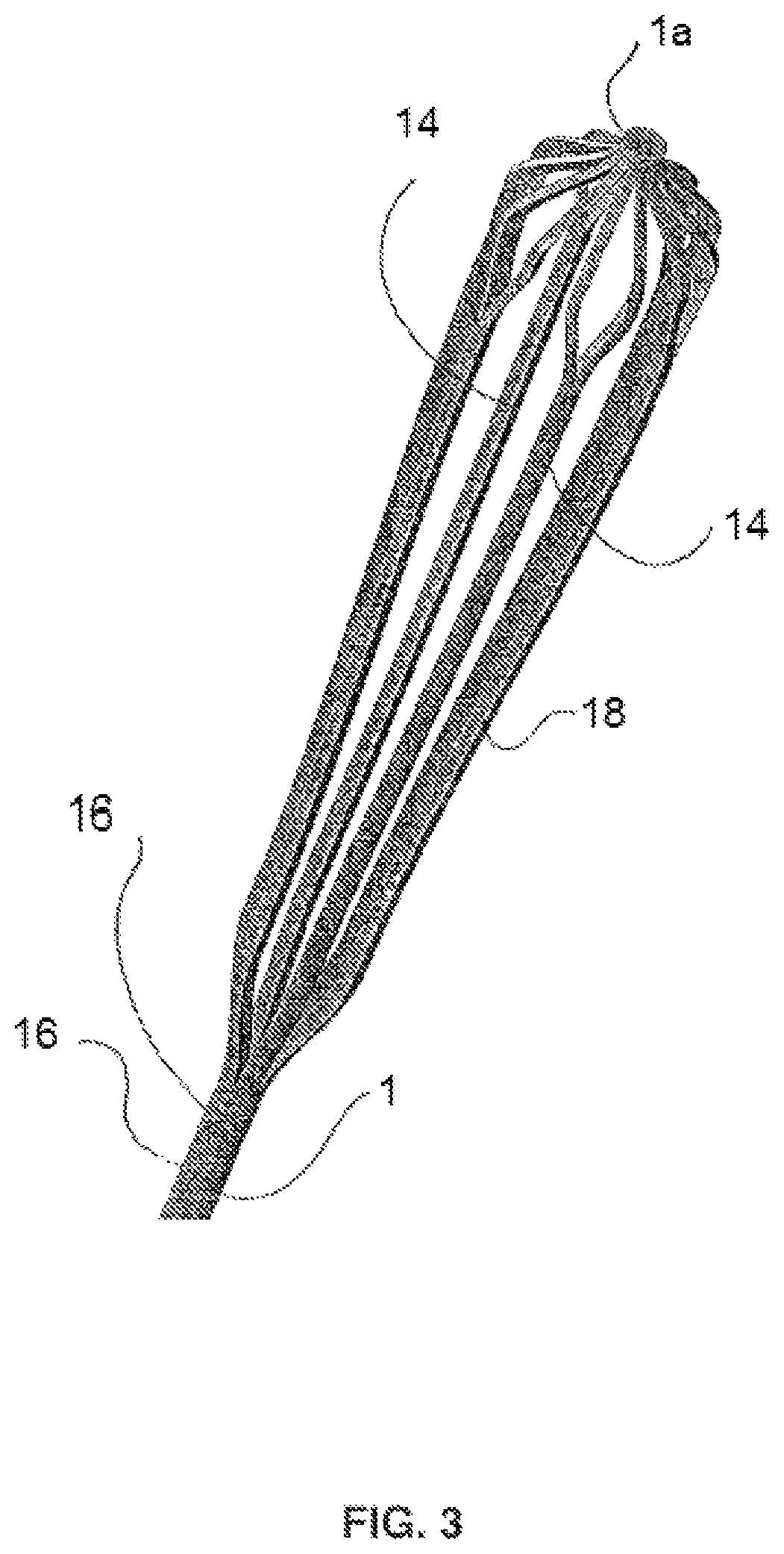
FIG. 3 shows a design of a basket or filter produced by the cuts wherein the cut wire segments are subsequently expended.
FIG. 4 shows a guide wire exhibiting high bending property or flexibility due to the generation of corresponding cuts.
FIG. 5 shows a stent integrally formed with the guide wire and having a predetermined breaking point.
FIG. 6 shows a controllable guide wire.
FIG. 7 shows a detailed view of the guide wire of FIG. 6 with a corresponding joint for bending the guide wire.
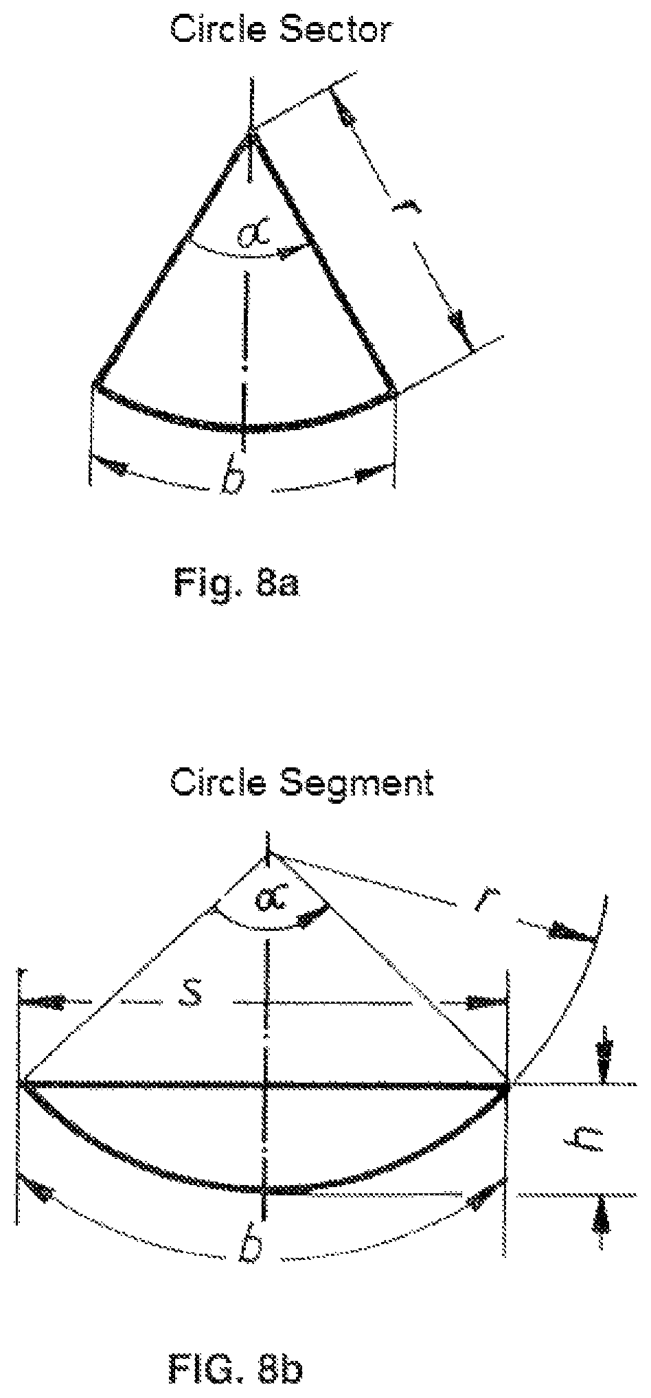
FIG. 8a shows a wire segment formed as a circle sector, and FIG. 8b shows a wire segment formed as a circle segment.
As shown in FIG. 1, a circular wire 1 is cut in up to approximately the center thereof by means of a laser beam L using the ultrashort pulse laser technology, in order to generate a cut 12. Although circular wires are advantageously used for this technology, the invention is not restricted thereto. Wires having elliptical cross sections, triangular, square, pentagon wires, or the like can also be used.
Advantageously, an ultrashort pulse laser having a wavelength of about 200 to about 2000 nm is used therein. The pulse width should be about 10 fs to about 10 ps.
Further, for example, five radial cuts extending to the center of the wire can be generated, in order to produce wire segments or cut sectors 14, as shown in FIG. 2. These cut sectors or wire segments 14 subsequently can be expanded by deformation so as to produce, for example, a basket or filter design, as shown for example in FIG. 3. Therein, the cuts do not extend up to an axial end 1a, 1b of the wire 1, such that the individual wire segments 14 remain connected in longitudinal directions at their ends.
In this manner, a basket or filter design, respectively, is produced having wire segments 14 which are integrally connected at their ends 1a, 1b.
This means that the wire 1 is divided, like a pie, into individual segments (wire segments 14), wherein axial ends 1a, 1b of the wire are not separated. The separated wire segments 14 are expanded such that a body is generated having spaced wire segments 14 in the axial center and axial ends 1a, 1b which are integrally connected to the wire segments 14.
It should be appreciated that the invention can also be realized with three, four, six or seven cuts 12, etc. Therein, the cuts 12 do not have to be set at regular angular distances, but "pieces of pie", or wire segments 14, of different sizes can be generated.
Moreover, the wire segments 14 do not have to be generated as a circle sector having the length of the radius r of the wire 1 as sides of the circle sector, i.e. by means of cuts 12 ending at the center of the wire cross-section, as shown in FIG. 8a, but any forms can be separated from the wire cross-section, such as a circle segment, as shown for example in FIG. 8b.
A circle segment, as shown in FIG. 8b, is separated from the wire cross-section by producing a cut 12 offset from the center of the wire cross-section along the chord length s. Therein, a height h of the cut 12 is smaller than the radius r of the wire.
By means of separating wire segments 14 with different cross sections from the wire cross-section in this manner, and expanding them subsequently, a stent can be generated, for example, having varying supporting powers along the circumference thereof.
These wire segments 14 can be deformed or treated according to the desired mechanical and/or electrical properties by further shaping by means of forming or by further laser treatment. Moreover, the wire segments 14 can be braided, e.g. by tatting the wire segments with the weave types 1/2, 1/1, or 2/2.
The basket or filter design, or stent 18, respectively, produced this way can subsequently be separated from the wire 1. It can, however, also remain connected to a longer piece of wire 1 such that the uncut end of the wire 1 is used as a guide wire 16, as shown for example in FIGS. 4 and 5.
A predetermined breaking point 20 can be provided between the guide wire 16 and the body implant 18 generated, such that the assembly consisting of the guide wire 16 and the body implant 18, which is integrally formed in this manner, can be separated at the predetermined breaking point 20 after insertion and positioning of the body implant 18, in order to remove the guide wire 16 after positioning of the body implant 18. Therein, the guide wire 16 can have corresponding cuts 12 or sectional weakenings or structures, respectively, in order to provide for high flexibility or bending property. The predetermined breaking point 20 has a corresponding sectional weakening 20a, in order to facilitate breaking or separating at the predetermined breaking point 20.
As further shown in FIGS. 6 and 7, a corresponding joint 17 can be produced by a cut wherein almost the whole cross section of the wire or guide wire 16, respectively, is removed, around which joint one end of the guide wire 16 can be bent with respect to another segment.
Thus a variety of design possibilities is provided by correspondingly cutting a wire 1 using the ultrashort pulse laser technology, and by expanding and, if applicable, further treating the cut wire segments 14. Thus, a body implant 18, e.g. a stent, a basket, or a filter can be produced as one piece in a simple manner. Moreover, this body implant 18 can be crimped to the original wire diameter in order to achieve maximal reduction of diameter.
Preferably, a wire 1 is used which is made of a material having shape-memory properties, such as Nitinol. However, other metals or nonmetals can also be employed.
The invention is not limited to the production of radial cuts 12, but cuts can be made also in other directions. Moreover, the cuts 12 do not have to reach the center of the wire 1, but depending on the application can be produced with less or more depth.
Structures or notches on the cross section of the wire 1 can be generated thereby.
LIST OF REFERENCE SIGNS
1 wire 12 cut 14 wire segment 16 guide wire 17 joint 18 body implant (stent) 20 predetermined breaking point 20a sectional weakening L laser
* * * * *
D00000
D00001
D00002
D00003
D00004
D00005
D00006
D00007
D00008
XML
uspto.report is an independent third-party trademark research tool that is not affiliated, endorsed, or sponsored by the United States Patent and Trademark Office (USPTO) or any other governmental organization. The information provided by uspto.report is based on publicly available data at the time of writing and is intended for informational purposes only.
While we strive to provide accurate and up-to-date information, we do not guarantee the accuracy, completeness, reliability, or suitability of the information displayed on this site. The use of this site is at your own risk. Any reliance you place on such information is therefore strictly at your own risk.
All official trademark data, including owner information, should be verified by visiting the official USPTO website at www.uspto.gov. This site is not intended to replace professional legal advice and should not be used as a substitute for consulting with a legal professional who is knowledgeable about trademark law.