Robotic surgical devices, systems, and related methods
Wilson , et al.
U.S. patent number 10,582,973 [Application Number 13/833,605] was granted by the patent office on 2020-03-10 for robotic surgical devices, systems, and related methods. This patent grant is currently assigned to Virtual Incision Corporation. The grantee listed for this patent is Virtual Incision Corporation. Invention is credited to Shane Farritor, Jason Herman, Nishant Kumar, Matt Mahin, Erik Mumm, Chris Santoro, Jeff Shasho, John Wilson.


View All Diagrams
| United States Patent | 10,582,973 |
| Wilson , et al. | March 10, 2020 |
Robotic surgical devices, systems, and related methods
Abstract
The embodiments disclosed herein relate to various medical device components, including components that can be incorporated into robotic and/or in vivo medical devices. Certain embodiments include various modular medical devices for in vivo medical procedures.
| Inventors: | Wilson; John (Brooklyn, NY), Shasho; Jeff (Brooklyn, NY), Kumar; Nishant (Bergenfield, NJ), Mahin; Matt (Longmont, CO), Santoro; Chris (Brooklyn, NY), Mumm; Erik (Longmont, CO), Herman; Jason (East Northport, NY), Farritor; Shane (Lincoln, NE) | ||||||||||
|---|---|---|---|---|---|---|---|---|---|---|---|
| Applicant: |
|
||||||||||
| Assignee: | Virtual Incision Corporation
(Lincoln, NE) |
||||||||||
| Family ID: | 50066740 | ||||||||||
| Appl. No.: | 13/833,605 | ||||||||||
| Filed: | March 15, 2013 |
Prior Publication Data
| Document Identifier | Publication Date | |
|---|---|---|
| US 20140046340 A1 | Feb 13, 2014 | |
Related U.S. Patent Documents
| Application Number | Filing Date | Patent Number | Issue Date | ||
|---|---|---|---|---|---|
| 61680809 | Aug 8, 2012 | ||||
| Current U.S. Class: | 1/1 |
| Current CPC Class: | A61B 34/37 (20160201); A61B 34/30 (20160201); A61B 90/30 (20160201); A61M 1/0058 (20130101); A61B 2034/2059 (20160201); A61B 2034/302 (20160201); A61B 90/50 (20160201); A61B 2034/2051 (20160201); A61B 90/361 (20160201) |
| Current International Class: | A61B 34/30 (20160101); A61B 90/00 (20160101); A61B 90/50 (20160101); A61B 34/37 (20160101); A61M 1/00 (20060101); A61B 34/20 (20160101); A61B 90/30 (20160101) |
| Field of Search: | ;606/1,130 |
References Cited [Referenced By]
U.S. Patent Documents
| 3870264 | March 1975 | Robinson |
| 3989952 | November 1976 | Timberlake et al. |
| 4246661 | January 1981 | Pinson |
| 4258716 | March 1981 | Sutherland |
| 4278077 | July 1981 | Mizumoto |
| 4538594 | September 1985 | Boebel et al. |
| 4568311 | February 1986 | Miyaki |
| 4623183 | November 1986 | Amori |
| 4736645 | April 1988 | Zimmer |
| 4771652 | September 1988 | Zimmer |
| 4852391 | August 1989 | Ruch et al. |
| 4896015 | January 1990 | Taboada et al. |
| 4897014 | January 1990 | Tietze |
| 4922755 | May 1990 | Oshiro et al. |
| 4922782 | May 1990 | Kawai |
| 4990050 | February 1991 | Tsuge et al. |
| 5019968 | May 1991 | Wang et al. |
| 5108140 | April 1992 | Bartholet |
| 5172639 | December 1992 | Wiesman et al. |
| 5176649 | January 1993 | Wakabayashi |
| 5178032 | January 1993 | Zona et al. |
| 5187032 | February 1993 | Sasaki et al. |
| 5187796 | February 1993 | Wang et al. |
| 5195388 | March 1993 | Zona et al. |
| 5201325 | April 1993 | McEwen et al. |
| 5217003 | June 1993 | Wilk |
| 5263382 | November 1993 | Brooks et al. |
| 5271384 | December 1993 | McEwen et al. |
| 5284096 | February 1994 | Pelrine et al. |
| 5297443 | March 1994 | Wentz |
| 5297536 | March 1994 | Wilk |
| 5304899 | April 1994 | Sasaki et al. |
| 5307447 | April 1994 | Asano et al. |
| 5353807 | October 1994 | DeMarco |
| 5363935 | November 1994 | Schempf et al. |
| 5382885 | January 1995 | Salcudean et al. |
| 5441494 | January 1995 | Oritz |
| 5388528 | February 1995 | Pelrine et al. |
| 5436542 | July 1995 | Petelin et al. |
| 5458131 | October 1995 | Wilk |
| 5458583 | October 1995 | McNeely et al. |
| 5458598 | October 1995 | Feinberg et al. |
| 5471515 | November 1995 | Fossum et al. |
| 5515478 | May 1996 | Wang |
| 5524180 | June 1996 | Wang et al. |
| 5553198 | September 1996 | Wang et al. |
| 5562448 | October 1996 | Mushabac |
| 5588442 | December 1996 | Scovil et al. |
| 5620417 | April 1997 | Jang et al. |
| 5623582 | April 1997 | Rosenberg |
| 5624380 | April 1997 | Shuichi et al. |
| 5624398 | April 1997 | Smith et al. |
| 5632761 | May 1997 | Smith et al. |
| 5645520 | July 1997 | Nakamura et al. |
| 5657429 | August 1997 | Wang et al. |
| 5657584 | August 1997 | Hamlin |
| 5672168 | September 1997 | de la Torre et al. |
| 5674030 | October 1997 | Sigel |
| 5728599 | March 1998 | Rosteker et al. |
| 5736821 | April 1998 | Suyama et al. |
| 5754741 | May 1998 | Wang et al. |
| 5762458 | June 1998 | Wang et al. |
| 5769640 | June 1998 | Jacobus et al. |
| 5791231 | August 1998 | Cohn et al. |
| 5792135 | August 1998 | Madhani et al. |
| 5797538 | August 1998 | Heaton et al. |
| 5797900 | August 1998 | Madhani et al. |
| 5807377 | September 1998 | Madhani et al. |
| 5808665 | September 1998 | Green |
| 5815640 | September 1998 | Wang et al. |
| 5825982 | October 1998 | Wright et al. |
| 5841950 | November 1998 | Wang et al. |
| 5845646 | December 1998 | Lemelson |
| 5855583 | January 1999 | Wang et al. |
| 5876325 | March 1999 | Mizuno et al. |
| 5878193 | March 1999 | Wang et al. |
| 5878783 | March 1999 | Smart |
| 5895417 | April 1999 | Pomeranz et al. |
| 5906591 | May 1999 | Dario et al. |
| 5907664 | May 1999 | Wang et al. |
| 5910129 | June 1999 | Koblish et al. |
| 5911036 | June 1999 | Wright et al. |
| 5971976 | October 1999 | Wang et al. |
| 5993467 | November 1999 | Yoon |
| 6001108 | December 1999 | Wang et al. |
| 6007550 | December 1999 | Wang et al. |
| 6030365 | February 2000 | Laufer |
| 6031371 | February 2000 | Smart |
| 6058323 | May 2000 | Lemelson |
| 6063095 | May 2000 | Wang et al. |
| 6066090 | May 2000 | Yoon |
| 6102850 | August 2000 | Wang et al. |
| 6107795 | August 2000 | Smart |
| 6132368 | October 2000 | Cooper |
| 6132441 | October 2000 | Grace |
| 6139563 | October 2000 | Cosgrove, III et al. |
| 6156006 | December 2000 | Brosens et al. |
| 6159146 | December 2000 | El Gazayerli |
| 6162171 | December 2000 | Ng et al. |
| D438617 | March 2001 | Cooper et al. |
| 6206903 | March 2001 | Ramans |
| D441076 | April 2001 | Cooper et al. |
| 6223100 | April 2001 | Green |
| D441862 | May 2001 | Cooper et al. |
| 6238415 | May 2001 | Sepetka et al. |
| 6240312 | May 2001 | Alfano et al. |
| 6241730 | June 2001 | Alby |
| 6244809 | June 2001 | Wang et al. |
| 6246200 | June 2001 | Blumenkranz et al. |
| D444555 | July 2001 | Cooper et al. |
| 6286514 | September 2001 | Lemelson |
| 6292678 | September 2001 | Hall et al. |
| 6293282 | September 2001 | Lemelson |
| 6296635 | October 2001 | Smith et al. |
| 6309397 | October 2001 | Julian et al. |
| 6309403 | October 2001 | Minor et al. |
| 6312435 | November 2001 | Wallace et al. |
| 6321106 | November 2001 | Lemelson |
| 6327492 | December 2001 | Lemelson |
| 6331181 | December 2001 | Tiemey et al. |
| 6346072 | February 2002 | Cooper |
| 6352503 | March 2002 | Matsui et al. |
| 6364888 | April 2002 | Niemeyer et al. |
| 6371952 | April 2002 | Madhani et al. |
| 6394998 | May 2002 | Wallace et al. |
| 6398726 | June 2002 | Ramans et al. |
| 6400980 | June 2002 | Lemelson |
| 6408224 | June 2002 | Lemelson |
| 6424885 | July 2002 | Niemeyer et al. |
| 6432112 | August 2002 | Brock et al. |
| 6436107 | August 2002 | Wang et al. |
| 6441577 | August 2002 | Blumenkranz et al. |
| 6450104 | September 2002 | Grant et al. |
| 6451027 | September 2002 | Cooper et al. |
| 6454758 | September 2002 | Thompson et al. |
| 6459926 | October 2002 | Nowlin et al. |
| 6463361 | October 2002 | Wang et al. |
| 6468203 | October 2002 | Belson |
| 6468265 | October 2002 | Evans et al. |
| 6470236 | October 2002 | Ohtsuki |
| 6491691 | December 2002 | Morley et al. |
| 6491701 | December 2002 | Nemeyer et al. |
| 6493608 | December 2002 | Niemeyer et al. |
| 6496099 | December 2002 | Wang et al. |
| 6508413 | January 2003 | Bauer et al. |
| 6512345 | January 2003 | Borenstein |
| 6522906 | February 2003 | Salisbury, Jr. et al. |
| 6544276 | April 2003 | Azizi |
| 6548982 | April 2003 | Papanikolopoulos et al. |
| 6554790 | April 2003 | Moll |
| 6565554 | May 2003 | Niemeyer |
| 6574355 | June 2003 | Green |
| 6587750 | July 2003 | Gerbi et al. |
| 6591239 | July 2003 | McCall et al. |
| 6594552 | July 2003 | Nowlin et al. |
| 6610007 | August 2003 | Belson et al. |
| 6620173 | September 2003 | Gerbi et al. |
| 6642836 | November 2003 | Wang et al. |
| 6645196 | November 2003 | Nixon et al. |
| 6646541 | November 2003 | Wang et al. |
| 6648814 | November 2003 | Kim et al. |
| 6659939 | December 2003 | Moll et al. |
| 6661571 | December 2003 | Shioda et al. |
| 6671581 | December 2003 | Niemeyer et al. |
| 6676684 | January 2004 | Morley et al. |
| 6684129 | January 2004 | Salisbury, Jr. et al. |
| 6685648 | February 2004 | Flaherty et al. |
| 6685698 | February 2004 | Morley et al. |
| 6687571 | February 2004 | Byrne et al. |
| 6692485 | February 2004 | Brock et al. |
| 6699177 | March 2004 | Wang et al. |
| 6699235 | March 2004 | Wallace et al. |
| 6702734 | March 2004 | Kim et al. |
| 6702805 | March 2004 | Stuart |
| 6714839 | March 2004 | Salisbury, Jr. et al. |
| 6714841 | March 2004 | Wright et al. |
| 6719684 | April 2004 | Kim et al. |
| 6720988 | April 2004 | Gere et al. |
| 6726699 | April 2004 | Wright et al. |
| 6728599 | April 2004 | Wright et al. |
| 6730021 | May 2004 | Vassiliades, Jr. et al. |
| 6731988 | May 2004 | Green |
| 6746443 | June 2004 | Morley et al. |
| 6764441 | July 2004 | Chiel et al. |
| 6764445 | July 2004 | Ramans et al. |
| 6766204 | July 2004 | Niemeyer et al. |
| 6770081 | August 2004 | Cooper et al. |
| 6774597 | August 2004 | Borenstein |
| 6776165 | August 2004 | Jin |
| 6780184 | August 2004 | Tanrisever |
| 6783524 | August 2004 | Anderson et al. |
| 6785593 | August 2004 | Wang et al. |
| 6788018 | September 2004 | Blumenkranz |
| 6792663 | September 2004 | Krzyzanowski |
| 6793653 | September 2004 | Sanchez et al. |
| 6799065 | September 2004 | Niemeyer |
| 6799088 | September 2004 | Wang et al. |
| 6801325 | October 2004 | Farr et al. |
| 6804581 | October 2004 | Wang et al. |
| 6810281 | October 2004 | Brock et al. |
| 6817972 | November 2004 | Snow |
| 6817974 | November 2004 | Cooper et al. |
| 6817975 | November 2004 | Farr et al. |
| 6820653 | November 2004 | Schempf et al. |
| 6824508 | November 2004 | Kim et al. |
| 6824510 | November 2004 | Kim et al. |
| 6832988 | December 2004 | Sprout |
| 6832996 | December 2004 | Woloszko et al. |
| 6836703 | December 2004 | Wang et al. |
| 6837846 | January 2005 | Jaffe et al. |
| 6837883 | January 2005 | Moll et al. |
| 6839612 | January 2005 | Sanchez et al. |
| 6840938 | January 2005 | Morley et al. |
| 6852107 | February 2005 | Wang et al. |
| 6858003 | February 2005 | Evans et al. |
| 6860346 | March 2005 | Burt et al. |
| 6860877 | March 2005 | Sanchez et al. |
| 6866671 | March 2005 | Tiemey et al. |
| 6870343 | March 2005 | Borenstein et al. |
| 6871117 | March 2005 | Wang et al. |
| 6871563 | March 2005 | Choset et al. |
| 6879880 | April 2005 | Nowlin et al. |
| 6892112 | May 2005 | Wang et al. |
| 6899705 | May 2005 | Niemeyer |
| 6902560 | June 2005 | Morley et al. |
| 6905460 | June 2005 | Wang et al. |
| 6905491 | June 2005 | Wang et al. |
| 6911916 | June 2005 | Wang et al. |
| 6917176 | July 2005 | Schempf et al. |
| 6933695 | August 2005 | Blumenkranz |
| 6936001 | August 2005 | Snow |
| 6936003 | August 2005 | Iddan |
| 6936042 | August 2005 | Wallace et al. |
| 6943663 | September 2005 | Wang et al. |
| 6949096 | September 2005 | Davison et al. |
| 6951535 | October 2005 | Ghodoussi et al. |
| 6965812 | November 2005 | Wang et al. |
| 6974411 | December 2005 | Belson |
| 6974449 | December 2005 | Niemeyer |
| 6979423 | December 2005 | Moll |
| 6984203 | January 2006 | Tartaglia et al. |
| 6984205 | January 2006 | Gazdzinski |
| 6991627 | January 2006 | Madhani et al. |
| 6993413 | January 2006 | Sunaoshi |
| 6994703 | February 2006 | Wang et al. |
| 6994708 | February 2006 | Manzo |
| 6997908 | February 2006 | Carrillo, Jr. et al. |
| 7025064 | April 2006 | Wang et al. |
| 7027892 | April 2006 | Wang et al. |
| 7033344 | April 2006 | Imran |
| 7039453 | May 2006 | Mullick |
| 7042184 | May 2006 | Oleynikov et al. |
| 7048745 | May 2006 | Tierney et al. |
| 7053752 | May 2006 | Wang et al. |
| 7063682 | June 2006 | Whayne et al. |
| 7066879 | June 2006 | Fowler et al. |
| 7066926 | June 2006 | Wallace et al. |
| 7074179 | July 2006 | Wang et al. |
| 7077446 | July 2006 | Kameda et al. |
| 7083571 | August 2006 | Wang et al. |
| 7083615 | August 2006 | Peterson et al. |
| 7087049 | August 2006 | Nowlin et al. |
| 7090683 | August 2006 | Brock et al. |
| 7097640 | August 2006 | Wang et al. |
| 7105000 | September 2006 | McBrayer |
| 7107090 | September 2006 | Salisbury, Jr. et al. |
| 7109678 | September 2006 | Kraus et al. |
| 7118582 | October 2006 | Wang et al. |
| 7121781 | October 2006 | Sanchez et al. |
| 7125403 | October 2006 | Julian et al. |
| 7126303 | October 2006 | Farritor et al. |
| 7147650 | December 2006 | Lee |
| 7155315 | December 2006 | Niemeyer et al. |
| 7169141 | January 2007 | Brock et al. |
| 7182025 | February 2007 | Ghorbel et al. |
| 7182089 | February 2007 | Ries |
| 7199545 | April 2007 | Oleynikov et al. |
| 7206626 | April 2007 | Quaid, III |
| 7206627 | April 2007 | Abovitz et al. |
| 7210364 | May 2007 | Ghorbel et al. |
| 7214230 | May 2007 | Brock et al. |
| 7217240 | May 2007 | Snow |
| 7239940 | July 2007 | Wang et al. |
| 7250028 | July 2007 | Julian et al. |
| 7259652 | August 2007 | Wang et al. |
| 7273488 | September 2007 | Nakamura et al. |
| 7311107 | December 2007 | Harel et al. |
| 7339341 | March 2008 | Oleynikov et al. |
| 7372229 | May 2008 | Farritor et al. |
| 7447537 | November 2008 | Funda et al. |
| 7492116 | February 2009 | Oleynikov et al. |
| 7566300 | July 2009 | Devierre et al. |
| 7574250 | August 2009 | Niemeyer |
| 7637905 | December 2009 | Saadat et al. |
| 7645230 | January 2010 | Mikkaichi et al. |
| 7655004 | February 2010 | Long |
| 7670329 | March 2010 | Flaherty et al. |
| 7678043 | March 2010 | Gilad |
| 7731727 | June 2010 | Sauer |
| 7762825 | July 2010 | Burbank et al. |
| 7772796 | August 2010 | Farritor et al. |
| 7785251 | August 2010 | Wilk |
| 7785333 | August 2010 | Miyamoto et al. |
| 7789825 | September 2010 | Nobis et al. |
| 7794494 | September 2010 | Sahatjian et al. |
| 7865266 | January 2011 | Moll et al. |
| 7960935 | June 2011 | Farritor et al. |
| 8021358 | September 2011 | Doyle et al. |
| 8179073 | May 2012 | Farritor et al. |
| 8353897 | January 2013 | Doyle et al. |
| 8604742 | December 2013 | Farritor et al. |
| 9089353 | July 2015 | Farritor |
| 2001/0018591 | August 2001 | Brock et al. |
| 2001/0049497 | December 2001 | Kalloo et al. |
| 2002/0003173 | January 2002 | Bauer et al. |
| 2002/0013601 | January 2002 | Nobles et al. |
| 2002/0026186 | February 2002 | Woloszka et al. |
| 2002/0038077 | March 2002 | de la Torre et al. |
| 2002/0065507 | May 2002 | Azizi |
| 2002/0091374 | July 2002 | Cooper |
| 2002/0103417 | August 2002 | Gazdzinski |
| 2002/0111535 | August 2002 | Kim et al. |
| 2002/0120254 | August 2002 | Julien et al. |
| 2002/0128552 | September 2002 | Nowlin et al. |
| 2002/0140392 | October 2002 | Borenstein et al. |
| 2002/0147487 | October 2002 | Sundquist et al. |
| 2002/0151906 | October 2002 | Demarais et al. |
| 2002/0156347 | October 2002 | Kim et al. |
| 2002/0171385 | November 2002 | Kim et al. |
| 2002/0173700 | November 2002 | Kim et al. |
| 2002/0190682 | December 2002 | Schempf et al. |
| 2003/0020810 | January 2003 | Takizawa et al. |
| 2003/0045888 | March 2003 | Brock et al. |
| 2003/0065250 | April 2003 | Chiel et al. |
| 2003/0089267 | May 2003 | Ghorbel et al. |
| 2003/0092964 | May 2003 | Kim et al. |
| 2003/0097129 | May 2003 | Davison et al. |
| 2003/0100817 | May 2003 | Wang et al. |
| 2003/0114731 | June 2003 | Cadeddu et al. |
| 2003/0135203 | July 2003 | Wang et al. |
| 2003/0139742 | July 2003 | Wampler et al. |
| 2003/0144656 | July 2003 | Ocel et al. |
| 2003/0167000 | September 2003 | Mullick |
| 2003/0172871 | September 2003 | Scherer |
| 2003/0179308 | September 2003 | Zamorano et al. |
| 2003/0181788 | September 2003 | Yokoi et al. |
| 2003/0229268 | December 2003 | Uchiyama et al. |
| 2003/0230372 | December 2003 | Schmidt |
| 2004/0117032 | January 2004 | Roth et al. |
| 2004/0024311 | February 2004 | Quaid |
| 2004/0034282 | February 2004 | Quaid |
| 2004/0034283 | February 2004 | Quaid |
| 2004/0034302 | February 2004 | Abovitz et al. |
| 2004/0050394 | March 2004 | Jin |
| 2004/0070822 | April 2004 | Shioda et al. |
| 2004/0099175 | May 2004 | Perrot et al. |
| 2004/0102772 | May 2004 | Baxter et al. |
| 2004/0106916 | June 2004 | Quaid et al. |
| 2004/0111113 | June 2004 | Nakamura et al. |
| 2004/0138525 | July 2004 | Saadat |
| 2004/0138552 | July 2004 | Harel et al. |
| 2004/0140786 | July 2004 | Borenstein |
| 2004/0153057 | August 2004 | Davison |
| 2004/0173116 | September 2004 | Ghorbel et al. |
| 2004/0176664 | September 2004 | Iddan |
| 2004/0215331 | October 2004 | Chew et al. |
| 2004/0225229 | November 2004 | Viola |
| 2004/0254680 | December 2004 | Sunaoshi |
| 2004/0267326 | December 2004 | Ocel et al. |
| 2005/0014994 | January 2005 | Fowler et al. |
| 2005/0021069 | January 2005 | Feuer et al. |
| 2005/0029978 | February 2005 | Oleynikov et al. |
| 2005/0043583 | February 2005 | Killmann et al. |
| 2005/0049462 | March 2005 | Kanazawa |
| 2005/0054901 | March 2005 | Yoshino |
| 2005/0054902 | March 2005 | Konno |
| 2005/0064378 | March 2005 | Toly |
| 2005/0065400 | March 2005 | Banik et al. |
| 2005/0083460 | April 2005 | Hattori et al. |
| 2005/0095650 | May 2005 | Khalili et al. |
| 2005/0096502 | May 2005 | Khalili |
| 2005/0143644 | June 2005 | Gilad et al. |
| 2005/0154376 | July 2005 | Riviere et al. |
| 2005/0165449 | July 2005 | Cadeddu et al. |
| 2005/0283137 | December 2005 | Doyle et al. |
| 2005/0288555 | December 2005 | Binmoeller |
| 2005/0288665 | December 2005 | Woloszko |
| 2006/0020272 | January 2006 | Gildenberg |
| 2006/0046226 | March 2006 | Bergler et al. |
| 2006/0119304 | June 2006 | Farritor et al. |
| 2006/0149135 | July 2006 | Paz |
| 2006/0152591 | July 2006 | Lin |
| 2006/0155263 | July 2006 | Lipow |
| 2006/0195015 | August 2006 | Mullick et al. |
| 2006/0196301 | September 2006 | Oleynikov et al. |
| 2006/0198619 | September 2006 | Oleynikov et al. |
| 2006/0241570 | October 2006 | Wilk |
| 2006/0241732 | October 2006 | Denker et al. |
| 2006/0253109 | November 2006 | Chu |
| 2006/0258954 | November 2006 | Timberlake |
| 2007/0032701 | February 2007 | Fowler et al. |
| 2007/0043397 | February 2007 | Ocel et al. |
| 2007/0055342 | March 2007 | Wu et al. |
| 2007/0080658 | April 2007 | Farritor et al. |
| 2007/0106113 | May 2007 | Ravo |
| 2007/0123748 | May 2007 | Meglan |
| 2007/0142725 | June 2007 | Hardin et al. |
| 2007/0156019 | July 2007 | Larkin et al. |
| 2007/0156211 | July 2007 | Ferren et al. |
| 2007/0167955 | July 2007 | De La Menardiere et al. |
| 2007/0225633 | September 2007 | Ferren et al. |
| 2007/0225634 | September 2007 | Ferren et al. |
| 2007/0241714 | October 2007 | Oleynikov et al. |
| 2007/0244520 | October 2007 | Ferren et al. |
| 2007/0250064 | October 2007 | Darois et al. |
| 2007/0255273 | November 2007 | Fernandez et al. |
| 2008/0004634 | January 2008 | Farritor |
| 2008/0015565 | January 2008 | Davison |
| 2008/0015566 | January 2008 | Livneh |
| 2008/0033569 | February 2008 | Ferren et al. |
| 2008/0045803 | February 2008 | Williams |
| 2008/0058835 | March 2008 | Farritor et al. |
| 2008/0058989 | March 2008 | Oleynikov et al. |
| 2008/0103440 | May 2008 | Ferren et al. |
| 2008/0109014 | May 2008 | Pena |
| 2008/0111513 | May 2008 | Farritor et al. |
| 2008/0119870 | May 2008 | Williams et al. |
| 2008/0132890 | June 2008 | Woloszko et al. |
| 2008/0161804 | July 2008 | Rioux et al. |
| 2008/0164079 | July 2008 | Ferren et al. |
| 2008/0183033 | July 2008 | Bern et al. |
| 2008/0221591 | September 2008 | Farritor et al. |
| 2008/0269557 | October 2008 | Marescaux et al. |
| 2008/0269562 | October 2008 | Marescaux et al. |
| 2009/0020724 | January 2009 | Paffrath |
| 2009/0024142 | January 2009 | Ruiz Morales |
| 2009/0048612 | February 2009 | Farritor et al. |
| 2009/0054909 | February 2009 | Farritor et al. |
| 2009/0069821 | March 2009 | Farritor et al. |
| 2009/0076536 | March 2009 | Rentschler et al. |
| 2009/0137952 | May 2009 | Ramamurthy et al. |
| 2009/0143787 | June 2009 | De La Pena |
| 2009/0163929 | June 2009 | Yeung et al. |
| 2009/0171373 | July 2009 | Farritor et al. |
| 2009/0234369 | September 2009 | Bax et al. |
| 2009/0236400 | September 2009 | Cole et al. |
| 2009/0240246 | September 2009 | Devill et al. |
| 2009/0247821 | October 2009 | Rogers |
| 2009/0248038 | October 2009 | Blumenkranz et al. |
| 2009/0281377 | November 2009 | Newell et al. |
| 2009/0305210 | December 2009 | Guru et al. |
| 2010/0010294 | January 2010 | Conlon et al. |
| 2010/0016659 | January 2010 | Weitzner et al. |
| 2010/0016853 | January 2010 | Burbank |
| 2010/0042097 | February 2010 | Newton et al. |
| 2010/0056863 | March 2010 | Dejima et al. |
| 2010/0069710 | March 2010 | Yamatani et al. |
| 2010/0069940 | March 2010 | Miller et al. |
| 2010/0081875 | April 2010 | Fowler et al. |
| 2010/0139436 | June 2010 | Kawashima et al. |
| 2010/0198231 | August 2010 | Manzo et al. |
| 2010/0204713 | August 2010 | Ruiz |
| 2010/0245549 | September 2010 | Allen et al. |
| 2010/0262162 | October 2010 | Omori |
| 2010/0292691 | November 2010 | Brogna |
| 2010/0318059 | December 2010 | Farritor et al. |
| 2011/0015569 | January 2011 | Kirschenman et al. |
| 2011/0020779 | January 2011 | Hannaford et al. |
| 2011/0071347 | March 2011 | Rogers et al. |
| 2011/0071544 | March 2011 | Steger et al. |
| 2011/0077478 | March 2011 | Freeman et al. |
| 2011/0082365 | April 2011 | McGrogan et al. |
| 2011/0098529 | April 2011 | Ostrovsky et al. |
| 2011/0152615 | June 2011 | Schostek et al. |
| 2011/0224605 | September 2011 | Farritor et al. |
| 2011/0230894 | September 2011 | Simaan et al. |
| 2011/0237890 | September 2011 | Farritor et al. |
| 2011/0238080 | September 2011 | Ranjit et al. |
| 2011/0264078 | October 2011 | Lipow |
| 2011/0270443 | November 2011 | Kamiya et al. |
| 2012/0035582 | February 2012 | Nelson et al. |
| 2012/0109150 | May 2012 | Quaid et al. |
| 2012/0116362 | May 2012 | Kieturakis |
| 2012/0179168 | July 2012 | Farritor |
| 2012/0253515 | October 2012 | Coste-Maniere et al. |
| 2013/0041360 | February 2013 | Farritor |
| 2013/0131695 | May 2013 | Scarfogliero et al. |
| 2013/0345717 | May 2013 | Scarfogliero et al. |
| 2014/0039515 | February 2014 | Mondry et al. |
| 2014/0046340 | February 2014 | Wilson et al. |
| 2014/0058205 | February 2014 | Frederick et al. |
| 2014/0303434 | October 2014 | Farritor et al. |
| 2015/0051446 | February 2015 | Farritor et al. |
| 1082821918 | Dec 2012 | CN | |||
| 102010040405 | Mar 2012 | DE | |||
| 1354670 | Oct 2003 | EP | |||
| 2286756 | Feb 2011 | EP | |||
| 2286756 | Feb 2011 | EP | |||
| 2329787 | Aug 2011 | EP | |||
| 2563261 | Mar 2013 | EP | |||
| 2004144533 | May 1990 | JP | |||
| 5115425 | May 1993 | JP | |||
| 200716235 | Jun 1993 | JP | |||
| 2006507809 | Sep 1994 | JP | |||
| 07 136173 | May 1995 | JP | |||
| 7306155 | Nov 1995 | JP | |||
| 08-224248 | Sep 1996 | JP | |||
| 2001505810 | May 2001 | JP | |||
| 2003220065 | Aug 2003 | JP | |||
| 2004322310 | Jun 2004 | JP | |||
| 2004180781 | Jul 2004 | JP | |||
| 2004329292 | Nov 2004 | JP | |||
| 2006508049 | Mar 2006 | JP | |||
| 2010536436 | Aug 2007 | JP | |||
| 2009-106606 | May 2009 | JP | |||
| 2010-533045 | Oct 2010 | JP | |||
| 2010-536436 | Dec 2010 | JP | |||
| 2011-504794 | Feb 2011 | JP | |||
| 2011-045500 | Mar 2011 | JP | |||
| 2011-115591 | Jun 2011 | JP | |||
| WO 1992/21291 | May 1991 | WO | |||
| WO 0189405 | Nov 2001 | WO | |||
| WO 2002/082979 | Oct 2002 | WO | |||
| WO 2002/100256 | Dec 2002 | WO | |||
| WO 2005/009211 | Jul 2004 | WO | |||
| WO 2005009211 | Feb 2005 | WO | |||
| WO 2005044095 | May 2005 | WO | |||
| WO 2006/052927 | Aug 2005 | WO | |||
| WO 2006 005075 | Jan 2006 | WO | |||
| WO 2006/079108 | Jan 2006 | WO | |||
| WO2006079108 | Jul 2006 | WO | |||
| WO 2007011654 | Jan 2007 | WO | |||
| WO 2007/111571 | Oct 2007 | WO | |||
| WO 2007/149559 | Dec 2007 | WO | |||
| WO 2009023851 | Aug 2008 | WO | |||
| WO 2009/144729 | Dec 2009 | WO | |||
| WO2010/042611 | Apr 2010 | WO | |||
| WO2010/046823 | Apr 2010 | WO | |||
| WO201050771 | May 2010 | WO | |||
| WO 2011/118646 | Sep 2011 | WO | |||
| WO 2011/135503 | Nov 2011 | WO | |||
| WO 2011135503 | Nov 2011 | WO | |||
| WO 2011135503 | Nov 2011 | WO | |||
| WO 2011075693 | Jul 2012 | WO | |||
| WO 2013009887 | Jan 2013 | WO | |||
| WO 2014011238 | Jan 2014 | WO | |||
Other References
|
Definition of Individually. Dictionary.com, retrieved on Aug. 9, 2016; Retrieved from the Internet: <http://www.dictionary.com/browse/individually>. cited by examiner . International Preliminary Report on Patentability from related case PCT/US2007/014567, dated Jan. 8, 2009, 11 pp. cited by applicant . International Search report and Written Opinion from international application No. PCT/US2012/41911, dated Mar. 13, 2013. cited by applicant . International Search Report and Written Opinion from international application No. PCT/US12/46274, dated Sep. 25, 2012. cited by applicant . International Search Report and Written Opinion from international application No. PCT/US2007/089191, dated Nov. 10, 2008, 20 pp. cited by applicant . "International Search Report and Written Opinion from international application No. PCT/US07/14567, dated Apr. 28, 2008, 19 pp." cited by applicant . International Search Report and Written Opinion of international application No. PCT/US2008/069822, dated Aug. 5, 2009, 12 pp. cited by applicant . International Search Report and Written Opinion of international application No. PCT/US2008/073334, dated Jan. 12, 2009, 11 pp. cited by applicant . International Search Report and Written Opinion of international application No. PCT/US2008/073369, dated Nov. 12, 2008, 12 pp. cited by applicant . International Search Report and Written Opinion issued in PCT/US11/46809, dated Dec. 8, 2011. cited by applicant . Ishiyama et al., "Spiral-type Micro-machine for Medical Applications," 2000 International Symposium on Micromechatronics and Human Science, 2000: 65-69. cited by applicant . Jagannath et al., "Peroral transgastric endoscopic ligation of fallopian tubes with long-term survival in a porcine model," Gastrointestinal Endoscopy, 2005; 61(3): 449-453. cited by applicant . Kalloo et al., "Flexible transgastric peritoneoscopy: a novel approach to diagnostic and therapeutic interventions in the peritoneal cavity," Gastrointestinal Endoscopy, 2004; 60(1): 114-117. cited by applicant . Kang et al., "Robotic Assistants Aid Surgeons During Minimally Invasive Procedures," IEEE Engineering in Medicine and Biology, Jan.-Feb. 2001; pp. 94-104. cited by applicant . Kantsevoy et al., "Endoscopic gastrojejunostomy with survival in a porcine model," Gastrointestinal Endoscopy, 2005; 62(2): 287-292. cited by applicant . Kantsevoy et al., "Transgastric endoscopic splenectomy," Surgical Endoscopy, 2006; 20: 522-525. cited by applicant . Kazemier et al. (1998), "Vascular Injuries During Laparoscopy," J. Am. Coli. Surg. 186(5): 604-5. cited by applicant . Kim, "Early Experience with Telemanipulative Robot-Assisted Laparoscopic Cholecystectomy Using da Vinci," Surgical Laparoscopy, Endoscopy & Percutaneous Techniques, 2002; 12(1):33-40. cited by applicant . Ko et al., "Per-Oral transgastric abdominal surgery," Chinese Journal of Digestive Diseases, 2006; 7: 67-70. cited by applicant . Lafullarde et al., "Laparoscopic Nissen Fundoplication: Five-year Results and Beyond," Arch/Surg, Feb. 2001; 136:180-184. cited by applicant . Leggett et al. (2002), "Aortic injury during laparoscopic fundoplication," Surg. Endoscopy 16(2): 362. cited by applicant . Li et al. (2000), "Microvascular Anastomoses Performed in Rats Using a Microsurgical Telemanipulator," Comp. Aid. Surg. 5: 326-332. cited by applicant . Liem et al., "Comparison of Conventional Anterior Surgery and Laparoscopic Surgery for Inguinal-hernia Repair," New England Journal of Medicine, 1997; 336 (22): 1541-1547. cited by applicant . MacFarlane et al., "Force-Feedback Grasper Helps Restore the Sense of Touch in Minimally Invasive Surgery," Journal of Gastrointestinal Surgery, 1999; 3: 278-285. cited by applicant . Mack et al., "Present Role of Thoracoscopy in the Diagnosis and Treatment of Diseases of the Chest," Ann Thorac Surgery, 1992; 54: 403-409. cited by applicant . Mack, "Minimally Invasive and Robotic Surgery," JAMA, Feb. 2001; 285(5): 568-572. cited by applicant . Mei et al., "Wireless Drive and Control of a Swimming Microrobot," Proceedings of the 2002 IEEE International Conference on Robotics & Automation, May 2002: 1131-1136. cited by applicant . Melvin et al., "Computer-Enhanced vs. Standard Laparoscopic Antireflux Surgery," J Gastrointest Surg 2002; 6: 11-16. cited by applicant . Menciassi et al., "Locomotion of a Leffed Capsule in the Gastrointestinal Tract: Theoretical Study and Preliminary Technological Results," IEEE Int. Conf. on Engineering in Medicine and Biology, San Francisco, CA, pp. 2767-2770, Sep. 2004. cited by applicant . Menciassi et al., "Robotic Solutions and Mechanisms for a Semi-Autonomous Endoscope," Proceedings of the 2002 IEEE/RSJ Intl. Conference on Intelligent Robots and Systems, Oct. 2002; 1379-1384. cited by applicant . Menciassi et al., "Shape memory alloy clamping devices of a capsule for monitoring tasks in the gastrointestinal tract," J. Micromech. Microeng, 2005, 15: 2045-2055. cited by applicant . Meron, "The development of the swallowable video capsule (M2A)," Gastrointestinal Endoscopy 2000; 52 6: 817-819. cited by applicant . Micron, http://www.micron.com, 2006, 1/4-inch VGA NTSC/PAL CMOS Digital Image Sensor, 98 pp. cited by applicant . Midday Jeff et al., "Material Handling System for Robotic natural Orifice Surgery", Proceedings of the 2011 Design of medical Devices Conference, Apr. 12-14, 2011, Minneapolis, MN, 4 pages. cited by applicant . Miller, Ph.D., et al., "In-Vivo Stereoscopic Imaging System with 5 Degrees-of-Freedom for Minimal Access Surgery," Dept. of Computer Science and Dept. Of Surgery, Columbia University, New York, NY, 7 pp. cited by applicant . Munro (2002), "Laparoscopic access: complications, technologies, and techniques," Curro Opin. Obstet. Gynecol., 14(4): 365-74. cited by applicant . Nio et al., "Efficiency of manual vs robotical (Zeus) assisted laparoscopic surgery in the performance of standardized tasks," Surg Endosc, 2002; 16: 412-415. cited by applicant . Office Action dated Apr. 17, 2007, received in related case U.S. Appl. No. 11/552,379, 5 pp. cited by applicant . Office Action dated Apr. 3, 2009, received in related case U.S. Appl. No. 11/932,516, 43 pp. cited by applicant . Office Action dated Aug. 18, 2006, received in related case U.S. Appl. No. 11/398,174, 6 pp. cited by applicant . Office Action dated Aug. 21, 2006, received in related case U.S. Appl. No. 11/403,756, 6 pp. cited by applicant . Office Action dated Oct. 29, 2007, received in related case U.S. Appl. No. 11/695,944, 6 pp. cited by applicant . Office Action dated Oct. 9, 2008, received in related case U.S. Appl. No. 11/932,441, 4 pp. cited by applicant . Oleynikov et al., "In Vivo Camera Robots Provide Improved Vision for Laparoscopic Surgery," Computer Assisted Radiology and Surgery (CARS), Chicago, IL, Jun. 23-26, 2004b. cited by applicant . Oleynikov et al., "In Vivo Robotic Laparoscopy," Surgical Innovation, Jun. 2005, 12(2): 177-181. cited by applicant . Oleynikov et al., "Miniature Robots Can Assist in Laparoscopic Cholecystectomy," Journal of Surgical Endoscopy, 19-4: 473-476, 2005. cited by applicant . O'Neill, "Surgeon takes new route to gallbladder," The Oregonian, Jun. 2007, 2 pp. cited by applicant . Orlando et al., (2003), "Needle and Trocar Injuries in Diagnostic Laparoscopy under Local Anesthesia: What Is the True Incidence of These Complications?" Journal of Laparoendoscopic & Advanced Surgical Techniques 13(3): 181-184. cited by applicant . Park et al., "Trocar-less Instrumentation for Laparoscopy: Magnetic Positioning of Intra-abdominal Camera and Retractor," Ann Surg, Mar. 2007; 245(3): 379-384. cited by applicant . Park et al., "Experimental studies of transgastric gallbladder surgery: cholecystectomy and cholecystogastric anastomosis (videos)," Gastrointestinal Endoscopy, 2005; 61(4): 601-606. cited by applicant . Abbott et al., "Design of an Endoluminal NOTES Robotic System," from the Proceedings of the 2007 IEEE/RSJ Int'l Conf. on Intelligent Robot Systems, San Diego, CA, Oct. 29-Nov. 2, 2007, pp. 410-416. cited by applicant . Allendorf et al., "Postoperative Immune Function Varies Inversely with the Degree of Surgical Trauma in a Murine Model," Surgical Endoscopy 1997; 11:427-430. cited by applicant . Ang, "Active Tremor Compensation in Handheld Instrument for Microsurgery," Doctoral Dissertation, tech report CMU-RI-TR-04-28, Robotics Institute, Carnegie Mellon Unviersity, May 2004, 167pp. cited by applicant . Applicant Amendment after Notice of Allowance under Rule 312, filed Aug. 25, 2008, in related case U.S. Appl. No. 11/695,944, 6pp. cited by applicant . Applicant Response to Office Action dated Apr. 17, 2007, in related case U.S. Appl. No. 11/552,379, filed Aug. 8, 2007, 7 pp. cited by applicant . Applicant Response to Office Action dated Aug. 18, 2006, in related case U.S. Appl. No. 11/398,174, filed Nov. 7, 2006, 8pp. cited by applicant . Applicant Response to Office Action dated Aug. 21, 2006, in related case U.S. Appl. No. 11/403,756, filed Nov. 21, 2006, 52pp. cited by applicant . Applicant Response to Office Action dated Oct. 29, 2007, in related case U.S. Appl. No. 11/695,944, filed Jan. 22, 2008, 6pp. cited by applicant . Atmel 8005X2 Core, http://www.atmel.com, 2006, 186pp. cited by applicant . Bailey et al., "Complications of Laparoscopic Surgery," Quality Medical Publishers, Inc., 1995, 25pp. cited by applicant . Ballantyne, "Robotic Surgery, Telerobotic Surgery, Telepresence, and Telementoring," Surgical Endoscopy, 2002; 16: 1389-1402. cited by applicant . Bauer et al., "Case Report: Remote Percutaneous Renal Percutaneous Renal Access Using a New Automated Telesurgical Robotic System," Telemedicine Journal and e-Health 2001; (4): 341-347. cited by applicant . Begos et al., "Laparoscopic Cholecystectomy: From Gimmick to Gold Standard," J Clin Gastroenterol, 1994; 19(4): 325-330. cited by applicant . Berg et al., "Surgery with Cooperative Robots," Medicine Meets Virtual Reality, Feb. 2007, 1 pg. cited by applicant . Breda et al., "Future developments and perspectives in laparoscopy," Eur. Urology 2001; 40(1): 84-91. cited by applicant . Breedveld et al., "Design of Steerable Endoscopes to Improve the Visual Perception of Depth During Laparoscopic Surgery," ASME, Jan. 2004; vol. 126, pp. 1-5. cited by applicant . Breedveld et al., "Locomotion through the Intestine by means of Rolling Stents," Proceedings of the ASME Design Engineering Technical Conferences, 2004, pp. 1-7. cited by applicant . Calafiore et al., Multiple Arterial Conduits Without Cardiopulmonary Bypass: Early Angiographic Results,: Ann Thorac Surg, 1999; 67: 450-456. cited by applicant . Camarillo et al., "Robotic Technology in Surgery: Past, Present and Future," The American Journal of Surgery, 2004; 188: 2S-15. cited by applicant . Cavusoglu et al., "Telesurgery and Surgical Simulation: Haptic Interfaces to Real and Virtual Surgical Environments," In McLaughliin, M.L., Hespanha, J.P., and Sukhatme, G., editors. Touch in virtual environments, IMSC Series in Multimedia 2001, 28pp. cited by applicant . Cavusoglu et al., "Robotics for Telesurgery: Second Generation Berkeley/UCSF Laparoscopic Telesurgical Workstation and Looking Towards the Future Applications," Industrial Robot: An International Journal, 2003; 30(1): 22-29. cited by applicant . Chanthasopeephan et al., (2003), "Measuring Forces in Liver Cutting: New Equipment and Experimenal Results," Annals of Biomedical Engineering 31: 1372-1382. cited by applicant . Choi et al., "Flexure-based Manipulator for Active Handheld Microsurgical Instrument," Proceedings of the 27th Annual International Conference of the IEEE Engineering in Medicine and Biology Society (EMBS), Sep. 2005, 4pp. cited by applicant . Cuschieri, "Technology for Minimal Access Surgery," BMJ, 1999, 319: 1-6. cited by applicant . Dakin et al., "Comparison of laparoscopic skills performance between standard instruments and two surgical robotic systems," Surg Endosc., 2003; 17: 574-579. cited by applicant . Dumpert et al., "Improving in Vivo Robot Visioin Quality," from the Proceedings of Medicine Meets Virtual Realtiy, Long Beach, CA, Jan. 26-29, 2005. 1 pg. cited by applicant . Dumpert et al., "Stereoscopic In Vivo Surgical Robots," IEEE Sensors Special Issue on In Vivo Sensors for Medicine, Jan. 2007, 10 pp. cited by applicant . Examiner Interview Summary dated Aug. 6 and Aug. 12, 2008, in related case U.S. Appl. No. 11/695,944, 1 pg. cited by applicant . Examiner Interview Summary dated May 9, 2008, in related case U.S. Appl. No. 11/695,944, 1 pg. cited by applicant . Examiner Interview Summary dated Nov. 30, 2006, in related case U.S. Appl. No. 11/398,174, 2pp. cited by applicant . Falcone et al., "Robotic Surgery," Clin. Obstet. Gynecol. 2003, 46(1): 37-43. cited by applicant . Faraz et al., "Engineering Approaches to Mechanical and Robotic Design for Minimaly Invasive Surgery (MIS)," Kluwer Academic Publishers (Boston), 2000, 13pp. cited by applicant . Fearing et al., "Wing Transmission for a Micromechanical Flying Insect," Proceedings of the 2000 IEEE International Conference to Robotics & Automation, Apr. 2000; 1509-1516. cited by applicant . Fireman et al., "Diagnosing small bowel Crohn's desease with wireless capsule endoscopy," Gut 2003; 52: 390-392. cited by applicant . Flynn et al., "Tomorrow's Surgery: micromotors and microbots for minimally invasive procedures," Minimally Invasive Surgery & Allied Technologies. cited by applicant . Franklin et al., "Prospective Comparison of Open vs. Laparoscopic Colon Surgery for Carcinoma: Five-Year Results," Dis Colon Rectum, 1996; 39: S35-S46. cited by applicant . Franzino, "The Laprotek Surgical System and the Next Generation of Robotics," Surg Clin North Am, 2003 83(6): 1317-1320. cited by applicant . Fraulob et al., "Miniature assistance module for robot-assisted heart surgery," Biomed. Tech. 2002, 47 Suppl. 1, Pt. 1:12-15. cited by applicant . Fukuda et al., "Mechanism and Swimming Experiment of Micro Mobile Robot in Water," Proceedings of the 1994 IEEE International Conference on Robotics and Automation, 1994: 814-819. cited by applicant . Fukuda et al., "Micro Active Catheter System with Multi Degrees of Freedom," Proceedings of the IEEE International Conference on Robotics and Automation, May 1994, pp. 2290-2295. cited by applicant . Fuller et al., "Laparoscopic Trocar Injuries: A Report from a U.S. Food and Drug Administration (FDA) Center for Devices and Radiological Health (CDRH) Systematic Technology Assessment of Medical Products (STAMP) Committe," U.S. Food and Drug Adminstration, available at http://www.fdaJ:?;ov, Finalized: Nov. 7, 2003; Updated: Jun. 24, 2005, 11 pp. cited by applicant . Grady, "Doctors Try New Surgery for Gallbladder Removal," The New York Times, Apr. 20, 2007, 3 pp. cited by applicant . Guber et al., "Miniaturized Instrument Systems for Minimally Invasive Diagnosis and Therapy," Biomedizinishe Technic. 2002, Band 47, Erganmngsband 1: 198-201. cited by applicant . Tendick et al., "Applications of Micromechatronics in Minimally Invasive Surgery," IEEE/ASME Transactions on Mechatronics, 1998; 3(1): 34-42. cited by applicant . Thomann et al., "The Design of a new type of Micro Robot for the Intestinal Inspection," Proceedings of the 2002 IEEE Intl. Conference on Intelligent Robots and Systems, Oct. 2002: 1385-1390. cited by applicant . U.S. Appl. No. 60/180,960, filed Feb. 2000. cited by applicant . U.S. Appl. No. 60/956,032, filed Aug. 15, 2007. cited by applicant . U.S. Appl. No. 60/983,445, filed Oct. 29, 2007. cited by applicant . U.S. Appl. No. 60/990,062, filed Nov. 26, 2007. cited by applicant . U.S. Appl. No. 60/990,076, filed Nov. 26, 2007. cited by applicant . U.S. Appl. No. 60/990,086, filed Nov. 26, 2007. cited by applicant . U.S. Appl. No. 60/990,106, filed Nov. 26, 2007. cited by applicant . U.S. Appl. No. 60/990,470, filed Nov. 27, 2007. cited by applicant . U.S. Appl. No. 61/025,346, filed Feb. 1, 2008. cited by applicant . U.S. Appl. No. 61/030,588, filed Feb. 22, 2008. cited by applicant . U.S. Appl. No. 61/030,617 filed Feb. 22, 2008. cited by applicant . Way et al., (editors), "Fundamentals of Laparoscopic Surgery," Churchill Livingstone Inc., 1995, 14 pp. cited by applicant . Wolfe et al., "Endoscopic Cholecystectomy: An analysis of Complications," Arch. Surg. Oct. 1991; 126: 1192-1196. cited by applicant . Worn et al., "Espirit Project No. 33915: Miniaturised Robot for Micro Manipulation (MINIMAN)", Nov. 1998; http://www.ipr.ira.ujka.de/-microbot/miniman. cited by applicant . Yu et al., "Microrobotic Cell Injection," Proceedings of the 2001 IEEE International Conference on Robotics and Automation, May 2001; 620-625. cited by applicant . Yu, BSN, RN, "M2ATM Capsule Endoscopy a Breakthrough Diagnostic Tool for Small Intestine Imagining," vol. 25, No. 1, Gastroenterology Nursing, pp. 24-27. cited by applicant . International Search Report and Written Opinion of international application No. PCT/US2010/061137, dated Feb. 11, 2011, 10 pp. cited by applicant . Abbou et al., "Laparoscopic Radical Prostatectomy with a Remote Controlled Robot," The Journal of Urology, Jun. 2001, 165: 1964-1966. cited by applicant . Glukhovsky et al.., "The development and application of wireless capsule endoscopy," Int. J. Med. Robot. Comput. Assist. Surgery, 2004; I (1): 114-123. cited by applicant . Gong et al., Wireless endoscopy, Gastrointestinal Endoscopy 2000; 51(6): 725-729. cited by applicant . Hanly et al., "Value of the SAGES Learning Center in introducing new technology," Surgical Endoscopy, 2004; 19 (4): 477-483. cited by applicant . Hanly et al., "Robotic Abdominal Surgery," The American Journal of Surgery 188 (Suppl.to Oct. 1994): 19S-26S,2004. cited by applicant . Palm, William, "Rapid Prototyping Primer" May 1998 (revised Jul. 30, 2002) (http://www.me.psu.edu/lamancusa/rapidpro/primer/chapter2.htm). cited by applicant . Patronik et al., "Development of a Tethered Epicardial Crawler for Minimally Invasive Cardiac Therapies," IEEE, pp. 239-240. cited by applicant . Patronik et al., "Crawling on the Heart: A Mobile Robotic Device for Minimally Invasive Cardiac Interventions," MICCAI, 2004, pp. 9-16. cited by applicant . Patronik et al., "Preliminary evaluation of a mobile robotic device for navigation and intervention on the beating heart," Computer Aided Surgery, 10(4): 225-232, Jul. 2005. cited by applicant . Peirs et al., "A miniature manipulator for integration in a self-propelling endoscope," Sensors and Actuators A, 2001, 92: 343-349. cited by applicant . Peters, "Minimally Invasive Colectomy: Are the Potential Benefits Realized?" Dis Colon Rectum 1993; 36: 751-756. cited by applicant . Phee et al, "Analysis and Development of Locomotion Devices for the Gastrointestinal Tract," IEEE Transaction on Biomedical Engineering, vol. 49, No.6, Jun. 2002, pp. 613-616. cited by applicant . Phee et al, "Development of Microrobotic Devices for Locomotion in the Human Gastrointestinal Tract," International Conference on Computational Intelligence, Robotics and Autonomous Systems (CIRAS 2001), Nov. 28-30, (2001), Singapore. cited by applicant . Platt et al., "In Vivo Robotic Cameras can Enhance Imaging Capability During Laparoscopic Surgery," in the Proceedings of the Society of American Gastrointestinal Endoscopic Surgeons (SAGES) Scientific Conference, Ft. Lauderdale, FL, Apr. 13-16, 2005, I pg. cited by applicant . Preliminary Amendment filed Apr. 11, 2007, in related case U.S. Appl. No. 11/403,756, 7 pp. cited by applicant . Preliminary Amendment filed July 30, 2008, in related case U.S. Appl. No. 12/171,413, 4 pp. cited by applicant . RCE and Amendment filed Jun. 13, 2007, in related case U.S. Appl. No. 11/403,756, 8 pp. cited by applicant . Rentschler et al., "Mobile In Vivo Biopsy and Camera Robot," Studies in Health and Infonnatics Medicine Meets Virtual Reality, vol. 119., pp. 449-454, IOS Press, Long Beach, CA, 2006e. cited by applicant . Rentschler et al., "Mobile In Vivo Biopsy Robot," IEEE International Conference on Robotics and Automation, Orlando, Florida, May 2006, pp. 4155-4160. cited by applicant . Rentschler et al., "Miniature in vivo Robots for Remote and Harsh Environments," IEEE Transactions on Information Technology in Biomedicine, Jan. 2006; 12(1): 66-75. cited by applicant . Rentschler et al., "An In Vivo Mobile Robot for Surgical Vision and Task Assistance," Journal of Medical Devices, Mar. 2007, vol. 1: 23-29. cited by applicant . Rentschler et al., "In vivo Mobile Surgical Robotic Task Assistance," 1 pg. cited by applicant . Rentschler et al., "In vivo Robotics during the NEEMO 9 Mission," Medicine Meets Virtual Reality, Feb. 2007, I pg. cited by applicant . Rentschler et al., "In Vivo Robots for Laparoscopic Surgery," Studies in Health Technology and Infonnatics--Medicine Meets Virtual Reality, ISO Press, Newport Beach, CA, 2004a, 98: 316-322. cited by applicant . Rentschler et al., "Mechanical Design of Robotic In Vivo Wheeled Mobility," ASME Journal of Mechanical Design, 2006a, pp. I-II. cited by applicant . Rentschler et al., "Mobile In Vivo Camera Robots Provide Sole Visual Feedback for Abdominal Exploration and Cholecystectomy," Journal of Surgical Endoscopy, 20-I: 135-138, 2006b. cited by applicant . Rentschler et al., "Mobile in Vivo Robots Can Assist in Abdominal Exploration," from the Proceedings of the Society of American Gastrointestinal Endoscopic Surgeons (SAGES) Scientific Conference, Ft. Lauderdale, FL, Apr. 13-16, 2005b. cited by applicant . Rentschler et al., "Modeling, Analysis, and Experimental Study of In Vivo Wheeled Robotic Mobility," IEEE Transactions on Robotics, 22 (2): 308-321, 2005c. cited by applicant . Rentschler et al., "Natural Orifice Surgery with an Endoluminal Mobile Robot," The Society of American Gastrointestinal Endoscopic Surgeons, Dallas, TX, Apr. 2006d, 14 pp. cited by applicant . Rentschler et al., "Theoretical and Experimental Analysis of In Vivo Wheeled Mobility," ASME Design Engineering Technical Conferences: 28th Biennial Mechanisms and Robotics Conference, Salt Lake City, Utah, Sep. 28-Oct. 2, 2004, pp. 1-9. cited by applicant . Rentschler et al., "Toward In Vivo Mobility," Studies in Health Technology and Informatics--Medicine Meets Virtual Reality, ISO Press, Long Beach, CA, 2005a, III: 397-403. cited by applicant . Response to Rule 312 Amendment in related case U.S. Appl. No. 11/695,944, dated Jan. 12, 2009, 2 pp. cited by applicant . Riviere et al., "Toward Active Tremor Canceling in Handheld Microsurgical Instruments," IEEE Transactions on Robotics and Automation, Oct. 2003, 19(5): 793-800. cited by applicant . Rosen et al., "Force Controlled and Teleoperated Endoscopic, Grasper for Minimally Invasive Surgery--Experimental Performance Evaluation," IEEE Transactions of Biomedical Engineering, Oct. 1999; 46(10): 1212-1221. cited by applicant . Rosen et al., "Objective Laparoscopic Skills Assessments of Surgical Residents Using Hidden Markov Models Based on Haptic Information and Tool/Tissue Interactions," Studies in Health Technology and Informatics--Medicine Meets Virtual Reality, Jan. 2001, 7 pp. cited by applicant . Rosen et al., "Spherical Mechanism Analysis of a Surgical Robot for Minimally Invasive Surgery--Analytical and Experimental Approaches," Studies in Health Technology and Informatics--Medicine Meets Virtual Reality, pp. 442-448, Jan. 2005. cited by applicant . Rosen et al., "Task Decomposition of Laparoscopic Surgery for Objective Evaluation of Surgical Residents' Learning Curve Using Hidden Markov Model," Computer Aided Surgery, vol. 7, pp. 49-61, 2002. cited by applicant . Rosen et al., "The Blue DRAGON--A System of Measuring the Kinematics and the Dynamics of Minimally Invasive Surgical Tools In-Vivo," Proc. of the 2002 IEEE International Conference on Robotics and Automation, Washington, DC, pp. 1876-1881, May 2002. cited by applicant . Ruurda et al., "Robot-Assisted surgical systems: a new era in laparoscopic surgery," Ann R. Coll Surg Engl., 2002; 84: 223-226. cited by applicant . Ruurda et al., "Feasibility of Robot-Assisted Laparoscopic Surgery," Surgical Laparoscopy, Endoscopy & Percutaneous Techniques, 2002; 12(1):41-45. cited by applicant . Sackier et al., "Robotically assisted laparoscopic surgery," Surgical Endoscopy, 1994; 8: 63-66. cited by applicant . Salky, "What is the Penetration of Endoscopic Techniques into Surgical Practice?" Digestive Surgery, 2000; 17:422-426. cited by applicant . Satava, "Surgical Robotics: The Early Chronicles," Surgical Laparoscopy, Endoscopy & Percutaneous Techniques, 2002; 12(1): 6-16. cited by applicant . Schippers et al., (1996) "Requirements and Possibilities of Computer-Assisted Endoscopic Surgery," In: Computer Integrated Surgery: Technology and Clinical Applications, pp. 561-565. cited by applicant . Schurr et al., "Robotics and Telemanipulation Technologies for Endoscopic Surgery," Surgical Endoscopy, 2000; 14: 375-381. cited by applicant . Schwartz, "In the Lab: Robots that Slink and Squirm," The New York Times, Mar. 27, 2007, 4 pp. cited by applicant . Sharp LL-151-3D, http://www.sharp3d.com, 2006, 2 pp. cited by applicant . Slatkin et al., "The Development of a Robotic Endoscope," Proceedings of the 1995 IEEE International Conference on Robotics and Automation, pp. 162-171, 1995. cited by applicant . Smart Pill "Fantastic Voyage: Smart Pill to Expand Testing," http://www.smartpilldiagnostics.com, Apr. 13, 2005, 1 pg. cited by applicant . Southern Surgeons Club (1991), "A prospective analysis of 1518 laparoscopic cholecystectomies," N. Eng. 1 Med. 324 (16): 1073-1078. cited by applicant . Stefanini et al., "Modeling and Experiments on a Legged Microrobot Locomoting in a Tubular Compliant and Slippery Environment," Int. Journal of Robotics Research, vol. 25, No. 5-6, pp. 551-560, May-Jun. 2006. cited by applicant . Stiff et al.., "Long-term Pain: Less Common After Laparoscopic than Open Cholecystectomy," British Journal of Surgery, 1994; 81: 1368-1370. cited by applicant . Strong, et al., "Efficacy of Novel Robotic Camera vs. a Standard Laproscopic Camera," Surgical Innovation vol. 12, No. 4, Dec. 2005, Westminster Publications, Inc., pp. 315-318. cited by applicant . Suzumori et al., "Development of Flexible Microactuator and its Applications to Robotics Mechanisms," Proceedings of the IEEE International Conference on Robotics and Automation, 1991: 1622-1627. cited by applicant . Taylor et al., "A Telerobotic Assistant for Laparoscopic Surgery," IEEE Eng Med Biol, 1995; 279-287. cited by applicant . Tendick et al.. (1993), "Sensing and Manipulation Problems in Endoscopic Surgery: Experiment, Analysis, and Observation," Presence 2( 1): 66-81. cited by applicant . Stoianovici et al., "Robotic Tools for Minimally Invasive Urologic Surgery", Jan. 1, 2002, pp. 1-17. cited by applicant . Cleary et al., "State of the Art in Surgical Rootics: Clinical Applications and Technology Challenges", "Computer Aided Surgery", Jan. 1, 2002, pp. 312-328, vol. 6. cited by applicant . Green, "Telepresence Surgery", Jan. 1, 1995, Publisher: IEEE Engineering in Medicine and Biology. cited by applicant. |
Primary Examiner: Jackson; Gary
Assistant Examiner: Lukjan; Sebastian X
Attorney, Agent or Firm: Davis, Brown, Koehn, Shors & Roberts, P.C. Solberg; Sean D.
Parent Case Text
CROSS REFERENCE TO RELATED APPLICATIONS
This application claims priority from U.S. Provisional Application 61/680,809, filed Aug. 8, 2012, and entitled "Robotic Surgical Devices, Systems, and Methods," which is hereby incorporated herein by reference in its entirety.
Claims
What is claimed is:
1. A robotic device, comprising: a. a connector comprising: i. a first coupleable body comprising at least one first connector motor; ii. a second coupleable body comprising at least one second connector motor; and iii. a lumen defined within the connector and sized to accept a laparoscopic imaging device; b. a first segmented robotic arm in operational communication with the first coupleable body and first connector motor, the first segmented robotic arm comprising: i. a first upper arm in operable and rotational communication with the first coupleable body, the first upper arm comprising a first upper arm housing containing: A. a plurality of first upper arm motors; and B. a first upper arm motor control board; ii. a first forearm in operable and rotational communication with the first upper arm, the first forearm having a first forearm housing containing: A. a plurality of first forearm motors; B. a first forearm motor control board; and C. a first end effector housing defined in the first forearm housing; c. a second segmented robotic arm in operational communication with the second coupleable body and second connector motor, the second segmented robotic arm comprising: i. a second upper arm in operable and rotational communication with the second coupleable body, the second upper arm comprising a second upper arm housing containing: A. a plurality of second upper arm motors; and B. a second upper arm motor control board; ii. a second forearm in operable and rotational communication with the second upper arm, the second forearm having a second forearm housing containing: A. a plurality of second forearm motors; B. a second forearm motor control board; and C. a second end effector housing defined in the second forearm housing; d. a first end effector in operational communication with the first segmented robotic arm via the first end effector housing; and e. a second end effector in operational communication with the second segmented robotic arm via the second end effector housing, wherein: i. the first coupleable body further comprises a notch; ii. the second coupleable body further comprises a projection; and iii. the notch and the projection are designed to be operationally communicable.
2. The surgical device of claim 1, further comprising an LED array disposed within the first forearm housing.
3. The surgical device of claim 1, further comprising an absolute position sensor disposed within the first forearm housing.
4. A modular surgical device comprising: a. a connector comprising: i. a first coupleable body enclosing at least one motor control board; ii. a second coupleable body; iii. two or more connector motors disposed within the first or second coupleable body and in operational communication with the at least one motor control board; iv. a lumen defined within the connector and sized to accept a laparoscopic imaging device, wherein the first coupleable body is constructed and arranged to be coupled to the second coupleable body; b. a first segmented robotic arm in operational communication with at least one of the two or more connector motors, the first segmented robotic arm comprising: i. a first upper arm comprising a first upper arm housing containing: A. a plurality of first upper arm motors; and B. a first upper arm motor control board; ii. a first forearm in operable and rotational communication with the first upper arm, the first forearm having a first forearm housing containing: A. a plurality of first forearm motors; B. a first forearm motor control board; and C. a first end effector housing defined in the first forearm housing; c. a second segmented robotic arm in operational communication with at least one of the two or more connector motors, the second segmented robotic arm comprising: i. a second upper arm comprising a second upper arm housing containing: A. a plurality of second upper arm motors; and B. a second upper arm motor control board; ii. a second forearm in operable and rotational communication with the second upper arm, the second forearm having a second forearm housing containing: A. a plurality of second forearm motors; B. a second forearm motor control board; and C. a second end effector housing defined in the second forearm housing; d. a first end effector in operational communication with the first segmented robotic arm via the first end effector housing; e. a second end effector in operational communication with the second segmented robotic arm via the second end effector housing; and f. first and second connection lines, one for each segmented robotic arm, thereby allowing for independent operation of the segmented robotic arms.
5. The surgical device of claim 4, further comprising at least one irrigation line.
6. The surgical device of claim 4, wherein the connector comprises a first coupling body and a second coupling body.
7. The surgical device of claim 6, wherein the first coupleable body and second coupleable body are mateable to form a single body.
8. The surgical device of claim 7, wherein the first coupleable body comprises a first mating feature and the second coupleable body comprises a second mating feature.
9. The surgical device of claim 8, wherein the first mating feature is a notch and the second mating feature is a projection.
10. A modular surgical device comprising: a. a connector comprising: i. a first body portion comprising at least one motor control board in electrical communication with two or more connector motors disposed within the first body portion; ii. a second body portion; and iii. a lumen defined within the connector and sized to accept a laparoscopic imaging device, wherein the first body portion is constructed and arranged to be coupled to the second body portion; b. a first segmented robotic arm in operational communication with at least one of the two or more connector motors, the first segmented robotic arm comprising: i. a first upper arm comprising a first upper arm housing containing: A. a plurality of first upper arm motors; and B. a first upper arm motor control board; ii. a first forearm in operable and rotational communication with the first upper arm, the first forearm having a first forearm housing containing: A. a plurality of first forearm motors; B. a first forearm motor control board; and C. a first end effector housing defined in the first forearm housing; c. a second segmented robotic arm in operational communication with at least one of the two or more connector motors, the second segmented robotic arm comprising: i. a second upper arm comprising a second upper arm housing containing: A. a plurality of second upper arm motors; and B. a second upper arm motor control board; ii. a second forearm in operable and rotational communication with the second upper arm, the second forearm having a second forearm housing containing: A. a plurality of second forearm motors; B. a second forearm motor control board; and C. a second end effector housing defined in the second forearm housing; d. a first end effector in operational communication with the first segmented robotic arm via the first end effector housing; and e. a second end effector in operational communication with the second segmented robotic arm via the second end effector housing, wherein the first and second body portions and segmented robotic arms are constructed and arranged so as to operate independently in an uncoupled state.
11. The surgical device of claim 10, wherein the first end effector is chosen from a group consisting of a grasping component, a cauterizing component, a suturing component, an imaging component, an irrigation component, a suction component, an operational arm component, a sensor component, and a lighting component.
12. The surgical device of claim 10, wherein the second end effector is chosen from a group consisting of a grasping component, a cauterizing component, a suturing component, an imaging component, an irrigation component, a suction component, an operational arm component, a sensor component, and a lighting component.
13. The surgical device of claim 10, wherein the robotic device further comprises at least one absolute position sensor.
14. The surgical device of claim 13, wherein the at least one absolute position sensor is selected from the group consisting of a magnetic absolute position encoder and a linear encoder.
15. The surgical device of claim 10, further comprising a pixel array and an LED array.
Description
TECHNICAL FIELD
The embodiments disclosed herein relate to various medical devices and related components, including robotic and/or in vivo medical devices and related components. Certain embodiments include various robotic medical devices, including robotic devices that are disposed within a body cavity and positioned using a support component disposed through an orifice or opening in the body cavity. Further embodiment relate to methods of operating the above devices.
BACKGROUND
Invasive surgical procedures are essential for addressing various medical conditions. When possible, minimally invasive procedures such as laparoscopy are preferred.
However, known minimally invasive technologies such as laparoscopy are limited in scope and complexity due in part to 1) mobility restrictions resulting from using rigid tools inserted through access ports, and 2) limited visual feedback. Known robotic systems such as the da Vinci.RTM. Surgical System (available from Intuitive Surgical, Inc., located in Sunnyvale, Calif.) are also restricted by the access ports, as well as having the additional disadvantages of being very large, very expensive, unavailable in most hospitals, and having limited sensory and mobility capabilities.
There is a need in the art for improved surgical methods, systems, and devices.
BRIEF DESCRIPTION OF THE DRAWINGS
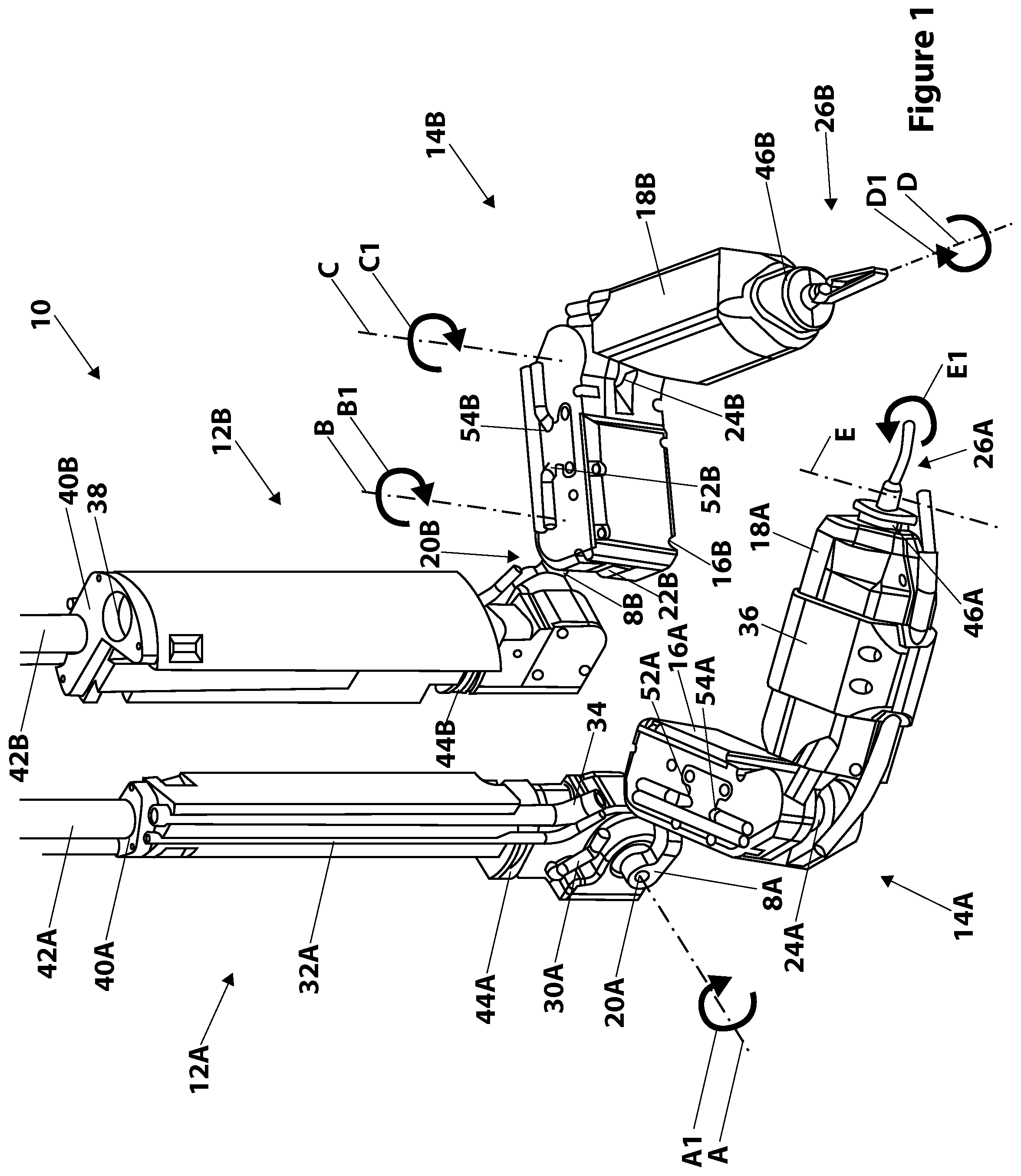
FIG. 1 is a diagram showing a robotic surgical system, including a robotic device positioned inside a body and axis of rotation, according to one embodiment.
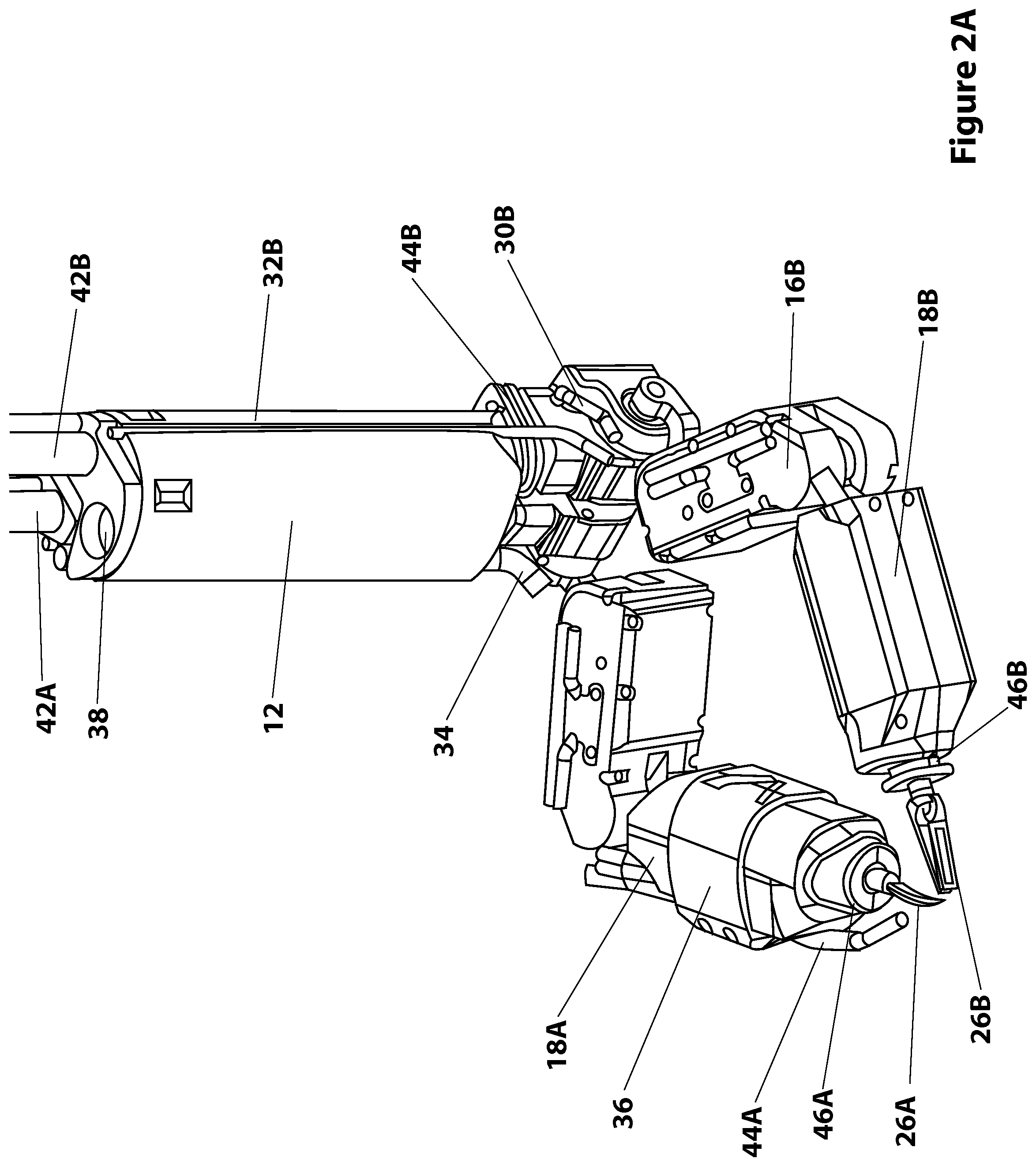
FIG. 2A is a perspective view of a robotic medical device, according to one embodiment.
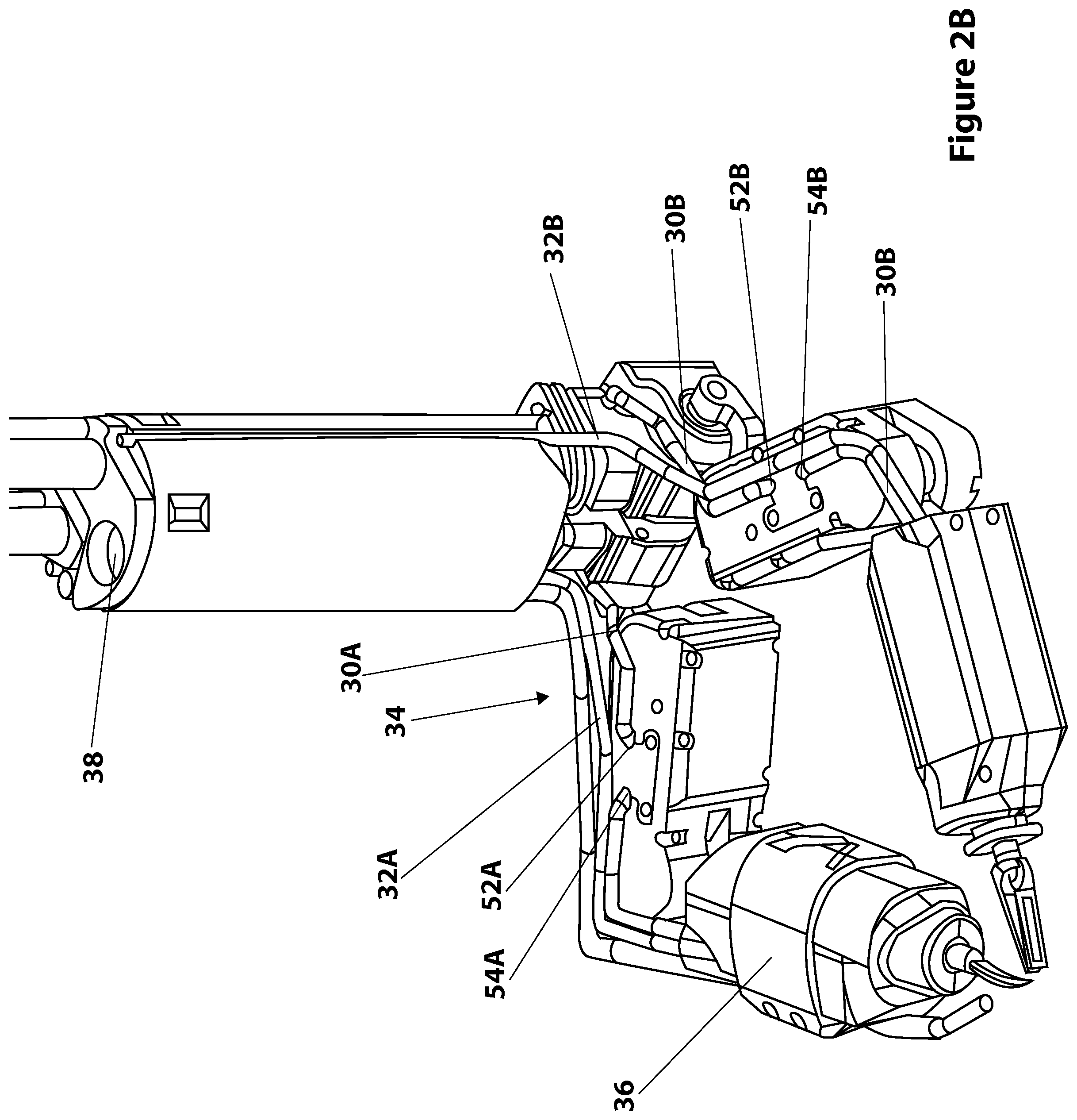
FIG. 2B is a perspective view of a robotic medical device, according to one embodiment.
FIG. 2C is a cut-away view of an arm of a robotic medical device, according to one embodiment.
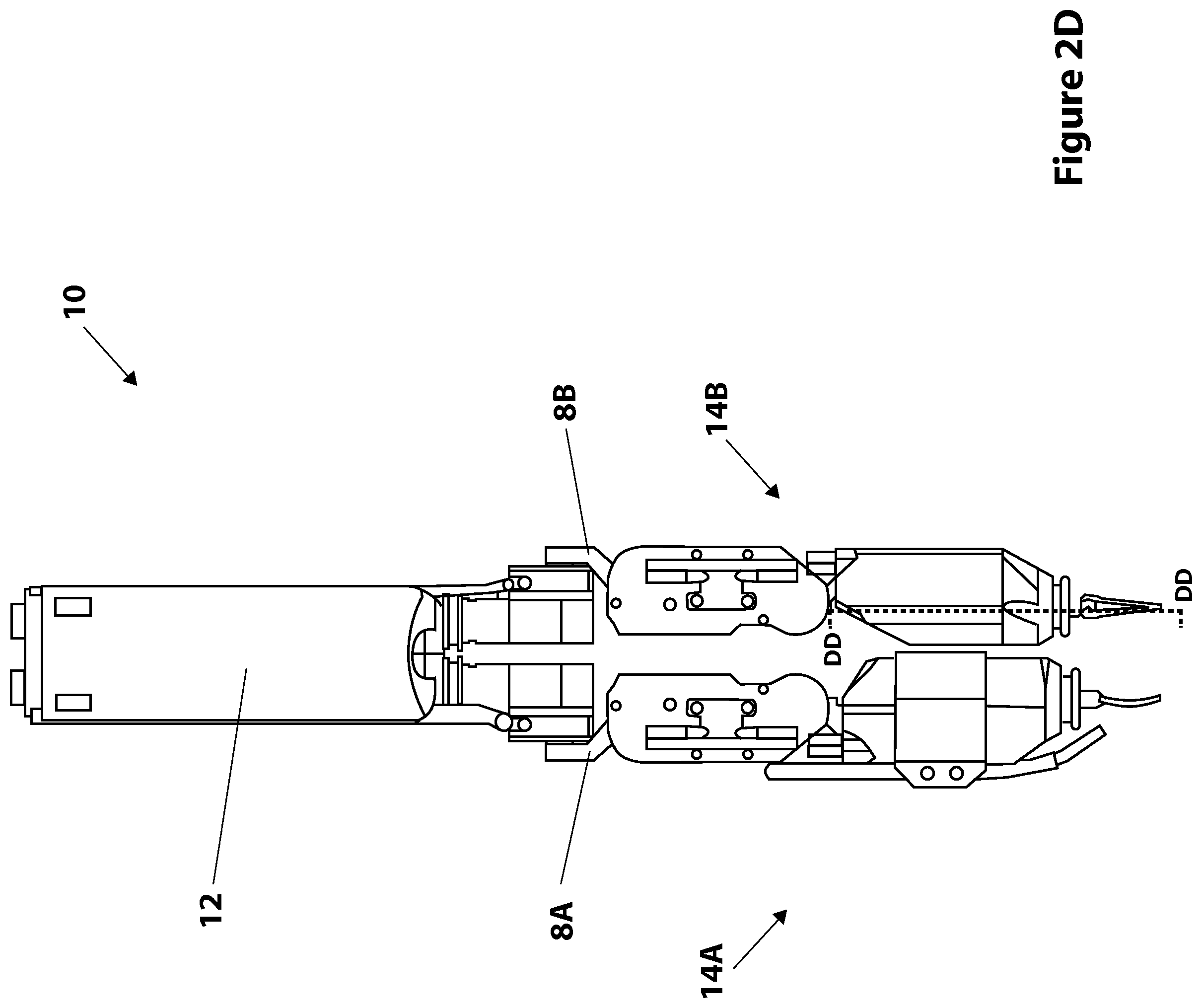
FIG. 2D is a sideview of a robotic medical device, according to one embodiment.
FIG. 3A is a perspective view of a body portion of a robotic device and related equipment, according to one embodiment.
FIG. 3B is a perspective view of another body portion of a robotic device and related equipment, according to one embodiment.
FIG. 4A is an endlong view of the body portion of a robotic device and related equipment, according to one embodiment.
FIG. 4B is a sideview of the body portion of a robotic device and related equipment, according to one embodiment.
FIG. 5A is a sideview of a body portion of a robotic device and related equipment, according to one embodiment.
FIG. 5B is a side cross-sectional view of a body portion of a robotic device and related equipment, according to one embodiment.
FIG. 5C is a perspective cross-sectional view of a body portion of a robotic device and related equipment, according to one embodiment.
FIG. 5D is a side cross-sectional view of a body portion of a robotic device and related equipment, according to one embodiment.
FIG. 6 is an endlong cross-sectional view of a body portion of a robotic device, according to one embodiment.
FIG. 7A is a cross-sectional sideview of the upper arm of a robotic device, according to one embodiment.
FIG. 7B is a cross-sectional sideview of the upper arm of a robotic device from an alternate view, according to one embodiment.
FIG. 7C is a perspective internal view of the upper arm of a robotic device, according to one embodiment.
FIG. 8A is a sideview of a forearm of a robotic device, according to one embodiment.
FIG. 8B is a cross-sectional view of a forearm of a robotic device, according to one embodiment.
FIG. 8C is another cross-sectional view of a forearm of a robotic device, according to one embodiment.
FIG. 8D is yet another cross-sectional view of a forearm of a robotic device, according to one embodiment.
FIG. 9A is cross-sectional sideview of the forearm of a robotic device, according to another embodiment.
FIG. 9B is another cross-sectional sideview of the forearm of a robotic device, according to another embodiment.
FIG. 10 is a perspective internal view of a forearm of a robotic device, according to another exemplary embodiment.
FIG. 11A contains a perspective view of an exemplary embodiment of the rotary slip ring assembly according to an exemplary embodiment.
FIG. 11B contains another perspective view of an exemplary embodiment of the rotary slip ring assembly the embodiment of FIG. 11A.
FIG. 11C is a cross sectional sideview of the rotary slip ring assembly the embodiment of FIG. 11A.
FIG. 11D is another cross-sectional sideview of the embodiment of FIG. 11A.
FIG. 11E is an endview of the embodiment of FIG. 11A.
FIG. 11F is another cross-sectional sideview of the embodiment of FIG. 11A, with associated components in the forearm.
FIG. 12A is a cutaway sideview of an exemplary embodiment of the surgical device forearm and tool assembly.
FIG. 12B is a side view of the tool assembly, according to an exemplary embodiment.
FIG. 13A is a perspective cutaway view of an exemplary embodiment of the surgical device forearm showing an embodiment of a linear encoder.
FIG. 13B is a cross-sectional sideview of the embodiment of a linear encoder according to FIG. 13A.
FIG. 13C is an end view of the embodiment of a linear encoder according to FIG. 13A and showing the cross section of FIG. 13B.
FIG. 13D is a sideview of the embodiment of a linear encoder according to FIG. 13A.
DETAILED DESCRIPTION
The various systems and devices disclosed herein relate to devices for use in medical procedures and systems. More specifically, various embodiments relate to various medical devices, including robotic devices and related methods and systems.
It is understood that the various embodiments of robotic devices and related methods and systems disclosed herein can be incorporated into or used with any other known medical devices, systems, and methods. For example, the various embodiments disclosed herein may be incorporated into or used with any of the medical devices and systems disclosed in copending U.S. application Ser. No. 11/766,683 (filed on Jun. 21, 2007 and entitled "Magnetically Coupleable Robotic Devices and Related Methods"), Ser. No. 11/766,720 (filed on Jun. 21, 2007 and entitled "Magnetically Coupleable Surgical Robotic Devices and Related Methods"), Ser. No. 11/966,741 (filed on Dec. 28, 2007 and entitled "Methods, Systems, and Devices for Surgical Visualization and Device Manipulation"), 61/030,588 (filed on Feb. 22, 2008), Ser. No. 12/171,413 (filed on Jul. 11, 2008 and entitled "Methods and Systems of Actuation in Robotic Devices"), Ser. No. 12/192,663 (filed Aug. 15, 2008 and entitled Medical Inflation, Attachment, and Delivery Devices and Related Methods"), Ser. No. 12/192,779 (filed on Aug. 15, 2008 and entitled "Modular and Cooperative Medical Devices and Related Systems and Methods"), Ser. No. 12/324,364 (filed Nov. 26, 2008 and entitled "Multifunctional Operational Component for Robotic Devices"), 61/640,879 (filed on May 1, 2012), Ser. No. 13/493,725 (filed Jun. 11, 2012 and entitled "Methods, Systems, and Devices Relating to Surgical End Effectors"), Ser. No. 13/546,831 (filed Jul. 11, 2012 and entitled "Robotic Surgical Devices, Systems, and Related Methods"), 61/680,809 (filed Aug. 8, 2012), Ser. No. 13/573,849 (filed Oct. 9, 2012 and entitled "Robotic Surgical Devices, Systems, and Related Methods"), and Ser. No. 13/738,706 (filed Jan. 10, 2013 and entitled "Methods, Systems, and Devices for Surgical Access and Insertion"), and U.S. Pat. No. 7,492,116 (filed on Oct. 31, 2007 and entitled "Robot for Surgical Applications"), U.S. Pat. No. 7,772,796 (filed on Apr. 3, 2007 and entitled "Robot for Surgical Applications"), and U.S. Pat. No. 8,179,073 (issued May 15, 2011, and entitled "Robotic Devices with Agent Delivery Components and Related Methods"), all of which are hereby incorporated herein by reference in their entireties.
Certain device and system implementations disclosed in the applications listed above can be positioned within a body cavity of a patient in combination with a support component similar to those disclosed herein. An "in vivo device" as used herein means any device that can be positioned, operated, or controlled at least in part by a user while being positioned within a body cavity of a patient, including any device that is coupled to a support component such as a rod or other such component that is disposed through an opening or orifice of the body cavity, also including any device positioned substantially against or adjacent to a wall of a body cavity of a patient, further including any such device that is internally actuated (having no external source of motive force), and additionally including any device that may be used laparoscopically or endoscopically during a surgical procedure. As used herein, the terms "robot," and "robotic device" shall refer to any device that can perform a task either automatically or in response to a command.
Certain embodiments provide for insertion of the present invention into the cavity while maintaining sufficient insufflation of the cavity. Further embodiments minimize the physical contact of the surgeon or surgical users with the present invention during the insertion process. Other implementations enhance the safety of the insertion process for the patient and the present invention. For example, some embodiments provide visualization of the present invention as it is being inserted into the patient's cavity to ensure that no damaging contact occurs between the system/device and the patient. In addition, certain embodiments allow for minimization of the incision size/length. Further implementations reduce the complexity of the access/insertion procedure and/or the steps required for the procedure. Other embodiments relate to devices that have minimal profiles, minimal size, or are generally minimal in function and appearance to enhance ease of handling and use.
Certain implementations disclosed herein relate to "combination" or "modular" medical devices that can be assembled in a variety of configurations. For purposes of this application, both "combination device" and "modular device" shall mean any medical device having modular or interchangeable components that can be arranged in a variety of different configurations. The modular components and combination devices disclosed herein also include segmented triangular or quadrangular-shaped combination devices. These devices, which are made up of modular components (also referred to herein as "segments") that are connected to create the triangular or quadrangular configuration, can provide leverage and/or stability during use while also providing for substantial payload space within the device that can be used for larger components or more operational components. As with the various combination devices disclosed and discussed above, according to one embodiment these triangular or quadrangular devices can be positioned inside the body cavity of a patient in the same fashion as those devices discussed and disclosed above.
As best shown in FIG. 1, in certain exemplary embodiments, the device 10 has two coupleable bodies 12A, 12B, each of which is rotatably coupled to one of two arms 14A, 14B as shown. The coupleable bodies 12A, 12B are also referred to as "shoulders," "shoulder assemblies," "connectors," and "connector assemblies." More specifically, each arm 14A, 14B has a coupling link 8A, 8B that couples the arm 14A, 14B to one of the coupleable bodies 12A, 12B. Each arm has an inner link (also referred to herein as an "inner arm," "inner arm assembly," "upper arm," "upper arm assembly," "first link," or "first link assembly") 16A, 16B and an outer link (also referred to herein as an "outer arm," "outer arm assembly," "forearm," "forearm assembly," "second link," or "second link assembly") 18A, 18B. The upper arms 16A, 16B are rotatably coupled to the coupling links 8A, 8B, which are rotatably coupled to the coupleable bodies 12A, 12B. In the right arm 14A, the upper arm 16A is rotatably coupled to the forearm 18A, while in the left arm 14B, the upper arm 16B is rotatably coupled to the forearm 18B.
Each of the arms 14A, 14B has five degrees of freedom. That is, each arm 14A, 14B has four rotatable joints or components and a single bipolar tool. For example, as best shown in FIGS. 1, 5A, and 5B, the coupling link 8A, 8B of each arm 14A, 14B has a rotatable joint 20A, 20B that is rotatable around an axis A that is perpendicular to the length of each of the coupleable bodies 12A, 12B, as shown by arrow A1. The rotatable joints 20A, 20B couple each of the coupleable bodies 12A, 12B to one of the coupling links 8A, 8B. This rotation around axis A is also called "shoulder pitch." FIGS. 5A and 5B depict the right coupleable body 12A. More specifically, FIG. 5A is a sideview of the right body 12A, while FIG. 5B is a cross-sectional cutaway view depicting the internal portion of the body 12A marked by line AA-AA in FIG. 5A. Further, FIG. 5B depicts axis A around which rotatable joint 20A rotates.
As best shown in FIGS. 1, 7A, and 7B, the coupling link 8A, 8B of each arm 14A, 14B also has a rotatable joint 22A, 22B that is rotatable around an axis B that is perpendicular to the axis A, as shown by arrow B1. FIGS. 7A and 7B depict the right upper arm 16A. More specifically, FIG. 7A is a top view of the right upper arm 16A, while FIG. 7B is a cross-section cutaway sideview depicted the internal portion of the upper arm 16A marked by line BB-BB in FIG. 7A. FIG. 7B also depicts axis B around which rotatable joint 22A rotates. The rotatable joints 22A, 22B couple the coupling links 8A, 8B to the upper arms 16A, 16B. This rotation around axis B is also called "shoulder yaw."
Also best depicted in FIGS. 1, 7A, and 7B, the arms 14A, 14B each have a rotatable joint 24A, 24B that is rotatable around an axis C that is parallel to axis B, as shown by arrow C1. FIG. 7B depicts axis C around which rotatable joint 24A rotates. The rotatable joints 24A, 24B couple the upper arms 16A, 16B to the forearms 18A, 18B. This rotation around axis C is also called "forearm yaw."
Additionally, as best shown in FIGS. 1 and 8B, each of the forearms 18A, 18B (or a portion thereof) are configured to rotate around an axis D that is perpendicular to axis C, as shown by arrow D1. This rotation allows for the rotation or "roll" of the end effectors 26A, 26B coupled to the distal end of each of the forearms 18A, 18B. This rotation around axis D is also called "end effector roll."
Further, as best shown in FIGS. 1 and 8A, each of the end effectors 26A, 26B, or, more specifically, certain components thereof, are configured to rotate or move around an axis E that is perpendicular to axis D, as shown by arrow E1. This rotation or movement allows for the opening and closing of the end effector 26A, 26B (also referred to as moving the end effector 26A, 26B between an open and closed position), such as a grasper or gripper or scissors. This rotation around axis E is also called "end effector opening/closing." FIG. 8A is a top view of the right forearm 18A, while FIG. 8B is a cross-section cutaway sideview depicted the internal portion of the forearm 18A marked by line CC-CC in FIG. 8A. FIG. 8A depicts axis E around which the end effector opening/closing occurs, while FIG. 8B depicts axis D around which the end effector roll occurs.
As best shown in FIGS. 1, 2A, 3A, 3B, 4A, and 4B, the two coupleable bodies 12A, 12B are configured to be coupled together. That is, each of the two bodies 12A, 12B have configurations that are mateable to each other such that the right body 12A can mate with and couple to the left body 12B such that the two bodies 12A, 12B form a single body 12. In one example, each of the bodies 12A, 12B have a matching coupling feature that allows the two bodies 12A, 12B to couple together such that they are retained in that coupled configuration. As shown in FIGS. 3A, 3B, 4A, and 4B, the right body 12A has a tapered notch 60 defined in one wall of the body 12A. The notch 60 is wider at the top of the notch 60 than it is at the bottom. Similarly, the left body 12B has a tapered projection 62 that is sized and configured to fit in the notch 60. The projection 62 is wider at the top of the projection 62 than it is at the bottom. In one embodiment, the two bodies 12A, 12B are coupled by positioning the left body 12B such that the bottom portion of the projection 62 can be slid into the top portion of the notch 60 and urged downward such that the projection 62 is positioned in the notch 60. When the projection 62 is correctly positioned in the notch 60, the two bodies 12A, 12B are mated correctly and the coupling is maintained by the mating of the notch 60 and projection 62. Alternatively, any other known mating or coupling feature or mechanism can be used. This coupleability of the two bodies 12A, 12B allows for the two bodies 12A, 12B to be coupled to each other prior to positioning the device 10 into the body or after the two arms 14A, 14B have been inserted into the target body cavity.
The upper arms 16A, 16B and the forearms 18A, 18B are operably coupled to an external controller (not shown) via electrical cables that transport both power and data. In certain embodiments, all six of the segments are operably coupled to such connection components (also referred to herein generally as "connection lines" or "connection components"), including both shoulders. In accordance with one implementation, two such connection components are provided, one for each arm. As best shown in FIG. 2B, in this embodiment the cables are bus power and communication lines 30A, 30B that are disposed in or coupled to the connector 12. The lines 30A, 30B transport power from an external power source (not shown) to the motors (not shown) disposed in the arm segments 16A, 16B, 18A, 18B and further transport data to and from the segments 16A, 16B, 18A, 18B to the controller. According to one embodiment, the proximal end of the lines 30A, 30B are operably coupled to an external source (not shown). According to one embodiment, the external source is an external controller that is a power supply and a communication port. Alternatively, the power supply and the controller can be separate external components. At their distal ends, the power and communication lines 30A, 30B are operably coupled to the microcontrollers and the motors in the arms 14A, 14B as well as the microcontrollers and motors in the shoulders. More specifically, as shown in FIGS. 1 and 2B, the right line 30A extends from the right connector 12A to the right upper arm 16A and is positioned through a hole 52A formed in a top portion of the upper arm 16A. In the upper arm 16A, the line 30A is operably coupled to the at least one microcontroller and the at least one motor (not shown) in the arm 16A. From the upper arm 16A, the line 30A extends out of a hole 54A and to the forearm 18A, where the line 30A is coupled to the at least one microcontroller and the at least one motor (not shown) in the forearm 18A.
Similarly, as also shown in FIGS. 1 and 2B, the left line 30B extends from the left connector 12B to the left upper arm 16B and is positioned through a hole 52B formed in a top portion of the upper arm 16B. In the upper arm 16B, the line 30B is operably coupled to the at least one microcontroller and the at least one motor (not shown) in the arm 16B. From the upper arm 16B, the line 30B extends out of a hole 54B and to the forearm 18B, where the line 30B is coupled to the at least one microcontroller and the at least one motor (not shown) in the forearm 18B. In certain embodiments, the lines 30A, 30B are reinforced or mechanically strain-relieved at the access points to the arm segments (such as holes 52A, 52B, 54A, 54B) to minimize or eliminate damage to the lines 30A, 30B caused by strain as a result of the movement of the arms 14A, 14B. Additionally the lines 30 A, 30B are sealed at the access points to prevent fluid ingress into the robot.
As best shown in FIGS. 1, 2A, and 2B, two cautery lines 32A, 32B are also disposed in or coupled to the connector 12A, 12B. In this depicted embodiment, the right cautery line 32A is attached to an exterior portion of the right connector 12A (as best shown in FIG. 1), while the left cautery line 32B is attached to an exterior portion of the left connector 12B (as best shown in FIGS. 2A and 2B). The proximal ends of the lines 32A, 32B are coupled to an external power source (not shown). As best shown in FIG. 2B, the right cautery line 32A extends from the right connector 12A to the right forearm 18A, in which the line 32A is operably coupled to the end effector 26A. In one implementation, the portion of the line 32A that extends from the connector 12A to the forearm 18A is coupled to an exterior portion of the upper arm 16A as shown. Alternatively, the line 32A could extend through an interior portion of the upper arm 16A. Similarly, the left cautery line 32B extends from the left connector 12B to the left forearm 18B, in which the line 32B is operably coupled to the end effector 26B. In one implementation, the portion of the line 32B that extends from the connector 12B to the forearm 18B is coupled to an exterior portion of the upper arm 16B as shown. Alternatively, the line 32B could extend through an interior portion of the upper arm 16B.
As best shown in FIGS. 1 and 2B, a dual suction/irrigation line 34A, 34B is also coupled to the connector 12. The dual line 34A, 34B is a known line that is comprised of at least one line that can be alternatively used for suction or irrigation. In certain other embodiments, more than one line can be provided, thus providing for suction and irrigation. In the embodiment depicted in FIGS. 1 and 2B, at its proximal end, the dual suction/irrigation line 34 is coupled to an external irrigation/suction component (not shown) that provides suction or irrigation to the lumen. In one embodiment, the line 34A, 34B is coupled at its proximal end to a valve having two separate lines: one line extending to a known suction device and the other line extending to a known irrigation device. This commercially-available valve is known generally as a "trumpet valve." Alternatively, the dual line 34A, 34B is coupled to any known external component that provides suction and irrigation, or is coupled to two separate devices, one providing suction and the other providing irrigation. Alternatively, it is understood that two separate lines can be provided--a suction line and an irrigation line. In this embodiment, the dual suction/irrigationline 34A is coupled to an exterior portion of the right connector 12A. The suction/irrigation line 34A extends from the right connector 12A to the right arm 14A, where the line 34A is coupled to an exterior portion of the upper arm 16A and to an exterior portion of the forearm 18A as shown.
In one embodiment, the forearm 18A has an attachment component 36 configured to couple the suction/irrigation line 34 to the forearm 18A. In this particular exemplary embodiment, the attachment component 36 is an attachment collar 36 configured to be positioned around the forearm 18A and coupled to the line 34 such that the collar 36 helps to keep the line 34 coupled to the forearm 18A. At its distal end, the dual suction/irrigation line 34 is operably coupled to the cautery scissors 26A.
As shown in FIGS. 2A and 2B, the connector 12 has a laparoscope lumen 38 defined in the connector 12. The lumen 38 is configured to receive any standard laparoscopic imaging device. Further, each of the two coupleable connectors 12A, 12B defines an insertion rod lumen 40A, 40B. Each lumen 40A, 40B is configured to receive an insertion rod 42A, 42B.
In accordance with one implementation, each of the power and communications lines 30A, 30B, the cautery lines 32A, 32B, and the dual suction/irrigation line 34 are all coupled with or disposed in the connector 12 such that a seal is maintained between the connector 12 and the access port (not shown) mounted to the patient. That is, as best shown in FIG. 6, the connector 12 (and the two connector bodies 12A, 12B), according to one embodiment, has grooves or channels 70 defined along the outer surface of the two bodies 12A, 12B such that the various lines and cables (including the power and communications lines 30A, 30B, the cautery lines 32A, 32B, the suction/irrigation line 34, and any other lines or cables that might be incorporated into the device) are positioned in those grooves or channels 70. The positioning of the lines or cables in the grooves or channels 70 helps to maintain a smooth outer perimeter around the outer surface of the connector 12, thereby ensuring a successful fluidic seal with the access port when the connector 12 is positioned therethrough. It is understood that the access port can be any known port for use with laparoscopic surgical tools, including the port devices described in U.S. patent application Ser. No. 13/738,706, filed on Jan. 10, 2013, which is hereby incorporated herein by reference in its entirety. In certain exemplary embodiments, the access port can be readily removed, cleaned and sterilized.
According to one implementation, the arms 14A, 14B are configured to receive a fluid sealing component over the arms 14A, 14B. That is, as best shown in FIG. 1, each of the coupleable connectors 12A, 12B, has a channel 44A, 44B defined around the connectors 12A, 12B and each of the arms 14A, 14B has a channel 46A, 46B defined around a distal portion of the forearms 18A, 18B. Fluid sealing protective sleeves (not shown), such as those, for example, described in U.S. application Ser. No. 13/573,849, filed on Oct. 9, 2012, which is hereby incorporated by reference herein in its entirety, are positioned over each arm 14A, 14B and the ends of each sleeve are positioned in one of the channels 44A, 44B, 46A, 46B such that the sleeves are coupled to the arms 14A, 14B such that the sleeves create a fluidic seal around each arm 14A, 14B, whereby moisture and liquid are prevented from ingressing into the arms 14A, 14B.
Each of the joints described above is operably coupled to a motor via a geartrain (not shown). Further, each joint is also operably coupled to a microcontroller. In addition, each joint is operably coupled to at least one position sensor. According to one embodiment, each joint is coupled to both a relative position sensor and an absolute position sensor. According to another embodiment, each joint has at least a relative position sensor.
As best shown in FIGS. 2C and 2D, the configuration of the connector 12 and the arms 14A, 14B in this embodiment provide a minimal cross-sectional area for the device 10, thereby allowing for easy insertion of the device 10 through a small incision and into a small cavity of a patient. That is, the coupling of the arms 14A, 14B to the connector 12 via the coupling links 8A, 8B, along with the ability to position the arms 14A, 14B as shown in FIGS. 2C and 2D, results in a narrower device 10 that can fit through smaller incisions in comparison to devices that are wider/have larger cross-sections. In use, the arms 14A, 14B of the device 10 can be positioned as shown in these figures prior to insertion into a patient's cavity. The device 10 can then be positioned through an incision in a single linear motion. In one embodiment, the device 10 is inserted one arm at a time. That is, the two coupleable bodies 12A, 12B with arms attached are positioned in the patient's cavity prior to coupling the two bodies 12A, 12B together. Alternatively, the device 10 is inserted as a single unit, with the two bodies 12A, 12B already coupled together.
FIGS. 5C and 5D depict a close-up of the right connector 12A, according to one embodiment. It is understood that the internal components of the right connector 12A as described herein are substantially similar to the equivalent components in the left connector 12B, so the following description shall encompass those equivalent components as well. As best shown in FIG. 5D, the right connector 12A has a connector motor 160 that is operably coupled to a bevel motor gear 162. The bevel motor gear 162 is operably coupled to a bevel driven gear 164, which constitutes joint 20A discussed above. The drive gear 164 is supported in this embodiment by two bearings 166 and is operably coupled to the right coupling link 8A, which is also described above. In one implementation, a magnetic absolute position encoder 168 (also shown in FIG. 5C) and an encoder magnet 170 are operably coupled to the driven gear 164, and are thereby configured to provide information about the position of the gear 164. As best shown in FIG. 5C, a motor control board 172 is positioned in the housing of the connector 12A.
In accordance with one embodiment, the right and left upper arms 16A, 16B, including the coupling links 8A, 8B, have configurations that are identical or substantially similar and are simply minor versions of each other. Alternatively, they can have some different components as necessary for the specific end effectors that might be coupled to the forearms 18A, 18B.
FIGS. 7A, 7B, and 7C depict a right upper arm 16A, according to one embodiment. It is understood that the internal components of the right upper arm 16A as described herein are substantially similar to the equivalent components in the left upper arm 16B, so the following description shall encompass those equivalent components as well. The upper arm 16A has two motors 200, 202. The first motor 200 is configured to actuate the shoulder shaft 204 to rotate in relation to the coupling link 8A, thereby rotating around axis B. The second motor 202 is configured to actuate the elbow shaft 206 to rotate in relation to the forearm 18A, thereby rotating around axis C.
As best shown in FIG. 7B, the first motor 200 is operably coupled to motor gear 208, which is operably coupled to the driven gear 210. The driven gear 210 is operably coupled to the shoulder shaft 204 such that rotation of the driven gear 210 causes rotation of the shoulder shaft 204. The shaft 204 is supported by bearings 216A, 216B. The motor 202 is operably coupled to motor gear 212, which is operably coupled to the driven gear 214. The driven gear 214 is operably coupled to the elbow shaft 206 such that rotation of the driven gear 214 causes rotation of the elbow shaft 206. The shaft 206 is supported by bearings 218A, 218B.
Each of the shafts 204, 206 is operably coupled to an encoder magnet 222A, 222B, each of which is operably coupled to an absolute position magnetic encoder 220A, 220B. The encoders 220A, 220B work in a fashion similar to the position encoders described above. At least one motor control board 224 is positioned in the housing of the upper arm 16A as best shown in FIG. 7C.
In contrast, in this implementation as shown in FIGS. 1 and 2A, the right and left forearms 18A, 18B are not identical. That is, the right forearm 18A has an end effector 26A further comprising cautery scissors 26A. According to one embodiment, the cautery scissors 26A is a "quick-change" mono-polar cautery scissors 26A. That is, the cautery scissors 26A can be coupled to or removed from the forearm 18A without t
References
D00000
D00001
D00002
D00003
D00004
D00005
D00006
D00007
D00008
D00009
D00010
D00011
D00012
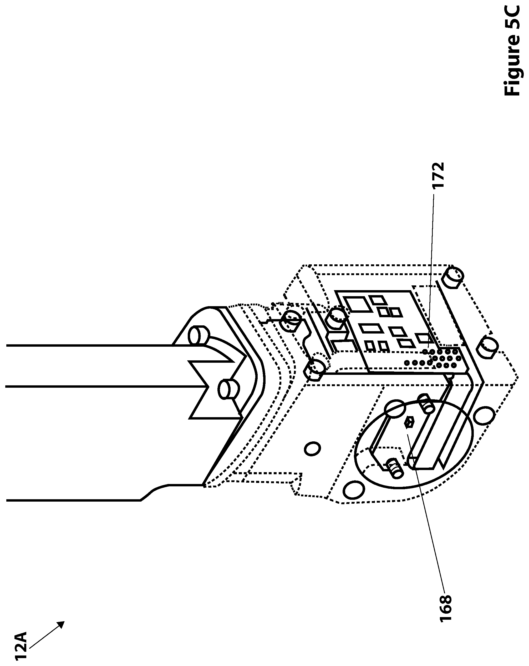
D00013

D00014

D00015

D00016

D00017
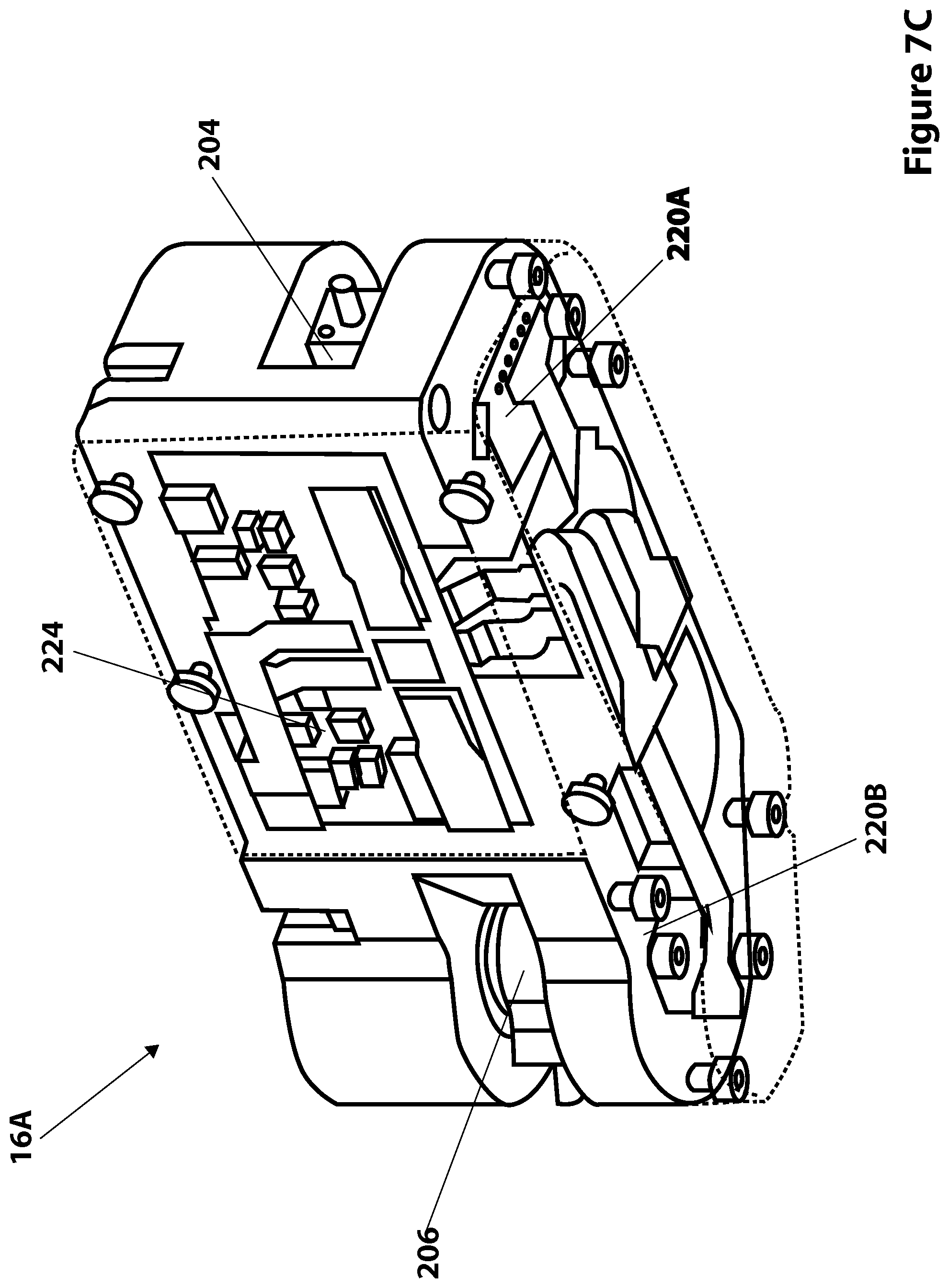
D00018

D00019

D00020

D00021

D00022

D00023

D00024

D00025

D00026

D00027

D00028

D00029

D00030

D00031

D00032

D00033
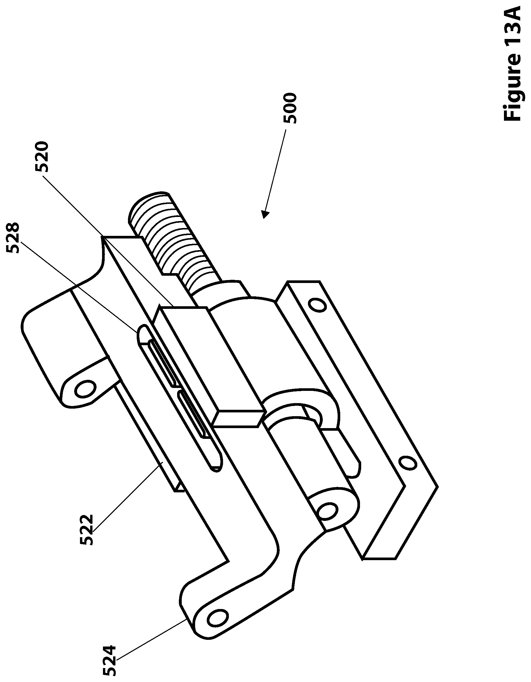
D00034

D00035

D00036

XML
uspto.report is an independent third-party trademark research tool that is not affiliated, endorsed, or sponsored by the United States Patent and Trademark Office (USPTO) or any other governmental organization. The information provided by uspto.report is based on publicly available data at the time of writing and is intended for informational purposes only.
While we strive to provide accurate and up-to-date information, we do not guarantee the accuracy, completeness, reliability, or suitability of the information displayed on this site. The use of this site is at your own risk. Any reliance you place on such information is therefore strictly at your own risk.
All official trademark data, including owner information, should be verified by visiting the official USPTO website at www.uspto.gov. This site is not intended to replace professional legal advice and should not be used as a substitute for consulting with a legal professional who is knowledgeable about trademark law.