Agricultural planting system with automatic depth control
Bassett
U.S. patent number 10,582,653 [Application Number 15/856,875] was granted by the patent office on 2020-03-10 for agricultural planting system with automatic depth control. This patent grant is currently assigned to Dawn Equipment Company. The grantee listed for this patent is Dawn Equipment Company. Invention is credited to Joseph D. Bassett.


View All Diagrams
| United States Patent | 10,582,653 |
| Bassett | March 10, 2020 |
Agricultural planting system with automatic depth control
Abstract
A control system for controlling the depth of an opener device in an agricultural planter comprises a gauge wheel on a pivotably mounted support arm, a mechanical element coupled to the support arm to move in response to changes in the angle of the support arm, a sensor adapted to measure changes in the relative elevations of the opener device and the gauge wheel to produce an output signal representing the current relative elevations of the opener device and the gauge wheel, and a control device receiving the output signal from the sensor and producing a second output signal for maintaining the opener device at a selected elevation relative to the gauge wheel.
| Inventors: | Bassett; Joseph D. (Sycamore, IL) | ||||||||||
|---|---|---|---|---|---|---|---|---|---|---|---|
| Applicant: |
|
||||||||||
| Assignee: | Dawn Equipment Company
(Sycamore, IL) |
||||||||||
| Family ID: | 62019720 | ||||||||||
| Appl. No.: | 15/856,875 | ||||||||||
| Filed: | December 28, 2017 |
Prior Publication Data
| Document Identifier | Publication Date | |
|---|---|---|
| US 20180116098 A1 | May 3, 2018 | |
Related U.S. Patent Documents
| Application Number | Filing Date | Patent Number | Issue Date | ||
|---|---|---|---|---|---|
| 15637692 | Jun 29, 2017 | ||||
| 14858089 | Dec 26, 2017 | 9848522 | |||
| 62085334 | Nov 28, 2014 | ||||
| 62076767 | Nov 7, 2014 | ||||
| Current U.S. Class: | 1/1 |
| Current CPC Class: | A01C 5/062 (20130101); A01C 5/04 (20130101); A01B 63/111 (20130101); A01C 5/064 (20130101); A01B 63/24 (20130101); A01C 7/205 (20130101) |
| Current International Class: | A01B 63/111 (20060101); A01C 7/20 (20060101); A01B 63/24 (20060101); A01C 5/04 (20060101); A01C 5/06 (20060101) |
References Cited [Referenced By]
U.S. Patent Documents
| 114002 | April 1871 | Godfrey |
| 123966 | February 1872 | Wing |
| 321906 | July 1885 | McCormick |
| 353491 | February 1886 | Wells |
| 523508 | July 1894 | Bauer |
| 736369 | August 1903 | Dynes |
| 803088 | October 1905 | Barker |
| 1069264 | August 1913 | Keller |
| 1134462 | April 1915 | Kendrick |
| 1158023 | October 1915 | Beaver |
| 1247744 | November 1917 | Trimble |
| 1260752 | March 1918 | Casaday |
| 1321040 | November 1919 | Hoffman |
| 1391593 | September 1921 | Sweeting |
| 1398668 | November 1921 | Bordsen |
| 1481981 | January 1924 | Boye |
| 1791462 | February 1931 | Bermel |
| 1844255 | February 1932 | Kaupke |
| 1901299 | March 1933 | Johnson |
| 1901778 | March 1933 | Schlag |
| 1938132 | December 1933 | Broemmelsick |
| 2014334 | September 1935 | Johnson |
| 2058539 | October 1936 | Welty |
| 2249637 | July 1941 | Rietz |
| 2269051 | January 1942 | Cahoy |
| 2285932 | June 1942 | Leavitt |
| 2298539 | October 1942 | Mott |
| 2341143 | February 1944 | Herr |
| 2505276 | April 1950 | Boroski |
| 2561763 | July 1951 | Waters |
| 2593176 | April 1952 | Patterson |
| 2596527 | May 1952 | Bushong |
| 2611306 | September 1952 | Strehlow |
| 2612827 | October 1952 | Baggette |
| 2664040 | December 1953 | Beard |
| 2691353 | October 1954 | Secondo |
| 2692544 | October 1954 | Jessup |
| 2715286 | August 1955 | Saveson |
| 2754622 | July 1956 | Rohnert |
| 2771044 | November 1956 | Putifer |
| 2773343 | December 1956 | Oppel |
| 2777373 | January 1957 | Pursche |
| 2799234 | July 1957 | Chancey |
| 2805574 | September 1957 | Jackson, Jr. |
| 2860716 | November 1958 | Flock |
| 2925872 | February 1960 | Darnell |
| 2960358 | November 1960 | Christison |
| 3010744 | November 1961 | Hollis |
| 3014547 | December 1961 | Van der Lely |
| 3038424 | June 1962 | Johnson |
| 3042121 | July 1962 | Broetzman |
| 3057092 | October 1962 | Curlett |
| 3058243 | October 1962 | McGee |
| 3065879 | November 1962 | Jennings |
| 3080004 | March 1963 | McNair |
| 3103993 | September 1963 | Gies |
| 3110973 | November 1963 | Reynolds |
| 3122901 | March 1964 | Thompson |
| 3123152 | March 1964 | Biskis |
| 3188989 | June 1965 | Johnston |
| 3213514 | October 1965 | Evans |
| 3250109 | May 1966 | Spyridakis |
| 3256942 | June 1966 | Van Sickle |
| 3314278 | April 1967 | Bergman |
| 3319589 | May 1967 | Moran |
| 3351139 | November 1967 | Schmitz |
| 3355930 | December 1967 | Fedorov |
| 3368788 | February 1968 | Padula |
| 3368789 | February 1968 | Martin |
| 3370450 | February 1968 | Scheucher |
| 3397933 | August 1968 | Hatcher |
| 3420273 | January 1969 | Greer |
| 3433474 | March 1969 | Piret |
| 3447495 | June 1969 | Miller |
| 3500937 | March 1970 | Erickson |
| 3507233 | April 1970 | Greig |
| 3539020 | November 1970 | Andersson |
| 3543603 | December 1970 | Gley |
| 3561541 | February 1971 | Woelfel |
| 3576098 | April 1971 | Brewer |
| 3581685 | June 1971 | Taylor |
| 3593720 | July 1971 | Botterill |
| D221461 | August 1971 | Hagenstad |
| 3606745 | September 1971 | Girodat |
| 3635495 | January 1972 | Orendorff |
| 3650334 | March 1972 | Hagenstad |
| 3653446 | April 1972 | Kalmon |
| 3701327 | October 1972 | Krumholz |
| 3708019 | January 1973 | Ryan |
| 3711974 | January 1973 | Webb |
| 3718191 | February 1973 | Williams |
| 3749035 | July 1973 | Cayton |
| 3753341 | August 1973 | Berg, Jr. |
| 3766988 | October 1973 | Whitesides |
| 3774446 | November 1973 | Diehl |
| 3795291 | March 1974 | Naito |
| 3906814 | September 1975 | Magnussen |
| 3939846 | February 1976 | Drozhzhin |
| 3945532 | March 1976 | Marks |
| 3975890 | August 1976 | Rodger |
| 3986464 | October 1976 | Uppiano |
| 4009668 | March 1977 | Brass |
| 4018101 | April 1977 | Mihalic |
| 4044697 | August 1977 | Swanson |
| 4055126 | October 1977 | Brown |
| 4058171 | November 1977 | Van der Lely |
| 4063597 | December 1977 | Day |
| 4069029 | January 1978 | Hudson |
| 4096730 | June 1978 | Martin |
| 4099576 | July 1978 | Jilani |
| 4122715 | October 1978 | Yokoyama |
| 4129082 | December 1978 | Betulius |
| 4141200 | February 1979 | Johnson |
| 4141302 | February 1979 | Morrison, Jr. |
| 4141676 | February 1979 | Jannen |
| 4142589 | March 1979 | Schlagenhauf |
| 4147305 | April 1979 | Hunt |
| 4149475 | April 1979 | Bailey |
| 4157661 | June 1979 | Schindel |
| 4161090 | July 1979 | Watts, Jr. |
| 4173259 | November 1979 | Heckenkamp |
| 4182099 | January 1980 | Davis |
| 4187916 | February 1980 | Harden |
| 4191262 | March 1980 | Sylvester |
| 4194575 | March 1980 | Whalen |
| 4196567 | April 1980 | Davis |
| 4196917 | April 1980 | Oakes |
| 4206817 | June 1980 | Bowerman |
| 4208974 | June 1980 | Dreyer |
| 4213408 | July 1980 | West |
| 4225191 | September 1980 | Knoski |
| 4233803 | November 1980 | Davis |
| 4241674 | December 1980 | Mellinger |
| 4249613 | February 1981 | Scribner |
| 4280419 | July 1981 | Fischer |
| 4295532 | October 1981 | Williams |
| 4301870 | November 1981 | Carre |
| 4307674 | December 1981 | Jennings |
| 4311104 | January 1982 | Steilen |
| 4317355 | March 1982 | Hatsuno |
| 4359101 | November 1982 | Gagnon |
| 4375837 | March 1983 | van der Lely |
| 4377979 | March 1983 | Peterson |
| 4391335 | July 1983 | Birkenbach |
| 4398608 | August 1983 | Boetto |
| 4407371 | October 1983 | Hohl |
| 4407660 | October 1983 | Nevens |
| 4413685 | November 1983 | Gremelspacher |
| 4430952 | February 1984 | Murray |
| 4433568 | February 1984 | Kondo |
| 4438710 | March 1984 | Paladino |
| 4445445 | May 1984 | Sterrett |
| 4461355 | July 1984 | Peterson |
| 4481830 | November 1984 | Smith |
| 4499775 | February 1985 | Lasoen |
| 4506610 | March 1985 | Neal |
| 4508178 | April 1985 | Cowell |
| 4528920 | July 1985 | Neumeyer |
| 4530405 | July 1985 | White |
| 4537262 | August 1985 | van der Lely |
| 4538688 | September 1985 | Szucs |
| 4550122 | October 1985 | David |
| 4553607 | November 1985 | Behn |
| 4580506 | April 1986 | Fleischer |
| 4596200 | June 1986 | Gafford |
| 4598654 | July 1986 | Robertson |
| 4603746 | August 1986 | Swales |
| 4604906 | August 1986 | Scarpa |
| 4619329 | October 1986 | Gorbett |
| 4630773 | December 1986 | Ortlip |
| 4643043 | February 1987 | Furuta |
| 4646620 | March 1987 | Buchl |
| 4646850 | March 1987 | Brown |
| 4648466 | March 1987 | Baker |
| 4650005 | March 1987 | Tebben |
| 4669550 | June 1987 | Sittre |
| 4671193 | June 1987 | States |
| 4674578 | June 1987 | Bexten |
| 4682550 | July 1987 | Joy |
| 4703809 | November 1987 | Van den Ende |
| 4726304 | February 1988 | Dreyer |
| RE32644 | April 1988 | Brundage |
| 4738461 | April 1988 | Stephenson |
| 4744316 | May 1988 | Lienemann |
| 4762075 | August 1988 | Halford |
| 4765190 | August 1988 | Strubbe |
| 4768387 | September 1988 | Kemp |
| 4776404 | October 1988 | Rogers |
| 4779684 | October 1988 | Schultz |
| 4785890 | November 1988 | Martin |
| 4819738 | April 1989 | Fountain |
| 4825957 | May 1989 | White |
| 4825959 | May 1989 | Wilhelm |
| 4920901 | May 1990 | Pounds |
| 4926767 | May 1990 | Thomas |
| 4930431 | June 1990 | Alexander |
| 4986367 | January 1991 | Kinzenbaw |
| 4987841 | January 1991 | Rawson |
| 4998488 | March 1991 | Hansson |
| 5015997 | May 1991 | Strubbe |
| 5022333 | June 1991 | McClure |
| 5027525 | July 1991 | Haukaas |
| 5033397 | July 1991 | Colburn, Jr. |
| 5065632 | November 1991 | Reuter |
| 5074227 | December 1991 | Schwitters |
| 5076180 | December 1991 | Schneider |
| 5092255 | March 1992 | Long |
| 5113957 | May 1992 | Tamai |
| 5129282 | July 1992 | Bassett |
| 5136934 | August 1992 | Darby, Jr. |
| 5190112 | March 1993 | Johnston |
| 5224553 | July 1993 | Heintzman |
| 5234060 | August 1993 | Carter |
| 5240080 | August 1993 | Bassett |
| 5255617 | October 1993 | Williams |
| 5269237 | December 1993 | Baker |
| 5282389 | February 1994 | Faivre |
| 5285854 | February 1994 | Thacker |
| 5333694 | August 1994 | Roggenbuck |
| 5337832 | August 1994 | Bassett |
| 5341754 | August 1994 | Winterton |
| 5346019 | September 1994 | Kinzenbaw |
| 5346020 | September 1994 | Bassett |
| 5349911 | September 1994 | Holst |
| 5351635 | October 1994 | Hulicsko |
| 5379847 | January 1995 | Snyder |
| 5394946 | March 1995 | Clifton |
| 5398771 | March 1995 | Hornung |
| 5419402 | May 1995 | Heintzman |
| 5427192 | June 1995 | Stephenson |
| 5443023 | August 1995 | Carroll |
| 5443125 | August 1995 | Clark |
| 5461995 | October 1995 | Winterton |
| 5462124 | October 1995 | Rawson |
| 5473999 | December 1995 | Rawson |
| 5474135 | December 1995 | Schlagel |
| 5477682 | December 1995 | Tobiasz |
| 5477792 | December 1995 | Bassett |
| 5479868 | January 1996 | Bassett |
| 5479992 | January 1996 | Bassett |
| 5485796 | January 1996 | Bassett |
| 5485886 | January 1996 | Bassett |
| 5497717 | March 1996 | Martin |
| 5497837 | March 1996 | Kehrney |
| 5499042 | March 1996 | Yanagawa |
| 5499683 | March 1996 | Bassett |
| 5499685 | March 1996 | Downing, Jr. |
| 5517932 | May 1996 | Ott |
| 5524525 | June 1996 | Nikkel |
| 5531171 | July 1996 | Whitesel |
| 5542362 | August 1996 | Bassett |
| 5544709 | August 1996 | Lowe |
| 5562165 | October 1996 | Janelle |
| 5590611 | January 1997 | Smith |
| 5603269 | February 1997 | Bassett |
| 5623997 | April 1997 | Rawson |
| 5640914 | June 1997 | Rawson |
| 5657707 | August 1997 | Dresher |
| 5660126 | August 1997 | Freed |
| 5685245 | November 1997 | Bassett |
| 5704430 | January 1998 | Smith |
| 5709271 | January 1998 | Bassett |
| 5725057 | March 1998 | Taylor |
| 5727638 | March 1998 | Wodrich |
| 5730074 | March 1998 | Peter |
| 5809757 | September 1998 | McLean |
| 5852982 | December 1998 | Peter |
| 5868207 | February 1999 | Langbakk |
| 5878678 | March 1999 | Stephens |
| RE36243 | July 1999 | Rawson |
| 5953895 | September 1999 | Hobbs |
| 5970891 | October 1999 | Schlagel |
| 5970892 | October 1999 | Wendling |
| 5988293 | November 1999 | Brueggen |
| 6067918 | May 2000 | Kirby |
| 6068061 | May 2000 | Smith |
| 6079340 | June 2000 | Flamme |
| 6082274 | July 2000 | Peter |
| 6085501 | July 2000 | Walch |
| 6091997 | July 2000 | Flamme |
| 6164385 | December 2000 | Buchl |
| 6176334 | January 2001 | Lorenzen |
| 6223663 | May 2001 | Wendling |
| 6223828 | May 2001 | Paulson |
| 6237696 | May 2001 | Mayerle |
| 6253692 | July 2001 | Wendling |
| 6289829 | September 2001 | Fish |
| 6295939 | October 2001 | Emms |
| 6314897 | November 2001 | Hagny |
| 6325156 | December 2001 | Barry |
| 6330922 | December 2001 | King |
| 6331142 | December 2001 | Bischoff |
| 6343661 | February 2002 | Thomspon |
| 6347594 | February 2002 | Wendling |
| 6382326 | May 2002 | Goins |
| 6389999 | May 2002 | Duello |
| 6453832 | September 2002 | Schaffert |
| 6454019 | September 2002 | Prairie |
| 6460623 | October 2002 | Knussman |
| 6516595 | February 2003 | Rhody |
| 6530334 | March 2003 | Hagny |
| 6575104 | June 2003 | Brummelhuis |
| 6622468 | September 2003 | Lucand |
| 6644224 | November 2003 | Bassett |
| 6681868 | January 2004 | Kovach |
| 6701856 | March 2004 | Zoke |
| 6701857 | March 2004 | Jensen |
| 6715433 | April 2004 | Friestad |
| 6763773 | July 2004 | Schaffert |
| 6786130 | September 2004 | Steinlage |
| 6827029 | December 2004 | Wendte |
| 6834598 | December 2004 | Juptner |
| 6840853 | January 2005 | Foth |
| 6886650 | May 2005 | Bremmer |
| 6889943 | May 2005 | Dinh |
| 6892656 | May 2005 | Schneider |
| 6907833 | June 2005 | Thompson |
| 6912963 | July 2005 | Bassett |
| 6923390 | August 2005 | Barker |
| 6968907 | November 2005 | Raper |
| 6986313 | January 2006 | Halford |
| 6997400 | February 2006 | Hanna |
| 7004090 | February 2006 | Swanson |
| 7044070 | May 2006 | Kaster |
| 7063167 | June 2006 | Staszak |
| 7159523 | January 2007 | Bourgault |
| 7163227 | January 2007 | Burns |
| 7222575 | May 2007 | Bassett |
| 7290491 | November 2007 | Summach |
| 7325756 | February 2008 | Giorgis |
| 7360494 | April 2008 | Martin |
| 7360495 | April 2008 | Martin |
| 7438006 | October 2008 | Mariman |
| 7451712 | November 2008 | Bassett |
| 7497174 | March 2009 | Sauder |
| 7523709 | April 2009 | Kiest |
| 7540333 | June 2009 | Bettin |
| 7575066 | August 2009 | Bauer |
| 7584707 | September 2009 | Sauder |
| 7665539 | February 2010 | Bassett |
| 7673570 | March 2010 | Bassett |
| 7743718 | June 2010 | Bassett |
| 7870827 | January 2011 | Bassett |
| 7918285 | April 2011 | Graham |
| 7938074 | May 2011 | Liu |
| 7944210 | May 2011 | Fischer |
| 7946231 | May 2011 | Martin |
| 7975629 | July 2011 | Martin |
| 8146519 | April 2012 | Bassett |
| 8151717 | April 2012 | Bassett |
| 8171707 | May 2012 | Kitchel |
| D663326 | July 2012 | Allensworth |
| 8327780 | December 2012 | Bassett |
| 8359988 | January 2013 | Bassett |
| 8380356 | February 2013 | Zielke |
| 8386137 | February 2013 | Sauder |
| 8393407 | March 2013 | Freed |
| 8408149 | April 2013 | Rylander |
| 6644224 | June 2013 | Bassett |
| 6912963 | June 2013 | Bassett |
| 7222575 | July 2013 | Bassett |
| 8544397 | October 2013 | Bassett |
| 8544398 | October 2013 | Bassett |
| 8550020 | October 2013 | Sauder |
| 8573319 | November 2013 | Casper |
| 8634992 | January 2014 | Sauder |
| 8636077 | January 2014 | Bassett |
| 8649930 | February 2014 | Reeve |
| 8746661 | June 2014 | Runkel |
| 8763713 | July 2014 | Bassett |
| 8770308 | July 2014 | Bassett |
| 8776702 | July 2014 | Bassett |
| RE45091 | August 2014 | Bassett |
| 8863857 | October 2014 | Bassett |
| 8910581 | December 2014 | Bassett |
| 8939095 | January 2015 | Freed |
| 8985232 | March 2015 | Bassett |
| 9003982 | April 2015 | Elizalde |
| 9003983 | April 2015 | Roth |
| 9055712 | June 2015 | Bassett |
| 9107337 | August 2015 | Bassett |
| 9107338 | August 2015 | Bassett |
| 9113589 | August 2015 | Bassett |
| 9144187 | September 2015 | Bassett |
| 9148989 | October 2015 | Van Buskirk |
| 9167740 | October 2015 | Bassett |
| 9192088 | November 2015 | Bruce |
| 9192089 | November 2015 | Bassett |
| 9192091 | November 2015 | Bassett |
| 9215838 | December 2015 | Bassett |
| 9215839 | December 2015 | Bassett |
| 9226440 | January 2016 | Bassett |
| 9232687 | January 2016 | Bassett |
| 9241438 | January 2016 | Bassett |
| 9271437 | March 2016 | Martin |
| 9307690 | April 2016 | Bassett |
| 9504195 | November 2016 | Bassett |
| 9615497 | April 2017 | Bassett |
| 9668398 | June 2017 | Bassett |
| 9681601 | June 2017 | Bassett |
| 9723778 | August 2017 | Bassett |
| 9788472 | October 2017 | Bassett |
| 9848522 | December 2017 | Bassett |
| 9861022 | January 2018 | Bassett |
| 10251333 | April 2019 | Bassett |
| 2002/0162492 | November 2002 | Juptner |
| 2003/0141086 | July 2003 | Kovach |
| 2004/0005929 | January 2004 | Piasecki |
| 2005/0045080 | March 2005 | Halford |
| 2005/0199842 | September 2005 | Parsons |
| 2006/0102058 | May 2006 | Swanson |
| 2006/0118662 | June 2006 | Korus |
| 2006/0191695 | August 2006 | Walker et al. |
| 2006/0213566 | September 2006 | Johnson |
| 2006/0237203 | October 2006 | Miskin |
| 2007/0044694 | March 2007 | Martin |
| 2007/0272134 | November 2007 | Baker |
| 2008/0093093 | April 2008 | Sheppard |
| 2008/0173220 | July 2008 | Wuertz |
| 2008/0236461 | October 2008 | Sauder |
| 2008/0256916 | October 2008 | Vaske |
| 2009/0260902 | October 2009 | Holman |
| 2010/0019471 | January 2010 | Ruckle |
| 2010/0108336 | May 2010 | Thomson |
| 2010/0180695 | July 2010 | Sauder |
| 2010/0198529 | August 2010 | Sauder |
| 2010/0282480 | November 2010 | Breker |
| 2011/0101135 | May 2011 | Korus |
| 2011/0147148 | June 2011 | Ripa |
| 2011/0247537 | October 2011 | Freed |
| 2011/0313575 | December 2011 | Kowalchuk |
| 2012/0010782 | January 2012 | Grabow |
| 2012/0167809 | July 2012 | Bassett |
| 2012/0186216 | July 2012 | Vaske |
| 2012/0186503 | July 2012 | Sauder |
| 2012/0216731 | August 2012 | Schilling |
| 2012/0232691 | September 2012 | Green |
| 2012/0255475 | October 2012 | Mariman |
| 2013/0032363 | February 2013 | Curry |
| 2013/0112121 | May 2013 | Achen |
| 2013/0112122 | May 2013 | Blomme |
| 2013/0112124 | May 2013 | Bergen |
| 2013/0213676 | August 2013 | Bassett |
| 2013/0325267 | December 2013 | Adams |
| 2013/0333599 | December 2013 | Bassett |
| 2014/0000448 | January 2014 | Franklin, III |
| 2014/0026748 | January 2014 | Stoller |
| 2014/0034339 | February 2014 | Sauder |
| 2014/0034343 | February 2014 | Sauder |
| 2014/0034344 | February 2014 | Bassett |
| 2014/0116735 | May 2014 | Bassett |
| 2014/0165527 | June 2014 | Oehler |
| 2014/0190712 | July 2014 | Bassett |
| 2014/0197249 | July 2014 | Roth |
| 2014/0224513 | August 2014 | Van Buskirk |
| 2014/0224843 | August 2014 | Rollenhagen |
| 2014/0278696 | September 2014 | Anderson |
| 2015/0216108 | August 2015 | Roth |
| 2016/0100517 | April 2016 | Bassett |
| 2016/0128263 | May 2016 | Bassett |
| 2016/0128265 | May 2016 | Bassett |
| 2016/0270285 | September 2016 | Hennes |
| 2016/0309641 | October 2016 | Taunton |
| 2017/0034985 | February 2017 | Martin |
| 2017/0164548 | June 2017 | Bassett |
| 2017/0181373 | June 2017 | Bassett |
| 2017/0231145 | August 2017 | Bassett |
| 2017/0318741 | November 2017 | Bassett |
| 2017/0359940 | December 2017 | Bassett |
| 2018/0000001 | January 2018 | Bassett |
| 2018/0000002 | January 2018 | Bassett |
| 551372 | Oct 1956 | BE | |||
| 530673 | Sep 1956 | CA | |||
| 335464 | Sep 1921 | DE | |||
| 1108971 | Jun 1961 | DE | |||
| 24 02 411 | Jul 1975 | DE | |||
| 2 196 337 | Jun 2010 | EP | |||
| 2 497 348 | Sep 2012 | EP | |||
| 1 574 412 | Sep 1980 | GB | |||
| 2 056 238 | Oct 1982 | GB | |||
| 2 160 401 | Dec 1985 | GB | |||
| 54-57726 | May 1979 | JP | |||
| 392897 | Aug 1973 | SU | |||
| 436778 | Jul 1974 | SU | |||
| 611201 | Jun 1978 | SU | |||
| 625648 | Sep 1978 | SU | |||
| 1410884 | Jul 1988 | SU | |||
| 1466674 | Mar 1989 | SU | |||
| WO 2001/023241 | Apr 2001 | WO | |||
| WO 2009/145381 | Dec 2009 | WO | |||
| WO 2011/161140 | Dec 2011 | WO | |||
| WO 2012/149367 | Jan 2012 | WO | |||
| WO 2012/149415 | Jan 2012 | WO | |||
| WO 2012/167244 | Dec 2012 | WO | |||
| WO 2013/025898 | Feb 2013 | WO | |||
| WO 2016/073966 | May 2016 | WO | |||
Other References
|
Case Corporation Brochure, Planters 900 Series Units/Modules Product Information, Aug. 1986 (4 pages). cited by applicant . Buffalo Farm Equipment All Flex Cultivator Operator Manual, Apr. 1990 (7 pages). cited by applicant . Shivvers, Moisture Trac 3000 Brochure, Aug. 21, 1990 (5 pages). cited by applicant . The New Farm, "New Efficiencies in Nitrogen Application," Feb. 1991, p. 6 (1 page). cited by applicant . Hiniker Company, Flow & Acreage Continuous Tracking System Monitor Demonstration Manuel, date estimated as early as Feb. 1991 (7 pages). cited by applicant . Russnogle, John, "Sky Spy: Gulf War Technology Pinpoints Field and Yields," Top Producer, A Farm Journal Publication, Nov. 1991, pp. 12-14 (4 pages). cited by applicant . Borgelt, Steven C., "Sensor Technologies and Control Strategies for Managing Variability," University of Missouri, Apr. 14-16, 1992 (15 pages). cited by applicant . Buffalo Farm Equipment Catalog on Models 4600, 4630, 4640, and 4620, date estimated as early as Feb. 1992 (4 pages). cited by applicant . Hiniker 5000 Cultivator Brochure, date estimated as early as Feb. 1992 (4 pages). cited by applicant . Hiniker Series 5000 Row Cultivator Rigid and Folding Toolbar Operator's Manual, date estimated as early as Feb. 1992 (5 pages). cited by applicant . Orthman Manufacturing, Inc., Rowcrop Cultivator Booklet, date estimated as early as Feb. 1992 (4 pages). cited by applicant . Yetter Catalog, date estimated as early as Feb. 1992 (4 pages). cited by applicant . Exner, Rick, "Sustainable Agriculture: Practical Farmers of Iowa Reducing Weed Pressure in Ridge-Till," Iowa State University University Extension, http://www.extension.iastate.edu/Publications/SA2.pdf, Jul. 1992, Reviewed Jul. 2009, retrieved Nov. 2, 2012 (4 pages). cited by applicant . Finck, Charlene, "Listen to Your Soil," Farm Journal Article, Jan. 1993, pp. 14-15 (2 pages). cited by applicant . Acu-Grain, "Combine Yield Monitor 99% Accurate? `You Bet Your Bushels!!`" date estimated as early as Feb. 1993 (2 pages). cited by applicant . John Deere, New 4435 Hydro Row-Crop and Small-Grain Combine, date estimated as early as Feb. 1993 (8 pages). cited by applicant . Vansichen, R. et al., "Continuous Wheat Yield Measurement on a Combine," date estimated as early as Feb. 1993 (5 pages). cited by applicant . Yetter 2010 Product Catalog, date estimated as early as Jan. 2010 (2 pages). cited by applicant . Yetter Cut and Move Manual, Sep. 2010 (28 pages). cited by applicant . Yetter Screw Adjust Residue Manager Operator's Manual, labeled "2565-729_REV_D" and dated Sep. 2010 on p. 36, retrieved Mar. 10, 2014 from the internet, available online Jul. 13, 2011, at https://web.archive.org/web/20110713162510/http://www.yetterco.com/help/m- anuals/Screw_Adjust_ Residue_Manager2.pdf. cited by applicant . John Deere, Seat Catalog, date estimated as early Sep. 2011 (19 pages). cited by applicant . Martin Industries, LLC Paired 13'' Spading Closing Wheels Brochure, date estimated as early as Jun. 6, 2012, pp. 18-25 (8 pages). cited by applicant . Vogt, Willie, "Revisiting Robotics," http://m.farmindustrynews.com/farm-equipment/revisiting-robotics, Dec. 19, 2013 (3 pages). cited by applicant . John Deere, New Semi-Active Sea Suspension, http://www.deere.com/en_US/agparts/agparts/semiactiveseat.html, date estimated as early as Jan. 2014, retrieved Feb. 6, 2014 (2 pages). cited by applicant . International Search Report in International Application No. PCT/US15/59631, dated Mar. 3, 2016 (4 pages). cited by applicant . Written Opinion of International Searching Authority in International Application No. PCT/US15/59631, dated Mar. 3, 2016 (6 pages). cited by applicant . Extended European Search Report in Application No. EP 15 85 6490, dated Aug. 6, 2018 (14 pages). cited by applicant . Extended European Search Report in Application No. EP 18 18 0980, dated Nov. 15, 2018 (18 pages). cited by applicant. |
Primary Examiner: Novosad; Christopher J.
Attorney, Agent or Firm: Nixon Peabody LLP
Parent Case Text
CROSS-REFERENCE TO RELATED APPLICATIONS
This application claims priority to U.S. application Ser. No. 15/637,692, filed Jun. 29, 2017, U.S. application Ser. No. 14/858,089, filed Sep. 18, 2015, U.S. Provisional Application No. 62/085,334, filed Nov. 28, 2014, and U.S. Provisional Application No. 62/076,767, filed Nov. 7, 2014, each of which is hereby incorporated by reference herein in its entirety.
U.S. patent application Ser. No. 14/593,492, filed Jan. 9, 2015;
U.S. patent application Ser. No. 14/858,171, filed Sep. 18, 2015;
U.S. patent application Ser. No. 15/586,743, filed May 4, 2017; and
U.S. patent application Ser. No. 15/586,799, filed May 4, 2017.
Claims
The invention claimed is:
1. A control system for controlling the depth of an opener device in an agricultural planter, said control system comprising: a gauge wheel on a pivotably mounted support arm, a rocker arm coupled to said support arm to move in response to changes in the angle of said support arm, a sensor adapted to measure changes in the relative elevations of said opener device and said gauge wheel to produce a first output signal representing the current relative elevations of said opener device and said gauge wheel, and an electronic controller receiving said first output signal from said sensor and producing a second output signal for maintaining said opener device at a selected elevation relative to said gauge wheel.
2. The control system of claim 1, further comprising a moisture sensor producing a signal representing the moisture content of the soil being planted, said electronic controller being responsive to said moisture-representing signal for producing a third output signal representing the desired depth of said opening opener device.
3. The control system of claim 1, wherein said sensor translates the upward force from the support arm into a fluid pressure in a fluid chamber.
4. The control system of claim 3, wherein said fluid pressure is proportional to the gauge wheel load.
5. The control system of claim 3, further comprising a pressure transducer coupled to said fluid chamber, the pressure transducer producing a pressure signal that changes in proportion to changes in said fluid pressure in said fluid chamber, said electronic controller receiving said pressure signal and using that pressure signal to produce said second output signal.
6. The control system of claim 1, further comprising a remote sensor producing a chemistry signal representing the changes in the chemistry of the soil being planted, said electronic controller being responsive to said chemistry signal for producing a third output signal representing the desired depth of said opener device.
7. The control system of claim 6, wherein the remote sensor is a satellite system or a drone system.
8. A method of controlling the depth of an opener device in an agricultural planter having a gauge wheel on a pivotably mounted support arm, said method comprising: in response to changes in the angle of said support arm, moving a rocker arm coupled to said support arm, producing a first output signal representing the current relative elevations of said opener device and said gauge wheel, in response to changes in the relative elevations of said opener device and said gauge wheel, and in response to said first output signal, producing a second output signal for maintaining said opener device at a selected elevation relative to said gauge wheel.
9. The method of claim 8, further comprising producing a signal representing the moisture content of the soil being planted, and in response to said moisture-representing signal, producing a third output signal representing the desired depth of said opening opener device.
10. The method of claim 8, wherein the upward force from the support arm is translated into a fluid pressure in a fluid chamber.
11. The method of claim 10, wherein said fluid pressure is proportional to the gauge wheel load.
12. The method of claim 10, further comprising producing a pressure signal that changes in proportion to changes in said fluid pressure in said fluid chamber, and using that output pressure signal to produce said second output signal.
Description
FIELD OF THE INVENTION
This invention relates generally to agricultural planters and, more particularly, to gauge wheel load sensors and down pressure control systems for agricultural planters.
BRIEF SUMMARY
In accordance with one embodiment, a control system for controlling the depth of an opener device in an agricultural planter comprises a gauge wheel on a pivotably mounted support arm, a mechanical element coupled to the support arm to move in response to changes in the angle of the support arm, a sensor adapted to measure changes in the relative elevations of the opener device and the gauge wheel to produce an output signal representing the current relative elevations of the opener device and the gauge wheel, and a control device receiving the output signal from the sensor and producing a second output signal for maintaining the opener device at a selected elevation relative to the gauge wheel.
One implementation includes a moisture sensor producing a signal representing the moisture content of the soil being planted, and the control device is responsive to the moisture-representing signal for producing an output signal representing the desired depth of the opening device.
The sensor may translate the upward force from a pivoting gauge wheel support arm into a fluid pressure in a fluid chamber, and a pressure transducer may be coupled to the fluid chamber and produce an output signal that changes in proportion to changes in the fluid pressure in the fluid chamber. The control device may receive the output signal and use that output signal to produce a second output signal for maintaining said opener device at a selected elevation relative to said gauge wheel.
In one implementation, the control device supplies a control signal to a relief valve to open the relief valve in response to a predetermined change in the pressure of the pressurized fluid and also supplies a control signal to a variable orifice to control the size of the orifice when the relief valve is open, to control the rate of flow of pressurized fluid to the fluid chamber.
BRIEF DESCRIPTION OF THE DRAWINGS
FIG. 1 is a vertical longitudinal section through a portion of an agricultural planter that includes a gauge wheel and an opener device.
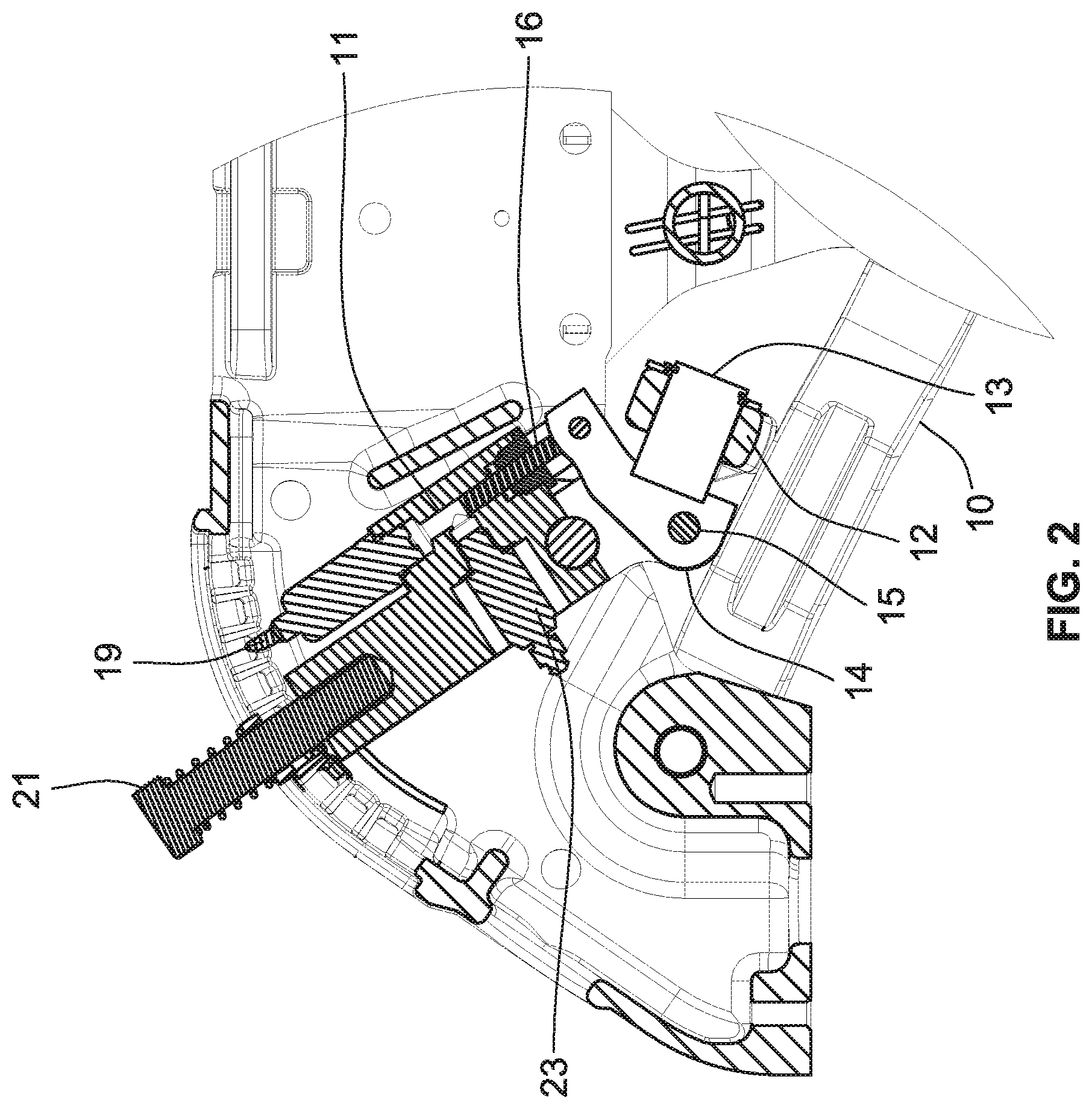
FIG. 2 is an enlargement of the left side of FIG. 1.
FIG. 3 is a bottom perspective of the control portion of the equipment shown in FIG. 1.
FIG. 4 is an enlarged side elevation of the equipment shown in FIG. 3.
FIG. 5 is an enlarged top plan view of the equipment shown in FIG. 3.
FIG. 6 is an enlarged vertical longitudinal section through the equipment shown in FIG. 3.
FIG. 7 is a schematic diagram of a hydraulic control system for controlling the hydraulic system using a gauge wheel load sensor.
FIG. 8 is a schematic diagram of a modified hydraulic control system for controlling the hydraulic system using a gauge wheel load sensor.
FIG. 9 is a waveform diagram illustrating different modes of operation provided by the hydraulic control systems of FIGS. 7 and 8.
FIG. 10 is a plan view of a gauge wheel transducer system for an agricultural planter that includes a gauge wheel and an opener device.
FIG. 11 is a side elevation of the transducer system shown in FIG. 10.
FIG. 12 is a sectional view taken along line A-A in FIG. 10.
FIG. 13 is a side elevation, partially in section, of the transducer system of FIGS. 10-12 mounted on a gauge wheel and its supporting structure.
FIG. 14 is a perspective view of portions of the devices shown in FIG. 13.
FIG. 15 is a plan view similar to FIG. 10 but with portions removed to show the equalizer arm.
FIG. 16 is a plan view of a modified transducer system.
FIG. 17 is a longitudinal section taken along line 17-17 in FIG. 16.
FIG. 18A is a side elevation of a modified sensing system for detecting the pressure exerted on a pair of gauge wheels.
FIG. 18B is an end elevation of the system shown in FIG. 18A.
FIG. 19 is a schematic diagram of a hydraulic and electrical control system for controlling a down pressure actuator.
FIG. 20 is a schematic diagram of a first modified hydraulic and electrical control system for controlling a down pressure actuator.
FIG. 21 is a schematic diagram of a second modified hydraulic and electrical control system for controlling a down pressure actuator.
FIG. 22 is a schematic diagram of a third modified hydraulic and electrical control system for controlling a down pressure actuator.
FIG. 23 is a schematic diagram of a fourth modified hydraulic and electrical control system for controlling a down pressure actuator.
FIG. 24 is a flow chart of an exemplary algorithm executed by the controller in the system of FIG. 23.
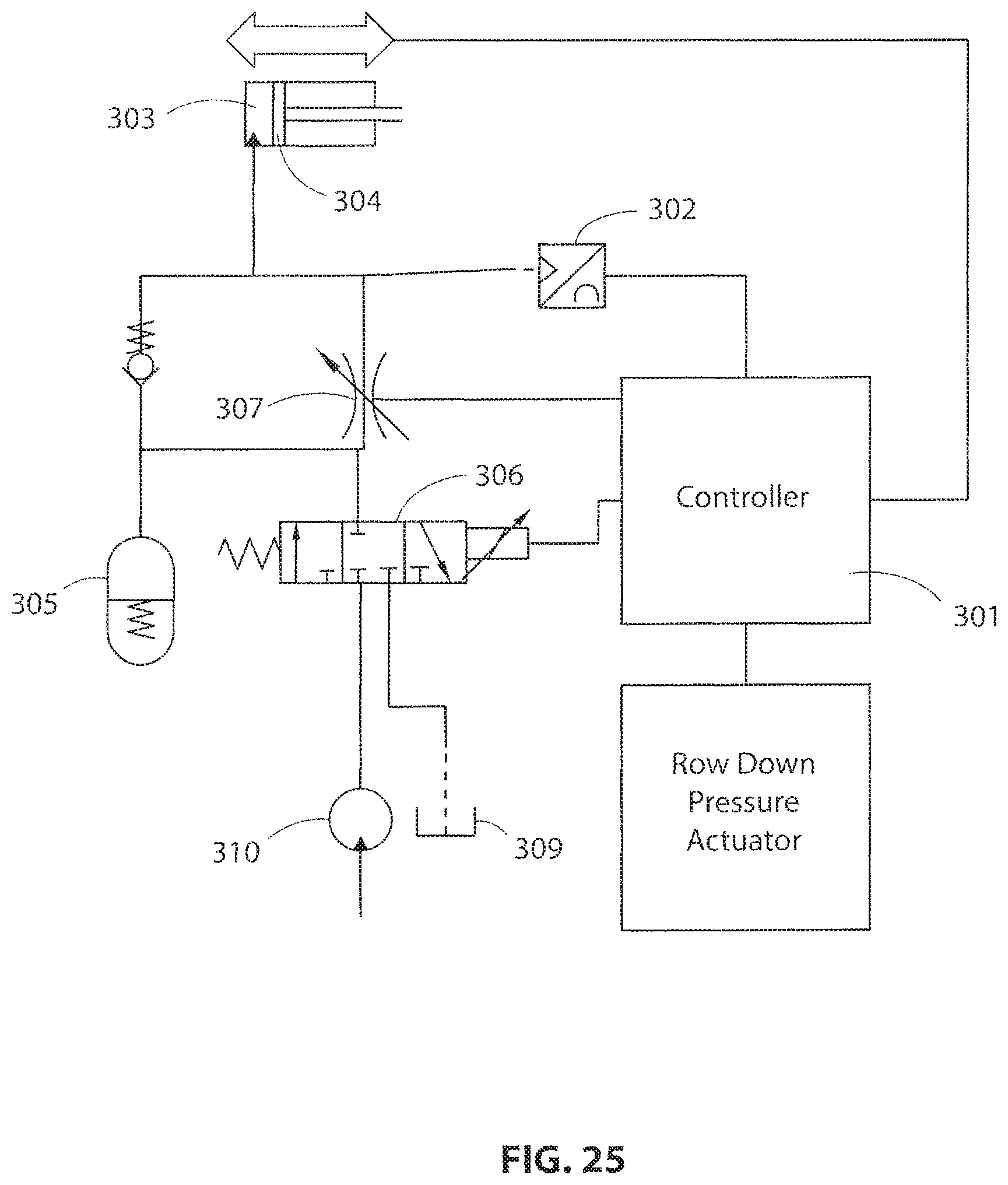
FIG. 25 is a schematic diagram of a fifth modified hydraulic and electrical control system for controlling a down pressure actuator.
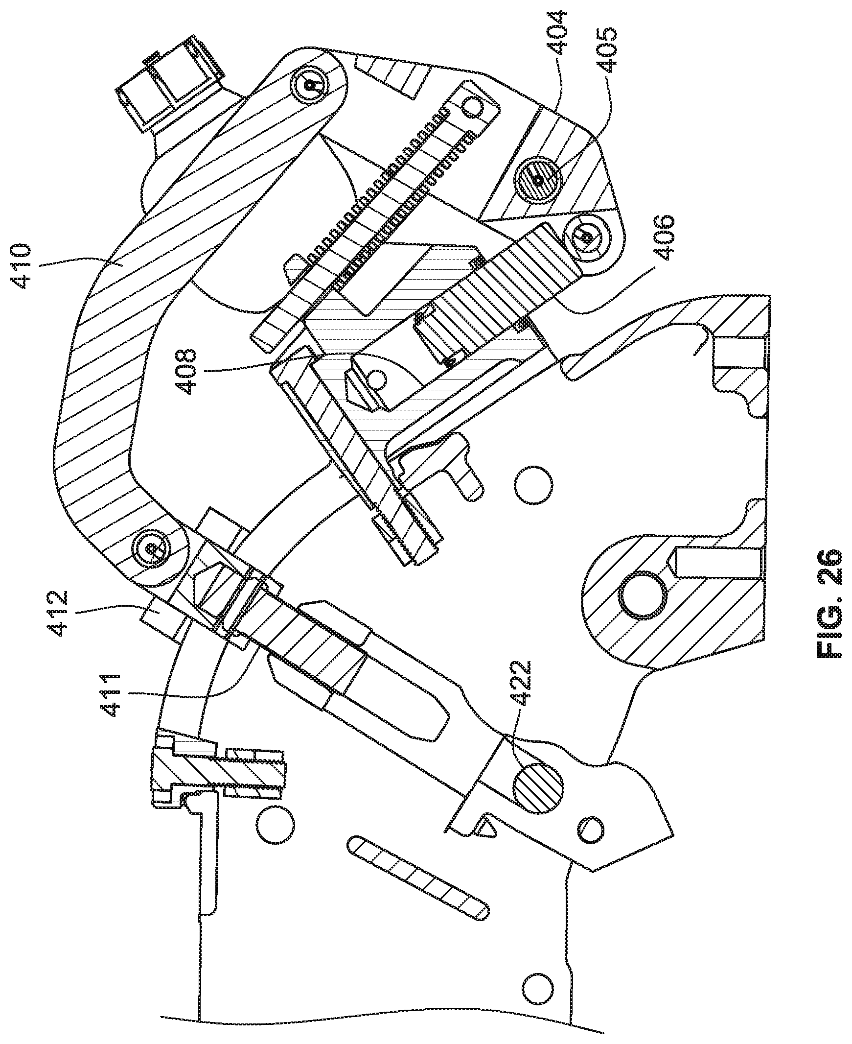
FIG. 26 is sectional elevation of a modified embodiment of an automatic depth control system.
FIG. 27 is a reduced version of the control system of FIG. 26 positioned adjacent a gauge wheel and its support arm.
FIG. 28 is a perspective view of the gauge wheel and control system shown in FIG. 27
FIG. 29 is an enlarged top plan view of the gauge wheel and control system shown in FIG. 28.
FIG. 30 is a side elevation of the control system shown in FIG. 26.
FIG. 31 is an enlarged section taken along line 31-31 in FIG. 30.
FIG. 32 is an enlarged section taken along line 32-32 in FIG. 30.
FIG. 33 is an enlarged view of the slider/depth adjuster in the control system of FIG. 30, with the slider/depth adjuster in two different positions.
FIG. 34 is a flow chart of an algorithm for use in the control system of FIGS. 26-33.
DETAILED DESCRIPTION
An agricultural planter typically includes a number of individual row units, each of which includes its own row cleaner device, row opener device and row closing device. The down pressure is typically controlled separately for each row unit or each of several groups of row units, and is preferably controlled separately for one or more of the individual devices in each row unit, as described in more detail in pending U.S. application Ser. No. 14/146,822 filed Jan. 3, 2014, which is incorporated by reference herein in its entirety.
FIGS. 1-6 illustrate an improved gauge wheel load sensor that takes the upward force from a pivoting planter gauge wheel support, such as the pivoting support arms 10 in the row unit equipment shown in FIGS. 1 and 2, and translates that force into a fluid pressure in a fluid chamber 11. The gauge wheel support arms push against an equalizer support 12, which is connected via a pivot 13 with a rocker/cam 14. The force on the gauge wheel due to the weight of the row unit and applied down force causes the rocker/cam 14 to pivot around a pivot bolt 15 and push against a hydraulic ram 16. This force on the ram 16 causes the fluid in the chamber 11 to pressurize. The pressure is proportional to the amount of gauge wheel load. A pressure transducer 18 reads the amount of pressure and sends a signal to a row unit down pressure controller via signal line 19. This signal allows the planter row unit down pressure to be controlled to a desired level.
Depth adjustment is accomplished in the conventional sense by pivoting the assembly around a pivot 20, and locking a handle 21 into the desired position with a mechanism 22. With this design it is preferred that that there is no air trapped in the fluid chamber 11. For this reason the mechanism includes a bleed valve 23. The process for removal of air is to extend the ram to the maximum extent with calibration/travel limiter plates 24 (FIG. 4) removed. The system is then filled completely with fluid with the bleed valve 23 closed. Then the bleed valve 23 is opened, and the rocker arm 14 is pushed against the ram 16 to move the ram to the exact place where the calibration/travel limit plates 24 allow a calibration plate retaining screw 25 to fit into a hole. This ensures that each assembly is set the same so all the row units of the planter are at the same depth. At this point the bleed valve 23 is closed. With all air removed, the mechanical/fluid system will act as a rigid member against forces in compression. The travel limiter plate 24 keeps a cam pivot weldment from falling down when the planter is lifted off the ground.
Standard industry practice is to use a strain gauge to directly measure the planter gauge wheel load. The design shown in FIGS. 1-6 is an improvement over the state of the art because it allows the sensor to measure only the down force on the gauge wheels. In typical designs using strain gauge type sensors, the mechanical linkage that allows the gauge wheels to oscillate causes the measured wheel force to have substantial noise due to changes in the force being applied. For this reason it can be difficult to determine which parts of the signal correspond to actual changes in down force on the gauge wheels, versus signal changes that are due to movement of components of the gauge wheel support mechanism. The reason for this is that strain gauge sensors will only measure the force that is being applied in a single plane. Because of the linkage and pivot assembly that is used on typical planters, the force being applied to the strain gauge type designs can change based on the depth setting or whether the planter gauge wheels are oscillating over terrain. In this way they will tend to falsely register changes in gauge wheel down force and make it difficult to have a closed loop down pressure response remain consistent.
The fluid seal of the pressure sensor described here creates friction in the system which has the effect of damping out high frequency noise. Agricultural fields have very small scale variations in the surface which cause noise to be produced in the typical down force sensor apparatus. By using fluid pressure this invention decouples the sensor from the mechanical linkage and allows the true gauge wheel force to be more accurately measured. Lowering the amount of systematic noise in the gauge wheel load output sensor makes it easier to produce an automatic control system that accurately responds to true changes in the hardness of the soil, as opposed to perceived changes in soil hardness due to noise induced on the sensor.
FIG. 7 is a schematic diagram of a hydraulic control system for any or all of the hydraulic actuators in a down pressure control system. The hydraulic cylinder 2600 is supplied with pressurized hydraulic fluid from a source 2601 via a first controllable two-position control valve 2602, a restriction 2603 and a check valve 2604. The pressurized hydraulic fluid supplied to the cylinder 2600 can be returned from the cylinder to a sump 2605 via a second controllable two-position control valve 2606, a restriction 2607 and a check valve 2608. Both the control valves 2602 and 2606 are normally closed, but can be opened by energizing respective actuators 2609 and 2610, such as solenoids. Electrical signals for energizing the actuators 2609 and 2610 are supplied to the respective actuators via lines 2611 and 2612 from a controller 2613, which in turn may be controlled by a central processor 2614. The controller 2613 receives input signals from a plurality of sensors, which in the example of FIG. 7 includes a pressure transducer 2615 coupled to the hydraulic cylinder 2600 via line 2616, and a ground hardness sensor 2617. An accumulator 2618 is also coupled to the hydraulic cylinder 2600, and a relief valve 2619 connects the hydraulic cylinder 2600 to the sump 2605 in response to an increase in the pressure in the cylinder 2600 above a predetermined level.
To reduce the energy required from the limited energy source(s) available from the tractor or other propulsion device used to transport the row units over an agricultural field, the control valves 2602 and 2606 are preferably controlled with a pulse width modulation (PWM) control system implemented in the controller 2613. The PWM control system supplies short-duration (e.g., in the range of 50 milliseconds to 2 seconds with orifice sizes in the range of 0.020 to 0.2 inch) pulses to the actuators 2609 and 2610 of the respective control valves 2602 and 2606 to open the respective valves for short intervals corresponding to the widths of the PWM pulses. This significantly reduces the energy required to increase or decrease the pressure in the hydraulic cylinder 2600. The pressure on the exit side of the control valve is determined by the widths of the individual pulses and the number of pulses supplied to the control valves 2602 and 2606. Thus, the pressure applied to the hydraulic cylinder 2622 may be controlled by separately adjusting the two control valves 2602 and 2606 by changing the width and/or the frequency of the electrical pulses supplied to the respective actuators 2609 and 2610, by the controller 2613. This avoids the need for a constant supply current, which is a significant advantage when the only available power source is located on the tractor or other vehicle that propels the soil-engaging implement(s) across a field.
The hydraulic control system of FIG. 7 may be used to control multiple hydraulic cylinders on a single row unit or a group of row units, or may be replicated for each individual hydraulic cylinder on a row unit having multiple hydraulic cylinders. For example, in the system described above having a ground hardness sensor located out in front of the clearing wheels, it is desirable to have each hydraulic cylinder on any given row unit separately controlled so that the down pressure on each tool can be adjusted according to the location of that tool in the direction of travel. Thus, when the ground hardness sensor detects a region where the soil is softer because it is wet, the down pressure on each tool is preferably adjusted to accommodate the softer soil only during the time interval when that particular tool is traversing the wet area, and this time interval is different for each tool when the tools are spaced from each other in the direction of travel. In the case of a group of row units having multiple hydraulic cylinders on each row unit, the same hydraulic control system may control a group of valves having common functions on all the row units in a group.
FIG. 8 is a schematic diagram of a modified hydraulic control system that uses a single three-position control valve 2620 in place of the two two-position control valves and the two check valves used in the system of FIG. 7. The centered position of the valve 2620 is the closed position, which is the normal position of this valve. The valve 2620 has two actuators 2620a and 2620b, one of which moves the valve to a first open position that connects a source 2621 of pressurized hydraulic fluid to a hydraulic cylinder 2622 via restriction 2620c, and the other of which moves the valve to a second open position that connects the hydraulic cylinder 2622 to a sump 2623. Electrical signals for energizing the actuators 2620a and 2620b are supplied to the respective actuators via lines 2624 and 2625 from a controller 2626, which in turn may be controlled by a central processor 2627. The controller 2626 receives input signals from a pressure transducer 2628 coupled to the hydraulic cylinder 2622 via line 2629, and from an auxiliary sensor 2630, such as a ground hardness sensor. An accumulator 2631 is coupled to the hydraulic cylinder 2622, and a relief valve 2632 connects the hydraulic cylinder 2622 to the sump 2623 in response to an increase in the pressure in the cylinder 2622 above a predetermined level.
As depicted in FIG. 9, a PWM control system supplies short-duration pulses P to the actuators 2620a and 2620b of the control valve 2620 to move the valve to either of its two open positions for short intervals corresponding to the widths of the PWM pulses. This significantly reduces the energy required to increase or decrease the pressure in the hydraulic cylinder 2622. In FIG. 9, pulses P1-P3, having a voltage level V1, are supplied to the actuator 2620b when it is desired to increase the hydraulic pressure supplied to the hydraulic cylinder 2622. The first pulse P1 has a width T1 which is shorter than the width of pulses P2 and P3, so that the pressure increase is smaller than the increase that would be produced if P1 had the same width as pulses P2 and P3. Pulses P4-P6, which have a voltage level V2, are supplied to the actuator 2620a when it is desired to decrease the hydraulic pressure supplied to the hydraulic cylinder 2622. The first pulse P4 has a width that is shorter than the width T2 of pulses P2 and P3, so that the pressure decrease is smaller than the decrease that would be produced if P4 had the same width as pulses P5 and P6. When no pulses are supplied to either of the two actuators 2620a and 2620b, as in the "no change" interval in FIG. 9, the hydraulic pressure remains substantially constant in the hydraulic cylinder 2622.
FIGS. 10-15 illustrate a modified gauge wheel load sensor that includes an integrated accumulator 122. The purpose of the accumulator 122 is to damp pressure spikes in the sensor when the planter is operating at low gauge wheel loads. When the forces that the gauge wheel support arms 110 are exerting on the hydraulic ram 117 are near zero, it is more common for the surface of the soil or plant residue to create pressure spikes that are large in relation to the desired system sensor pressure. These pressure spikes produce corresponding changes in the vertical position (elevation) of the gauge wheels. As the target gauge wheel down force increases, and consequently the pressure in the fluid chamber 111, which is coupled to a bleed valve 123, and the transducer output voltage from sensor 118, the small spikes of pressure due to variations in the soil surface or plant residue decrease proportionally.
In the present system, rather than have a perfectly rigid fluid coupling between the ram 117 and the pressure transducer 118, as load increases on the ram 117, the fluid first pushes against a piston 125 of the accumulator 122 that is threaded into a side cavity 123 in the same housing that forms the main cavity for the ram 117. The increased pressure compresses an accumulator spring 126 until the piston 125 rests fully against a shoulder on the interior wall of the accumulator housing 127, thus limiting the retracting movement of the accumulator piston 125. At this point, the system becomes perfectly rigid. The amount of motion permitted for the accumulator piston 125 must be very small so that it does not allow the depth of the gauge wheel setting to fluctuate substantially. The piston accumulator (or other energy storage device) allows the amount of high frequency noise in the system to be reduced at low gauge-wheel loads. Ideally an automatic down pressure control system for an agricultural planter should maintain a down pressure that is as low as possible to avoid over compaction of soil around the area of the seed, which can inhibit plant growth. However, the performance of most systems degrades as the gauge wheel load becomes close to zero, because the amount of latent noise produced from variation in the field surface is large in relation to the desired gauge wheel load.
Planter row units typically have a gauge wheel equalizer arm 130 that is a single unitary piece. It has been observed that the friction between the equalizer arm 130 and the gauge wheel support arms 110, as the gauge wheel 115 oscillates up and down, can generate a substantial amount of noise in the sensor. At different adjustment positions, the edges of the equalizer arm 130 contact the support arms 10 at different orientations and can bite into the surface and prevent forces from being smoothly transferred as they increase and decrease. When the equalizer arm 130 is a single unitary piece, there is necessarily a high amount of friction that manifests itself as signal noise in the sensor. This signal noise makes it difficult to control the down pressure system, especially at low levels of gauge wheel load.
To alleviate this situation, the equalizer arm 130 illustrated in FIG. 16 has a pair of contact rollers 131 and 132 are mounted on opposite ends of the equalizer arm. These rollers 131 and 132 become the interface between the equalizer arm and the support arms 110, allowing forces to be smoothly transferred between the support arms 110 and the equalizer arm 130. The roller system allows the gauge wheel support arms 110 to oscillate relative to each other without producing any sliding friction between the support arms 110 and the equalizer arm 130. This significantly reduces the friction that manifests itself as signal noise in the sensor output, which makes it difficult to control the down pressure control system, especially at low levels of gauge wheel load.
FIG. 17 is a longitudinal section through the device of FIG. 16, with the addition of a rocker arm 150 that engages a ram 151 that controls the fluid pressure within a cylinder 152. A fluid chamber 153 adjacent the inner end of the ram 151 opens into a lateral cavity that contains a pressure transducer 154 that produces an electrical output signal representing the magnitude of the fluid pressure in the fluid chamber 153. The opposite end of the cylinder 152 includes an accumulator 155 similar to the accumulator 122 included in the device of FIG. 12 described above. Between the fluid chamber 153 and the accumulator 155, a pair of valves 156 and 157 are provided in parallel passages 158 and 159 extending between the chamber 153 and the accumulator 155. The valve 156 is a relief valve that allows the pressurized fluid to flow from the chamber 153 to the accumulator 155 when the ram 151 advances farther into the chamber 153. The valve 157 is a check valve that allows pressurized fluid to flow from the accumulator 155 to the chamber 153 when the ram 151 moves outwardly to enlarge the chamber 153. The valves 156 and 157 provide overload protection (e.g., when one of the gauge wheels hits a rock) and to ensure that th
References
D00000
D00001
D00002
D00003
D00004
D00005
D00006
D00007
D00008
D00009
D00010
D00011
D00012

D00013

D00014

D00015

D00016

D00017

D00018

D00019

D00020

D00021

D00022

D00023
D00024
D00025

D00026

D00027

D00028

D00029

D00030

D00031

D00032

XML
uspto.report is an independent third-party trademark research tool that is not affiliated, endorsed, or sponsored by the United States Patent and Trademark Office (USPTO) or any other governmental organization. The information provided by uspto.report is based on publicly available data at the time of writing and is intended for informational purposes only.
While we strive to provide accurate and up-to-date information, we do not guarantee the accuracy, completeness, reliability, or suitability of the information displayed on this site. The use of this site is at your own risk. Any reliance you place on such information is therefore strictly at your own risk.
All official trademark data, including owner information, should be verified by visiting the official USPTO website at www.uspto.gov. This site is not intended to replace professional legal advice and should not be used as a substitute for consulting with a legal professional who is knowledgeable about trademark law.