Method and device for transmitting/receiving broadcast signal
Kwon , et al.
U.S. patent number 10,582,029 [Application Number 16/504,113] was granted by the patent office on 2020-03-03 for method and device for transmitting/receiving broadcast signal. This patent grant is currently assigned to LG ELECTRONICS INC.. The grantee listed for this patent is LG ELECTRONICS INC.. Invention is credited to Minsung Kwak, Woosuk Kwon, Jangwon Lee, Kyoungsoo Moon, Sejin Oh.


View All Diagrams
| United States Patent | 10,582,029 |
| Kwon , et al. | March 3, 2020 |
Method and device for transmitting/receiving broadcast signal
Abstract
A digital broadcast receiver for processing a broadcast signal, includes a tuner configured to receive the broadcast signal including Physical Layer Pipes (PLPs), wherein the PLPs carry link layer packets; and a controller coupled to the tuner, wherein the controller is configured to decode a specific PLP, acquire signaling information for header compression, wherein the signaling information for header compression includes a PLP identifier for the signaling information for header compression, profile information for representing a range of multiple protocols used to compress at least one stream, and a maximum value of a context identifier, decode another PLP to receive the at least one compressed stream based on the signaling information for header compression, and decompress the at least one compressed stream.
| Inventors: | Kwon; Woosuk (Seoul, KR), Oh; Sejin (Seoul, KR), Kwak; Minsung (Seoul, KR), Moon; Kyoungsoo (Seoul, KR), Lee; Jangwon (Seoul, KR) | ||||||||||
|---|---|---|---|---|---|---|---|---|---|---|---|
| Applicant: |
|
||||||||||
| Assignee: | LG ELECTRONICS INC. (Seoul,
KR) |
||||||||||
| Family ID: | 54938465 | ||||||||||
| Appl. No.: | 16/504,113 | ||||||||||
| Filed: | July 5, 2019 |
Prior Publication Data
| Document Identifier | Publication Date | |
|---|---|---|
| US 20190327349 A1 | Oct 24, 2019 | |
Related U.S. Patent Documents
| Application Number | Filing Date | Patent Number | Issue Date | ||
|---|---|---|---|---|---|
| 15980887 | May 16, 2018 | 10389855 | |||
| 14915816 | Jun 12, 2018 | 9998572 | |||
| PCT/KR2015/006506 | Jun 25, 2015 | ||||
| 62054358 | Sep 23, 2014 | ||||
| 62017798 | Jun 26, 2014 | ||||
| Current U.S. Class: | 1/1 |
| Current CPC Class: | H04L 69/22 (20130101); H04L 61/2007 (20130101); H04N 21/434 (20130101); H04N 21/435 (20130101); H04N 21/4381 (20130101); H04N 21/64322 (20130101); H04N 21/2362 (20130101); H04L 29/08 (20130101); H04N 21/2381 (20130101); H04L 69/04 (20130101); H04N 21/235 (20130101); H04N 21/4345 (20130101); H04W 4/06 (20130101); H04L 29/06 (20130101); H04L 69/324 (20130101); H04N 21/814 (20130101); H04N 21/4882 (20130101); H04L 61/6068 (20130101) |
| Current International Class: | H04L 29/06 (20060101); H04L 29/12 (20060101); H04N 21/2362 (20110101); H04L 29/08 (20060101); H04N 21/235 (20110101); H04W 4/06 (20090101); H04N 21/434 (20110101); H04N 21/435 (20110101); H04N 21/2381 (20110101) |
| Field of Search: | ;370/474 |
References Cited [Referenced By]
U.S. Patent Documents
| 2007/0206589 | September 2007 | Yiling et al. |
| 2008/0130561 | June 2008 | Shao et al. |
| 2009/0190677 | July 2009 | Jokela et al. |
| 2010/0296450 | November 2010 | Faniuolo et al. |
| 2011/0286535 | November 2011 | Ko et al. |
| 2012/0063455 | March 2012 | Song et al. |
| 2013/0136064 | May 2013 | Jamadagni et al. |
| 2013/0242847 | September 2013 | Oh et al. |
| 2013/0291027 | October 2013 | Hwang et al. |
| 2013/0291046 | October 2013 | Ko et al. |
| 2014/0010154 | January 2014 | Hong et al. |
| 2015/0349927 | December 2015 | Cohn et al. |
| 2015/0373485 | December 2015 | Chung et al. |
| 2016/0212457 | July 2016 | Kwon et al. |
| 2017/0280172 | September 2017 | Hong et al. |
| 2018/0270334 | September 2018 | Kwon |
| 101730995 | Jun 2010 | CN | |||
| 103733612 | Apr 2014 | CN | |||
| 2348691 | Jul 2011 | EP | |||
| 10-2007-0079275 | Aug 2007 | KR | |||
| 10-2013-0117778 | Oct 2013 | KR | |||
Other References
|
Hefeeda et al., "Design and Evaluation of a Testbed for Mobile TV Networks," Technical Report: TR Mar. 2009, Feb. 2009, (Article in ACM Transactions on Multimedia Computing Communications and Applications, Jan. 2012), pp. 1-26 (27 pages total). cited by applicant. |
Primary Examiner: Solinsky; Peter G
Attorney, Agent or Firm: Birch, Stewart, Kolasch & Birch, LLP
Parent Case Text
CROSS-REFERENCE TO RELATED APPLICATIONS
This Application is a Continuation of U.S. patent application Ser. No. 15/980,887 filed on May 16, 2018 (now U.S. Pat. No. 10,389,855 issued on Aug. 20, 2019), which is a Continuation of U.S. patent application Ser. No. 14/915,816 filed on Mar. 1, 2016 (now U.S. Pat. No. 9,998,572 issued on Jun. 12, 2018), which is the National Phase of PCT International Application No. PCT/KR2015/006506 filed on Jun. 25, 2015, which claims the priority benefit under 35 U.S.C. .sctn. 119(e) to U.S. Provisional Application Nos. 62/054,358 filed on Sep. 23, 2014 and 62/017,798 filed on Jun. 26, 2014, all of these applications are hereby expressly incorporated by reference into the present application.
Claims
What is claimed is:
1. A digital broadcast receiver for processing a broadcast signal, the digital broadcast receiver comprising: a tuner configured to receive the broadcast signal including Physical Layer Pipes (PLPs), wherein the PLPs carry link layer packets; and a controller coupled to the tuner, wherein the controller is configured to: decode a specific PLP, acquire signaling information for header compression, wherein the signaling information for header compression includes a PLP identifier for the signaling information for header compression, profile information for representing a range of multiple protocols used to compress at least one stream, and a maximum value of a context identifier, decode another PLP to receive the at least one compressed stream based on the signaling information for header compression, and decompress the at least one compressed stream.
2. The digital broadcast receiver according to claim 1, wherein the link layer packets include one or more Internet Protocol (IP) packets carrying service acquisition information, and wherein the service acquisition information includes information necessary for fast acquisition of a broadcast service.
3. The digital broadcast receiver according to claim 2, wherein the link layer packets further include mapping information between IP addresses of the one or more IP packets and the PLPs.
4. A method for receiving at least one broadcast signal in a digital broadcast receiver, the method comprising: receiving the at least one broadcast signal including Physical Layer Pipes (PLPs) in a tuner, wherein the PLPs carry link layer packets; decoding a specific PLP; acquiring signaling information for header compression, wherein the signaling information for header compression includes a PLP identifier for the signaling information for header compression, profile information for representing a range of multiple protocols used to compress at least one stream, and a maximum value of a context identifier; decoding another PLP to receive the at least one compressed stream based on the signaling information for header compression; and decompressing the at least one compressed stream.
5. The method according to claim 4, wherein the link layer packets include one or more Internet Protocol (IP) packets carrying service acquisition information, and wherein the service acquisition information includes information necessary for fast acquisition of a broadcast service.
6. The method according to claim 5, wherein the link layer packets further include mapping information between IP addresses of the one or more of IP packets and the PLPs.
7. A method for transmitting a broadcast signal in a digital broadcast transmitter, the method comprising: generating a compression information table for a header compression for at least one Internet Protocol (IP) packet; encapsulating the at least one IP packet into at least one link layer packet, wherein the compression information table for the header compression for the at least one IP packet includes a Physical Layer Pipe (PLP) identifier for identifying at least one PLP, wherein the compression information table for the header compression for the at least one IP packet further includes a maximum value of a context identifier to be used for the at least one PLP, and wherein the compression information table for the header compression for the at least one IP packet further includes profile information for representing a range of multiple protocols used to compress an IP stream; and transmitting the broadcast signal including the at least one PLP that carries the at least one link layer packet.
8. The method of claim 7, wherein a number of bits for the PLP identifier is smaller than a number of bits for the maximum value of the context identifier, and a number of bits for the profile information corresponds to eight bits.
9. A digital broadcast transmitter for transmitting a broadcast signal, the digital broadcast transmitter comprising: a processor configured to: generate a compression information table for a header compression for at least one Internet Protocol (IP) packet, and encapsulate the at least one IP packet into at least one link layer packet, wherein the compression information table for the header compression for the at least one IP packet includes a Physical Layer Pipe (PLP) identifier for identifying at least one PLP, wherein the compression information table for the header compression for the at least one IP packet further includes a maximum value of a context identifier to be used for the at least one PLP, and wherein the compression information table for the header compression for the at least one IP packet further includes profile information for representing a range of multiple protocols used to compress an IP stream; and a transmitter configured to transmit the broadcast signal including the at least one PLP that carries the at least one link layer packet.
10. The digital broadcast transmitter of claim 9, wherein a number of bits for the PLP identifier is smaller than a number of bits for the maximum value of the context identifier, and a number of bits for the profile information corresponds to eight bits.
Description
BACKGROUND OF THE INVENTION
Field of the Invention
The present invention relates to a method and apparatus for transmitting/receiving a media signal. More specifically, the present invention relates to a method and apparatus for processing data about media transmitted respectively through a broadband network and a broadcast network in a broadcast system in which the broadband and broadcast networks are combined.
Discussion of the Related Art
Transmission/reception of IP-based broadcast signals has been extended in digital broadcast systems. Specifically, the importance of Internet protocol (IP)-based broadcast signal transmission/reception environments has been emphasized in the mobile digital broadcast schemes, for example, DVB-NGH from among European broadcast standards or ATSC-MH from among North American standards. In addition, it is expected that a hybrid broadcast system designed to be interoperable with a broadcast network or an Internet network will be constructed in the next generation broadcast system.
In the hybrid broadcast system, since a scheme of transmitting data via an existing broadcast network and a scheme of transmitting data via a broadband network coexist, a scheme of processing the data is different from that in an existing broadcast receiver.
In addition, according to expansion of an IP-based broadcast system, an emergency alert message needs to be transmitted through a broadcast network. However, so far, a method for transmitting the emergency alert message has not been obviously defined.
Further, although many broadcast services could be provided due to expansion of the IP-based broadcast system, a method for enabling a viewer to efficiently search for a desired broadcast service has not been supported.
Furthermore, although a scheme of processing data included in broadcast signals can be expanded or changed according to expansion of the broadcast system, how to deal with such expansion or change of the data processing scheme in the broadcast system has not been provided.
SUMMARY OF THE INVENTION
A technical object to be achieved by the present invention is to solve the aforementioned problems and provides a proper method and apparatus for processing data when a data transmission scheme via an existing broadcast network and a data transmission scheme via a broadband network coexist in a hybrid broadcast system.
Another object of the present invention is to provide a method and apparatus for efficiently transmitting an emergency alert message via a broadcast system.
Another object of the present invention is to provide a method and apparatus for enabling a viewer to efficiently search for a desired broadcast service.
Another object of the present invention is to provide a method for performing an initialization procedure for data processing in a link layer.
Another object of the present invention is to provide an efficient signaling method when a transmission session based protocol is applied to a broadcast system.
According to an aspect of the present invention, provided herein is a broadcast transmitter for transmitting a broadcast signal, including an Internet protocol (IP) packet generator for generating first IP packets including broadcast data for a broadcast service and generating a second IP packet including service acquisition information including information necessary for fast acquisition of the broadcast service, a link layer packet generator for generating first link layer packets including the first IP packets, and a broadcast signal generator for generating the broadcast signal including the first link layer packets and the second IP packet.
The service acquisition information may include information identifying an IP address of a channel for transmission of service layer signaling including information specifying the broadcast service.
The service acquisition information may include information identifying a data pipe (DP) including the service layer signaling.
The second IP packet may further include a signaling information part including addition information used to identify a processing method of signaling data included in the second IP packet and the signaling information part may include signaling class information identifying whether the signaling data transmitted through the second IP packet corresponds to the service acquisition information.
The link layer packet generator may further generate a second link layer packet including link layer signaling data.
The second link layer packet may further include a signaling information part including additional information used to identify a processing method of the signaling data included in the second link layer packet and the signaling information part may include signaling class information identifying whether the signaling data transmitted through the second link layer packet corresponds to the service acquisition information.
The link layer signaling data may include at least one of encapsulation mode information identifying an encapsulation scheme used to encapsulate the broadcast data in a link layer, header compression mode information identifying a header compression scheme applied to an IP packet processed in the link layer, packet reconfiguration mode information specifying a structure of the IP packet processed in the link layer, and signaling path configuration information identifying a path transmitting signaling information.
According to another aspect of the present invention, provided herein is a broadcast receiver for receiving a broadcast signal, including a receiver for receiving the broadcast signal including first link layer packets and a second Internet protocol (IP) packet, wherein the second IP packet includes service acquisition information including information necessary for fast acquisition of a broadcast service, a link layer processing unit for acquiring first IP packets including broadcast data for the broadcast service by decapsulating the first link layer packets, a signaling processing unit for acquiring the service acquisition information by decapsulating the second IP packet, an IP packet processing unit for acquiring the broadcast data by decapsulating the first IP packets, using the service acquisition information, and a processor for reproducing and processing broadcast content using the broadcast data.
The service acquisition information may include information identifying an IP address of a channel for transmission of service layer signaling including information specifying the broadcast service.
The service acquisition information may include information identifying a data pipe (DP) including the service layer signaling.
The second IP packet may further include a signaling information part including addition information used to identify a processing method of signaling data included in the second IP packet and the signaling information part may include signaling class information identifying whether the signaling data transmitted through the second IP packet corresponds to the service acquisition information.
The link layer packet generator may further generate a second link layer packet including link layer signaling data.
The second link layer packet may further include a signaling information part including additional information used to identify a processing method of the signaling data included in the second link layer packet and the signaling information part may include signaling class information identifying whether the signaling data transmitted through the second link layer packet corresponds to the service acquisition information.
The link layer signaling data may include at least one of encapsulation mode information identifying an encapsulation scheme used to encapsulate the broadcast data in a link layer, header compression mode information identifying a header compression scheme applied to an IP packet processed in the link layer, packet reconfiguration mode information specifying a structure of the IP packet processed in the link layer, and signaling path configuration information identifying a path transmitting signaling information.
According to the present invention, in a hybrid broadcast system, both data transmitted through an existing broadcast network and data transmitted through a broadband network can be efficiently processed.
According to the present invention, an emergency alert message can be efficiently transmitted through a broadcast system.
According to the present invention, a viewer can efficiently search for a desired broadcast service.
According to the present invention, processing of a link layer that can operate independently of change of a higher layer with respect to an IP layer, an MPEG-2 TS layer, and other protocol layers corresponding to the IP layer and the MPEG-2 TS layer can be performed.
According to the present invention, data can be processed in a link layer that can independently operate without being influenced by a physical layer through which broadcast content is to be transmitted.
According to the present invention, a layer that can be easily expanded later can be configured through organization of functional blocks constituting a link layer.
According to the present invention, signaling transmission can be performed via multiple paths through a link layer, thereby acquiring efficiency of signaling transmission.
According to the present invention, bandwidth of a broadcast system and a processing time of broadcast data can be efficiently used through a control function of a link layer.
BRIEF DESCRIPTION OF THE DRAWINGS
The accompanying drawings, which are included to provide a further understanding of the invention and are incorporated in and constitute a part of this application, illustrate embodiment(s) of the invention and together with the description serve to explain the principle of the invention. In the drawings:
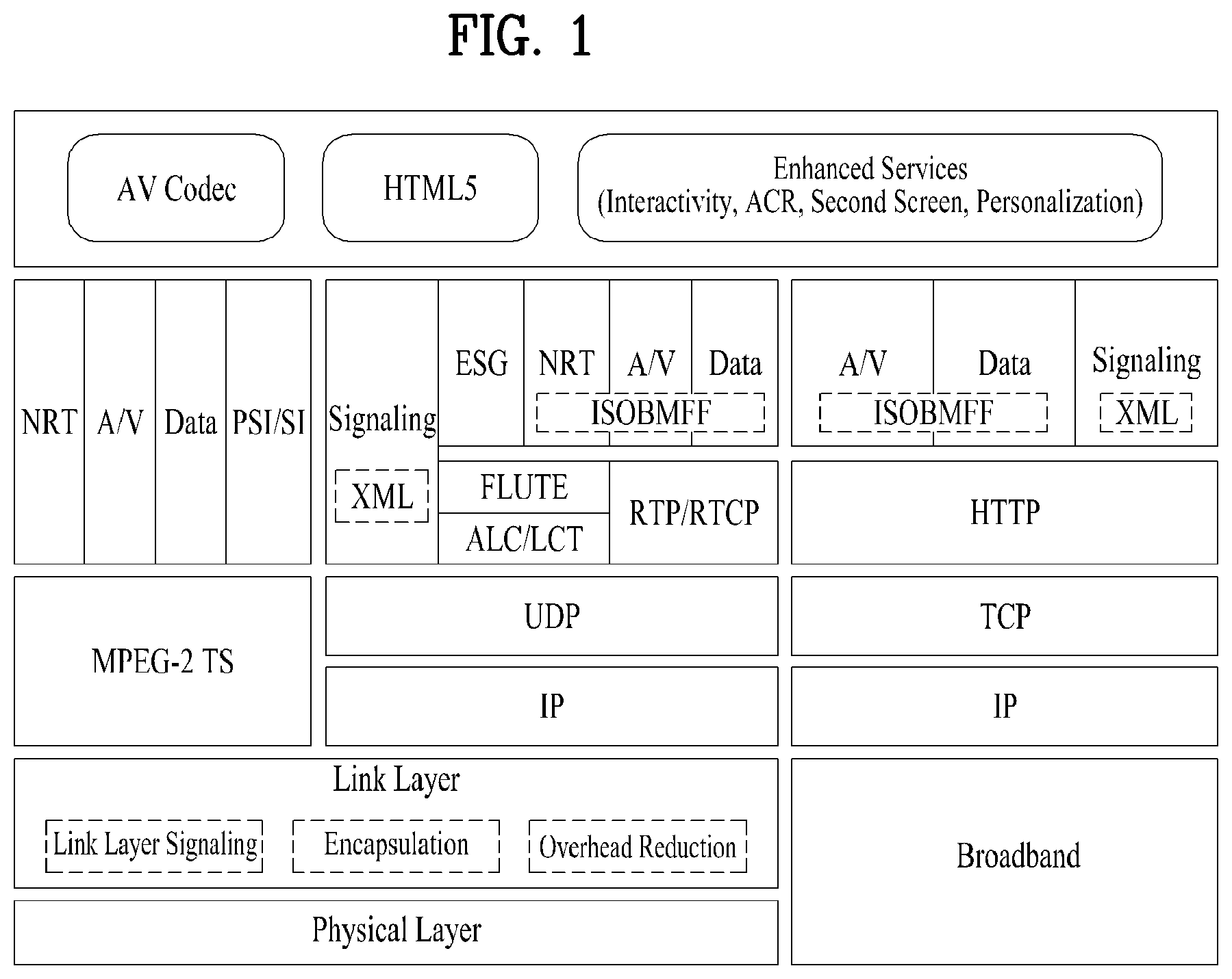
FIG. 1 is a view showing a protocol stack for a next generation broadcasting system according to an embodiment of the present invention.
FIG. 2 is a conceptual diagram illustrating an interface of a link layer according to an embodiment of the present invention.
FIG. 3 illustrates an operation in a normal mode corresponding to one of operation modes of a link layer according to an embodiment of the present invention.
FIG. 4 illustrates an operation in a transparent mode corresponding to one of operation modes of a link layer according to an embodiment of the present invention.
FIG. 5 illustrates a configuration of a link layer at a transmitter according to an embodiment of the present invention (normal mode).
FIG. 6 illustrates a configuration of a link layer at a receiver according to an embodiment of the present invention (normal mode).
FIG. 7 is a diagram illustrating definition according to link layer organization type according to an embodiment of the present invention.
FIG. 8 is a diagram illustrating processing of a broadcast signal when a logical data path includes only a normal data pipe according to an embodiment of the present invention.
FIG. 9 is a diagram illustrating processing of a broadcast signal when a logical data path includes a normal data pipe and a base data pipe according to an embodiment of the present invention.
FIG. 10 is a diagram illustrating processing of a broadcast signal when a logical data path includes a normal data pipe and a dedicated channel according to an embodiment of the present invention.
FIG. 11 is a diagram illustrating processing of a broadcast signal when a logical data path includes a normal data pipe, a base data pipe, and a dedicated channel according to an embodiment of the present invention.
FIG. 12 is a diagram illustrating a detailed processing operation of a signal and/or data in a link layer of a receiver when a logical data path includes a normal data pipe, a base data pipe, and a dedicated channel according to an embodiment of the present invention.
FIG. 13 is a diagram illustrating syntax of a fast information channel (FIC) according to an embodiment of the present.
FIG. 14 is a diagram illustrating syntax of an emergency alert table (EAT) according to an embodiment of the present invention.
FIG. 15 is a diagram illustrating a packet transmitted to a data pipe according to an embodiment of the present invention.
FIG. 16 is a diagram illustrating a detailed processing operation of a signal and/or data in each protocol stack of a transmitter when a logical data path of a physical layer includes a dedicated channel, a base DP, and a normal data DP, according to another embodiment of the present invention.
FIG. 17 is a diagram illustrating a detailed processing operation of a signal and/or data on each protocol stack of a receiver when a logical data path of a physical layer includes a dedicated channel, a base DP, and a normal data DP, according to another embodiment of the present invention.
FIG. 18 is a diagram illustrating a syntax of an FIC according to another embodiment of the present invention.
FIG. 19 is a diagram illustrating signaling_Information_Part( ) according to an embodiment of the present invention.
FIG. 20 is a diagram illustrating a procedure for controlling an operation mode of a transmitter and/or a receiver in a link layer according to an embodiment of the present invention.
FIG. 21 is a diagram illustrating an operation in a link layer according to a value of a flag and a type of a packet transmitted to a physical layer according to an embodiment of the present invention.
FIG. 22 is a diagram illustrating a descriptor for signaling a mode control parameter according to an embodiment of the present invention.
FIG. 23 is a diagram illustrating an operation of a transmitter for controlling an operation mode according to an embodiment of the present invention.
FIG. 24 is a diagram illustrating an operation of a receiver for processing a broadcast signal according to an operation mode according to an embodiment of the present invention.
FIG. 25 is a diagram illustrating information for identifying an encapsulation mode according to an embodiment of the present invention.
FIG. 26 is a diagram illustrating information for identifying a header compression mode according to an embodiment of the present invention.
FIG. 27 is a diagram illustrating information for identifying a packet reconfiguration mode according to an embodiment of the present invention.
FIG. 28 is a diagram illustrating a context transmission mode according to an embodiment of the present invention.
FIG. 29 is a diagram illustrating initialization information when RoHC is applied by a header compression scheme according to an embodiment of the present invention.
FIG. 30 is a diagram illustrating information for identifying link layer signaling path configuration according to an embodiment of the present invention.
FIG. 31 is a diagram illustrating information about signaling path configuration by a bit mapping scheme according to an embodiment of the present invention.
FIG. 32 is a flowchart illustrating a link layer initialization procedure according to an embodiment of the present invention.
FIG. 33 is a flowchart illustrating a link layer initialization procedure according to another embodiment of the present invention.
FIG. 34 is a diagram illustrating a signaling format for transmitting an initialization parameter according to an embodiment of the present invention.
FIG. 35 is a diagram illustrating a signaling format for transmitting an initialization parameter according to another embodiment of the present invention.
FIG. 36 is a diagram illustrating a signaling format for transmitting an initialization parameter according to another embodiment of the present invention.
FIG. 37 is a diagram illustrating a receiver according to an embodiment of the present invention.
FIG. 38 is a diagram illustrating a broadcast system according to an embodiment of the present invention.
DETAILED DESCRIPTION OF THE EMBODIMENTS
Reference will now be made in detail to the preferred embodiments of the present invention, examples of which are illustrated in the accompanying drawings. The detailed description, which will be given below with reference to the accompanying drawings, is intended to explain exemplary embodiments of the present invention, rather than to show the only embodiments that can be implemented according to the present invention.
Although most terms of elements in this specification have been selected from general ones widely used in the art taking into consideration functions thereof in this specification, the terms may be changed depending on the intention or convention of those skilled in the art or the introduction of new technology. Some terms have been arbitrarily selected by the applicant and their meanings are explained in the following description as needed. Thus, the terms used in this specification should be construed based on the overall content of this specification together with the actual meanings of the terms rather than their simple names or meanings.
The term "signaling" in the present invention may indicate that service information (SI) that is transmitted and received from a broadcast system, an Internet system, and/or a broadcast/Internet convergence system. The service information (SI) may include broadcast service information (e.g., ATSC-SI and/or DVB-SI) received from the existing broadcast systems.
The term "broadcast signal" may conceptually include not only signals and/or data received from a terrestrial broadcast, a cable broadcast, a satellite broadcast, and/or a mobile broadcast, but also signals and/or data received from bidirectional broadcast systems such as an Internet broadcast, a broadband broadcast, a communication broadcast, a data broadcast, and/or VOD (Video On Demand).
The term "PLP" may indicate a predetermined unit for transmitting data contained in a physical layer. Therefore, the term "PLP" may also be replaced with the terms `data unit` or `data pipe` as necessary.
A hybrid broadcast service configured to interwork with the broadcast network and/or the Internet network may be used as a representative application to be used in a digital television (DTV) service. The hybrid broadcast service transmits, in real time, enhancement data related to broadcast A/V (Audio/Video) contents transmitted through the terrestrial broadcast network over the Internet, or transmits, in real time, some parts of the broadcast A/V contents over the Internet, such that users can experience a variety of contents.
FIG. 1 is a view showing a protocol stack for a next generation broadcasting system according to an embodiment of the present invention.
The broadcasting system according to the present invention may correspond to a hybrid broadcasting system in which an Internet Protocol (IP) centric broadcast network and a broadband are coupled.
The broadcasting system according to the present invention may be designed to maintain compatibility with a conventional MPEG-2 based broadcasting system.
The broadcasting system according to the present invention may correspond to a hybrid broadcasting system based on coupling of an IP centric broadcast network, a broadband network, and/or a mobile communication network (or a cellular network).
Referring to the figure, a physical layer may use a physical protocol adopted in a broadcasting system, such as an ATSC system and/or a DVB system. For example, in the physical layer according to the present invention, a transmitter/receiver may transmit/receive a terrestrial broadcast signal and convert a transport frame including broadcast data into an appropriate form.
In an encapsulation layer, an IP datagram is acquired from information acquired from the physical layer or the acquired IP datagram is converted into a specific frame (for example, an RS Frame, GSE-lite, GSE, or a signal frame). The frame main include a set of IP datagrams. For example, in the encapsulation layer, the transmitter include data processed from the physical layer in a transport frame or the receiver extracts an MPEG-2 TS and an IP datagram from the transport frame acquired from the physical layer.
A fast information channel (FIC) includes information (for example, mapping information between a service ID and a frame) necessary to access a service and/or content. The FIC may be named a fast access channel (FAC).
The broadcasting system according to the present invention may use protocols, such as an Internet Protocol (IP), a User Datagram Protocol (UDP), a Transmission Control Protocol (TCP), an Asynchronous Layered Coding/Layered Coding Transport (ALC/LCT), a Rate Control Protocol/RTP Control Protocol (RCP/RTCP), a Hypertext Transfer Protocol (HTTP), and a File Delivery over Unidirectional Transport (FLUTE). A stack between these protocols may refer to the structure shown in the figure.
In the broadcasting system according to the present invention, data may be transported in the form of an ISO based media file format (ISOBMFF). An Electrical Service Guide (ESG), Non Real Time (NRT), Audio/Video (A/V), and/or general data may be transported in the form of the ISOBMFF.
Transport of data through a broadcast network may include transport of a linear content and/or transport of a non-linear content.
Transport of RTP/RTCP based A/V and data (closed caption, emergency alert message, etc.) may correspond to transport of a linear content.
An RTP payload may be transported in the form of an RTP/AV stream including a Network Abstraction Layer (NAL) and/or in a form encapsulated in an ISO based media file format. Transport of the RTP payload may correspond to transport of a linear content. Transport in the form encapsulated in the ISO based media file format may include an MPEG DASH media segment for A/V, etc.
Transport of a FLUTE based ESG, transport of non-timed data, transport of an NRT content may correspond to transport of a non-linear content. These may be transported in an MIME type file form and/or a form encapsulated in an ISO based media file format. Transport in the form encapsulated in the ISO based media file format may include an MPEG DASH media segment for A/V, etc.
Transport through a broadband network may be divided into transport of a content and transport of signaling data.
Transport of the content includes transport of a linear content (A/V and data (closed caption, emergency alert message, etc.)), transport of a non-linear content (ESG, non-timed data, etc.), and transport of a MPEG DASH based Media segment (A/V and data).
Transport of the signaling data may be transport including a signaling table (including an MPD of MPEG DASH) transported through a broadcasting network.
In the broadcasting system according to the present invention, synchronization between linear/non-linear contents transported through the broadcasting network or synchronization between a content transported through the broadcasting network and a content transported through the broadband may be supported. For example, in a case in which one UD content is separately and simultaneously transported through the broadcasting network and the broadband, the receiver may adjust the timeline dependent upon a transport protocol and synchronize the content through the broadcasting network and the content through the broadband to reconfigure the contents as one UD content.
An applications layer of the broadcasting system according to the present invention may realize technical characteristics, such as Interactivity, Personalization, Second Screen, and automatic content recognition (ACR). These characteristics are important in extension from ATSC 2.0 to ATSC 3.0. For example, HTML5 may be used for a characteristic of interactivity.
In a presentation layer of the broadcasting system according to the present invention, HTML and/or HTML5 may be used to identify spatial and temporal relationships between components or interactive applications.
In the present invention, signaling includes signaling information necessary to support effective acquisition of a content and/or a service. Signaling data may be expressed in a binary or XMK form. The signaling data may be transmitted through the terrestrial broadcasting network or the broadband.
A real-time broadcast A/V content and/or data may be expressed in an ISO Base Media File Format, etc. In this case, the A/V content and/or data may be transmitted through the terrestrial broadcasting network in real time and may be transmitted based on IP/UDP/FLUTE in non-real time. Alternatively, the broadcast A/V content and/or data may be received by receiving or requesting a content in a streaming mode using Dynamic Adaptive Streaming over HTTP (DASH) through the Internet in real time. In the broadcasting system according to the embodiment of the present invention, the received broadcast A/V content and/or data may be combined to provide various enhanced services, such as an Interactive service and a second screen service, to a viewer.
In a hybrid-based broadcast system of a TS and an IP stream, a link layer may be used to transmit data having a TS or IP stream type. When various types of data are to be transmitted through a physical layer, the link layer may convert the data into a format supported by the physical layer and deliver the converted data to the physical layer. In this way, the various types of data may be transmitted through the same physical layer. Here, the physical layer may correspond to a step of transmitting data using an MIMO/MISO scheme or the like by interleaving, multiplexing, and/or modulating the data.
The link layer needs to be designed such that an influence on an operation of the link layer is minimized even when a configuration of the physical layer is changed. In other words, the operation of the link layer needs to be configured such that the operation may be compatible with various physical layers.
The present invention proposes a link layer capable of independently operating irrespective of types of an upper layer and a lower layer. In this way, it is possible to support various upper layers and lower layers. Here, the upper layer may refer to a layer of a data stream such as a TS stream, an IP stream, or the like. Here, the lower layer may refer to the physical layer. In addition, the present invention proposes a link layer having a correctable structure in which a function supportable by the link layer may be extended/added/deleted. Moreover, the present invention proposes a scheme of including an overhead reduction function in the link layer such that radio resources may be efficiently used.
In this figure, protocols and layers such as IP, UDP, TCP, ALC/LCT, RCP/RTCP, HTTP, FLUTE, and the like are as described above.
In this figure, a link layer t88010 may be another example of the above-described data link (encapsulation) part. The present invention proposes a configuration and/or an operation of the link layer t88010. The link layer t88010 proposed by the present invention may process signaling necessary for operations of the link layer and/or the physical layer. In addition, the link layer t88010 proposed by the present invention may encapsulate TS and IP packets and the like, and perform overhead reduction in this process.
The link layer t88010 proposed by the present invention may be referred to by several terms such as data link layer, encapsulation layer, layer 2, and the like. According to a given embodiment, a new term may be applied to the link layer and used.
FIG. 2 is a conceptual diagram illustrating an interface of a link layer according to an embodiment of the present invention.
Referring to FIG. 2, the transmitter may consider an exemplary case in which IP packets and/or MPEG-2 TS packets mainly used in the digital broadcasting are used as input signals. The transmitter may also support a packet structure of a new protocol capable of being used in the next generation broadcast system. The encapsulated data of the link layer and signaling information may be transmitted to a physical layer. The transmitter may process the transmitted data (including signaling data) according to the protocol of a physical layer supported by the broadcast system, such that the transmitter may transmit a signal including the corresponding data.
On the other hand, the receiver may recover data and signaling information received from the physical layer into other data capable of being processed in a higher layer. The receiver may read a header of the packet, and may determine whether a packet received from the physical layer indicates signaling information (or signaling data) or recognition data (or content data).
The signaling information (i.e., signaling data) received from the link layer of the transmitter may include first signaling information that is received from an upper layer and needs to be transmitted to an upper layer of the receiver; second signaling information that is generated from the link layer and provides information regarding data processing in the link layer of the receiver; and/or third signaling information that is generated from the upper layer or the link layer and is transferred to quickly detect specific data (e.g., service, content, and/or signaling data) in a physical layer.
FIG. 3 illustrates an operation in a normal mode corresponding to one of operation modes of a link layer according to an embodiment of the present invention.
The link layer proposed by the present invention may have various operation modes for compatibility between an upper layer and a lower layer. The present invention proposes a normal mode and a transparent mode of the link layer. Both the operation modes may coexist in the link layer, and an operation mode to be used may be designated using signaling or a system parameter. According to a given embodiment, one of the two operation modes may be implemented. Different modes may be applied according to an IP layer, a TS layer, and the like input to the link layer. In addition, different modes may be applied for each stream of the IP layer and for each stream of the TS layer.
According to a given embodiment, a new operation mode may be added to the link layer. The new operation mode may be added based on configurations of the upper layer and the lower layer. The new operation mode may include different interfaces based on the configurations of the upper layer and the lower layer. Whether to use the new operation mode may be designated using signaling or a system parameter.
In the normal mode, data may be processed through all functions supported by the link layer, and then delivered to a physical layer.
First, each packet may be delivered to the link layer from an IP layer, an MPEG-2 TS layer, or another particular layer t89010. In other words, an IP packet may be delivered to the link layer from an IP layer. Similarly, an MPEG-2 TS packet may be delivered to the link layer from the MPEG-2 TS layer, and a particular packet may be delivered to the link layer from a particular protocol layer.
Each of the delivered packets may go through or not go through an overhead reduction process t89020, and then go through an encapsulation process t89030.
First, the IP packet may go through or not go through the overhead reduction process t89020, and then go through the encapsulation process t89030. Whether the overhead reduction process t89020 is performed may be designated by signaling or a system parameter. According to a given embodiment, the overhead reduction process t89020 may be performed or not performed for each IP stream. An encapsulated IP packet may be delivered to the physical layer.
Second, the MPEG-2 TS packet may go through the overhead reduction process t89020, and go through the encapsulation process t89030. The MPEG-2 TS packet may not be subjected to the overhead reduction process t89020 according to a given embodiment. However, in general, a TS packet has sync bytes (0.times.47) and the like at the front and thus it may be efficient to eliminate such fixed overhead. The encapsulated TS packet may be delivered to the physical layer.
Third, a packet other than the IP or TS packet may or may not go through the overhead reduction process t89020, and then go through the encapsulation process t89030. Whether or not the overhead reduction process t89020 is performed may be determined according to characteristics of the corresponding packet. Whether the overhead reduction process t89020 is performed may be designated by signaling or a system parameter. The encapsulated packet may be delivered to the physical layer.
In the overhead reduction process t89020, a size of an input packet may be reduced through an appropriate scheme. In the overhead reduction process t89020, particular information may be extracted from the input packet or generated. The particular information is information related to signaling, and may be transmitted through a signaling region. The signaling information enables a receiver to restore an original packet by restoring changes due to the overhead reduction process t89020. The signaling information may be delivered to a link layer signaling process t89050.
The link layer signaling process t89050 may transmit and manage the signaling information extracted/generated in the overhead reduction process t89020. The physical layer may have physically/logically divided transmission paths for signaling, and the link layer signaling process t89050 may deliver the signaling information to the physical layer according to the divided transmission paths. Here, the above-described FIC signaling process t89060, EAS signaling process t89070, or the like may be included in the divided transmission paths. Signaling information not transmitted through the divided transmission paths may be delivered to the physical layer through the encapsulation process t89030.
Signaling information managed by the link layer signaling process t89050 may include signaling information delivered from the upper layer, signaling information generated in the link layer, a system parameter, and the like. Specifically, the signaling information may include signaling information delivered from the upper layer to be subsequently delivered to an upper layer of the receiver, signaling information generated in the link layer to be used for an operation of a link layer of the receiver, signaling information generated in the upper layer or the link layer to be used for rapid detection in a physical layer of the receiver, and the like.
Data going through the encapsulation process t89030 and delivered to the physical layer may be transmitted through a data pipe (DP) t89040. Here, the DP may be a physical layer pipe (PLP). Signaling information delivered through the above-described divided transmission paths may be delivered through respective transmission paths. For example, an FIC signal may be transmitted through an FIC t89080 designated in a physical frame. In addition, an EAS signal may be transmitted through an EAC t89090 designated in a physical frame. Information about presence of a dedicated channel such as the FIC, the EAC, or the like may be transmitted to a preamble area of the physical layer through signaling, or signaled by scrambling a preamble using a particular scrambling sequence. According to a given embodiment, FIC signaling/EAS signaling information may be transmitted through a general DP area, PLS area, or preamble rather than a designated dedicated channel.
The receiver may receive data and signaling information through the physical layer. The receiver may restore the received data and signaling information into a form processable in the upper layer, and deliver the restored data and signaling information to the upper layer. This process may be performed in the link layer of the receiver. The receiver may verify whether a received packet is related to the signaling information or the data by reading a header of the packet and the like. In addition, when overhead reduction is performed at a transmitter, the receiver may restore a packet, overhead of which has been reduced through the overhead reduction process, to an original packet. In this process, the received signaling information may be used.
FIG. 4 illustrates an operation in a transparent mode corresponding to one of operation modes of a link layer according to an embodiment of the present invention.
In the transparent mode, data may not be subjected to functions supported by the link layer or may be subjected to some of the functions, and then delivered to a physical layer. In other words, in the transparent mode, a packet delivered to an upper layer may be delivered to a physical layer without going through a separate overhead reduction and/or encapsulation process. Other packets may go through the overhead reduction and/or encapsulation process as necessary. The transparent mode may be referred to as a bypass mode, and another term may be applied to the transparent mode.
According to a given embodiment, some packets may be processed in the normal mode and some packets may be processed in the transparent mode based on characteristics of the packets and a system operation.
A packet to which the transparent mode may be applied may be a packet having a type well known to a system. When the packet may be processed in the physical layer, the transparent mode may be used. For example, a well-known TS or IP packet may go through separate overhead reduction and input formatting processes in the physical layer and thus the transparent mode may be used in a link layer step. When the transparent mode is applied and a packet is processed through input formatting and the like in the physical layer, an operation such as the above-described TS header compression may be performed in the physical layer. On the other hand, when the normal mode is applied, a processed link layer packet may be treated as a GS packet and processed in the physical layer.
In the transparent mode, a link layer signaling module may be included when signal transmission needs to be supported. As described above, the link layer signaling module may transmit and manage signaling information. The signaling information may be encapsulated and transmitted through a DP, and FIC signaling information and EAS signaling information having divided transmission paths may be transmitted through an FIC and an EAC, respectively.
In the transparent mode, whether information corresponds to signaling information may be displayed using a fixed IP address and port number. In this case, the signaling information may be filtered to configure a link layer packet, and then transmitted through the physical layer.
FIG. 5 illustrates a configuration of a link layer at a transmitter according to an embodiment of the present invention (normal mode).
The present embodiment is an embodiment presuming that an IP packet is processed. The link layer at the transmitter may largely include a link layer signaling part for processing signaling information, an overhead reduction part, and/or an encapsulation part from a functional perspective. The link layer at the transmitter may further include a scheduler t91020 for a control of the entire operation of the link layer and scheduling, input and output parts of the link layer, and/or the like.
First, upper layer signaling information and/or system parameter t91010 may be delivered to the link layer. In addition, an IP stream including IP packets may be delivered to the link layer from an IP layer t91110.
As described above, the scheduler t91020 may determine and control operations of several modules included in the link layer. The delivered signaling information and/or system parameter t91010 may be filtered or used by the scheduler t91020. Information corresponding to a part of the delivered signaling information and/or system parameter t91010 and necessary for a receiver may be delivered to the link layer signaling part. In addition, information corresponding to a part of the signaling information and necessary for an operation of the link layer may be delivered to an overhead reduction control block t91120 or an encapsulation control block t91180.
The link layer signaling part may collect information to be transmitted as signaling in the physical layer, and transform/configure the information in a form suitable for transmission. The link layer signaling part may include a signaling manager t91030, a signaling formatter t91040, and/or a buffer for channels t91050.
The signaling manager t91030 may receive signaling information delivered from the scheduler t91020, signaling delivered from the overhead reduction part, and/or context information. The signaling manager t91030 may determine paths for transmission of the signaling information with respect to delivered data. The signaling information may be delivered through the paths determined by the signaling manager t91030. As described in the foregoing, signaling information to be transmitted through divided channels such as an FIC, an EAS, and the like may be delivered to the signaling formatter t91040, and other signaling information may be delivered to an encapsulation buffer t91070.
The signaling formatter t91040 may format associated signaling information in forms suitable for respective divided channels so that the signaling information may be transmitted through separately divided channels. As described in the foregoing, the physical layer may include physically/logically divided separate channels. The divided channels may be used to transmit FIC signaling information or EAS-related information. The FIC or EAS-related information may be divided by the signaling manager t91030 and input to the signaling formatter t91040. The signaling formatter t91040 may format information such that the information is suitable for respective separate channels. Besides the FIC and the EAS, when the physical layer is designed to transmit particular signaling information through separately divided channels, a signaling formatter for the particular signaling information may be added. Through this scheme, the link layer may be compatible with various physical layers.
The buffer for channels t91050 may deliver signaling information delivered from the signaling formatter t91040 to designated dedicated channels t91060. The number and content of the dedicated channels t91060 may vary depending on an embodiment.
As described in the foregoing, the signaling manager t91030 may deliver signaling information which is not delivered to a dedicated channel to the encapsulation buffer t91070. The encapsulation buffer t91070 may function as a buffer that receives the signaling information not delivered to the dedicated channel.
An encapsulation for signaling information t91080 may encapsulate the signaling information not delivered to the dedicated channel. A transmission buffer t91090 may function as a buffer that delivers the encapsulated signaling information to a DP for signaling information t91100. Here, the DP for signaling information t91100 may refer to the above-described PLS area.
The overhead reduction part may allow efficient transmission by eliminating overhead of packets delivered to the link layer. It is possible to configure overhead reduction parts, the number of which is the same as the number of IP streams input to the link layer.
An overhead reduction buffer t91130 may receive an IP packet delivered from an upper layer. The delivered IP packet may be input to the overhead reduction part through the overhead reduction buffer t91130.
An overhead reduction control block t91120 may determine whether to perform overhead reduction on a packet stream input to the overhead reduction buffer t91130. The overhead reduction control block t91120 may determine whether to perform overhead reduction for each packet stream. When overhead reduction is performed on the packet stream, packets may be delivered to an RoHC compressor t91140 and overhead reduction may be performed. When overhead reduction is not performed on the packet stream, packets may be delivered to the encapsulation part and encapsulation may be performed without overhead reduction. Whether to perform overhead reduction on packets may be determined by signaling information t91010 delivered to the link layer. The signaling information t91010 may be delivered to the encapsulation control block t91180 by the scheduler t91020.
The RoHC compressor t91140 may perform overhead reduction on a packet stream. The RoHC compressor t91140 may compress headers of packets. Various schemes may be used for overhead reduction. Overhead reduction may be performed by schemes proposed in the present invention. The present embodiment presumes an IP stream and thus the compressor is expressed as the RoHC compressor. However, the term may be changed according to a given embodiment. In addition, an operation is not restricted to compression of an IP stream, and overhead reduction may be performed on all types of packets by the RoHC compressor t91140.
A packet stream configuration block t91150 may divide IP packets having compressed headers into information to be transmitted to a signaling region and information to be transmitted to a packet stream. The information to be transmitted to the packet stream may refer to information to be transmitted to a DP area. The information to be transmitted to the signaling region may be delivered to a signaling and/or context control block t91160. The information to be transmitted to the packet stream may be transmitted to the encapsulation part.
The signaling and/or context control block t91160 may collect signaling and/or context information and deliver the collected information to the signaling manager t91030. In this way, the signaling and/or context information may be transmitted to the signaling region.
The encapsulation part may encapsulate packets in suitable forms such that the packets may be delivered to the physical layer. The number of configured encapsulation parts may be the same as the number of IP streams.
An encapsulation buffer t91170 may receive a packet stream for encapsulation. Packets subjected to overhead reduction may be received when overhead reduction is performed, and an input IP packet may be received without change when overhead reduction is not performed.
An encapsulation control block t91180 may determine whether to perform encapsulation on an input packet stream. When encapsulation is performed, the packet stream may be delivered to segmentation/concatenation t91190. When encapsulation is not performed, the packet stream may be delivered to a transmission buffer t91230. Whether to perform encapsulation of packets may be determined based on the signaling information t91010 delivered to the link layer. The signaling information t91010 may be delivered to the encapsulation control block t91180 by the scheduler t91020.
In the segmentation/concatenation t91190, the above-descried segmentation or concatenation operation may be performed on packets. In other words, when an input IP packet is longer than a link layer packet corresponding to an output of the link layer, one IP packet may be divided into several segments to configure a plurality of link layer packet payloads. In addition, when the input IP packet is shorter than the link layer packet corresponding to the output of the link layer, several IP packets may be combined to configure one link layer packet payload.
A packet configuration table t91200 may have information about a configuration of segmented and/or concatenated link layer packets. A transmitter and a receiver may have the same information of the packet configuration table t91200. The transmitter and the receiver may refer to the information of the packet configuration table t91200. An index value of the information of the packet configuration table t91200 may be included in headers of the link layer packets.
A link layer header information block t91210 may collect header information generated in an encapsulation process. In addition, the link layer header information block t91210 may collect information included in the packet configuration table t91200. The link layer header information block t91210 may configure header information according to a header configuration of a link layer packet.
A header attachment block t91220 may add headers to payloads of the segmented and/or concatenated link layer packets. The transmission buffer t91230 may function as a buffer for delivering a link layer packet to a DP t91240 of the physical layer.
Each block or module and parts may be configured as one module/protocol or a plurality of modules/protocols in the link layer.
FIG. 6 illustrates a configuration of a link layer at a receiver according to an embodiment of the present invention (normal mode).
The present embodiment is an embodiment presuming that an IP packet is processed. The link layer at the receiver may largely include a link layer signaling part for processing signaling information, an overhead processing part, and/or a decapsulation part from a functional perspective. The link layer at the receiver may further include a scheduler for a control of the entire operation of the link layer and scheduling, input and output parts of the link layer, and/or the like.
First, information received through a physical layer may be delivered to the link layer. The link layer may process the information to restore the information to an original state in which the information is not yet processed by a transmitter, and deliver the information to an upper layer. In the present embodiment, the upper layer may be an IP layer.
Information delivered through dedicated channels t92030 separated from the physical layer may be delivered to the link layer signaling part. The link layer signaling part may distinguish signaling information received from the physical layer, and deliver the distinguished signaling information to each part of the link layer.
A buffer for channels t92040 may function as a buffer that receives signaling information transmitted through the dedicated channels. As described above, when physically/logically divided separate channels are present in the physical layer, it is possible to receive signaling information transmitted through the channels. When the information received from the separate channels is in a divided state, the divided information may be stored until the information is in a complete form.
A signaling decoder/parser t92050 may check a format of signaling information received through a dedicated channel, and extract information to be used in the link layer.
When the signaling information received through the dedicated channel is encoded, decoding may be performed. In addition, according to a given embodiment, it is possible to check integrity of the signaling information.
A signaling manager t92060 may integrate signaling information received through several paths. Signaling information received through a DP for signaling t92070 to be described below may be integrated by the signaling manager t92060. The signaling manager t92060 may deliver signaling information necessary for each part in the link layer. For example, context information for recovery of a packet and the like may be delivered to the overhead processing part. In addition, signaling information for control may be delivered to a scheduler t92020.
General signaling information not received through a separate dedicated channel may be received through the DP for signaling t92070. Here, the DP for signaling may refer to a PLS or the like. A reception buffer t92080 may function as a buffer for receiving the signaling information received from the DP for signaling t92070. The received signaling information may be decapsulated in a decapsulation for signaling information block t92090. The decapsulated signaling information may be delivered to the signaling manager t92060 through a decapsulation buffer t92100. As described in the foregoing, the signaling manager t92060 may collect signaling information and deliver the collected signaling information to a desired part in the link layer.
The scheduler t92020 may determine and control operations of several modules included in the link layer. The scheduler t92020 may control each part of the link layer using receiver information t92010 and/or information delivered from the signaling manager t92060. In addition, the scheduler t92020 may determine an operation mode and the like of each part. Here, the receiver information t92010 may refer to information previously stored by the receiver. The scheduler t92020 may use information changed by a user such as a channel change and the like for control.
The decapsulation part may filter a packet received from a DP t92110 of the physical layer, and separate the packet based on a type of the packet. The number of configured decapsulation parts may be the same as the number of DPs that may be simultaneously decoded in the physical layer.
A decapsulation buffer t92120 may function as a buffer that receives a packet stream from the physical layer to perform decapsulation. A decapsulation control block t92130 may determine whether to decapsulate the received packet stream. When decapsulation is performed, the packet stream may be delivered to a link layer header parser t92140. When decapsulation is not performed, the packet stream may be delivered to an output buffer t92220. The signaling information delivered from the scheduler t92020 may be used to determine whether to perform decapsulation.
The link layer header parser t92140 may identify a header of a received link layer packet. When the header is identified, it is possible to identify a configuration of an IP packet included in a payload of the link layer packet. For example, the IP packet may be segmented or concatenated.
A packet configuration table t92150 may include payload information of link layer packets configured through segmentation and/or concatenation. The transmitter and the receiver may have the same information as information of the packet configuration table t92150. The transmitter and the receiver may refer to the information of the packet configuration table t92150. A value necessary for reassembly may be found based on index information included in the link layer packets.
A reassembly block t92160 may configure payloads of the link layer packets configured through segmentation and/or concatenation as packets of an original IP stream. The reassembly block t92160 may reconfigure one IP packet by collecting segments, or reconfigure a plurality of IP packet streams by separating concatenated packets. The reassembled IP packets may be delivered to the overhead processing part.
The overhead processing part may perform a reverse process of overhead reduction performed by the transmitter. In the reverse process, an operation of returning packets experiencing overhead reduction to original packets is performed. This operation may be referred to as overhead processing. The number of configured overhead processing parts may be the same as the number of DPs that may be simultaneously decoded in the physical layer.
A packet recovery buffer t92170 may function as a buffer that receives an RoHC packet or an IP packet decapsulated for overhead processing.
An overhead control block t92180 may determine whether to perform packet recovery and/or decompression of decapsulated packets. When the packet recovery and/or decompression are performed, the packets may be delivered to a packet stream recovery t92190. When the packet recovery and/or decompression are not performed, the packets may be delivered to the output buffer t92220. Whether to perform the packet recovery and/or decompression may be determined based on the signaling information delivered by the scheduler t92020.
The packet stream recovery t92190 may perform an operation of integrating a packet stream separated from the transmitter and context information of the packet stream. The operation may correspond to a process of restoring the packet stream such that the packet stream may be processed by an RoHC decompressor t92210. In this process, signaling information and/or context information may be delivered from a signaling and/or context control block t92200. The signaling and/or context control block t92200 may distinguish signaling information delivered from the transmitter and deliver the signaling information to the packet stream recovery t92190 such that the signaling information may be mapped to a stream suitable for a context ID.
The RoHC decompressor t92210 may recover headers of packets of a packet stream. When the headers are recovered, the packets of the packet stream may be restored to original IP packets. In other words, the RoHC decompressor t92210 may perform overhead processing.
The output buffer t92220 may function as a buffer before delivering an output stream to an IP layer t92230.
The link layer of the transmitter and the receiver proposed in the present invention may include the blocks or modules described above. In this way, the link layer may independently operate irrespective of the upper layer and the lower layer, and efficiently perform overhead reduction. In addition, a function which is supportable depending on the upper and lower layers may be easily extended/added/deleted.
FIG. 7 is a diagram illustrating definition according to link layer organization type according to an embodiment of the present invention.
When a link layer is actually embodied as a protocol layer, a broadcast service can be transmitted and received through one frequency slot. Here, an example of one frequency slot may be a broadcast channel that mainly has a specific bandwidth. As described above, according to the present invention, in a broadcast system in which a configuration of a physical layer is changed or in a plurality of broadcast systems with different physical layer configurations, a compatible link layer may be defined.
The physical layer may have a logical data path for an interface of a link layer. The link layer may access the logical data path of the physical layer and transmit information associated with the corresponding data path to the logical data path. The following types may be considered as the data path of the physical layer interfaced with the link layer.
In a broadcast system, a normal data pipe (Normal DP) may exist as a type of data path. The normal data pipe may be a data pipe for transmission of normal data and may include one or more data pipes according to a configuration of a physical layer.
In a broadcast system, a base data pipe (Base DP) may exist as a type of data path. The base data pipe may be a data pipe used for specific purpose and may transmit signaling information (entire or partial signaling information described in the present invention) and/or common data in a corresponding frequency slot. As necessary, in order to effectively manage a bandwidth, data that is generally transmitted through a normal data pipe may be transmitted through a base data pipe. When the amount of information to be transmitted when a dedicated channel is present exceeds processing capacity of a corresponding channel, the base data pipe may perform a complementary function. That is, data that exceeds the processing capacity of the corresponding channel may be transmitted through the base data pipe.
In general, the base data pipe continuously uses one designated data pipe. However, one or more data pipes may be dynamically selected for the base data pipe among a plurality of data pipes using a method such as physical layer signaling, link layer signaling, or the like in order to effectively manage a data pipe.
In a broadcast system, a dedicated channel may exist as a type of data path. The dedicated channel may be a channel used for signaling in a physical layer or a similar specific purpose and may include a fast information channel (FIC) for rapidly acquiring matters that are mainly served on a current frequency slot and/or an emergency alert channel (EAC) for immediately transmitting notification of emergency alert to a user.
In general, a logical data path is embodied in a physical layer in order to transmit the normal data pipe. A logical data path for the base data pipe and/or the dedicated channel may not be embodied in a physical layer.
A configuration of data to be transmitted in the link layer may be defined as illustrated in the drawing.
Organization Type 1 may refer to the case in which a logical data path includes only a normal data pipe.
Organization Type 2 may refer to the case in which a logical data path includes a normal data pipe and a base data pipe.
Organization Type 3 may refer to the case in which a logical data path includes a normal data pipe and a dedicated channel.
Organization Type 4 may refer to the case in which a logical data path includes a normal data pipe, a data base pipe, and a dedicated channel.
As necessary, the logical data path may include a base data pipe and/or a dedicated channel.
According to an embodiment of the present invention, a transmission procedure of signaling information may be determined according to configuration of a logical data path. Detailed information of signaling transmitted through a specific logical data path may be determined according to a protocol of a higher layer of a link layer defined in the present invention. Regarding a procedure described in the present invention, signaling information parsed through a higher layer may also be used and corresponding signaling may be transmitted in the form of an IP packet from the higher layer and transmitted again after being encapsulated in the form of a link layer packet.
When such signaling information is transmitted, a receiver may extract detailed signaling information from session information included in an IP packet stream according to protocol configuration. When signaling information of a higher layer is used, a database (DB) may be used or a shared memory may be used. For example, in the case of extracting the signaling information from the session information included in the IP packet stream, the extracted signaling information may be stored in a DB, a buffer, and/or a shared memory of the receiver. Next, when the signaling information is needed in a procedure of processing data in a broadcast signal, the signaling information may be obtained from the above storage device.
FIG. 8 is a diagram illustrating processing of a broadcast signal when a logical data path includes only a normal data pipe according to an embodiment of the present invention.
The diagram illustrates a structure of a link layer when the logical of the physical layer includes only a normal data pipe. As described above, the link layer may include a link layer signaling processor, an overhead reduction processor, and an encapsulation (decapsulation) processor. Transmission of information output from each functional module (which may be embodied as hardware or software) to an appropriate data path of the physical layer may be one of main functions of the link layer.
With regard to an IP stream configured on a higher layer of a link layer, a plurality of packet streams may be transmitted according to a data rate at which data is to be transmitted, and overhead reduction and encapsulation procedures may be performed for each respective corresponding packet stream. A physical layer may include a data pipe (DP) as a plurality of logical data paths that a link layer can access in one frequency band and may transmit a packet stream processed in a link layer for each respective packet stream. When the number of DPs is lower than that of packet streams to be transmitted, some of the packet streams may be multiplexed and input to a DP in consideration of a data rate.
The signaling processor may check transmission system information, related parameters, and/or signaling transmitted in a higher layer and collect information to be transmitted via signaling. Since only a normal data pipe is configured in a physical layer, corresponding signaling needs to be transmitted in the form of packet. Accordingly, signaling may be indicated using a header, etc. of a packet during link layer packet configuration. In this case, a header of a packet including signaling may include information for identifying whether signaling data is contained in a payload of the packet.
In the case of service signaling transmitted in the form of IP packet in a higher layer, in general, it is possible to process different IP packets in the same way. However, information of the corresponding IP packet can be read for a configuration of link layer signaling. To this end, a packet including signaling may be found using a filtering method of an IP address. For example, since IANA designates an IP address of 224.0.23.60 as ATSC service signaling, the receiver may check an IP packet having the corresponding IP address use the IP packet for configuration of link layer signaling. In this case, the corresponding packet needs to also be transmitted to a receiver, processing for the IP packet is performed without change. The receiver may parse an IP packet transmitted to a predetermined IP address and acquire data for signaling in a link layer.
When a plurality of broadcast services are transmitted through one frequency band, the receiver does not have to decode all DPs, and it is efficient to pre-check signaling information and to decode only a DP associated with a required service. Accordingly, with regard to an operation for a link layer of the receiver, the following procedures may be performed.
When a user selects or changes a service to be received, the receiver tunes a corresponding frequency and reads information of the receiver, stored in a DB, etc. with regard to a corresponding channel.
The receiver checks information about a DP that transmits link layer signaling and decodes the corresponding DP to acquire a link layer signaling packet.
The receiver parses the link layer signaling packet and acquires information about a DP that transmits data associated with a service selected by the user among one or more DPs transmitted through a current channel and overhead reduction information about a packet stream of the corresponding DP. The receiver may acquire information for identification of a DP that transmits the data associated with the service selected by the user from a link layer signaling packet and obtain a corresponding DP based on the information. In addition, the link layer signaling packet may include information indicating overhead reduction applied to the corresponding DP, and the receiver may restore a DP to which overhead reduction is applied, using the information.
The receiver transmits DP information to be received, to a physical layer processor that processes a signal or data in a physical layer and receives a packet stream from a corresponding DP.
The receiver performs encapsulation and header recovery on the packet stream decoded by the physical layer processor.
Then the receiver performs processing according to a protocol of a higher layer and provides a broadcast service to the user.
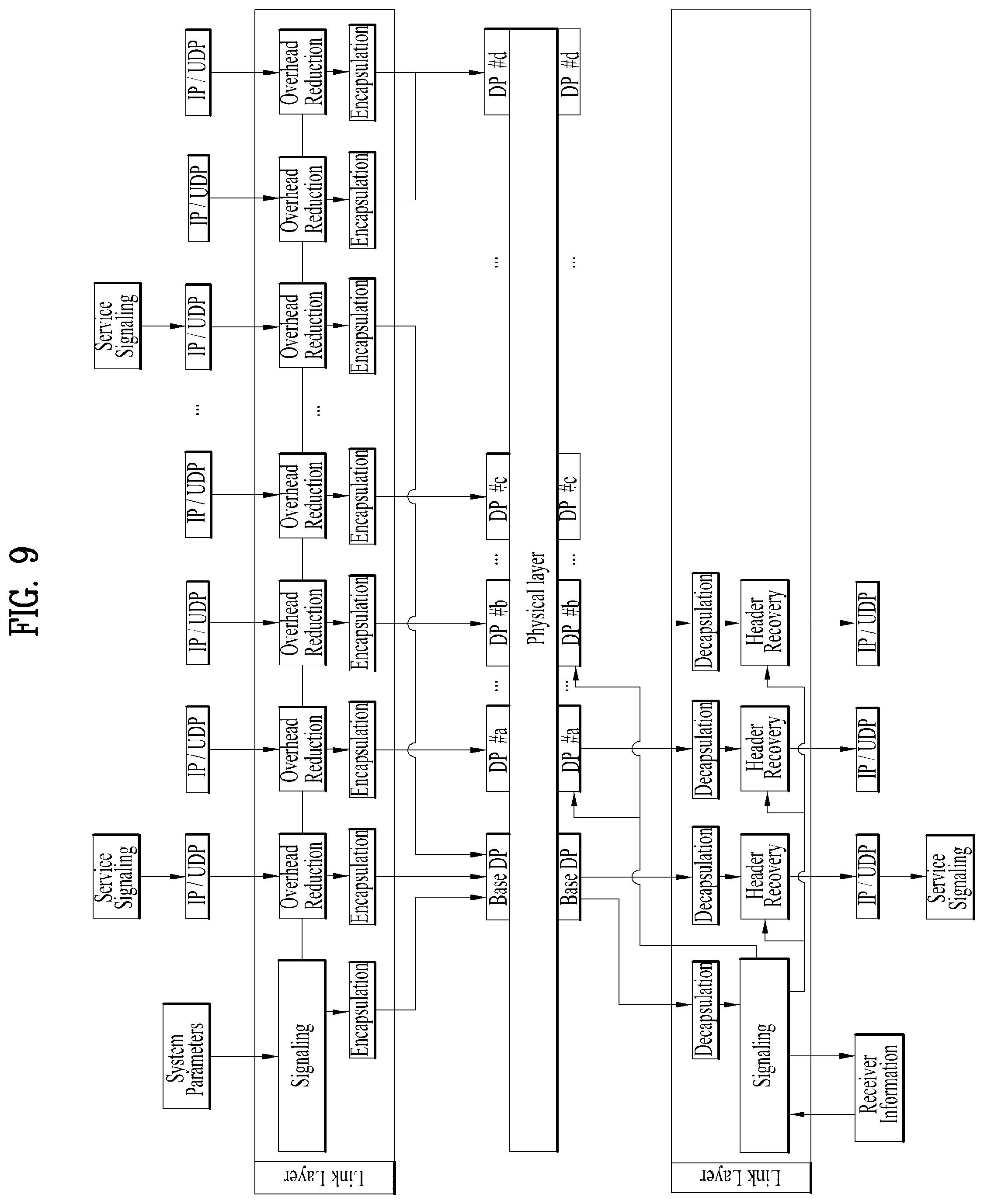
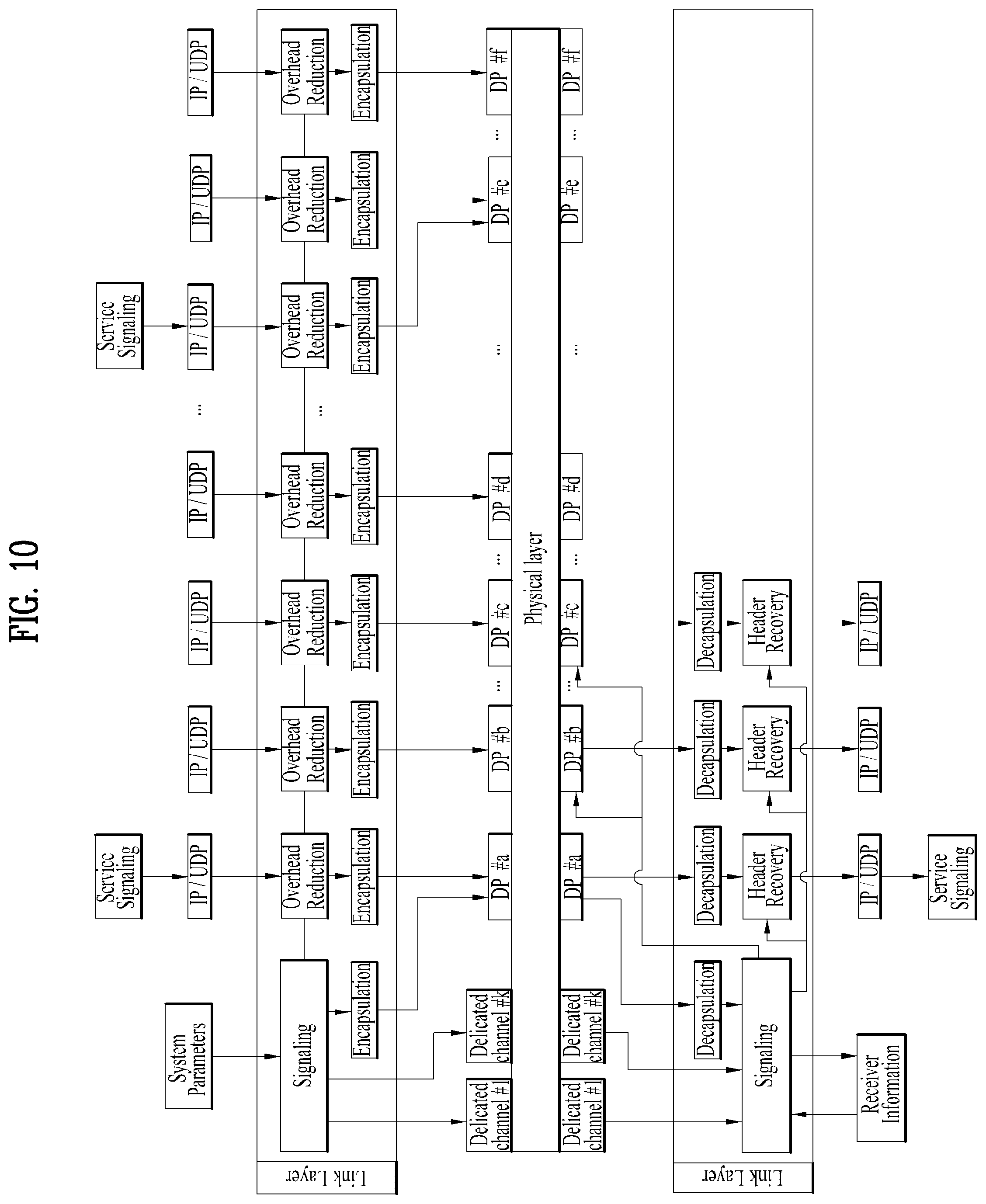
FIG. 9 is a diagram illustrating processing of a broadcast signal when a logical data path includes a normal data pipe and a base data pipe according to an embodiment of the present invention.
The diagram illustrates a structure of a link layer when the logical data path of the physical layer includes a base data pipe and a normal data pipe. As described above, the link layer may include a link layer signaling part, an overhead reduction part, and an encapsulation (decapsulation) part. In this case, a link layer processor for processing a signal and/or data in a link layer may include a link layer signaling processor, an overhead reduction processor, and an encapsulation (decapsulation) processor.
Transmission of information output from each functional module (which may be embodied as hardware or software) to an appropriate data path of the physical layer may be one of main functions of the link layer.
With regard to an IP stream configured on a higher layer of a link layer, a plurality of packet streams may be transmitted according to a data rate at which data is to be transmitted, and overhead reduction and encapsulation procedures may be performed for each respective corresponding packet stream.
A physical layer may include a data pipe (DP) as a plurality of logical data paths that a link layer can access in one frequency band and may transmit a packet stream processed in a link layer for each respective packet stream. When the number of DPs is lower than that of packet streams to be transmitted, some of the packet streams may be multiplexed and input to a DP in consideration of a data rate.
The signaling processor may check transmission system information, related parameters, higher layer signaling, etc. and collect information to be transmitted via signaling. Since a broadcast signal of the physical layer includes a base DP and a normal DP, signaling may be transmitted to the base DP and signaling data may be transmitted in the form of packet appropriate for transmission of the base DP in consideration of a data rate. In this case, signaling may be indicated using a header, etc. of a packet during link layer packet configuration. For example, a header of a link layer packet may include information indicating that data contained in a payload of the packet is signaling data.
In a physical layer structure in which a logical data path such as a base DP exists, it may be efficient to transmit data that is not audio/video content, such as signaling information to the base DP in consideration of a data rate. Accordingly, service signaling that is transmitted in the form of IP packet in a higher layer may be transmitted to the base DP using a method such as IP address filtering, etc. For example, IANA designates an IP address of 224.0.23.60 as ATSC service signaling, an IP packet stream with the corresponding IP address may be transmitted to the base DP.
When a plurality of IP packet streams about corresponding service signaling is present, the IP packet streams may be transmitted to one base DP using a method such as multiplexing, etc. However, a packet about different service signaling may be divided into field values such as a source address and/or a port. In this case, information required for configuration of link layer signaling can also be read from the corresponding service signaling packet.
When a plurality of broadcast services are transmitted through one frequency band, the receiver may not have to decode all DPs, may pre-check signaling information, and may decode only a DP that transmits data and/or a signal about a corresponding service. Accordingly, the receiver may perform the following operation with regard to data and/or processing in a link layer.
When a user selects or changes a service to be received, the receiver tunes a corresponding frequency and reads information of the receiver, stored in a DB, etc. with regard to a corresponding channel. Here, the information stored in the DB, etc. may include information for identification of the base DP.
The receiver decodes the base DP and acquires a link layer signaling packet included in the base DP.
The receiver parses the link layer signaling packet to acquire DP information for reception of the service selected by the user and overhead reduction information about a packet stream of the corresponding DP among a plurality of DPs transmitted through a current channel and overhead reduction information about a packet stream of the corresponding DP. The link layer signaling packet may include information for identification of a DP that transmits a signal and/or data associated with a specific service, and/or information for identification of a type of overhead reduction applied to a packet stream transmitted to the corresponding DP. The receiver may access one or more DPs or restore the packet included in the corresponding DP using the above information.
The receiver is a physical layer processor that processes a signal and/or data according to a protocol of a physical layer, transmits information about a DP to be received for a corresponding service, and receives a packet stream from the corresponding DP.
The receiver performs decapsulation and header recovery on the packet stream decoded in the physical layer and transmits the packet stream to a higher layer of the receiver in the form of IP packet stream.
Then, the receiver performs processing according to a higher layer protocol and provides a broadcast service to the user.
In the above-described process of acquiring the link layer packet by decoding the base DP, information about the base DP (e.g., an identifier (ID) information of the base DP, location information of the base DP, or signaling information included in the base DP) may be acquired during previous channel scan and then stored in a DB and the receiver may use the stored base DP. Alternatively, the receiver may acquire the base DP by first seeking a DP that the receiver has pre-accessed.
In the above-described process of acquiring the DP information for a service selected by the user and the overhead reduction information about a DP packet stream transmitting the corresponding service, by parsing the link layer packet, if the information about the DP transmitting the service selected by the user is transmitted through higher layer signaling (e.g., a layer higher than a link layer, or an IP layer), the receiver may acquire corresponding information from the DB, the buffer, and/or the shared memory as described above and use the acquired information as information about a DP requiring decoding.
If link layer signaling (link layer signaling information) and normal data (e.g., broadcast content data) is transmitted through the same DP or if only a DP of one type is used in a broadcast system, the normal data transmitted through the DP may be temporarily stored in the buffer or the memory while the signaling information is decoded and parsed. Upon acquiring the signaling information, the receiver may transmit a command for extracting a DP that should be obtained according to the corresponding signaling information to a device for extracting and processing the DP by a method using interior command words of the system.
FIG. 10 is a diagram illustrating processing of a broadcast signal when a logical data path includes a normal data pipe and a dedicated channel according to an embodiment of the present invention.
The diagram illustrates a structure of a link layer when the logical data path of the physical layer includes a dedicated channel and a normal data pipe. As described above, the link layer may include a link layer signaling part, an overhead reduction part, and an encapsulation (decapsulation) part. In this regard, a link layer processor to be included in the receiver may include a link layer signaling processor, an overhead reduction processor, and/or an encapsulation (decapsulation) processor. Transmission of information output from each functional module (which may be embodied as hardware or software) to an appropriate data path of the physical layer may be one of main functions of the link layer.
With regard to an IP stream configured on a higher layer of a link layer, a plurality of packet streams may be transmitted according to a data rate at which data is to be transmitted, and overhead reduction and encapsulation procedures may be performed for each respective corresponding packet stream. A physical layer may include a data pipe (DP) as a plurality of logical data paths that a link layer can access in one frequency band and may transmit a packet stream processed in a link layer for each respective packet stream. When the number of DPs is lower than that of packet streams to be transmitted, some of the packet streams may be multiplexed and input to a DP in consideration of a data rate.
The signaling processor may check transmission system information, related parameters, higher layer signaling, etc. and collect information to be transmitted via signaling. In a physical layer structure in which a logical data path such as a dedicate channel exists, it may be efficient to mainly transmit signaling information through a dedicated channel in consideration of a data rate. However, when a large amount of data needs to be transmitted through a dedicated channel, a bandwidth for the dedicated channel corresponding to the amount of the dedicated channel needs to be occupied, and thus it is general to set a high data rate of the dedicated channel. In addition, since a dedicated channel is generally received and decoded at higher speed than a DP, it is more efficient to signaling data in terms of information that needs to be rapidly acquired from the receiver. As necessary, when sufficient signaling data cannot be transmitted through the dedicated channel, signaling data such as the aforementioned link layer signaling packet may be transmitted through the normal DP, and signaling data transmitted through the dedicated channel may include information for identification of the corresponding link layer signaling packet.
A plurality of dedicated channels may exist as necessary and a channel may be enable/disable according to a physical layer.
In the case of service signaling transmitted in the form of IP packet in a higher layer, in general, it is possible to process different IP packets in the same way. However, information of the corresponding IP packet can be read for a configuration of link layer signaling. To this end, a packet including signaling may be found using a filtering method of an IP address. For example, since IANA designates an IP address of 224.0.23.60 as ATSC service signaling, the receiver may check an IP packet having the corresponding IP address use the IP packet for configuration of link layer signaling. In this case, the corresponding packet needs to also be transmitted to a receiver, processing for the IP packet is performed without change.
When a plurality of IP packet streams about service signaling is present, the IP packet streams may be transmitted to one DP together with audio/video data using a method such as multiplexing, etc. However, a packet about service signaling and audio/video data may be divided into field values of an IP address, a port, etc.
When a plurality of broadcast services are transmitted through one frequency band, the receiver does not have to decode all DPs, and it is efficient to pre-check signaling information and to decode only a DP that transmit signal and/or data associated with a required service. Thus, the receiver may perform processing according to a protocol of a link layer as the following procedure.
When a user selects or changes a service to be received, the receiver tunes a corresponding frequency and reads information stored in a DB, etc. with regard to a corresponding channel. The information stored in the DB may include information for identification of a dedicated channel and/or signaling information for acquisition of channel/service/program.
The receiver decodes data transmitted through the dedicated channel and performs processing associated with signaling appropriate for purpose of the corresponding channel. For example, a dedicated channel for transmission of FIC may store and update information such as a service and/or a channel, and a dedicated channel for transmission of EAC may transmit emergency alert information.
The receiver may acquire information of DP to be decoded using information transmitted to the dedicated channel. As necessary, when link layer signaling is transmitted through a DP, the receiver may pre-decode a DP that transmits signaling and transmit the DP to a dedicated channel in order to pre-acquire signaling information. In addition, a packet for link layer signaling may be transmitted through a normal DP, and in this case, the signaling data transmitted through the dedicated channel may include information for identification of a DP including a packet for link layer signaling.
The receiver acquires DP information for reception of a service selected by a user among a plurality of DPs that are transmitted to a current channel and overhead reduction information about a packet stream of the corresponding DP using the link layer signaling information. The link layer signaling information may include information for identification of a DP for transmission of a signal and/or data associated with a specific service, and/or information for identification of a type of overhead reduction applied to a packet stream transmitted to the corresponding DP. The receiver may access one or more DPs for a specific service or restore a packet included in the corresponding DP using the information.
The receiver transmits information for identification of a DP to be received by a physical layer to a physical layer processor that processes a signal and/or data in a physical layer and receives a packet stream from the corresponding DP.
The receiver performs decapsulation and header recovery on a packet stream decoded in a physical layer and transmits the packet stream to a higher layer of the receiver in the form of IP packet stream.
Then the receiver performs processing according to a protocol of a higher layer and provides a broadcast service to the user.
FIG. 11 is a diagram illustrating processing of a broadcast signal when a logical data path includes a normal data pipe, a base data pipe, and a dedicated channel according to an embodiment of the present invention.
The diagram illustrates a structure of a link layer when the logical data path of the physical layer includes a dedicated channel, a base data pipe, and a normal data pipe. As described above, the link layer may include a link layer signaling part, an overhead reduction part, and an encapsulation (decapsulation) part. In this regard, a link layer processor to be included in the receiver may include a link layer signaling processor, an overhead reduction processor, and/or an encapsulation (decapsulation) processor. Transmission of information output from each functional module (which may be embodied as hardware or software) to an appropriate data path of the physical layer may be one of main functions of the link layer.
With regard to an IP stream configured on a higher layer of a link layer, a plurality of packet streams may be transmitted according to a data rate at which data is to be transmitted, and overhead reduction and encapsulation procedures may be performed for each respective corresponding packet stream. A physical layer may include a data pipe (DP) as a plurality of logical data paths that a link layer can access in one frequency band and may transmit a packet stream processed in a link layer for each respective packet stream. When the number of DPs is lower than that of packet streams to be transmitted, some of the packet streams may be multiplexed and input to a DP in consideration of a data rate.
The signaling processor may check transmission system information, related parameters, higher layer signaling, etc. and collect information to be transmitted via signaling. Since a signal of the physical layer includes a base DP and a normal DP, it may be efficient to transmit signaling to the base DP in consideration of a data rate. In this case, the signaling data needs to be transmitted in the form of packet appropriate for transmission through the base DP. Signaling may be indicated using a header, etc. of a packet during link layer packet configuration. That is, a header of a link layer signaling packet including signaling data may include information indicating that signaling data is contained in a payload of the corresponding packet.
In a physical layer structure in which a dedicate channel and a base DP exist simultaneously, signaling information may be divided and transmitted to the dedicated channel and the base DP. In general, since a high data rate of the dedicated channel is not set, signaling information that has a small amount of signaling and needs to be rapidly acquired may be transmitted to the dedicated channel and signaling with a high amount of signaling to the base DP. As necessary, a plurality of dedicated channels may exist and a channel may be enable/disable according to a physical layer. In addition, the base DP may be configured with a separate structure from a normal DP. In addition, it is possible to designate one of normal DPs and use the normal DP as a base DP.
Service signaling that is transmitted in the form of IP packet in a higher layer may be transmitted to the base DP using a method such as IP address filtering, etc. An IP packet stream with a specific IP address and including signaling information may be transmitted to the base DP. When a plurality of IP packet streams about corresponding service signaling is present, the IP packet streams may be transmitted to one base DP using a method such as multiplexing, etc. A packet about different service signaling may be divided into field values such as a source address and/or a port. The receiver may read information required for configuration of the link layer signaling in the corresponding service signaling packet.
When a plurality of broadcast services are transmitted through one frequency band, the receiver may not have to decode all DPs, and it may be efficient to pre-check the signaling information and to decode only a DP that transmits a signal and/or data associated with a required service. Thus, the receiver may perform the following processors as processing according to a protocol of a link layer.
When a user selects or changes a service to be received, the receiver tunes a corresponding frequency and reads information stored in a database DB, etc. with regard to a corresponding channel. The information stored in the DB may include information for identification of a dedicated channel, information for identification of a base data pipe, and/or signaling information for acquisition of channel/service/program.
The receiver decodes data transmitted through the dedicated channel and performs processing associated with signaling appropriate for purpose of the corresponding channel. For example, a dedicated channel for transmission of FIC may store and update information such as a service and/or a channel, and a dedicated channel for transmission of EAC may transmit emergency alert information.
The receiver may acquire information of the base DP using information transmitted to the dedicated channel. The information transmitted to the dedicated channel may include information for identification of the base DP (e.g., an identifier of the base DP and/or an IP address of the base DP). As necessary, the receiver may update signaling information pre-stored in a DB of the receiver and related parameters to information transmitted in the dedicated channel.
The receiver may decode the base DP and acquire a link layer signaling packet. As necessary, the link layer signaling packet may be combined with signaling information received from the dedicated channel. The receiver may find the base DP using the dedicate channel and the signaling information pre-stored in the receiver.
The receiver acquires DP information for reception of a service selected by a user among a plurality of DPs that are transmitted to a current channel and overhead reduction information about a packet stream of the corresponding DP using the link layer signaling information. The link layer signaling information may include information for identification of a DP for transmission of a signal and/or data associated with a specific service, and/or information for identification of a type of overhead reduction applied to a packet stream transmitted to the corresponding DP. The receiver may access one or more DPs for a specific service or restore a packet included in the corresponding DP using the information.
The receiver transmits information for identification of a DP to be received by a physical layer to a physical layer processor that processes a signal and/or data in a physical layer and receives a packet stream from the corresponding DP.
The receiver performs decapsulation and header recovery on a packet stream decoded in a physical layer and transmits the packet stream to a higher layer of the receiver in the form of IP packet stream.
Then the receiver performs processing according to a protocol of a higher layer and provides a broadcast service to the user.
According to an embodiment of the present invention, when information for service signaling is transmitted by one or more IP packet streams, the IP packet streams may be multiplexed and transmitted as one base DP. The receiver may distinguish between packets for different service signaling through a field of a source address and/or a port. The receiver may read out information for acquiring/configuring link layer signaling from a service signaling packet.
In the process of processing signaling information transmitted through the dedicated channel, the receiver may obtain version information of the dedicated channel or information identifying whether update has been performed and, if it is judged that there is no change in the signaling information in the dedicated channel, the receiver may omit processing (decoding or parsing) of the signaling information transmitted through the dedicated channel. If it is confirmed that the dedicated channel has not been updated, the receiver may acquire information of a base DP using prestored information.
In the above-described process of acquiring the DP information for a service selected by the user and the overhead reduction information about the DP packet stream transmitting the corresponding service, if the information about the DP transmitting the service selected by the user is transmitted through higher layer signaling (e.g., a layer higher than a link layer, or an IP layer), the receiver may acquire the corresponding information from the DB, the buffer, and/or the shared memory as described above and use the acquired information as information about a DP requiring decoding.
If link layer signaling (link layer signaling information) and normal data (e.g., broadcast content data) is transmitted through the same DP or if only type of DP is used in a broadcast system, the normal data transmitted through the DP may be temporarily stored in the buffer or the memory while the signaling information is decoded and parsed. Upon acquiring the signaling information, the receiver may transmit a command for extracting a DP that should be obtained according to the corresponding signaling information to a device for extracting and processing the DP by a method using system interior command words.
FIG. 12 is a diagram illustrating a detailed processing operation of a signal and/or data in a link layer of a receiver when a logical data path includes a normal data pipe, a base data pipe, and a dedicated channel according to an embodiment of the present invention.
The present embodiment considers a situation in which one or more services provided by one or more broadcasters are transmitted in one frequency band. It may be considered that one broadcaster transmits one or more broadcast services, one service includes one or more components and a user receives content in units of broadcast services. In addition, some of one or more components included in one broadcast service may be replaced with other components according to user selection.
A fast information channel (FIC) and/or emergency alert channel (EAC) may be transmitted to a dedicated channel. A base DP and a normal DP may be differentiated in a broadcast signal and transmitted or managed. Configuration information of the FIC and/or the EAC may be transmitted through physical layer signaling so as to notify the receiver of the FIC and/or the EAC, and the link layer may format signaling according to the characteristic of the corresponding channel. Transmission of data to a specific channel of a physical layer is performed from a logical point of view and an actual operation may be performed according to the characteristic of a physical layer.
Information about a service of each broadcaster, transmitted in a corresponding frequency, and information about a path for reception of the service may be transmitted through the FIC. To this end, the following information may be provided (signaled) via link layer signaling.
System Parameter--Transmitter related parameter, and/or parameter related to a broadcaster that provides a service in a corresponding channel.
Link layer--which includes context information associated with IP header compression and/or ID of a DP to which corresponding context is applied.
Higher layer--IP address and/or UDP port number, service and/or component information, emergency alert information, and mapping relation information between a DP and an IP address of a packet stream transmitted in an IP layer.
When a plurality of broadcast services is transmitted through one frequency band, a receiver may not have to decode all DPs, and it may be efficient to pre-check signaling information and to decode only a DP about a required service. In a broadcast system, a transmitter may transmit information for identification of only a required DP through an FIC, and the receiver may check a DP to be accessed for a specific serviced, using the FIC. In this case, an operation associated with the link layer of the receiver may be performed as follows.
When a user selects or changes a service to be received by a user, the receiver tunes a corresponding frequency and reads information of a receiver, stored in a DB, etc. in regard to a corresponding channel. The information stored in the DB of the receiver may be configured by acquiring an FIC during initial channel scan and using information included in the FIC.
The receiver may receive an FIC and update a pre-stored DB or acquire information about a component about a service selected by the user and information about a mapping relation for DPs that transmit components from the FIC. In addition, the information about a base DP that transmits signaling may be acquired from the FIC.
When initialization information related to robust header compression (RoHC) is present in signaling transmitted through the FIC, the receiver may acquire the initialization information and prepare header recovery.
The receiver decodes a base DP and/or a DP that transmits a service selected by a user based on information transmitted through the FIC.
The receiver acquires overhead reduction information about a DP that is being received, included in the base DP, performs decapsulation and/or header recovery on a packet stream received in a normal DP using the acquired overhead information, and transmits the packet stream to a higher layer of the receiver in the form of IP packet stream.
The receiver may receive service signaling transmitted in the form of IP packet with a specific address through a base DP and transmit the packet stream to the higher layer with regard to a received service.
When emergency alert occurs, in order to rapidly transmit an emergency alert message to a user, the receiver receives signaling information included in a CAP message through signaling, parses the signaling information, and immediately transmits the signaling information to a user, and finds a path for reception of a corresponding service and receives service data when information of a path through which an audio/video service can be received via signaling can be confirmed. In addition, when information transmitted through a broadband and so on is present, an NRT service and additional information are received using corresponding uniform resource identifier (URI) information and so on. Signaling information associated with emergency alert will be described below in detail.
The receiver processes the emergency alert as follows.
The receiver recognizes a situation in which an emergency alert message is transmitted through a preamble and so on of a physical layer. The preamble of the physical layer may be a signaling signal included in a broadcast signal and may correspond to signaling in the physical layer. The preamble of the physical layer may mainly include information for acquisition of data, a broadcast frame, a data pipe, and/or a transmission parameter that are included in a broadcast signal.
The receiver checks configuration of an emergency alert channel (EAC) through physical layer signaling of the receiver and decodes the EAC to acquire EAT. Here, the EAC may correspond to the aforementioned dedicated channel.
The receiver checks the received EAT, extracts a CAP message, and transmits the CAP message to a CAP parser.
The receiver decodes a corresponding DP and receives service data when service information associated with the emergency alert is present in the EAT. The EAT may include information for identification of a DP for transmitting a service associated with the emergency alert.
When information associated with NRT service data is present in the EAT or the CAP message, the receiver receives the information through a broadband.
FIG. 13 is a diagram illustrating syntax of a fast information channel (FIC) according to an embodiment of the present.
Information included in the FIC may be transmitted in the form of fast information table (FIT).
Information included in the FIT may be transmitted in the form of XML and/or section table.
The FIT may include table_id information, FIT_data_version information, num_broadcast information, broadcast_id information, delivery_system_id information, base_DP_id information, base_DP_version information, num_service information, service_id information, service_category information, service_hidden_flag information, SP_indicator information, num_component information, component_id information, DP_id information, context_id information, RoHC_init_descriptor, context_profile information, max_cid information, and/or large_cid information.
The table_id information indicates that a corresponding table section refers to fast information table.
The FIT_data_version information may indicate version information about syntax and semantics contained in the fast information table. The receiver may determine whether signaling contained in the corresponding fast information table is processed, using the FIT_data_version information. The receiver may determine whether information of pre-stored FIC is updated, using the information.
The num_broadcast information may indicate the number of broadcasters that transmit a broadcast service and/or content through a corresponding frequency or a transmitted transport frame.
The broadcast_id information may indicate a unique identifier of a broadcaster that transmits a broadcast service and/or content through a corresponding frequency or a transmitted transport frame. In the case of a broadcaster that transmits MPEG-2 TS-based data, broadcast_id may have a value such as transport_stream_id of MPEG-2 TS.
The delivery_system_id information may indicate an identifier for a broadcast transmission system that applies and processes the same transmission parameter on a broadcast network that performs transmission.
The base_DP_id information is information for identification of a base DP in a broadcast signal. The base DP may refer to a DP that transmits service signaling including overhead reduction and/or program specific information/system information (PSI/SI) of a broadcaster corresponding to broadcast_id. Alternatively, the base_DP_id information may refer to a representative DP that can decode a component included in a broadcast service in the corresponding broadcaster.
The base_DP_version information may refer to version information about data transmitted through a base DP. For example, when service signaling such as PSI/SI and so on is transmitted through the base DP, if service signaling is changed, a value of the base_DP_version information may be increased one by one.
The num_service information may refer to the number of broadcast services transmitted from a broadcaster corresponding to the broadcast_id in a corresponding frequency or a transport frame.
The service_id information may be used as an identifier for identification of a broadcast service.
The service_category information may refer to a category of a broadcast service. According to a value of a corresponding field, the service_category information may have the following meaning. When a value of the service_category information is 0.times.01, the service_category information may refer to a basic TV, when the value of the service_category information is 0.times.02, the service_category information may refer to a basic radio, when the value of the service_category information is 0.times.03, the service_category information may refer to an RI service, when the value of the service_category information is 0.times.08, the service_category information may refer to a service guide, and when the value of the service_category information is 0.times.09, the service_category information may refer to emergency alerting.
The service_hidden_flag information may indicate whether a corresponding broadcast service is hidden. When the service is hidden, the broadcast service may be a test service or a self-used service and may be processed to be disregarded or hidden from a service list by a broadcast receiver.
The SP_indicator information may indicate whether service protection is applied to one or more components in a corresponding broadcast service.
The num_component information may indicate the number of components included in a corresponding broadcast service.
The component_id information may be used as an identifier for identification of a corresponding component in a broadcast service.
The DP_id information may be used as an identifier indicating a DP that transmits a corresponding component.
The RoHC_init_descriptor may include information associated with overhead reduction and/or header recovery. The RoHC_init_descriptor may include information for identification of a header compression method used in a transmission terminal.
The context_id information may represent a context corresponding to a following RoHC related field. The context_id information may correspond to a context identifier (CID).
The context_profile information may represent a range of a protocol for compression of a header in RoHC. When a compressor and a decompressor have the same profile, it is possible to compress and restore a stream in the RoHC.
The max_cid information is used for indicating a maximum value of a CID to a decompressor.
The large_cid information has a boolean value and indicates whether a short CID (0 to 15) or an embedded CID (0 to 16383) is used for CID configuration. Accordingly, the sized of byte for representing the CID is determined together.
FIG. 14 is a diagram illustrating syntax of an emergency alert table (EAT) according to an embodiment of the present invention.
Information associated with emergency alert may be transmitted through the EAC. The EAC may correspond to the aforementioned dedicated channel.
The EAT according to an embodiment of the present invention may include EAT_protocol_version information, automatic_tuning_flag information, num_EAS_messages information, EAS_message_id information, EAS_IP_version_flag information, EAS_message_transfer_type information, EAS_message_encoding_type information, EAS_NRT_flag information, EAS_message_length information, EAS_message_byte information, IP_address information, UDP_port_num information, DP_id information, automatic_tuning_channel_number information, automatic_tuning_DP_id information, automatic_tuning_service_id information, and/or EAS_NRT_service_id information.
The EAT_protocol_version information indicates a protocol version of received EAT.
The automatic_tuning_flag information indicates whether a receiver automatically performs channel conversion.
The num_EAS_messages information indicates the number of messages contained in the EAT.
The EAS_message_id information is information for identification of each EAS message.
The EAS_IP_version_flag information indicates IPv4 when a value of the EAS_IP_version_flag information is 0, and indicates IPv6 when a value of the EAS_IP_version_flag information is 1.
The EAS_message_transfer_type information indicates the form in which an EAS message is transmitted. When a value of the EAS_message_transfer_type information is 000, the EAS_message_transfer_type information indicates a not specified state, when a value of the EAS_message_transfer_type information is 001, the EAS_message_transfer_type information indicates a no alert message (only AV content), and when a value of the EAS_message_transfer_type information is 010, the EAS_message_transfer_type information indicates that an EAS message is contained in corresponding EAT. To this end, a length field and a field about the corresponding EAS message are added. When a value of the EAS_message_transfer_type information is 011, the EAS message transfer type information indicates that the EAS message is transmitted through a data pipe. The EAS may be transmitted in the form of IP datagram in a data pipe. To this end, IP address, UDP port information, and DP information of a transmitted physical layer may be added.
The EAS_message_encoding_type information indicates information about an encoding type of an emergence alert message. For example, when a value of the EAS_message_encoding_type information is 000, the EAS_message_encoding_type information indicates a not specific state, when a value of the EAS_message_encoding_type information is 001, the EAS_message_encoding_type information indicates No Encoding, when a value of the EAS_message_encoding_type information is 010, the EAS_message_encoding_type information indicates DEFLATE algorithm (RFC1951), and 001 to 111 among values of the EAS_message_encoding_type information may be reserved for other encoding types.
The EAS_NRT_flag information indicates whether NRT contents and/or NRT data associated with a received message is present. When a value of the EAS_NRT_flag information is 0, the EAS_NRT_flag information indicates that NRT contents and/or NRT data associated with a received emergency message is not present, and when a value of the EAS_NRT_flag information is 1, the EAS_NRT_flag information indicates that NRT contents and/or NRT data associated with a received emergency message is present.
The EAS_message_length information indicates a length of an EAS message.
The EAS_message_byte information includes content of an EAS message.
The IP_address information indicates an IP address of an IP address for transmission of an EAS_message.
The UDP_port_num information indicates a UDP port number for transmission of an EAS_message.
The DP_id information identifies a data pipe that transmits an EAS_message.
The automatic_tuning_channel_number information includes information about a number of a channel to be converted.
The automatic_tuning_DP_id information is information for identification of a data pipe that transmits corresponding content.
The automatic_tuning_service_id information is information for identification of a service to which corresponding content belongs.
The EAS_NRT_service_id information is information for identification of an NRT service corresponding to the case in which NRT contents and data associated with a received emergency alert message and transmitted, that is, the case in which an EAS_NRT_flag is enabled.
FIG. 15 is a diagram illustrating a packet transmitted to a data pipe according to an embodiment of the present invention.
According to an embodiment of the present invention, configuration of a packet in a link layer is newly defined so as to generate a compatible link layer packet irrespective of change in protocol of a higher layer or the link layer or a lower layer of the link layer.
The link layer packet according to an embodiment of the present invention may be transmitted to a normal DP and/or a base DP.
The link layer packet may include a fixed header, an expansion header, and/or a payload.
The fixed header is a header with a fixed size and the expansion header is a header, the size of which can be changed according to configuration of the packet of the higher layer. The payload is a region in which data of the higher layer is transmitted.
A header (the fixed header or the expansion header) of a packet may include a field indicating a type of the payload of the packet. In the case of the fixed header, first 3 bits (packet type) of 1 byte may include data for identification of a packet type of the higher layer, and the remaining 5 bits may be used as an indicator part. The indicator part may include data for identification of a configuring method of a payload and/or configuration information of the expansion header and may be changed according to a packet type.
A table shown in the diagram represents a type of a higher layer included in a payload according to a value of a packet type.
According to system configuration, an IP packet and/or an RoHC packet of the payload may be transmitted through a DP, and a signaling packet may be transmitted through a base DP. Accordingly, when a plurality of packets are mixed and transmitted, packet type values may also be applied so as to differentiate a data packet and a signaling packet.
When a packet type value is 000, an IP packet of IPv4 is included in a payload.
When a packet type value is 001, an IP packet of IPv6 is included in a payload.
When a packet type value is 010, a compressed IP packet is included in a payload. The compressed IP packet may include an IP packet to which header compression is applied.
When a packet type value is 110, a packet including signaling data is included in a payload.
When a packet type value is 111, a framed packet type is included in a payload.
FIG. 16 is a diagram illustrating a detailed processing operation of a signal and/or data in each protocol stack of a transmitter when a logical data path of a physical layer includes a dedicated channel, a base DP, and a normal data DP, according to another embodiment of the present invention.
In one frequency band, one or more broadcasters may provide broadcast services. A broadcaster transmits multiple broadcast services and one broadcast service may include one or more components. A user may receive content in units of broadcast services.
In a broadcast system, a session-based transmission protocol may be used to support IP hybrid broadcast and the contents of signaling delivered to each signaling path may be determined according to the structure of the corresponding transmission protocol.
As described above, data related to the FIC and/or the EAC may be transmitted/received over the dedicated channel. In the broadcast system, a base DP and a normal DP may be used to distinguish therebetween.
Configuration information of the FIC and/or EAC may be included in physical layer signaling (or a transmission parameter). A link layer may format signaling according to characteristics of a corresponding channel. Transmission of data to a specific channel of a physical layer may be performed from a logical point of view and actual operation may be performed according to characteristics of a physical layer.
The FIC may include information about services of each broadcaster, transmitted in a corresponding frequency and information about paths for receiving the services. The FIC may include information for service acquisition and may be referred to as service acquisition information.
The FIC and/or the EAC may be included in link layer signaling.
Link layer signaling may include the following information.
System Parameter--A parameter related to a transmitter or a parameter related to a broadcaster that provides a service in a corresponding channel.
Link layer--Context information associated with IP header compression and an ID of a DP to which a corresponding context is applied.
Higher layer--IP address and UDP port number, service and component information, emergency alert information, and a mapping relationship between an ID address, a UDP port number, a session ID, and a DP of a packet stream and signaling transmitted in an IP layer.
As described above, one or more broadcast services are transmitted in one frequency band, the receiver does not need to decode all DPs and it is efficient to pre-check signaling information and to decode only a DP related to a necessary service.
In this case, referring to the drawing, the broadcast system may provide and acquire information for mapping a DP and a service, using the FIC and/or the base DP.
A process of processing a broadcast signal or broadcast data in a transmitter of the drawing will now be described. One or more broadcasters (broadcasters #1 to # N) may process component signaling and/or data for one or more broadcast services so as to be transmitted through one or more sessions. One broadcast service may be transmitted through one or more sessions. The broadcast service may include one or more components included in the broadcast service and/or signaling information for the broadcast service. Component signaling may include information used to acquire components included in the broadcast service in a receiver. Service signaling, component signaling, and/or data for one or more broadcast services may be transmitted to a link layer through processing in an IP layer.
In the link layer, the transmitter performs overhead reduction when overhead reduction for an IP packet is needed and generates related information as link layer signaling. Link layer signaling may include a system parameter specifying the broadcast system, in addition to the above-described information. The transmitter may process an IP packet in a link layer processing procedure and transmit the processed IP packet to a physical layer in the form of one or more DPs.
The transmitter may transmit link layer signaling to the receiver in the form or configuration of an FIC and/or an EAC. Meanwhile, the transmitter may also transmit link layer signaling to the base DP through an encapsulation procedure of the link layer.
FIG. 17 is a diagram illustrating a detailed processing operation of a signal and/or data in each protocol stack of a receiver when a logical data path of a physical layer includes a dedicated channel, a base DP, and a normal data DP, according to another embodiment of the present invention.
If a user selects or changes a service desired to be received, a receiver tunes to a corresponding frequency. The receiver reads information stored in a DB etc. in association with a corresponding channel. The information stored in the DB etc. of the receiver may be information included upon acquiring an FIC and/or an EAC during initial channel scan. Alternatively, the receiver may extract transmitted information as described above in this specification.
The receiver may receive the FIC and/or the EAC, receive information about a channel that the receiver desires to access, and then update information pre-stored in the DB. The receiver may acquire components for a service selected by a user and information about a mapping relationship of a DP transmitted by each component or acquire a base DP and/or a normal DP through which signaling necessary to obtain such information is transmitted. Meanwhile, when it is judged that there is no change in corresponding information using version information of the FIC or information identifying whether to require additional update of a dedicated channel, the receiver may omit a procedure of decoding or parsing the received FIC and/or EAC.
The receiver may acquire a link layer signaling packet including link layer signaling information by decoding a base DP and/or a DP through which signaling information is transmitted, based on information transmitted through the FIC. The receiver may use, when necessary, the received link layer signaling information by a combination with signaling information (e.g., receiver information in the drawing) received through the dedicated channel.
The receiver may acquire information about a DP for receiving a service selected by the user among multiple DPs that are being transmitted over a current channel and overhead reduction information about a packet stream of the corresponding DP, using the FIC and/or the link layer signaling information.
When the information about the DP for receiving the selected service is transmitted through higher layer signaling, the receiver may acquire signaling information stored in the DB and/or the shared memory as described above and then acquire information about a DP to be decoded, indicated by the corresponding signaling information.
When the link layer signaling information and normal data (e.g., data included in broadcast content) are transmitted through the same DP or only one DP is used for transmission of the link layer signaling information and normal data, the receiver may temporarily store the normal data transmitted through the DP in a device such as a buffer while the signaling information is decoded and/or parsed.
The receiver may acquire the base DP and/or the DP through which the signaling information is transmitted, acquire overhead reduction information about a DP to be received, perform decapsulation and/or header recovery for a packet stream received in a normal DP, using the acquired overhead information, process the packet stream in the form of an IP packet stream, and transmit the IP packet stream to a higher layer of the receiver.
FIG. 18 is a diagram illustrating a syntax of an FIC according to another embodiment of the present invention.
Information included in the FIC described in this drawing may be selectively combined with other information included in the FIC and may configure the FIC.
The receiver may rapidly acquire information about a channel, using the information included in the FIC. The receiver may acquire bootstrap related information using the information included in the FIC. The FIC may include information for fast channel scan and/or fast service acquisition. The FIC may be referred to by other names, for example, a service list table or service acquisition information. The FIC may be transmitted by being included in an IP packet in an IP layer according to a broadcast system. In this case, an IP address and/or a UDP port number, transmitting the FIC, may be fixed to specific values and the receiver may recognize that the IP packet transmitted with the corresponding IP address and/or UDP port number includes the FIC, without an additional processing procedure.
The FIC may include FIC_protocol_version_information, transport_stream_id information, num_partitions information, partition_id information, partition_protocol_version information, num_services information, service_id information, service_data_version information, service_channel_number information, service_category information, service_status information, service_distribution information, sp_indicator information, IP_version_flag information, SSC_source_P_address_flag information, SSC_source_IP_address information, SSC_destination_IP_address information, SSC_destination_UDP_port information, SSC_TSI information, SSC_DP_ID information, num_partition_level_descriptors information, partition_level_descriptor( ) information, num_FIC_level_descriptors information, and/or FIC_level_descriptor( ) information.
FIC_protocol_version information represents a version of a protocol of an FIC.
transport_stream_id information identifies a broadcast stream. transport_stream_id information may be used as information for identifying a broadcaster.
num_partitions information represents the number of partitions in a broadcast stream. The broadcast stream may be transmitted after being divided into one or more partitions. Each partition may include one or more DPs. The DPs included in each partition may be used by one broadcaster. In this case, the partition may be defined as a data transmission unit allocated to each broadcaster.
partition_id information identifies a partition. partition_id information may identify a broadcaster.
partition_protocol_version information represents a version of a protocol of a partition.
num_services information represents the number of services included in a partition. A service may include one or more components.
service_id information identifies a service.
service_data_version information represents change when a signaling table (signaling information) for a service is changed or a service entry for a service signaled by an FIC is changed. service_data_version information may increment a value thereof whenever such change is present.
service_channel_number information represents a channel number of a service.
service_category information represents a category of a service. The category of a service includes A/V content, audio content, an electronic service guide (ESG), and/or content on demand (CoD).
service_status information represents a state of a service. A state of a service may include an active or suspended state and a hidden or shown state. The state of a service may include an inactive state. In the inactive state, broadcast content is not currently provided but may be provided later. Accordingly, when a viewer scans a channel in a receiver, the receiver may not show a scan result for a corresponding service to the viewer.
service_distribution information represents a distribution state of data for a service. For example, service_distribution information may represent that entire data of a service is included in one partition, partial data of a service is not included in a current partition but content is presentable only by data in this partition, another partition is needed to present content, or another broadcast stream is needed to present content.
sp_indicator information identifies whether service protection has been applied. sp_indicator information may identify, for example, for meaningful presentation, whether one or more necessary components are protected (e.g., a state in which a component is encrypted).
IP_version_flag information identifies whether an IP address indicated by SSC_source_IP_address information and/or SSC_destination_IP_address information is an IPv4 address or an IPv6 address.
SSC_source_IP_address_flag information identifies whether SSC_source_IP_address information is present.
SSC_source_IP_address information represents a source IP address of an IP datagram that transmits signaling information for a service. The signaling information for a service may be referred to as service layer signaling. Service layer signaling includes information specifying a broadcast service. For example, service layer signaling may include information identifying a data unit (a session, a DP, or a packet) that transmits components constituting a broadcast service.
SSC_destination_IP_address information represents a destination IP address of an IP datagram (or channel) that transmits signaling information for a service.
SSC_destination_UDP_port information represents a destination UDP port number for a UDP/IP stream that transmits signaling information for a service.
SSC_TSI information represents a transport session identifier (TSI) of an LCT channel (or session) that transmits signaling information (or a signaling table) for a service.
SSC_DP_ID information represents an ID for identifying a DP including signaling information (or a signaling table) for a service. As a DP including the signaling information, the most robust DP in a broadcast transmission process may be allocated.
num_partition_level descriptor( ) information identifies the number of descriptors of a partition level for a partition.
partition_level_descriptor( ) information includes zero or more descriptors that provide additional information for a partition.
num_FIC_level_descriptors information represents the number of descriptors of an FIC level for an FIC.
FIC_level_descriptor( ) information includes zero or more descriptors that provide additional information for an FIC.
FIG. 19 is a diagram illustrating signaling_Information_Part( ) according to an embodiment of the present invention.
A broadcast system may add additional information to an extended header part in the case of a packet for transmitting signaling information in a structure of a packet transmitted through the above-described DP. Such additional information will be referred to as Signaling_Information_Part( ).
Signaling_Information_Part( ) may include information used to determine a processing module (or processor) for received signaling information. In a system configuration procedure, the broadcast system may adjust the number of fields indicating information and the number of bits allocated to each field, in a byte allocated to Signaling_Information_Part( ). When signaling information is transmitted through multiplexing, a receiver may use information included in Signaling_Information_Part( ) to determine whether corresponding signaling information is processed and determine to which signaling processing module signaling information should be transmitted.
Signaling_Information_Part( ) may include Signaling_Class information, Information_Type information, and/or signaling format information.
Signaling_Class information may represent a class of transmitted signaling information. Signaling information may correspond to an FIC, an EAC, link layer signaling information, service signaling information, and/or higher layer signaling information. Mapping for a class of signaling information indicated by each value of configuration of the number of bits of a field of Signaling_Class information may be determined according to system design.
Information_Type information may be used to indicate details of signaling information identified by signaling class information. Meaning of a value indicated by Information_Type information may be additionally defined according to class of signaling information indicated by Signaling_Class information.
Signaling format information represents a form (or format) of signaling information configured in a payload. The signaling format information may identify formats of different types of signaling information illustrated in the drawing and identify a format of additionally designated signaling information.
Signaling_Information_Part( ) of (a) and (b) illustrated in the drawing is one embodiment and the number of bits allocated to each field thereof may be adjusted according to characteristics of the broadcast system.
Signaling_Information_Part( ) as in (a) of the drawing may include signaling class information and/or signaling format information. Signaling_Information_Part( ) may be used when a type of signaling information need not be designated or an information type can be judged in signaling information. Alternatively, when only one signaling format is used or when an additional protocol for signaling is present so that signaling formats are always equal, only a 4-bit signaling class field may be used without configuring a signaling field and the other fields may be reserved for later use or an 8-bit signaling class maybe configured to support various types of signaling.
Signaling_Information_Part( ) as in (b) of the drawing may further include information type information for indicating a type or characteristic of more detailed information in a signaling class when the signaling class is designated and may also include signaling format information. Signaling class information and information type information may be used to determine decapsulation of signaling information or a processing procedure of corresponding signaling. A detailed structure or processing of link layer signaling may refer to the above description and a description which will be given below.
FIG. 20 is a diagram illustrating a procedure for controlling an operation mode of a transmitter and/or a receiver in a link layer according to an embodiment of the present invention.
When the operation mode of the transmitter or the receiver of the link layer is determined, a broadcast system can be more efficiently used and can be flexibly designed. The method of controlling the link layer mode proposed according to the present invention can dynamically convert a mode of a link layer in order to efficiently manage a system bandwidth and processing time. In addition, the method of controlling the link layer mode according to the present invention may easily cope with the case in which a specific mode needs to be supported due to change in a physical layer or on the other hand, the specific mode does not have to be changed any more. In addition, the method of controlling the link layer mode according to the present invention may also allow a broadcast system to easily satisfy requirements of a corresponding broadcaster when a broadcaster providing a broadcast service intends to designate a method of transmitting a corresponding service.
The method of controlling the mode of the link layer may be configured to be performed only in a link layer or to be performed via change in data configuration in the link layer. In this case, it is possible to perform an independent operation of each layer in a network layer and/or a physical layer without embodiment of a separate function. In the mode of the link layer proposed according to the present invention, it is possible to control the mode with signaling or parameters in a system without changing a system in order to satisfy configuration of a physical layer. A specific mode may be performed only when processing of corresponding input is supported in a physical layer.
The diagram is a flowchart illustrating processing of signal and/or data in an IP layer, a link layer, and a physical layer by a transmitter and/or a receiver.
A function block (which may be embodied as hardware and/or software) for mode control may be added to the link layer and may manage parameter and/or signaling information for determination of whether a packet is processed. The link layer may determine whether a corresponding function is performed during processing of a packet stream using information of a mode control functional block.
First, an operation of the transmitter will be described.
When an IP is input to a link layer, the transmitter determines whether overhead reduction (j16020) is performed using a mode control parameter (j16005). The mode control parameter may be generated by a service provider in the transmitter. The mode control parameter will be described below in detail.
When the overhead reduction (j16020) is performed, information about overhead reduction is generated and is added to link layer signaling (j16060) information. The link layer signaling (j16060) information may include all or some of mode control parameters. The link layer signaling (j16060) information may be transmitted in the form of link layer signaling packet. The link layer signaling packet may be mapped to a DP and transmitted to the receiver, but may not be mapped to the DP and may be transmitted to the receiver in the form of link layer signaling packet through a predetermined region of a broadcast signal.
A packet stream on which the overhead reduction (j16020) is performed is encapsulated (j16030) and input to a DP of a physical layer (j16040). When overhead reduction is not performed, whether encapsulation is performed is re-determined (j16050).
A packet stream on which the encapsulation (j16030) is performed is input to a DP (j16040) of a physical layer. In this case, the physical layer performs an operation for processing a general packet (a link layer packet). When overhead reduction and encapsulation are not performed, an IP packet is transmitted directly to a physical layer. In this case, the physical layer performs an operation for processing the IP packet. When the IP packet is directly transmitted, a parameter may be applied to perform the operation only when the physical layer support IP packet input. That is, a value of a mode control parameter may be configured to be adjusted such that a process of transmitting an IP packet directly to a physical layer is not performed when the physical layer does not support processing of an IP packet.
The transmitter transmits a broadcast signal on which this process is performed, to the receiver.
An operation of the receiver will be described below.
When a specific DP is selected for the reason such channel change and so on according to user manipulation and a corresponding DP receives a packet stream (j16110), the receiver may check a mode in which a packet is generated, using a header and/or signaling information of the packet stream (j16120). When the operation mode during transmission of the corresponding DP is checked, decapsulation (j16130) and overhead reduction (j16140) processes are performed through a receiving operating process of a link layer and then an IP packet is transmitted to a higher layer. The overhead reduction (j16140) process may include an overhead recovery process.
FIG. 21 is a diagram illustrating an operation in a link layer according to a value of a flag and a type of a packet transmitted to a physical layer according to an embodiment of the present invention.
In order to determine an operation mode of the link layer, the aforementioned signaling method may be used. Signaling information associated with the method may be transmitted directly to a receiver. In this case, the aforementioned signaling data or link layer signaling packet may include mode control that will be described below and related information.
In consideration of the complexity of the receiver, an operation mode of the link layer may be indirectly indicated to the receiver.
The following two flags may be configured with regard to control of an operation mode.
Header compression flag (HCF): This may be a flag for determination of whether header compression is applied to a corresponding link layer and may have a value indicating enable or disable.
Encapsulation flag (EF): This may be a flag for determination of whether encapsulation is applied in a corresponding link layer and may have a value indicating enable or disable. However, when encapsulation needs to be performed according to a header compression scheme, the EF may be defined to be dependent upon a HCF.
A value mapped to each flag may be applied according to system configuration as long as the value represents Enable and Disable, and a bit number allocated to each flag can be changed. According to an embodiment of the present invention, an enable value may be mapped to 1 and a disable value may be mapped to 0.
The diagram shows whether header compression and encapsulation included in a link layer are performed according to values of HCF and EF and in this case, a packet format transmitted to a physical layer. That is, according to an embodiment of the present invention, the receiver can know a type of a packet input to the physical layer as information about the HCF and the EF.
FIG. 22 is a diagram a descriptor for signaling a mode control parameter according to an embodiment of the present invention.
Flags as information about mode control in a link layer may be signaling information, generated by the transmitter in the form of descriptor, and transmitted to the receiver. Signaling including a flag as information about mode control may be used to control an operation mode in a transmitter of a headend terminal, and whether a flag as information about mode control is included in signaling transmitted to the receiver may be optionally selected.
When signaling including a flag as information about mode control is transmitted to the receiver, the receiver may directly select an operation mode about a corresponding DP and perform a packet decapsulation operation. When signaling including a flag as information about mode control is not transmitted to the receiver, the receiver can determine a mode in which the signaling is transmitted, using physical layer signaling or field information of a packet header, which is transmitted to the receiver.
The link layer mode control description according to an embodiment of the present invention may include DP_id information, HCF information, and/or EF information. The link layer mode control description may be included in a transmission parameter in the aforementioned FIC, link layer signaling packet, signaling via a dedicated channel, PSI/SI, and/or physical layer.
The DP_id information identifies a DP to which a mode in a link layer is applied.
The HCF information identifies whether header compression is applied in the DP identified by the DP_id information.
The EF information identifies whether encapsulation is performed on the DP identified by the DP_id information.
FIG. 23 is a diagram illustrating an operation of a transmitter for controlling an operation mode according to an embodiment of the present invention.
Although not illustrated in the diagram, prior to a processing process of al ink layer, a transmitter may perform processing in a higher layer (e.g., an IP layer). The transmitter may generate an IP packet including broadcast data for a broadcast service.
The transmitter parses or generates a system parameter (JS19010). Here, the system parameter may correspond to the aforementioned signaling data and signaling information.
The transmitter may receive or set mode control related parameter or signaling information during a broadcast data processing process in a link layer and sets a flag value associated with operation mode control (JS19020). The transmitter may perform this operation after the header compression operation or the encapsulation operation. That is, the transmitter may perform the header compression or encapsulation operation and generate information associated with this operation.
The transmitter acquires a packet of a higher layer that needs to be transmitted through a broadcast signal (JS19030). Here, the packet of the higher layer may correspond to an IP packet.
The transmitter checks HCF in order to determine whether header compression is applied to the packet of the higher layer (JS19040).
When the HCF is enabled, the transmitter applies the header compression to the packet of the higher layer (JS19050). After header compression is performed, the transmitter may generate the HCF. The HCF may be used to signal whether header compression is applied, to the receiver.
The transmitter performs encapsulation on the packet of the higher layer to which header compression is applied to generate a link layer packet (JS19060). After the encapsulation process is performed, the transmitter may generate an EF. The EF may be used to signal whether encapsulation is applied to the higher layer packet, to the receiver.
The transmitter transmits the link layer packet to a physical layer processor (JS19070). Then the physical layer processor generates a broadcast signal including the link layer packet and transmits the broadcast signal to the receiver.
When the HCF is disabled, the transmitter checks the EF in order to determine whether encapsulation is applied (JS19080).
When the EF is enabled, the transmitter performs encapsulation on the higher layer packet (JS19090). When the EF is disabled, the transmitter does not perform separate processing on the corresponding packet stream. The transmitter transmits the packet stream (link layer packet) on which processing is completed in the link layer, to a physical layer (JS19070). Header compression, encapsulation, and/or generation of link layer may be performed by a link layer packet generator (i.e. link layer processor) in the transmitter.
The transmitter may generate service signaling channel (SCC) data. The service signaling channel data may be generated by a service signaling data encoder. The service signaling data encoder may be included in a link layer processor and may present separately from the link layer processor. The service signaling channel data may include the aforementioned FIC and/or EAT. The service signaling channel data may be transmitted to the aforementioned dedicated channel.
FIG. 24 is a diagram illustrating an operation of a receiver for processing a broadcast signal according to an operation mode according to an embodiment of the present invention.
A receiver may receive information associated with an operation mode in a link layer together with a packet stream.
The receiver receives signaling information and/or channel information (JS20010). Here, a description of the signaling information and/or the channel information is replaced with the above description.
The receiver selects a DP for receiving and processing according to the signaling information and/or the channel information (JS20020).
The receiver performs decoding of a physical layer on the selected DP and receives a packet stream of a link layer (JS20030).
The receiver checks whether link layer mode control related signaling is included in the received signaling (JS20040).
When the receiver receives the link layer mode related information, the receiver checks an EF (JS20050).
When the EF is enabled, the receiver performs a decapsulation process on a link layer packet (JS20060).
The receiver checks an HCF after decapsulation of the packet, and performs a header decompression process when the HCF is enabled (JS20080).
The receiver transmits the packet on which header decompression is performed, to a higher layer (e.g., an IP layer) (JS20090). During the aforementioned process, when the HCF and the EF are disabled, the receiver recognizes the processed packet stream as an IP packet and transmits the corresponding packet to the IP layer.
When the receiver does not receive link layer mode related information or a corresponding system does not transmit the link layer mode related information to the receiver, the following operation is performed.
The receiver receives signaling information and/or channel information (JS20010) and selects a DP for reception and processing according to corresponding information (JS20020). The receiver performs decoding of the physical layer on the selected DP to acquire a packet stream (JS20030).
The receiver checks whether the received signaling includes link layer mode control related signaling (JS20040).
Since the receiver does not receive link layer mode related signaling, the receiver checks a format of the packet transmitted using physical layer signaling, etc. (JS20100). Here, the physical layer signaling information may include information for identification of a type of the packet included in a payload of the DP. When the packet transmitted from the physical layer is an IP packet, the receiver transmits the packet to the IP layer without a separate process in a link layer.
When a packet transmitted from a physical layer is a packet on which encapsulation is performed, the receiver performs a decapsulation process on the corresponding packet (JS20110).
The receiver checks the form of a packet included in a payload using information such as a header, etc. of the link layer packet during the decapsulation process (JS20120), and the receiver transmits the corresponding packet to the IP layer processor when the payload is an IP packet.
When the payload of the link layer packet is a compressed IP, the receiver performs a decompression process on the corresponding packet (JS20130).
The receiver transmits the IP packet to an IP layer processor (JS20140).
FIG. 25 is a diagram illustrating information for identifying an encapsulation mode according to an embodiment of the present invention.
In a broadcast system, when processing in a link layer operates in one or more modes, a procedure for determining as which mode processing in the link layer operates (in a transmitter and/or a receiver) may be needed. In a procedure of establishing a transmission link between the transmitter and the receiver, the transmitter and/or the receiver may confirm configuration information of the link layer. This case may correspond to the case in which the receiver is initially set up or performs a scan procedure for a service or a mobile receiver newly enters an area within a transmission radius of the transmitter. This procedure may be referred to as an initialization procedure or a bootstrapping procedure. This procedure may be configured as a partial process of a procedure supported by the system without being configured by an additional procedure. In this specification, this procedure will be referred to as an initialization procedure.
Parameters needed in the initialization procedure may be determined according to functions supported by a corresponding link layer and types of operating modes possessed by each function. A description will be given hereinafter of the parameters capable of determining functions constituting the link layer and operation modes according to the functions.
The above-described drawing illustrates parameters for identifying an encapsulation mode.
When a procedure for encapsulating a packet in a link layer or a higher layer (e.g., an IP layer) can be configured, indexes are assigned to respective encapsulation modes and a proper field value may be allocated to each index. The drawing illustrates an embodiment of a field value mapped to each encapsulation mode. While it is assumed that a 2-bit field value is assigned in this embodiment, the field value may be expanded within a range permitted by the system in actual implementation, when more supportable encapsulation modes are present.
In this embodiment, if a field of information indicating an encapsulation mode is set to `00`, the corresponding information may represent that encapsulation in a link layer is bypasses and not performed. If a field of information indicating an encapsulation mode is set to `01`, the corresponding information may represent that data is processed by a first encapsulation scheme in the link layer. If a field of information indicating an encapsulation mode is set to `10`, the corresponding information may represent that data is processed by a second encapsulation scheme in the link layer. If a field of information indicating an encapsulation mode is set to `11`, the corresponding information may represent that data is processed by a third encapsulation scheme in the link layer.
FIG. 26 is a diagram illustrating information for identifying a header compression mode according to an embodiment of the present invention.
Processing in a link layer may include a function of header compression of an IP packet. If a few IP header compression schemes are capable of being supported in the link layer, a transmitter may determine which scheme the transmitter is to use.
Determination of a header compression mode generally accompanies an encapsulation function. Therefore, when the encapsulation mode is disabled, the header compression mode may also be disabled. The above-described drawing illustrates an embodiment of a field value mapped to each header compression mode. While it is assumed that a 3-bit field value is assigned in this embodiment, the field value may be expanded or shortened within a range permitted by the system in actual implementation according to a supportable header compression mode.
In this embodiment, if a field of information indicating the header compression mode is set to `000`, the corresponding information may indicate that header compression processing for data is not performed in a link layer. If a field of information indicating the header compression mode is set to `001`, the corresponding information may indicate that header compression processing for data in the link layer uses an RoHC scheme. If a field of information indicating the header compression mode is set to `010`, the corresponding information may indicate that header compression processing for data in the link layer uses a second RoHC scheme. If a field of information indicating the header compression mode is set to `011`, the corresponding information may indicate that header compression processing for data in the link layer uses a third RoHC scheme. If a field of information indicating the header compression mode is set to `100` to `111`, the corresponding information may indicate that header compressing for data is reserved as a region for identifying a new header compression processing scheme for data in the link layer.
FIG. 27 is a diagram illustrating information for identifying a packet reconfiguration mode according to an embodiment of the present invention.
To apply a header compression scheme to a unidirectional link such as a broadcast system, the broadcast system (transmitter and/or receiver) needs to rapidly acquire context information. The broadcast system may transmit/receive a packet stream after a header compression procedure in an out-of-band form through reconfiguration of partial compressed packets and/or extraction of context information. In the present invention, a mode for reconfiguring a packet or performing processing such as addition of information capable of identifying the structure of the packet may be referred to as a packet reconfiguration mode.
The packet reconfiguration mode may use a few schemes and the broadcast system may designate a corresponding scheme in an initialization procedure of a link layer. The above-described drawing illustrates an embodiment of an index and a field value mapped to the packet reconfiguration mode. While it is assumed that a 2-bit field value is assigned in this embodiment, the field value may be expanded or shortened within a range permitted by the system in actual implementation according to a supportable packet reconfiguration mode.
In this embodiment, if a field of information indicating the packet reconfiguration mode is set to `00`, corresponding information may represent that reconfiguration for a packet transmitting data is not performed in a link layer. If a field of information indicating the packet reconfiguration mode is set to `01`, corresponding information may represent that a first reconfiguration scheme is performed for a packet transmitting data in the link layer. If a field of information indicating the packet reconfiguration mode is set to `10`, corresponding information may represent that a second reconfiguration scheme is performed for a packet transmitting data in the link layer. If a field of information indicating the packet reconfiguration mode is set to `11`, corresponding information may represent that a third reconfiguration scheme is performed for a packet transmitting data in the link layer.
FIG. 28 is a diagram illustrating a context transmission mode according to an embodiment of the present invention.
A transmission scheme of the above-described context information may include one or more transmission modes. That is, the broadcast system may transmit the context information in many ways. In the broadcast system, a context transmission mode may be determined according to the system and/or a transmission path of a logical physical layer and information for identifying the context transmission scheme may be signaled. The above-described drawing illustrates an embodiment of an index and a field value mapped to the context transmission mode. While it is assumed that a 3-bit field value is assigned in this embodiment, the field value may be expanded or shortened within a range permitted by the system in actual implementation according to a supportable context transmission mode.
In this embodiment, if a field of information indicating the context transmission mode is set to `000`, corresponding field information may represent that context information is transmitted as a first transmission mode. If a field of information indicating the context transmission mode is set to `001`, corresponding information may represent that context information is transmitted as a second transmission mode. If a field of information indicating the context transmission mode is set to `010`, corresponding information may represent that context information is transmitted as a third transmission mode. If a field of information indicating the context transmission mode is set to `011`, corresponding information may represent that context information is transmitted as a fourth transmission mode. If a field of information indicating the context transmission mode is set to `100`, corresponding information may represent that context information is transmitted as a fifth transmission mode. If a field of information indicating a context transmission mode is set to `101` to `111`, corresponding information may represent that context information is reserved to identify a new transmission mode.
FIG. 29 is a diagram illustrating initialization information when RoHC is applied by a header compression scheme according to an embodiment of the present invention.
While the case in which RoHC is used for header compression has been described by way of example in the present invention, similar initialization information may be used in the broadcast system even when a header compression scheme of other types is used.
In the broadcast system, transmission of initialization information suitable for a corresponding compression scheme according to a header compression mode may be needed. In this embodiment, an initialization parameter for the case in which a header compression mode is set to RoHC is described. Initialization information for RoHC may be used to transmit information about configuration of an RoHC channel which is a link between a compressor and a decompressor.
One RoHC channel may include one or more context information and information commonly applied to all contexts in the RoHC channel may be transmitted/received by being included in the initialization information. A path through which related information is transmitted by applying RoHC may be referred to as an RoHC channel and, generally, the RoHC channel may be mapped to a link. In addition, the RoHC channel may be generally transmitted through one DP and, in this case, the RoHC channel may be expressed using information related to the DP.
The initialization information may include link id information, max_cid information, large_cids information, num_profiles information, profiles( ) information, num_IP_stream information, and/or IP_address( ) information.
link_id information represents an ID of a link (RoHC channel) to which corresponding information is applied. When the link or the RoHC channel is transmitted through one DP, link_id information may be replaced with DP_id.
max_cid information represents a maximum value of a CID. max_cid information may be used to inform a decompressor of the maximum value of the CID.
large_cids information has a Boolean value and identifies whether a short CID (0 to 15) is used or an embedded CID (0 to 16383) is used in configuring a CID. Therefore, a byte size expressing the CID may also be determined.
num_profiles information represents the number of profiles supported in an identified RoHC channel.
profiles( ) information represents a range of a protocol header-compressed in RoHC. Since a compressor and a decompressor should have the same profile in RoHC to compress and recover a stream, a receiver may acquire a parameter of RoHC used in a transmitter from profiles( ) information.
num_IP_stream information represents the number of IP streams transmitted through a channel (e.g., an RoHC channel).
IP_address information represents an address of an IP stream. IP_address information may represent a destination address of a filtered IP stream which is input to an RoHC compressor (transmitter).
FIG. 30 is a diagram illustrating information for identifying link layer signaling path configuration according to an embodiment of the present invention.
In the broadcast system, generally, a path through which signaling information is delivered is designed not to be changed. However, when the system is changed or while replacement between different standards occurs, information about configuration of a physical layer in which link layer signaling information rather than an IP packet is transmitted needs to be signaled. In addition, when a mobile receiver moves between regions covered by transmitters having different configurations, since paths through which link layer signaling information is transmitted may differ, the case in which link layer signaling path information should be transmitted may occur. The above-described drawing illustrates information for identifying a signaling path which is a path through which the link layer signaling information is transmitted/received. Indexes may be expanded or shortened with respect to the link layer signaling information according to a signaling transmission path configured in a physical layer. Separately from configuration in a link layer, operation of a corresponding channel may conform to a procedure of the physical layer.
The above-described drawing illustrates an embodiment in which information about signaling path configuration is allocated to a field value. In this specification, when multiple signaling paths are supported, indexes may be mapped to signaling paths having great importance in order of small values. Signaling paths having priority prioritized according to an index value may also be identified.
Alternatively, the broadcast system may use all signaling paths having higher priority than signaling paths indicated by the information about signaling path configuration. For example, when a signaling path configuration index value is 3, a corresponding field value may be `011` indicating that all of a dedicated data path, a specific signaling channel (FIC), and a specific signaling channel (EAC), priorities of which are 1, 2, and 3, are being used.
Signaling of the above scheme can reduce the amount of data that transmits signaling information.
FIG. 31 is a diagram illustrating information about signaling path configuration by a bit mapping scheme according to an embodiment of the present invention.
The above-described information about signaling path configuration may be transmitted/received through definition of a bit mapping scheme. In this embodiment, allocation of 4 bits to the information about signaling path configuration is considered and signaling paths corresponding to respective bits b1, b2, b3, and b4 may be mapped. If a bit value of each position is 0, this may indicate that a corresponding path is disabled and, if a bit value of each position is 1, this may indicate that a corresponding path is enabled. For example, if a 4-bit signaling path configuration field value is `1100`, this may indicate that the broadcast system is using a dedicated DP and a specific signaling channel (FIC) in a link layer.
FIG. 32 is a flowchart illustrating a link layer initialization procedure according to an embodiment of the present invention.
If a receiver is powered on or a mobile receiver enters a transmission region of a new transmitter, the receiver may perform an initialization procedure for all or some system configurations. In this case, an initialization procedure for a link layer may also be performed. Initial setup of the link layer in the receiver, using the above-described initialization parameters may be performed as illustrated in the drawing.
The receiver enters an initialization procedure of a link layer (JS32010).
Upon entering the initialization procedure of the link layer, the receiver selects an encapsulation mode (JS32020). The receiver may select the encapsulation mode using the above-described initialization parameters in this procedure.
The receiver determines whether encapsulation is enabled (JS32030). The receiver may determine whether encapsulation is enabled using the above-described initialization parameters in this procedure.
Generally, since a header compression scheme is applied after the encapsulation procedure, if an encapsulation mode is disabled, the receiver may determine that a header compression mode is disabled (JS32080). In this case, since it is not necessary for the receiver to proceed to the initialization procedure any more, the receiver may immediately transmit data to another layer or transition to a data processing procedure.
The receiver selects a header compression mode (JS32040) when the encapsulation mode is enabled. Upon selecting the header compression mode, the receiver may determine a header compression scheme applied to a packet, using the above-described initialization parameter.
The receiver determines whether header compression is enabled (JS32050). If header compression is disabled, the receiver may immediately transmit data or transition to a data processing procedure.
If header compression is enabled, the receiver selects a packet stream reconfiguration mode and/or a context transmission mode (JS32060 and JS32070) with respect to a corresponding header compression scheme. The receiver may select respective modes using the above-described information in this procedure.
Next, the receiver may transmit data for another processing procedure or perform the data processing procedure.
FIG. 33 is a flowchart illustrating a link layer initialization procedure according to another embodiment of the present invention.
The receiver enters an initialization procedure of a link layer (JS33010).
The receiver identifies link layer signaling path configuration (JS33020). The receiver may identify a path through which link layer signaling information is transmitted, using the above-described information.
The receiver selects an encapsulation mode (JS33030). The receiver may select the encapsulation mode using the above-described initialization parameter.
The receiver determines whether encapsulation is enabled (JS33040). The receiver may determine whether encapsulation is enabled, using the above-described initialization parameter in this procedure.
Generally, since a header compression scheme is applied after the encapsulation procedure, if an encapsulation mode is disabled, the receiver may determine that a header compression mode is disabled (JS34100). In this case, since it is not necessary for the receiver to proceed to the initialization procedure any more, the receiver may immediately transmit data to another layer or transition to a data processing procedure.
The receiver selects a header compression mode (JS33050) when the encapsulation mode is enabled. Upon selecting the header compression mode, the receiver may determine a header compression scheme applied to a packet, using the above-described initialization parameter.
The receiver determines whether header compression is enabled (JS33060). If header compression is disabled, the receiver may immediately transmit data or transition to the data processing procedure.
If header compression is enabled, the receiver selects a packet stream reconfiguration mode and/or a context transmission mode (JS33070 and JS32080) with respect to a corresponding header compression scheme. The receiver may select respective modes using the above-described information in this procedure.
The receiver performs header compression initialization (JS33090). The receiver may use the above-described information in a procedure of performing header compression initialization. Next, the receiver may transmit data for another processing procedure or perform the data processing procedure.
FIG. 34 is a diagram illustrating a signaling format for transmitting an initialization parameter according to an embodiment of the present invention.
To actually transmit the above-described initialization parameter to a receiver, the broadcast system may transmit/receive corresponding information in the form of a descriptor. When multiple links operated in a link layer configured in the system are present, link_id information capable of identifying the respective links may be assigned and different parameters may be applied according to link_id information. For example, if a type of data transmitted to the link layer is an IP stream, when an IP address is not changed in the corresponding IP stream, configuration information may designate n IP address transmitted by a higher layer.
The link layer initialization descriptor for transmitting the initialization parameter according to an embodiment of the present invention may include descriptor_tag information, descriptor_length information, num_link information, link_id information, encapsulation_mode information, header_compression_mode information, packet_reconfiguration_mode information, context_transmission_mode information, max_cid information, large_cids information, num_profiles information, and/or profiles( ) information. A description of the above information is replaced with a description of the above-described information having a similar or identical name.
FIG. 35 is a diagram illustrating a signaling format for transmitting an initialization parameter according to another embodiment of the present invention.
The drawing illustrates a descriptor of another form to actually transmit the above-described initialization parameter to a receiver. In this embodiment, the above-described initial configuration information of header compression is excluded. When an additional header compression initialization procedure is performed in data processing of each link layer or an additional header compression parameter is given to a packet of each link layer, the descriptor configured in the same form as in this embodiment may be transmitted and received.
The link layer initialization descriptor for transmitting the initialization parameter according to another embodiment of the present invention may include descriptor_tag information, descriptor_length information, num_link information, link_id information, encapsulation_mode information, header_compression_mode information, packet_reco
D00000
D00001
D00002
D00003
D00004
D00005
D00006
D00007
D00008
D00009
D00010
D00011
D00012

D00013

D00014

D00015

D00016

D00017

D00018

D00019
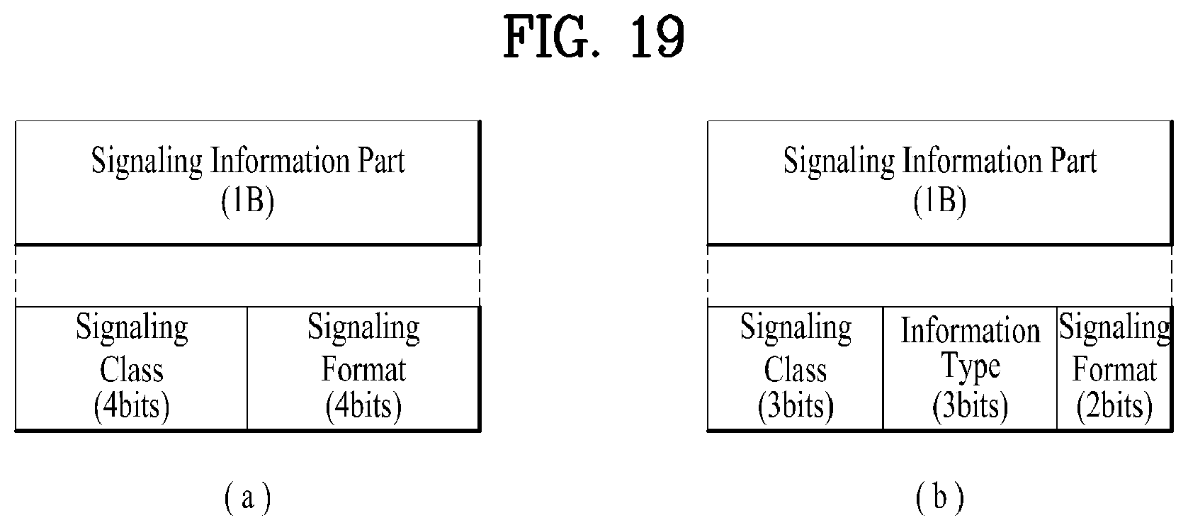
D00020

D00021

D00022

D00023

D00024

D00025

D00026

D00027
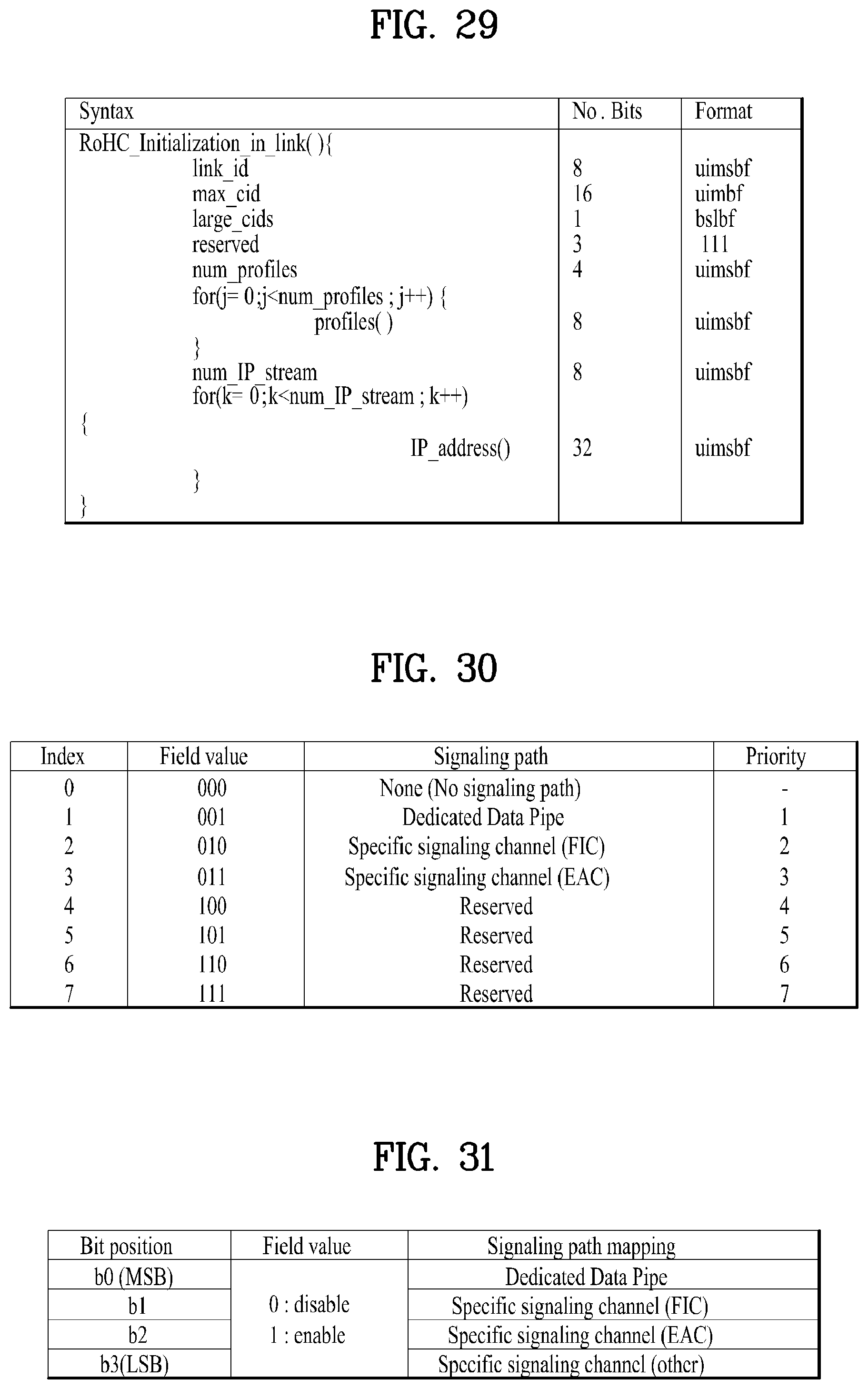
D00028

D00029

D00030

D00031

D00032

D00033

D00034

XML
uspto.report is an independent third-party trademark research tool that is not affiliated, endorsed, or sponsored by the United States Patent and Trademark Office (USPTO) or any other governmental organization. The information provided by uspto.report is based on publicly available data at the time of writing and is intended for informational purposes only.
While we strive to provide accurate and up-to-date information, we do not guarantee the accuracy, completeness, reliability, or suitability of the information displayed on this site. The use of this site is at your own risk. Any reliance you place on such information is therefore strictly at your own risk.
All official trademark data, including owner information, should be verified by visiting the official USPTO website at www.uspto.gov. This site is not intended to replace professional legal advice and should not be used as a substitute for consulting with a legal professional who is knowledgeable about trademark law.