Rotatable input mechanism having adjustable output
Jackson , et al.
U.S. patent number 10,579,090 [Application Number 15/870,718] was granted by the patent office on 2020-03-03 for rotatable input mechanism having adjustable output. This patent grant is currently assigned to APPLE INC.. The grantee listed for this patent is Apple Inc.. Invention is credited to Brenton A. Baugh, Benjamin G. Jackson, Megan A. McClain, Steven J. Taylor.


View All Diagrams
| United States Patent | 10,579,090 |
| Jackson , et al. | March 3, 2020 |
| **Please see images for: ( Certificate of Correction ) ** |
Rotatable input mechanism having adjustable output
Abstract
Disclosed herein is an input device that replicates mechanical actuation of a rotatable input mechanism in such a way that the haptic output provided by the input device is controllable.
| Inventors: | Jackson; Benjamin G. (Cupertino, CA), Baugh; Brenton A. (Los Altos Hills, CA), McClain; Megan A. (San Francisco, CA), Taylor; Steven J. (San Jose, CA) | ||||||||||
|---|---|---|---|---|---|---|---|---|---|---|---|
| Applicant: |
|
||||||||||
| Assignee: | APPLE INC. (Cupertino,
CA) |
||||||||||
| Family ID: | 59680118 | ||||||||||
| Appl. No.: | 15/870,718 | ||||||||||
| Filed: | January 12, 2018 |
Prior Publication Data
| Document Identifier | Publication Date | |
|---|---|---|
| US 20180136686 A1 | May 17, 2018 | |
Related U.S. Patent Documents
| Application Number | Filing Date | Patent Number | Issue Date | ||
|---|---|---|---|---|---|
| 15055554 | Feb 27, 2016 | 9891651 | |||
| Current U.S. Class: | 1/1 |
| Current CPC Class: | G05G 5/03 (20130101); G06F 3/016 (20130101); G05G 1/08 (20130101) |
| Current International Class: | G05G 5/03 (20080401); G06F 3/01 (20060101); G05G 1/08 (20060101) |
References Cited [Referenced By]
U.S. Patent Documents
| 2237860 | April 1941 | Bolle |
| 2288215 | June 1942 | Taubert et al. |
| 2497935 | February 1950 | Feurer |
| 2771734 | November 1956 | Morf |
| 2788236 | April 1957 | Kafowi |
| 2797592 | July 1957 | Marrapese |
| 3040514 | June 1962 | Dinstman |
| 3056030 | September 1962 | Kelchner |
| 3130539 | April 1964 | Davis |
| 3355873 | December 1967 | Morf |
| 3362154 | January 1968 | Perret |
| 3410247 | November 1968 | Dronberger |
| 3495398 | February 1970 | Widmer et al. |
| 3577876 | May 1971 | Spadini |
| 3621649 | November 1971 | Vulcan et al. |
| 3662618 | May 1972 | Kroll et al. |
| 3733803 | May 1973 | Hiraga |
| 4007347 | February 1977 | Haber |
| 4031341 | June 1977 | Wuthrich et al. |
| 4037068 | July 1977 | Gaynor |
| 4077200 | March 1978 | Schneider |
| 4133404 | January 1979 | Griffin |
| 4170104 | October 1979 | Yamagata |
| 4258096 | March 1981 | LaMarche |
| 4287400 | September 1981 | Kitik |
| 4289400 | September 1981 | Kubola et al. |
| 4311026 | January 1982 | Ochoa |
| 4311990 | January 1982 | Burke |
| 4324956 | April 1982 | Sakakino et al. |
| 4345119 | August 1982 | Latasiewicz |
| 4364674 | December 1982 | Tesch |
| 4379642 | April 1983 | Meyrat |
| 4395134 | July 1983 | Luce |
| 4396298 | August 1983 | Ripley |
| 4417824 | November 1983 | Paterson et al. |
| 4520306 | May 1985 | Kirby |
| 4581509 | April 1986 | Sanford et al. |
| 4600316 | July 1986 | Besson |
| 4617461 | October 1986 | Subbarao et al. |
| 4634861 | January 1987 | Ching et al. |
| 4641026 | February 1987 | Garcia, Jr. |
| 4670737 | June 1987 | Rilling |
| 4766642 | August 1988 | Gaffney et al. |
| 4783772 | November 1988 | Umemoto et al. |
| 4884073 | November 1989 | Souloumiac |
| 4914831 | April 1990 | Kanezashi et al. |
| 4922070 | May 1990 | Dorkinski |
| 4931794 | June 1990 | Haag |
| 4952799 | August 1990 | Loewen |
| 4980685 | December 1990 | Souloumiac et al. |
| 4987299 | January 1991 | Kobayashi et al. |
| 5034602 | July 1991 | Garcia et al. |
| 5214278 | May 1993 | Banda |
| 5258592 | November 1993 | Nishikawa et al. |
| 5288993 | February 1994 | Bidiville et al. |
| 5347123 | September 1994 | Jackson et al. |
| 5383166 | January 1995 | Gallay |
| 5471054 | November 1995 | Watanabe |
| 5509174 | April 1996 | Worrell |
| 5572314 | November 1996 | Hyman et al. |
| 5583560 | December 1996 | Florin et al. |
| 5631881 | May 1997 | Pessey et al. |
| 5726645 | March 1998 | Kamon et al. |
| 5748111 | May 1998 | Bates |
| 5825353 | October 1998 | Will |
| 5841050 | November 1998 | Clift et al. |
| 5847335 | December 1998 | Sugahara et al. |
| 5867082 | February 1999 | Van Zeeland |
| 5943233 | August 1999 | Ebina |
| 5953001 | September 1999 | Challener et al. |
| 5960366 | September 1999 | Duwaer et al. |
| 5963332 | October 1999 | Feldman et al. |
| 5999168 | December 1999 | Rosenberg |
| 6069567 | May 2000 | Zawilski |
| 6134189 | October 2000 | Carrard |
| 6154201 | November 2000 | Levin et al. |
| 6175679 | January 2001 | Veligdan et al. |
| 6241684 | June 2001 | Amano |
| 6246050 | June 2001 | Tullis et al. |
| 6252825 | June 2001 | Perotto |
| 6304247 | October 2001 | Black |
| 6355891 | March 2002 | Ikunami |
| 6361502 | March 2002 | Puolakanaho et al. |
| 6377239 | April 2002 | Isikawa |
| 6392640 | May 2002 | Will |
| 6396006 | May 2002 | Yokoji et al. |
| 6422740 | July 2002 | Leuenberger |
| 6477117 | November 2002 | Narayanaswami et al. |
| 6502982 | January 2003 | Bach et al. |
| 6525278 | February 2003 | Villain et al. |
| 6556222 | April 2003 | Narayanaswami |
| 6575618 | June 2003 | Inoue et al. |
| 6587400 | July 2003 | Line |
| 6646635 | November 2003 | Pogatetz et al. |
| 6661438 | November 2003 | Shiraishi et al. |
| 6672758 | January 2004 | Ehrsam et al. |
| 6794992 | September 2004 | Rogers |
| 6809275 | October 2004 | Cheng et al. |
| 6834430 | December 2004 | Worrell |
| 6846998 | January 2005 | Hasumi et al. |
| 6882596 | April 2005 | Guanter |
| 6888076 | May 2005 | Hetherington |
| 6896403 | May 2005 | Gau |
| 6909378 | June 2005 | Lambrechts et al. |
| 6914551 | July 2005 | Vidal |
| 6961099 | November 2005 | Takano et al. |
| 6963039 | November 2005 | Weng et al. |
| 6967903 | November 2005 | Guanter |
| 6977868 | December 2005 | Brewer et al. |
| 6982930 | January 2006 | Hung |
| 6985107 | January 2006 | Anson |
| 6987568 | January 2006 | Dana |
| 6998553 | February 2006 | Hisamune et al. |
| 7016263 | March 2006 | Gueissaz et al. |
| 7034237 | April 2006 | Ferri et al. |
| 7081905 | July 2006 | Raghunath et al. |
| 7102626 | September 2006 | Denny, III |
| 7111365 | September 2006 | Howie, Jr. |
| 7113450 | September 2006 | Plancon |
| 7119289 | October 2006 | Lacroix |
| 7135673 | November 2006 | Saint Clair |
| 7167083 | January 2007 | Giles |
| 7244927 | July 2007 | Huynh |
| 7255473 | August 2007 | Hiranuma et al. |
| 7265336 | September 2007 | Hataguchi et al. |
| 7274303 | September 2007 | Dresti et al. |
| 7285738 | October 2007 | Lavigne et al. |
| 7286063 | October 2007 | Gauthey |
| 7292741 | November 2007 | Ishiyama et al. |
| 7358481 | April 2008 | Yeoh et al. |
| 7369308 | May 2008 | Tsuruta et al. |
| 7371745 | May 2008 | Ebright et al. |
| 7385874 | June 2008 | Vuilleumier |
| 7404667 | July 2008 | Born et al. |
| 7465917 | December 2008 | Chin et al. |
| 7468036 | December 2008 | Rulkov et al. |
| 7506269 | March 2009 | Lang et al. |
| 7520664 | April 2009 | Wai |
| 7528824 | May 2009 | Kong |
| 7545367 | June 2009 | Sunda et al. |
| 7591582 | September 2009 | Hiranuma et al. |
| 7593755 | September 2009 | Colando et al. |
| 7605846 | October 2009 | Watanabe |
| 7634263 | December 2009 | Louch et al. |
| 7646677 | January 2010 | Nakamura |
| 7655874 | February 2010 | Akieda |
| 7682070 | March 2010 | Burton |
| 7708457 | May 2010 | Girardin |
| 7710456 | May 2010 | Koshiba et al. |
| 7732724 | June 2010 | Otani et al. |
| 7761246 | July 2010 | Matsui |
| 7763819 | July 2010 | Ieda et al. |
| 7772507 | August 2010 | Orr |
| 7778115 | August 2010 | Ruchonnet |
| 7781726 | August 2010 | Matsui et al. |
| RE41637 | September 2010 | O'Hara et al. |
| 7791597 | September 2010 | Silverstein et al. |
| 7822469 | October 2010 | Lo |
| 7856255 | December 2010 | Tsuchiya et al. |
| 7858583 | December 2010 | Schmidt et al. |
| 7865324 | January 2011 | Lindberg |
| 7946758 | May 2011 | Mooring |
| 8063892 | November 2011 | Shahoian et al. |
| 8138488 | March 2012 | Grot |
| 8143981 | March 2012 | Washizu et al. |
| 8167126 | May 2012 | Stiehl |
| 8169402 | May 2012 | Shahoian et al. |
| 8188989 | May 2012 | Levin et al. |
| 8195313 | June 2012 | Fadell et al. |
| 8229535 | July 2012 | Mensinger et al. |
| 8248815 | August 2012 | Yang et al. |
| 8263886 | September 2012 | Lin et al. |
| 8263889 | September 2012 | Takahashi et al. |
| 8294670 | October 2012 | Griffin et al. |
| 8312495 | November 2012 | Vanderhoff |
| 8368677 | February 2013 | Yamamoto |
| 8371745 | February 2013 | Manni |
| 8373661 | February 2013 | Lan et al. |
| 8410971 | April 2013 | Friedlander |
| 8432368 | April 2013 | Momeyer et al. |
| 8439559 | May 2013 | Luk et al. |
| 8441450 | May 2013 | Degner et al. |
| 8446713 | May 2013 | Lai |
| 8456430 | June 2013 | Oliver et al. |
| 8477118 | July 2013 | Lan et al. |
| 8493190 | July 2013 | Periquet et al. |
| 8508511 | August 2013 | Tanaka et al. |
| 8525777 | September 2013 | Stavely et al. |
| 8562489 | October 2013 | Burton et al. |
| 8568313 | October 2013 | Sadhu |
| 8576044 | November 2013 | Chapman |
| 8593598 | November 2013 | Chen et al. |
| 8607662 | December 2013 | Huang |
| 8614881 | December 2013 | Yoo |
| 8783944 | February 2014 | Doi |
| 8666682 | March 2014 | LaVigne et al. |
| 8677285 | March 2014 | Tsern et al. |
| 8704787 | April 2014 | Yamamoto |
| 8711093 | April 2014 | Ong et al. |
| 8724087 | May 2014 | Van De Kerkhof et al. |
| 8730167 | May 2014 | Ming et al. |
| 8743088 | June 2014 | Watanabe |
| 8804993 | August 2014 | Shukla et al. |
| 8816962 | August 2014 | Obermeyer et al. |
| 8824245 | September 2014 | Lau et al. |
| 8847741 | September 2014 | Birnbaum et al. |
| 8859971 | October 2014 | Weber |
| 8860674 | October 2014 | Lee et al. |
| 8863219 | October 2014 | Brown et al. |
| D717679 | November 2014 | Anderssen |
| 8878657 | November 2014 | Periquet et al. |
| 8885856 | November 2014 | Sacha |
| 8895911 | November 2014 | Takahashi |
| 8905631 | December 2014 | Sakurazawa et al. |
| 8908477 | December 2014 | Peters |
| 8920022 | December 2014 | Ishida et al. |
| 8922399 | December 2014 | Bajaj et al. |
| 8928452 | January 2015 | Kim et al. |
| 8954135 | February 2015 | Yuen et al. |
| 8975543 | March 2015 | Hakemeyer |
| 8994827 | March 2015 | Mistry et al. |
| 9001625 | April 2015 | Essery et al. |
| 9024733 | May 2015 | Wouters |
| 9028134 | May 2015 | Koshoji et al. |
| 9030446 | May 2015 | Mistry et al. |
| 9034666 | May 2015 | Vaganov et al. |
| 9039614 | May 2015 | Yuen et al. |
| 9041663 | May 2015 | Westerman |
| 9042971 | May 2015 | Brumback et al. |
| 9052696 | June 2015 | Breuillot et al. |
| 9086717 | July 2015 | Meerovitsch |
| 9086738 | July 2015 | Leung et al. |
| 9101184 | August 2015 | Wilson |
| 9105413 | August 2015 | Hiranuma et al. |
| 9123483 | September 2015 | Ferri et al. |
| 9141087 | September 2015 | Brown et al. |
| 9176577 | November 2015 | Jangaard et al. |
| 9176598 | November 2015 | Sweetser et al. |
| 9202372 | December 2015 | Reams et al. |
| 9213409 | December 2015 | Redelsheimer et al. |
| 9223296 | December 2015 | Yang et al. |
| 9241635 | January 2016 | Yuen et al. |
| 9244438 | January 2016 | Hoover et al. |
| 9256209 | February 2016 | Yang et al. |
| 9277156 | March 2016 | Bennett et al. |
| 9350850 | May 2016 | Pope et al. |
| 9386932 | July 2016 | Chatterjee et al. |
| 9426275 | August 2016 | Eim et al. |
| 9430042 | August 2016 | Levin |
| 9437357 | September 2016 | Furuki et al. |
| 9449770 | September 2016 | Sanford et al. |
| 9501044 | November 2016 | Jackson et al. |
| 9520100 | December 2016 | Houjou et al. |
| 9532723 | January 2017 | Kim |
| 9542016 | January 2017 | Armstrong-Muntner |
| 9545541 | January 2017 | Aragones et al. |
| 9552023 | January 2017 | Joo et al. |
| 9599964 | March 2017 | Gracia |
| 9607505 | March 2017 | Rothkopf et al. |
| 9620312 | April 2017 | Ely et al. |
| 9627163 | April 2017 | Ely |
| 9632318 | April 2017 | Goto et al. |
| 9638587 | May 2017 | Marques et al. |
| 9659482 | May 2017 | Yang et al. |
| 9680831 | June 2017 | Jooste et al. |
| 9709956 | July 2017 | Ely et al. |
| 9753436 | September 2017 | Ely et al. |
| D800172 | October 2017 | Akana |
| 9800717 | October 2017 | Ma et al. |
| 9836025 | December 2017 | Ely et al. |
| 9939923 | April 2018 | Sharma |
| 9946297 | April 2018 | Nazzaro et al. |
| 9971305 | May 2018 | Ely et al. |
| 9971405 | May 2018 | Holenarsipur et al. |
| 9979426 | May 2018 | Na et al. |
| 10001817 | June 2018 | Zambetti et al. |
| 10092203 | October 2018 | Mirov |
| 10114342 | October 2018 | Kim et al. |
| 10209148 | February 2019 | Lyon et al. |
| 10331082 | June 2019 | Ely et al. |
| 2003/0174590 | September 2003 | Arikawa et al. |
| 2004/0047244 | March 2004 | Iino et al. |
| 2004/0082414 | April 2004 | Knox |
| 2004/0130971 | July 2004 | Ecoffet et al. |
| 2004/0264301 | December 2004 | Howard et al. |
| 2005/0075558 | April 2005 | Vecerina et al. |
| 2005/0088417 | April 2005 | Mulligan |
| 2005/0134561 | June 2005 | Tierling |
| 2005/0205377 | September 2005 | Borgerson |
| 2006/0250377 | November 2006 | Zadesky et al. |
| 2007/0013775 | January 2007 | Shin |
| 2007/0050054 | March 2007 | Sambandam Guruparan et al. |
| 2007/0211042 | September 2007 | Kim et al. |
| 2007/0222756 | September 2007 | Wu et al. |
| 2007/0229671 | October 2007 | Takeshita et al. |
| 2007/0247421 | October 2007 | Orsley et al. |
| 2008/0130914 | June 2008 | Cho |
| 2009/0051649 | February 2009 | Rondel |
| 2009/0073119 | March 2009 | Le et al. |
| 2009/0122656 | May 2009 | Bonnet et al. |
| 2009/0146975 | June 2009 | Chang |
| 2009/0152452 | June 2009 | Lee et al. |
| 2009/0188226 | July 2009 | Carlson |
| 2009/0217207 | August 2009 | Kagermeier et al. |
| 2009/0285443 | November 2009 | Camp et al. |
| 2009/0312051 | December 2009 | Hansson et al. |
| 2010/0033430 | February 2010 | Kakutani et al. |
| 2010/0053468 | March 2010 | Havrill |
| 2010/0081375 | April 2010 | Rosenblatt et al. |
| 2010/0149099 | June 2010 | Elias |
| 2011/0007468 | January 2011 | Burton et al. |
| 2011/0090148 | April 2011 | Li et al. |
| 2011/0158057 | June 2011 | Brewer et al. |
| 2011/0242064 | October 2011 | Ono et al. |
| 2011/0270358 | November 2011 | Davis |
| 2012/0067711 | March 2012 | Yang |
| 2012/0068857 | March 2012 | Rothkopf et al. |
| 2012/0075082 | March 2012 | Rothkopf et al. |
| 2012/0092383 | April 2012 | Hysek |
| 2012/0112859 | May 2012 | Park et al. |
| 2012/0113044 | May 2012 | Strazisar et al. |
| 2012/0206248 | August 2012 | Biggs |
| 2012/0272784 | November 2012 | Bailey et al. |
| 2013/0037396 | February 2013 | Yu |
| 2013/0087443 | April 2013 | Kikuchi |
| 2013/0191220 | July 2013 | Dent et al. |
| 2013/0235704 | September 2013 | Grinberg |
| 2013/0261405 | October 2013 | Lee et al. |
| 2013/0335196 | December 2013 | Zhang et al. |
| 2014/0071098 | March 2014 | You |
| 2014/0073486 | March 2014 | Ahmed et al. |
| 2014/0132516 | May 2014 | Tsai et al. |
| 2014/0197936 | July 2014 | Biggs et al. |
| 2014/0327630 | November 2014 | Burr et al. |
| 2014/0340318 | November 2014 | Stringer et al. |
| 2014/0347289 | November 2014 | Suh et al. |
| 2014/0368442 | December 2014 | Vahtola |
| 2014/0375579 | December 2014 | Fujiwara |
| 2015/0049059 | February 2015 | Zadesky |
| 2015/0098309 | April 2015 | Adams et al. |
| 2015/0124415 | May 2015 | Goyal et al. |
| 2015/0186609 | July 2015 | Utter, II |
| 2015/0221460 | August 2015 | Teplitxky et al. |
| 2015/0227217 | August 2015 | Fukumoto |
| 2015/0320346 | November 2015 | Chen |
| 2015/0338642 | November 2015 | Sanford |
| 2015/0366098 | December 2015 | Lapetina et al. |
| 2016/0018846 | January 2016 | Zenoff |
| 2016/0054813 | February 2016 | Shediwy et al. |
| 2016/0058375 | March 2016 | Rothkopf et al. |
| 2016/0061636 | March 2016 | Gowreesunker et al. |
| 2016/0062623 | March 2016 | Howard et al. |
| 2016/0069713 | March 2016 | Ruh et al. |
| 2016/0103985 | April 2016 | Shim et al. |
| 2016/0109861 | April 2016 | Kim et al. |
| 2016/0116306 | April 2016 | Ferri et al. |
| 2016/0147432 | May 2016 | Shi et al. |
| 2016/0168178 | June 2016 | Misra |
| 2016/0170598 | June 2016 | Zambetti et al. |
| 2016/0170608 | June 2016 | Zambetti et al. |
| 2016/0170624 | June 2016 | Zambetti et al. |
| 2016/0241688 | August 2016 | Vossoughi |
| 2016/0253487 | September 2016 | Sarkar et al. |
| 2016/0258784 | September 2016 | Boonsom et al. |
| 2016/0259301 | September 2016 | Ely |
| 2016/0306437 | October 2016 | Zhang et al. |
| 2016/0306446 | October 2016 | Chung et al. |
| 2016/0313703 | October 2016 | Ely et al. |
| 2016/0320583 | November 2016 | Hall, Jr. |
| 2016/0327911 | November 2016 | Eim et al. |
| 2016/0338642 | November 2016 | Parara et al. |
| 2016/0378069 | December 2016 | Rothkopf et al. |
| 2016/0378070 | December 2016 | Rothkopf et al. |
| 2016/0378071 | December 2016 | Rothkopf et al. |
| 2016/0378072 | December 2016 | Ely et al. |
| 2017/0003655 | January 2017 | Ely |
| 2017/0010751 | January 2017 | Shedletsky |
| 2017/0011210 | January 2017 | Cheong et al. |
| 2017/0027461 | February 2017 | Shin et al. |
| 2017/0031449 | February 2017 | Karsten et al. |
| 2017/0045958 | February 2017 | Battlogg et al. |
| 2017/0061863 | March 2017 | Eguchi |
| 2017/0069443 | March 2017 | Wang et al. |
| 2017/0069444 | March 2017 | Wang et al. |
| 2017/0069447 | March 2017 | Wang et al. |
| 2017/0090599 | March 2017 | Kuboyama |
| 2017/0104902 | April 2017 | Kim et al. |
| 2017/0139489 | May 2017 | Chen et al. |
| 2017/0216519 | August 2017 | Vouillamoz |
| 2017/0216668 | August 2017 | Burton et al. |
| 2017/0227980 | August 2017 | Hafez |
| 2017/0238138 | August 2017 | Aminzade |
| 2017/0248986 | August 2017 | Jackson et al. |
| 2017/0251561 | August 2017 | Fleck et al. |
| 2017/0269715 | September 2017 | Kim et al. |
| 2017/0285404 | October 2017 | Kubota et al. |
| 2017/0301314 | October 2017 | Kim et al. |
| 2017/0307414 | October 2017 | Ferri et al. |
| 2017/0331869 | November 2017 | Bendahan et al. |
| 2017/0357465 | December 2017 | Dzeryn et al. |
| 2018/0018026 | January 2018 | Bushnell et al. |
| 2018/0024683 | January 2018 | Ely et al. |
| 2018/0136613 | May 2018 | Ely et al. |
| 2018/0136686 | May 2018 | Jackson et al. |
| 2018/0196517 | July 2018 | Tan |
| 2018/0235491 | August 2018 | Bayley et al. |
| 2018/0239306 | August 2018 | Ely |
| 2018/0246469 | August 2018 | Ely et al. |
| 2018/0299834 | October 2018 | Ely et al. |
| 2018/0307363 | October 2018 | Ely et al. |
| 2018/0329368 | November 2018 | Ely et al. |
| 2018/0335891 | November 2018 | Shedletsky et al. |
| 2018/0341342 | November 2018 | Bushnell et al. |
| 2018/0364815 | December 2018 | Moussette et al. |
| 2019/0017846 | January 2019 | Boonsom et al. |
| 2019/0163324 | May 2019 | Shedletsky |
| 1888928 | Jan 1937 | CH | |||
| 1302740 | Sep 2001 | CN | |||
| 1445627 | Oct 2003 | CN | |||
| 1504843 | Jun 2004 | CN | |||
| 1624427 | Jun 2005 | CN | |||
| 1792295 | Jun 2006 | CN | |||
| 101201587 | Jun 2008 | CN | |||
| 201081979 | Jul 2008 | CN | |||
| 201262741 | Jun 2009 | CN | |||
| 101750958 | Jun 2010 | CN | |||
| 201638168 | Nov 2010 | CN | |||
| 101923314 | Dec 2010 | CN | |||
| 202008579 | Oct 2011 | CN | |||
| 102890443 | Jan 2013 | CN | |||
| 202710937 | Jan 2013 | CN | |||
| 103191557 | Jul 2013 | CN | |||
| 103253067 | Aug 2013 | CN | |||
| 103645804 | Mar 2014 | CN | |||
| 203564224 | Apr 2014 | CN | |||
| 103852090 | Jun 2014 | CN | |||
| 203630524 | Jun 2014 | CN | |||
| 103956006 | Jul 2014 | CN | |||
| 203693601 | Jul 2014 | CN | |||
| 203732900 | Jul 2014 | CN | |||
| 103995456 | Aug 2014 | CN | |||
| 203941395 | Nov 2014 | CN | |||
| 104777987 | Apr 2015 | CN | |||
| 104685794 | Jun 2015 | CN | |||
| 104880937 | Sep 2015 | CN | |||
| 204650147 | Sep 2015 | CN | |||
| 105096979 | Nov 2015 | CN | |||
| 105547146 | May 2016 | CN | |||
| 3706194 | Sep 1988 | DE | |||
| 102008023651 | Nov 2009 | DE | |||
| 102016215087 | Mar 2017 | DE | |||
| 0556155 | Aug 1993 | EP | |||
| 1345095 | Sep 2003 | EP | |||
| 1669724 | Jun 2006 | EP | |||
| 1832969 | Sep 2007 | EP | |||
| 2375295 | Oct 2011 | EP | |||
| 2720129 | Apr 2014 | EP | |||
| 2884239 | Jun 2015 | EP | |||
| 2030093 | Oct 1970 | FR | |||
| 2801402 | May 2001 | FR | |||
| 2433211 | Jun 2007 | GB | |||
| S52151058 | Dec 1977 | JP | |||
| S54087779 | Jun 1979 | JP | |||
| S5708582 | Jan 1982 | JP | |||
| S5734457 | Feb 1982 | JP | |||
| H02285214 | Nov 1990 | JP | |||
| H04093719 | Mar 1992 | JP | |||
| H04157319 | May 1992 | JP | |||
| H05203465 | Aug 1993 | JP | |||
| H05312595 | Nov 1993 | JP | |||
| H06050927 | Dec 1994 | JP | |||
| H06331761 | Dec 1994 | JP | |||
| H06347293 | Dec 1994 | JP | |||
| H10161811 | Jun 1998 | JP | |||
| 11121210 | Apr 1999 | JP | |||
| H11191508 | Jul 1999 | JP | |||
| 2000337892 | Dec 2000 | JP | |||
| 2001084934 | Mar 2001 | JP | |||
| 2001167651 | Jun 2001 | JP | |||
| 2001202178 | Jul 2001 | JP | |||
| 2003050668 | Feb 2003 | JP | |||
| 2003151410 | May 2003 | JP | |||
| 2003331693 | Nov 2003 | JP | |||
| 2004184396 | Jul 2004 | JP | |||
| 2005017011 | Jan 2005 | JP | |||
| 2005063200 | Mar 2005 | JP | |||
| 2005108630 | Apr 2005 | JP | |||
| 2006164275 | Jun 2006 | JP | |||
| 2007149620 | Jun 2007 | JP | |||
| 2007248176 | Sep 2007 | JP | |||
| 2007311153 | Nov 2007 | JP | |||
| 2008053980 | Mar 2008 | JP | |||
| 2008122124 | May 2008 | JP | |||
| 2008122377 | May 2008 | JP | |||
| 2008170436 | Jul 2008 | JP | |||
| 2008235226 | Oct 2008 | JP | |||
| 2009070657 | Apr 2009 | JP | |||
| 2010032545 | Feb 2010 | JP | |||
| 2010165001 | Jul 2010 | JP | |||
| 2010186572 | Aug 2010 | JP | |||
| 2010243344 | Oct 2010 | JP | |||
| 2010244797 | Oct 2010 | JP | |||
| 2011165468 | Aug 2011 | JP | |||
| 2013057516 | Mar 2013 | JP | |||
| 2013079961 | May 2013 | JP | |||
| 2014174031 | Sep 2014 | JP | |||
| 20010030477 | Apr 2001 | KR | |||
| 20070014247 | Feb 2007 | KR | |||
| 100754674 | Sep 2007 | KR | |||
| 20080045397 | May 2008 | KR | |||
| 2020100007563 | Jul 2010 | KR | |||
| 20110011393 | Feb 2011 | KR | |||
| 20110012784 | Feb 2011 | KR | |||
| 20110113368 | Oct 2011 | KR | |||
| 1040225 | Nov 2014 | NL | |||
| 0129033 | Nov 2013 | RO | |||
| 200633681 | Oct 2006 | TW | |||
| WO2001/022038 | Mar 2001 | WO | |||
| WO2001/069567 | Sep 2001 | WO | |||
| WO2010/058376 | May 2010 | WO | |||
| WO2012/083380 | Jun 2012 | WO | |||
| WO2012/094805 | Jul 2012 | WO | |||
| WO2014/018118 | Jan 2014 | WO | |||
| WO-2014200766 | Dec 2014 | WO | |||
| WO2015/147756 | Oct 2015 | WO | |||
| WO2016/104922 | Jun 2016 | WO | |||
| WO2016/155761 | Oct 2016 | WO | |||
| WO2017/013278 | Jan 2017 | WO | |||
Other References
|
Author Unknown, "Desirable Android Wear smartwatch from LG," Gulf News, Dubai, 3 pages, Jan. 30, 2015. cited by applicant . Author Unknown, "Fossil Q ups smartwatch game with handsome design and build," Business Mirror, Makati City, Philippines, 3 pages, Dec. 20, 2016. cited by applicant . Author Unknown, "MyKronoz ZeTime: World's Most Funded Hybrid Smartwatch Raised over $3M on Kickstarter, Running until Apr. 27," Business Wire, New York, New York, 3 pages, Apr. 21, 2017. cited by applicant . Author Unknown, "How Vesag Helps Kids Women and Visitors," http://www.sooperarticles.com/health-fitness-articles/children-health-art- icles/how-vesag-helps-kids-women-visitors-218542.html, 2 pages, at least as early as May 20, 2015. cited by applicant . Author Unknown, "m Health," http://mhealth.vesag.com/?m=201012, 7 pages, Dec. 23, 2010. cited by applicant . Author Unknown, "mHealth Summit 2010," http://www.virtualpressoffice.com/eventsSubmenu.do?page=exhibitorPage&sho- wld=1551&companyId=5394, 5 pages, Nov. 18, 2010. cited by applicant . Author Unknown, "RedEye mini Plug-in Universal Remote Adapter for iPhone, iPod touch and iPad," Amazon.com, 4 pages, date unknown. cited by applicant . Author Unknown, "Re iPhone Universal Remote Control--Infrared Remote Control Accessory for iPhone and iPod touch," http://www.amazon.com/iPhone-Universal-Remote-Control-Accessory/dp/tech-d- ata/B0038Z4 . . . , 2 pages, at least as early as Jul. 15, 2010. cited by applicant . Author Unknown, "Vesag Wrist Watch for Dementia Care from VYZIN," http://vyasa-kaaranam-ketkadey.blogspot.com/2011/03/vesag-wrist-watch-for- -dementia-care.html, 2 pages, Mar. 31, 2011. cited by applicant . Author Unknown, "Vyzin Electronics Private Limited launches Vesag Watch," http://www.virtualpressoffice.com/showJointPage.do?page=jp&showId=1544, 5 pages, Jan. 6, 2011. cited by applicant . Author Unknown, "Vyzin Unveiled Personal Emergency Response System (PERS) with Remote Health Monitoring That Can Be Used for Entire Family," http://www.24-7pressrelease.com/press-release/vyzin-unveiled-personal-eme- rgency-response-system-pers-with-remote-health-monitoring-that-can-be-used- -for-entire-family-219317.php, 2 pages, Jun. 17, 2011. cited by applicant . Author Unknown, "DeskThorityNet, Optical Switch Keyboards," http://deskthority.net/keyboards-f2/optical-switch-keyboards-t1474.html, 22 pages, Jul. 11, 2015. cited by applicant . Epstein et al., "Economical, High-Performance Optical Encoders," Hewlett-Packard Journal, pp. 99-106, Oct. 1988. [text only version]. cited by applicant . GreyB, "Google Watch: Convert your arm into a keyboard," http://www.whatafuture.com/2014/02/28/google-smartwatch/#sthash.Yk35cDXK.- dpbs, 3 pages, Feb. 28, 2014. cited by applicant . IBM, "Additional Functionality Added to Cell Phone via "Learning" Function Button," www.ip.com, 2 pages, Feb. 21, 2007. cited by applicant . Kim, Joseph, "2010 mHealth Summit Emerges as Major One-Stop U.S. Venue for Mobile Health," http://www.medicineandtechnology.com/2010/08/2010-mhealth-summit-emerges-- as-major.html, 3 pages, Aug. 26, 2010. cited by applicant . Krishnan et al., "A Miniature Surface Mount Reflective Optical Shaft Encoder," Hewlett-Packard Journal, Article 8, pp. 1-6, Dec. 1996. cited by applicant . Rick, "How VESAG Helps Health Conscious Citizens," http://sensetekgroup.com/2010/11/29/wireless-health-monitoring-system/, 2 pages, Nov. 29, 2010. cited by applicant . Sadhu, Rajendra, "How VESAG Helps People Who Want to `Be There`?," http://ezinearticles.com/?How-Vesag-Helps-People-Who-Want-to-Be-There?&id- -5423873, 1 page, Nov. 22, 2010. cited by applicant . Sadhu, Rajendra, "Mobile Innovation Helps Dementia and Alzheimer's Patients," http://www.itnewsafrica.com/2010/11/mobile-innovation-helps-dementia-anda- lzheimer%E2%80%99s-patients/, 3 pages, Nov. 22, 2010. cited by applicant . Sherr, Sol, "Input Devices," p. 55, Mar. 1988. cited by applicant . Tran et al., "Universal Programmable Remote Control/Telephone," www.ip.com, 2 pages, May 1, 1992. cited by applicant. |
Primary Examiner: Foxx; Chico A
Attorney, Agent or Firm: Brownstein Hyatt Farber Schreck, LLP
Parent Case Text
CROSS-REFERENCE TO RELATED APPLICATION(S)
This application is a continuation patent application of U.S. patent application Ser. No. 15/055,554, filed Feb. 27, 2016 and titled "Rotatable Input Mechanism Having Adjustable Output," the disclosure of which is hereby incorporated herein by reference in its entirety.
Claims
What is claimed is:
1. A watch comprising: a housing; a display positioned at least partially within the housing and configured to display a user interface; a touch sensor positioned over the display and configured to receive a user input; a rotatable crown positioned along a side of the housing; and an actuation mechanism configured to produce haptic outputs by repeatedly varying an amount of friction between the actuation mechanism and the rotatable crown during a rotation of the rotatable crown, wherein: in a first mode, the actuation mechanism produces a first haptic output during the rotation of the rotatable crown, the first haptic output corresponding to a first sequence of tactilely perceptible changes in resistance to a first turning force; and in a second mode, the actuation mechanism produces a second haptic output that is different from the first haptic output during the rotation of the rotatable crown, the second haptic output corresponding to a second sequence of tactilely perceptible changes in resistance to a second turning force.
2. The watch of claim 1, wherein: the user interface comprises a displayed element; and the displayed element is modified in response to the rotation of the rotatable crown.
3. The watch of claim 2, wherein: the displayed element comprises at least one of an icon, a menu item, or a display screen; and modifying the displayed element comprises at least one of selecting the displayed element, zooming in, zooming out, or navigating between the displayed element and an additional displayed element.
4. The watch of claim 1, wherein: the user interface displays a scrollable list having a set of selectable elements; in the first mode, a first selectable element of the set of selectable elements that is not a last item of the scrollable list is selected; in the second mode, a second selectable element of the set of selectable elements that is the last item of the scrollable list is selected; and the actuation mechanism produces the second haptic output in response to the rotatable crown being rotated while the last item of the scrollable list is selected.
5. The watch of claim 4, wherein: the rotation causes a different selectable element of the set of selectable elements to be selected; the first haptic output indicates that the different selectable element has been selected; and if the different selectable element is the second selectable element, the watch transitions to the second mode.
6. The watch of claim 1, wherein: in the first mode, a first torque is required to rotate the rotatable crown; and in the second mode, a second torque that is less than the first torque is required to rotate the rotatable crown.
7. The watch of claim 6, wherein: the user interface comprises a scrollable user interface; rotating the rotatable crown scrolls through the scrollable user interface; when in the first mode, in response to a speed of rotation of the rotatable crown exceeding a first threshold, the watch transitions to the second mode; and when in the second mode, in response to the speed of rotation of the rotatable crown being less than a second threshold, the watch transitions to the first mode.
8. The watch of claim 1, wherein the amount of friction repeatedly dynamically varies between a first non-zero amount and a second non-zero amount.
9. An electronic watch comprising: a housing; a rotatable crown coupled to the housing; and an actuation mechanism configured to produce haptic feedback by repeatedly changing an amount of friction between a first element and a second element during a rotation of the rotatable crown, wherein: in a first mode, the actuation mechanism produces a first number of haptic outputs per full rotation of the rotatable crown; and in a second mode, the actuation mechanism produces a second number of haptic outputs per full rotation of the rotatable crown, the second number of haptic outputs being different from the first number of haptic outputs.
10. The electronic watch of claim 9, wherein: a first haptic output of the first number of haptic outputs is provided every quarter rotation of the rotatable crown; and a second haptic output of the second number of haptic outputs is provided every half rotation of the rotatable crown.
11. The electronic watch of claim 9, wherein a strength of either of the first or the second number of haptic outputs varies over time.
12. The electronic watch of claim 9, wherein repeatedly changing the amount of friction between the first element and the second element repeatedly changes a torque required to rotate the rotatable crown.
13. The electronic watch of claim 9, wherein the actuation mechanism comprises a linear actuator.
14. The electronic watch of claim 13, wherein the linear actuator comprises a moveable mass and is configured to change a torque required to rotate the rotatable crown by moving the moveable mass such that the moveable mass contacts the rotatable crown.
15. The electronic watch of claim 14, wherein: the rotatable crown comprises a rotatable structure defining an inner sidewall; the linear actuator is disposed within the rotatable structure; and the moveable mass contacting the rotatable crown comprises the moveable mass contacting the inner sidewall of the rotatable structure.
16. The electronic watch of claim 9, wherein: the electronic watch further comprises a processing unit operably coupled to the actuation mechanism; and the actuation mechanism is configured to repeatedly change the amount of friction between the first element and the second element in response to receiving one or more signals from the processing unit, repeatedly changing the amount of friction comprising: causing the first element to exert a first force on the second element to cause a first amount of friction between the first element and the second element; and causing the first element to exert a second force different from the first force on the second element to cause a second amount of friction different than the first amount of friction between the first element and the second element.
17. A watch comprising: a housing; a processing unit positioned within the housing; a display disposed at least partially within the housing and configured to display multiple displayed elements; a rotatable crown coupled to the housing and configured to receive rotational inputs; and a haptic actuator configured to: produce a first haptic output by repeatedly changing an amount of friction between a first element and a second element in a first manner during a first rotation of the rotatable crown, the first haptic output corresponding to a first sequence of tactilely perceptible changes in resistance to a first turning force; and produce a second haptic output different from the first haptic output by repeatedly changing the amount of friction between the first element and the second element in a second manner during a second rotation of the rotatable crown, the second haptic output corresponding to a second sequence of tactilely perceptible changes in resistance to a second turning force, wherein: in response to receiving a first rotational input at the rotatable crown, the processing unit is configured to: modify a first displayed element of the multiple displayed elements; and cause the haptic actuator to provide the first haptic output; and in response to receiving a second rotational input, the watch is configured to: modify a second displayed element of the multiple displayed elements; and cause the haptic actuator to provide the second haptic output.
18. The watch of claim 17, wherein: the first rotational input comprises rotation of the rotatable crown in a first type of user interface; and the second rotational input comprises rotation of the rotatable crown in a second type of user interface.
19. The watch of claim 17, wherein at least one of changing the first displayed element or changing the second displayed element comprises navigating within a menu of a user interface of the watch.
20. The watch of claim 17, wherein: the first displayed element corresponds to a first application of the watch; and the second displayed element corresponds to a second application of the watch.
Description
FIELD
The described embodiments relate generally to a rotatable input mechanism having an adjustable haptic output. More specifically, the disclosed embodiments relate to an input device that simulates mechanical clicks or other types of haptic output provided by a knob, dial, or other such rotatable input mechanism.
BACKGROUND
Conventional rotary input mechanisms typically include a knob or dial and one or more mechanical detent features that interface with a component of the knob or dial. As the knob or dial rotates, the component of the knob or dial interacts with the mechanical detent features and provides an audible, a tactile, or a haptic feedback. However, the feedback provided by the mechanical detent features is limited by the spacing of the detents and/or how quickly the rotary input mechanism is turned.
Thus, in order to provide more granular output, the mechanical detent features are manufactured such that they are spaced closer together. Likewise, the mechanical detent features must be manufactured such that they are spaced farther apart from one another in order to provide less granular output. In either case, the detents are typically fixed during manufacturing and are invariant.
SUMMARY
Disclosed herein is a rotatable input mechanism that replicates mechanical clicks or other such haptic output provided by a mechanical ball and spring detent mechanism. However, unlike conventional mechanical ball and spring detent mechanisms (or similar mechanisms that provide a haptic output) the rotatable input mechanism described herein includes various components that enable the frequency, strength, and feel of the haptic output to be controllable and adjustable.
More specifically, disclosed herein is a rotatable input mechanism that includes a rotatable structure, a surface within the rotatable structure and a moveable mass. The rotatable input mechanism also includes an actuation mechanism that causes the moveable mass to engage and disengage from the surface, which dynamically changes a torque required to rotate the rotatable structure.
Also disclosed is a user-manipulable rotatable input mechanism. The user-manipulable rotatable input mechanism includes a rotatable structure configured to rotate about an axis and an actuation mechanism defining an engagement surface. In this embodiment, the engagement surface is configured to alternately contact and disengage from the rotatable structure, thereby varying friction between the engagement surface and the rotatable structure to provide a varying haptic output.
The present application also describes an input device having a cover, a feedback mechanism coupled to an inner surface of the cover, and a rotating center plate. The rotating center plate is operable to rotate both with the cover and independently of the cover. The rotating center plate also has one or more detents disposed on a perimeter surface. The detents interact with the feedback mechanism to provide a variable haptic output.
BRIEF DESCRIPTION OF THE DRAWINGS
The disclosure will be readily understood by the following detailed description in conjunction with the accompanying drawings, wherein like reference numerals designate like structural elements, and in which:
FIG. 1 illustrates an example rotatable input mechanism;
FIG. 2A illustrates a torque response profile showing an increase and decrease in tactile torque as the rotatable input mechanism is rotated according to a first example;
FIG. 2B illustrates a torque response profile showing an increase and decrease in tactile torque as the rotatable input mechanism is rotated according to a second example;
FIG. 2C illustrates a torque response profile showing an increase and decrease in tactile torque as the rotatable input mechanism is rotated according to a third example;
FIG. 2D illustrates a torque response profile showing an increase and decrease in tactile torque as the rotatable input mechanism is rotated according to a fourth example;
FIG. 3A illustrates an example user interface having a selector that may be moved by the rotatable input mechanism;
FIG. 3B illustrates the example user interface of FIG. 3A in which the selector has moved as a result of a rotation of the rotatable input mechanism;
FIG. 4A shows an example electronic device that may use or incorporate a rotatable input mechanism described herein;
FIG. 4B shows another example electronic device that may use or incorporate a rotatable input mechanism described herein;
FIG. 4C shows a third example electronic device that may use or incorporate a rotatable input mechanism described herein;
FIG. 4D shows a fourth example electronic device that may use or incorporate a rotatable input mechanism described herein;
FIG. 5A shows a cross-section view of a rotatable input mechanism in a first state according to a first embodiment;
FIG. 5B shows a cross-section view of the rotatable input mechanism of FIG. 5A in a second state;
FIG. 5C shows a cross-section view of the rotatable input mechanism of FIG. 5A in which a spring component of the rotatable input mechanism exhibits increased tension as a result of the rotatable input mechanism being rotated;
FIG. 6A shows a cross-section view of a rotatable input mechanism in a first state according to a second embodiment;
FIG. 6B shows a cross-section view of the rotatable input mechanism of FIG. 6A in a second state;
FIG. 6C shows a cross-section view of the rotatable input mechanism of FIG. 6A in which a spring component of the rotatable input mechanism exhibits increased tension as a result of the rotatable input mechanism being rotated;
FIG. 7A shows a cross-section view of a rotatable input mechanism in a first state according to a third embodiment;
FIG. 7B shows a cross-section view of the rotatable input mechanism of FIG. 7A in a second state;
FIG. 8A shows a cross-section view of a rotatable input mechanism in a first state according to a fourth embodiment;
FIG. 8B shows a cross-section view of the rotatable input mechanism of FIG. 8A in a second state;
FIG. 9A illustrates a top-down cross-section view of a rotatable input mechanism in a first state according to a fifth embodiment;
FIG. 9B shows a top-down cross-section view of the rotatable input mechanism of FIG. 9A in a second state;
FIG. 10A illustrates a top-down cross-section view of a rotatable input mechanism in a first state according to a sixth embodiment;
FIG. 10B shows a top-down cross-section view of the rotatable input mechanism of FIG. 10A in a second state;
FIG. 11A illustrates a top-down cross-section view of a rotatable input mechanism in a first state according to a seventh embodiment;
FIG. 11B shows a top-down cross-section view of the rotatable input mechanism of FIG. 11A in a second state;
FIG. 12A illustrates a top-down cross-section view of a rotatable input mechanism in a first state according to an eighth embodiment;
FIG. 12B shows a top-down cross-section view of the rotatable input mechanism of FIG. 12A in a second state; and
FIG. 13 illustrates example components of an electronic device that may use or incorporate the rotatable input mechanism described herein.
DETAILED DESCRIPTION
Reference will now be made in detail to representative embodiments illustrated in the accompanying drawings. It should be understood that the following descriptions are not intended to limit the embodiments to one preferred embodiment. To the contrary, it is intended to cover alternatives, modifications, and equivalents as can be included within the spirit and scope of the described embodiments as defined by the appended claims.
The following disclosure is directed to a rotatable input mechanism that replicates tactile or haptic output of a conventional rotatable input mechanism. However, unlike conventional rotatable input mechanisms, the haptic output of the rotatable input mechanism of the present disclosure is non-binary. More specifically, a frequency and/or a strength of haptic output provided by the rotatable input mechanism of the present disclosure may be controllable and adjustable. Because the haptic output is non-binary, a continuous range of haptic outputs may be provided to a user. Thus, the rotatable input mechanism may provide a first type of haptic output in a first situation, or in response to a first application, and provide a different type of haptic output in a second situation, or in conjunction with a second application.
"Frequency," as used herein, refers to a number of occurrences per unit of time. Assuming a constant rotational speed of the rotatable input mechanism, an output frequency may be adjusted by dynamically changing a number of detents, impacts simulating detents, friction events, and so on.
The rotatable input mechanism disclosed herein may be a user-manipulable rotatable input mechanism that may be used to navigate through or within a user interface. For example, the user interface may be provided on a display of an electronic device, a display of a computing device, or any other type of display that has selectable icons, features, menu items, applications, images, and the like. As a user manipulates the rotatable input mechanism, the different icons, features, menu items, applications, images, and the like may be highlighted or otherwise selected. In addition, as the user-manipulable rotatable input mechanism is rotated or is otherwise actuated, an audible and/or haptic output may be provided as each of the icons, features, menu items, applications, images, and the like is selected.
As will be explained below, output (whether audible, haptic, or other) may be provided in various ways. In some embodiments, an electromagnet associated with a clutch and spring component increases and/or decreases a torque required to rotate the rotatable input mechanism. The increase and/or decrease in torque simulates or replicates a negative torque and positive assistance torque of, for example, a ball and spring moving in and out of associated detents or notches in a mechanical ball and detent system.
In another embodiment, the rotatable input mechanism includes one or more actuation mechanisms incorporating one or more friction components. The one or more friction components alternate between contacting an inner surface of the rotatable input mechanism and not contacting (e.g., disengaging) the inner surface of the rotatable input mechanism. When the friction component contacts the inner surface of the rotatable input mechanism, the amount of friction is increased. As a result, the torque required to rotate the rotatable input mechanism also increases.
Likewise, when the friction component does not contact the inner surface of the rotatable input mechanism, the amount of friction is decreased. As a result, the torque required to rotate the rotatable input mechanism decreases. The increase and decrease in the friction and the resulting increase and decrease in the required torque may be used to simulate the haptic output of a conventional mechanical ball and spring detent mechanism.
Further, a force exerted on the inner surface by the friction component may be varied in order to vary the resulting friction and thus torque. This, in turn, varies the haptic and/or audible output, or may prevent them entirely.
In yet another embodiment, the rotatable input mechanism may utilize a rotating center plate and a ball and spring component or other such feedback mechanism to provide a programmable haptic output. For example, the rotating center plate may include one or more detents that interact with a ball and spring component or other such feedback mechanism to provide haptic output. The rotating center plate may rotate in a first direction or at a first speed while the ball and spring component may rotate in the first direction (or in a second direction) at a second speed. As each of the components rotate in different directions, the same direction, and/or at different speeds, a variable haptic output may be provided.
In each of the above examples, the increase and decrease in the amount of friction may be programmable. For example, the electromagnet, the actuators, or other components of the rotatable input mechanism may be fired or otherwise activated at various times in order to provide the variable haptic output. For example, a first type of haptic output may be provided by the rotatable input mechanism in response to a user navigating in a first type of user interface, a first type of menu within the first type of user interface, or using a certain application. Likewise, a second type of haptic output may be provided by the same rotatable input mechanism in response to a user navigating through a second user interface, a second menu in the first type of user interface, or using a second application.
Further, due to the programmable nature of the rotatable input mechanism, haptic output may be provided at various rotation points or at various frequencies. For example, the rotatable input mechanism may be programmed or otherwise receive instructions to provide haptic output every quarter of a turn of one revolution of the rotatable input mechanism in one situation, and provide haptic output every half of turn of a revolution of the rotatable input mechanism in a different situation.
These and other embodiments are discussed below with reference to FIGS. 1-13. However, those skilled in the art will readily appreciate that the detailed description given herein with respect to these Figures is for explanatory purposes only and should not be construed as limiting.
FIG. 1 illustrates an example rotatable input mechanism 100. The rotatable input mechanism 100 may be a user-manipulable rotatable input mechanism and may be configured to provide a haptic output and/or audible output when actuated by a user. For example, the rotatable input mechanism 100 may be associated with a user interface of an electronic device. As the user manipulates the rotatable input mechanism 100 to navigate within the user interface, the rotatable input mechanism 100 may provide a haptic and/or audible output as it rotates about its axis 110.
The rotatable input mechanism 100 may bidirectionally rotate about its axis 110 in the direction of arrows 120. Although arrows 120 illustrate that the rotatable input mechanism 100 may bidirectionally rotate about its axis 110, the rotatable input mechanism 100 may be configured to rotate in a single direction (e.g., in a clockwise direction or a counterclockwise direction).
As the rotatable input mechanism 100 rotates, various haptic outputs may be provided. More specifically, the rotatable input mechanism 100 may be configured to provide haptic and/or audible output after various angles or points of rotation. Further, these angles or points of rotation at which the haptic and/or audible output is provided may be dynamically adjustable such that the haptic output is non-binary. In addition, the amount of torque required to rotate the rotatable input mechanism 100 to or past the angles or points of rotation may also dynamically change, for example as friction between the rotatable mechanism and an actuator varies.
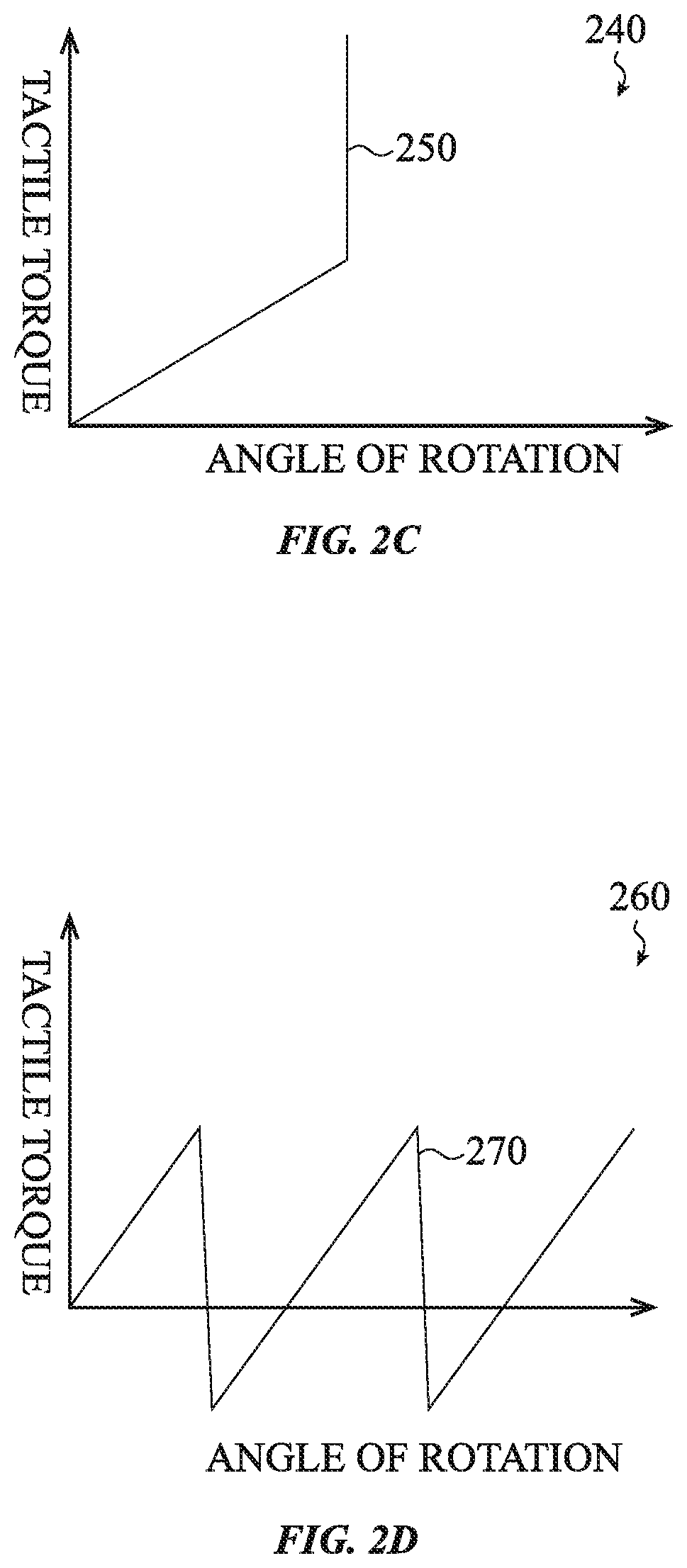
FIGS. 2A-2D illustrate various torque response profiles that may be utilized by a rotatable input mechanism such as, for example, rotatable input mechanism 100 of FIG. 1. Although the torque response profiles shown in FIGS. 2A-2D may not be to any particular scale, each of these figures illustrate torque response profiles that show an increase and decrease in the amount of tactile torque (e.g., input torque) required to rotate the rotatable input mechanism to, or past, various angles of rotation.
For example, FIG. 2A illustrates a first torque response profile 200. In this example, the profile is represented as a saw-tooth wave 210. In this particular implementation, the torque required to rotate the rotatable input mechanism increases as the angle of rotation of the rotatable input mechanism increases from a zero point. Once a certain angle of rotation has been reached, the amount of torque required to continue rotating the rotatable input mechanism decreases to substantially zero (or some other determined value). If the rotatable input mechanism continues to rotate, the amount of torque continues to increase and decrease in the manner explained above.
FIG. 2B illustrates a second torque response profile 220. In this example, the profile is represented as a square wave 230. In this particular implementation, the torque required to rotate the rotatable input mechanism increases dramatically at a first angle of rotation, stays constant for a continuous range of angles of rotation, and then decreases to zero or substantially zero (or some other determined value) once the desired angle of rotation has been reached.
FIG. 2C illustrates a third torque response profile 240. In this particular implementation, the torque required to rotate the rotatable input mechanism linearly increases until a maximum angle of rotation is reached. At that point, the rotatable input mechanism may not be rotated farther and so the force response profile 240 becomes a vertical line 250. This particular part of the torque response profile 240 indicates that the rotatable input mechanism has reached a maximum distance or angle of rotation. As one example, when the rotatable input mechanism is used to navigate within a user interface (such as will be described below) the torque response profile 240 may be used to indicate that an end (or a beginning) of a list has been reached.
FIG. 2D illustrates a fourth torque response profile 260. In this example, the profile is also represented as a saw-tooth wave 270. This example profile is similar to the profile described above with respect to FIG. 2A. For example, the torque required to rotate the rotatable input mechanism increases as the angle of rotation of the rotatable input mechanism increases from a zero point. However, once a certain angle of rotation has been reached, the amount of torque required to continue rotating the rotatable input mechanism decreases to substantially zero, some other determined value, or even a negative torque. The negative torque may cause the rotatable input mechanism to continue to rotate in the initial direction of rotation or may otherwise assist in the rotation of the rotatable input mechanism.
Although specific torque response profiles have been shown and described, various other torque response profiles may be utilized. For example, a profile for a torque response profile may be represented as a sine wave.
Each of the various profiles may be combined or otherwise concatenated with each other. Thus, a first torque response profile may be utilized within a first range of angles of rotation while a second torque response profile may be utilized within a second range of angles of rotation.
FIG. 3A illustrates an example user interface 300 of an electronic device. The user interface 300 has a selector 350 that may be manipulated by a rotatable input mechanism, such as, for example, the rotatable input mechanism 100 of FIG. 1. In this example, the user interface 300 has four different menu items, namely Item 1 310, Item 2 320, Item 3 330 and Item 4 340. As the rotatable input mechanism is manipulated or otherwise rotated to or past a given angle of rotation in a given direction (e.g., clockwise or counterclockwise), the selector 350 may move between the various items. Further, as the given angle of rotation is reached, the amount of force required to rotate the rotatable input mechanism may vary, for example as shown in any of the torque response profiles described above.
For example, when a user rotates the rotatable input mechanism to cause the selector 350 to move from Item 1 310 to Item 2 320, the amount of torque required to rotate the rotatable input mechanism may be represented by the torque response profile 200 (FIG. 2A). As the user continues to manipulate the rotatable input mechanism, selector 350 continues to move from Item 2 320 to Item 3 330 and the same torque response profile 200 may be used.
In some embodiments, various torque response profiles may be combined together as the rotatable input mechanism is actuated. For example and as shown in FIG. 3B, if the rotatable input mechanism has been rotated such that the selector 350 is on the last item, (Item 4 340), in the user interface 300, torque response profile 240 (FIG. 2C) may be used to indicate that further rotation in the clockwise direction is not available. However, rotation of the rotatable input mechanism in the counterclockwise direction (e.g., moving the selector 350 from Item 4 340 to Item 3 330) may be allowed. The counterclockwise rotation may utilize the torque response profile 200 of FIG. 2A.
In yet another implementation, as the selector 350 moves from Item 3 330 to Item 4 340, the torque response profile 200 (FIG. 2A) may be used. Continued rotation of the rotatable input mechanism may cause the selector 350 to move from Item 4 340 to Item 1 310. As such, torque response profile 220 (FIG. 2B) may be used to indicate that the selector 350 has wrapped around the user interface 300.
In some embodiments, a first direction of rotation and/or a first angle or range of angles of rotation may utilize a first torque response profile while a second direction of rotation and/or a first angle or range of angles of rotation may utilize a second torque response profile. For example, a clockwise rotation of the rotatable input mechanism may utilize torque response profile 200 (FIG. 2A) while a counterclockwise rotation of the rotatable input mechanism may utilize torque response profile 220 (FIG. 2B).
FIG. 4A illustrates an example electronic device 400 that uses or incorporates a rotatable input mechanism of the present disclosure. Although the electronic device 400 is shown as a wearable electronic device, the rotatable input mechanism described herein may be used with a variety of electronic devices, mechanical devices, electro-mechanical devices, computing devices, user interfaces, and so on. For example, the electronic device may be a mobile phone (FIG. 4B), a music or other such media player (FIG. 4C) or any other such electronic device.
The electronic device 400 illustrated in FIG. 4A may include a housing 405 and a display 410. The display 410 may be used to output or otherwise provide a user interface to a user. Once the user interface is provided on the display 410, a user-manipulable rotatable input mechanism (represented as rotatable input mechanism 415) may be used by a user to navigate within the user interface.
For example, a user may operate the rotatable input mechanism 415 to alter a user interface that is output on the display 410 of the electronic device 400. More specifically, a displayed element on the graphical user interface may be altered as the rotatable input mechanism 415 is manipulated by a user such as described above with respect to FIGS. 3A-3B. As such, the displayed element may be changed using different manipulations of the rotatable input mechanism 415. These manipulations may include pressing inward on the rotatable input mechanism 415, pulling outward on the rotatable input mechanism 415, rotating the rotatable input mechanism 415 in a first direction (e.g., to the right or clockwise), rotating the rotatable input mechanism 415 in a second direction (e.g., to the left or counterclockwise), and so on. More specifically, the rotatable input mechanism 415 may enable a cursor or other selector to select, zoom in and out, scroll, or otherwise navigate through various icons, menu items, display screens, and the like.
Although the rotatable input mechanism 415 is shown in FIG. 4A as extending from the housing 405 of the electronic device 400, this is not required. For example and as shown in FIG. 4B, an electronic device 420, such as, for example, a mobile phone, may have a rotatable input mechanism 435 that is flush or recessed with respect to a housing 425 and/or a display 430. More specifically, the rotatable input mechanism 435 may be flush or recessed with respect to a cover glass or other covering of the display 430 of the electronic device 420.
FIG. 4C illustrates another electronic device 440 that may use or otherwise incorporate the rotatable input mechanism disclosed herein. In this embodiment, the electronic device 440 is a portable media player. In this implementation, the electronic device 440 may have a rotatable input mechanism 455 that is flush or recessed with respect to the housing 445. As the rotatable input mechanism 455 is rotated, various icons, menu items, and the like that are output on a display 450 may be selected.
FIG. 4D illustrates another example device 460 that may use or incorporate the rotatable input mechanism described herein. In this particular embodiment, the rotatable input mechanism 470 may be configured as a rotatable ring that surrounds a display 465 of the electronic device 460.
Although specific devices have been shown and described, the rotatable input mechanism described herein may be used in a variety of devices. For example, the rotatable input mechanism described herein may be incorporated in any mechanical knob, dial or rotatable switch. Non-limiting examples include radio dials, speaker dials, and so on. Likewise, the rotatable input mechanism may be a rotating crown, a rotating bezel, and so on.
Regardless of the shape, position, or orientation of the rotatable input mechanism, as will be described below, when the rotatable input mechanism is rotated, various components of the rotatable input mechanism may provide an audible and/or a haptic output. "Haptic" as used herein, refers to a perceptible output that may be discerned by an individual that is contacting or otherwise using the rotatable input mechanism. The haptic output may be equivalent to the haptic output provided by a conventional ball and spring mechanical detent system. However, unlike conventional ball and spring mechanical detent systems in which the haptic output is static, the haptic output of the rotatable input mechanism is configurable and adjustable.
FIGS. 5A-12B show various embodiments of example rotatable input mechanisms that may be used with or incorporated into the various devices shown and described above. Further, each of the example rotatable input mechanisms may be user-manipulable rotatable input mechanisms. As such, a user may rotate or otherwise actuate the example rotatable input mechanisms to make a particular selection, change a setting of a device, navigate within or through a user interface and so on such as described herein.
More specifically, FIGS. 5A-8B illustrate various cross-section views of various rotatable input mechanisms, taken along line A-A of FIG. 4A, and FIGS. 9A-12B illustrate various top-down cross-section views of various rotatable input mechanisms according to various embodiments, and any of which may be used within the various devices described herein. Each of the embodiments described below may be used in or with various other mechanical, electro-mechanical and/or computing devices, user interfaces, and so on.
FIG. 5A shows a cross-section view of a rotatable input mechanism 500 in a first state according to a first embodiment. The rotatable input mechanism 500 may include a rotatable structure 510 positioned over and configured to rotate around a base portion 520. The rotatable structure 510 may have a rounded configuration and include one or more sidewalls that extend from a top surface. In other implementations, the rotatable structure 510 may be a ring that surrounds or partially surrounds the base portion. The rotatable structure 510 may also be a cover or a cap that at least partially overlays one or more surfaces of the base portion 520.
The rotatable structure 510 and/or the base portion 520 may be made from any suitable material including plastic, metal, aluminum, and so on. Although the rotatable structure 510 is shown as a single piece, the rotatable structure 510 may be made from multiple pieces or components.
The rotatable structure 510 may be configured to be manipulated by a user. As such, a user may rotate the rotatable structure 510 in a first direction and/or in a second direction. A shaft may be connected to base portion 520 and/or the rotatable structure 510. As such, the rotatable structure 510 may also be configured to be pressed inwardly and/or pulled outwardly.
As the rotatable structure 510 rotates, a user interface, such as for example, the user interface 300 (FIG. 3A), may be manipulated such as described above. The rotatable input mechanism 500 may also include one or more bearings 530 that are used to maintain spacing and positioning between the rotatable structure 510 and the base portion 520.
The rotatable input mechanism 500 may also include an actuation mechanism, such as, for example, an electromagnet 540. The electromagnet 540 may be flush with, be contained within, disposed on or otherwise coupled to or integrated with the base portion 520. The electromagnet 540 may interact with a moveable mass 550 that is coupled, via a spring component 560, to an inner surface of the rotatable structure 510. In some embodiments, the spring component 560 is a torsion spring. The spring component 560 holds the moveable mass 550 away from a friction surface 570 of the base portion 520. In some embodiments, the spring force of the spring component 560 is greater than the force of gravity on the moveable mass 550, which maintains the spacing between the friction surface 570 of the base portion 520 and the moveable mass 550.
In operation, the rotatable input mechanism 500 simulates haptic output of a mechanical spring ball and detent mechanism. For example, prior to or when the rotatable structure 510 is rotated, the electromagnet 540 is activated. In some examples, the electromagnet 540 may be activated or otherwise controlled by a voltage (e.g., analog voltage), a pulse width modulation scheme, or other such control mechanism.
Activation of the electromagnet 540 causes the moveable mass 550 to move from its nominal position (e.g., a position in which the moveable mass 550 is suspended from the spring component 560 such as shown in FIG. 5A) to a second position in which the moveable mass 550 is magnetically coupled to or otherwise engages with the base portion 520 such as shown in FIG. 5B. As the rotatable structure 510 rotates, the electromagnet 540 holds the moveable mass 550 in place or otherwise prevents the moveable mass 550 from rotating with the rotatable structure 510. In some embodiments and as briefly described above, the base portion 520 includes a friction surface 570 that increases friction between the moveable mass 550 and the base portion 520 which also helps prevent the moveable mass 550 from rotating as the rotatable structure 510 is rotated.
Because the spring component 560 is coupled to both the moveable mass 550 and the rotatable structure 510, as the rotatable structure 510 rotates and the moveable mass 550 remains stationary or substantially stationary, the spring component 560 experiences an increase in tension such as shown in FIG. 5C. As the tension in the spring component 560 increases, the user feels an increase in resistance, which replicates a negative resistance torque of a conventional ball and spring detent mechanism.
In some implementations, an increase in magnetic attraction between the moveable mass 550 and the base portion 520 can dynamically increase the friction between the two components. As such, the haptic output that is provided by the rotatable input mechanism 500 may dynamically change. Accordingly, the rotatable input mechanism 500 may provide non-binary haptic output. For example, a current increase through the electromagnet 540 increases a magnetic force between the moveable mass 550 and the base portion 520. This increases the friction and torque which affects the feel of the rotation of the rotatable structure 510.
Once a sufficient or desired torque requirement over a given amount of time or rotation distance of the rotatable structure 510 has been met or otherwise achieved, the electromagnet 540 may be deactivated. Once the electromagnet 540 has been deactivated, the moveable mass 550 disengages from the friction surface 570 and moves from the second position back to its nominal position.
Because the moveable mass 550 is now free to move and rotate, the tension in spring component 560 is released. As the tension in the spring component 560 is released, the moveable mass 550 rotates which simulates the positive assistance torque of a conventional ball and spring detent mechanism. More specifically, when the moveable mass 550 is released, the spring component 560 accelerates movement of the moveable mass 550 back to its nominal state (whether such movement is rotational, translational, or a combination of the two) thereby simulating the positive assistance torque described above.
Because the moveable mass 550 may wobble or otherwise exhibit undesired movement when released, the electromagnet 540 may be activated at various times and for various durations in order to reduce or eliminate wobble or other such undesired movement. For example, once the electromagnet 540 is deactivated and the moveable mass 550 returns to its nominal state, the electromagnet 540 may be activated a second time to stabilize the moveable mass 550.
In other implementations, the electromagnet 540 may be activated using various pulses to slow, stabilize, or otherwise stop the moveable mass 550 from rotating or otherwise moving. Activation of the electromagnet 540 in this way may also produce a haptic and/or an audible output.
Although a single electromagnet 540 is shown, multiple electromagnets 540 may be used. In such embodiments, the electromagnets 540 may be positioned at various locations and geometries within the base portion 520.
FIG. 6A shows a cross-section view of a rotatable input mechanism 600 in a first state according to a second embodiment. The rotatable input mechanism 600 may include similar features and function in a similar manner to the rotatable input mechanism 500 described above. More specifically, the rotatable input mechanism 600 may include a rotatable structure 610 that rotates around a base portion 620. The spacing between the rotatable structure 610 and the base portion 620 may be maintained by one or more bearings 630.
The rotatable input mechanism 600 may also include an actuation mechanism, such as, for example, an electromagnet 640. The rotatable input mechanism 600 may also include a moveable mass 650 coupled to a spring component 660. However, in this particular embodiment, the moveable mass 650 is offset from a center axis of the rotatable input mechanism 600 and the electromagnet 640 has an annular shape. In this embodiment, the moveable mass 650 may be smaller than the electromagnet 640. As such, the moveable mass 650 may be configured to move around a perimeter of the electromagnet 640.
For example, when the electromagnet 640 is activated, the moveable mass 650 engages with or is otherwise magnetically coupled to a friction surface 670 of the base portion 620, such as shown in FIG. 6B. As the rotatable structure 610 rotates, the moveable mass 650 may be maintained at its current position and the spring component 660 experiences an increase in tension such as shown in FIG. 6C. In another implementation, the moveable mass 650 may be dragged or may otherwise move along the top surface of the friction surface 670 tracing the perimeter of the annular electromagnet 640. In such implementations, the spring component 660 may also experience an increase in tension.
As described above, an increase in an attractive force between the moveable mass 650 and the base portion 620 increases the friction between these components, at least once the moveable mass 650 contacts the base portion 620. As the amount of friction between the components increases, the amount of torque required to rotate the rotatable input mechanism 600 also increases, which alters the haptic output provided by the rotatable input mechanism 600. Likewise, if the amount of friction between the components decreases, the amount of torque required to rotate the rotatable input mechanism 600 decreases, which also alters the haptic output provided by the rotatable input mechanism. Accordingly, the haptic output is non-binary and may be dynamically alterable.
Regardless of the implementation, the rotatable input mechanism 600 may be used to provide a haptic output that simulates a turning sensation of a conventional dial or other such ball and spring detent mechanism such as described above with respect to FIGS. 5A-5C. Specifically, when the electromagnet 640 is deactivated, the tension in the spring component 660 is released, the moveable mass disengages from the friction surface 670 and the moveable mass 650 returns to its nominal state.
Although a circular electromagnet 640 is described, the electromagnet 640 may have a variety of shapes and sizes. Further, the electromagnet 640 may be made up of a series of electromagnets 640 divided into quadrants or other sections. In such an implementation, each quadrant may have a different polarity or may otherwise interact with the moveable mass 650 in a particular way that varies the haptic output.
FIG. 7A shows a cross-section view of a rotatable input mechanism 700 in a first state according to a third embodiment. The rotatable input mechanism 700 includes a rotatable structure 710 that rotates around a base portion 720. The spacing between the rotatable structure 710 and the base portion 720 may be maintained by one or more bearings 730.
In this embodiment, an increase and decrease in friction, and as a result, the increase and decrease in the torque required to rotate the rotatable input mechanism 700, is controlled by an actuation mechanism 740. The actuation mechanism 740 may be an actuator, such as, for example, a linear actuator. The actuation mechanism 740 may be positioned on the base portion 720 of the rotatable input mechanism 700 such that an engagement surface 750 of a moveable mass 760 that extends from the actuation mechanism 740 may engage and disengage from an inner sidewall of the rotatable structure 710.
For example, in a nominal state such as shown in FIG. 7A, the engagement surface 750 of the moveable mass of the actuation mechanism 740 may be biased against, engage or otherwise contact a sidewall of the rotatable structure 710 in order to increase the amount of friction present in the rotatable input mechanism 700. The increase in friction increases the torque required to rotate the rotatable structure 710. The actuation mechanism 740 may dynamically vary the friction present in the rotatable input mechanism 700, for example, by increasing a force and/or a contact area between the cover (or other rotatable structure) and the engagement surface 750. When the actuation mechanism 740 is actuated, the engagement surface 750 of the moveable mass 760 disengages from the sidewall of the rotatable structure 710 (such as shown in FIG. 7B), thereby reducing the friction and the torque required to rotate the rotatable structure 710.
In some implementations, the actuation mechanism 740 may include a spring or other such component that enables the engagement surface 750 to engage and disengage from the sidewall of the rotatable structure 710. In some embodiments, as the engagement surface 750 engages and disengages from the sidewall, a haptic output resembling a "click" or other such haptic output may be provided to a user.
Although a single actuation mechanism 740 is shown, the rotatable input mechanism 700 may include any number of actuation mechanisms. Further, each actuation mechanism 740 may include multiple engagement surfaces 750 on various moveable masses. In addition and although the actuation mechanism 740 is shown in a horizontal orientation, the actuation mechanism 740 may be in a vertical position such that the engagement surface 750 of the moveable mass contacts the inner top surface of the rotatable structure 710.
In yet another embodiment, the actuation mechanism 740 and its associated moveable mass and engagement surface 750 may be positioned on the outside of the rotatable structure 710. In such implementations, the engagement surface 750 may contact and be removed from an outer surface of the rotatable structure 710. In still other implementations, a first actuation mechanism may be positioned on the outside of the rotatable structure 710 while a second actuation mechanism may be positioned on the inside of the rotatable structure 710.
FIG. 8A shows a cross-section view of a rotatable input mechanism 800 in a first state according to a fourth embodiment. The rotatable input mechanism 800 includes a rotatable structure 810. Contained within the rotatable structure 810 is a magnet carrier 820 that enables the rotatable structure 810 to rotate around an axis. The rotatable input mechanism 800 also includes one or more electromagnets 830 coupled to the magnet carrier 820 and one or more coils 840.
In operation, when the coils 840 are activated, such as for example, in response to a received current or signal, the coils 840, in conjunction with the electromagnets 830, produce a magnetic flux. The magnetic flux causes the rotatable structure 810 to be attracted to (or repulsed from) the base portion 860 which increases or decreases the amount of friction present in the rotatable input mechanism 800.
For example, the magnetic flux may cause the rotatable structure 810 to move from its nominal position to an upward position or a downward position (such as shown in FIG. 8B). Movement of the rotatable structure 810 in such a manner may increase or decrease the amount of friction present and may also provide a haptic output. The rotatable input mechanism 800 may also include one or more spring components 850 that operate to move or otherwise assist the rotatable structure 810 in returning to its nominal position.
Like the other embodiments described herein, the rotatable input mechanism 800 may also include one or more bearings 870 that maintain spacing between the rotatable structure 810 and a base portion 860. In some embodiments, the base portion 860 may be omitted. In other implementations, the base portion 860 may include a friction surface to increase friction between the rotatable structure 810 and the base portion 860.
FIG. 9A illustrates a top-down cross-section view of a rotatable input mechanism 900 in a first state according to a fifth embodiment. In this implementation, the rotatable input mechanism 900 includes a rotatable structure 910. Contained within the rotatable structure 910 are two actuation mechanisms 920. The actuation mechanisms 920 may each include a moveable mass 930. The actuation mechanisms 920 may be inertial linear actuators that create torque as the moveable mass 930 moves tangentially and impacts or otherwise comes into contact with an inner sidewall of the rotatable structure 910, although other actuators may be used.
More specifically, each actuation mechanism 920 converts lateral motion into torque when one of the actuation mechanisms 920 translates its moveable mass 930 (in the direction of arrow 940) and the other actuation mechanism 920 translates its moveable mass 930 (in the direction of arrow 950). Thus, each moveable mass contacts or otherwise engages a sidewall of the rotatable structure 910, as shown in FIG. 9B. Each actuation mechanism 920 may have multiple moveable masses 930. As such, each actuation mechanism 920 may actuate a first moveable mass 930 to generate torque in a clockwise rotation to provide a haptic output and subsequently actuate a second moveable mass to generate torque in a counterclockwise rotation, which may also produce a haptic output.
In some embodiments, both actuation mechanisms 920 may move their respective moveable masses 930 simultaneously or substantially simultaneously. In other implementations, the actuation mechanisms 920,
References
-
sooperarticles.com/health-fitness-articles/children-health-articles/how-vesag-helps-kids-women-visitors-218542.html
-
mhealth.vesag.com/?m=201012
-
virtualpressoffice.com/eventsSubmenu.do?page=exhibitorPage&showld=1551&companyId=5394
-
amazon.com/iPhone-Universal-Remote-Control-Accessory/dp/tech-data/B0038Z4
-
vyasa-kaaranam-ketkadey.blogspot.com/2011/03/vesag-wrist-watch-for-dementia-care.html
-
-
24-7pressrelease.com/press-release/vyzin-unveiled-personal-emergency-response-system-pers-with-remote-health-monitoring-that-can-be-used-for-entire-family-219317.php
-
deskthority.net/keyboards-f2/optical-switch-keyboards-t1474.html
-
whatafuture.com/2014/02/28/google-smartwatch/#sthash.Yk35cDXK.dpbs
-
ip.com
-
medicineandtechnology.com/2010/08/2010-mhealth-summit-emerges-as-major.html
-
sensetekgroup.com/2010/11/29/wireless-health-monitoring-system
-
ezinearticles.com/?How-Vesag-Helps-People-Who-Want-to-Be-There?&id-5423873
-
itnewsafrica.com/2010/11/mobile-innovation-helps-dementia-andalzheimer%E2%80%99s-patients
D00000
D00001
D00002
D00003
D00004
D00005
D00006
D00007
D00008
D00009
D00010
D00011
D00012

D00013

D00014

D00015

D00016

D00017

D00018

D00019

D00020

D00021

XML
uspto.report is an independent third-party trademark research tool that is not affiliated, endorsed, or sponsored by the United States Patent and Trademark Office (USPTO) or any other governmental organization. The information provided by uspto.report is based on publicly available data at the time of writing and is intended for informational purposes only.
While we strive to provide accurate and up-to-date information, we do not guarantee the accuracy, completeness, reliability, or suitability of the information displayed on this site. The use of this site is at your own risk. Any reliance you place on such information is therefore strictly at your own risk.
All official trademark data, including owner information, should be verified by visiting the official USPTO website at www.uspto.gov. This site is not intended to replace professional legal advice and should not be used as a substitute for consulting with a legal professional who is knowledgeable about trademark law.