Firearm grip with integrated locking mechanism
Murphy, II , et al.
U.S. patent number 10,578,383 [Application Number 16/415,709] was granted by the patent office on 2020-03-03 for firearm grip with integrated locking mechanism. This patent grant is currently assigned to Gun Guardian LLC. The grantee listed for this patent is Robert Vail Harvey, William Lewis Murphy, II. Invention is credited to Robert Vail Harvey, William Lewis Murphy, II.


View All Diagrams
| United States Patent | 10,578,383 |
| Murphy, II , et al. | March 3, 2020 |
Firearm grip with integrated locking mechanism
Abstract
A firearm grip with locking mechanism includes an elongated handgrip body having an elongated opening on the front side and a generally hollow interior space. A pair of doors are pivotally secured to the handgrip body to move between a closed position, and an open position. A firearm engagement body is pivotally secured along the top end of the handgrip body for attachment to a firearm receiver at a location adjacent to the trigger assembly. The handgrip body moves between a FIRE position where the handgrip body is positioned perpendicular to the engagement body, and a SAFE position where the handgrip body is positioned parallel to the engagement body and the firearm trigger assembly is located within the interior space of the handgrip body.
| Inventors: | Murphy, II; William Lewis (Orlando, FL), Harvey; Robert Vail (Orlando, FL) | ||||||||||
|---|---|---|---|---|---|---|---|---|---|---|---|
| Applicant: |
|
||||||||||
| Assignee: | Gun Guardian LLC (Orlando,
FL) |
||||||||||
| Family ID: | 68055933 | ||||||||||
| Appl. No.: | 16/415,709 | ||||||||||
| Filed: | May 17, 2019 |
Prior Publication Data
| Document Identifier | Publication Date | |
|---|---|---|
| US 20190301823 A1 | Oct 3, 2019 | |
Related U.S. Patent Documents
| Application Number | Filing Date | Patent Number | Issue Date | ||
|---|---|---|---|---|---|
| 16229007 | Dec 21, 2018 | 10378846 | |||
| 16156960 | Oct 10, 2018 | ||||
| 16390520 | Apr 22, 2019 | ||||
| 15484795 | Apr 11, 2017 | 10267583 | |||
| 15261279 | Sep 9, 2016 | 9784516 | |||
| 15040966 | Feb 12, 2016 | ||||
| 14885394 | Oct 16, 2015 | ||||
| 14885394 | Oct 16, 2015 | ||||
| 13732583 | Jan 2, 2013 | 9810500 | |||
| 13732583 | Jan 2, 2013 | 9810500 | |||
| 62673434 | May 18, 2018 | ||||
| 62570245 | Oct 10, 2017 | ||||
| 62322339 | Apr 14, 2016 | ||||
| Current U.S. Class: | 1/1 |
| Current CPC Class: | F41C 23/10 (20130101); F41A 17/063 (20130101); F41C 23/16 (20130101); F41A 17/066 (20130101); F41A 17/20 (20130101) |
| Current International Class: | F41A 17/06 (20060101); F41C 23/16 (20060101); F41C 23/10 (20060101); F41A 17/20 (20060101) |
| Field of Search: | ;42/71.01-74 |
References Cited [Referenced By]
U.S. Patent Documents
| 35456 | June 1862 | Leverich |
| 955237 | April 1910 | Westcott et al. |
| 1569553 | January 1926 | Lewis et al. |
| 1686482 | October 1928 | Windle |
| 1695071 | December 1928 | Mariand |
| 1887308 | November 1932 | Leroy |
| 2080202 | May 1937 | Drake |
| 2115041 | April 1938 | Alejandro |
| 2495977 | January 1950 | Madsen |
| 2590516 | March 1952 | Von |
| 2932334 | April 1960 | Steen |
| 3222809 | December 1965 | Bryan |
| 3224587 | December 1965 | Schmidt |
| 3369316 | February 1968 | Miller |
| 3392471 | July 1968 | Foote |
| 3619930 | November 1971 | Beermann |
| 3979850 | September 1976 | Schiessl |
| 4422254 | December 1983 | McQueen |
| 4754498 | July 1988 | Stinemates |
| 4858361 | August 1989 | White |
| 4860479 | August 1989 | Easter |
| 5012605 | May 1991 | Nishioka |
| 5024017 | June 1991 | Nishioka |
| 5075994 | December 1991 | Nishioka |
| 5138786 | August 1992 | Fischer |
| 5229532 | July 1993 | Brooks |
| 5419068 | May 1995 | Pages et al. |
| 5638627 | June 1997 | Klein et al. |
| 5924233 | July 1999 | Strobel |
| 5992075 | November 1999 | Ockenfuss et al. |
| 6141896 | November 2000 | Oberst |
| 6154995 | December 2000 | Lenoir et al. |
| 6164004 | December 2000 | Essary |
| 6206261 | March 2001 | McCrary |
| 6240669 | June 2001 | Spaniel et al. |
| 6253480 | July 2001 | Florez |
| 6389726 | May 2002 | Bentley |
| 6405861 | June 2002 | Siler et al. |
| 6459064 | October 2002 | Trubert |
| 6578307 | June 2003 | Troyer |
| 7030729 | April 2006 | Albanesi et al. |
| 7194836 | March 2007 | Urban |
| 7937873 | May 2011 | Keng |
| 8522582 | September 2013 | Keightley |
| 8713836 | May 2014 | Haq |
| 8807007 | August 2014 | Alicea |
| 8904694 | December 2014 | Afuh, II |
| 8931393 | January 2015 | Vincent et al. |
| 9097479 | August 2015 | Barido et al. |
| 9121655 | September 2015 | Murphy et al. |
| 9228795 | January 2016 | Kielsmeier |
| 9404699 | August 2016 | Barido et al. |
| 9459064 | October 2016 | Xu |
| 9658017 | May 2017 | Alicea |
| 9733033 | August 2017 | Barido et al. |
| 9746266 | August 2017 | Barido et al. |
| 9841250 | December 2017 | Mirza |
| 2002/0116856 | August 2002 | Troyer |
| 2007/0261284 | November 2007 | Keng |
| 2010/0154271 | June 2010 | Victor et al. |
| 2011/0047849 | March 2011 | Brenner |
| 2011/0154707 | June 2011 | Noonan |
| 2012/0137559 | June 2012 | Burns |
| 2015/0204628 | July 2015 | Wurkner |
| 2016/0084601 | March 2016 | Alicea |
| 2016/0178314 | June 2016 | Kielsmeier |
| 2017/0356712 | December 2017 | Johnson |
| 2018/0231348 | August 2018 | Whelan |
| 102006005117 | Aug 2007 | DE | |||
| 102006022795 | Dec 2007 | DE | |||
| 1058081 | Jan 2006 | EP | |||
Attorney, Agent or Firm: Daniel, Esq.; Jason T. Daniel Law Offices, P.A.
Parent Case Text
CROSS-REFERENCE TO RELATED APPLICATIONS
This application claims the benefit of U.S. Application 62/673,434 filed, on May 18, 2018, and is a continuation in part to U.S. application Ser. No. 16/156,960, filed on Oct. 10, 2018, which claims the benefit of U.S. Application 62/570,245, filed on Oct. 10, 2017, the contents of each of which are incorporated herein by reference.
Claims
The invention claimed is:
1. A firearm grip, comprising: an elongated handgrip body having a top end, a bottom end, a front end, a back end, and a pair of sides forming an interior space; an elongated opening that is positioned along the front end of the handgrip body; a pair of doors that are pivotally secured to the handgrip body along the elongated opening, said pair of doors being configured to transition between an open position and a closed position; and a firearm engagement body that is pivotally secured along the top end of the handgrip body, said engagement body including a channel along a top end of the engagement body that is configured to engage a firearm receiver; wherein the handgrip body is configured to transition between a FIRE position where the handgrip body is positioned perpendicular to the engagement body, and a SAFE position where the handgrip body is positioned parallel to the engagement body.
2. The firearm grip of claim 1, wherein the firearm engagement body includes apertures for receiving hardware to permanently secure the grip to a firearm receiver.
3. The firearm grip of claim 1, further comprising: a plurality of resilient tensioning members that are in communication with the pair of doors and the receiver body.
4. The firearm grip of claim 3, wherein each of the plurality of resilient tensioning members impart a pushing force onto the doors to maintain the doors in the closed position.
5. The firearm grip of claim 1, further comprising: a locking mechanism having functionality for securing the handgrip body in at least one of the SAFE position and the FIRE position.
6. The firearm grip of claim 5, wherein the locking mechanism includes an actuator and a rod.
7. The firearm grip of claim 5, further comprising: a button having functionality to selectively engage the locking mechanism to permit and restrict a movement of the handgrip body.
8. The firearm grip of claim 5, further comprising: an authentication unit that is in communication with the locking mechanism, said authentication unit including functionality for verifying an identity of an authorized user before allowing operation of the locking mechanism.
9. The firearm grip of claim 8, wherein the authentication unit includes a biometric sensor.
10. The firearm grip of claim 9, further comprising: a controller having a processor and a memory, said controller being in communication with each of the authentication unit and the locking mechanism.
11. A firearm receiver, comprising: a receiver body; a trigger assembly; and a firearm grip that comprises: an elongated handgrip body having a top end, a bottom end, a front end, a back end, and a pair of sides forming an interior space; an elongated opening that is positioned along the front end of the handgrip body; a pair of doors that are pivotally secured to the handgrip body along the elongated opening, said pair of doors being configured to transition between an open position and a closed position; and a firearm engagement body that is pivotally secured along the top end of the handgrip body, said engagement body including a channel along a top end of the engagement body that is in communication with a bottom end of the receiver body adjacent to the trigger assembly; wherein the handgrip body is configured to transition between a FIRE position where the handgrip body is positioned perpendicular to the receiver body, and a SAFE position where the trigger assembly is positioned between the pair of doors and inside the interior space of the handgrip body.
12. The firearm grip of claim 11, wherein the firearm engagement body is permanently secured to the firearm receiver.
13. The firearm grip of claim 11, further comprising: a plurality of resilient tensioning members that are in communication with the pair of doors and the receiver body.
14. The firearm grip of claim 13, wherein each of the plurality of resilient tensioning members impart a pushing force onto the doors to maintain the doors in the closed position when the handgrip body is in the FIRE position.
15. The firearm grip of claim 11, further comprising: a locking mechanism having functionality for securing the handgrip body in at least one of the SAFE position and the FIRE position.
16. The firearm grip of claim 15, wherein the locking mechanism includes an actuator and a rod.
17. The firearm grip of claim 15, further comprising: a button having functionality to selectively engage the locking mechanism to permit and restrict a movement of the handgrip body.
18. The firearm grip of claim 15, further comprising: an authentication unit that is in communication with the locking mechanism, said authentication unit including functionality for verifying an identity of an authorized user before allowing operation of the locking mechanism.
19. The firearm grip of claim 18, wherein the authentication unit includes a biometric sensor.
20. The firearm grip of claim 19, further comprising: a controller having a processor and a memory, said controller being in communication with each of the authentication unit and the locking mechanism.
Description
TECHNICAL FIELD
The present invention relates generally to firearm safety devices, and more particularly to a rotating firearm grip having an integrated safety mechanism.
BACKGROUND
The statements in this section merely provide background information related to the present disclosure and may not constitute prior art.
Firearms should always remain locked when they are not in use to prevent an accidental discharge and/or to prevent access by unauthorized persons. For this reason, there are no shortage of commercially available firearm locking mechanisms. The vast majority of these devices are individual, separate components such as trigger guards and/or trigger locks, for example that can be manually secured along or about the external portion of the firearm trigger to prevent access to the same.
Although better than nothing, these devices suffer from several practical drawbacks. For example, because these locking mechanisms are externally mounted, it is not uncommon for one or more pieces of the locking mechanism to become lost when it is removed from the weapon. Additionally, users often secure the lock onto the weapon incorrectly, thereby causing a situation where access to the firearm can be obtained by an unauthorized user. Finally, the time required to physically remove the external lock may be unacceptable in emergency situations where the user needs immediate access to the weapon.
For these reasons, many individuals forego using a physical locking mechanism and instead store the weapon with the integrated selector switch at SAFE. Although the selector switch does work well to prevent an inadvertent discharge of the firearm, it does nothing to prevent an unauthorized user from firing the weapon by transitioning the switch from SAFE to FIRE.
The present invention, directed to a firearm grip with an integrated locking mechanism, differs from the conventional art in a number of aspects. The manner by which will become more apparent in the description which follows, particularly when read in conjunction with the accompanying drawings.
SUMMARY OF THE INVENTION
The present invention is directed to a firearm grip with locking mechanism. One embodiment of the present invention can include an elongated handgrip body having an elongated opening on the front side and a generally hollow interior space. A pair of doors can be pivotally secured to the handgrip body to selectively close the elongated opening in the closed position and can be positioned within the hollow interior space in the open position.
In one embodiment, a firearm engagement body is pivotally secured along the top end of the handgrip body. The engagement body including a shape and size that is suitable for attachment to a firearm receiver at a location adjacent to the trigger assembly. The handgrip body can function to move between a FIRE position where the handgrip body is positioned perpendicular to the engagement body, and a SAFE position where the handgrip body is positioned parallel to the engagement body and the firearm trigger assembly is located within the interior space of the handgrip body.
In one embodiment, a locking mechanism selectively positions the handgrip body at either the SAFE position or the FIRE position. The locking mechanism can communicate with one or more of a push button, an authentication unit and a system controller.
This summary is provided merely to introduce certain concepts and not to identify key or essential features of the claimed subject matter.
BRIEF DESCRIPTION OF THE DRAWINGS
Presently preferred embodiments are shown in the drawings. It should be appreciated, however, that the invention is not limited to the precise arrangements and instrumentalities shown.
FIG. 1 is an exploded parts view of the firearm grip with integrated locking mechanism, in accordance with one embodiment of the invention.
FIG. 2 is a perspective view of the firearm engagement member of the firearm grip with integrated locking mechanism, in accordance with one embodiment of the invention
FIG. 3A is an exploded parts view of the handgrip body of the firearm grip with integrated locking mechanism, in accordance with one embodiment of the invention.
FIG. 3B is a perspective view of the firearm grip with integrated locking mechanism, in accordance with one embodiment of the invention.
FIG. 3C is another perspective view of the of the firearm grip with integrated locking mechanism, in accordance with one embodiment of the invention.
FIG. 4A is a perspective view of the firearm grip with integrated locking mechanism in the FIRE position, in accordance with one embodiment of the invention.
FIG. 4B is a perspective view of the firearm grip with integrated locking mechanism in the SAFE position, in accordance with one embodiment of the invention.
FIG. 5 is a block diagram of the controller of the biometric electro-mechanical locking system, in accordance with one embodiment of the invention.
FIG. 6 is a side view of the firearm grip with integrated locking mechanism in operation in the FIRE position, in accordance with one embodiment of the invention.
FIG. 7 is a side view of the firearm grip with integrated locking mechanism in operation in the SAFE position, in accordance with one embodiment of the invention.
FIG. 8 is another side view of the firearm grip with integrated locking mechanism in operation in the SAFE position, in accordance with one embodiment of the invention.
DETAILED DESCRIPTION OF THE INVENTION
While the specification concludes with claims defining the features of the invention that are regarded as novel, it is believed that the invention will be better understood from a consideration of the description in conjunction with the drawings. As required, detailed embodiments of the present invention are disclosed herein; however, it is to be understood that the disclosed embodiments are merely exemplary of the invention which can be embodied in various forms. Therefore, specific structural and functional details disclosed herein are not to be interpreted as limiting, but merely as a basis for the claims and as a representative basis for teaching one skilled in the art to variously employ the inventive arrangements in virtually any appropriately detailed structure. Further, the terms and phrases used herein are not intended to be limiting but rather to provide an understandable description of the invention.
FIGS. 1-7 illustrate one embodiment of a firearm grip with integrated safety mechanism 10 (i.e., the device) that are useful for understanding the inventive concepts disclosed herein. In each of the drawings, identical reference numerals are used for like elements of the invention or elements of like function. For the sake of clarity, only those reference numerals are shown in the individual figures which are necessary for the description of the respective figure. For purposes of this description, the terms "upper," "bottom," "right," "left," "front," "vertical," "horizontal," and derivatives thereof shall relate to the invention as oriented in FIG. 6.
As will be described below, the device 10 can function to replace the manufacturer-supplied handgrip of a firearm and can include dimensions and connectors at locations complementary to those found on the original handgrip, so as to use the manufacturer supplied hardware (e.g., springs, bolts, etc.). Conversely, the device can be incorporated into the design and construction of a new firearm so as to comprise a manufacturer supplied handgrip. In either instance, the grip is designed to be permanently secured to the receiver of a firearm so as to permanent incorporate a safety mechanism thereto.
As shown at FIG. 1, the device 10 can include, essentially, a firearm engagement member 20, that is pivotally secured to a handgrip 30 by a locking pin 15.
FIG. 2 illustrates one embodiment of the firearm engagement member 20. As shown, the member can include a body section having a top end 21a, a front end 21b, a back end 21c, side walls 21d-21e and an open bottom end 21f that define a hollow interior space. A pair of large diameter openings 22a and 22b are positioned within the side walls 21d and 21e, respectively for receiving the locking pin 15.
In various embodiments, the front end 21b includes an aperture 23 for receiving the below described rod 41 when the device is in the locked/SAFE position. Likewise, a hollow cylindrical channel 24 can be positioned along the inside portion of the back end 21c to receive the rod 41 when the device is in the unlocked position.
An elongated channel 25 can extend upward from the top end of the body section. The channel functions to receive and engage the bottom end of a firearm receiver, so as to secure the device to a firearm at a location adjacent to the trigger assembly. To this end, the engagement member 20 can include any number of different apertures that are positioned along the channel and/or body section at locations complementary to those of the factory supplied handgrip, so as to use the same mounting hardware.
For example, when the grip 10 is designed for use with an AR-15 rifle, a first aperture 26 can be positioned along the top end of the channel 25 for receiving a spring, and a second aperture 27 can be positioned along the top end of the body section 21a between the walls of the channel 25, for receiving a bolt. Of course, any number of other apertures can be provided at any number of other locations for engaging the receiver of any type of firearm.
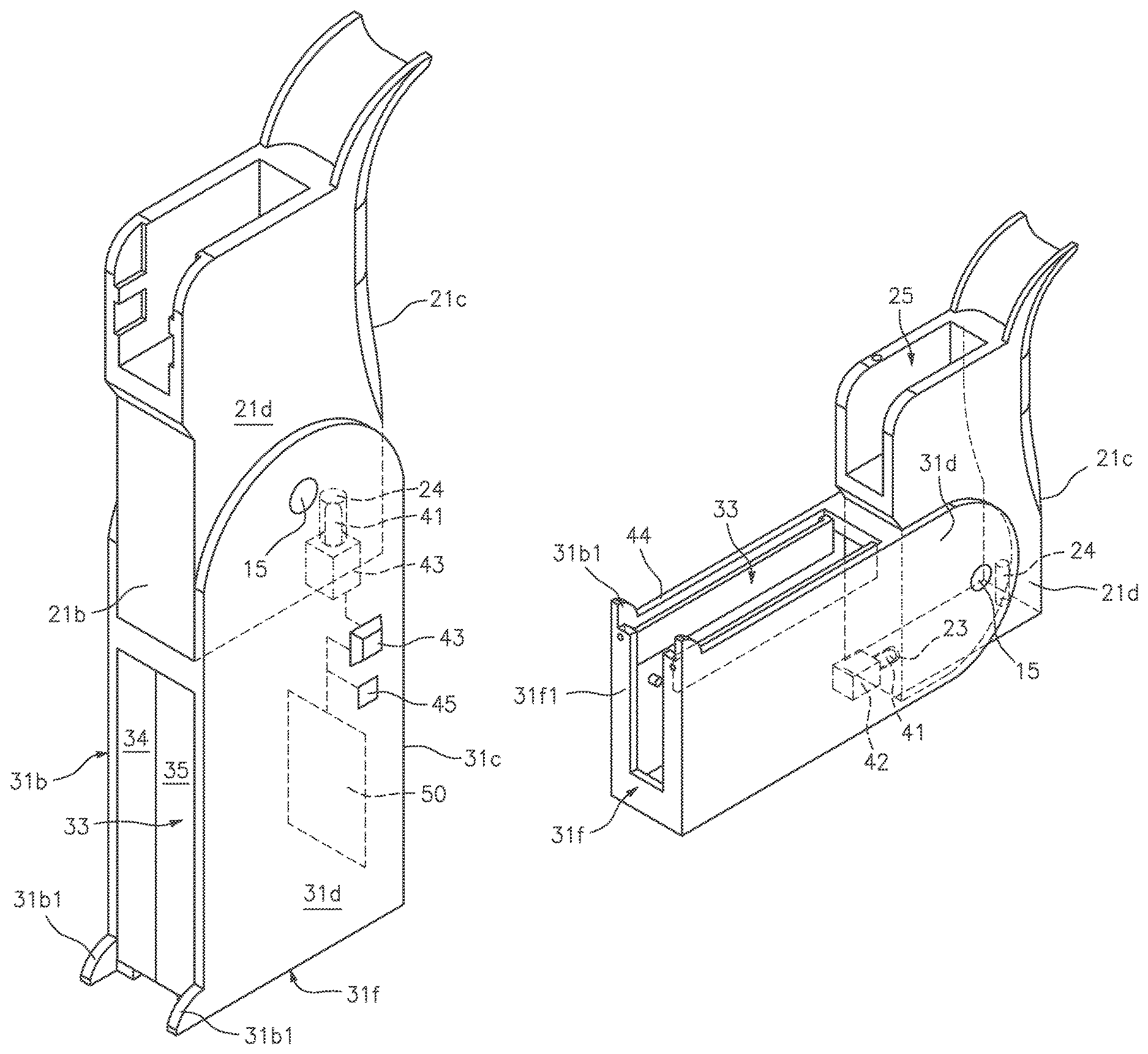
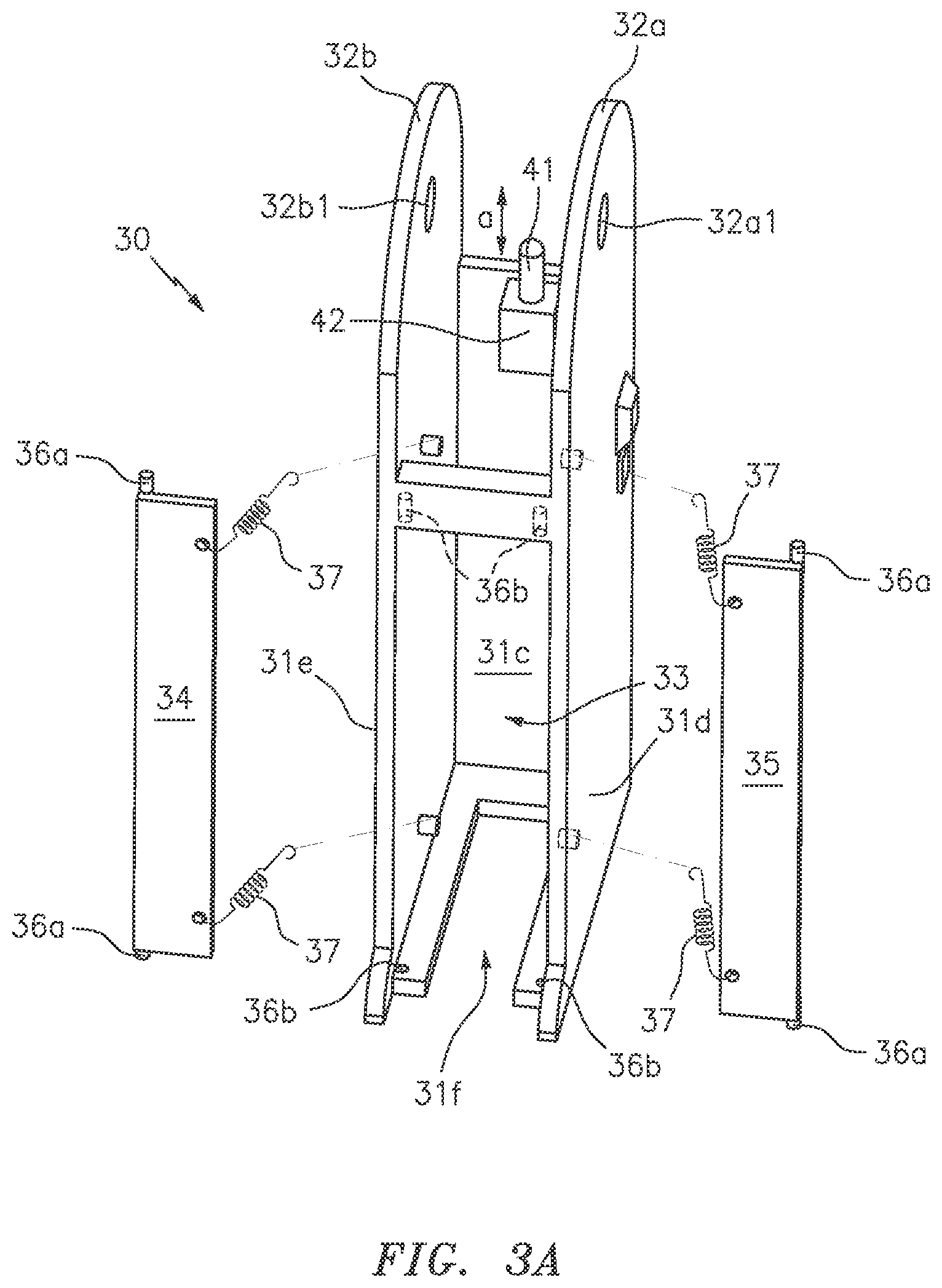
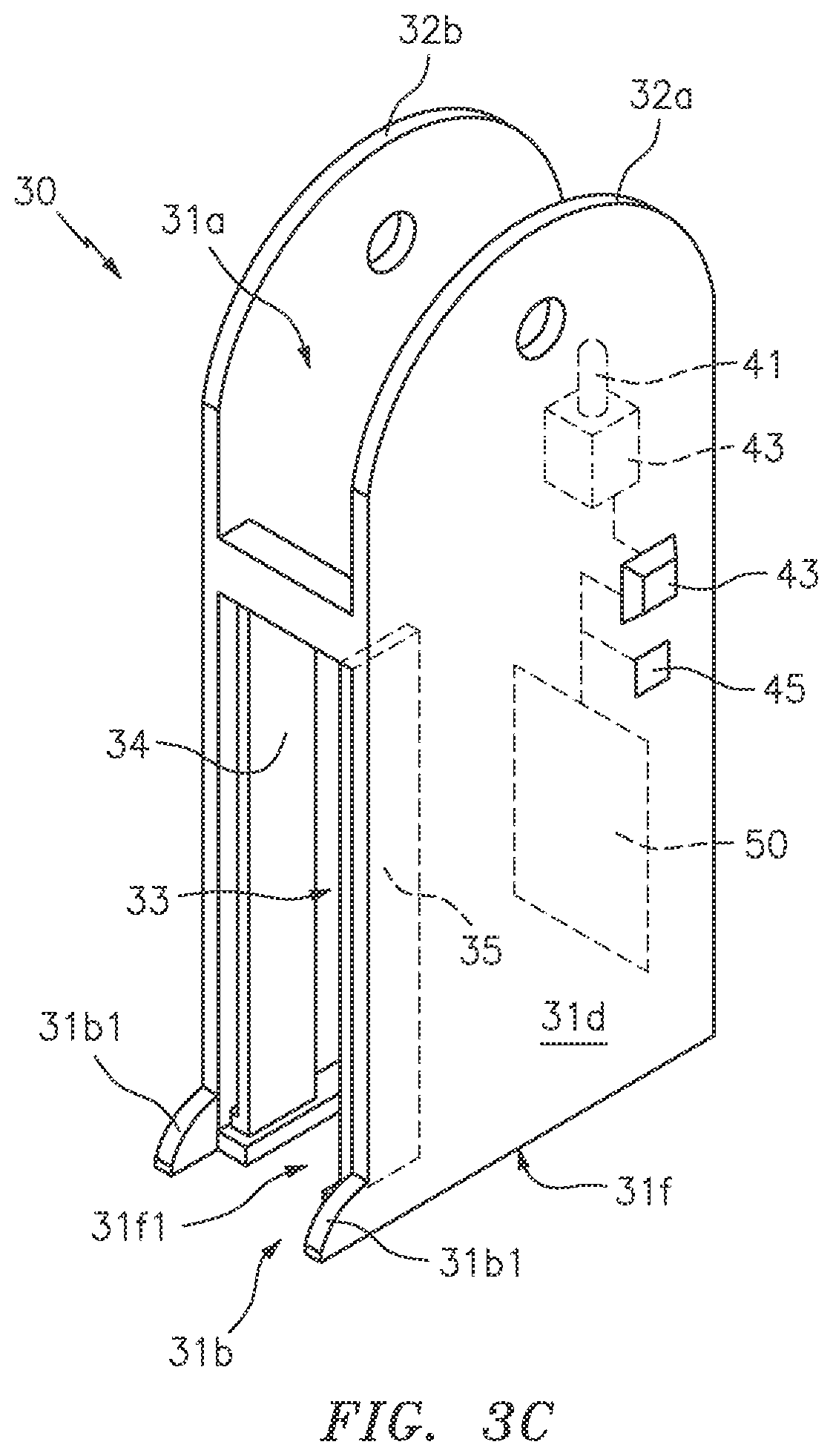
FIGS. 3A-3C illustrate one embodiment of the handgrip 30. As shown, the grip can include an elongated body section having an open top end 31a, a front end 31b, a back end 31c, side walls 31d-31e and a bottom end 31f that define a hollow interior space. In the preferred embodiment, a generally U-shaped channel 31f1 can extend inward along the bottom of the handgrip body, and the front end can include protrusions 31b1 extending away from the front of the handgrip body. The exterior facing portions of the handgrip can include any number of gripping elements such as various finger ridges and/or rough texturing, to aid in a user's ability to grip the device and facilitate ease of use.
A channel having channel walls 32a and 32b can extend upward from the top end 31a of the body section. The bottom end of the engagement member 21f is smaller than the open top end of the grip 31a and is smaller than the dimension of the channel so as to be positioned between the channel walls and/or within the open top end 31a. When so positioned, the large diameter openings 32a1 and 32b1 of the channel are aligned with the openings 22a and 22b to receive the locking pin 15. In this manner, the handgrip 30 can rotate 90 degrees to transition between the FIRE position illustrated in FIG. 6 and the SAFE position illustrated in FIG. 7.
The front end of the of the receiver body 31b can include an elongated opening 33 into which a pair of generally planar doors 34 and 35 are positioned. In one embodiment, each of the doors can include protrusions 36a along one side that extend from the top and bottom ends. These can engage dimples/apertures 36b that are positioned along the edges of the opening 33 so as to allow the doors to pivot between the open position shown at FIG. 3C and the closed position shown at FIG. 3B. Although not specifically illustrated, ridges or other obstructions can be provided along the receiver body to prevent the doors from moving outward and away from the front end of the handgrip body 31b.
When the doors are in the closed position, the doors are positioned perpendicular to the side surfaces of the handgrip and function to completely cover the elongated opening 33. Of course, any number of other ways to secure the doors to the handgrip body are also contemplated. Any number of resilient tensioning members 37 such as springs, for example, can be connected between each door and the interior portion of the handgrip body. The tensioning members functioning to impart a constant pushing force on the doors (e.g., in a direction toward the front end 31b) to maintain the doors in the closed unless acted upon.
As described herein, the handgrip body and each of the doors can be constructed from any number of rigid durable materials such as plastic and/or various metals, for example. Moreover, the handgrip and doors can be constructed to include any number of different shapes and sizes, so as to be compatible with virtually any type of firearm.
Although described above as including a pair of doors, this is for illustrative purposes only. To this end, other embodiments are contemplated wherein a single door is provided that is secured along one side of the grip and functions to selectively open and close in the same manner described above.
A locking mechanism having a retractable rod 41 can be positioned along the inside top portion of the back end 31c of the handgrip body. The rod can be connected to an actuator 42 that extends and retracts the rod linearly as shown by arrow a.
In one embodiment, the actuator 42 can include a mechanical device having any number of tensioning mechanisms such as a spring, for example, that can be manipulated by a push button 43 to allow the rod to extend away from or retract within the top end of the handgrip body 31a. An authentication device 45 can include any number of mechanical or electromechanical devices capable of accepting a user input so as to allow operation of the actuator. When used with a purely mechanical actuator, the authentication device 45 can include a mechanical combination lock having a series of numbers or letters which must be entered in a proper sequence to allow the actuator to move. In this regard, the authentication device can be physically coupled to the actuator 42 or button 43, and can function to block movement of the actuator and rod unless the proper sequence has been entered. Combination locking systems and associated components are extremely well known in the art, and any number of such commercially available systems can be utilized herein.
In one embodiment, the actuator 42 can include or comprise an electromechanical device or assembly such as a linear actuator system, for example. In such an embodiment, the authentication device 45 can preferably include or control a biometric authentication system such as the illustrated fingerprint sensor, for example that is communicatively linked to a system controller 50.
As will be known to those of skill in the art, a biometric authentication system may record the fingerprint of the user and store the image of the fingerprint in the memory 52. As such, upon recognition of the users fingerprint applied to the sensor, the processor can instruct the electromechanical actuator to retract, thereby allowing the grip to transition from the SAFE position to the FIRE position. Of course, the authentication unit is not limited to the use of a biometric sensor, as any number of other known systems for receiving and/or verifying a user input are also contemplated. Several nonlimiting examples include the use of an electromechanical combination lock system and/or a wireless authentication system such as an RFID interrogator that can be used with an externally located RFID sensor, for example.
As shown at FIG. 4A, when the handgrip 30 is positioned perpendicular to the locking mechanism 20, the rod 41 can selectively engage the cylindrical channel 24 that is positioned along the bottom back end 21c of the locking mechanism. When so positioned, and when the device is secured to a firearm 1, this feature secures the handgrip 30 in the FIRE position.
As shown at FIG. 4B, when the handgrip 30 is positioned parallel to the locking mechanism 20, the rod 41 can selectively engage the aperture 23 that is positioned along the front end 21b of the locking mechanism. When so positioned, and when the device is secured to a firearm 1, this feature secures the handgrip 30 in the SAFE position with the trigger assembly locked inside the grip body.
FIG. 5 illustrates one embodiment of an internal control assembly 50 which can function to control an operation of the authentication unit 45 and the actuator 42. In one embodiment, the internal control assembly can include a processor 51 that is conventionally connected to an internal memory 52, a component interface unit 53, and/or a power source 54.
Although illustrated as separate elements, those of skill in the art will recognize that one or more assembly components may comprise or include one or more printed circuit boards (PCB) containing any number of integrated circuit or circuits for completing the activities described herein. The CPU may be one or more integrated circuits having firmware for causing the circuitry to complete the activities described herein. Of course, any number of other analog and/or digital components capable of performing the below described functionality can be provided in place of, or in conjunction with the below described controller elements.
The processor/CPU 51 can act to execute program code stored in the memory 52 in order to allow the device to perform the functionality described herein. Memory 52 can act to store operating instructions in the form of program code for the processor 51 to execute.
The component interface unit 53 can function to provide a communicative link between the processor 51 and various other device components such as the authentication unit 45 and the actuator 42, for example. In this regard, the component interface unit can include any number of different components such as one or more PIC microcontrollers, internal bus, USB connections and other such hardware capable of providing a direct link between the various components. Of course, any other means for providing the two way communication between the device components can also be utilized herein.
In the preferred embodiment, the power source 54 can include one or more DC batteries capable of providing the necessary power requirements to each element of the device 10. In one embodiment, the batteries can be permanently located within the handgrip body 30 and can be rechargeable in nature via a charging port such as a mini or micro USB port, for example. Of course, traditional batteries can also be utilized and the main body can further include a battery compartment having a removable cover (not illustrated) for allowing a user to access the same.
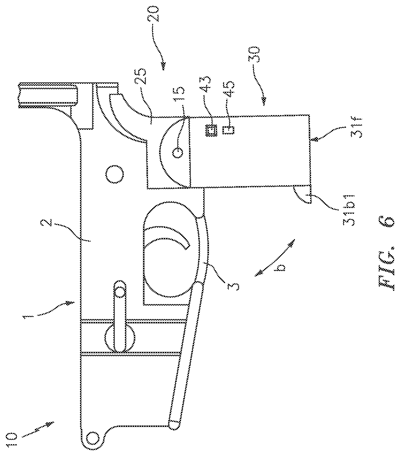
FIG. 6 illustrates one embodiment of the device 10 in operation with a firearm 1 in the FIRE position. As shown the channel portion 25 is mechanically coupled to the firearm receiver 2 adjacent to the trigger assembly 3. In this position, the handgrip body 30 is oriented perpendicular to the major axis of the weapon, and the doors 34-35 are closed so as to provide a continuous gripping surface for a user to hold and fire the weapon.
At this time, the locking mechanism is engaged with the channel on the bottom end of the engagement member 20 to maintain the device 10 in this position for use. When a user wishes to transition the device to the safe position, the user simply engages the button 43 and/or authentication unit 45, and rotates the front of the handgrip body toward the trigger assembly as shown by arrow b.
FIG. 7 illustrates one embodiment of the device 10 in the SAFE position. As shown the channel portion 25 remains mechanically coupled to the firearm receiver 2 adjacent to the trigger assembly 3. As the handgrip body 30 pivots (arrow b) to this position, the bottom end of the trigger assembly engages the doors 34-35 thus overcoming the tensioning mechanisms to move the doors to the open position. With the doors open, the entire trigger assembly, or a majority of the trigger assembly is positioned within the interior space of the handgrip body 30.
At this time, the locking mechanism will engage the aperture on the front of the engagement member 20 to secure the device 10 in the SAFE position where the trigger assembly is inaccessible. Additionally, in this position, the protrusions 31b1 are engaged with the magazine selector switch 4 of the receiver, and the side of the body 31b is engaged with the fire selector switch 5, thus further locking the weapon in the SAFE position. When an authorized user wishes to transition the device to the FIRE position, the user will preferably be required to use the authentication unit 45 to verify their authorization, before the system will allow the button 43 or actuator to move the rod and allow rotation of the handgrip body to the FIRE position.
Although described above with regard to a particular locking mechanism that engages particular components of the engagement member, this is for illustrative purposes only. To this end, any number of other devices capable of selectively locking the device 10 in either the FIRE or SAFE positions are also contemplated. Additionally, other embodiments are contemplated wherein the orientation of the locking mechanism and the aperture/channel of the engagement unit are positioned differently that described above. For example, the locking mechanism can also be secured along the front of the handgrip body, the sides of the handgrip body and/or multiple different locking mechanisms can be positioned along any portion of the handgrip body with the apertures/channels located at corresponding locations along the firearm engagement unit. To this end, other components such as the button 43, authentication device 45, controller 50 and the like can be positioned anywhere along the device components and are not limited to the locations illustrated.
Additionally, as shown in FIG. 8, the device 10 can also include another pair of large bore apertures 80 which can be positioned through the sides of the receiver body. The aperture 80 being positioned so as to receive an external lock 8 which can extend through the trigger assembly 3 in order to provide double redundancy to prevent access to the weapon. This feature being particularly beneficial for use when traveling or shipping a firearm, or for long term storage, for example.
Accordingly, the above described firearm grip with integrated locking mechanism provides an innovative safety solution that can be permanently mounted onto a firearm in order to secure the same in a locked state.
As described herein, one or more elements of the device 10 can be secured together utilizing any number of known attachment means such as, for example, screws, glue, compression fittings and welds, among others. Moreover, although the above embodiments have been described as including separate individual elements, the inventive concepts disclosed herein are not so limiting. To this end, one of skill in the art will recognize that one or more individually identified elements may be formed together as one or more continuous elements, either through manufacturing processes, such as welding, casting, or molding, or through the use of a singular piece of material milled or machined with the aforementioned components forming identifiable sections thereof.
As to a further description of the manner and use of the present invention, the same should be apparent from the above description. Accordingly, no further discussion relating to the manner of usage and operation will be provided.
The terminology used herein is for the purpose of describing particular embodiments only and is not intended to be limiting of the invention. As used herein, the singular forms "a," "an," and "the" are intended to include the plural forms as well, unless the context clearly indicates otherwise. It will be further understood that the terms "comprises" and/or "comprising," when used in this specification, specify the presence of stated features, integers, steps, operations, elements, and/or components, but do not preclude the presence or addition of one or more other features, integers, steps, operations, elements, components, and/or groups thereof. Likewise, the terms "consisting" shall be used to describe only those components identified. In each instance where a device comprises certain elements, it will inherently consist of each of those identified elements as well.
The corresponding structures, materials, acts, and equivalents of all means or step plus function elements in the claims below are intended to include any structure, material, or act for performing the function in combination with other claimed elements as specifically claimed. The description of the present invention has been presented for purposes of illustration and description but is not intended to be exhaustive or limited to the invention in the form disclosed. Many modifications and variations will be apparent to those of ordinary skill in the art without departing from the scope and spirit of the invention. The embodiment was chosen and described in order to best explain the principles of the invention and the practical application, and to enable others of ordinary skill in the art to understand the invention for various embodiments with various modifications as are suited to the particular use contemplated.
* * * * *
D00000
D00001
D00002
D00003
D00004
D00005
D00006
D00007
D00008
D00009
D00010
D00011
XML
uspto.report is an independent third-party trademark research tool that is not affiliated, endorsed, or sponsored by the United States Patent and Trademark Office (USPTO) or any other governmental organization. The information provided by uspto.report is based on publicly available data at the time of writing and is intended for informational purposes only.
While we strive to provide accurate and up-to-date information, we do not guarantee the accuracy, completeness, reliability, or suitability of the information displayed on this site. The use of this site is at your own risk. Any reliance you place on such information is therefore strictly at your own risk.
All official trademark data, including owner information, should be verified by visiting the official USPTO website at www.uspto.gov. This site is not intended to replace professional legal advice and should not be used as a substitute for consulting with a legal professional who is knowledgeable about trademark law.