Cable harness
Shimizu , et al.
U.S. patent number 10,576,915 [Application Number 16/180,442] was granted by the patent office on 2020-03-03 for cable harness. This patent grant is currently assigned to Sumitomo Wiring Systems, Ltd.. The grantee listed for this patent is Sumitomo Wiring Systems, Ltd.. Invention is credited to Toshinari Kobayashi, Gen Nishino, Moriyuki Shimizu.

| United States Patent | 10,576,915 |
| Shimizu , et al. | March 3, 2020 |
Cable harness
Abstract
A cable harness that has water-sealing properties includes a sheath that accommodates a signal line and a power-source line. The signal line may be an ABS sensor cable and the power-source line may be a parking brake cable. The ABS sensor cable and the parking brake cable branch apart at an end portion of the sheath. An integrally molded member includes, in an integrated manner, a water-sealing portion that seals the end portion of the sheath from water, and a bracket attachment portion that is attached to the bracket.
| Inventors: | Shimizu; Moriyuki (Mie, JP), Nishino; Gen (Mie, JP), Kobayashi; Toshinari (Mie, JP) | ||||||||||
|---|---|---|---|---|---|---|---|---|---|---|---|
| Applicant: |
|
||||||||||
| Assignee: | Sumitomo Wiring Systems, Ltd.
(Yokkaichi, Mie, JP) |
||||||||||
| Family ID: | 55857347 | ||||||||||
| Appl. No.: | 16/180,442 | ||||||||||
| Filed: | November 5, 2018 |
Prior Publication Data
| Document Identifier | Publication Date | |
|---|---|---|
| US 20190071036 A1 | Mar 7, 2019 | |
Related U.S. Patent Documents
| Application Number | Filing Date | Patent Number | Issue Date | ||
|---|---|---|---|---|---|
| 15521547 | 10399515 | ||||
| PCT/JP2015/079799 | Oct 22, 2015 | ||||
Foreign Application Priority Data
| Oct 31, 2014 [JP] | 2014-223663 | |||
| Current U.S. Class: | 1/1 |
| Current CPC Class: | H02G 3/0462 (20130101); B60R 16/0215 (20130101); H01B 7/282 (20130101); B60R 16/023 (20130101); H02G 3/0406 (20130101); H01B 7/18 (20130101); H01B 7/0045 (20130101); Y02A 30/14 (20180101); B60T 7/085 (20130101); B60T 7/10 (20130101) |
| Current International Class: | B60R 16/023 (20060101); H01B 7/282 (20060101); H01B 7/18 (20060101); B60T 7/10 (20060101); H01B 7/00 (20060101); B60R 16/02 (20060101); H02G 3/04 (20060101); B60T 7/08 (20060101) |
| Field of Search: | ;174/70C,72A |
References Cited [Referenced By]
U.S. Patent Documents
| 2933550 | April 1960 | Cole |
| 5168124 | December 1992 | Takase et al. |
| 5347089 | September 1994 | Barrat |
| 6069319 | May 2000 | Davis, Jr. |
| 8829350 | September 2014 | Iwasaki et al. |
| 9842671 | December 2017 | Komori |
| 2007/0267212 | November 2007 | Nachbauer |
| 2008/0105454 | May 2008 | Morioka et al. |
| 2011/0088926 | April 2011 | Grogl |
| 2012/0292101 | November 2012 | Kato |
| 2013/0277087 | October 2013 | Hayakawa |
| 2015/0279514 | October 2015 | Sato |
| 2015/0355213 | December 2015 | Kobayashi et al. |
| 2016/0339854 | November 2016 | Hayakawa et al. |
| 2017/0229213 | August 2017 | Sakaki |
| 51-146383 | May 1975 | JP | |||
| 6-267336 | Sep 1994 | JP | |||
| H09-084246 | Mar 1997 | JP | |||
| H10-233124 | Sep 1998 | JP | |||
| 2002-25651 | Jan 2002 | JP | |||
| 3296750 | Jul 2002 | JP | |||
| 2003-151368 | May 2003 | JP | |||
| 2004014475 | Jan 2004 | JP | |||
| 2004014475 | Jan 2004 | JP | |||
| 4794988 | Oct 2011 | JP | |||
| 2012130185 | Jul 2012 | JP | |||
| 2013237428 | Nov 2013 | JP | |||
| 2014-167929 | Sep 2014 | JP | |||
| 2007117653 | Feb 2009 | KR | |||
| 2014103499 | Jul 2014 | WO | |||
Other References
|
Search Report for International Application No. PCT/JP2015/079799, dated Nov. 25, 2015, 4 pgs. cited by applicant. |
Primary Examiner: Thompson; Timothy J
Assistant Examiner: McAllister; Michael F
Attorney, Agent or Firm: Honigman LLP
Parent Case Text
CROSS-REFERENCE TO RELATED APPLICATIONS
This application is a divisional of U.S. patent application Ser. No. 15/521,547 filed on Apr. 24, 2017 which is the U.S. national stage of PCT/JP2015/079799 filed Oct. 22, 2015, which claims priority of Japanese Patent Application No. JP 2014-223663 filed Oct. 31, 2014.
Claims
What is claimed:
1. A cable harness in which at least a signal line and a power-source line are contained inside of a sheath, wherein at an end portion of the sheath, the signal line and the power-line are branched in different directions; and a water-sealing portion disposed on the end portion of the sheath for sealing, from water, the end portion of the sheath and the signal line and the power-source line that are branched from the end portion of the sheath, the end portion of the sheath, the signal line, and the power-source line being embedded in the water sealing portion, and at an end portion of the water-sealing portion at which the signal line and the power source line are drawn out, the signal line and the power-source line are covered by the water sealing portion.
2. The cable harness according to claim 1, wherein a bracket attachment portion for attaching a bracket is integrally provided on the water-sealing portion.
3. The cable harness according to claim 2, wherein the bracket attachment portion is provided on the sheath.
4. The cable harness according to claim 2, wherein the water-sealing portion and the bracket attachment portion are integrally formed of urethane.
5. The cable harness according to claim 1, wherein an electrical line separate from the signal line and the power-source line is further contained inside of the sheath.
6. The cable harness according to claim 5, wherein the electrical line includes two electrical lines for active suspension.
7. The cable harness according to claim 1, wherein the different directions are directions in which the signal line and the power-source line intersect each other.
Description
TECHNICAL FIELD
The present invention relates to a cable harness.
BACKGROUND
Electric parking brake (EPB) mechanisms and antilock brake systems (ABS) are mounted in vehicles such as automobiles.
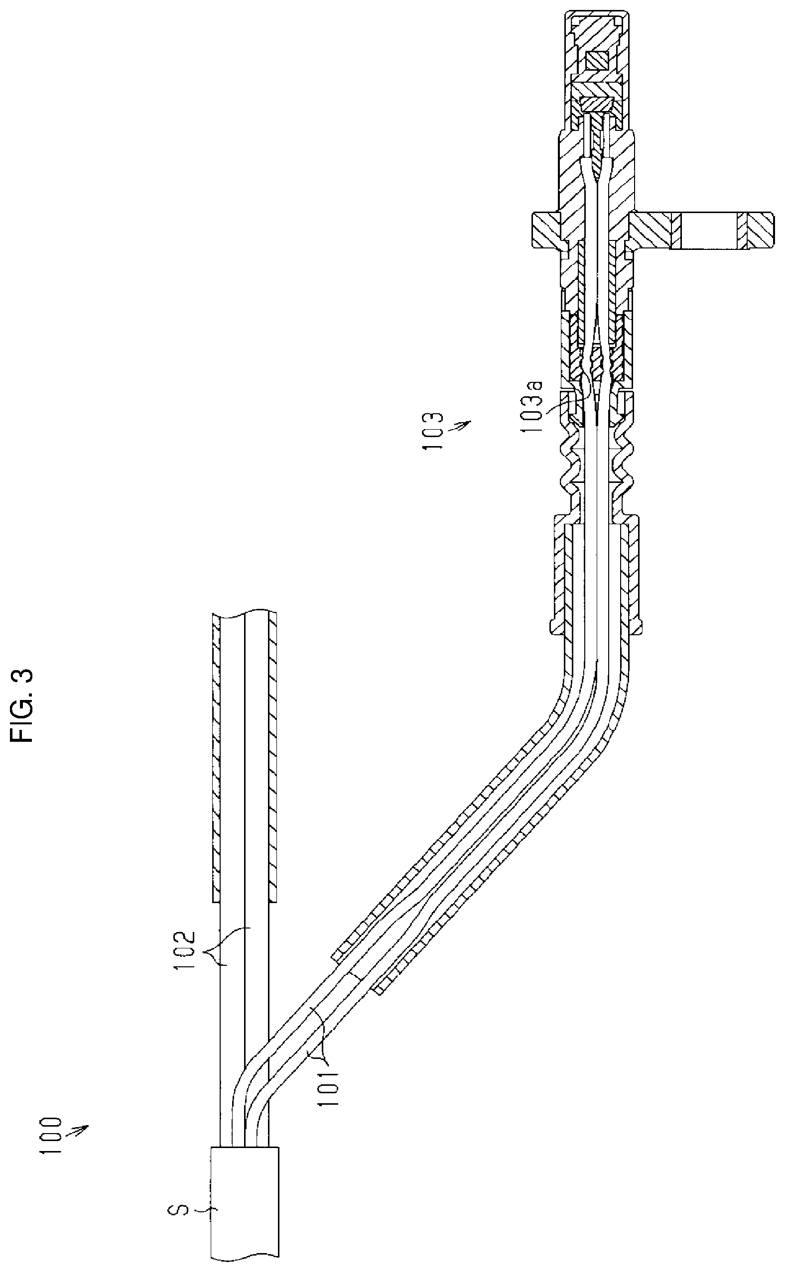
A cable harness 100, as shown in FIG. 3, that includes a single sheath S that covers an EPB system cable 102 and an ABS sensor cable 101 has been developed because the ABS sensor and the EPB mechanism are attached at positions that are close to each other. There are cases where various cables are connected in various types of systems including that described above (e.g. see JP 2013-237428A).
The cables 101 and 102 are to be connected to an ABS sensor 103 and the EPB mechanism respectively, and thus the cables 101 and 102 need to be branched at a mid-point in the cable harness 100. At this time, the sheath S of the cable harness 100 is partially stripped, and thus the cables 101 and 102 are exposed. At this time, there is a concern of water infiltrating into the sheath S. Note that, in FIG. 3, press fitting the cable 101 to a sensor head portion of the ABS sensor 103 provides a water-sealing portion 103a that acts as a water-sealing structure that seals the ABS sensor 103 from water.
There are cases where a bracket for fixedly connecting a cable harness to a mount portion in a vehicle or the like is used.
SUMMARY OF THE INVENTION
The object of the present invention is to provide a cable harness with which the infiltration of water into the sheath can be suppressed while an increase in the number of parts can be suppressed.
An aspect of the present invention is a cable harness that is provided with a sheath that accommodates at least an ABS sensor electrical line and a parking brake electrical line, the cable harness includes: an integrally molded member that includes a water-sealing portion that seals an end portion of the sheath where the ABS sensor electrical line and the parking brake electrical line branch apart, from water; and a bracket attachment portion to which a bracket is attached.
With this configuration, because the end portion of the sheath is sealed from water by the water-sealing portion, and the water-sealing portion and the bracket attachment portion are molded in one piece, an increase in the number of parts can be suppressed. Other facets and advantages of the present invention will be made clear from the drawings showing examples of technical concepts of the present invention and that disclosed below.
BRIEF DESCRIPTION OF DRAWINGS
FIG. 1 is a schematic view of a cable harness according to an embodiment.
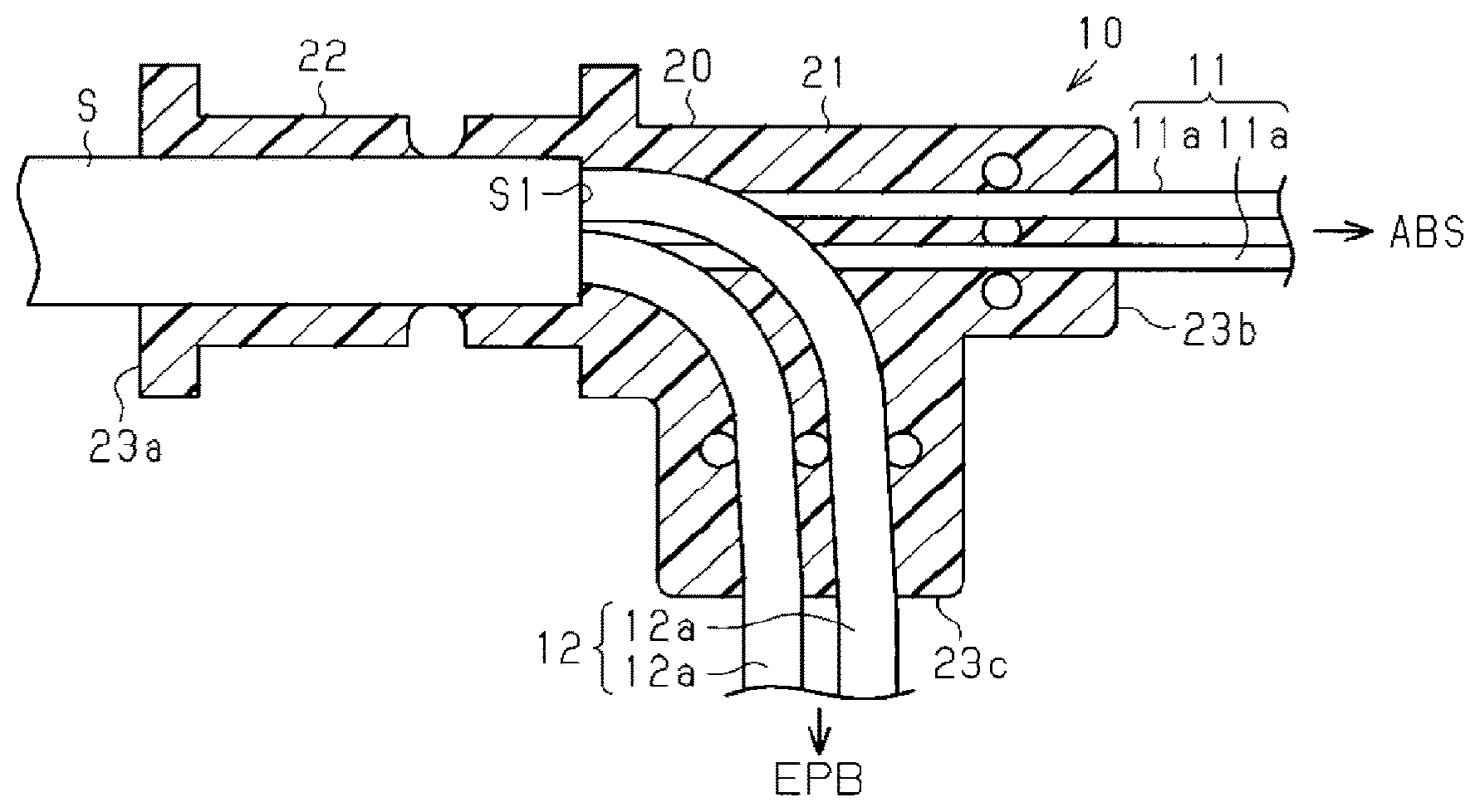
FIG. 2 is a partial cross-sectional diagram for illustrating a water-sealing structure of the cable harness shown in FIG. 1.
FIG. 3 is a cross-sectional diagram of a cable harness according to a reference example.
DETAILED DESCRIPTION OF THE PREFERRED EMBODIMENTS
An embodiment of a cable harness will be described below.
As shown in FIG. 1, a cable harness 10 of the present embodiment is formed by an ABS sensor cable 11 and a parking brake cable 12 being jointly covered by a sheath S and integrated with each other.
As shown in FIG. 2, the ABS sensor cable 11 and the parking brake cable 12 branch apart at an end portion S1 of the sheath S.
As shown in FIG. 1 and FIG. 2, the ABS sensor cable 11 is formed by two signal lines 11a. Each of the signal lines 11a are conductors sheathed in an insulating body. The ABS sensor cable 11 is attached to an ABS sensor at an end thereof.
The parking brake cable 12 is used as an electrical conduction path through which a current flows, which mainly results from a pressing operation being performed on a predetermined button after a vehicle has been parked, the current causing a mechanism (electronic parking brake (EPB)) that is for suppressing rotation of vehicle wheels, to function. The parking brake cable 12 is for electrically connecting an EPB control unit (omitted from the drawings) and an EPB mechanism. For this reason, the parking brake cable 12 has two power-source lines 12a. Also, examples of the EPB mechanism include types where wires in a conventional parking brake mechanism are pulled by an actuator, and types where a dedicated electronic actuator is mounted to a hydraulic brake caliper.
As described above, the sheath S of the cable harness 10 of the present embodiment is configured by a so-called four-core electrical line, with the two signal lines 11a constituting the ABS sensor cable 11 and the two power-source lines 12a constituting the parking brake cable 12 being accommodated therein.
Also, the cable harness 10 of the present embodiment is provided with a molded portion 20, which is a urethane resin member, at the end portion S1 of the sheath S. The molded portion 20 is a member in which a water-sealing portion 21 and a bracket attachment portion 22 are molded in one piece using urethane molding.
The water-sealing portion 21 is formed to cover the region where the end portion S1 of the sheath S, the ABS sensor cable 11, and the parking brake cable 12 branch apart. The ABS sensor cable 11 is drawn out along the longitudinal direction of the sheath S, and the parking brake cable 12 is drawn out so as to be orthogonal to the longitudinal direction of the sheath S and is covered by the water-sealing portion 21.
The bracket attachment portion 22 is molded in one piece with the water-sealing portion 21, on a base end side relative to the end portion S1 of the sheath S, i.e. on a side opposite the region where the ABS sensor cable 11 and the parking brake cable 12 branch apart. The bracket attachment portion 22 has an approximately columnar shape, and a bracket B is crimped and fixed to the bracket attachment portion 22. Note that the bracket B can have a through-hole B1 for attachment. The bracket B and the cable harness 10 can be fixed to a vehicle by using the through-hole B1 and a fastening member such as a bolt.
Next, effects of the present embodiment will be described.
Signals detected by the ABS sensor are transmitted through the cable harness 10 of the present embodiment using the signal lines 11a of the ABS sensor cable 11. Furthermore, power is supplied to the EPB mechanism by the power-source lines 12a of the parking brake cable 12.
Here, the cable harness 10 can suppress the infiltration of water into the sheath S via the end portion S1 thereof because the water-sealing portion 21 covers the region where the end portion S1 of the sheath S, the ABS sensor cable 11, and the parking brake cable 12 branch apart. Also, because the water-sealing portion 21 is formed in one piece with the bracket attachment portion 22 for attaching the bracket B to an unshown vehicle, an increase in the number of parts is suppressed.
Next, the effects of the present embodiment will be described.
Because the water-sealing portion 21 and the bracket attachment portion 22 are molded in one piece and the water-sealing portion 21 also seals the end portion S1 of the sheath S from water, an increase in the number of parts can be prevented.
Compared with the case where a configuration is employed in which the bracket attachment portion and the water-sealing portion are separate members, there is no particular need to provide a gap between the bracket attachment portion 22 and the water sealing portion 21 as they are molded in one piece, and therefore the size of the sheath S of the molded portion 20 can be suppressed in the longitudinal direction thereof.
The directions in which the cables 11 and 12 are drawn out can be fixed by the molded water-sealing portion 21. For example, the molded portion 20 can include a first terminal 23a that is terminated on the sheath S, a second terminal 23b that is terminated on the ABS sensor cable 11, and a third terminal 23c that is terminated on the parking brake cable 12. The second terminal 23b and the third terminal 23c can have different angles with respect to the longitudinal axis of the sheath S (e.g. 0.degree. and 90.degree.).
The molded portion 20 may be a part that is made of a synthetic resin and has no joints. With this configuration, the water-sealing properties of the molded portion 20 can be improved.
The end portion S1 of the sheath S, a portion of the ABS sensor cable 11, and a portion of the parking brake cable 12 are embedded in the molded portion 20. With this configuration, the water-sealing properties of the molded portion 20 can be improved.
It is preferable that the bracket attachment portion 22 covers the sheath S. With such a configuration, stress on the cables 11 and 12 exposed from the sheath S can be mitigated.
It is preferable that the bracket attachment portion 22 includes at least one positioning stopper 22a. With this configuration, positional shifting of the bracket B can be mitigated.
Note that changes such as the following may be made to the above-described embodiment.
In the above-described embodiment, a configuration is employed where the bracket B is crimped and fixed to the bracket attachment portion 22, but there is no limit to this.
In the above-described embodiment, the cable harness 10 is configured by a so-called four-core electrical line, but there is no limit to this. For example, a configuration may be employed using a six-core electrical line that has six electrical lines (cables) in the sheath S of the cable harness 10. An example of a six-core electrical line includes an electrical line where two active suspension electrical lines are passed through the sheath S of the cable harness 10 in addition to the above-described four-core electrical line.
In the above-described embodiment, it is preferable that the material of the molded portion 20 that has the water-sealing portion 21 and the bracket attachment portion 22 is urethane resin, but a synthetic resin other than urethane resin can be used.
The above-described embodiment and variations thereof may be appropriately combined.
The present invention is not limited to that illustrated. For example, illustrated features are not to be interpreted as being essential to the present invention, and the subject matter of the present invention may exist with fewer features than all of those of the specified embodiment thus disclosed.
* * * * *
D00000
D00001
D00002
XML
uspto.report is an independent third-party trademark research tool that is not affiliated, endorsed, or sponsored by the United States Patent and Trademark Office (USPTO) or any other governmental organization. The information provided by uspto.report is based on publicly available data at the time of writing and is intended for informational purposes only.
While we strive to provide accurate and up-to-date information, we do not guarantee the accuracy, completeness, reliability, or suitability of the information displayed on this site. The use of this site is at your own risk. Any reliance you place on such information is therefore strictly at your own risk.
All official trademark data, including owner information, should be verified by visiting the official USPTO website at www.uspto.gov. This site is not intended to replace professional legal advice and should not be used as a substitute for consulting with a legal professional who is knowledgeable about trademark law.